Embed Size (px)
Citation preview
2
PRESENTATION OF MANUAL
INSTRUCTIONS FOR USE
CAUTION
Technical Name: Radiographic Image DigitalizerTrade Name: Intraoral Digital Radiographic SystemModel: New IDABrand: EAGLE
Manufacturer/ Distribuitor:Dabi Atlante S/A Indústrias Médico Odontológica Avenida Presidente Castelo Branco, 2525 - CEP 14095-000 Ribeirão Preto - S.P. - Brasil Phone: 55 (16) 3512-1212 CNPJ: 55.979.736.0001/45
Technical Duties: Caetano Barros Biagi CREA-SP: 5061859382
Registration ANVISA #: 10101139025
For improved safety:
Read and understand all the instructions contained in the Instructions for Use before installation or operation of this equipment.
The Instructions for Use must be read by all persons that operate this equipment.
The Instructions for Use were originally written in Portuguese. However, they are also supplied in English and Spanish.
3
INDEX02 PRESENTATION OF MANUAL
04 IDENTIFICATION OF EQUIPMENT04 Indication of Equipment 04 Use04 Declaration
04 INTRODUCTION
05 SYMBOLS
06 CAUTION, PRECAUTIONS AND RECOMMENDATIONS06 Caution and/or precautions during transport and storage 06 Environmental conditions for transport and storage06 Conditions for installation and equipment operation06 Ambient packing away conditions07 Procedure prior to use of the equipment07 During equipment installation07 Precautions and/or caution during equipment use08 After use / equipment operation08 Precautions in the event of a change in the equipment operation
09 SPECIFICATIONS AND TECHNICAL FEATURES09 General Information11 Electromagnetic Emmissions
15 PARTS AND ACCESSORIES
16 SYSTEM REQUIREMENTS
17 INSTALLATION
21 MAIN SCREEN
22 INTERFACE ICONS
27 SETTINGS
28 USE OF THE SENSOR
32 CALIBRATION PROCESS
33 ODONTOGRAM
35 CLEANING AND MAINTENANCE
35 DIAGNOSTIC ERRORS
36 DABI ATLANTE AUTHORISED SERVICE NETWORK
36 PRECAUTIONS IN THE EVENT OF EQUIPMENT DISPOSAL
36 WARRANTY

4
IDENTIFICATION OF EQUIPMENTDear CustomerCongratulations. You have made a good choice when you decided to buy a EAGLE QUALITY product comparable to the best products available in the World. This manual is a general presentation of your product and it will give you important details to help you to solve possible problems.Please, read it and keep this with you.
Indication of EquipmentThis equipment is for dental use use only. It must be operated and utilized by specialized professional (certified professional, according to the legislation of the country) and following the instructions of the manual. The operation of the equipment required, for the professional, the utilization of correct instruments and it should to be in perfect conditions of the use, and to protect the professional, the patients and others, in the eventual danger situation.
IDENTIFICATION
UseThe New IDA Digital Radiographic System is intended for intra-oral radiographic dental examinations for the diagnosis of diseases of the teeth, jaw and oral structures. Such examinations must be carried out by an accredited dental professional in the environment of a dental surgery.
Technical Name: Radiographic Image DigitalizerTrade Name: Intraoral Digital Radiographic SystemModel: New IDABrand: EAGLE
DeclarationOnly personnel authorized by Dabi Atlante are qualified for the maintenance of this equipment. Any attempt to maintain this equipment by unauthorized personnel will void the product warranty.It is essential that this equipment is installed and operated by personnel familiar with the necessary precautions to avoid excessive exposure to both primary and secondary radiation. This equipment does provide protection to limit both primary and secondary radiation produced by X-ray beams. However, such design characteristics should not preclude the adoption of preventative measures to further avoid exposure to such radiation.
The New IDA Digital Radiographic System employs a sensor that uses CMOS (Complementary Metal--Oxide-Semiconductor) associated technology, protective fibre optics and scintillation. This sensor was developed to obtain high quality digital X-ray images of the dental arcade and its structures. The capture process is carried out by positioning the sensor inside the mouth behind the structure that is to be examined. The structure must be exposed to an external X-ray source. Once exposed the sensor converts X-ray photons into a digital signal and transfers it to a computer via a USB (Universal Serial Bus) connection.Dental image management software then interfaces between the New IDA system and the user, making it possible to view, enhance, store, send, and print an image, among other functions.
INTRODUCTION
5
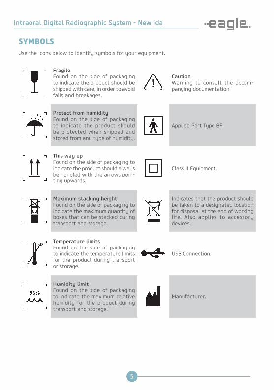
Use the icons below to identify symbols for your equipment.
FragileFound on the side of packaging to indicate the product should be shipped with care, in order to avoid falls and breakages.
CautionWarning to consult the accom-panying documentation.
Protect from humidityFound on the side of packaging to indicate the product should be protected when shipped and stored from any type of humidity.
Applied Part Type BF.
This way upFound on the side of packaging to indicate the product should always be handled with the arrows poin-ting upwards.
Class II Equipment.
Maximum stacking heightFound on the side of packaging to indicate the maximum quantity of boxes that can be stacked during transport and storage.
Indicates that the product should be taken to a designated location for disposal at the end of working life. Also applies to accessory devices.
Temperature limitsFound on the side of packaging to indicate the temperature limits for the product during transport or storage.
USB Connection.
Humidity limitFound on the side of packaging to indicate the maximum relative humidity for the product during transport and storage.
Manufacturer.
SYMBOLS

6
Caution and/or precautions during transport and storageThe equipment must be transported and stored, as follows:• Care should be taken to avoid impacts and breakages• Packaging arrows should point upward• Do not stack over the quantity indicated on packaging• Protect against humidity, water and dust
Environmental conditions for transport and storage
Ambient temperature range for transport and storage +10ºC to +50ºC
Relative humidity range for transport and storage < 90% RH
Atmospheric pressure range 700 hPa to 1060 hPa(525 mmHg to 795 mmHg)
Conditions for installation and equipment operation
Operating ambient temperature range +15˚C to +30˚C
Operational non-condensing relative humidity range 30% to 75% (no condensing)
Atmospheric pressure range 700 hPa to 1060 hPa (525 mmHg to 795 mmHg)
Ambient packing away conditions (between operations)
Ambient temperature range for packing away +10˚C to +30˚C
Ambient temperature range recommended by Dabi Atlante +21˚C to +26˚C
Non-condensing relative humidity range for packing away 30% to 75% (no condensing)
Atmospheric pressure range 700 hPa to 1060 hPa(525 mmHg to 795 mmHg)
CAUTION, PRECAUTIONS AND RECOMMENDATIONS

7
Procedure prior to use of the equipmentBefore initial use the equipment must be cleaned and disinfected, as described in manual, the same procedures must be followed for maintenance.
During equipment installation• Place the equipment in a location where it will not come into contact with water or humidity.• Install the unit in a location where it will not be damaged by pressure, temperature, humidity, direct sunlight, dust, salts or corrosive products.• The equipment should not be subjected to excessive vibration or shock (including during transport and/or handling).• This equipment is not intended for use in the presence of flammable anesthetic vapor mixtures or nitrous oxide.• The equipment must be properly sited, as stated in the manual, to avoid any risk of falls.• Recommendations stated herein, regarding EMC standards, must be followed. Communications equipment and RF sources may affect the operation of this equipment.• This equipment is for the exclusive use of health professionals.
Precautions and/or caution during equipment use• The equipment must only be operated by properly qualified and trained technicians.• In the event of maintenance, use only services provided by an Authorised Technical Support Service.• Exposure to X-rays may cause cellular damage to the human body. It is recommended that no person remain in the radiographic examination room, unless it is necessary to stay with the patient. In this case, that person must be suitably protected against the emission of radiation.• The equipment was designed in accordance with electromagnetic compatibility standards but under extreme conditions may cause interference with other equipment. Do not use this equipment together with other devices sensitive to interference or with devices that create high levels of electromagnetic disturbance.
CAUTION, PRECAUTIONS AND RECOMMENDATIONS

8
Caution
The manufacturer is not liable for:• Equipment used for purposes other than that for which it was designed.• Damage caused to equipment, the operator and/or patient, as a result of incorrect installation and maintenance procedures at variance with the ope-rating instructions supplied with the equipment.• Improper operation of the equipment.
After use / equipment operation• Unplug the unit when not in use for an extended period.• Always keep the equipment clean and ready for next use.• Do not modify any part of the equipment.• Do not disconnect the cable or other connections unnecessarily.
Precautions in the event of a change in the equipment operationIf the equipment displays any abnormality check whether the problem is related to any item listed under the heading “Diagnostic errors - page 35”.If it is not possible to solve the problem, unplug the equipment, disconnect the cables and seek assistance from Dabi Atlante Authorized Technical Support.
CAUTION, PRECAUTIONS AND RECOMMENDATIONS
9
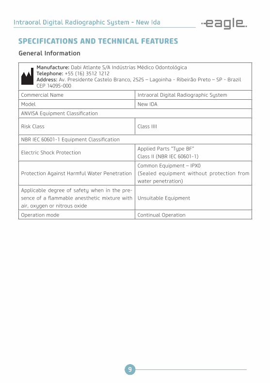
SPECIFICATIONS AND TECHNICAL FEATURES
Manufacture: Dabi Atlante S/A Indústrias Médico Odontológica Telephone: +55 (16) 3512 1212 Address: Av. Presidente Castelo Branco, 2525 – Lagoinha - Ribeirão Preto – SP - Brazil CEP 14095-000
Commercial Name Intraoral Digital Radiographic System
Model New IDA
ANVISA Equipment Classification
Risk Class Class IIII
NBR IEC 60601-1 Equipment Classification
Electric Shock ProtectionApplied Parts “Type BF“ Class II (NBR IEC 60601-1)
Protection Against Harmful Water PenetrationCommon Equipment – IPX0 (Sealed equipment without protection from water penetration)
Applicable degree of safety when in the pre-sence of a flammable anesthetic mixture with air, oxygen or nitrous oxide
Unsuitable Equipment
Operation mode Continual Operation
General Information

10
General Features
Tamanho* 0 1 2
Sensor resolution(lp/mm) 25 25 25
External dimensions (mm) 22,5 x 29,7 27,5 x 37,7 32,5 x 44,7
Active area dimensions (mm) 17 x 22 20 x 30 26 x 36
Matrix dimensions 850 x 1100 1000 x 1500 1300 x 1800
Number of pixels (MegaPixels) 0,93 1,50 2,34
Technology CMOS CMOS CMOS
Gray level 4096 4096 4096
Image resolution 12 bits 12 bits 12 bits
Image format TIFF, JPG, PNG, BMP DICOM
TIFF, JPG, PNG, BMP DICOM
TIFF, JPG, PNG, BMP DICOM
Optical fiber 1 1 1
Weight 60 g 65 g 70 g
Connection USB2 – High Speed USB2 – High Speed USB2 – High Speed
Cable Length 3 meters 3 meters 3 meters
* Purchase on request.
SPECIFICATIONS AND TECHNICAL FEATURES
11
Electromagnetic Emmissions
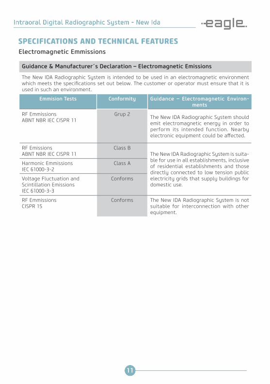
Guidance & Manufacturer´s Declaration – Electromagnetic Emissions
The New IDA Radiographic System is intended to be used in an electromagnetic environment which meets the specifications set out below. The customer or operator must ensure that it is used in such an environment.
Emmision Tests Conformity Guidance – Electromagnetic Environ-ments
RF Emmissions ABNT NBR IEC CISPR 11
Grup 2 The New IDA Radiographic System should emit electromagnetic energy in order to perform its intended function. Nearby electronic equipment could be affected.
RF Emissions ABNT NBR IEC CISPR 11
Class BThe New IDA Radiographic System is suita-ble for use in all establishments, inclusive of residential establishments and those directly connected to low tension public electricity grids that supply buildings for domestic use.
Harmonic Emmissions IEC 61000-3-2
Class A
Voltage Fluctuation and Scintillation Emissions IEC 61000-3-3
Conforms
RF Emmissions CISPR 15
Conforms The New IDA Radiographic System is not suitable for interconnection with other equipment.
SPECIFICATIONS AND TECHNICAL FEATURES

12
Electromagnetic Immunity
Guidance & Manufacturer´s Declaration – Electromagnetic Immunity
The New IDA Radiographic System is intended to be used in an electromagnetic environment which meets the specifications set out below. The customer or operator must ensure that it is used in such an environment.
Immunity Tests ABNT NBR IEC 60601 Test Leve Conformity Level Guidance – Electromagnetic
Environments
Electrostatic Discharge (ESD) IEC 61000-4-2
± 6 kV by contact± 8 kV by air
± 6 kV by contact± 8 kV by air
Floors should be wood, con-crete or ceramic. If floors are covered with a synthetic material, relative humidity should be at least 30%
Electr ica l fast Transient / Burst Immunity IEC 61000-4-4
± 2 kV for power supply lines ± 1 kV for input / output lines
± 2 kV for power supply lines ± 1 kV for input / output lines
Power supply quality should be that of a typical hospital or commercial environment.
Surges IEC 61000-4-5
±1 kV differential mode ± 2 kV common mode
±1 kV differential mode ± 2 kV common mode
Power supply quality should be that of a typical hospital or commercial environment.
Voltage Dips, Short Interruptions and Voltage Variations Immunity Tests (for input power supply lines) IEC 61000-4-11
< 5% Uτ (>95% voltage drop in Uτ) for a 0.5 cycle. 40% Uτ (60% voltage drop in Uτ) for 5 cycles. 70% Uτ (30% voltage drop in Uτ) for 25 cycles. <5% Uτ (>95% voltage drop in Uτ) for 5 seconds.
< 5% Uτ (>95% voltage drop in Uτ) for a 0.5 cycle. 40% Uτ (60% voltage drop in Uτ) for 5 cycles. 70% Uτ (30% voltage drop in Uτ) for 25 cycles. <5% Uτ (>95% voltage drop in Uτ) for 5 seconds.
Power supply quality should be that of a typical hospital or commercial environment. If the New IDA Digital Radio-graphic System user needs to ensure continuous opera-tion in the event of a power failure, it is recommended that the New IDA Digital Radiographic System is po-wered via an uninterrupted power supply or a battery.
Power Frequency Magnetic Field Immun i ty Test (50/60 Hz) IEC 61000-4-8
3 A/m 3 A/m Magnetic fields for power supply frequencies should be at levels characteristic of a typical hospital or com-mercial environment.
NOTE Ut is the AC power supply voltage prior to application of the test standard.
SPECIFICATIONS AND TECHNICAL FEATURES
13
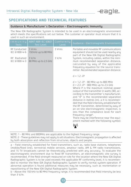
Guidance & Manufacturer´s Declaration – Electromagnetic Immunity
The New IDA Radiographic System is intended to be used in an electromagnetic environment which meets the specifications set out below. The customer or operator must ensure that it is used in such an environment.
I m m u n i t y Tests
ABNT NBR IEC 60601 Test Level
Comformity Level Guidance – Electromagnetic Environments
RF Conducted IEC 61000-4-6
RF Radiated IEC 61000-4-3
3 Vrms150 kHz up to 80 MHz
3 V/m80 MHz up to 2,5 GHz
3 Vrms
3 V/m
Portable and movable RF communications equipment should not be used nearby any part of the New IDA Digital Radiographic System, including cables, within the mini-mum recommended separation distance, calculated by way of the applicable frequency equation for the source trans-mitter. Recommended separation distance:
d = 1.2 √P
d = 1,2 √P - 80 MHz up to 800 MHzd = 2,3 √P - 800 MHz up to 2,5 GHzWhere P is the maximum nominal power output of the transmitter in watts (W), ac-cording to the transmitter´s manufacturer, and "d" is the recommended separation distance in metres (m). a It is recommen-ded that the field intensity established for the RF transmitter, determined by way of an on-site electromagnetic inspection, is less than the compliance level for each frequency rangeb. There may be interference near the equi-pment marked with the following symbol:
NOTE: 1 - 80 MHz and 800MHz are applicable to the highest frequency range. NOTE: 2 - These guidelines may not apply to all situations. Electromagnetic propagation is affected by both absorption and reflection from structures, objects and people.
a - Field intensity established for fixed transmitters, such as, radio base stations, telephones (mobile/fixed line), terrestrial mobile services, amateur radio, AM & FM radio transmissions, and 15 TV broadcasts cannot be theoretically predicted with any accuracy. To evaluate the electromagnetic environment due to fixed RF transmitters, an electromagnetic site survey is recommended. If the field strength measured on-site for the location where the New IDA Digital Radiographic System is to be used exceeds the applicable RF conformity level, it is recommen-ded to monitor the New IDA Digital Radiographic System to verify normal system operation. If abnormal operation is found additional measures may be necessary, such as reorientation or repositioning of the New IDA Digital Radiographic System.b - Above the 150 kHz to 80 MHz frequency range, it is recommended that field intensity be less than 3 V/m.
SPECIFICATIONS AND TECHNICAL FEATURES

14
Recommended separation distances between portable and fixed RF communication equipment and the New IDA Digital Radiographic SystemThe New IDA Digital Radiographic System is designed for use in an electromagnetic environment in which RF signals are controlled. The customer or user can help prevent electromagnetic interfe-rence by way of maintaining a minimum distance between portable and fixed RF communications equipment (transmitters) and the New IDA Digital Radiographic System, as recommended below, in accordance with the maximum output power of such communication equipment.
Nominal Maximum Power Output for
Transmitter (W)
Separation distance according to transmitter frequency (m)
150 kHz up to 80 MHzd= 1,2√p
80 MHz up to 800 MHzd= 1,2√p
800 MHz up to 2,5 GHzd= 2,3√p
0,01 0,12 0,12 0,23
0,1 0,38 0,38 0,73
1 1,2 1,2 2,3
10 3,8 3,8 7,3
100 12 12 23
For transmitters that have a nominal maximum power output not listed above, the minimum recommended separation distance "d" in metres (m) can be determined by use of the equation applied to the transmitter´s frequency, where P is nominal maximum power output for the trans-mitter in watts (W), according to the transmitter´s manufacturer.
NOTE: 1 - 80 MHz and 800MHz are applicable to the separation distance for the highest frequency range. NOTE: 2 - These guidelines may not apply to all situations. Electromagnetic propagation is affected by both absorption and reflection from structures, objects and people.
Caution
This equipment should not be used alongside or supported by other equipment. Recommendations set out in this manual should be followed.
Caution
To prevent accidents during use the user must move away from the equipment for safety reasons, in order to avoid collision with moving parts. The patient should be informed about all movements that equipment will make and should also be asked not to move during the process. The user is obliged to continually watch the patient and interrupt the operation in the event that the patient moves. Important: the force of the equipment´s movement, even if it comes to collide with the patient, is not sufficient to cause any damage, even when used with children.
Caution
Do not use accessories, transducers, internal component parts and cables, other than those previously specified by the manufacturer. Such use could result in an increase in emissions or a decrease in electromagnetic immunity.
SPECIFICATIONS AND TECHNICAL FEATURES

15
PARTS AND ACCESSORIESMain part of the sensor
Intraoral Radiographic Sensor
The sensor allow the capture of intraoral radiographic images.
* Purchase on request
Caution
The serial number of the sensor is located on the label affixed to the back of the electronic device.
Caution
The setup contained on the installation flash drive features all sensor calibra-tion files, so it can not be used with another sensor.
Installation flash driver
Pendrive contento o software de manipulação de imagem, drives e manuais.
Product warranty
Case

16
SYSTEM REQUIREMENTSComputer operating systemThe computer operating system should meet the following requirements:
Caution
It is recommended to periodically back up patient information.
Operating System Windows 7 (x86 e x64) - Home, Starter, ProWindows 8 (x86 e x64) - ProWindows 8.1 (x86 e x64) - ProWindows 10 (x86 e x64) - Home, Pro
CPU Intel i5 3.0 Ghz or superior
HDD 500 GB
RAM 2GB DDR2 SDRAM
Monitor 1024x768
USB Connector 2 x USB 2.0 – 500mA
Power requirementsThe New IDA sensor does not require its own external power supply, as its power is supplied via the computer´s USB connection. It has an approximate power consumption of 300mA.
Caution
IMPORTANTDo not use USB ports available on keyboards or on the front and/or side of the computer. These connections are often incapable of supplying sufficient power for proper functioning of the sensor.
Periapical radiography equipmentThe sensor is compatible with any periapical X-ray equipment with an electronic timer, as long as it complies with current regulations. The X-ray generator should work at a voltage of between 60 and 70kV.
Caution
Do not use source generators of less than 60KVof power.

17
LocalCheck there is sufficient space to position the computer system and the sensor.Position the computer and monitor within the operating area in such a way as to ensure adequate ventilation.Use monitors with features that are compatible with X-ray clichés (preferably 4:3). Position the screen so as to avoid any direct light or reflections that could hinder the display of images.Position the sensor, electronic module and accessories near to the patient, at a distance of about 1.5 meters. Only the sensor and the electronic module can be placed close to the patient. It should not be possible for the patient to touch the computer or its peripherals.
INSTALLATIONConnect the Pendrive that came with the New IDA in USB port, open the device and click the file Setup.exe
Select the desired language and click OK
Read and understand the License Agreement to End User and if acceptable, click I accept the agreement. Click Next.
SYSTEM REQUIREMENTS

18
INSTALLATIONSelect the dialog box if you want to create an icon on the desktop and click Next.
Click Install to start the installation process.
Setup will install .NET 4.5.1

19
Click "I Agree"
Click "Install"
Wait for the installation to finish and click "Close"
INSTALLATION

20
Setup will install the USB driver. Press Install to start the installation process.
Press Finish to complete the installation.
INSTALLATION
21
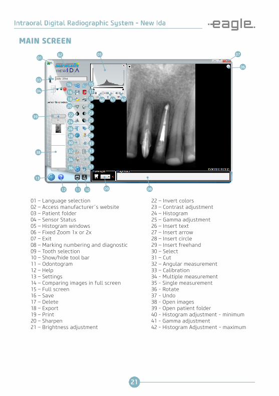
MAIN SCREEN
01 – Language selection02 – Access manufacturer´s website03 – Patient folder04 – Sensor Status05 – Histogram windows06 – Fixed Zoom 1x or 2x07 – Exit08 – Marking numbering and diagnostic09 – Tooth selection10 – Show/hide tool bar11 – Odontogram12 – Help13 – Settings14 – Comparing images in full screen15 – Full screen16 – Save17 – Delete18 – Export19 – Print20 – Sharpen21 – Brightness adjustment
22 – Invert colors23 – Contrast adjustment24 – Histogram25 – Gamma adjustment26 – Insert text27 – Insert arrow28 – Insert circle29 – Insert freehand30 – Select31 – Cut32 – Angular measurement33 – Calibration34 - Multiple measurement35 - Single measurement36 - Rotate37 - Undo38 - Open images39 - Open patient folder40 - Histogram adjustment - minimum41 - Gamma adjustment42 - Histogram Adjustment - maximum
0102
03
0414
20
22
24
26
28
30
32
34 35
33
31
29
27
25
23
21
19
17
15
06
3736
13
12 11 10 09 08
05
16
18
38
07
39
40 41 42

22
INTERFACE ICONS
Icons Functions
ExitTo exit the application
MaximizeTo maximize the application
MinimizeTo minimize the application
SettingsAllows access to your computers parameters (format and file pathways for database images, download locations)
Create a new folder for the patientEnables you to create a new folder (new patient)
Access patient recordAllows access to the saved database for patients
Open patient recordAllows access to the history for the folder displayed in the interface and to open previously saved files
Scroll upAllows library images displayed to be scrolled through ver-tically
Scroll down Allows library images displayed to be scrolled through ver-tically
Zoom x1To magnify the image 1x
Zoom x2 To magnify the image 2x
Image rotationAllows the image to be rotated through 90°
23
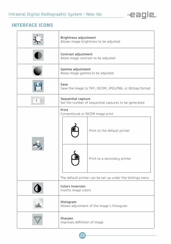
Brightness adjustmentAllows image brightness to be adjusted
Contrast adjustment Allow image contrast to be adjusted
Gamma adjustmentAllow image gamma to be adjusted
Save Save the image to TIFF, DICOM, JPEG,PNG, or Bitmap format
Sequential capture Set the number of sequential captures to be generated
PrintConventional or DICOM image print
Print to the default printer
Print to a secondary printer
The default printer can be set up under the Settings menu
Colors InversionInverts image colors
HistogramAllows adjustment of the image´s histogram
SharpenImproves definition of image
INTERFACE ICONS
24
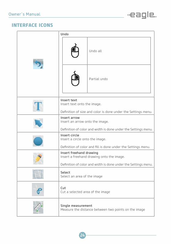
Undo
Undo all
Partial undo
Insert text Insert text onto the image.
Definition of size and color is done under the Settings menu.
Insert arrow Insert an arrow onto the image.
Definition of color and width is done under the Settings menu.
Insert circle Insert a circle onto the image.
Definition of color and fill is done under the Settings menu.
Insert freehand drawing Insert a freehand drawing onto the image.
Definition of color and width is done under the Settings menu.
Select Select an area of the image
Cut Cut a selected area of the image
Single measurement Measure the distance between two points on the image
INTERFACE ICONS

25
Multiple measurement Measures the distance between multiple points on the image
Angular measurementPerforms angular measurements on the image
CalibrationCalibrates a distance on the image
Full ScreenChange the visualization mode for full screen
Full screenComparing images in full screen
Show/hide tool barShow/hide tool bar with features of marking/associating the image
OdontogramAccess the odontogram mode
Histogram windowsAutomatically opens when loading or capturing an image(configurable in the options menu)
Tooth selection boxUsed to mark the tooth (teeth) that appears in the image. It hasa “delete” button to undo the marking
Undo AllUndo All when clicking with the right button on the undo button. The option is only available to the images that were already changed and saved
INTERFACE ICONS

26
Delete ImagePermanently deletes the image on display
ExportIt allows to save an image copy with another name in severalstandard image formats
SharpenThe same feature used in the pre- processing is available in 4 levels of intensity to be applied by the user.Only available for TIFF images without markings. It is recom-mended to use it right after capturing an image.
INTERFACE ICONS
27
SETTINGS
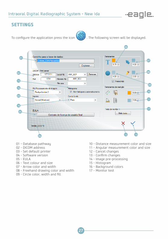
01 - Database pathway02 - DICOM address03 - Set default printer04 - Software version05 - EULA06 - Text colour and size07 - Arrow color and width08 - Freehand drawing color and width09 - Circle color, width and fill
10 - Distance measurement color and size11 - Angular measurement color and size12 - Cancel changes13 - Confirm changes14 - Image pre-processing 15 - Histogram16 - Background colors17 - Monitor test
To configure the application press the icon . The following screen will be displayed.
05
07
13
06
08
09
10
11
12
03
14
15
1617
01
02
04

28
USE OF THE SENSORTo use the New IDA Digital Radiographic System, start up the computer and ensure the System is connected.
Start the application• Start the software by clicking on the desktop shortcut icon or via Start → All Programs → New IDA.• The initial application screen will appear.
Opening an existing folder• Click on the Patient icon.• Select the directory for the patient that you wish to open.• Click on OK to confirm or click on Cancel to go back to the initial interface.

29
Create a new folder• Click on the Paciente + icon. • Next, click on the Create new patient icon.• Type the name for the folder you wish to create. Next, click OK.
Sensor status
• Select the newly created folder and click OK.• The folder name appears in the capture window. Images will be stored in this folder.
Symbol Color Sensor status
Blue iconThe sensor is in standby mode. The sensor is connected and recognized by the application. Click on Start to activate the sensor.
Green icon The sensor is active and ready to receive X-rays.
Red icon Sensor is not connected, capture cancelled or sensor error.
USE OF THE SENSOR

30
Image capture process
• Select the exposure time required with a periapical X-ray timer.• Place the sensor in a protective plastic cover and check that is also covers the part of the cable in contact with the patient´s mouth.
Caution
The sensor must be used with a plastic protector to avoid cross contamination.
Caution
The protective shield must be changed for each patient to avoid any risk of cross contamination.
Caution
Follow the cleaning and sterilization procedure for positioners and for the sensor, on each change of patient, to avoid cross contamination.
• If used, place the sensor in a positioner.
• Place the sensor in the mouth.• The active surface of the sensor must be positioned toward the direction of the X-ray source (opposite cable outlet).
• The sensor can be placed by hand or with the use of a positioner.
Active Surface
Caution
We recommend the use of a positioner in order to obtain the correct angle.
USE OF THE SENSOR

31
• Locate the source generator in the same way as for conventional film.• On the applications interface, click on START CAPTURE.
• The sensor icon changes to green. The sensor is active and waiting for X-rays.• The sensor remains active for 120 seconds. A progress bar indicates the countdown time.
• At the end of this time, if no X-rays have been emitted, the sensor will return to standby. Simply click START CAPTURE again to reactivate.
• The sensor can be deactivated at any time, by clicking on Cancel.• Check the sensor is active (green) before initiating a capture. Active Surface.• Perform the exposure with the X-ray generator to capture an image.• After exposure, the image will appear on the application’s display screen.
Caution
• Always keep the sensor in its box when not in use.• Avoid touching the monitor and the sensor at the same time. This will prevent electrostatic generation and discharge that may cause permanent damage to the equipment.
USE OF THE SENSOR

32
CALIBRATION PROCESS
• Carry out an image capture which contains an object the size of which is known.
• After this step click on the Calibration icon .• Trace a line between the two points the distance of which is known.• The system will display the distance in pixels and in millimeters.
Caution
The calibration process must only be carried out once, so the system adapts to the method used by the professional.
• Type in the distance in millimeters and click Accept.

33
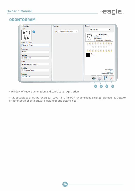
ODONTOGRAM
Help button (23). It opens a window with an illustrated guide to help on the Odontogram tools usage.
23
Help Odontogram
It allows organize the images according to the tooth, to set image history for each tooth and gene-rate treatment report. It is possible to view the images history or start the capture of a new image by clicking with the right button of the mouse on the desired tooth.
34
- Window of report generation and clinic data registration.
- It is possible to print the record (a), save it in a file.PDF (c), send it by email (b) (it requires Outlookor other email client software installed) and Delete it (d).
dcba
ODONTOGRAM

35
CLEANING AND MAINTENANCE
Atenção
DO NOT:- Submerge the electronic module in liquid disinfectant.- Sterilize the sensor or the electronic module using an autoclave or sterilizer.- Pull on the sensor cable.- Allow the sensor to fall.- Request the patient to bite on the cable or sensor.- Switch off the sensor when it is active (120 seconds).
* ANVISA / MINISTRY OF HEALTH NOTIFIED PRODUCT, PROCESS No.: 25351.199946/2009-45, IS NOT SUPPLIED ALONG WITH THIS PRODUCT.
Daily cleaning
• After use on each patient the protective plastic should be removed and the New IDA sensor ca-refully disinfected, including the first 30 cm of cable.• The sensor and electronic module can be cleaned using a soft, clean cloth dampened with Aplic Odonto* or another product with disinfectant properties.• Follow the manufacturer´s safety precautions when using disinfectants.
Symptoms Diagnosis and Solutions
The sensor interface icon is not displayed.
The sensor is not recognised by the computer or is switched off.- Check that the USB cable is correctly connected to the computer and to the electronic module.- Disconnect and reconnect the sensor to the computer again.
No image appears after the emission of X-rays.
- Check the sensor has been activated ("START" icon), before triggering X-rays (green). - Check the generator source is functioning correctly.- Check that the surface of the sensor is correctly orientated toward the X-ray source and that it is correctly aligned.
Very light image.
- Exposure time insufficient.- Source generator voltage insufficient (<60kV). Check source generator.- Check monitor settings (brightness and contrast).
Very dark image. - Exposure time too long.
Completely blank image. - The active face of the sensor was not exposed to X-rays.- Insufficient X-ray dose.
DIAGNOSTIC ERRORSIn the event of problems operating the sensor, check the following:
In the event of any outstanding issues, contact Dabi Atlante Authorized Technical Support.

36
DABI ATLANTE AUTHORISED SERVICE NETWORKInstallation and all services carried out on Dabi Atlante equipment must be performed by Authorized Technical Support otherwise the equipment will not be covered under the warranty.In the event that electrical wiring diagrams are needed and/or specifications for components that are not set out in the User Manual, enter into contact with the Dabi Atlante Customer Service Centre to make a request.
Telephone: (16) 3512-1212E-mail: [email protected]: Av. Presidente Castelo Branco, 2525 – Lagoinha - Ribeirão Preto-SP/ Brazil - CEP 14095-000
PRECAUTIONS IN THE EVENT OF EQUIPMENT DISPOSALEnvironmental contamination
To avoid environmental contamination or misuse of the New IDA where it is meant for disposal, such should be discarded (in compliance with current legislation) in an appropriate location, as extant internal materials may contaminate the environment.The device contains some parts that, at the end of the working life of the unit, should be disposed of in an appropriate location to comply with current legislation.
Dabi Atlante is not responsible for disposal undertaken by the user or for the cost of any res-pective interventions.
WARRANTYThe warranty certificate, in three copies, should be completed by Dabi Atlante Authorised Tech-nical Support, where one copy will be supplied along with delivery to the owner as proof of the equipment´s warranty. The two remaining copies will be supplied one to the Distributer and the other to the manufacturer.The warranty is limited to the repair or replacement of defective parts by the manufacturer, not including the repair of defects arising from:- Non-compliance with the operating or maintenance instructions- Falls or breakages- Improper storage- Action of nature agents;- Installation and technical assistant from personnel not authorised by Dabi Atlante- Damage to either painted or unpainted parts as a result of improper use
Warranty period:The manufacturer supplies a 12 (twelve) month warranty from the date of installation, against defective parts, raw-materials and hardware manufacturing defects. In the event that defects occur within the warranty period, spare parts and labour will be provided for the replacement of items covered by the warranty.
THE MANUFACTURER IS NOT RESPONSIBLE FOR ANY OTHER WARRANTY, EITHER EXPRESS OR IMPLIED, INCLUSIVE, BUT NOT LIMITED TO, IMPLIED WARRANTY OF MERCHANTABILITY OR FITNESS FOR PURPOSE AND THOSE THAT MAY ARISE OUT OF A TRANSACTION OR FROM COMMERCIAL USE.
The warranty expressly does not apply to the following items: disposable parts, defects or damage caused by negligence, misuse, operator error, improper installation, modifications or operations not

37
specified for the hardware product by the manufacturer.
WHERE THE AFOREMENTIOEND CONDITIONS HAVE OCCURRED THE MANUFACTURER WILL NOT BE RES-PONSIBLE FOR ANY DAMAGE, WHETHER DIRECT, INDIRECT, SEVERE OR NEGLIGABLE THAT MAY OCCUR, REGARDLESS OF ANY LEGAL ARGUMENT PROPOSED, INCLUSIVE OF STRICT LIABILITY AND NEGLIGENCE.
In no event will the manufacturer will be held liable in any of the following circumstances:- Performance or failure of any network used by the Customer.- Performance or failure of any third party equipment or software.- Impacts on networks or equipment by third parties.- Virus caused by third parties.
WARRANTY

38
39

![[PPT]PowerPoint Presentation - دانشگاه علوم پزشکی بوشهرdnt.bpums.ac.ir/UploadedFiles/CourseFiles/bone1__27a80f... · Web viewTransient osteopetrosis Radiographic](https://img.pdfslide.net/doc/110x75/5aab48e97f8b9a2e088ba039/pptpowerpoint-presentation-dntbpumsaciruploadedfilescoursefilesbone127a80fweb.jpg)