Embed Size (px)
Citation preview

Copyright © 2015-2018. All rights reserved.This publication is produced by SUREBRIDGE work group. Any duplication or use of objects such as diagrams in other electronic or printedpublications is not permitted without the author's agreement.
This project has received funding from the European Union’s Seventh Framework Programme for research, technological development anddemonstration under grant agreement No. 31109806.0009SUREBRIDGE is co-funded by Funding Partners of The ERA-NET Plus Infravation and the European Commission. The Funding Partners of theInfravation 2014 Call are:MINISTERIE VAN INFRASTRUCTUUR EN MILIEU, RIJKSWATERSTAATBUNDESMINISTERIUM FÜR VERKEHR, BAU UND STADTENTWICKLUNG,DANISH ROAD DIRECTORATE,STATENS VEGVESEN VEGDIREKTORATET,TRAFIKVERKET – TRV,VEGAGERÐIN,MINISTERE DE L'ECOLOGIE, DU DEVELOPPEMENT DURABLE ET DE L'ENERGIE,CENTRO PARA EL DESARROLLO TECNOLOGICO INDUSTRIAL,ANAS S.p.A.,NETIVEI, ISRAEL - NATIONAL TRANSPORT INFRASTRUCTURE COMPANY LTD,FEDERAL HIGHWAY ADMINISTRATION USDOT
Presentation title
Workpackage No. AuthorDate

SUREbridgeSustainable refurbishment of existing (concrete) bridges
• Restoring the load carrying capacity of aged and deteriorated bridges
• By combining two technologies: • InfraCore FRP decks on top
for deck restoration and additional compressive capacity
• Prestressed carbon external reinforcement on underside for additional tensile capacity

Finishings to the SUREbridge-system

State of the art
Prototype analysis
Client demands
Connection deck-to-concrete
Fabrication
Partial tests
Deck-design and connections between deck-segments
Full-scale tests
Fabrication
Develop design tool
Operating procedure
2015 2016 2017 2018
WP2
WP3
WP4
progress
Phasing and progress
Pilot projectNext step:

Refurbishment completed
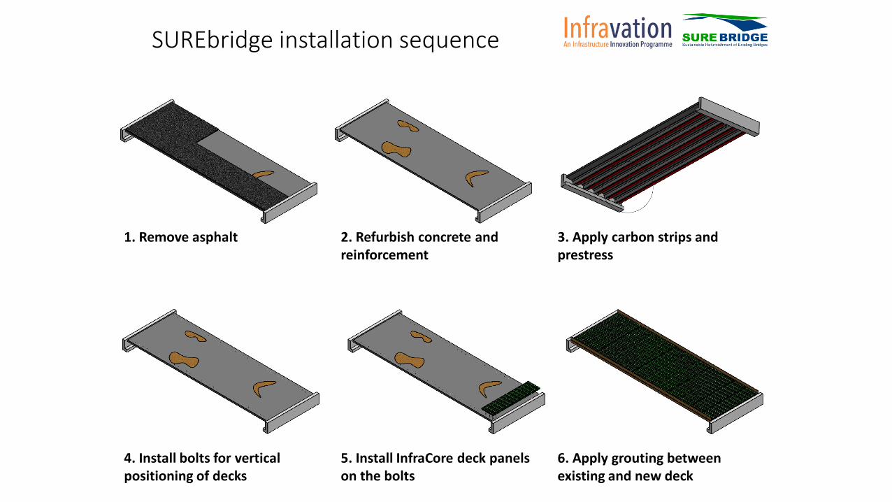
1. Remove asphalt 2. Refurbish concrete and reinforcement
3. Apply carbon strips and prestress
4. Install bolts for vertical positioning of decks
5. Install InfraCore deck panels on the bolts
6. Apply grouting betweenexisting and new deck
SUREbridge installation sequence

Overview of the lab test in CTH Bending test of prototype beams
and GFRP panelsAugust 2018Jincheng Yang
CTHSUREBridge Consortium Meeting
2017-08-29

9
Content
• Four-point bending of prototype beamsReference T-beam
T-beam + prestressed CFRP + Trans. GFRP panel (Mortar bonding)
T-beam + prestressed CFRP + Longt. GFRP panel (Mortar bonding)
T-beam + prestressed CFRP + Longt. GFRP panel (Epoxy bonding)
• Test setup and measurements
• Load-deflection curve
• Videos
• Three-point bending of GFRP panel• GFRP L1 & L2 with webs in longitudinal direction
• GFRP T1 & T2 with webs in transverse direction
• Load-deflection curves
• E-modulus from lab test and comparison
• Failure modes

10
Content
• Four-point bending of prototype beamsReference T-beam
T-beam + prestressed CFRP + Trans. GFRP panel (Mortar bonding)
T-beam + prestressed CFRP + Longt. GFRP panel (Mortar bonding)
T-beam + prestressed CFRP + Longt. GFRP panel (Epoxy bonding)
• Test setup and measurements
• Load-deflection curve
• Videos
• Three-point bending of GFRP panel• GFRP L1 & L2 with webs in longitudinal direction
• GFRP T1 & T2 with webs in transverse direction
• Load-deflection curves
• E-modulus from lab test and comparison
• Failure modes

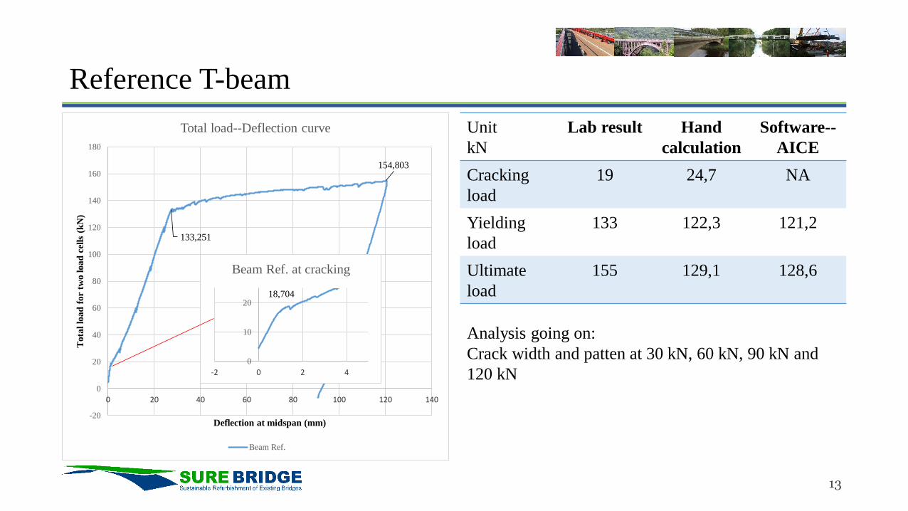
Reference T-beam

12
Reference T-beam
13
Reference T-beam
Unit
kN
Lab result Hand
calculation
Software--
AICE
Cracking
load
19 24,7 NA
Yielding
load
133 122,3 121,2
Ultimate
load
155 129,1 128,6
133,251
154,803
-20
0
20
40
60
80
100
120
140
160
180
0 20 40 60 80 100 120 140
Tota
l lo
ad
for
two load
cel
ls (
kN
)
Deflection at midspan (mm)
Total load--Deflection curve
Beam Ref.
18,704
0
10
20
-2 0 2 4
Beam Ref. at cracking
Analysis going on:
Crack width and patten at 30 kN, 60 kN, 90 kN and
120 kN

T-beam + prestressed CFRP + Trans. GFRP panel (Mortar bonding)

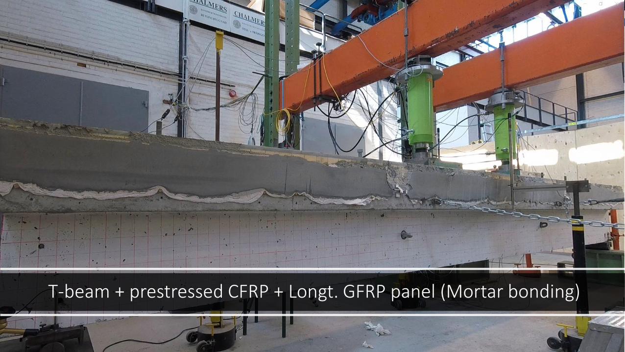
T-beam + prestressed CFRP + Longt. GFRP panel (Mortar bonding)


18
T-beam + prestressed CFRP + Longt. GFRP panel (Mortar bonding)
Unit
kN
Lab result Hand
calculation
Software--
AICE
Cracking
load
~76
Yielding
load
~325
CFRP
rupture
~404
75,525
325,552
403,892
-100
0
100
200
300
400
500
-50 0 50 100 150 200 250
Tota
l lo
ad
for
two load
cel
ls (
kN
)
Deflection at midspan (mm)
Total load--Deflection curve Note: Manually unload and reload
again. Adjust the constrain chain to
allow large deformation
Analysis going on:
• Compare the hand calculation and Software output
with lab result
• Crack width and pattern
Cracking
Yielding
CFRP rupture
Check the link to watch the video of testing
https://drive.google.com/open?id=0B2Qwly0bhIAGc3
IyVnZBTWVyWDQ

19
T-beam + prestressed CFRP + Longt. GFRP panel (Mortar bonding)
Bottom skin of GFRP panel
Mortar layer 30 mm
Flange of T-beam
DIC monitoring:
Using high solution camera to monitor the painted
area by taking pictures every 30 seconds. Digital
correlation software will be used to analyze the
photos and evaluate the field displacement during
the loadign process.

20
T-beam + prestressed CFRP + Longt. GFRP panel (Mortar bonding)
Bottom skin of GFRP panel
Mortar layer 30 mm
Flange of T-beam
Linear profile of
displacement in x-
direction along the black
line in the field.
DIC monitoring showed
full-composite action
between GFRP panel and
concrete beam

T-beam + prestressed CFRP + Longt. GFRP panel (Epoxy bonding)


23
T-beam + prestressed CFRP + Longt. GFRP panel (Epoxy bonding)
Unit
kN
Lab result Hand
calculation
Software--
AICE
Cracking
load
~65
Yielding
load
~307
CFRP
rupture
~397
65,478
306,934
397,189
-50
0
50
100
150
200
250
300
350
400
450
-20 0 20 40 60 80 100 120 140 160 180
Tota
l lo
ad
for
two load
cel
ls (
kN
)
Deflection at midspan (mm)
Total load--Deflection curve
Analysis going on:
• Compare the hand calculation and Software output
with lab result
• Crack width and pattern
Cracking
Yielding
CFRP rupture
Check the link to watch the video of testing
https://drive.google.com/open?id=0B2Qwly0bhIAGQz
NqQ0luMkdHNnc

24
Load-deflection curves of 4 prototype beams
-100
0
100
200
300
400
500
-50 0 50 100 150 200 250
Tota
l lo
ad
from
tw
olo
ad
cell
s k
N
Midspan deflection mm
Load—deflection curves
GFRP
Longt._Mortar bond
GFRP
Longt._Epoxy bond
GFRP
Trans._Mortar bond
Reference beam
-20
0
20
40
60
80
100
-2 0 2 4 6 8 10
Load—deflection curves

Three-point bending of GFRP panels

26
Three-point bending of GFRP panels
-120
-100
-80
-60
-40
-20
0
0 10 20 30 40 50 60 70
To
tal fo
rce
(kN
)
Midspan deflection (mm)
GFRP panel with transverse webs
T2 T1-500
-450
-400
-350
-300
-250
-200
-150
-100
-50
0
0 20 40 60 80 100
To
tal fo
rce
(kN
)
Midspan deflection (mm)
GFRP panel with longitudinal webs
L2 L1
Note
1. T1—monotonic loading from 0 till failure at 111.6 kN
2. T2—cyclic loading
• 10 cycles: 0 kN 77 kN0 kN
• Final loading from 0 till failure at 111.6kN (coinsidence,
pefect match)
3. Failure mode—shear failure in the web/skin connection, crack
opening in the core material
4. Good match between T1 curve and the final loading step of T2
Note
1. L1—monotonic loading from 0 till failure at 369.2 kN
2. T2—cyclic loading
• 10 cycles: 0 kN 262 kN0 kN
• Final loading from 0 till failure at 435 kN
3. Failure mode
• L1—top skin buckling and delamination
• L2—failure in bottom skin due to delaminate
4. Good match between L1 curve and the final loading step of L2

27
Three-point bending of GFRP panels
-120
-100
-80
-60
-40
-20
0
0 10 20 30 40 50 60 70
To
tal fo
rce
(kN
)
Midspan deflection (mm)
GFRP panel with transverse webs
T2 T1-500
-450
-400
-350
-300
-250
-200
-150
-100
-50
0
0 20 40 60 80 100
To
tal fo
rce
(kN
)
Midspan deflection (mm)
GFRP panel with longitudinal webs
L2 L1
Specimen No Loading *Lab test E-
modulus
GPa
Lab test E-modulus in
Avergage
GPa
E-modulus in Datasheet
from FCE
GPa
(E.lab-E.fce)/E.lab
GFRP panel with transverse web T1 Monotonic loading 15,04 15,02 17 (E.22) -13,1%
T2 Cyclic loading 15,00
GFRP panel with longitudinal web L1 Monotonic loading 26,89 27,00 32 (E.11) -18,5%
L2 Cyclic loading 27,12
*Lab test E-modulus—the E-modulus in the span direction calculated from the test result of load and midspan deflection curve

28
Three-point bending of GFRP panels
-150
-100
-50
0
0 10 20 30 40 50 60 70
To
tal fo
rce
(kN
)
Midspan deflection (mm)
GFRP panel with transverse webs
T2 T1
T1
T2
T1Failure model of T1 and T2

29
Three-point bending of GFRP panels
-500
-400
-300
-200
-100
0
0 20 40 60 80 100
To
tal fo
rce
(kN
)
Midspan deflection (mm)
GFRP panel with longitudinal webs
L2 L1
L1
L1
Failure model of L1 and L2
L1
L2-East side
L2-west side
L2-west side

30
GFRP panels--Video and photos
Please use the link below to watch the video and photos of the panel tests:
https://drive.google.com/drive/folders/0B2Qwly0bhIAGb05pUnJMTGszb0E?usp=sharing

Thank you for your attention!


![GFRP [Hand lay up]](https://img.pdfslide.net/doc/110x75/557cb1dcd8b42abf328b4c0e/gfrp-hand-lay-up.jpg)