Embed Size (px)
Citation preview

Presented by: David Beamish
DeFelsko Corporation
Update to SSPC-PA 9Paint Application Specification
Measurement of Dry Coating Thickness Using Ultrasonic Gages
September 2015

“The New PA 9”Content
Background of SSPC-PA 9 Overview and Scope of SSPC-PA 9 (2015) Purpose of ASTM D6132-13 Gage Descriptions Calibration & Verification of Accuracy Measurement Procedures Frequency and Number of Measurements Conformance to Specified Thickness Content of the two Appendices

Overview The document focuses on the correct method for taking
measurements
Includes criteria for determining:– Number and location of measurements– Whether or not the DFT conforms to project specifications
Applies to ultrasonic devices specifically designed to measure coating thicknesses
Procedures described in SSPC-PA 9 are intended to supplement manufacturers’ operating instructions

There is only 1 previous version which was published 2008.
Current version dated July 20, 2015
Background of SSPC-PA 9

SSPC-PA 9 extends the functionality of ASTM D6132
ASTM D6132-13 describes“how” to use the gage
SSPC-PA 9 (2015) focuses on acceptability of acquired measurements by describing “where” and “how often”
Background of SSPC-PA 9
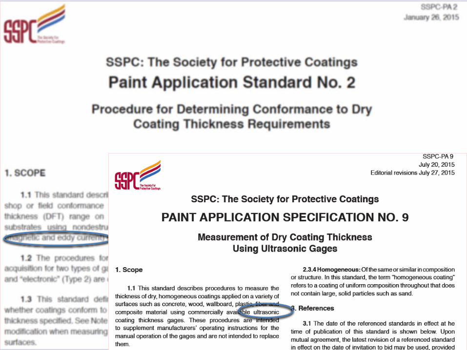
Describes procedures to measure the thickness of dry, homogeneous coatings applied on a variety of surfaces
Homogeneous: Refers to a coating of uniform composition throughout that does not contain large, solid particles such as sand.
Ultrasonic gages are not recommended for coatings such as mortars which are heavily filled with aggregate.
Scope of SSPC-PA 9

Describes procedures to measure the thickness of dry, homogeneous coatings applied on a variety of surfaces
Thickness readings can be verified using destructive means –ASTM D4138
Scope of SSPC-PA 9
Measurements are acquired using purpose-built ultrasonic coating thickness gages
Procedures for gage calibration, verification of accuracy and adjustment are described
Procedure for determining conformance to specified thickness range over extended areas is described
Standard is not intended to prescribe a frequency of measurement for a coating failure investigation
Standard contains two non-mandatory appendices
Scope of SSPC-PA 9

Gage Description Must be capable of measuring coatings
over non-metallic substrates
Gages shall be calibrated and verified according to the manufacturer’s instructions and ASTM D6132
Ultrasonic thickness gages measure polymer coating thicknesses from ~0.3 to 300 mils. The upper limit depends on the acoustical properties of the material being measured and the transducer in the probe.

Gage Description
Ultrasonic vibrations reflect off coating interfaces

Three Steps
1. Calibration and verification of gage accuracy (section 5)
2. Measurement procedures (section 6)
3. Conformance to specified thickness (section 7)

Calibration and Verification Shall be performed in accordance with ASTM D6132
Step 1 of 3

ASTM D6132 ASTM D6132 describes 3 operational steps to ensure
accurate measurement:
1. Calibration
2. Verification of Accuracy
3. Adjustment
These steps must be completed before coating thickness data acquisition.

Gage Calibration “Calibration of coating thickness gages is performed by
the equipment manufacturer, their authorized agent, or by an accredited calibration laboratory in a controlled environment using a documented process.”
Certificate of Calibration traceable to a National Metrology Institute can be issued
No standard time interval for re-calibration, (established based on experience & work environment) but 1-year is typical
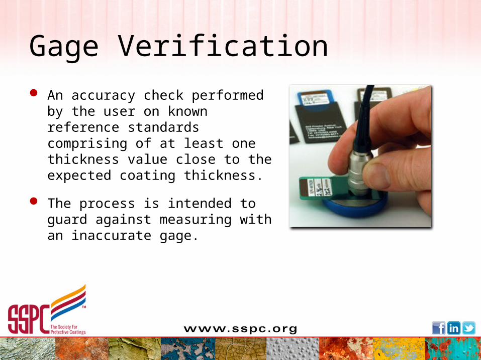
Gage Verification An accuracy check performed by
the user on known reference standards comprising of at least one thickness value close to the expected coating thickness.
The process is intended to guard against measuring with an inaccurate gage.

Gage Verification Shall be performed, at a minimum, at the beginning and
end of each work shift
If the gage is dropped or suspected of giving erroneous readings during the work shift, its accuracy shall be rechecked

Gage Verification Record the:
– Serial number of the gage
– The reference standard used
– The state thickness of the reference standard as well as the measured thickness value obtained
– The method used to verify gage accuracy

Three Steps
1. Calibration and verification of gage accuracy (section 5)
2. Measurement procedures (section 6)
3. Conformance to specified thickness (section 7)

Measurement ProcedureStep 2 of 3
Gage Reading: A single instrument reading.
Spot Measurement: The average of at least 3 gage readings made within a 6” diameter circle.
Any unusually high or low gage readings that are not repeated consistently are discarded.
Area Measurement: The average of 5 separate spot measurements over each 100 ft2 of coated surface.

Area Measurement Average of 5 separate spot measurements over each 100
ft2 of coated surface
1. For areas not exceeding 300 ft2, each 100 ft2 is measured
2. For areas 300 - 1000 ft2 , three 100 ft2 areas are selected and measured
3. For areas greater than 1,000 ft2, the first 1,000 ft2 has three 100 ft2 area measurements selected. For each additional 1000 ft2, one area measurement is selected

Area Measurement for 100 ft2

Measurement Frequency

Size of Coated Area: 900 square feet
No. of Areas: 3No. of Spots: 15 (3 Areas x 5 Spots/Area)
Minimum No. of Gage Readings:45 (15 Spots x 3
Readings/Spot)
Measurement Frequency Example

Size of Coated Area: 55,000 square feet
No. of Areas: 57 (3 + 54)No. of Spots: 285 (57 Areas x 5 Spots/Area)
Minimum No. of Gage Readings:855 (285 Spots x 3
Readings/Spot)
Measurement Frequency Example

Nonconforming Area If the coating thickness for a 100 ft2 area is not in
compliance:
Determine the spot DFT at 5 ft. intervals in 8 equally spaced directions radiating outward from the nonconforming 100 ft2 area up to the limit of area coated during the work shift
Acquire spot measurements in each direction until 2 consecutive conforming spot measurements are acquired in that direction or until no additional measurements are possible

5 ftNO
OK
OK
STOP
OK
OK
STOP
OK
OKSTOP
OKSTOP 5 ft5 ftOK
STOP
OK
OK
Dashed line indicates boundary of area painted during work shift
Suspect area preceding a nonconforming spot must be re-measured after corrections are made
OK
NO
STOP
OK
OK
(Limit of area coated during work shift)
5 ft
5 ft
5 ft
5 ft
5 ft
5 ft
5 ft
STOPOK
5 ft
5 ft
5 ft
5 ft
Dashed line indicates boundary of area painted during work shift
Da
she
d lin
e in
dica
tes b
ou
nd
ary o
f are
a p
ain
ted
du
ring
wo
rk shiftD
ash
ed
lin
e in
dic
ate
s b
ou
nd
ary
of
are
a p
ain
ted
du
ring
wo
rk s
hift
(Limit of area coated during work shift)
STOP
(Limit of area coated during work shift)
Initial Nonconforming
100 ft2 Area

Three Steps
1. Calibration and verification of gage accuracy (section 5)
2. Measurement procedures (section 6)
3. Conformance to specified thickness (section 7)

Conformance to Specified Coating Thickness
Specifications normally indicate a min/max range of coating thickness for each layer (e.g., 5-7 mils)
When only a single thickness value is specified by manufacturer:
range is established at +20% of the stated thickness value.
E.g., if the stated thickness value is 7 mils, then the minimum and maximum thickness shall be 5.6 to 8.4 mils.
Step 3 of 3

Table 1Coating Thickness Restriction
LevelsThickness
Gage Reading
SpotReading
Area Measurement
Level 1Minimum Unrestricted As specified As specifiedMaximum Unrestricted As specified As specified
Level 2Minimum Unrestricted As specified As specifiedMaximum Unrestricted 120% of maximum As specified
Level 3Minimum Unrestricted 80% of minimum As specifiedMaximum Unrestricted 120% of maximum As specified
Level 4Minimum Unrestricted 80% of minimum As specifiedMaximum Unrestricted 150% of maximum As specified
Level 5Minimum Unrestricted 80% of minimum As specifiedMaximum Unrestricted Unrestricted Unrestricted
Note: If unspecified, Level 3 is the default

Measurement ToleranceEXAMPLE 1:
Target DFT: 4 - 6 mils
Coating Thickness Restriction Level 3 (default)
Individual gage readings unrestricted
Spot measurements must be between 3.2 mils and 7.2 mils
Area measurement must be between 4 and 6 mils
If spot or area measurements are out of tolerance, the magnitude of the nonconforming thickness must be determined and demarcated.

Measurement ToleranceEXAMPLE 2:
Target DFT: 4 - 6 mils
Coating Thickness Restriction Level 2
Individual gage readings unrestricted
Spot measurements must be between 4 mils and 7.2 mils
Area measurement must be between 4 and 6 mils
If spot or area measurements are out of tolerance, the magnitude of the nonconforming thickness must be determined and demarcated.

SSPC-PA 9 Appendices
1. Numerical Example of Average Thickness Measurement
2. Gage Adjustment

Appendix 2 – Gage Adjustment Principle of Operation
- thickness = time of travel
Measurement Accuracy- default sound velocity value produces good measurement accuracy on most polymer coatings
Reference Sample- to verify accuracy or to improve measurement accuracy
Reference Sample Measurement Methods- micrometer, destructive, steel coupon
Tolerance- may increase

Update to SSPC-PA 9Paint Application Specification
Measurement of Dry Coating Thickness Using Ultrasonic Gages
September 2015
Any Questions
???????????????