Embed Size (px)
Citation preview

Presented by: Content © X2Y Attenuators, LLC04/19/23 © X2Y Attenuators, LLC Confidential Information 1
Presented by: Content © X2Y Attenuators, LLC
Common Mode EMI Filters
X2Y® Capacitors vs.
Common Mode Filters

Presented by: Content © X2Y Attenuators, LLC
• Common and Differential Mode Noise• Mode Conversion• Filter Solutions• Test Comparisons• Comparative Applications• X2Y Capacitor Selection Methodology• Mounting Suggestions
04/19/23 3
Contents
Presented by: Content © X2Y Attenuators, LLC
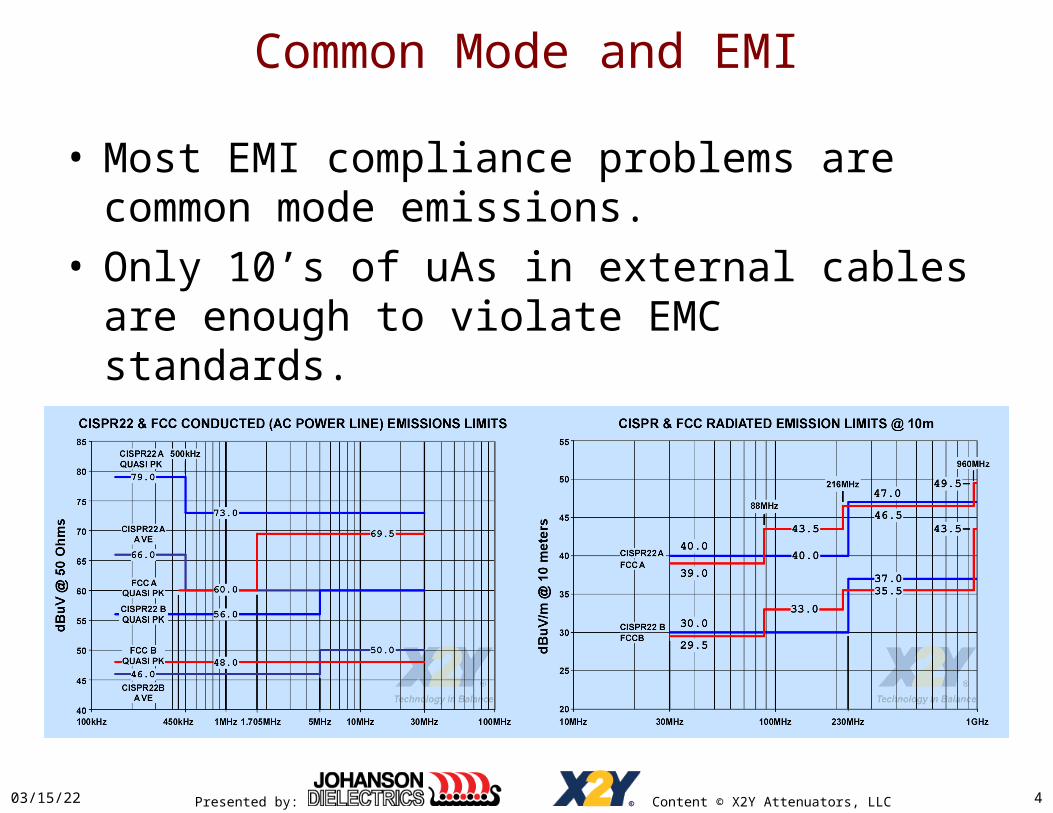
Common Mode and EMI
• Most EMI compliance problems are common mode emissions.
• Only 10’s of uAs in external cables are enough to violate EMC standards.
04/19/23 4

Presented by: Content © X2Y Attenuators, LLC
Common Mode Radiated Noise Model
• E field developed between any lead exiting a shielded enclosure and the enclosure outer skin radiates.
• Complementary H field couples to victim antennae.• Ability to radiate depends on:
– Power in the noise source– Coupling efficiency between the effective antenna structure and the
surrounding space• Leads and case form the antenna
04/19/23 5
Presented by: Content © X2Y Attenuators, LLC
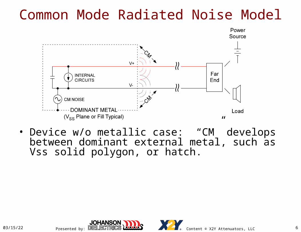
Common Mode Radiated Noise Model
• Device w/o metallic case: “CM” develops between dominant external metal, such as Vss solid polygon, or hatch.
04/19/23 6

Presented by: Content © X2Y Attenuators, LLC
Common Mode Radiated Noise Model
• Reduce radiation by:– Reducing potential between the case and leads, AND/OR– Reducing coupling efficiency to surrounding space
• Reduce antenna gain.• Mismatch source impedance to the antenna impedance.
04/19/23 7
Presented by: Content © X2Y Attenuators, LLC
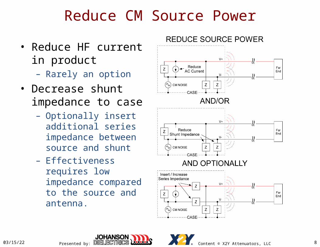
Reduce CM Source Power
04/19/23 8
• Reduce HF current in product– Rarely an option
• Decrease shunt impedance to case– Optionally insert additional
series impedance between source and shunt
– Effectiveness requires low impedance compared to the source and antenna.

Presented by: Content © X2Y Attenuators, LLC
Reduce Coupling
04/19/23 9
• Reduce antenna efficiency– Cable length– Cable routing / shielding
• Mismatch antenna impedance– Increase driving impedance
>> 377 Ohms*• Inserted Z effective when >>
ZSOURCE + ZANTENNA
– Decrease driving impedance << 377 Ohms*
• Inserted Z effective when << ZANTENNA
*Antenna impedance may be anywhere from 10’s to 100’s of OhmsTypically 100 – 180 Ohms

Presented by: Content © X2Y Attenuators, LLC
EMI Filter Attenuation
04/19/23 10
Presented by: Content © X2Y Attenuators, LLC
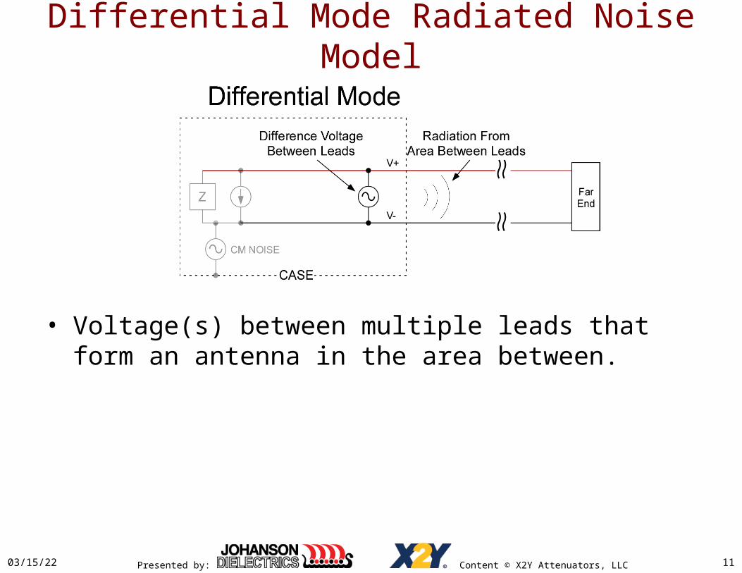
Differential Mode Radiated Noise Model
04/19/23 11
• Voltage(s) between multiple leads that form an antenna in the area between.

Presented by: Content © X2Y Attenuators, LLC
Mode Conversion
• Occurs when individual filters are not matched.• Differential signal energy converts into common-
mode energy.• Common-mode energy converts into differential
energy.• Avoid by matching filters throughout stop-band.• Not an emissions concern where signals do not exist
in the noise stop band.• Mode conversion is a susceptibility concern at all
frequencies.
04/19/23 12
Presented by: Content © X2Y Attenuators, LLC
Single Chokes / Beads as EMI Filters
04/19/23 13
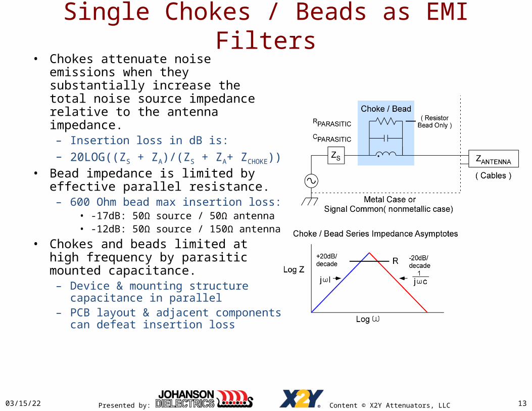
• Chokes attenuate noise emissions when they substantially increase the total noise source impedance relative to the antenna impedance. – Insertion loss in dB is:– 20LOG((ZS + ZA)/(ZS + ZA+ ZCHOKE))
• Bead impedance is limited by effective parallel resistance.– 600 Ohm bead max insertion loss:
• -17dB: 50Ω source / 50Ω antenna• -12dB: 50Ω source / 150Ω antenna
• Chokes and beads limited at high frequency by parasitic mounted capacitance.– Device & mounting structure
capacitance in parallel– PCB layout & adjacent components can
defeat insertion loss

Presented by: Content © X2Y Attenuators, LLC
CM Choke Mechanics• A CM choke couples chokes on a
common core– Usually two windings / core.– Coupling improves CM rejection
on each lead in the stop band, – CM chokes can pass differential
signals in the stop band.• A CM choke is a 1:1 transformer
where the primary and secondary are both driven.– Both windings act as both primary
and secondary.– Current through one winding
induces an opposing current in the other winding.
– For K close to 1.0, total effective CM impedance is:
• Z ≈ 2πF*LMAG
• 2X what two independent chokes with the same LMAG would yield.
04/19/23 14

Presented by: Content © X2Y Attenuators, LLC
CM Choke Mechanics• CM choke winding coupling DOES
NOT cancel all or even a high percentage of CM noise.
• CM chokes DO increase CM inductance up to 2X compared to each of two independent chokes of the same open circuit inductance rating.
• CM chokes DO cancel most core flux allowing much higher CM currents w/o saturation than two independent chokes of the same material and core size.– Allows DC and AC to pass as
differential currents w/o killing CM attenuating inductance
– Important to power filter applications that use chokes
• DC balance must be maintained in wiring and load.
04/19/23 15
Presented by: Content © X2Y Attenuators, LLC
CM Choke Mechanics
04/19/23 16
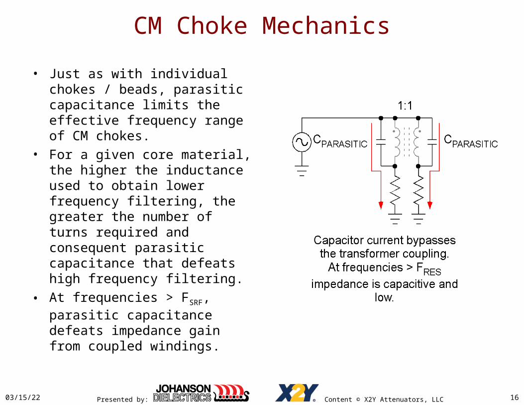
• Just as with individual chokes / beads, parasitic capacitance limits the effective frequency range of CM chokes.
• For a given core material, the higher the inductance used to obtain lower frequency filtering, the greater the number of turns required and consequent parasitic capacitance that defeats high frequency filtering.
• At frequencies > FSRF, parasitic capacitance defeats impedance gain from coupled windings.

Presented by: Content © X2Y Attenuators, LLC
Choke/Bead/CM Choke Bandstop
• Insertion loss declines past FSRF due to parasitic shunt capacitance.– Parasitic capacitance, noise
source impedance and lead antenna impedance define high frequency noise attenuation.
– Parasitic capacitance is combined effects of the CM Choke and the CM Choke PCB mount.
– Very small capacitances, < 1pF can have very big effects above 100MHz
– 1pF Limits 1GHz Insertion Loss:• -8dB: 50Ω source / 50Ω antenna• -5dB: 50Ω source / 150Ω antenna
• FSRF = 1/(2π(√(LCM*CPAR))
04/19/23 17

Presented by: Content © X2Y Attenuators, LLC
CM Chokes Winding Mismatch
04/19/23 18
• Mismatch between windings from mechanical manufacturing tolerance causes mode conversion.– A percentage of signal energy
converts to common mode, and vice-versa.
– This gives rise to EMC issues as well as immunity issues.
• Mismatch reduces the effective inductance in each leg.– LEFF ≈ LMAG * (1+KMATCH)
– 0.9 < KMATCH < 0.99

Presented by: Content © X2Y Attenuators, LLC
CMCs Stop Band Mode Conversion
• Parasitic capacitance and winding mismatch both defeat inductive cancellation in the stop band causing mode conversion.
• Not a major radiation concern where signal energy is negligible in the stop band.– Conditions under which a
shunt filter is a viable alternative.
04/19/23 19
Presented by: Content © X2Y Attenuators, LLC
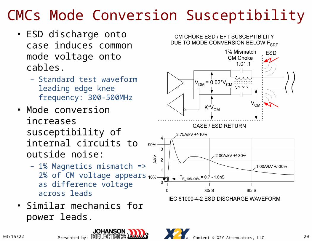
CMCs Mode Conversion Susceptibility• ESD discharge onto case
induces common mode voltage onto cables.– Standard test waveform
leading edge knee frequency: 300-500MHz
• Mode conversion increases susceptibility of internal circuits to outside noise:– 1% Magnetics mismatch =>
2% of CM voltage appears as difference voltage across leads
• Similar mechanics for power leads.
04/19/23 20
Presented by: Content © X2Y Attenuators, LLC
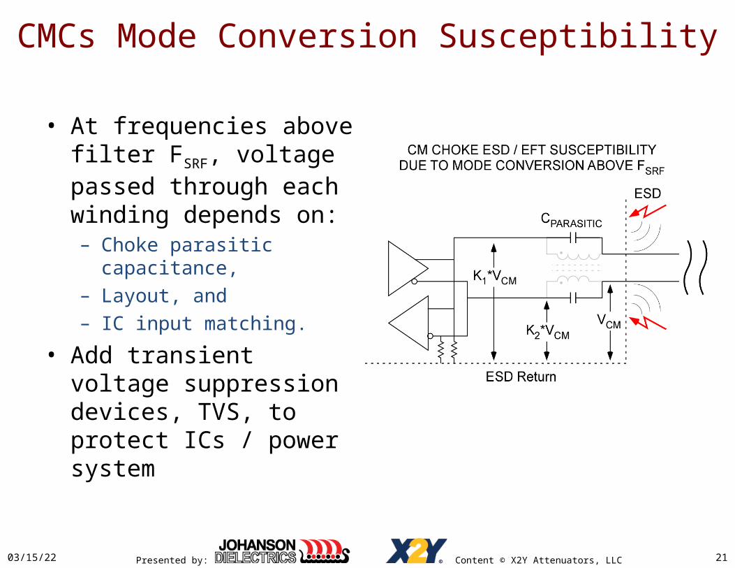
CMCs Mode Conversion Susceptibility
• At frequencies above filter FSRF, voltage passed through each winding depends on:– Choke parasitic capacitance,– Layout, and – IC input matching.
• Add transient voltage suppression devices, TVS, to protect ICs / power system
04/19/23 21

Presented by: Content © X2Y Attenuators, LLC
CM Chokes as EMI Filters
04/19/23 22
• CM chokes have one really good application:– Signals must be passed that
operate in the same frequency range as CM noise that must be suppressed.
– Mode conversion and winding mismatch is a major concern in these applications.
• Otherwise: CM chokes are: large, heavy, expensive, and subject to vibration induced failure.
• Estimating CM performance– Example: 4.7mH LCM, 3pF CPAR:– FSRF = 1.3MHz– ILdBMAX = 20LOG(100/8.4E6)– ≈ -52dB

Presented by: Content © X2Y Attenuators, LLC
X2Y® Capacitors, Nearly Ideal Shunts
• Two closely matched capacitors in one package.• Effects of temperature and voltage variation eliminated• Effect of ageing equal on both lines
• Very low inductance between terminals.
04/19/23 23
Presented by: Content © X2Y Attenuators, LLC
X2Y® Capacitors, Nearly Ideal Shunts
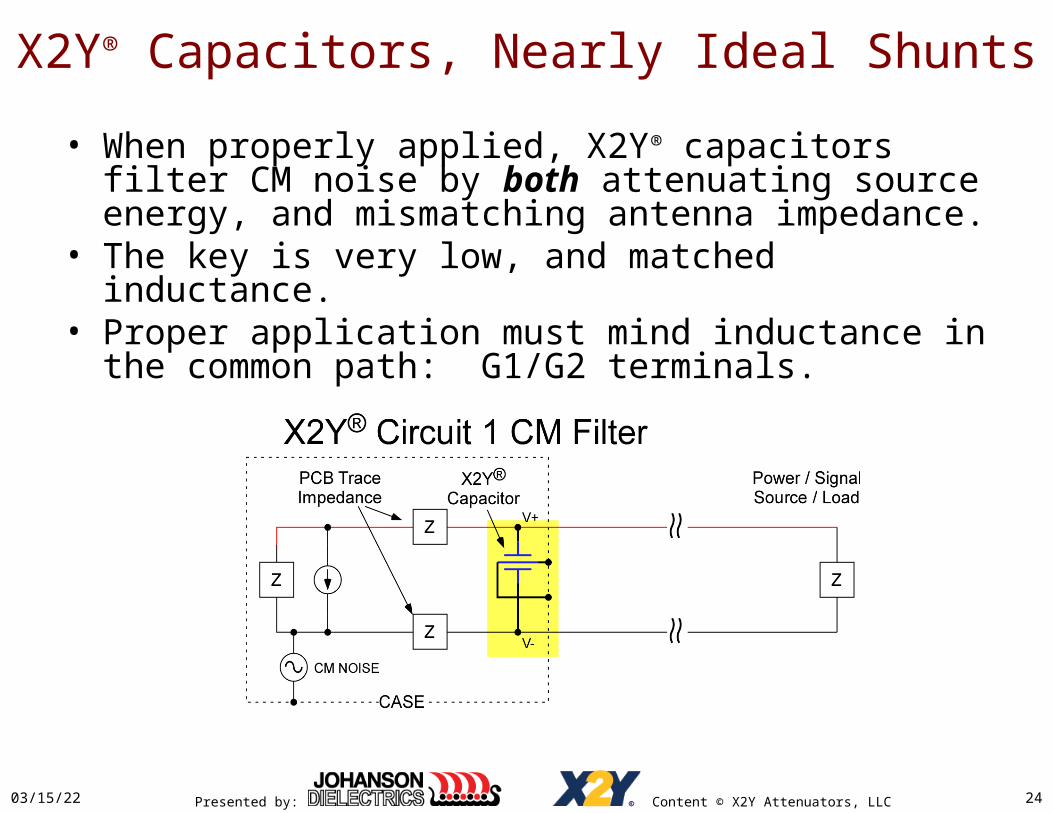
• When properly applied, X2Y® capacitors filter CM noise by both attenuating source energy, and mismatching antenna impedance.
• The key is very low, and matched inductance.• Proper application must mind inductance in the common
path: G1/G2 terminals.
04/19/23 24
Presented by: Content © X2Y Attenuators, LLC
X2Y® Capacitors, Nearly Ideal Shunts
04/19/23 25
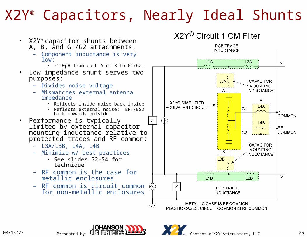
• X2Y® capacitor shunts between A, B, and G1/G2 attachments.
– Component inductance is very low:• ≈110pH from each A or B to G1/G2.
• Low impedance shunt serves two purposes:
– Divides noise voltage– Mismatches external antenna
impedance• Reflects inside noise back inside• Reflects external noise: EFT/ESD back
towards outside.• Performance is typically limited by
external capacitor mounting inductance relative to protected traces and RF common:
– L3A/L3B, L4A, L4B– Minimize w/ best practices
• See slides 52-54 for technique– RF common is the case for metallic
enclosures.– RF common is circuit common for
non-metallic enclosures

Presented by: Content © X2Y Attenuators, LLC
X2Y® Bandstop
04/19/23 26
• Insertion loss builds up to FSRF due to parallel capacitance.
• Insertion loss declines past FSRF due to parasitic common inductance.
• Y capacitor mismatch reduces insertion loss below FSRF.– Increases low frequency cut-
off by ≈ 2/(1 + KMATCH)– 0.9 < KMATCH < 0.99– Generally no concern

Presented by: Content © X2Y Attenuators, LLC
X2Y® vs. CM Choke Bandstop
04/19/23 27
X2Y®
Presented by: Content © X2Y Attenuators, LLC
X2Y® Bandstop
04/19/23 28
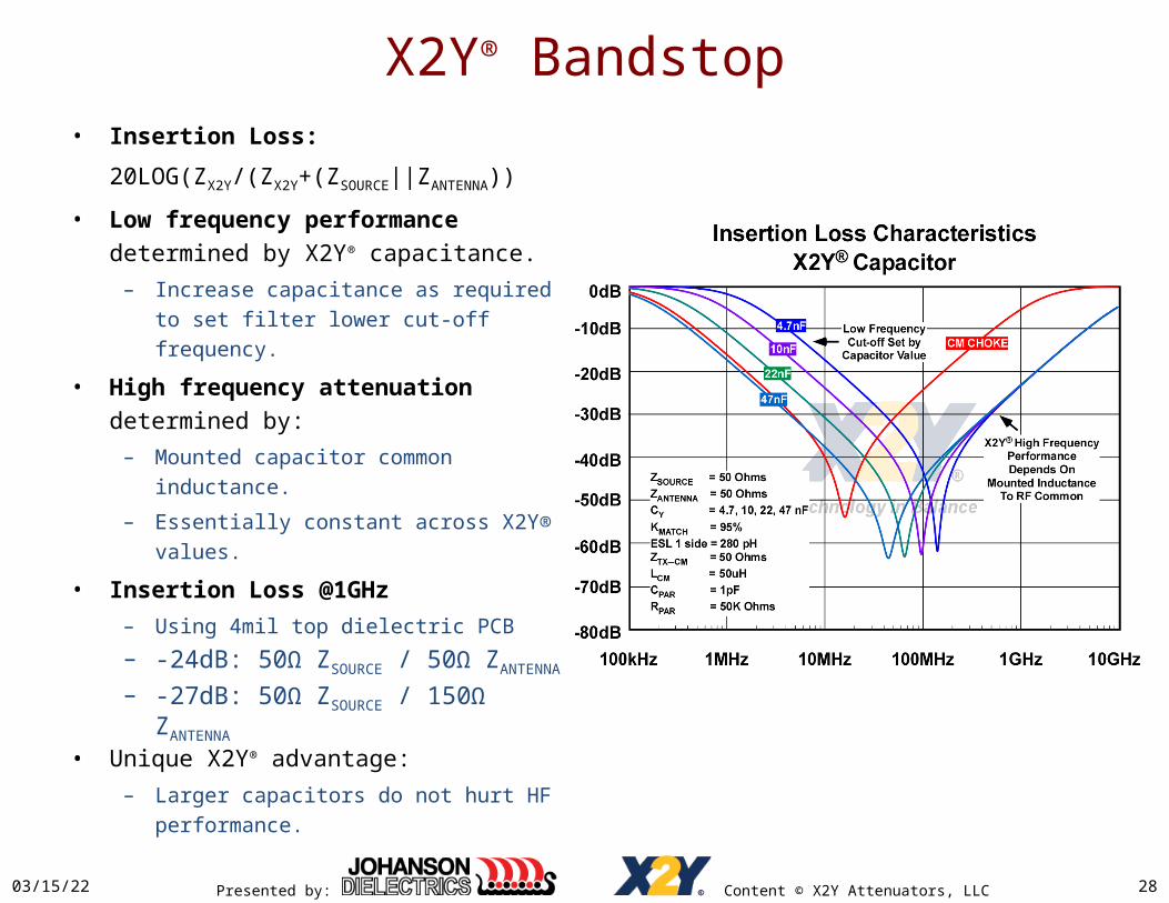
• Insertion Loss:
20LOG(ZX2Y/(ZX2Y+(ZSOURCE||ZANTENNA))
• Low frequency performance determined by X2Y® capacitance.
– Increase capacitance as required to set filter lower cut-off frequency.
• High frequency attenuation determined by:
– Mounted capacitor common inductance.
– Essentially constant across X2Y® values.
• Insertion Loss @1GHz – Using 4mil top dielectric PCB
– -24dB: 50Ω ZSOURCE / 50Ω ZANTENNA
– -27dB: 50Ω ZSOURCE / 150Ω ZANTENNA
• Unique X2Y® advantage:– Larger capacitors do not hurt HF
performance.
Presented by: Content © X2Y Attenuators, LLC
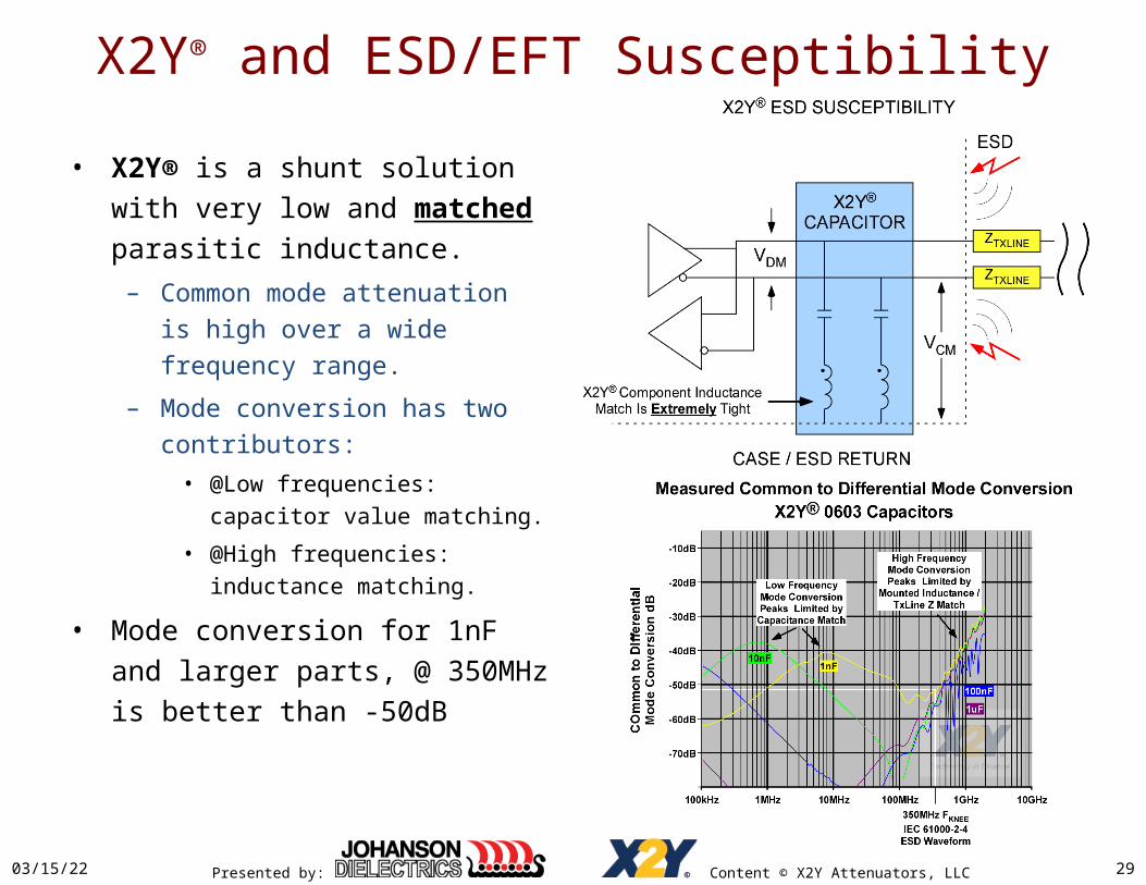
X2Y® and ESD/EFT Susceptibility
• X2Y® is a shunt solution with very low and matched parasitic inductance.
– Common mode attenuation is high over a wide frequency range.
– Mode conversion has two contributors:
• @Low frequencies: capacitor value matching.
• @High frequencies: inductance matching.
• Mode conversion for 1nF and larger parts, @ 350MHz is better than -50dB
04/19/23 29

Presented by: Content © X2Y Attenuators, LLC
X2Y® and ESD/EFT Susceptibility
04/19/23 30

Presented by: Content © X2Y Attenuators, LLC
Test Comparisons
04/19/23 31
• Test Setup– Agilent 85033D 3.5mm
Calibration Kit – Agilent E5071C ENA Network
Analyzer• 100 kHz - 8.5 GHz • Balanced measurements (4-
port option)
– DUT test board
Presented by: Content © X2Y Attenuators, LLC
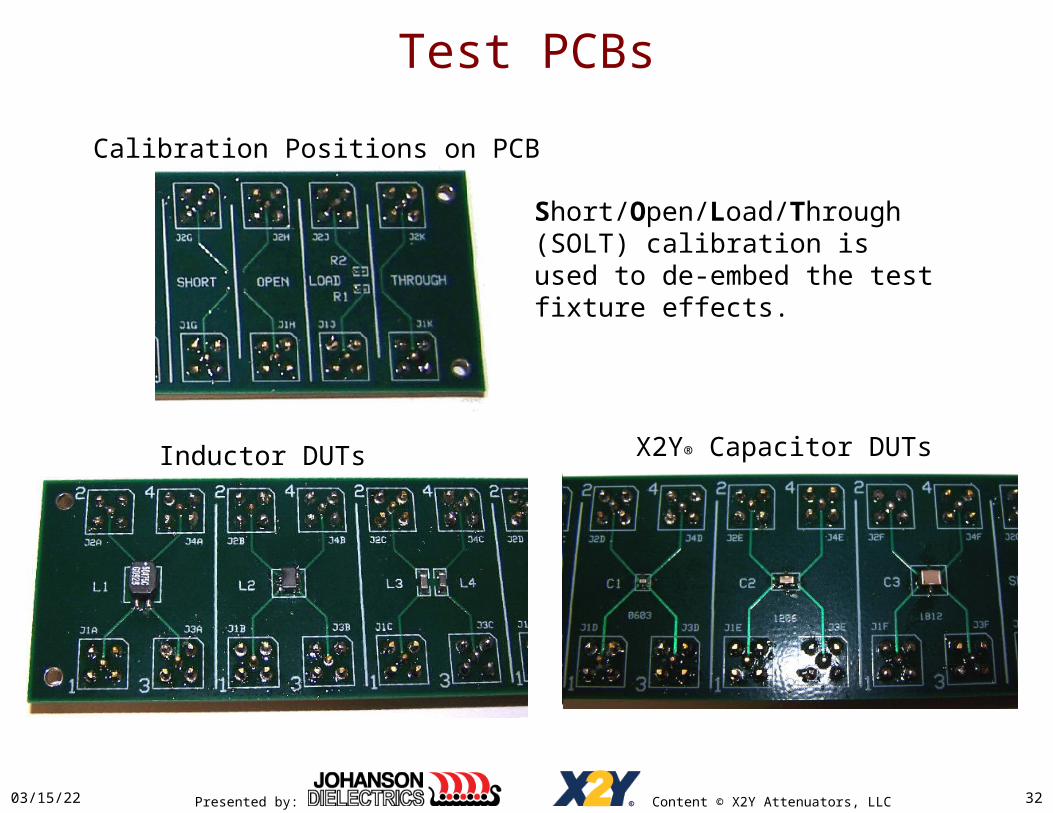
Test PCBs
04/19/23 32
Inductor DUTs X2Y® Capacitor DUTs
Calibration Positions on PCB
Short/Open/Load/Through (SOLT) calibration is used to de-embed the test fixture effects.
Presented by: Content © X2Y Attenuators, LLC
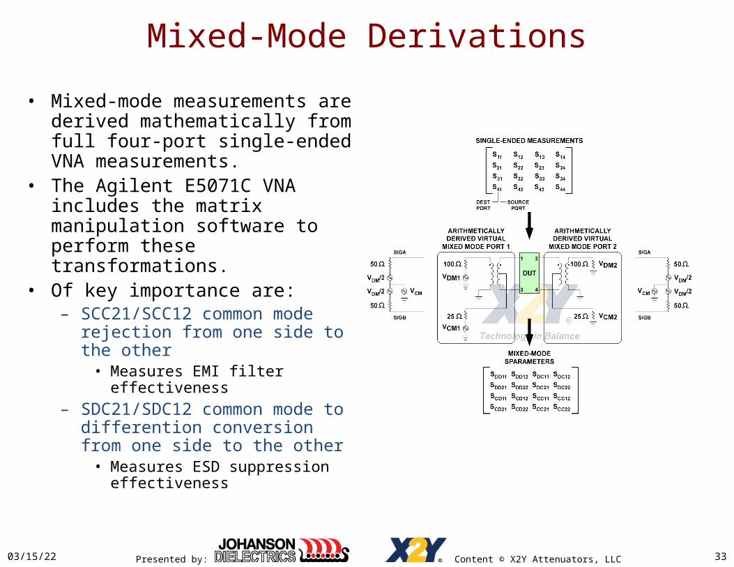
Mixed-Mode Derivations
• Mixed-mode measurements are derived mathematically from full four-port single-ended VNA measurements.
• The Agilent E5071C VNA includes the matrix manipulation software to perform these transformations.
• Of key importance are:– SCC21/SCC12 common mode
rejection from one side to the other
• Measures EMI filter effectiveness– SDC21/SDC12 common mode to
differention conversion from one side to the other
• Measures ESD suppression effectiveness
04/19/23 33

Presented by: Content © X2Y Attenuators, LLC
Mixed-Mode Derivations
04/19/23 34

Presented by: Content © X2Y Attenuators, LLC
• Goal: Determine the amount of common mode energy relative to grond driving Ports 1 and 3 that reaches Ports 2 and 4.– Indicates EMI suppression
performance
• Both Port 1 and Port 3 drive CM energy in parallel.– The two parallel 50Ω ports
appear as 25Ω on each side of the filter.
• Operation is symmetric:– SCC21 matches SCC12
04/19/23 35
Common Mode Derivation

Presented by: Content © X2Y Attenuators, LLC
Common Mode Derivation
04/19/23 36

Presented by: Content © X2Y Attenuators, LLC
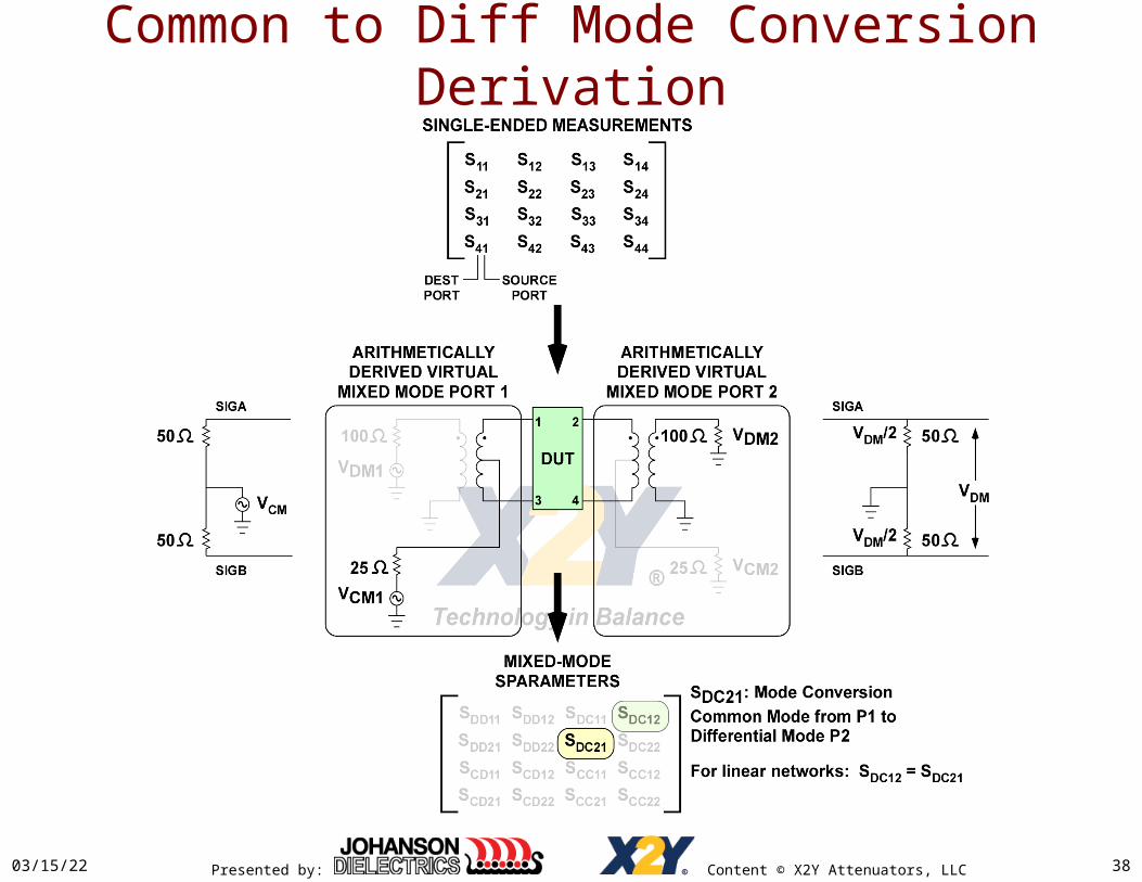
• Goal: Determine the amount of common mode noise from the external port that converts to differential energy across the internal ports.– Indicates immunity to
interference: cell phone, ESD, EFT, etc.
• CM input is two parallel 50Ω sources, 25Ω net.
• DM output appears across series 50Ω loads, 100Ω net.
• Operation is symmetric:– SDC21 matches SDC12
04/19/23 37
Common to Diff Mode Conversion Derivation
Presented by: Content © X2Y Attenuators, LLC
Common to Diff Mode Conversion Derivation
04/19/23 38

Presented by: Content © X2Y Attenuators, LLC
DUTComponent Size (mm)
L x W x H DC Current RatingPhoto
(not to scale)
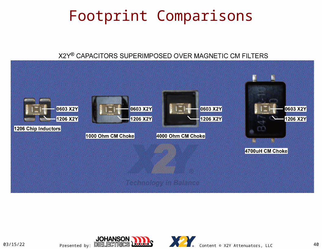
X2Y® 1812 4.4 x 3.2 x 2.3 In bypass, no current limit
X2Y® 1206 3.2 x 1.6 x 1.3 In bypass, no current limit
X2Y® 0603 1.6 x 0.8 x 0.7 In bypass, no current limit
(1) 4000 Ohm CMC 5 .0 x 3.6 x 4.3 200 mAmps
(1) 1000 Ohm CMC 5 .0 x 4.7 x 4.5 1500 mAmps
(1) 4.7 mH CMC A 9.0 x 6.0 x 4.8 400 mAmps
(1) 4.7mH CMC B 9.3 x 5.9 x 4.9 400 mAmps
(2) 1uH Chip Inductors (2) 3.2 x 1.6 x 0.85 1200 mAmps
(2) 120 Ohm Ferrite Beads (2) 3.2 x 1.6 x 1.1 3000 mAmps
(2) 600 Ohm Ferrite Beads (2) 3.2 x 1.6 x 1.1 3000 mAmps
Devices Under Test
04/19/23 39
Presented by: Content © X2Y Attenuators, LLC04/19/23 40
Footprint Comparisons
Presented by: Content © X2Y Attenuators, LLC
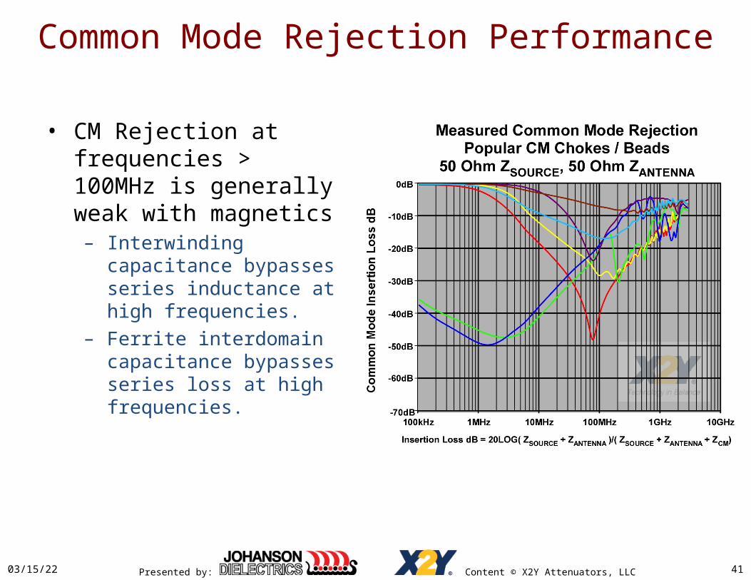
Common Mode Rejection Performance
• CM Rejection at frequencies > 100MHz is generally weak with magnetics– Interwinding capacitance
bypasses series inductance at high frequencies.
– Ferrite interdomain capacitance bypasses series loss at high frequencies.
04/19/23 41

Presented by: Content © X2Y Attenuators, LLC
Common Mode Rejection Performance
• Rejection ratio degrades for real antenna Z > 50Ω– 120 – 180 Ohms typical– 150Ω degrades by
• 6dB at high loss,• ≈ 3dB near 10dB
• Where ZCM >> ( ZS+ZA):– Loss ≈ 20LOG(ZS + ZA)/(ZCM)
– Increasing ZA from 50 to 150 doubles (ZS + ZA)
04/19/23 42
Presented by: Content © X2Y Attenuators, LLC
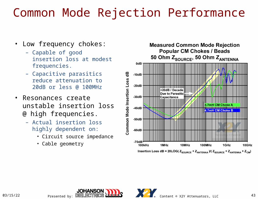
Common Mode Rejection Performance
• Low frequency chokes:– Capable of good insertion
loss at modest frequencies.– Capacitive parasitics reduce
attenuation to 20dB or less @ 100MHz
• Resonances create unstable insertion loss @ high frequencies.– Actual insertion loss highly
dependent on:• Circuit source impedance• Cable geometry
04/19/23 43

Presented by: Content © X2Y Attenuators, LLC
Common Mode Rejection Performance
• Complex HF resonances– High inductance /
capacitance chokes exhibit complex interactions with PCB traces, connectors, & cables @ high frequencies.
– As frequency moves between odd and even 1/4λ multiples of cable lengths, unterminated cable noise attenuation moves between local minima and maxima.
04/19/23 44
Presented by: Content © X2Y Attenuators, LLC
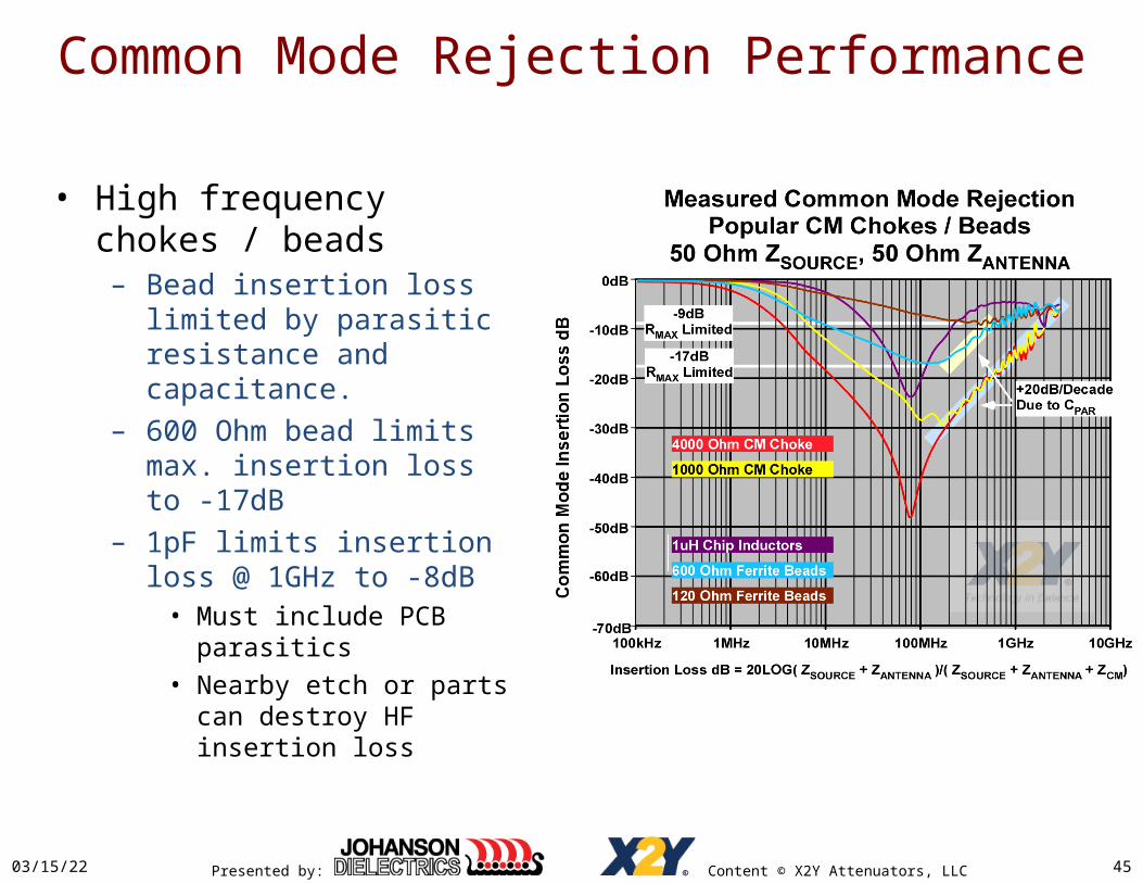
Common Mode Rejection Performance
• High frequency chokes / beads– Bead insertion loss limited by
parasitic resistance and capacitance.
– 600 Ohm bead limits max. insertion loss to -17dB
– 1pF limits insertion loss @ 1GHz to -8dB
• Must include PCB parasitics• Nearby etch or parts can
destroy HF insertion loss
04/19/23 45

Presented by: Content © X2Y Attenuators, LLC
Common Mode Rejection X2Y®
• Consistent high frequency performance independent of capacitance.– Mounted inductance controls– Linear decrease in noise
attenuation w/frequency– 0603 parts -24dB or better @ 1GHz
into 25 Ohm even mode impedance.
• Capacitor value only affects low frequency attenuation.– Larger capacitance values filter
lower frequencies
04/19/23 46

Presented by: Content © X2Y Attenuators, LLC
Common Mode Rejection X2Y®
• Rejection ratio improves for real antenna Z > 50Ω– 120Ω – 180Ω Ohms typical– 150Ω improves by
• 2.5dB at high loss, (>20dB)
• Where ZX2Y << ( ZS||ZA):– Loss ≈ 20LOG(ZX2Y)/(ZS||ZA)
– Increasing ZA from 50Ω VNA port to 150Ω practical antenna value decreases (ZS||ZA) by 0.75:1.
04/19/23 47
Presented by: Content © X2Y Attenuators, LLC
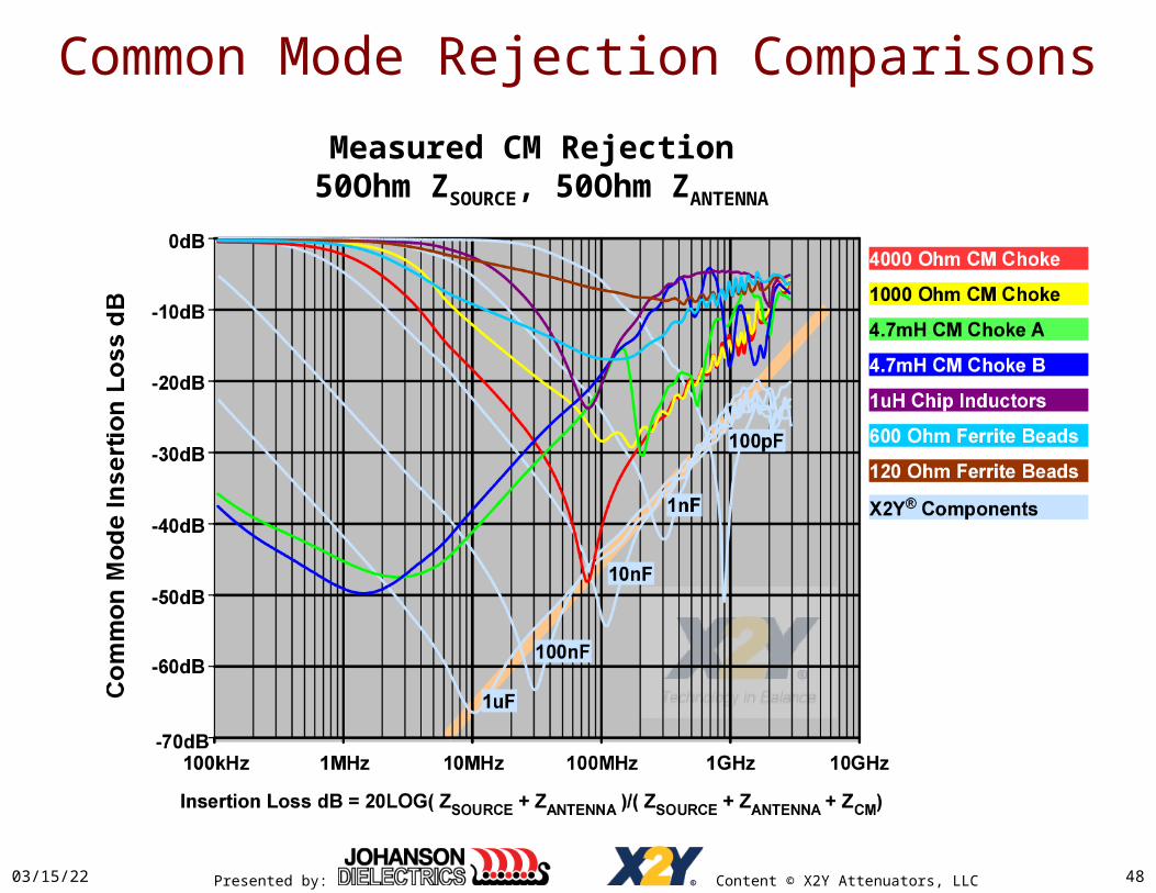
Common Mode Rejection Comparisons
04/19/23 48
Measured CM Rejection 50Ohm ZSOURCE, 50Ohm ZANTENNA

Presented by: Content © X2Y Attenuators, LLC
Common Mode Rejection Comparisons
04/19/23 49
Measured CM Rejection 50Ohm ZSOURCE, 150Ohm ZANTENNA

Presented by: Content © X2Y Attenuators, LLC
Common Mode Rejection ComparisonsLoad Antenna Impedance
• X2Y® capacitors significantly outperform CM chokes using 50Ω VNA ports
• X2Y® capacitors exhibit even greater advantage in real applications using typical 150Ω antennae.
04/19/23 50

Presented by: Content © X2Y Attenuators, LLC
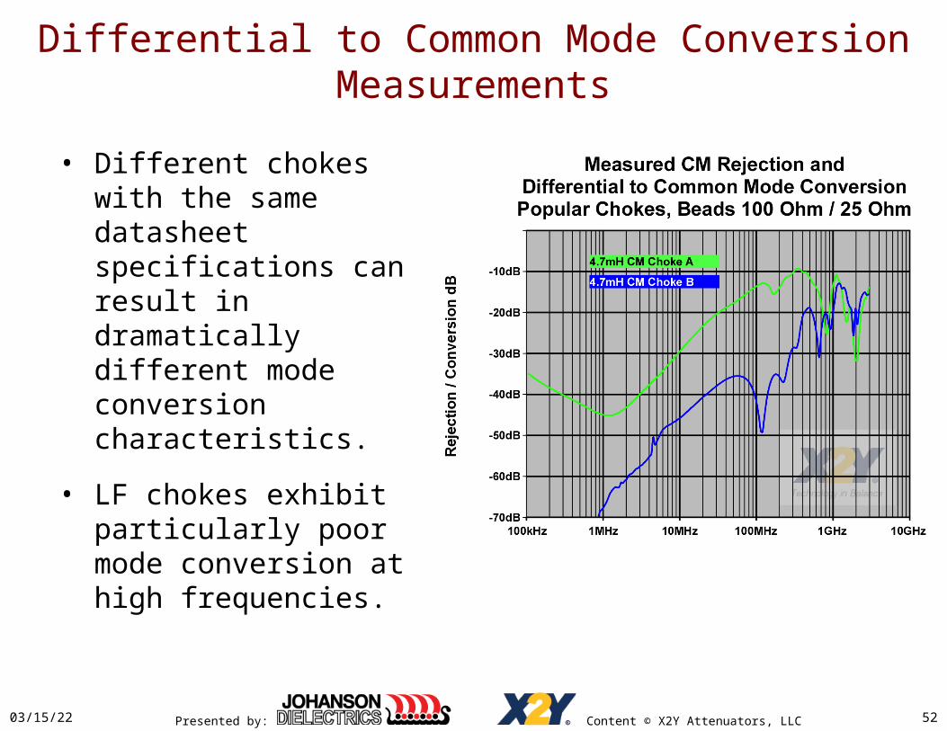
Differential to Common Mode Conversion Measurements
• Parasitic capacitive coupling in CM chokes results in significant mode conversion at even modest frequencies.– Typical ≈ -35dB @ 350MHz
(FKNEE IEC 61000-2-4)
– Some devices are much worse
• Results in weak ESD immunity.
04/19/23 51
Presented by: Content © X2Y Attenuators, LLC
Differential to Common Mode Conversion Measurements
• Different chokes with the same datasheet specifications can result in dramatically different mode conversion characteristics.
• LF chokes exhibit particularly poor mode conversion at high frequencies.
04/19/23 52

Presented by: Content © X2Y Attenuators, LLC
• Ferrite beads and smaller value chokes improve mode conversion, but exhibit poorer common mode rejection
04/19/23 53
Differential to Common Mode Conversion Measurements

Presented by: Content © X2Y Attenuators, LLC
• X2Y® capacitors convert a small amount of differential energy to common mode due to finite tolerance mismatches.
• Conversion is -52dB @ 350MHz, -40dB @1GHz– 17dB better than typical
CM choke / bead solution
04/19/23 54
Measured Differential to Common Mode Conversion
X2Y® 0603 Capacitors
Differential to Common Mode Conversion Measurements
Presented by: Content © X2Y Attenuators, LLC
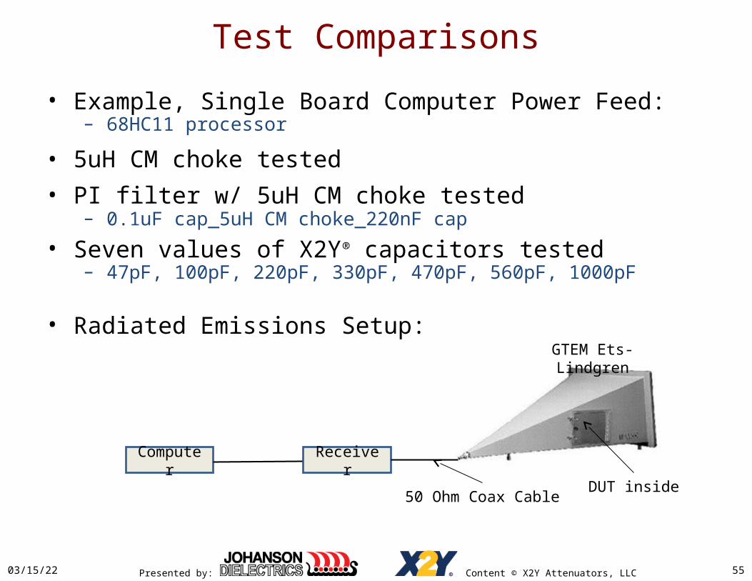
Test Comparisons
• Example, Single Board Computer Power Feed:– 68HC11 processor
• 5uH CM choke tested• PI filter w/ 5uH CM choke tested
– 0.1uF cap_5uH CM choke_220nF cap
• Seven values of X2Y® capacitors tested– 47pF, 100pF, 220pF, 330pF, 470pF, 560pF, 1000pF
• Radiated Emissions Setup:
04/19/23 55
Receiver
GTEM Ets-Lindgren
DUT inside50 Ohm Coax Cable
Computer
Presented by: Content © X2Y Attenuators, LLC
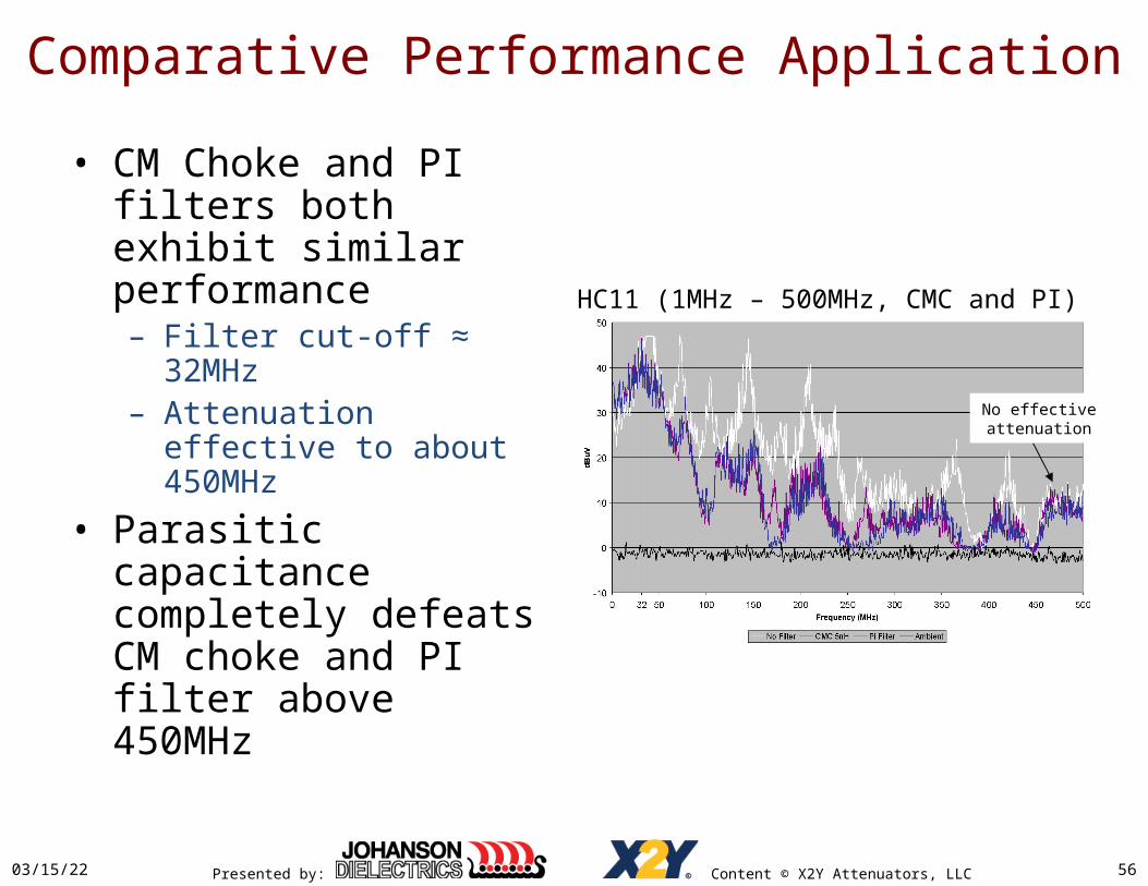
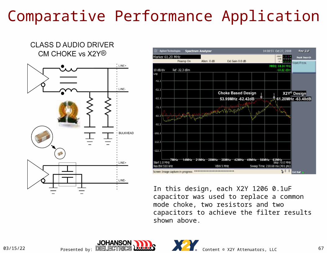
Comparative Performance Application
04/19/23 56
No effectiveattenuation
HC11 (1MHz – 500MHz, CMC and PI)
• CM Choke and PI filters both exhibit similar performance– Filter cut-off ≈ 32MHz– Attenuation effective to
about 450MHz
• Parasitic capacitance completely defeats CM choke and PI filter above 450MHz

Presented by: Content © X2Y Attenuators, LLC04/19/23 57
No effectiveattenuation
Comparative Performance Application
1MHz – 500MHz CMC and PI

Presented by: Content © X2Y Attenuators, LLC
Comparative Performance Application
04/19/23 58
47pF Superior to CM chokeAbove 300MHz
HC11 (50MHz –1GHz, 47pF X2Y)50MHz – 1GHz, 47pF X2Y®
GSM ambient

Presented by: Content © X2Y Attenuators, LLC
Comparative Performance Application
04/19/23 59
100pF Superior to CM chokeAbove 150MHz
HC11 (50MHz –1GHz, 100pF X2Y)50MHz – 1GHz, 100pF X2Y®

Presented by: Content © X2Y Attenuators, LLC
Comparative Performance Application
04/19/23 60
220pF Comparable/Superior to CM chokeAbove 50MHz
HC11 (50MHz –1GHz, 220pF X2Y)50MHz – 1GHz, 220pF X2Y®

Presented by: Content © X2Y Attenuators, LLC
Comparative Performance Application
04/19/23 61
Larger X2Y® capacitor valuesExtend low frequency attenuation
HC11 (50MHz –1GHz, 330pF X2Y)50MHz – 1GHz, 330pF X2Y®

Presented by: Content © X2Y Attenuators, LLC
Comparative Performance Application
04/19/23 62
HC11 (50MHz –1GHz, 470pF X2Y)50MHz – 1GHz, 470pF X2Y®

Presented by: Content © X2Y Attenuators, LLC
Comparative Performance Application
04/19/23 63
HC11 (50MHz –1GHz, 560pF X2Y)50MHz – 1GHz, 560pF X2Y®

Presented by: Content © X2Y Attenuators, LLC
Comparative Performance Application
04/19/23 64
HC11 (50MHz –1GHz, 1000pF X2Y)1MHz – 500MHz, 1,000pF X2Y®
X2Y® 1,000pF high frequency radiated emissions vastly better then
CMC or PI

Presented by: Content © X2Y Attenuators, LLC
Comparative Performance Application
04/19/23 65
High frequency perfomanceis nearly identical between
capacitor values.
50MHz – 1GHz, 47pF & 1,000pF X2Y®

Presented by: Content © X2Y Attenuators, LLC
Comparative Performance Summary
• X2Y® capacitors effective to 1GHz and beyond.• Capacitance value determines low frequency
rejection.• Very small X2Y® caps (47pF) superior solution vs. CM
chokes or PI filters down to 300MHz.• 470pF and larger X2Y® caps superior over all
frequencies.• 1,000pF X2Y® vastly better RE than 5µH CM choke or
PI filter
04/19/23 66
Presented by: Content © X2Y Attenuators, LLC
Comparative Performance Application
In this design, each X2Y 1206 0.1uF capacitor was used to replace a common mode choke, two resistors and two capacitors to achieve the filter results shown above.
04/19/23 67
Presented by: Content © X2Y Attenuators, LLC
X2Y® Capacitor Selection
• X2Y® capacitors operate as shunts.– Attenuate all energy above cut-off frequency– Select to pass required signal energy / block offensive HF
noise.– Use capacitance value that is large enough to attenuate
effectively to lowest noise frequency, but no larger than necessary.
• Four recommended selection methods:– 1. Pass a required signal rise / fall time.– 2. Pass a required signal rise / fall time as a bit interval %.– 3. Cut-off HF noise at a specific frequency.– 4. Substitute for a specific CM choke.
04/19/23 68

Presented by: Content © X2Y Attenuators, LLC
X2Y® Capacitor Selection Method 1.
• Use Acceptable Signal Rise and Fall Times• Establish TRISE / TFALL
– C <= TRISE_10%_90% _MIN/(2.2*ZSOURCE)
• Example: CAN BUS 1Mbps, 120 Ohm– TRISE_10%_90% <= 50ns
– ZSOURCE = 120 Ohms / 2 (Loosely coupled diff pair) = 60 Ohms
– CMAX <= 50ns/(2.2*60 Ohms)
– CMAX <= 380pF
– Recommended value = 330pF– TRISE_10%_90% <= 44ns
04/19/23 69

Presented by: Content © X2Y Attenuators, LLC
X2Y® Capacitor Selection Method 2.
• Pass Signal Rise and Fall Times Based on Signal Bit Rate and % Allowable TR / TF
• TRISE_10%_90% / TFALL_90%_10% < 5-10% of bit period is usually OK– 5%
• C <= 1/(44*Bit_Frequency*ZSOURCE)
• CAN BUS– C <= 1/(44*1MHz*60 Ohms) <= 380pF
– 10%• C <= 1/(22*Freq*ZSOURCE)
04/19/23 70
Presented by: Content © X2Y Attenuators, LLC
X2Y® Capacitor Selection Method 3.
• Cut Noise Down to a Specific Low Frequency• Noise cut-off frequency FCO is known, source
impedance ZSOURCE and antenna impedance ZANTENNA.– C => 1/(2π*FCO*(ZSOURCE|| ZANTENNA)
• Example: Switching power supply harmonic suppression– FCO = 200kHz– ZSOURCE = transmission line impedance 10 Ohm– ZANTENNA = 150 Ohm– CMIN >= 1/(2π*200kHz*10||150 Ohm) = 1/1.26E7 = 80nF– Recommended minimum value = 100nF
• Use larger capacitances for lower frequencies and/or lower impedances.
04/19/23 71

Presented by: Content © X2Y Attenuators, LLC
X2Y® Capacitor Selection Method 4.
• Substitute for known CM Choke at a known source and antenna impedance:– Match choke low frequency insertion loss:
• CX2Y >= LCM/(ZSOURCE*ZANTENNA)
• LCM is the coupled inductance.– Typically ≈ 2X Inductance measured with second winding open
– If ZSOURCE and/or ZANTENNA are not known:• Assume 50 Ohms for ZSOURCE
• Assume 100 Ohms for ZANTENNA
• Yields a conservative result that will perform equal or better in a real application
04/19/23 72

Presented by: Content © X2Y Attenuators, LLC
X2Y® Capacitor Selection Method 4.
• Example– 50Ω ZSOURCE
– 100Ω ZANTENNA
– 50uH CM Choke
• CX2Y = 50uH/(50Ω*100Ω)• 10nF rated value• 4 mil dielectric to ground
• X2Y® matches LF performance
• X2Y® provides > 20dB insertion loss improvement @ 1GHz
04/19/23 73

Presented by: Content © X2Y Attenuators, LLC
X2Y® Capacitors, Best Practices Circuit 1
04/19/23 74
• Performance is typically limited by external capacitor wiring inductance:– L3A/L3B, L4A, L4B
• Maximize performance by minimizing L3x, and L4x inductances.– Follow X2Y® mounting
guidelines.• L1x, and L2x inductance is OK and
even beneficial when balanced.– Limitation on L2 is to keep
connection close to egress.

Presented by: Content © X2Y Attenuators, LLC04/19/23 75
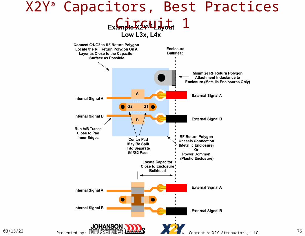
• Locate capacitors close to bulkhead• Minimize, L3A, L3B
– Connect A, B pad connections near base of pads
• Minimize L4A, L4B:– Connect G1/G2 to RF return polygon
on an internal PCB layer as close to the capacitor surface as possible.
• Chassis for metal enclosures• Power common plane for
plastic enclosures.• 12mil vs 4mil upper dielectric
costs about 3dB insertion loss @1GHz
– Metal enclosures attach RF return polygon to chassis w/ low inductance
• Multiple attachments along PCB edge recommended
X2Y® Capacitors, Best Practices Circuit 1
Presented by: Content © X2Y Attenuators, LLC04/19/23 76
X2Y® Capacitors, Best Practices Circuit 1
Presented by: Content © X2Y Attenuators, LLC
X2Y® Capacitors, Mounting Errors
04/19/23 77
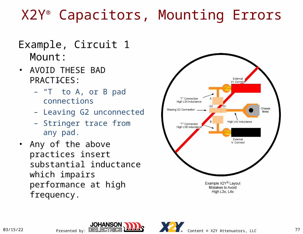
Example, Circuit 1 Mount:• AVOID THESE BAD PRACTICES:
– “T” to A, or B pad connections– Leaving G2 unconnected– Stringer trace from any pad.
• Any of the above practices insert substantial inductance which impairs performance at high frequency.
Presented by: Content © X2Y Attenuators, LLC
Summary
• Most EMI problems are Common Mode.
• Reduce common mode by attenuating driving voltage and/or mismatching antenna impedance.– Properly mounted X2Y® caps do both
• Series elements suffer from mode conversion and/or poor CM insertion loss at high frequencies.
• X2Y® capacitors maintain good CM insertion loss and mode conversion figures into the GHz.
04/19/23 78
Presented by: Content © X2Y Attenuators, LLC
Summary• Magnetics noise suppression degrades as actual circuit
antenna impedance increases above measuring instrument 50Ω impedance.– Real w/150Ω antenna is typically 3dB worse than 50Ω VNA
measurement
• X2Y® noise suppression improves as actual circuit antenna impedance increases above measuring instrument 50Ω impedance.– Real w/150Ω antenna is 3dB better than 50Ω VNA
• X2Y® capacitor values may be easily selected to filter EMI based on any:– Required signal pass-band (sets max capacitor value),– Required noise stop-band (sets min capacitor value),– Improved replacement for existing CM magnetics
04/19/23 79
Presented by: Content © X2Y Attenuators, LLC
or
Summary
04/19/23 80
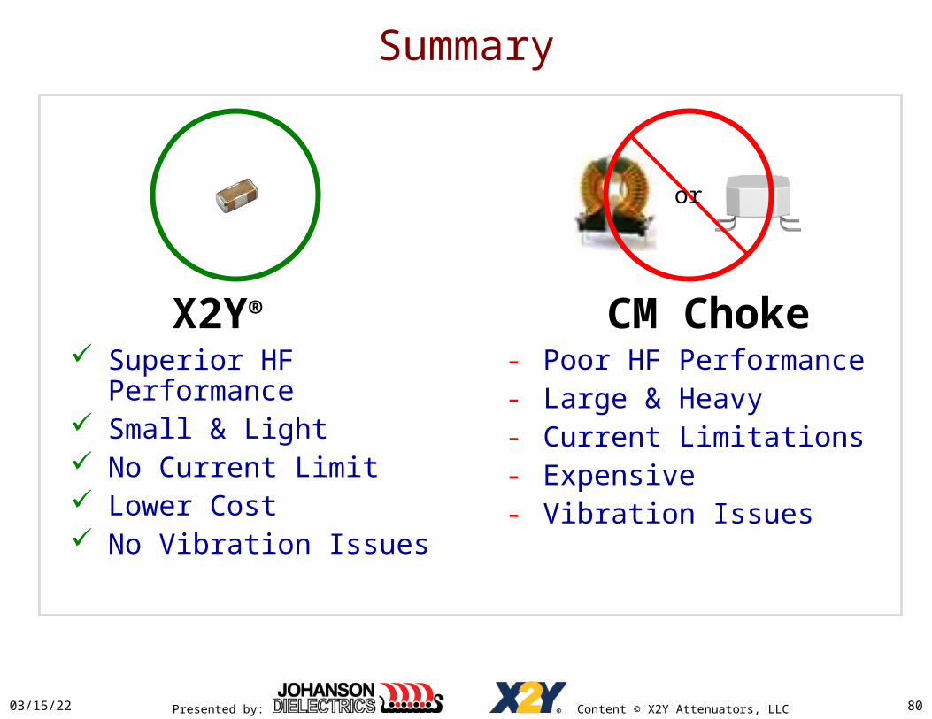
X2Y® Superior HF Performance Small & Light No Current Limit Lower Cost No Vibration Issues
CM Choke- Poor HF Performance- Large & Heavy- Current Limitations- Expensive- Vibration Issues

Presented by: Content © X2Y Attenuators, LLC
Thank You !
www.johansondielectrics.com www.x2y.com