Embed Size (px)
Citation preview

15
Pressure and Temperature Microsensor Based on Surface Acoustic Wave in TPMS
Tianli Li1, Hong Hu2, Gang Xu1, Kemin Zhu1 and Licun Fang1 1Shenzhen University,
2Harbin Institute of Technology Shenzhen Graduate School China
1. Introduction
The tire pressure monitoring system (TPMS) can not only make the driver more safety, but also save fuel and protect the tire. Tire safety is attracting the driver's attention, the United States had developed laws to enforce the TPMS installation in the car. In this paper, the basic structure and the implement method of TPMS are introduced. The SAW theory and some surface acoustic wave (SAW) temperature and pressure sensors which suit for the TPMS application are illustrated, because the passive sensor is becoming the focus in the TPMS research field. Passive SAW sensor is the good choice for TPMS, according to its wireless, passive, small size, zero age rate etc. The wireless passive SAW TPMS is one of the most important research direction. For the typical applications of automotive TPMS, a novel microsensor based on SAW is reported in this paper. The kernel structure and design theory of this sensor with a single sensing unit are introduced. With the theory of SAW delay line, the effects of temperature and pressure on the microsensor were able to be reflected by the variations of the radio frequency (RF) echo signals. The accurately measured temperature and pressure values were obtained by using of a weight factor in the data process. The excellent agreement between the pressure and temperature results measured by the sensor and the direct measurement data is presented. The practical results in the certain ranges of pressure and temperature demonstrated that the microsensor is able to measure temperature (0kPa-200kPa) and pressure (20ºC-100ºC) at the same time. For SAW sensors the temperature measurement accuracy can reach 0.05ºC, and the pressure measurement accuracy can reach 7.2kPa. In the areas of TPMS, where reliability and durability are really demanding, the reported microsensor has its practicability and potential market with its advantages of simple structure, and wireless and passive working mode.
2. Background of tire pressure monitoring system
Security, economy and comfort of the automobile are the basic demands for the customers. Automakers have made significant improvements on vehicle safety in recent years, such as Antilock-Braking System (ABS), Traction Control System (TCS), 4 Wheel Steering (4WS) and Electronic-Stability Program (ESP) in today’s vehicle products. The applications of these technologies can contribute to highway-accident reduction, i.e., ensuring that the vehicle is in good condition for use.
Source: Acoustic Waves, Book edited by: Don W. Dissanayake, ISBN 978-953-307-111-4, pp. 466, September 2010, Sciyo, Croatia, downloaded from SCIYO.COM
www.intechopen.com

Acoustic Waves
342
Tire condition is one of the greatest contributors to safety. Paradoxically, studies in the United States reveal that although about 85% of the population recognizes the importance of maintaining properly inflated tires, most drivers wait until the vehicle’s service interval to have a car service person check the tires. Tire pressure may have an influence on any crash that involves braking, since low tire pressure can result in increased stopping distances. Road safety can cost as many as 40,000 lives every year across Europe. With vehicle-service intervals that now approach 50,000 km for some models, lack of attention to routine maintenance clearly creates unnecessary hazards. Under-pressure tires sometimes are not easy to be observed, because the circumference changes relatively little from 1 to 3 bar of internal pressure, and 30% under-pressure is nearly undetectable to a casual observer. Fig. 1 shows that it is difficult for an ordinary driver to tell the difference between two tires with different pressures (David, 2004). A study from the U.S. DoT (Department of Transportation) that surveyed 11,530 vehicles nationwide showed that 27% of passenger cars and 33% of light trucks operated with one or more substantially under-pressure tires. The consequences of tire under-pressure are increased fuel costs, reduced tire and tread life, tire blowouts and tread separation, dual wheel assembly problems and additional high temperature problems. Incorrect tire pressure can affect the handling, braking and stability of a vehicle and, according to industry statistics, may be responsible for hundreds of thousands of accidents each year. One of the automotive safety requirements that is becoming more prominent is the use of TPMS, which alerts the driver when tire pressure or temperature drops to an unsafe level, just like the warning lights that signal low fuel level.
Fig. 1. A fully inflated tire (left) and one with only 70% pressure (right) (David, 2004)
Unsurprisingly, vehicle manufacturers and regulatory authorities are keenly interested in techniques for TPMS. This fits to visions and strategies of vehicle manufacturers, automotive suppliers and tire manufacturers. This development was mainly driven by vehicle manufacturers. Although automakers recognized this requirement as long ago as 1970, but a cost-effective solution simply wasn’t available at that time. Today’s technologies can satisfy the requirement in an affordable way, so the U.S. DoT mandates that most vehicles built from now on should carry a TPMS, and all vehicles sold in the United States must be equipped with TPMS starting from 2007. Key legislation appeared in the TREAD (Transportation Recall Enhancement, Accountability, and Documentation) Act of November 2001, with main support work coming from the U.S. NHTSA (National Highway Traffic Safety Administration).
www.intechopen.com

Pressure and Temperature Microsensor Based on Surface Acoustic Wave in TPMS
343
TPMS not only provides enhanced safety for drivers and passengers, offers more convenience, but also eliminates guesswork to the tire pressure and temperature. TPMS will warn drivers when a tire is abnormal, preventing tire damage and subsequent accidents. TPMS will not only help prevent accidents, but save as much as $1.7 billion each year in fuel and vehicle maintenance costs, as under-pressure tires shorten tire life and increase fuel consumption, according to NHTSA. TPMS meets the demand for improved vehicle safety, performance, reliability and fuel efficiency. The future business for TPMS is set to be huge. Consultant firm strategy analytics expects TPMS to become the fastest-growing automotive electronics system, reaching 30 million units by 2010.
3. TPMS implementation methods
TPMS turns tire pressure checking into an automatic process. TPMS can measure the tire pressure and temperature parameters automatically utilizing sensors inside the tires at any time. According to the measurement results, TPMS can give drivers an alarm when the pressure or temperature in tires is abnormal so that the drivers can take the appropriate corrective action (Wang et al., 2003). In this way, the tire pressure and temperature are kept at normal level, and the resistance of tire rolling is reduced, tire abrasion and fuel consumption are decreased, tire’s service-life is increased, so the economy and safety of the car are improved greatly. Currently, two methods of TPMS are being developed, which are indirect TPMS and direct TPMS (David, 2004). Direct TPMS measures the tire pressure and temperature through the sensors which are installed in the tires. Indirect TPMS obtains tire pressure through external software algorithms by analyze rotational speed of each wheel.
3.1 Indirect TPMS Indirect methods use wheel speed sensors and ECU of the ABS system which are already existed in the car to infer low tire pressure by looking for a wheel that is spinning faster than the others. The technique works by comparing the rotational speed of each wheel in normal driving mode, since a tire’s rolling radius depends on the air pressure inside. This method minimizes implementation cost by taking advantage of the fact that ABS appears in virtually every vehicle product. However, the radius also depends on many other variables, which do not make ABS-based TPMS very reliable. Problems that might occur using indirect TPMS are listed as follows: 1. The system needs calibration before it can sense different tire conditions. In addition,
tire changing requires resetting the system to relearn the dynamic relationship between each wheel.
2. In a test carried out by the U.S. DoT, an indirect TPMS didn’t detect some kinds of low tire pressures when two low-pressure tires were on the same side or axle, or all four tires were under-pressure to a similar degree.
3. Slip at the wheels disturbs the pressure-sensing algorithm. 4. Speed, acceleration, uneven tire wear and production tolerances affect rolling radius. 5. The system is unable to detect tire deflation of typically less than 30%.
3.2 Direct TPMS The direct TPMS utilizes sensors installed inside tires to measure and feedback the pressures and temperatures directly. Wireless technologies for data transmission have to be used,
www.intechopen.com

Acoustic Waves
344
because the wheel is a rotating system which can’t be connected by a wire. The direct TPMS uses RF technology for transmitting sensor data to the vehicle. The most commonly used frequency for transmitting the measured tire information to the receiver is about 433 MHz. This frequency can be freely used in Europe. In the United States a similar license-free frequency is 315 MHz. The receivers consist of antenna, processor, memory and a user interface. Products for the aftermarket usually have a receiver that contains all of these components in one box. The direct TPMS can be classified as three classes according to the sensor installation place. First, clamp-on-rim sensors can be installed on the well bed of the rim with a stainless steel clamp, which is showed in the left of Fig. 2. This fixing method can usually be used in aftermarket products, when the same product must suit a large variety of cars. Secondly, valve-attached sensors can be fixed on the bottom end of the tire valve, as shown in the middle of Fig. 2. In this case, the sensor is actually located on the very same spot as when using a clamp on the rim well bed. Different rims require different valves, which means that this fixing method is better for the original equipment market, where it only has to fit a specific car model with limited variety of wheel types. Thirdly, valve-cap-integrated sensors are to try and squeeze the sensor electronics inside a valve cap, which is showed in the right of Fig.2. This fixing method is easy and suitable for aftermarket and especially heavy vehicles, but this method may make the tire sensor more dangerous for exposure outside.
Fig. 2. Picture from three types
There are two types of direct TPMS according to the power method of the sensor. One type uses the active sensors, that is to say the TPMS contains a component for electric power supply by batteries. The main components of an active battery operated in TPMS are battery, processor, memory, sensors, radio component, and antenna. Some of these components are usually integrated on a single chip to save weight and space and to reduce power consumption. The battery is the most problematic component. It limits the operation time of the sensor, and the existing batteries have also temperature limitations. In very cold or high temperature they may not work properly or may even be destroyed completely. The other type uses the passive sensors, that is to say the sensor needn’t use battery as a power, the sensor can get the working energy from the others methods such as the RF singles or an generator near the sensors.
www.intechopen.com
Pressure and Temperature Microsensor Based on Surface Acoustic Wave in TPMS
345
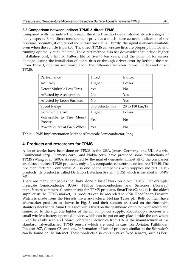
3.3 Comparison between indirect TPMS & direct TPMS Compared with the indirect approach, the direct method demonstrated its advantages in many aspects. First, direct measurement provides a much more accurate indication of tire pressure. Secondly, it can report individual tire status. Thirdly, the signal is always available even when the vehicle is parked. The direct TPMS can ensure tires are properly inflated and running optimally at all the time. The direct method also has downsides that include higher installation cost, a limited battery life of five to ten years, and the potential for sensor damage during the installation of spare tires or through driver error by kerbing the tire. From Table 1, one can see clearly about the difference between indirect TPMS and direct TPMS.
Performance Direct Indirect
Accuracy Higher Lower
Detect Multiple Low Tires Yes No
Affected by Acceleration No Yes
Affected by Loose Surfaces No Yes
Speed Range 0 to vehicle max 20 to 110 km/hr
Incremental Cost Higher Lower
Vulnerable to Tire Mount Process
Yes No
Power Source at Each Wheel Yes No
Table 1. PMS Implementation Methods(Freescale Semiconductor, Inc.)
4. Products and researches for TPMS
A lot of works have been done on TPMS in the USA, Japan, Germany, and UK. Austria. Continental corp., Siemens corp., and Nokia corp. have provided some productions of TPMS (Wang et al., 2003). As required by the market demands, almost all of the companies are focus on direct TPMS products, only a few companies concentrate on indirect TPMS. The tire manufacturer Continental AG is one of the companies who supplies indirect TPMS products. Its product is called Deflation Detection System (DDS) which is installed in BMW M3. There are many companies that have done a lot of work on direct TPMS. For example, Freescale Semiconductor (USA), Philips Semiconductors and Sensonor (Norway) manufacture commercial components for TPMS products. SmarTire (Canada) is the oldest supplier in the TPMS market, its products can be ascended to 1990. RoadSnoop Pressure Watch is made from the Finnish tire manufacturer Nokian Tyres plc. Both of them have aftermarket products as shown in Fig. 3, and their sensors are fixed on the rims with stainless steel bands. SmarTire’s receiver is fixed on the dashboard or on the windscreen and connected to the cigarette lighter of the car for power supply. RoadSnoop’s receiver is a small wireless battery-operated device, which can be put on any place inside the car, where it can be easily seen and heard. Schrader Electronics from UK is the manufacturer of the standard valve-attached TPMS sensors which are used in cars like Aviator, Pathfinder, Peugeot 607, Citroen C8, and etc.. Information of lots of products similar to the Schrader’s can be found on the Internet. These products also contain valve fixed sensors, such as Beru
www.intechopen.com

Acoustic Waves
346
and Siemens VDO Automotive from Germany, Pacific Industrial and Omron from Japan. U.S. companies such as Fleet Specialties with “Tire Sentry” and Advantage Enterprises with “Pressure Pro” have the valve-cap-integrated tire sensors used in the direct TPMS.
Fig. 3. SmarTire’s TPMS product (Left) & RoadSnoop’s Pressure Watch (Right)
The direct TPMS using passive sensors is not available in commercial products. The German IQ-Mobil GmbH is developing a batteryless TPMS, which is called RDKS. This product is only available in prototype. Fig. 4 shows the size of the chip and how the transponder is mounted on the tire valve.
Fig. 4. IQ-Mobil’s sensor attached on a tyre valve and the size of the electronics
More technical details can be found about TPMS sensors. For instance, Freescale Semiconductor introduces the MPXY8020 tire pressure monitoring sensor, SensoNor uses SP12T sensor, Philips Semiconductors has P2SC (Philips' signal conditioning chip) family, etc. The MPXY8020 sensor is comprised of a capacitive pressure sensing element, a temperature sensing element, and an interface circuit with the wake-up feature. All the parts of the sensor are integrated on a single chip. Some companies’ TPMS is similar to MPXY8020, the others produce pressure sensor elements using the piezoresistive technology. Some detailed features about the sensors are shown in Table 2.
www.intechopen.com

Pressure and Temperature Microsensor Based on Surface Acoustic Wave in TPMS
347
Sensor Model (Company)
Max . Operating Pressure
Pressure Resolution
Pressure Accuracy
Temperature Range
Temperature
Accuracy
MPXY8020A (Freescale)
637.5 kPa 2.5 kPa ±7.5 kPa ±4 °C
Sensor (SmarTire) 538 kPa -- ±10 kPa ±3 °C
SP12T (SensoNor)
1400 kPa 2.97 kPa ±28 kPa
-40 °C to +125 °C
±4 °C
Pressure Watch (RoadSnoop)
350 kPa -- ±12 kPa -40 °C to +120 °C
±6 °C
RDKS (IQ-Mobil) 1200 kPa 0.2 kPa -- -40 °C to +170 °C
--
Table 2. Comparison of some commercial sensors based on TPMS
Up to now three different techniques of information transmission have been applied to direct TPMS: radio transmission employing an active sensor unit inside the tire, inductive transmission and radio transmission via reflection (passive transponder). Currently, the TPMS consisting of an active, battery powered sensor unit inside each wheel dominates the market. A typical TPMS product contains active semiconductor circuits, a sensor circuit, a wake-up unit and a transceiver unit. All the units are powered by a lithium battery which limits the lifetime of the sensor units, i.e., the battery must be replaced when the power was run out. Although the TPMS companies declare that the battery can be used 5 to 10 year for normal vehicle use, tire sensors will use the power of the battery more quickly if the car keeps working. It will be more complex to design if it contain active semiconductor circuits and the wake-up unit in each of the tire, and will make the sensor part heavier. In order to guarantee a life time of at least 5 to 10 years the battery needs to have several hundred mAh capacity, which causes the battery to be relatively big and heavy. Furthermore, in some cases, remote sensor systems are affected by strong thermal, mechanical, or electromagnetic loads so that batteries, semiconductors, and active elements are likely to be damaged. So a better way should be found to avoid these problems. The obvious solution would be to replace the battery with some other component to get energy, because the electrical power supply of sensor is necessary. For example, the battery can be replaced by an inductive transmission or a local power generation. The main benefits are the increase of reliability and environmental friendliness and the reduction of maintenance efforts. Surface Acoustic Wave sensors are a good choice. The SAW sensor needn’t the power supply unit and the wake-up unit, and only an antenna is needed for the transceiver unit. This means that the sensing devices gets the necessary energy from the radio signal which is obtained through the antenna. The circuit design is much simpler than the traditional sensor of TPMS. The recent research mainly focus on developing the TPMS with wireless passive SAW sensors. The SAW sensor is small, light, reliable, stable, passive, and sensitive. It is not affected by strong thermal, mechanical and electromagnetic loads. From Table 3, one can see the differences between the active sensor and the passive sensor. In addition, the SAW sensor works very well in bad environment, closed chambers, moving and rotating parts of engine. So it can be embedded in the surface of the tire or fixed around the rim. It is one of the best choices for the TPMS sensors. In 1996, Alfred Pohl and F.Seifert started to research the wireless passive SAW sensor used in the tires in University of Technology Vienna (Pohl & Seifert, 1997). They designed the SAW pressure sensor based on
www.intechopen.com

Acoustic Waves
348
Active Sensor Passive Sensor
Measuring Range Same
Operating Temperature Range Same
Survival Temperature Range Same
Basic Principle Capacitive SAW
Size Large Small
Weight Heavy Light
Typical TX Range Long Short
Wake Up Yes No
Battery Needed Yes No
Design Complexity High Low
Aging Rate Normal Low
RF Transmitter Yes No
Table 3. The comparison between an active sensor and a passive sensor
the SAW delay line and verified the design. But the signal processing was very difficult because of the noise disturbance, and they didn’t go further in this aspect. In the same year, W. Buffll and M. Rusko et al. designed the wireless passive SAW sensor based on two SAW resonators with different frequencies in Germany (Buff et al., 1998). This sensor had better precision and not affected by movement and rotation. Since the sensor was sensitive to both pressure and temperature, it was affected by cross-disturbance. In 1998, Reinhard Steindl and Alfred Pohl designed the SAW hybrid sensor based on the combination of the SAW delay line and the conventional pressure sensor (Steidl et al., 1998). This sensor could measure both pressure and temperature, and its precision was high, but there were questions in practical realization and signal processing. In conclusion, the research of wireless passive SAW sensor is still in the early period and currently there is no manufacturing solution available because of questions in theory and technique. In order to apply the SAW sensor in TPMS, not only the design methods of wireless passive SAW sensors but also the arithmetic in dealing with the feedback sensing data should be considered. In recent years, some novel materials and technologies have be developed in this field, thus it is possible for wireless passive SAW sensors to make better performance through novel sensor design and new fabrication technology.
5. Application of wireless passive SAW sensors in TPMS
A schematic drawing of the TPMS as an example of a wireless SAW hybrid sensor system is shown in Fig. 5 As the functional principle of the wireless SAW sensor system has already been described (Schimetta et al., 2000) , only a short survey should be given here. The measurement cycle is initiated by a high frequency electromagnetic burst signal emitted from the wheel arch antenna of the central transceiver unit. This signal is received by the antenna of the SAW transponder unit mounted on the rim. The IDT connected to the antenna transforms the received signal into a SAW. In the IDT the reflected acoustic waves which include the sensor information are reconverted into an electromagnetic pulse train
www.intechopen.com

Pressure and Temperature Microsensor Based on Surface Acoustic Wave in TPMS
349
and retransmitted to the central transceiver unit, where the received signal is amplified, down converted and analyzed. The antennae of the transceiver were set at every wheel arch and connected with the transceiver with twisted-pair. The transceiver sends wireless signals with every antenna to the SAW sensors in the tires and receives the reflected signals from the SAW sensors in the tires. In addition, the transceiver sends the received signals to the computer and display unit by CAN bus. The signals are processed in the computer unit and the tire state is displayed in the display unit.
Fig. 5. Schematic drawing of a SAW sensor system applied to TPMS (Schimetta et al., 1997)
The transceiver begins to send and receive pulse signals periodically as long as the car starts. In every period, firstly the transceiver sends the RF interrogation signal to the first tire sensor and receives its reflected signals, then the transceiver sends the signals to the second tire sensor and receives the return signals from the second tire sensor. In this way the transceiver does on the third and the fourth tire sensors. The tire code, pressure and temperature information are all included in the reflected signals. The computer unit processes these reflected signals. First of all, it recognizes the tire code and calculates the tire pressure and temperature, then stores the data as the tire state information, finally every tire pressures and temperatures are averaged in some periods as each tire pressure and temperature. The differences between the tire pressure, temperature and the correct values are calculated. The alarm is given to the driver in the display unit if the difference is out of the secure valve, otherwise only the pressure and temperature are displayed in the display unit.
5.1 Principles of wireless SAW sensors The applicability of passive SAW devices for remote sensing was found for decade years. SAW sensors can be built with a SAW delay line element connected to an antenna. The SAW delay line consists of a substrate, an interdigital transducer (IDT), and a reflector. The working sequence of the wireless passive SAW sensor are illustrated in Fig. 6: 1. The transceiver sends RF interrogation signal which is received by the antenna of the
SAW sensor.
www.intechopen.com

Acoustic Waves
350
2. The IDT which is connected to the antenna, transforms the received signal which is an electrical RF voltage applied between the two opposing electrode combs into a SAW.
3. The SAW propagates on the piezoelectric crystal and is partially reflected by reflectors placed in the acoustic path.
4. The reflected waves are reconverted into an electromagnetic pulse train by the IDT and are retransmitted to the radar unit.
5. The high frequency electromagnetic signal is amplified and down converted to the base band frequency in the RF module of the radar unit.
6. Then the sensor signals are analyzed with a digital signal processor. 7. Finally the measurement results can be transferred to a personal computer for post
processing and data storage.
SAWsensor
Transceiver
Feedback echo
Data processing
RF interrogation signal
Fig. 6. Principle of a wireless SAW sensor
Fig. 6 illustrates suggested principles for SAW remote sensor device, which basically can be utilized in two different ways. The sensor signal can be produced by SAW device itself which means that the delay time is varied due to, e.g., varying temperature or applied pressure causing stress and a deformation of the device. Alternative configurations for this approach include the application of chirp-transducers and SAW resonators (Reindl et al., 1998). Another sensor device, which changes its impedance under the influence of the quantity to be sensed, is attached to a second IDT acting as reflector structure. This load impedance determines the amplitude and phase of the reflected SAW burst (Steidl et al., 1998). The velocity of a SAW is approximately the factor 100 000 smaller than the velocity of light or radio signals. Therefore the propagation velocity of SAW allows a long delay time to be realized within a small chip. A time delay of 1 us requires a chip length between 1.5mm and 2mm, depending on the substrate material which cause the different SAW transmitting velocity, whereas in 1us a radio signal propagates 300m in free space. Therefore, pulse response of SAW sensors with time delays of several microseconds can be separated easily from environmental echoes, which typically fade away in less than 1-2us. If the reflectors are arranged in a predefined bit pattern like a bar code an RF identification system can be realized with a readout distance of several meters. SAW transponders are small, robust, inexpensive, and can withstand extreme conditions. Fig. 7 shows a typical response signal of a SAW ID-tag together with the interrogation impulse and environmental echoes (Reindl et al., 1998).
www.intechopen.com

Pressure and Temperature Microsensor Based on Surface Acoustic Wave in TPMS
351
Fig. 7. Interrogation pulse, environmental echoes, and RF response of a SAW reflective delay line (Reindl et al., 1997).
5.2 Wireless passive SAW sensors A schematic drawing of a SAW pressure sensor is shown in Fig. 8 The SAW propagates on a quartz diaphragm, bending under hydrostatic pressure. To bend the diaphragm in a defined manner, there has to be a constant reference-pressure at the other side of the diaphragm. This is realized by a hermetically closed cavity with the reference pressure inside. Therefore with a sand-blast unit a blind-hole was structured into a quartz cover plate, which is of the same substrate material as the diaphragm (Scholl et al., 1998).
Fig. 8. Schematic drawing of a SAW pressure sensor (Scholl et al., 1998)
A monolithically packaged SAW radio transponder and pressure sensor are developed for the application to a TPMS (Oh et al., 2008), showed in Fig. 9 The device contains the wireless transponder, which converts analog signal into digital one without any auxiliary electronic circuits and transmits the converted data wirelessly. The realization of the mechanical A/D conversion is possible since the SAW radio transponder is connected to the touch-mode capacitive pressure sensor. The SAW radio transponder and touch-mode sensor are fabricated using a surface micromachining and a bulk micromachining technologies, respectively. The performance of the integrated, passive and wireless pressure sensor meets
www.intechopen.com

Acoustic Waves
352
the design specifications such as linearity, sensitivity and noise figure. This approach can increase the accuracy of signal detection, if more A/Ds are used, but the number of the A/D are restricted by the MEMS fabrication method, so the sensor can not reach the high accuracy. Paper (Schimetta et al., 2000) proposed the concept of using hybrid sensors to achieve the pressure sensor, includes SAW sensor and the corresponding non-contact capacitive pressure sensor, the corresponding matching circuit are needed between them. The sensing structure relatively complex, and can only measure pressure changes.
Fig. 9. A schematic illustration of embedded MEMS A/D converter with SAW wireless transponder (Oh et al., 2008).
An U.K. company Transense is developing SAW sensor technology for tire monitoring purposes. It’s sensor uses the SAW device as a diaphragm between the side of the sensor subjected to tire pressure and a sealed reference chamber. The energy needed is provided from the signal of the receiver component. The Triple SAW Pressure Device provides temperature compensated pressure measurement from a single quartz die operating in a simple bending mode. Fig. 10 shows how the SAW sensor is used in TPMS.
Fig. 10. SAW sensor used in TPMS.
The important of TPMS is introduced, and the TPMS implement method is discussed in this section. For the disadvantage of active sensor used in TPMS, this paper introduced some kinds of wireless passive SAW sensors. The wireless passive SAW pressure and temperature sensor with single sensing unit is showed. The SAW sensor has the simple structure and small size compared with the active TPMS sensor. The passive SAW sensor will replaced the active sensor used in TPMS in the future due to its advanced features shows in this paper.
www.intechopen.com
Pressure and Temperature Microsensor Based on Surface Acoustic Wave in TPMS
353
6. A novel pressure and temperature SAW microsensor
Typical applications of surface acoustic wave (SAW) sensors using MEMS technology for
the measurement of temperature (Kim et al., 2004) (Bao et al., 1987) and pressure (Schimetta
et al., 2000) (Oh et al., 2008) have been studied for years. Due to their advantages of wireless
and averting the need for power supply at the sensor location, SAW sensors are able to be
used in such moving and harsh conditions as tire pressure monitoring (Ballandras et al.,
2006). In practical applications, such as tire pressure monitoring systems, it is necessary to
measure both pressure and temperature simultaneously. The common solution is to use
more than one sensing units to measure pressure and temperature separately, in which case,
however, the whole structure of the SAW sensor is complicated for manufacturing and
packaging. The preliminary design theory of a novel wireless and passive SAW
microsensor, which comprises single sensing unit and is able to measure real-time pressure
and temperature accurately was suggested by the authors recently (Li et al., 2008). In this
letter, further investigation on this novel sensor is to be reported both in theory analysis and
practical test. In the following sections, the design theory and test results for the SAW sensor
will be described.
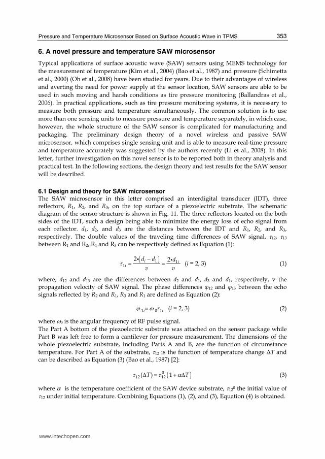
6.1 Design and theory for SAW microsensor The SAW microsensor in this letter comprised an interdigital transducer (IDT), three reflectors, R1, R2, and R3, on the top surface of a piezoelectric substrate. The schematic diagram of the sensor structure is shown in Fig. 11. The three reflectors located on the both sides of the IDT, such a design being able to minimize the energy loss of echo signal from each reflector. d1, d2, and d3 are the distances between the IDT and R1, R2, and R3, respectively. The double values of the traveling time differences of SAW signal, τ12, τ13 between R1 and R2, R1 and R3 can be respectively defined as Equation (1):
( )1 1
1
2 2i ii
d d d
v vτ −= =i i
(i = 2, 3) (1)
where, d12 and d13 are the differences between d2 and d1, d3 and d1, respectively, v the propagation velocity of SAW signal. The phase differences φ12 and φ13 between the echo signals reflected by R2 and R1, R3 and R1 are defined as Equation (2):
1 0 1i iϕ ω τ= (i = 2, 3) (2)
where ω0 is the angular frequency of RF pulse signal.
The Part A bottom of the piezoelectric substrate was attached on the sensor package while Part B was left free to form a cantilever for pressure measurement. The dimensions of the whole piezoelectric substrate, including Parts A and B, are the function of circumstance
temperature. For Part A of the substrate, τ12 is the function of temperature change ΔT and can be described as Equation (3) (Bao et al., 1987) [2]:
( )012 12( ) 1T Tτ τ αΔ = + Δ (3)
where α is the temperature coefficient of the SAW device substrate, τ120 the initial value of τ12 under initial temperature. Combining Equations (1), (2), and (3), Equation (4) is obtained.
www.intechopen.com

Acoustic Waves
354
Fig. 11. (a) Vertical view, and (b) profile view of schematic diagram of the sensor structure
12012 0
1
2
vT
dϕ ααωΔ = − (4)
Here, 012d is the initial value of d12 under initial temperature.
Since d13, which is the difference between d3 and d1 in Part B, is affected by both ΔT and
pressure, Equation (5) can be set up if the correlation of the effects of ΔT and pressure on τ13 is neglected (Li et al., 2008).
013 13( , ) 1P PT Tτ ε τ ε αΔ = + + Δ⎡ ⎤⎣ ⎦ (5)
Here, εP is the change of d13 caused by the pressure, τ130 the initial value of τ13 under initial temperature. Thus combining Equations (1), (2), (4), and (5), the phase shift being principally linear with applied pressure φP can be expressed as:
( )0 013 13 12 12 13 12P d d Wϕ ϕ ϕ ϕ ϕ= − = − (6)
where d130 is the initial value of d13 under initial temperature, W the weighted factor and equal to d130/d120.
6.2 Device and tests for SAW microsensor Y-Z cut LiNbO3 was used as the substrate material of the sensor. The dimensions of the sensor die are 18 mm long, 2 mm wide, and 0.5 mm thick, respectively. The IDT and the three reflectors R1, R2, and R3 were patterned onto the surface of the substrate using MEMS lift-off fabrication process. Fig. 12a is the schematic diagraph of a completely packaged
www.intechopen.com

Pressure and Temperature Microsensor Based on Surface Acoustic Wave in TPMS
355
sensor. Fig. 12b is the photograph of a real microsensor without the packaging header cap, showing more structural details inside the sensor. The package, which includes a sensitive membrane and a header cap together with the package base attaching part of the substrate bottom, sealed the piezoelectric substrate in a vacuum cavity. The sensitive end of the piezoelectric cantilever contacts the membrane with negligibly small pre-force. The pressure difference between the cavity and the outside pressure can cause the deformation of the cantilever end along the vertical direction through the sensing membrane. The SAW signal frequency for this sensor is 433 MHz, corresponding to a wavelength of 8 μm. The IDT aperture is 50 times wave length, and d1, d2, and d3 are 2400 μm, 4800 μm, and 7000 μm, respectively. Fig. 13 shows the different measured echo signals reflected from the correspondent reflectors of the sensor with an oscilloscope (DSA70604, Tektronix Co. Ltd., Pudong New Area, Shanghai, China). (Li et al., 2009) The SAW microsensor with complete packaging was tested in a sealed chamber, inside which the air pressure and temperature are controllable. The pressure was measured with the pressure meter embedded in an electro-pneumatic regulator (ITV2030, 1 kPa resolution, SMC, 1 Claymore Drive #08-05/06 Orchard Towers, Singapore). A Pt100 thermal resistance connected with a digital meter (0.1 °C resolution) was used to measure the inside temperature of the chamber. The pulse signals for testing the sensor were generated and received by a vector signal generator SMJ100A and a spectrum analyzer FSP, respectively. Both were made by Rohde-Schwarz, Mühldorfstraße 15, München, Germany. The test temperature and pressure values were recorded by a time interval of 10 s.
(a)
(b)
Fig. 12. (a) Schematic diagraph of a completely packaged sensor, and (b) photograph of a real microsensor without the packaging header cap
www.intechopen.com

Acoustic Waves
356
Fig. 13. Different measured echo signals from the reflectors
6.3 Results for SAW microsensor Fig. 14a shows the measured data of phase differences φ12, φ13 within the time range of 700 s, which are corresponding to the temperature and temperature effected pressure values, respectively. Using the measured φ12 by the SAW sensor and Equation (4), the calculated temperature values are compared with the direct measurement temperature data and shown in Fig. 14c. They match each other well although the calculated values have a higher temperature resolution than the direct measurement results, which was limited by the Pt 100 thermal resistance characteristics in the temperature range between 27.9 and 29.1 °C. The calculated pressure values eliminating the temperature variation effect using Equation (6) are shown in Fig. 14b, which agree the direct measured pressure data very well ranging from 0 to 150 kPa. (Li et al., 2009)
7. Conclusion
In this chapter, TPMS sensors are introduced, then a novel wireless passive SAW pressure and temperature microsensor with single sensing unit is reported. Its structural design, theoretical analysis, and test results are described. The calculated pressure and temperature values with this sensor measurement agree with the directly measured data very well.
8. References
Ballandras, S.; Lardat, R.; Penavaire, L. et al. (2006). Micro-machined, all quartz package, passive wireless SAW pressure and temperature sensor, IEEE Ultrasonics Symp., 1441-1444, 2006, Vancouver, Canada
Bao, X.; Burkhard, W.; Varadan, V. et al. (1987). SAW temperature sensor and remote reading system, Proc. IEEE Ultrasonics Symp., 583-585, 00905607, Denver, USA
Buff,W. ; Klett, S.; Rusko,M. et al. (1998). Passive Remote Sensing for Temperature and Pressure Using SAW Resonator Devices, IEEE Transactions on Ultrasonics, Ferroelectrics, and Frequency Control, Vol.45, No.5, 1388-1392, 08853010
www.intechopen.com

Pressure and Temperature Microsensor Based on Surface Acoustic Wave in TPMS
357
Fig. 14. (a) Measured phase differences with the SAW sensor Hollow circle and dashed line phase difference data of φ13
Hollow triangle and dashed line phase difference data of φ12
(b) Comparison between calculated pressure from sensor measurement and direct measured pressure Solid circle calculated pressure Thick solid line direct measured pressure (c) Comparison between calculated temperature from sensor measurement and direct measured temperature Solid triangle calculated temperature Thin solid line direct measured temperature
David, M. (2004). Safety Check: Wireless sensors eye tyre pressure, EDN Europe, No.9, 43-38 Kim, Y.; Chang, D. & Yoon, Y. (2004). Study on the optimization of a temperature sensor
based on SAW delay line, Korean Phys. Soc., Vol.45, No.5, 1366-1371, 0374-4884 Li, T.; Wu, Z.; Hu, H. et al. (2009). Pressure and temperature microsensor based on surface
acoustic wave, Electronics Letters, Vol.45, No.6, 337-338, 0013-5194 Li T.; Zheng L.; Hu H. (2008). A novel wireless passive SAW sensor based on the delay line
theory, Proc. 3rd IEEE International Conf. Nano/Micro Engineered and Molecular Systems, 440-443, 978-1-4244-1907-4, 2008, Sanya, China
Oh, J.; Choi, B.; Lee, S. (2008). SAW based passive sensor with passive signal conditioning using MEMS A/D converter, Sensors and Actuators A, Vol.141, No.2, 631-639, 0924-4247
www.intechopen.com

Acoustic Waves
358
Pohl, A.; Seifert, F. (1997). Wirelessly interrogable surface acoustic wave sensors for vehicular applications, IEEE Transactions on Instrumentation and Measurement, Vol.46, No.4, 1031-1037, 00189456
Reindl, L.; Ruppel, C. C.W.; Riek, K. et al. (1998) .A wireless AQP pressure sensor using chirped SAW delay line structures, IEEE Ultrasonics Symposium, Vol.1,355-358, 0780340957
Reindl, L.; Scholl, G.; Ostertag, T. et al. (1998). Theory and application of passive SAW radio transponders as sensors, IEEE Transactions on Ultrasonics, Ferroelectrics, and Frequency Control, Vol.45, No.5, 1281-1292, 0885-3010
Schimetta, G. ; Dollinger, F.; Scholl,G. et al. (2000). Wireless pressure and temperature measurement using a SAW hybrid sensor, IEEE Ultrasonics Symposium, Vol.1, 445-448, 0780363655
Schimetta, G.; Dollinger, F.; Weigel, R. (2000). A wireless pressure measurement system using a SAW hybrid sensor, IEEE Transactions on Microwave Theory and Techniques, Vol.48, No.12, 2730-2735, 0018-9480
Scholl, G.; Schmidt,F.; Ostertag, T. et al. (1998). Wireless passive SAW sensor system for industrial and domestic applications, l998 IEEE International Frequency Control Symposium, Vol.1, 595-601, 0780343735
Steidl, R.; Pohl,A.; Reindl, L. et al. (1998). SAW delay lines for wirelessly requestable conventional sensors, IEEE Ultrasonics Symposium, No.1, 351-354, 10510117
Wang, F.; Wang, Z.; Shan, G., et al. (2003). Study Progress and Prospect of Smart Tire. Tire Industry, Vol.23, No.1, 10-15
www.intechopen.com

Acoustic WavesEdited by Don Dissanayake
ISBN 978-953-307-111-4Hard cover, 434 pagesPublisher SciyoPublished online 28, September, 2010Published in print edition September, 2010
InTech EuropeUniversity Campus STeP Ri Slavka Krautzeka 83/A 51000 Rijeka, Croatia
InTech ChinaUnit 405, Office Block, Hotel Equatorial Shanghai No.65, Yan An Road (West), Shanghai, 200040, China
Phone: +86-21-62489820
SAW devices are widely used in multitude of device concepts mainly in MEMS and communication electronics.As such, SAW based micro sensors, actuators and communication electronic devices are well knownapplications of SAW technology. For example, SAW based passive micro sensors are capable of measuringphysical properties such as temperature, pressure, variation in chemical properties, and SAW basedcommunication devices perform a range of signal processing functions, such as delay lines, filters, resonators,pulse compressors, and convolvers. In recent decades, SAW based low-powered actuators and microfluidicdevices have significantly added a new dimension to SAW technology. This book consists of 20 excitingchapters composed by researchers and engineers active in the field of SAW technology, biomedical and otherrelated engineering disciplines. The topics range from basic SAW theory, materials and phenomena toadvanced applications such as sensors actuators, and communication systems. As such, in addition totheoretical analysis and numerical modelling such as Finite Element Modelling (FEM) and Finite DifferenceMethods (FDM) of SAW devices, SAW based actuators and micro motors, and SAW based micro sensors aresome of the exciting applications presented in this book. This collection of up-to-date information and researchoutcomes on SAW technology will be of great interest, not only to all those working in SAW based technology,but also to many more who stand to benefit from an insight into the rich opportunities that this technology hasto offer, especially to develop advanced, low-powered biomedical implants and passive communicationdevices.
How to referenceIn order to correctly reference this scholarly work, feel free to copy and paste the following:
Tianli Li, Hong Hu, Gang Xu, Kemin Zhu and Licun Fang (2010). Pressure and Temperature MicrosensorBased on Surface Acoustic Wave in TPMS, Acoustic Waves, Don Dissanayake (Ed.), ISBN: 978-953-307-111-4, InTech, Available from: http://www.intechopen.com/books/acoustic-waves/pressure-and-temperature-microsensor-based-on-surface-acoustic-wave-in-tpms
www.intechopen.com

Phone: +385 (51) 770 447 Fax: +385 (51) 686 166www.intechopen.com
Phone: +86-21-62489820 Fax: +86-21-62489821

© 2010 The Author(s). Licensee IntechOpen. This chapter is distributedunder the terms of the Creative Commons Attribution-NonCommercial-ShareAlike-3.0 License, which permits use, distribution and reproduction fornon-commercial purposes, provided the original is properly cited andderivative works building on this content are distributed under the samelicense.