Embed Size (px)
Citation preview
© MichałBanaś,PiotrAntoniak.,2014
Michał Banaś, PhD, Piotr Antoniak, PhD Wroclaw University of Technology, Wroclaw, Poland ([email protected])
PRESSURE CONTROL IN THE HYDRAULIC PUMP INLET
CHANNEL USING AN ELECTRONIC CONTROL UNIT
Банаш М., Антоняк П. Вроцлавский технологический университет, Вроцлав, Польша
РЕГУЛИРОВАНИЕ ДАВЛЕНИЯ В ЛИНИИ ВСАСЫВАНИЯ ГИДРАВЛИЧЕСКОГО
НАСОСА С ИСПОЛЬЗОВАНИЕМ ЭЛЕКТРОННОГО БЛОКА УПРАВЛЕНИЯ
The paper presents a system of inlet pressure control in a gear pump, used at a test stand during the research conducted by means of the PIV method and discusses important requirements of this method. An electronic control system with additional equipment has been applied in the control system. It controlled a proportional throttle flow control valve built-in parallel to the charger vane pump. The paper presents preliminary results and discusses the reasons of the control error. Steps to improve the control accuracy of the inlet pressure have been proposed. Keywords: PIV, test stand, gear pump, controller
Introduction Research on hydraulic units require a number of conditions related to the operation parameters of the hydraulic
system. Requirements vary not only because of the test object, but also need to take into account the methods used for it. It is important in many modern methods. An example might be keeping the pressure in the inlet and the outlet port of the hydraulic pump at the observation of the flow phenomena by the PIV (Particle Image Velocimetry) method [1]. Fluid Power Research Group from Wroclaw have been conducting research on the development of the inlet and outlet channels in the hydraulic pump [2]. The test’s program includes both operating of the pump at overpressure as well as at underpressure in the inlet port relative to the surroundings. Operation of the pump at high speed requires high flow suction, which is not possible without an additional fluid delivery system. On the test bench an additional charger pump with a constant displacement is used, which provides the required overpressure in the inlet channel at high speeds during the research. The use of this pump, however, generates overpressure at a low flow demand of the hydraulic fluid (low speeds) from the tested object. It became necessary to develop a pressure control system of the inlet port of the tested pump using the electronic control system.
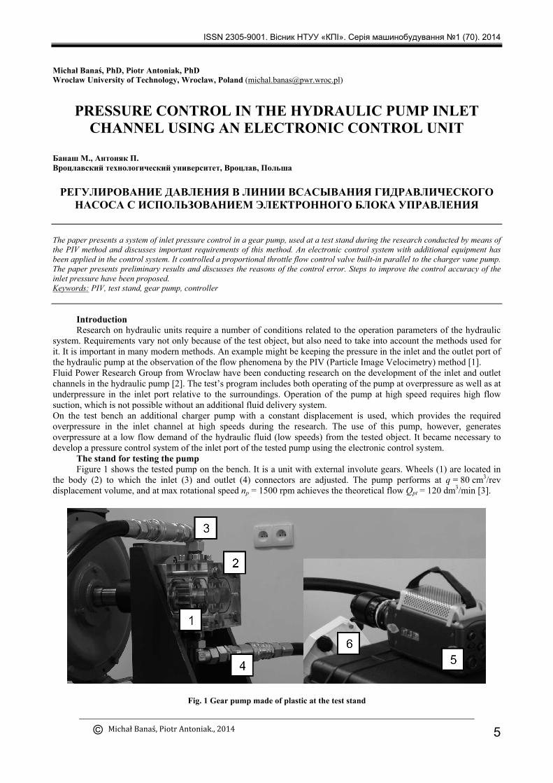
The stand for testing the pump Figure 1 shows the tested pump on the bench. It is a unit with external involute gears. Wheels (1) are located in
the body (2) to which the inlet (3) and outlet (4) connectors are adjusted. The pump performs at q = 80 cm3/rev displacement volume, and at max rotational speed np = 1500 rpm achieves the theoretical flow Qpt = 120 dm3/min [3].
Fig. 1 Gear pump made of plastic at the test stand
ISSN 2305-9001. Вісник НТУУ «КПІ». Серiя машинобудування №1 (70). 2014
5

Due to the research conducted with the use of PIV [4, 5], the housing (2) is made of plastic, which allows to observe flow effects within the pump. For these studies, high speed camera Phantom v7.3 (5) was used, which allowed to record at up to 6 000 fps with 800x600 resolution and up to 100 000 fps at reduced resolution [6]. Such a short exposure time requires proper lighting (6). The camera takes pictures in which movement of air bubbles generated during suction of the fluid through the pump can be observed. And on that basis, the distribution of the velocity field inside the inlet channel can be established.
The proportional throttle flow control valve TDA 016 EW 09 B2 produced by Parker [7] was used in the control system. The current operating range is 0-1050 mA, which corresponds to the maximum flow rate of 220 lpm at a pressure drop of 10 bar. The valve characteristic is non-linear with the opening point at 30% of the maximum current. At a lower current, the valve is closed. The role of the valve is to discharge the excess of the fluid to the tank in accordance with the desired setting so that the pressure in the inlet channel of the pump – hose (4) maintains a fixed value. There is a built-in tank (12) with the necessary equipment, including a filter and a cooler in the hydraulic power supply (8).
Fig. 2. Hydraulic system diagram of the test stand with the control system
A control system of the test stand consists of an electronic control system ECU (9) and a data acquisition system DAS (10). ECU is used to control the pressure in the inlet port of the test pump, and DAS records the research data. The pressure in the suction line (4) of the pump is measured by a pressure transducer (11) which converts the hydraulic signal p_in to voltage U_p, and then sends it to ECU and DAS. The proportional flow valve is controlled by the current signal i_fv from ECU.
Pressure control system Figure 3 shows a diagram of the gear pump's inlet pressure control system. Setpoint of the input pressure p_set is
compared with an actual value p_in and an error delpa_p is forwarded to ECU. In the ECU a PID controller was programmed, which determines the current value i_fv to control the proportional flow valve. In response to a change of the valve setting, the flow of the fluid discharged to the reservoir Q_fv changes, which affects the pump's inlet pressure p_in. The diagram includes examples of disturbances that occur in the hydraulic system, such as temperature change, and with it, the viscosity of the fluid and a change in the tested pump's speed.
The developed pressure control diagram was implemented using items illustrated schematically in figure 4. The basic element of the system is controller RC6 -9/20 by Bosch Rexroth, which works as ECU. The controller gets the voltage signal U_p from the pressure transducer additionally transformed within a converter to 0-5V. ECU controls the proportional flow valve with the current signal i_fv in a range 0-1.05A. Setting the required pressure p_set in the system is carried out on the control panel with 0-5V range output signal potentiometer.
ISSN 2305-9001. Вісник НТУУ «КПІ». Серiя машинобудування №1 (70). 2014
6

Fig. 3. Control system of the input pressure in the tested pump
A user can observe the selected parameters on the DI3 display, which communicates with the ECU using a CAN-Bus (Fig. 5). The display shows values of i_fv current, actual pressure p_in in the inlet channel as voltage U_p, the set pressure p_set as voltage U_set and the control error delta_p.
Fig. 4. Flow diagram of signals in the control system
For DAS measuring amplifier Spider8 by HMB connected to a PC was used. The DAS gets voltage signals U_p and U_set and the current signal of the proportional valve i_fv, as voltage U_fv of 0-5V.
Findings The results of the preliminary studies on the regulator have been shown in figure 6. The diagram presents
pressure changes in the inlet port of the gear pump p_in and the coil current of proportional valve i_fv. The tests were conducted at pressure p_set = 0.396 MPa, and the rotational speed of the tested pump n_p = 450 – 650 rev/min. The measurements frequency of DAS was f = 5 Hz.
The test results were obtained with the PID control amplification coefficients' values: Ki = 0.3, Kp = 0.4, Kd = 0. Because of the danger of the overshooting, which in the case of the tested pump can cause damage, such as excessive underpressure or overpressure in the inlet channel, the derivative term of the controller is disabled, taking the value of Kd = 0. The danger is associated with a too high pressure drop of input pressure p_in leading even to the cut off of the flow when the flow valve is fully open (Q_fv = max) or to an increase in the pressure and damage of the seal when the flow valve is closed (Q_fv = 0), and all the flow is directed into the inlet port. A limit of the maximum current to the coil to 900 mA was also implemented in the controller. Non-linearity of the actual characteristics of the valve was not corrected in the controller.
ISSN 2305-9001. Вісник НТУУ «КПІ». Серiя машинобудування №1 (70). 2014
7
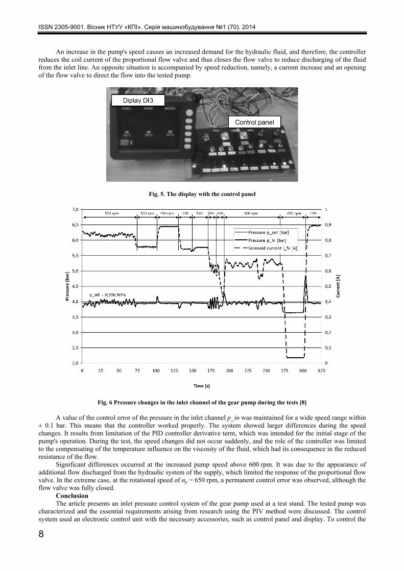
An increase in the pump's speed causes an increased demand for the hydraulic fluid, and therefore, the controller reduces the coil current of the proportional flow valve and thus closes the flow valve to reduce discharging of the fluid from the inlet line. An opposite situation is accompanied by speed reduction, namely, a current increase and an opening of the flow valve to direct the flow into the tested pump.
Fig. 5. The display with the control panel
Fig. 6 Pressure changes in the inlet channel of the gear pump during the tests [8]
A value of the control error of the pressure in the inlet channel p_in was maintained for a wide speed range within ± 0.1 bar. This means that the controller worked properly. The system showed larger differences during the speed changes. It results from limitation of the PID controller derivative term, which was intended for the initial stage of the pump's operation. During the test, the speed changes did not occur suddenly, and the role of the controller was limited to the compensating of the temperature influence on the viscosity of the fluid, which had its consequence in the reduced resistance of the flow.
Significant differences occurred at the increased pump speed above 600 rpm. It was due to the appearance of additional flow discharged from the hydraulic system of the supply, which limited the response of the proportional flow valve. In the extreme case, at the rotational speed of np = 650 rpm, a permanent control error was observed, although the flow valve was fully closed.
Conclusion The article presents an inlet pressure control system of the gear pump used at a test stand. The tested pump was
characterized and the essential requirements arising from research using the PIV method were discussed. The control system used an electronic control unit with the necessary accessories, such as control panel and display. To control the
ISSN 2305-9001. Вісник НТУУ «КПІ». Серiя машинобудування №1 (70). 2014
8

inlet pressure, a proportional flow valve built-in with a charger vane pump was used. The controller works properly and maintains a preset value of the input pressure. Speed change as well as temperature change associated with the time of the research are compensated by the controller. The overshooting, which was recorded during the change of the rotational speed, can be eliminated by changing of the controller gain coefficients' values.
Аннотация. В статье представлена система контроля давления на входе в шестеренный насос, используемый в испытательном стенде в ходе исследования, проведенного методом PIV и рассмотрены важные требования этого метода. В системе управления была применена электронная система управления с дополнительным оборудованием. Она управляет пропорциональным дросселирующим клапаном, установленным параллельно насосу для создания избыточного давления. В работе представлены предварительные результаты и обсуждаются причины ошибки управления. Были предложены шаги по улучшению точности управления давлением на входе. Ключевые слова: PIV, испытательный стенд, шестеренный насос, контроллер Анотація. У статті представлена система контролю тиску на вході в шестеренний насос, використовуваний у випробувальному стенді в ході дослідження, проведеного методом PIV і розглянуті важливі вимоги цього методу. У системі управління була застосована електронна система управління з додатковим обладнанням. Вона управляє пропорційним дроселюючим клапаном, встановленим паралельно насосу для створення надлишкового тиску. У роботі представлені попередні результати і обговорюються причини помилки управління. Були запропоновані кроки з поліпшення точності управління тиском на вході. Ключові слова: PIV, випробувальний стенд, шестеренний насос, контролер
References 1. Stryczek J.: Koła zębate maszyn hydraulicznych, Oficyna Wydawnicza Politechniki Wrocławskiej, Wrocław 2007, s. 30-144. 2. Stryczek J. et al., The se ries of units of the high displacement gear pumps WPZ, International Scientific- Technical
Conference Hydraulics And Pneumatics 2012, SIMP, May 16 – 18, 2012, Wroclaw (Poland). 3. Stryczek J., Antoniak P., Słodczyk D., Bednarczyk S., Banaś M.: Badanie i optymalizacja przepływów przez kanały i
szczeliny wewnętrzne w modelach pomp WPZ, Część I. Raport serii Sprawozdania nr S-001/11. Technical University of Wrocław, 2011, Wrocław.
4. Stryczek J. et al., Visualization research of the flow processes in the outlet chamber–outlet bridge–inlet chamber zone of the gear pumps, Archives of Civil and Mechanical Engineering (2014), http://dx.doi.org/10.1016/j.acme.2014.02.010.
5. Stryczek J., Antoniak P., Application of the particle image velocimetry (PIV) to the study on the flow in the internal channels and clearances of the hydraulic gear machines, International Science And Technology Forum, September 5 -7, 2012, Samara (Russia).
6. http://www.visionresearch.com/Products/High-Speed-Cameras/v73/ (2014.04.12). 7. http://www.parker.com/literature/Hydraulic%20Controls%20Europe/HY11-3500UK/PDF_2013/TDA%20UK.pdf
(2014.04.12). 8. Goleń W.: Projekt regulatora natężenia przepływu cieczy hydraulicznej. Thesis. Technical University of Wrocław, 2013,
Wrocław.
1. Stryczek J.: Koła zębate maszyn hydraulicznych (Gear wheels of hydraulic machinery), Oficyna Wydawnicza Politechniki
Wroclawskiej, Wroclaw 2007, p. 30-144. 2. Stryczek J. et al., The series of units of the high displacement gear pumps WPZ, International Scientific- Technical
Conference Hydraulics And Pneumatics 2012, SIMP, May 16 – 18, 2012, Wroclaw (Poland). 3. Stryczek J., Antoniak P., Słodczyk D., Bednarczyk S., Banaś M.: Badanie i optymalizacja przepływów przez kanały i
szczeliny wewnętrzne w modelach pomp WPZ, Część I. (Study and optimization of flow through the channels and slots internal pump models WPZ, Part I) Raport serii Sprawozdania nr S-001/11. Technical University of Wrocław, 2011, Wrocław.
4. Stryczek J. et al., Visualization research of the flow processes in the outlet chamber–outlet bridge–inlet chamber zone of the gear pumps, Archives of Civil and Mechanical Engineering (2014), http://dx.doi.org/10.1016/j.acme.2014.02.010.
5. Stryczek J., Antoniak P., Application of the particle image velocimetry (PIV) to the study on the flow in the internal channels and clearances of the hydraulic gear machines, International Science And Technology Forum, September 5 -7, 2012, Samara (Russia).
6. http://www.visionresearch.com/Products/High-Speed-Cameras/v73/ (2014.04.12). 7. http://www.parker.com/literature/Hydraulic%20Controls%20Europe/HY11-3500UK/PDF_2013/TDA%20UK.pdf
(2014.04.12). 8. Goleń W.: Projekt regulatora natężenia przepływu cieczy hydraulicznej. (Project of pressure-compensated flow control valve
of hydraulic fluid) Thesis. Technical University of Wrocław, 2013, Wrocław.
Подана до редакції 18.07.2014
ISSN 2305-9001. Вісник НТУУ «КПІ». Серiя машинобудування №1 (70). 2014
9


![Catalogue technique MG05 - Poclain Hydraulics€¦ · CleanStart system / Hydraulic starter POCLAIN HYDRAULICS ... [5000] P Inlet from pump G3 ... (Hirschmann) 4 P5 Hydraulic connections](https://img.pdfslide.net/doc/110x75/5b399b777f8b9a5a178e8fb3/catalogue-technique-mg05-poclain-cleanstart-system-hydraulic-starter-poclain.jpg)