Embed Size (px)
Citation preview
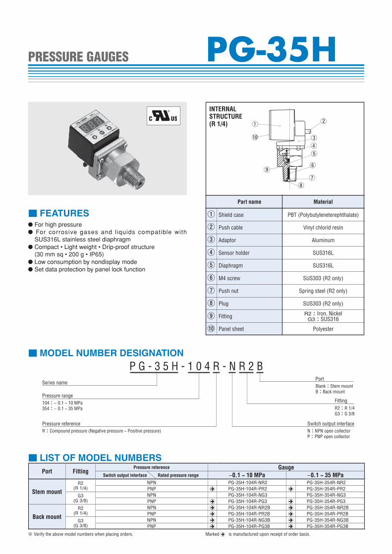
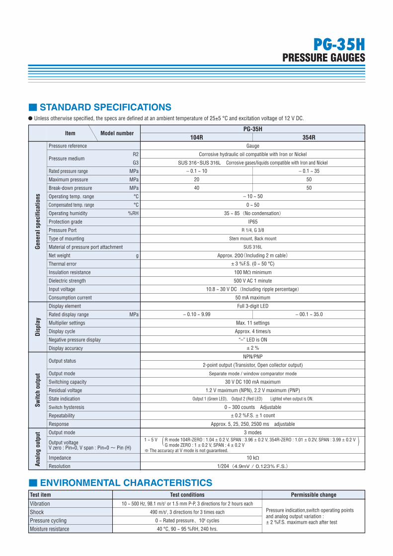
PG-35HPRESSURE GAUGES
● For high pressure● For corrosive gases and liquids compatible with
SUS316L stainless steel diaphragm● Compact • Light weight • Drip-proof structure
(30 mm sq • 200 g • IP65)● Low consumption by nondisplay mode● Set data protection by panel lock function
■ FEATURES
■ MODEL NUMBER DESIGNATION
P G - 3 5 H - 1 0 4 R - N R 2 BSeries name
Pressure range104:− 0.1 ~ 10 MPa354:− 0.1 ~ 35 MPa
Pressure referenceR:Compound pressure (Negative pressure ~ Positive pressure)
FittingR2:R 1/4G3:G 3/8
Switch output interface
Port
N:NPN open collectorP:PNP open collector
Blank:Stem mountB:Back mount
■ LIST OF MODEL NUMBERS
※ Verify the above model numbers when placing orders. Marked A is manufactured upon receipt of order basis.
Port FittingPressure reference Gauge
Switch output interface Rated pressure range −0.1 ~ 10 MPa −0.1 ~ 35 MPa
Stem mountR2
(R 1/4)NPN PG-35H-104R-NR2 PG-35H-354R-NR2PNP A PG-35H-104R-PR2 A PG-35H-354R-PR2
G3(G 3/8)
NPN PG-35H-104R-NG3 PG-35H-354R-NG3PNP A PG-35H-104R-PG3 A PG-35H-354R-PG3
Back mountR2
(R 1/4)NPN A PG-35H-104R-NR2B A PG-35H-354R-NR2BPNP A PG-35H-104R-PR2B A PG-35H-354R-PR2B
G3(G 3/8)
NPN A PG-35H-104R-NG3B A PG-35H-354R-NG3BPNP A PG-35H-104R-PG3B A PG-35H-354R-PG3B
①②③④⑤⑥⑦⑧⑨⑩
Part name Material
Adaptor
Push cable
Sensor holder
Diaphragm
M4 screw
Push nut
Plug
Fitting
Shield case
12
3
6
7
8
9
5
4
!0
PBT (Polybutyleneterephthalate)
Vinyl chlorid resin
Aluminum
SUS316L
SUS316L
SUS303 (R2 only)
Spring steel (R2 only)
SUS303 (R2 only)
R2:Iron, NickelG3:SUS316
Panel sheet Polyester
INTERNAL STRUCTURE(R 1/4)
Permissible change
PG-35H
PG-35HPRESSURE GAUGES
Gene
ral s
peci
ficat
ions
Disp
lay
Switc
h ou
tput
Anal
og o
utpu
t
Item Model number 104R 354R
■ STANDARD SPECIFICATIONS
Pressure reference Gauge
Corrosive hydraulic oil compatible with Iron or Nickel
SUS 316・SUS 316L Corrosive gases/liquids compatible with Iron and Nickel
− 0.1 ~ 10 − 0.1 ~ 35
20 50
40 50
− 10 ~ 50
0 ~ 50
35 ~ 85(No condensation)
IP65
R 1/4, G 3/8
Stem mount, Back mount
SUS 316L
Approx. 200(Including 2 m cable)
± 3 %F.S. (0 ~ 50 °C)
100 MΩ minimum
500 V AC 1 minute
10.8 ~ 30 V DC(Including ripple percentage)
50 mA maximum
Full 3-digit LED
− 0.10 ~ 9.99 − 00.1 ~ 35.0
Max. 11 settings
Approx. 4 times/s
“–” LED is ON
± 2 %
2-point output (Transistor, Open collector output)
Separate mode / window comparator mode
30 V DC 100 mA maximum
1.2 V maximum (NPN), 2.2 V maximum (PNP)
Output 1 (Green LED), Output 2 (Red LED) Lighted when output is ON.
0 ~ 300 counts Adjustable
± 0.2 %F.S. ± 1 count
Approx. 5, 25, 250, 2500 ms adjustable
3 modes
10 kΩ
1/204(4.9mV / 0.123% F.S.)
1 ~ 5 V R mode 104R-ZERO : 1.04 ± 0.2 V, SPAN : 3.96 ± 0.2 V, 354R-ZERO : 1.01 ± 0.2V, SPAN : 3.99 ± 0.2 V G mode ZERO : 1 ± 0.2 V, SPAN : 4 ± 0.2 V※ The accuracy at V mode is not guaranteed.
NPN/PNP
Pressure medium
Rated pressure range
Maximum pressure MPa
MPa
R2
G3
Break-down pressure
Operating temp. range
Compensated temp. range
Operating humidity
Protection grade
Pressure Port
Type of mounting
Material of pressure port attachment
Net weight g
Thermal error
Insulation resistance
Dielectric strength
Input voltage
Consumption current
Display element
Rated display range MPa
Multiplier settings
Display cycle
Negative pressure display
Display accuracy
Output status
Output mode
Switching capacity
Residual voltage
State indication
Switch hysteresis
Repeatability
Response
Output mode
Output voltageV zero : Pin=0, V span : Pin=0 〜 Pin (H)
Impedance
Resolution
( )
MPa
°C
°C
%RH
● Unless otherwise specified, the specs are defined at an ambient temperature of 25±5 °C and excitation voltage of 12 V DC.
■ ENVIRONMENTAL CHARACTERISTICSTest item Test conditions
Pressure indication,switch operating points and analog output variation :± 2 %F.S. maximum each after test
Vibration 10 ~ 500 Hz, 98.1 m/s2 or 1.5 mm P-P, 3 directions for 2 hours each
490 m/s2, 3 directions for 3 times each
0 ~ Rated pressure、106 cycles
40 °C, 90 ~ 95 %RH, 240 hrs.
ShockPressure cyclingMoisture resistance
Port
N:NPN open collectorP:PNP open collector
Blank:Stem mountB:Back mount
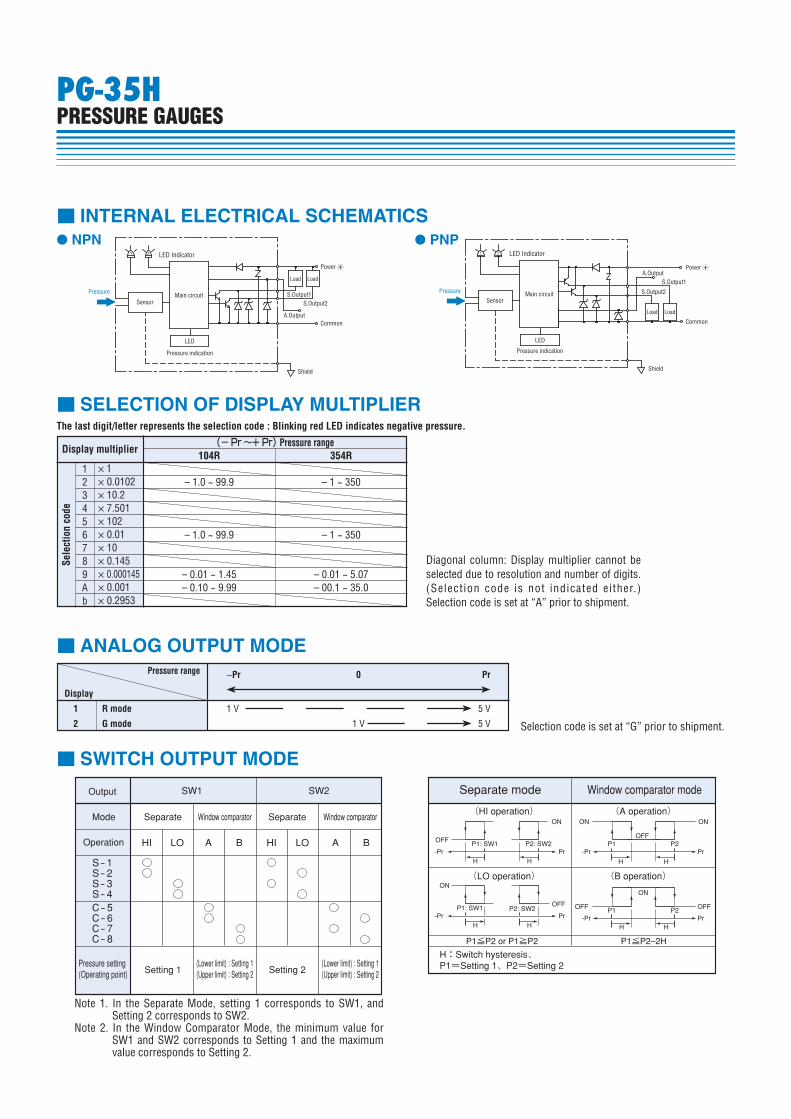
Display multiplier
Sele
ctio
n co
de
1 × 1× 0.0102× 10.2× 7.501× 102× 0.01× 10× 0.145× 0.000145× 0.001× 0.2953
23456789Ab
(− Pr 〜+ Pr) Pressure range
The last digit/letter represents the selection code : Blinking red LED indicates negative pressure.
104R 354R
– 1.0 ~ 99.9 – 1 ~ 350
– 1.0 ~ 99.9 – 1 ~ 350
– 0.01 ~ 1.45 – 0.01 ~ 5.07 – 0.10 ~ 9.99 – 00.1 ~ 35.0
1 R mode
2 G mode
Display
A.Output
Shield
Load
S.Output1Main circuit
Power B
Sensor
Common
S.Output2
Load
21
LED
Pressure
LED Indicator
圧力表示 Pressure indication
A.Output
Shield
Sensor
S.Output1
S.Output2
Load
Pressure
Power B
1 2
LED
Common
Load
Main circuit
LED Indicator
圧力表示 Pressure indication
■ INTERNAL ELECTRICAL SCHEMATICS
■ SELECTION OF DISPLAY MULTIPLIER
■ ANALOG OUTPUT MODE
■ SWITCH OUTPUT MODE
SW1 SW2
S-1S-2S-3S-4C-5C-6C-7C-8
HI LO A B HI LO A B P1: SW1 P2: SW2 P1 P2
P1 P2
OFF
ON ON
ON
ON
-Pr
OFF OFF
OFF
Pr -Pr Pr
-Pr Pr
H H
P1: SW1 P2: SW2 OFF
ON
-Pr PrH H
H H
H H
P1≦P2 or P1≧P2 P1≦P2–2H
Output
Mode Separate Window comparator Separate(HI operation)
(LO operation)
H:Switch hysteresis、P1=Setting 1、P2=Setting 2
(A operation)
(B operation)
Window comparator
Pressure setting(Operating point) Setting 1
(Lower limit) : Setting 1(Upper limit) : Setting 2
(Lower limit) : Setting 1(Upper limit) : Setting 2Setting 2
Separate mode Window comparator mode
Operation
Diagonal column: Display multiplier cannot be selected due to resolution and number of digits. (Select ion code is not indicated either.) Selection code is set at “A” prior to shipment.
Selection code is set at “G” prior to shipment.
Note 1. In the Separate Mode, setting 1 corresponds to SW1, and Setting 2 corresponds to SW2.
Note 2. In the Window Comparator Mode, the minimum value for SW1 and SW2 corresponds to Setting 1 and the maximum value corresponds to Setting 2.
Pressure range
1 V 5 V
1 V 5 V
−Pr 0 Pr
● NPN ● PNP
PG-35HPRESSURE GAUGES
PG-35HPRESSURE GAUGES
■ OUTLINE DIMENSIONS Unless otherwise specified tolerance : ± 0.5 (Unit: mm)
● Fitting R2 (R 1/4)
● Fitting G3 (G 3/8)
Pressure port φ 4
( )
R 1/4(PT 1/4)
φ 4
(73.
2)
30
30
37
10.5
16 Iron, Ni-plated 7.75
16
Depth 52 – M4
L = 2000 ± 100AWG26
5 wire shield cable
COPAL ELECTRONICS
G 3/8(PF 3/8)SUS316
( )φ 4
φ 5
(79.
2)
30
30
37
10.5
16
7.7
5
3
16
Depth 52 – M4
L = 2000 ± 100AWG26
5 wire shield cable
COPAL ELECTRONICS
Wire colorBrownGrayBlackWhiteBlueShield
ConnectionPower B
Analog outputSwitch output 1Switch output 2CommonFitting
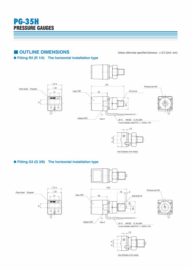
■ OUTLINE DIMENSIONS Unless otherwise specified tolerance : ± 0.5 (Unit: mm)
● Fitting R2 (R 1/4) The horizontal installation type
● Fitting G3 (G 3/8) The horizontal installation type
36
88
5.5
(72)
26 0 -0
.3
R1/4:Fe,Ni
5-core shielded cable:PVC L = 2000 ± 100 (Φ4) AWG26 UL No.2844
View A(Details of Air intake)
Pressure port Φ4
Adapter:ADC View A
Case:PBT
MPa
10
21
□30
□31.4
Panel sheet Polyester
MPa
View A
View A(Details of Air intake)
10
21
□30
□31.4
36
88
5.5
Adapter:ADC
Case:PBTPanel sheet Polyester
G3/8:SUS316
(78)
26 0 -0
.3
Pressure port Φ2 18 3
Φ5
5-core shielded cable:PVC L = 2000 ± 100 (Φ4) AWG26 UL No.2844
PG-35HPRESSURE GAUGES
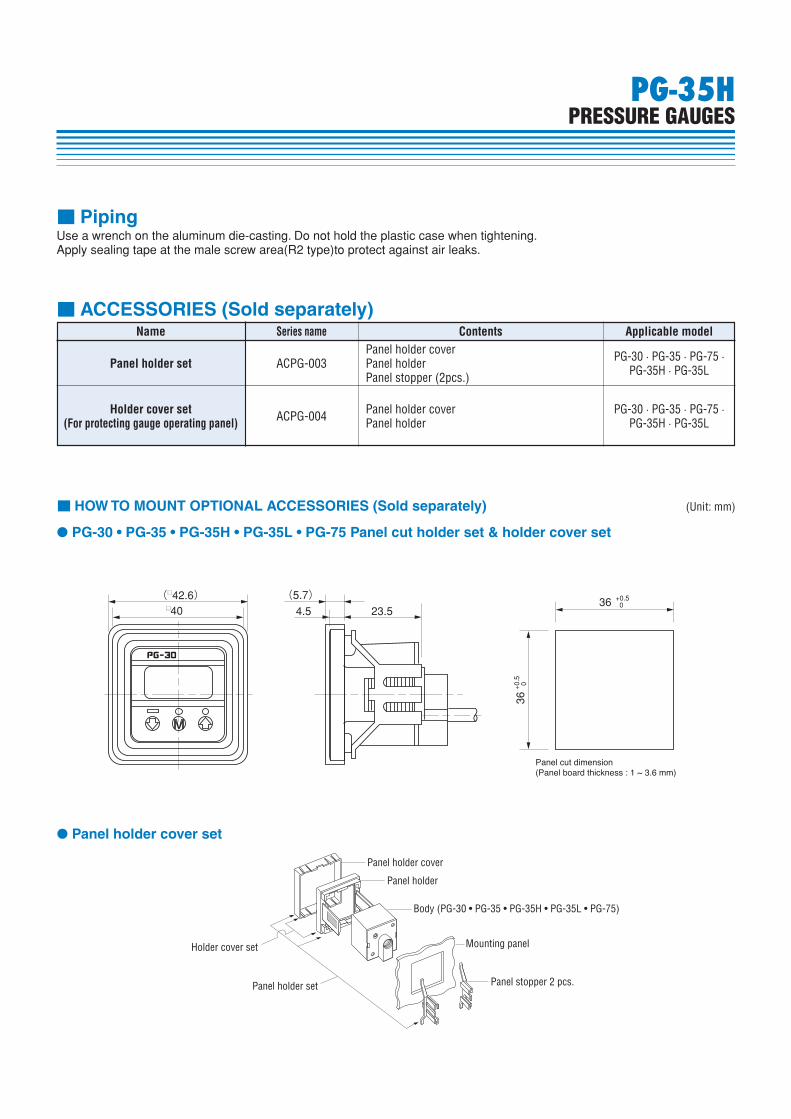
Use a wrench on the aluminum die-casting. Do not hold the plastic case when tightening.Apply sealing tape at the male screw area(R2 type)to protect against air leaks.
■ Piping
PG-35HPRESSURE GAUGES
(□42.6) (5.7)4.5 23.5□40
36 +0.5 0
36+0
.5 0
Panel cut dimension(Panel board thickness : 1 ~ 3.6 mm)
● PG-30 • PG-35 • PG-35H • PG-35L • PG-75 Panel cut holder set & holder cover set
Panel holder cover
Panel holder
Body (PG-30 • PG-35 • PG-35H • PG-35L • PG-75)
Mounting panel
Panel stopper 2 pcs.
Holder cover set
Panel holder set
● Panel holder cover set
■ HOW TO MOUNT OPTIONAL ACCESSORIES (Sold separately) (Unit: mm)
Applicable model
■ ACCESSORIES (Sold separately)Name Series name Contents
Panel holder coverPanel holderPanel stopper (2pcs.)
PG-30 · PG-35 · PG-75 ·PG-35H · PG-35L
PG-30 · PG-35 · PG-75 ·PG-35H · PG-35L
Panel holder coverPanel holder
ACPG-003
ACPG-004
Panel holder set
Holder cover set(For protecting gauge operating panel)