Embed Size (px)
Citation preview
1/171Siemens FI 01 · 2016 US Edition
Pressure MeasurementTransmitters for applications with advanced requirements (Advanced)
SITRANS P DS III for level1
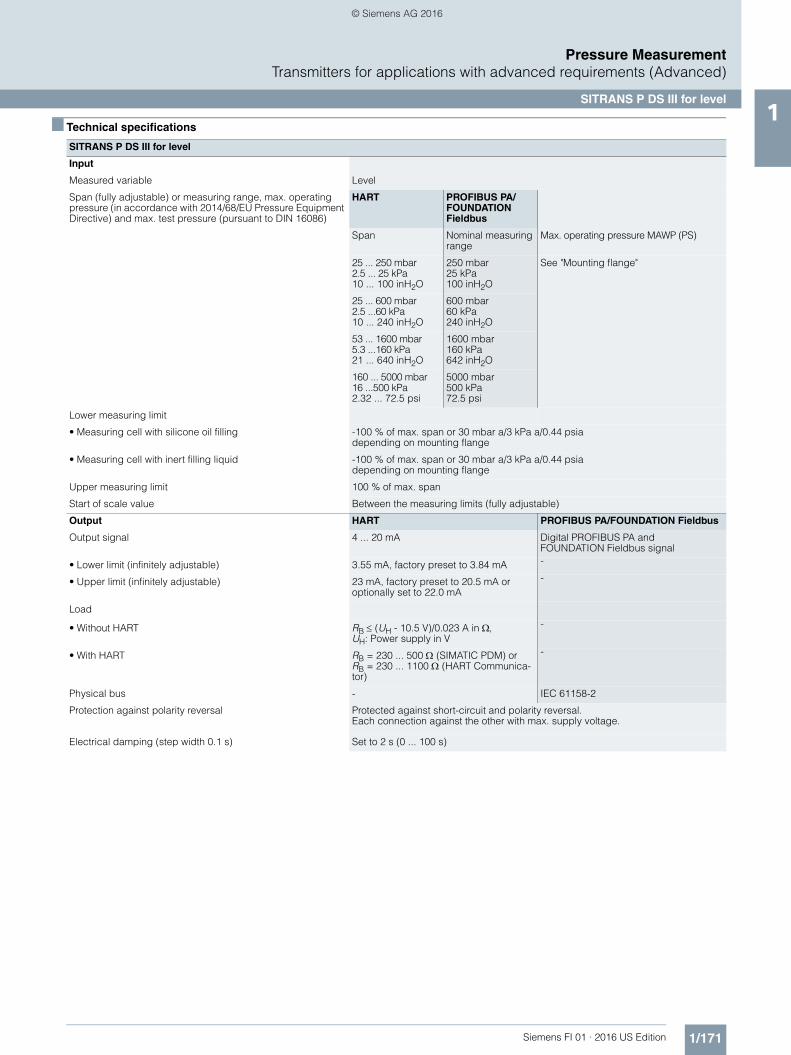
■ Technical specifications
SITRANS P DS III for level
Input
Measured variable Level
Span (fully adjustable) or measuring range, max. operating pressure (in accordance with 2014/68/EU Pressure Equipment Directive) and max. test pressure (pursuant to DIN 16086)
HART PROFIBUS PA/ FOUNDATION Fieldbus
Span Nominal measuring range
Max. operating pressure MAWP (PS)
25 ... 250 mbar2.5 ... 25 kPa10 ... 100 inH2O
250 mbar25 kPa100 inH2O
See "Mounting flange"
25 ... 600 mbar2.5 ...60 kPa10 ... 240 inH2O
600 mbar60 kPa240 inH2O
53 ... 1600 mbar5.3 ...160 kPa21 ... 640 inH2O
1600 mbar160 kPa642 inH2O
160 ... 5000 mbar16 ...500 kPa2.32 ... 72.5 psi
5000 mbar500 kPa72.5 psi
Lower measuring limit
• Measuring cell with silicone oil filling -100 % of max. span or 30 mbar a/3 kPa a/0.44 psiadepending on mounting flange
• Measuring cell with inert filling liquid -100 % of max. span or 30 mbar a/3 kPa a/0.44 psia depending on mounting flange
Upper measuring limit 100 % of max. span
Start of scale value Between the measuring limits (fully adjustable)
Output HART PROFIBUS PA/FOUNDATION Fieldbus
Output signal 4 ... 20 mA Digital PROFIBUS PA and FOUNDATION Fieldbus signal
• Lower limit (infinitely adjustable) 3.55 mA, factory preset to 3.84 mA -
• Upper limit (infinitely adjustable) 23 mA, factory preset to 20.5 mA or optionally set to 22.0 mA
-
Load
• Without HART RB (UH - 10.5 V)/0.023 A in ,UH: Power supply in V
-
• With HART RB = 230 ... 500 (SIMATIC PDM) orRB = 230 ... 1100 (HART Communica-tor)
-
Physical bus - IEC 61158-2
Protection against polarity reversal Protected against short-circuit and polarity reversal. Each connection against the other with max. supply voltage.
Electrical damping (step width 0.1 s) Set to 2 s (0 ... 100 s)
FI01_2016_us_kap01.book Seite 171 Montag, 27. Juni 2016 2:32 14
© Siemens AG 2016
1/172 Siemens FI 01 · 2016 US Edition
Pressure MeasurementTransmitters for applications with advanced requirements (Advanced)
SITRANS P DS III for level1
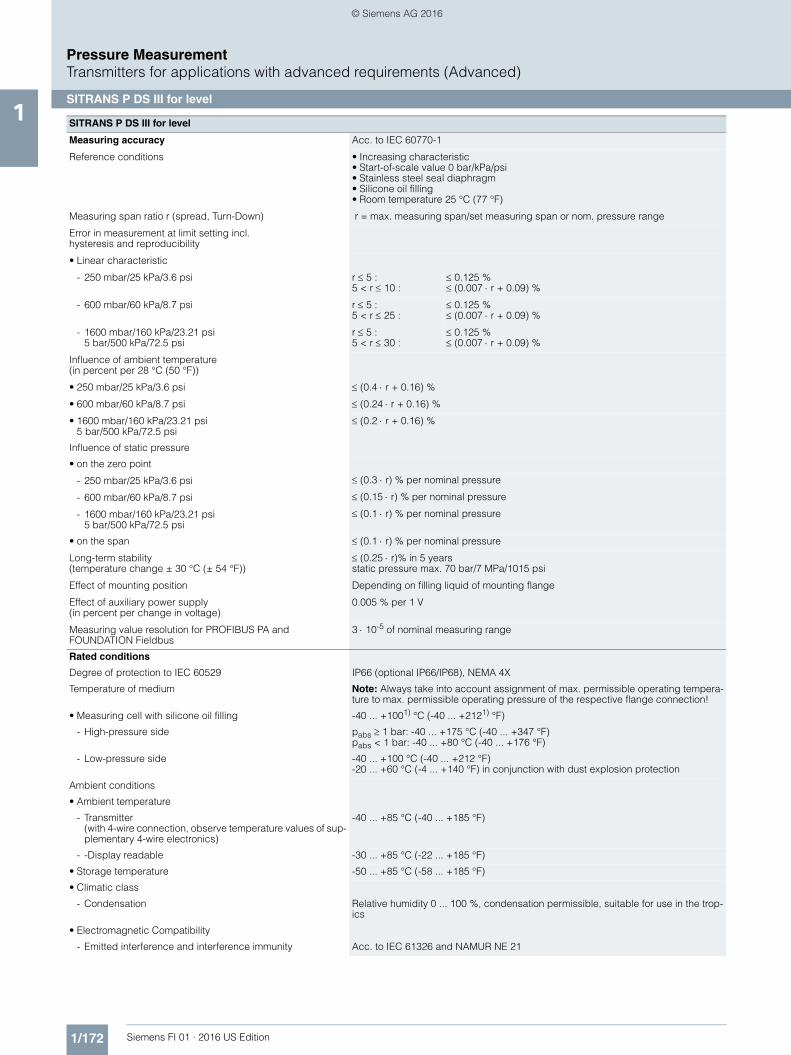
SITRANS P DS III for level
Measuring accuracy Acc. to IEC 60770-1
Reference conditions • Increasing characteristic• Start-of-scale value 0 bar/kPa/psi• Stainless steel seal diaphragm• Silicone oil filling• Room temperature 25 °C (77 °F)
Measuring span ratio r (spread, Turn-Down) r = max. measuring span/set measuring span or nom. pressure range
Error in measurement at limit setting incl. hysteresis and reproducibility
• Linear characteristic
- 250 mbar/25 kPa/3.6 psi r 5 :5 < r 10 :
0.125 % (0.007 r + 0.09) %
- 600 mbar/60 kPa/8.7 psi r 5 :5 < r 25 :
0.125 % (0.007 r + 0.09) %
- 1600 mbar/160 kPa/23.21 psi5 bar/500 kPa/72.5 psi
r 5 :5 < r 30 :
0.125 % (0.007 r + 0.09) %
Influence of ambient temperature (in percent per 28 °C (50 °F))
• 250 mbar/25 kPa/3.6 psi (0.4 r + 0.16) %
• 600 mbar/60 kPa/8.7 psi (0.24 r + 0.16) %
• 1600 mbar/160 kPa/23.21 psi5 bar/500 kPa/72.5 psi
(0.2 r + 0.16) %
Influence of static pressure
• on the zero point
- 250 mbar/25 kPa/3.6 psi (0.3 r) % per nominal pressure
- 600 mbar/60 kPa/8.7 psi (0.15 r) % per nominal pressure
- 1600 mbar/160 kPa/23.21 psi5 bar/500 kPa/72.5 psi
(0.1 r) % per nominal pressure
• on the span (0.1 r) % per nominal pressure
Long-term stability (temperature change ± 30 °C (± 54 °F))
(0.25 r)% in 5 years static pressure max. 70 bar/7 MPa/1015 psi
Effect of mounting position Depending on filling liquid of mounting flange
Effect of auxiliary power supply (in percent per change in voltage)
0.005 % per 1 V
Measuring value resolution for PROFIBUS PA and FOUNDATION Fieldbus
3 10-5 of nominal measuring range
Rated conditions
Degree of protection to IEC 60529 IP66 (optional IP66/IP68), NEMA 4X
Temperature of medium Note: Always take into account assignment of max. permissible operating tempera-ture to max. permissible operating pressure of the respective flange connection!
• Measuring cell with silicone oil filling -40 ... +1001) °C (-40 ... +2121) °F)
- High-pressure side pabs 1 bar: -40 ... +175 °C (-40 ... +347 °F)pabs < 1 bar: -40 ... +80 °C (-40 ... +176 °F)
- Low-pressure side -40 ... +100 °C (-40 ... +212 °F)-20 ... +60 °C (-4 ... +140 °F) in conjunction with dust explosion protection
Ambient conditions
• Ambient temperature
- Transmitter (with 4-wire connection, observe temperature values of sup-plementary 4-wire electronics)
-40 ... +85 °C (-40 ... +185 °F)
- -Display readable -30 ... +85 °C (-22 ... +185 °F)
• Storage temperature -50 ... +85 °C (-58 ... +185 °F)
• Climatic class
- Condensation Relative humidity 0 ... 100 %, condensation permissible, suitable for use in the trop-ics
• Electromagnetic Compatibility
- Emitted interference and interference immunity Acc. to IEC 61326 and NAMUR NE 21
FI01_2016_us_kap01.book Seite 172 Montag, 27. Juni 2016 2:32 14
© Siemens AG 2016

1/173Siemens FI 01 · 2016 US Edition
Pressure MeasurementTransmitters for applications with advanced requirements (Advanced)
SITRANS P DS III for level1
SITRANS P DS III for level
Design
Weight (without options)
• To EN (pressure transmitter with mounting flange, without tube)
11 ... 13 kg ( 24.2 ... 28.7 (lb)
• To ASME (pressure transmitter with mounting flange, without tube)
11 ... 18 kg ( 24.2 ... 39.7 lb)
Enclosure material Low-copper die-cast aluminum, GD-AlSi12 or stainless steel precision casting, mat. no. 1.4408
Wetted parts materials
High-pressure side
• Seal diaphragm of mounting flange • Stainless steel, W.-Nr. 1.4404/316L- coated with PFA- coated with PTFE - coated with ECTFE - gold plated
• Monel 400, mat. no. 2.4360• Hastelloy C276, mat. no 2.4619• Hastelloy C4, mat. no. 2.4602• Hastelloy C22, mat. no. 2.4602• Tantalum• Titanium, mat. no. 3.7035• Nickel 201• Duplex 2205, mat. no. 1.4462
Measuring cell filling Silicone oil
Process connection
• High-pressure side Flange to EN and ASME
• Low-pressure side Female thread ¼-18 NPT and flange connection with mounting thread M10 to DIN 19213 or 7/16-20 UNF to EN 61518
Power supply UH HART PROFIBUS PA/FOUNDATION Fieldbus
Terminal voltage on transmitter 10.5 ... 45 V DC10.5 ... 30 V DC in intrinsically-safe mode
-
Power supply Supplied through bus
Separate 24 V power supply necessary - No
Bus voltage
• Not Ex - 9 ... 32 V
• With intrinsically-safe operation - 9 ... 24 V
Current consumption
• Basic current (max.) - 12.5 mA
• Start-up current basic current - Yes
• Max. current in event of fault - 15.5 mA
Fault disconnection electronics (FDE) available - Yes
FI01_2016_us_kap01.book Seite 173 Montag, 27. Juni 2016 2:32 14
© Siemens AG 2016
1/174 Siemens FI 01 · 2016 US Edition
Pressure MeasurementTransmitters for applications with advanced requirements (Advanced)
SITRANS P DS III for level1
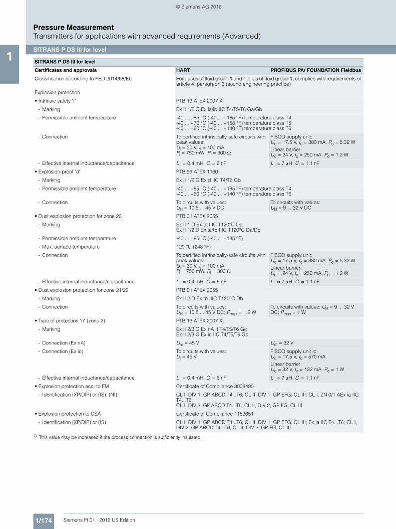
1) This value may be increased if the process connection is sufficiently insulated.
SITRANS P DS III for level
Certificates and approvals HART PROFIBUS PA/ FOUNDATION Fieldbus
Classification according to PED 2014/68/EU For gases of fluid group 1 and liquids of fluid group 1; complies with requirements of article 4, paragraph 3 (sound engineering practice)
Explosion protection
• Intrinsic safety "i" PTB 13 ATEX 2007 X
- Marking Ex II 1/2 G Ex ia/ib IIC T4/T5/T6 Ga/Gb
- Permissible ambient temperature -40 ... +85 °C (-40 ... +185 °F) temperature class T4;-40 ... +70 °C (-40 ... +158 °F) temperature class T5;-40 ... +60 °C (-40 ... +140 °F) temperature class T6
- Connection To certified intrinsically-safe circuits with peak values: Ui = 30 V, Ii = 100 mA, Pi = 750 mW; Ri = 300
FISCO supply unit: Uo = 17.5 V, Io = 380 mA, Po = 5.32 WLinear barrier: Uo = 24 V, Io = 250 mA, Po = 1.2 W
- Effective internal inductance/capacitance L i = 0.4 mH, Ci = 6 nF L i = 7 H, Ci = 1.1 nF
• Explosion-proof "d" PTB 99 ATEX 1160
- Marking Ex II 1/2 G Ex d IIC T4/T6 Gb
- Permissible ambient temperature -40 ... +85 °C (-40 ... +185 °F) temperature class T4;-40 ... +60 °C (-40 ... +140 °F) temperature class T6
- Connection To circuits with values: UH = 10.5 ... 45 V DC
To circuits with values: UH = 9 ... 32 V DC
• Dust explosion protection for zone 20 PTB 01 ATEX 2055
- Marking Ex II 1 D Ex ta IIIC T120°C DaEx II 1/2 D Ex ta/tb IIIC T120°C Da/Db
- Permissible ambient temperature -40 ... +85 °C (-40 ... +185 °F)
- Max. surface temperature 120 °C (248 °F)
- Connection To certified intrinsically-safe circuits with peak values: Ui = 30 V, Ii = 100 mA, Pi = 750 mW, Ri = 300
FISCO supply unit: Uo = 17.5 V, Io = 380 mA, Po = 5.32 WLinear barrier: Uo = 24 V, Io = 250 mA, Po = 1.2 W
- Effective internal inductance/capacitance L i = 0.4 mH, Ci = 6 nF L i = 7 H, Ci = 1.1 nF
• Dust explosion protection for zone 21/22 PTB 01 ATEX 2055
- Marking Ex II 2 D Ex tb IIIC T120°C Db
- Connection To circuits with values: UH = 10.5 ... 45 V DC; Pmax = 1.2 W
To circuits with values: UH = 9 ... 32 V DC; Pmax = 1 W
• Type of protection "n" (zone 2) PTB 13 ATEX 2007 X
- Marking Ex II 2/3 G Ex nA II T4/T5/T6 GcEx II 2/3 G Ex ic IIC T4/T5/T6 Gc
- Connection (Ex nA) Um = 45 V Um = 32 V
- Connection (Ex ic) To circuits with values: Ui = 45 V
FISCO supply unit ic: Uo = 17.5 V, Io = 570 mALinear barrier: Uo = 32 V, Io = 132 mA, Po = 1 W
- Effective internal inductance/capacitance L i = 0.4 mH, Ci = 6 nF L i = 7 H, Ci = 1.1 nF
• Explosion protection acc. to FM Certificate of Compliance 3008490
- Identification (XP/DIP) or (IS); (NI) CL I, DIV 1, GP ABCD T4...T6; CL II, DIV 1, GP EFG; CL III; CL I, ZN 0/1 AEx ia IIC T4...T6; CL I, DIV 2, GP ABCD T4...T6; CL II, DIV 2, GP FG; CL III
• Explosion protection to CSA Certificate of Compliance 1153651
- Identification (XP/DIP) or (IS) CL I, DIV 1, GP ABCD T4...T6; CL II, DIV 1, GP EFG; CL III; Ex ia IIC T4...T6; CL I, DIV 2, GP ABCD T4...T6; CL II, DIV 2, GP FG; CL III
FI01_2016_us_kap01.book Seite 174 Montag, 27. Juni 2016 2:32 14
© Siemens AG 2016
1/175Siemens FI 01 · 2016 US Edition
Pressure MeasurementTransmitters for applications with advanced requirements (Advanced)
SITRANS P DS III for level1
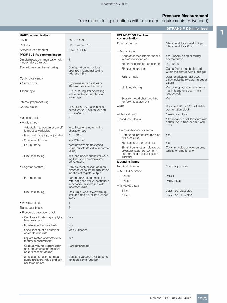
HART communication
HART 230 ... 1100
Protocol HART Version 5.x
Software for computer SIMATIC PDM
PROFIBUS PA communication
Simultaneous communication with master class 2 (max.)
4
The address can be set using Configuration tool or local operation (standard setting address 126)
Cyclic data usage
• Output byte 5 (one measured value) or10 (two measured values)
• Input byte 0, 1, or 2 (register operating mode and reset function for metering)
Internal preprocessing
Device profile PROFIBUS PA Profile for Pro-cess Control Devices Version 3.0, class B
Function blocks 2
• Analog input
- Adaptation to customer-specif-ic process variables
Yes, linearly rising or falling characteristic
- Electrical damping, adjustable 0 ... 100 s
- Simulation function Input/Output
- Failure mode parameterizable (last good value, substitute value, incorrect value)
- Limit monitoring Yes, one upper and lower warn-ing limit and one alarm limit respectively
• Register (totalizer) Can be reset, preset, optional direction of counting, simulation function of register output
- Failure mode parameterizable (summation with last good value, continuous summation, summation with incorrect value)
- Limit monitoring One upper and lower warning limit and one alarm limit respec-tively
• Physical block 1
Transducer blocks 2
• Pressure transducer block
- Can be calibrated by applying two pressures
Yes
- Monitoring of sensor limits Yes
- Specification of a container characteristic with
Max. 30 nodes
- Square-rooted characteristic for flow measurement
Yes
- Gradual volume suppression and implementation point of square-root extraction
Parameterizable
- Simulation function for mea-sured pressure value and sen-sor temperature
Constant value or over parame-terizable ramp function
FOUNDATION Fieldbus communication
Function blocks 3 function blocks analog input, 1 function block PID
• Analog input
- Adaptation to customer-specif-ic process variables
Yes, linearly rising or falling characteristic
- Electrical damping, adjustable 0 ... 100 s
- Simulation function Output/input (can be locked within the device with a bridge)
- Failure mode parameterizable (last good value, substitute value, incorrect value)
- Limit monitoring Yes, one upper and lower warn-ing limit and one alarm limit respectively
- Square-rooted characteristic for flow measurement
Yes
• PID Standard FOUNDATION Field-bus function block
• Physical block 1 resource block
Transducer blocks 1 transducer block Pressure with calibration, 1 transducer block LCD
• Pressure transducer block
- Can be calibrated by applying two pressures
Yes
- Monitoring of sensor limits Yes
- Simulation function: Measured pressure value, sensor tem-perature and electronics tem-perature
Constant value or over parame-terizable ramp function
Mounting flange
Nominal diameter Nominal pressure
• Acc. to EN 1092-1
- DN 80 PN 40
- DN100 PN16, PN40
• To ASME B16.5
- 3 inch class 150, class 300
- 4 inch class 150, class 300
FI01_2016_us_kap01.book Seite 175 Montag, 27. Juni 2016 2:32 14
© Siemens AG 2016
1/176 Siemens FI 01 · 2016 US Edition
Pressure MeasurementTransmitters for applications with advanced requirements (Advanced)
SITRANS P DS III for level1
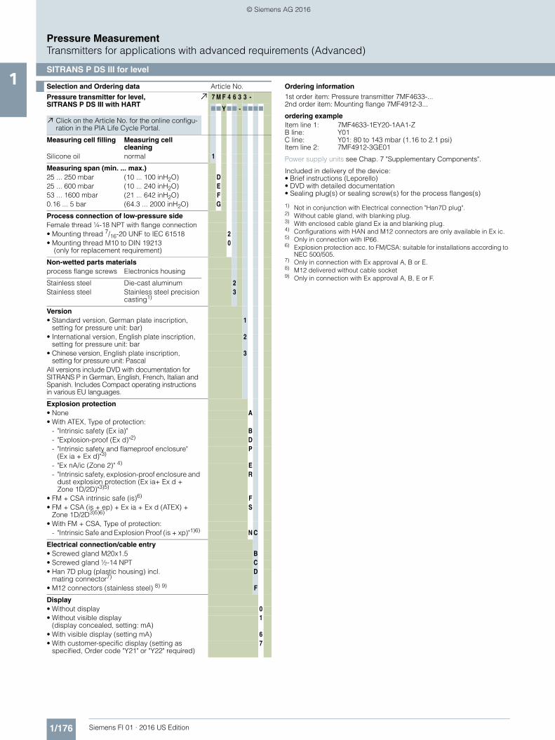
Selection and Ordering data Article No.
Pressure transmitter for level, SITRANS P DS III with HART
7 M F 4 6 3 3 -
77 Y77 - 7777
Click on the Article No. for the online configu-ration in the PIA Life Cycle Portal.
Measuring cell filling Measuring cell cleaning
Silicone oil normal 1
Measuring span (min. ... max.)25 ... 250 mbar (10 ... 100 inH2O) D25 ... 600 mbar (10 ... 240 inH2O) E53 ... 1600 mbar (21 ... 642 inH2O) F0.16 ... 5 bar (64.3 ... 2000 inH2O) G
Process connection of low-pressure sideFemale thread ¼-18 NPT with flange connection• Mounting thread 7/16-20 UNF to IEC 61518 2• Mounting thread M10 to DIN 19213
(only for replacement requirement)0
Non-wetted parts materialsprocess flange screws Electronics housing
Stainless steel Die-cast aluminum 2Stainless steel Stainless steel precision
casting1)3
Version• Standard version, German plate inscription,
setting for pressure unit: bar)1
• International version, English plate inscription, setting for pressure unit: bar
2
• Chinese version, English plate inscription, setting for pressure unit: Pascal
3
All versions include DVD with documentation for SITRANS P in German, English, French, Italian and Spanish. Includes Compact operating instructions in various EU languages.
Explosion protection• None A• With ATEX, Type of protection:
- "Intrinsic safety (Ex ia)" B- "Explosion-proof (Ex d)"2) D- "Intrinsic safety and flameproof enclosure"
(Ex ia + Ex d)"3)P
- "Ex nA/ic (Zone 2)" 4) E- "Intrinsic safety, explosion-proof enclosure and
dust explosion protection (Ex ia+ Ex d + Zone 1D/2D)"3)5)
R
• FM + CSA intrinsic safe (is)6) F• FM + CSA (is + ep) + Ex ia + Ex d (ATEX) +
Zone 1D/2D3)5)6)S
• With FM + CSA, Type of protection:- "Intrinsic Safe and Explosion Proof (is + xp)"1)6) N C
Electrical connection/cable entry• Screwed gland M20x1.5 B• Screwed gland ½-14 NPT C• Han 7D plug (plastic housing) incl.
mating connector7)D
• M12 connectors (stainless steel) 8) 9) F
Display• Without display 0• Without visible display
(display concealed, setting: mA)1
• With visible display (setting mA) 6• With customer-specific display (setting as
specified, Order code "Y21" or "Y22" required)7
Ordering information1st order item: Pressure transmitter 7MF4633-...2nd order item: Mounting flange 7MF4912-3...
ordering exampleItem line 1: 7MF4633-1EY20-1AA1-ZB line: Y01C line: Y01: 80 to 143 mbar (1.16 to 2.1 psi)Item line 2: 7MF4912-3GE01
Power supply units see Chap. 7 "Supplementary Components".
Included in delivery of the device:• Brief instructions (Leporello)• DVD with detailed documentation• Sealing plug(s) or sealing screw(s) for the process flanges(s)
1) Not in conjunction with Electrical connection "Han7D plug".2) Without cable gland, with blanking plug.3) With enclosed cable gland Ex ia and blanking plug.4) Configurations with HAN and M12 connectors are only available in Ex ic.5) Only in connection with IP66.6) Explosion protection acc. to FM/CSA: suitable for installations according to
NEC 500/505.7) Only in connection with Ex approval A, B or E.8) M12 delivered without cable socket9) Only in connection with Ex approval A, B, E or F.
FI01_2016_us_kap01.book Seite 176 Montag, 27. Juni 2016 2:32 14
© Siemens AG 2016
1/177Siemens FI 01 · 2016 US Edition
Pressure MeasurementTransmitters for applications with advanced requirements (Advanced)
SITRANS P DS III for level1
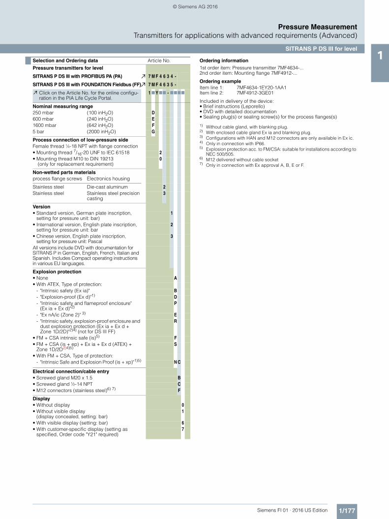
Selection and Ordering data Article No.
Pressure transmitters for level
SITRANS P DS III with PROFIBUS PA (PA) 7 M F 4 6 3 4 -
SITRANS P DS III with FOUNDATION Fieldbus (FF) 7 M F 4 6 3 5 -
Click on the Article No. for the online configu-ration in the PIA Life Cycle Portal.
1 7 Y77 - 7777
Nominal measuring range250 mbar (100 inH2O) D600 mbar (240 inH2O) E1600 mbar (642 inH2O) F5 bar (2000 inH2O) G
Process connection of low-pressure sideFemale thread ¼-18 NPT with flange connection• Mounting thread 7/16-20 UNF to IEC 61518 2• Mounting thread M10 to DIN 19213
(only for replacement requirement)0
Non-wetted parts materialsprocess flange screws Electronics housing
Stainless steel Die-cast aluminum 2Stainless steel Stainless steel precision
casting3
Version• Standard version, German plate inscription,
setting for pressure unit: bar)1
• International version, English plate inscription, setting for pressure unit: bar
2
• Chinese version, English plate inscription, setting for pressure unit: Pascal
3
All versions include DVD with documentation for SITRANS P in German, English, French, Italian and Spanish. Includes Compact operating instructions in various EU languages.
Explosion protection• None A• With ATEX, Type of protection:
- "Intrinsic safety (Ex ia)" B- "Explosion-proof (Ex d)"1) D- "Intrinsic safety and flameproof enclosure"
(Ex ia + Ex d)"2)P
- "Ex nA/ic (Zone 2)" 3) E- "Intrinsic safety, explosion-proof enclosure and
dust explosion protection (Ex ia + Ex d + Zone 1D/2D)"2)4) (not for DS III FF)
R
• FM + CSA intrinsic safe (is)5) F• FM + CSA (is + ep) + Ex ia + Ex d (ATEX) +
Zone 1D/2D2)4)5)S
• With FM + CSA, Type of protection:- "Intrinsic Safe and Explosion Proof (is + xp)"1)5) N C
Electrical connection/cable entry• Screwed gland M20 x 1.5 B• Screwed gland ½-14 NPT C• M12 connectors (stainless steel)6) 7) F
Display• Without display 0• Without visible display
(display concealed, setting: bar)1
• With visible display (setting: bar) 6• With customer-specific display (setting as
specified, Order code "Y21" required)7
Ordering information1st order item: Pressure transmitter 7MF4634-...2nd order item: Mounting flange 7MF4912-...
Ordering exampleItem line 1: 7MF4634-1EY20-1AA1Item line 2: 7MF4912-3GE01
Included in delivery of the device:• Brief instructions (Leporello)• DVD with detailed documentation• Sealing plug(s) or sealing screw(s) for the process flanges(s)
1) Without cable gland, with blanking plug.2) With enclosed cable gland Ex ia and blanking plug.3) Configurations with HAN and M12 connectors are only available in Ex ic.4) Only in connection with IP66.5) Explosion protection acc. to FM/CSA: suitable for installations according to
NEC 500/505.6) M12 delivered without cable socket7) Only in connection with Ex approval A, B, E or F.
FI01_2016_us_kap01.book Seite 177 Montag, 27. Juni 2016 2:32 14
© Siemens AG 2016
1/178 Siemens FI 01 · 2016 US Edition
Pressure MeasurementTransmitters for applications with advanced requirements (Advanced)
SITRANS P DS III for level1
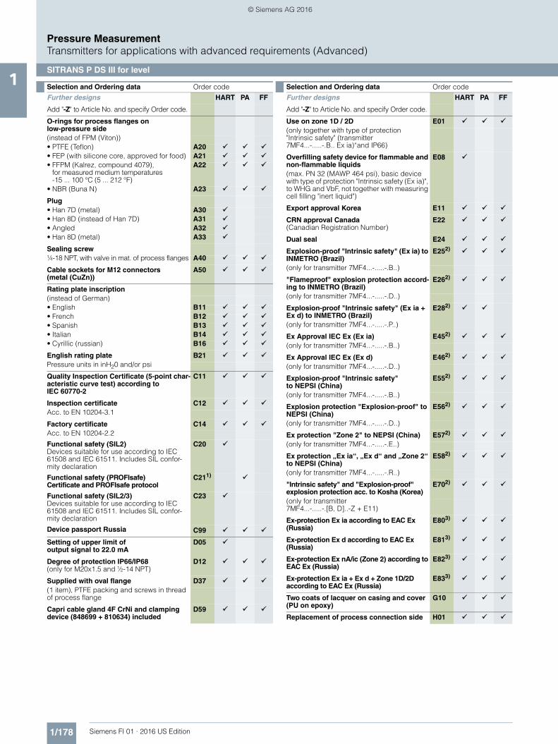
Selection and Ordering data Order code
Further designs HART PA FF
Add "-Z" to Article No. and specify Order code.
O-rings for process flanges on low-pressure side(instead of FPM (Viton))• PTFE (Teflon) A20 • FEP (with silicone core, approved for food) A21 • FFPM (Kalrez, compound 4079),
for measured medium temperatures-15 ... 100 °C (5 ... 212 °F)
A22
• NBR (Buna N) A23
Plug• Han 7D (metal) A30 • Han 8D (instead of Han 7D) A31 • Angled A32 • Han 8D (metal) A33
Sealing screw¼-18 NPT, with valve in mat. of process flanges A40
Cable sockets for M12 connectors (metal (CuZn))
A50
Rating plate inscription(instead of German)• English B11 • French B12 • Spanish B13 • Italian B14 • Cyrillic (russian) B16
English rating plate B21 Pressure units in inH20 and/or psi
Quality Inspection Certificate (5-point char-acteristic curve test) according to IEC 60770-2
C11
Inspection certificate C12 Acc. to EN 10204-3.1
Factory certificate C14 Acc. to EN 10204-2.2
Functional safety (SIL2)Devices suitable for use according to IEC 61508 and IEC 61511. Includes SIL confor-mity declaration
C20
Functional safety (PROFIsafe) Certificate and PROFIsafe protocol
C211)
Functional safety (SIL2/3)Devices suitable for use according to IEC 61508 and IEC 61511. Includes SIL confor-mity declaration
C23
Device passport Russia C99
Setting of upper limit of output signal to 22.0 mA
D05
Degree of protection IP66/IP68(only for M20x1.5 and ½-14 NPT)
D12
Supplied with oval flange D37 (1 item), PTFE packing and screws in thread of process flange
Capri cable gland 4F CrNi and clamping device (848699 + 810634) included
D59
Use on zone 1D / 2D E01 (only together with type of protection "Intrinsic safety" (transmitter 7MF4...-.....-.B.. Ex ia)“and IP66)
Overfilling safety device for flammable and non-flammable liquids
E08
(max. PN 32 (MAWP 464 psi), basic device with type of protection "Intrinsic safety (Ex ia)", to WHG and VbF, not together with measuring cell filling "inert liquid")
Export approval Korea E11
CRN approval Canada(Canadian Registration Number)
E22
Dual seal E24
Explosion-proof "Intrinsic safety" (Ex ia) to INMETRO (Brazil)
E252)
(only for transmitter 7MF4...-.....-.B..)
"Flameproof" explosion protection accord-ing to INMETRO (Brazil)
E262)
(only for transmitter 7MF4...-.....-.D..)
Explosion-proof "Intrinsic safety" (Ex ia + Ex d) to INMETRO (Brazil)
E282)
(only for transmitter 7MF4...-.....-.P..)
Ex Approval IEC Ex (Ex ia) E452) (only for transmitter 7MF4...-.....-.B..)
Ex Approval IEC Ex (Ex d) E462) (only for transmitter 7MF4...-.....-.D..)
Explosion-proof "Intrinsic safety" to NEPSI (China)
E552)
(only for transmitter 7MF4...-.....-.B..)
Explosion protection "Explosion-proof" to NEPSI (China)
E562)
(only for transmitter 7MF4...-.....-.D..)
Ex protection "Zone 2" to NEPSI (China) E572) (only for transmitter 7MF4...-.....-.E..)
Ex protection „Ex ia“, „Ex d“ and „Zone 2“ to NEPSI (China)
E582)
(only for transmitter 7MF4...-.....-.R..)
"Intrinsic safety" and "Explosion-proof" explosion protection acc. to Kosha (Korea)
E702)
(only for transmitter 7MF4...-.....-.[B, D]..-Z + E11)
Ex-protection Ex ia according to EAC Ex (Russia)
E803)
Ex-protection Ex d according to EAC Ex (Russia)
E813)
Ex-protection Ex nA/ic (Zone 2) according to EAC Ex (Russia)
E823)
Ex-protection Ex ia + Ex d + Zone 1D/2D according to EAC Ex (Russia)
E833)
Two coats of lacquer on casing and cover (PU on epoxy)
G10
Replacement of process connection side H01
Selection and Ordering data Order code
Further designs HART PA FF
Add "-Z" to Article No. and specify Order code.
FI01_2016_us_kap01.book Seite 178 Montag, 27. Juni 2016 2:32 14
© Siemens AG 2016

1/179Siemens FI 01 · 2016 US Edition
Pressure MeasurementTransmitters for applications with advanced requirements (Advanced)
SITRANS P DS III for level1
Transient protector 6 kV (lightning protec-tion)
J01
Vent valve or blanking plug of process flange welded-in (orientation: on right when viewing the display)4)
J08
Vent valve or blanking plug of process flange welded-in (orientation: on left when viewing the display)4)
J09
1) Profisafe transmitters can only be operated with the S7 F Systems V6.1 con-figuration software in combination with S7-400H
2) Option does not include ATEX approval, but instead includes only the coun-try-specific approval.
3) Approval pending.4) Blanking plug is standard configuration. Order option A40 if a vent valve is
required instead of a blanking plug.
Selection and Ordering data Order code
Further designs HART PA FF
Add "-Z" to Article No. and specify Order code.
Selection and Ordering data Order code
Additional data HART PA FF
Please add "-Z" to Article No. and specify Order code(s) and plain text.
Measuring range to be set Y01 1)
1) Measuring accuracies for PROFIBUS PA transmitters with Option Y01 are calculated in the same way as for HART devices.
Specify in plain text (max. 5 characters):Y01: ... up to ... mbar, bar, kPa, MPa, psi
Stainless steel tag plate and entry in device variable (measuring point descrip-tion)
Y15
Max. 16 characters, specify in plain text:Y15: ...........................................
Measuring point text (entry in device vari-able)
Y16
Max. 27 characters, specify in plain text:Y16: ...........................................
Entry of HART address (TAG) Y17 Max. 8 characters, specify in plain text:Y17: ...........................................
Setting of pressure indicator in pressure units
Y21
Specify in plain text (standard setting: bar):Y21: mbar, bar, kPa, MPa, psi, ...Note:The following pressure units can be selected:bar, mbar, mm H2O*), inH2O*), ftH2O*), mmHG, inHG, psi, Pa, kPa, MPa, g/cm2, kg/cm2, Torr, ATM or % *) ref. temperature 20 °C
Setting of pressure indicator in non-pressure units2)
2) Preset values can only be changed over SIMATIC PDM.
Y223)
+ Y01
3) Not in conjunction with over-filling safety device for flammable and non-flammable liquids (Order code "E08")
Specify in plain text:Y22: ..... up to ..... l/min, m3/h, m, USgpm, ...(specification of measuring range in pressure units "Y01" is essential, unit with max. 5 characters)
Preset bus address Y25 possible between 1 and 126Specify in plain text: Y25: ...........................................
Damping adjustment in seconds(0 ... 100 s)
Y30
Only Y01, Y15, Y16, Y17, Y21, Y22, Y25 and D05 can be factory preset
= available
FI01_2016_us_kap01.book Seite 179 Montag, 27. Juni 2016 2:32 14
© Siemens AG 2016
1/180 Siemens FI 01 · 2016 US Edition
Pressure MeasurementTransmitters for applications with advanced requirements (Advanced)
SITRANS P DS III for level1
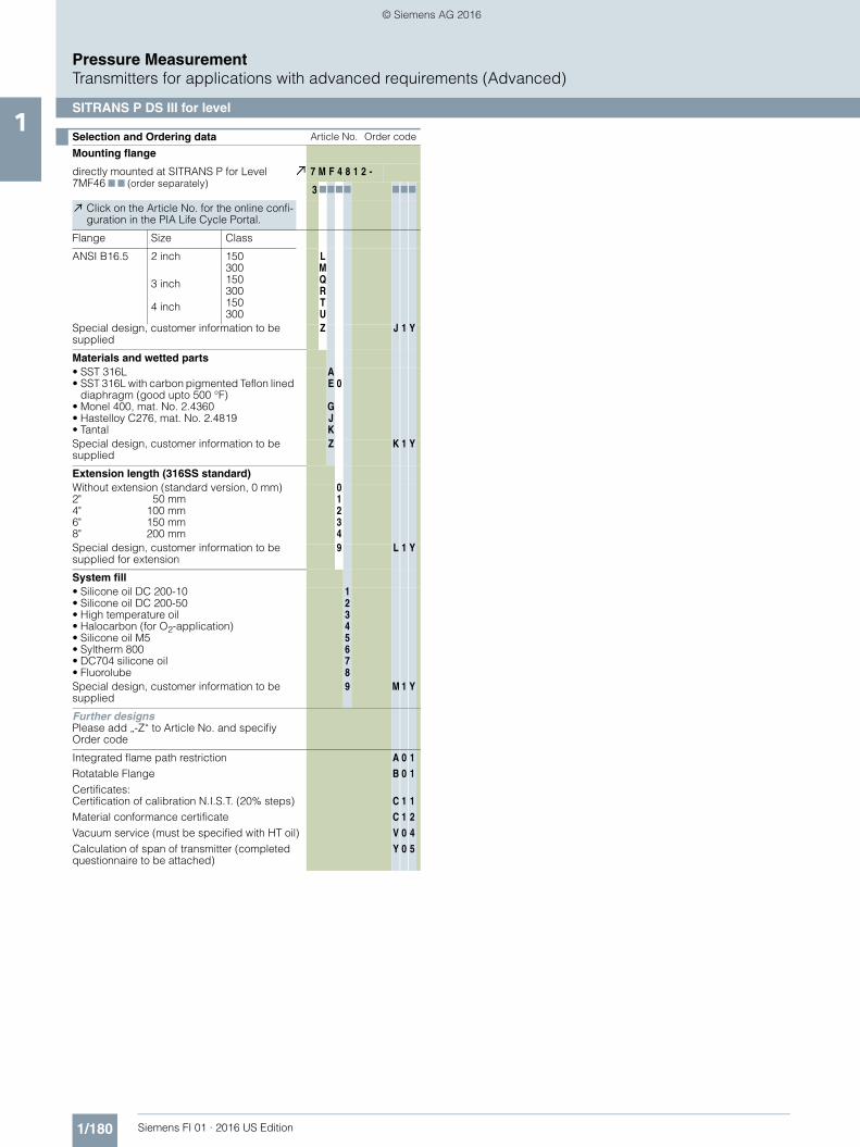
Selection and Ordering data Article No. Order code
Mounting flange
directly mounted at SITRANS P for Level 7MF46 7 7 (order separately)
7 M F 4 8 1 2 -
3 7777 777
Click on the Article No. for the online confi-guration in the PIA Life Cycle Portal.
Flange Size Class
ANSI B16.5 2 inch
3 inch
4 inch
150300150300150300
LMQRTU
Special design, customer information to be supplied
Z J 1 Y
Materials and wetted parts• SST 316L• SST 316L with carbon pigmented Teflon lined
diaphragm (good upto 500 °F)• Monel 400, mat. No. 2.4360• Hastelloy C276, mat. No. 2.4819• Tantal
AE
GJK
0
Special design, customer information to be supplied
Z K 1 Y
Extension length (316SS standard)Without extension (standard version, 0 mm)2" 50 mm4" 100 mm6" 150 mm8" 200 mm
01234
Special design, customer information to be supplied for extension
9 L 1 Y
System fill• Silicone oil DC 200-10• Silicone oil DC 200-50• High temperature oil• Halocarbon (for O2-application)• Silicone oil M5• Syltherm 800• DC704 silicone oil• Fluorolube
12345678
Special design, customer information to be supplied
9 M 1 Y
Further designsPlease add „-Z“ to Article No. and specifiy Order code
Integrated flame path restrictionRotatable FlangeCertificates:Certification of calibration N.I.S.T. (20% steps)Material conformance certificateVacuum service (must be specified with HT oil)Calculation of span of transmitter (completed questionnaire to be attached)
A
B
C
C
V
Y
0
0
1
1
0
0
1
1
1
2
4
5
FI01_2016_us_kap01.book Seite 180 Montag, 27. Juni 2016 2:32 14
© Siemens AG 2016
1/181Siemens FI 01 · 2016 US Edition
Pressure MeasurementTransmitters for applications with advanced requirements (Advanced)
SITRANS P DS III for level1
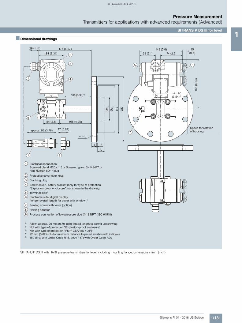
■ Dimensional drawings
SITRANS P DS III with HART pressure transmitters for level, including mounting flange, dimensions in mm (inch)
11
8
3
2
4
1
5 6
7
9
1) Allow approx. 20 mm (0.79 inch) thread length to permit unscrewing2) Not with type of protection "Explosion-proof enclosure"3) Not with type of protection "FM + CSA" [IS + XP]"4) 92 mm (3.62 inch) for minimum distance to permit rotation with indicator5) 150 (5.9) with Order Code R15, 200 (7.87) with Order Code R20
1
Protective cover over keys2
Blanking plug
Electrical connection:Screwed gland M20 x 1,5 or Screwed gland ½-14 NPT or Han 7D/Han 8D2) 3) plug
3
Screw cover - safety bracket (only for type of protection "Explosion-proof enclosure", not shown in the drawing)
4
Electronic side, digital display (longer overall length for cover with window)1)
Terminal side1)5
Sealing screw with valve (option)
6
7
Harting adapter89 Process connection of low pressure side ¼-18 NPT (IEC 61518)
approx. 96 (3.78)
min. 90 (3.54)4)
Space for rotation of housing
84 (3.31)177 (6.97)
74 (2.9)143 (5.6) 15
(0.6)53 (2.1)
29 (1.14)
17 (0.67)
166
(6.5
4)
ØD
Øk
Ød 4
Ød 5
bLf
n x d2
108 (4.25)54 (2.1)
100 (3.93)5)
FI01_2016_us_kap01.book Seite 181 Montag, 27. Juni 2016 2:32 14
© Siemens AG 2016
1/182 Siemens FI 01 · 2016 US Edition
Pressure MeasurementTransmitters for applications with advanced requirements (Advanced)
SITRANS P DS III for level1
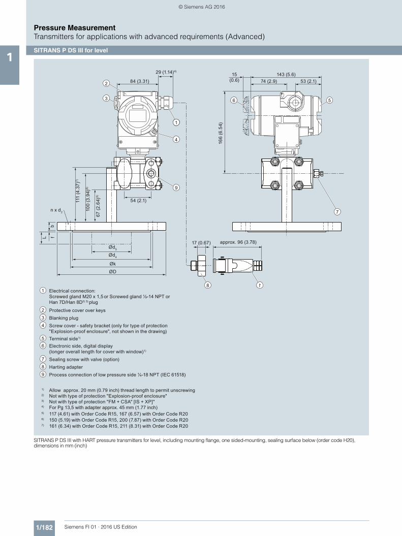
SITRANS P DS III with HART pressure transmitters for level, including mounting flange, one sided-mounting, sealing surface below (order code H20),dimensions in mm (inch)
11
3
2
4
9
56
7
8 1
1) Allow approx. 20 mm (0.79 inch) thread length to permit unscrewing2) Not with type of protection "Explosion-proof enclosure"3) Not with type of protection "FM + CSA" [IS + XP]"4) For Pg 13,5 with adapter approx. 45 mm (1.77 inch)5)
6)117 (4.61) with Order Code R15, 167 (6.57) with Order Code R20150 (5.19) with Order Code R15, 200 (7.87) with Order Code R20
7) 161 (6.34) with Order Code R15, 211 (8.31) with Order Code R20
1
Protective cover over keys2
Blanking plug
Electrical connection:Screwed gland M20 x 1,5 or Screwed gland ½-14 NPT or Han 7D/Han 8D2) 3) plug
3
Screw cover - safety bracket (only for type of protection "Explosion-proof enclosure", not shown in the drawing)
4
Electronic side, digital display (longer overall length for cover with window)1)
Terminal side1)5
Sealing screw with valve (option)
6
7
Harting adapter89 Process connection of low pressure side ¼-18 NPT (IEC 61518)
approx. 96 (3.78)
ØDØk
Ød4
Ød5
bL f
n x d2
53 (2.1)143 (5.6)
74 (2.9)15
(0.6)84 (3.31)
29 (1.14)4)
54 (2.1)
17 (0.67)
100
(3.9
4)6)
111
(4.3
7)7)
67 (2
.64)
5)
166
(6.5
4)
FI01_2016_us_kap01.book Seite 182 Montag, 27. Juni 2016 2:32 14
© Siemens AG 2016
1/183Siemens FI 01 · 2016 US Edition
Pressure MeasurementTransmitters for applications with advanced requirements (Advanced)
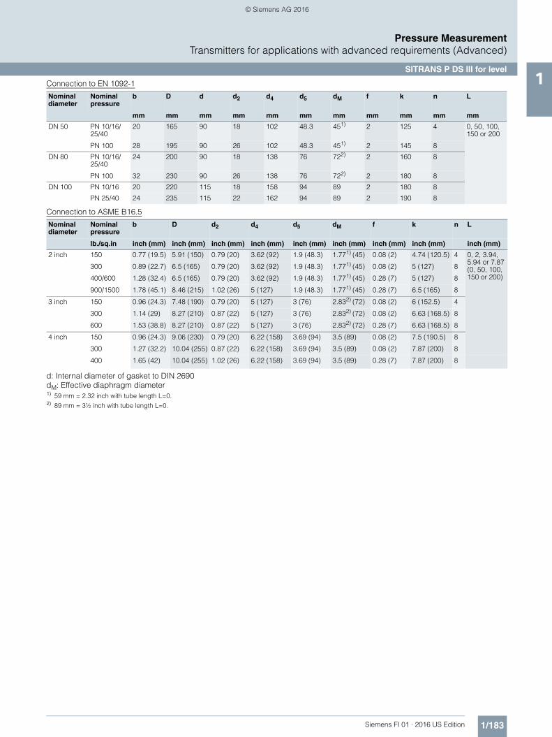
SITRANS P DS III for level1Connection to EN 1092-1
Connection to ASME B16.5
d: Internal diameter of gasket to DIN 2690dM: Effective diaphragm diameter1) 59 mm = 2.32 inch with tube length L=0.2) 89 mm = 3½ inch with tube length L=0.
Nominal diameter
Nominal pressure
b D d d2 d4 d5 dM f k n L
mm mm mm mm mm mm mm mm mm mm mm
DN 50 PN 10/16/25/40
20 165 90 18 102 48.3 451) 2 125 4 0, 50, 100, 150 or 200
PN 100 28 195 90 26 102 48.3 451) 2 145 8
DN 80 PN 10/16/25/40
24 200 90 18 138 76 722) 2 160 8
PN 100 32 230 90 26 138 76 722) 2 180 8
DN 100 PN 10/16 20 220 115 18 158 94 89 2 180 8
PN 25/40 24 235 115 22 162 94 89 2 190 8
Nominal diameter
Nominal pressure
b D d2 d4 d5 dM f k n L
lb./sq.in inch (mm) inch (mm) inch (mm) inch (mm) inch (mm) inch (mm) inch (mm) inch (mm) inch (mm)
2 inch 150 0.77 (19.5) 5.91 (150) 0.79 (20) 3.62 (92) 1.9 (48.3) 1.771) (45) 0.08 (2) 4.74 (120.5) 4 0, 2, 3.94, 5.94 or 7.87(0, 50, 100, 150 or 200)
300 0.89 (22.7) 6.5 (165) 0.79 (20) 3.62 (92) 1.9 (48.3) 1.771) (45) 0.08 (2) 5 (127) 8
400/600 1.28 (32.4) 6.5 (165) 0.79 (20) 3.62 (92) 1.9 (48.3) 1.771) (45) 0.28 (7) 5 (127) 8
900/1500 1.78 (45.1) 8.46 (215) 1.02 (26) 5 (127) 1.9 (48.3) 1.771) (45) 0.28 (7) 6.5 (165) 8
3 inch 150 0.96 (24.3) 7.48 (190) 0.79 (20) 5 (127) 3 (76) 2.832) (72) 0.08 (2) 6 (152.5) 4
300 1.14 (29) 8.27 (210) 0.87 (22) 5 (127) 3 (76) 2.832) (72) 0.08 (2) 6.63 (168.5) 8
600 1.53 (38.8) 8.27 (210) 0.87 (22) 5 (127) 3 (76) 2.832) (72) 0.28 (7) 6.63 (168.5) 8
4 inch 150 0.96 (24.3) 9.06 (230) 0.79 (20) 6.22 (158) 3.69 (94) 3.5 (89) 0.08 (2) 7.5 (190.5) 8
300 1.27 (32.2) 10.04 (255) 0.87 (22) 6.22 (158) 3.69 (94) 3.5 (89) 0.08 (2) 7.87 (200) 8
400 1.65 (42) 10.04 (255) 1.02 (26) 6.22 (158) 3.69 (94) 3.5 (89) 0.28 (7) 7.87 (200) 8
FI01_2016_us_kap01.book Seite 183 Montag, 27. Juni 2016 2:32 14
© Siemens AG 2016