Embed Size (px)
Citation preview

Pressure Reducing Valve DMV 755set range: 1,0 - 9,0 bar
Advantage• pressure setting possible at any time, also during operation• high reproducibility of the set pressure• high level of operating safety and long service life• constant, low vibration control• low-maintenance• hermetically sealed by valve diaphragm with formed sealing
rings• considerably shortened face-to-face dimension with injection
moulded threaded neck according to DIN 8063• metal inserts in the valve housing allow the valves to be directly
fitted to mounting sets, the movability of the union nuts on thevalves made of PVC-U, PP and PVDF remains unaffected
Application• chemical plants• industrial plants• water treatment
Utilisation• The pressure reducing valve which is directly controlled by the
medium, is used in technical processing plants for reducingprimary pressures to system dependent working pressures andfor controlled maintenance of working pressures.
Valve Function• The opened valve is in equilibrium between the inlet pressure
(primary side) and the lower working pressure (secondary side).If the working pressure goes above or below the desired value,the large area membrane is lifted against the spring force orpressed down by the spring force. The valve starts closing oropening until the equilibrium condition is reached again, i.e.the working pressure remains constant independent of anincreasing or decreasing inlet pressure (as long as the inletpressure > working pressure).
Valve Setting• Set or adjust the working pressure to be kept constant at the
adjustment screw with the aid of pressure gauges (ASVdiaphragm pressure gauge guard with pressure gauge, type MDM902) in the pipe system after removing the protection cap. Theadjustment screw is secured by a counter nut and can be sealedagainst unauthorized adjustment, if necessary.
• There are two types of application:· secondary pressure - system closed or· secondary pressure - system dynamically flowing
Flow Media• Technically pure, neutral and aggressive fluids, provided that
the selected valve materials coming into contact with the mediaare resistant at the operating temperature according to the ASVresistance guide.
• For nitric acid or sulfuric acid please specify the precise operatingconditions of the application.
Fluid Temperature• see pressure/temperature diagram
Operating Pressure• see pressure/temperature diagram
Set Range• 1.0 - 9.0 bar
Nominal Pressure (H2O, 20°C)• PN 10
Working Pressure• set pressure minus flow dependent pressure reduction:• secondary pressure• 1,0 - 9,0 bar
Constant Working Pressure• Difference between the maximum and minimum secondary
pressure, caused by primary pressure fluctuations:• approx. ± 0.2 bar
Hysteresis• Difference between opening and closing pressure• approx. 0.1 - 0.4 bar
Valve Body• PVC-U• PP• PVDF
Bonnet• PP, glass fibre reinforced
Diaphragm• PTFE (EPDM diaphragm with PTFE coating on the surfaces coming
into contact with the medium)
Sealing• FPM• EPDM
Screws• stainless steel (1.4301)
1All rights for technical modifications withheld> data sheet no.: 330154 - 2009/01/01ASV Stübbe GmbH & Co. KG · Hollwieser Str. 5 · D-32602 Vlotho · Tel. +49(0)5733. 799-0 · Fax +49(0)5733. 799-5000 · [email protected] · www.asv-stuebbe.de

Actuation• medium controlled
Connection• union DIN 8063• union socket end for solvent welding DIN ISO (PVC-U)• union socket end for fusion welding DIN ISO (PP)• union socket end for fusion welding DIN ISO (PVDF)• spigot end for solvent welding DIN ISO (PVC-U)• fusion spigot end DIN ISO (PP)• fusion spigot end DIN ISO (PVDF)• backing flange DIN 2501, PN 10/16, on request
Flow Direction• always in the direction of the arrow
Mounting• as required
Colour• bonnet: orange, RAL 2004• bottom section: PVC-U, grey, RAL 7011• bottom section: PP, grey, RAL 7032• bottom section: PVDF, opaque, yellowish-white
Pressure Gauge Connection• The pressure reducing valves can be factory fitted with a pressure
gauge for neutral media. The resistance of the pressure gaugematerial has to be taken into consideration for other media.
> data sheet no.: 330154 - 2009/01/01All rights for technical modifications withheld2ASV Stübbe GmbH & Co. KG · Hollwieser Str. 5 · D-32602 Vlotho · Tel. +49(0)5733. 799-0 · Fax +49(0)5733. 799-5000 · [email protected] · www.asv-stuebbe.de

Pressure/temperature diagram
P = operating pressureT = temperatureThe pressure/temperature limits are applicable for the statednominal pressures and a computed operating life factor of 25 years.These are standard values for harmless media (DIN 2403), to whichthe valve material is resistant.For other media please refer to the ASV resistance guide.The durability of wear parts depends on the operating conditionsof the application.For temperatures below 0°C (PP < +10°C) please specify the preciseoperating conditions of the application.The rated pressure depends on the valve size and material. Forthe corresponding rated pressure value of the valve, please referto the »Order table«.
Operating behaviour
pE = set pressurepA = working pressurepÖ = opening pressurepS = closing pressurepÖ - pS = hysteresispA - pE = flow dependent pressure reductionQ = flow
3All rights for technical modifications withheld> data sheet no.: 330154 - 2009/01/01ASV Stübbe GmbH & Co. KG · Hollwieser Str. 5 · D-32602 Vlotho · Tel. +49(0)5733. 799-0 · Fax +49(0)5733. 799-5000 · [email protected] · www.asv-stuebbe.de
Pressure reducing valves, Pressure Reducing Valve DMV 755

Sectional drawing
A = primary sideB = secondary side1 = protection cap2 = adjustment screw3 = counter nut4 = piston5= diaphragm6 = flat sealing ring7 = valve seat8 = control bore hole
ApplicationsSecondary pressure - System dynamically flowing
pP = pump pressurepA = working pressure1 = Pressure Reducing Valve2 = stop valve3 = Pressure Relief ValveIf the stop valve is closed, the working pressure pA rises by theamount of the closing pressure pS.
ApplicationsSecondary pressure - System closed
pP = pump pressurepA = working pressure1 = Pressure Reducing Valve2 = stop valve3 = Pressure Relief ValveIf the stop valve is opened, the working pressure pA drops by theamount of the opening pressure pÖ.
> data sheet no.: 330154 - 2009/01/01All rights for technical modifications withheld4ASV Stübbe GmbH & Co. KG · Hollwieser Str. 5 · D-32602 Vlotho · Tel. +49(0)5733. 799-0 · Fax +49(0)5733. 799-5000 · [email protected] · www.asv-stuebbe.de
Pressure reducing valves, Pressure Reducing Valve DMV 755
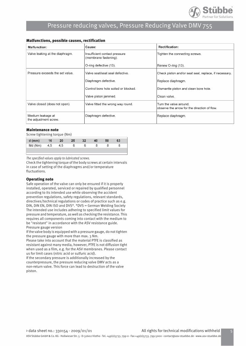
Malfunctions, possible causes, rectification
Maintenance noteScrew tightening torque (Nm)
The specified values apply to lubricated screws.Check the tightening torque of the body screws at certain intervalsin case of setting of the diaphragms and/or temperaturefluctuations.
Operating noteSafe operation of the valve can only be ensured if it is properlyinstalled, operated, serviced or repaired by qualified personnelaccording to its intended use while observing the accidentprevention regulations, safety regulations, relevant standards,directives/technical regulations or codes of practice such as e.g.DIN, DIN EN, DIN ISO and DVS*. *DVS = German Welding SocietyThe intended use includes adhering to specified limit values forpressure and temperature, as well as checking the resistance. Thisrequires all components coming into contact with the medium tobe "resistant" in accordance with the ASV resistance guide.Pressure gauge versionIf the valve body is equipped with a pressure gauge, do not tightenthe pressure gauge with more than max. 3 Nm.Please take into account that the material PTFE is classified asresistant against many media, however, PTFE is not diffusion tightwhen used as a film, e.g. for the ASV membranes. Please contactus for limit cases (nitric acid or sulfuric acid).If the secondary pressure is additionally increased by thecounterpressure, the pressure reducing valve DMV acts as anon-return valve. This force can lead to destruction of the valvepiston.
5All rights for technical modifications withheld> data sheet no.: 330154 - 2009/01/01ASV Stübbe GmbH & Co. KG · Hollwieser Str. 5 · D-32602 Vlotho · Tel. +49(0)5733. 799-0 · Fax +49(0)5733. 799-5000 · [email protected] · www.asv-stuebbe.de
Pressure reducing valves, Pressure Reducing Valve DMV 755

body PVC-U
63504032252016d(mm)sizepressure range 50403225201510DN(mm)
21 1/21 1/413/41/23/8DN(inch)10101010101010PN(bar)
1-91-91-91-91-91-91-9setting range (bar)
ident No.sealingConnection
119306119305119304119303119302119301119300EPDMPVC-Usocket end DIN ISO 119313
5.20 kg1193125.10 kg
1193115.00 kg
1193101.90 kg
1193091.90 kg
1193080.90 kg
1193070.80 kg
FPMweight
122054122053122052122051122050122049122048EPDMPVC-Uspigot end DIN ISO 122061
5.20 kg1220605.10 kg
1220595.00 kg
1220581.90 kg
1220571.90 kg
1220560.90 kg
1220550.80 kg
FPMweight
body PP
63504032252016d(mm)sizepressure range 50403225201510DN(mm)
21 1/21 1/413/41/23/8DN(inch)10101010101010PN(bar)
1-91-91-91-91-91-91-9setting range (bar)
ident No.sealingConnection
119320119319119318119317119316119315119314EPDMPPsocket end DIN ISO 119327
4.30 kg1193264.20 kg
1193254.10 kg
1193241.60 kg
1193231.60 kg
1193220.70 kg
1193210.70 kg
FPMweight
122068122067122066122065122064122063122062EPDMPPspigot end DIN ISO 122075
4.30 kg1220744.20 kg
1220734.10 kg
1220721.60 kg
1220711.60 kg
1220700.70 kg
1220690.70 kg
FPMweight
> data sheet no.: 330154 - 2009/01/01All rights for technical modifications withheld6ASV Stübbe GmbH & Co. KG · Hollwieser Str. 5 · D-32602 Vlotho · Tel. +49(0)5733. 799-0 · Fax +49(0)5733. 799-5000 · [email protected] · www.asv-stuebbe.de
Pressure reducing valves, Pressure Reducing Valve DMV 755

body PVDF
63504032252016d(mm)sizepressure range 50403225201510DN(mm)
21 1/21 1/413/41/23/8DN(inch)10101010101010PN(bar)
1-91-91-91-91-91-91-9setting range (bar)
ident No.sealingConnection
1193415.70 kg
1193405.60 kg
1193395.50 kg
1193382.20 kg
1193372.10 kg
1193361.10 kg
1193351.00 kg
FPMweight
PVDFsocket end DIN ISO
1220895.70 kg
1220885.60 kg
1220875.50 kg
1220862.20 kg
1220852.10 kg
1220841.10 kg
1220831.00 kg
FPMweight
PVDFspigot end DIN ISO
7All rights for technical modifications withheld> data sheet no.: 330154 - 2009/01/01ASV Stübbe GmbH & Co. KG · Hollwieser Str. 5 · D-32602 Vlotho · Tel. +49(0)5733. 799-0 · Fax +49(0)5733. 799-5000 · [email protected] · www.asv-stuebbe.de
Pressure reducing valves, Pressure Reducing Valve DMV 755

dimensions
63504032252016d(mm)50403225201510DN(mm)
21 1/21 1/413/41/23/8DN(inch)
dimensions(mm)
63504032252016d57575737372525hPP/PVC-U54545436362424hPVDF
244224224174174144144L1205205205150150120120L2PP/PVC-U200200200147147120118L2PVDF211211211156156126126L3PP/PVC-U207207207153153124124L3PVDF
38312622191614t262262262202202174174H1471471471071078181N65656546464040V
> data sheet no.: 330154 - 2009/01/01All rights for technical modifications withheld8ASV Stübbe GmbH & Co. KG · Hollwieser Str. 5 · D-32602 Vlotho · Tel. +49(0)5733. 799-0 · Fax +49(0)5733. 799-5000 · [email protected] · www.asv-stuebbe.de
Pressure reducing valves, Pressure Reducing Valve DMV 755
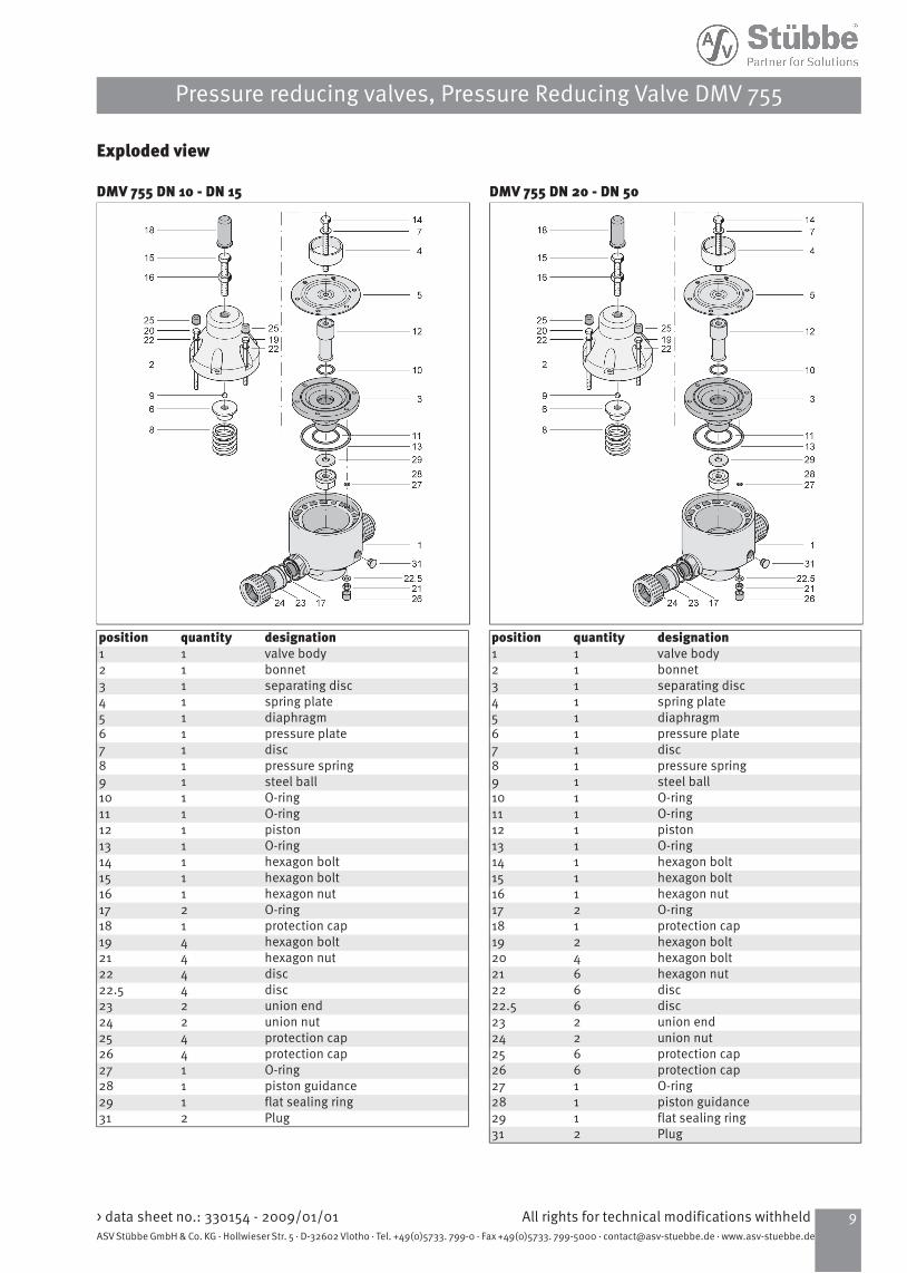
Exploded view
DMV 755 DN 10 - DN 15
designationquantitypositionvalve body11bonnet12separating disc13spring plate14diaphragm15pressure plate16disc17pressure spring18steel ball19O-ring110O-ring111piston112O-ring113hexagon bolt114hexagon bolt115hexagon nut116O-ring217protection cap118hexagon bolt419hexagon nut421disc422disc422.5union end223union nut224protection cap425protection cap426O-ring127piston guidance128flat sealing ring129Plug231
DMV 755 DN 20 - DN 50
designationquantitypositionvalve body11bonnet12separating disc13spring plate14diaphragm15pressure plate16disc17pressure spring18steel ball19O-ring110O-ring111piston112O-ring113hexagon bolt114hexagon bolt115hexagon nut116O-ring217protection cap118hexagon bolt219hexagon bolt420hexagon nut621disc622disc622.5union end223union nut224protection cap625protection cap626O-ring127piston guidance128flat sealing ring129Plug231
9All rights for technical modifications withheld> data sheet no.: 330154 - 2009/01/01ASV Stübbe GmbH & Co. KG · Hollwieser Str. 5 · D-32602 Vlotho · Tel. +49(0)5733. 799-0 · Fax +49(0)5733. 799-5000 · [email protected] · www.asv-stuebbe.de
Pressure reducing valves, Pressure Reducing Valve DMV 755

Characteristic curvesConfiguration example
The valve is set tight at 5 bar.Desired flow rate 8000 l/h, Medium H²OAccording to the curve, this results in the following values:set pressure pE: 5 bar; Pressure reduction: p = 0,8 bar; Working pressure pA = 4,4 barDN 10
pA = working pressure (secondary pressure)Q = flow
DN 15
pA = working pressure (secondary pressure)Q = flow
DN 20
pA = working pressure (secondary pressure)Q = flow
DN 25
pA = working pressure (secondary pressure)Q = flow
> data sheet no.: 330154 - 2009/01/01All rights for technical modifications withheld10ASV Stübbe GmbH & Co. KG · Hollwieser Str. 5 · D-32602 Vlotho · Tel. +49(0)5733. 799-0 · Fax +49(0)5733. 799-5000 · [email protected] · www.asv-stuebbe.de
Pressure reducing valves, Pressure Reducing Valve DMV 755

DN 32
pA = working pressure (secondary pressure)Q = flow
DN 40
pA = working pressure (secondary pressure)Q = flow
DN 50
pA = working pressure (secondary pressure)Q = flow
11All rights for technical modifications withheld> data sheet no.: 330154 - 2009/01/01ASV Stübbe GmbH & Co. KG · Hollwieser Str. 5 · D-32602 Vlotho · Tel. +49(0)5733. 799-0 · Fax +49(0)5733. 799-5000 · [email protected] · www.asv-stuebbe.de
Pressure reducing valves, Pressure Reducing Valve DMV 755

> data sheet no.: 330154 - 2009/01/01All rights for technical modifications withheld12ASV Stübbe GmbH & Co. KG · Hollwieser Str. 5 · D-32602 Vlotho · Tel. +49(0)5733. 799-0 · Fax +49(0)5733. 799-5000 · [email protected] · www.asv-stuebbe.de
Pressure reducing valves, Pressure Reducing Valve DMV 755

Pressure Reducing Valve DMV 765set range: 0,5 - 9,0 bar
Advantage• pressure setting possible at any time, also during operation• high reproducibility of the set pressure• high level of operating safety and long service life• constant, low vibration control• low-maintenance• hermetically sealed by valve diaphragm with formed sealing
rings• considerably shortened face-to-face dimension with injection
moulded threaded neck according to DIN 8063• metal inserts in the valve housing allow the valves to be directly
fitted to mounting sets, the movability of the union nuts on thevalves made of PVC-U, PP and PVDF remains unaffected
Application• chemical plants• industrial plants• water treatment
Utilisation• The pressure reducing valve which is directly controlled by the
medium, is used in technical processing plants for reducingprimary pressures to system dependent working pressures andfor controlled maintenance of working pressures.
Valve Function• The opened valve is in equilibrium between the inlet pressure
(primary side) and the lower working pressure (secondary side).If the working pressure goes above or below the desired value,the large area membrane is lifted against the spring force orpressed down by the spring force. The valve starts closing oropening until the equilibrium condition is reached again, i.e.the working pressure remains constant independent of anincreasing or decreasing inlet pressure (as long as the inletpressure > working pressure).
Valve Setting• Set or adjust the working pressure to be kept constant at the
adjustment screw with the aid of pressure gauges (ASVdiaphragm pressure gauge guard with pressure gauge, type MDM902) in the pipe system after removing the protection cap. Theadjustment screw is secured by a counter nut and can be sealedagainst unauthorized adjustment, if necessary.
• There are two types of application:· secondary pressure - system closed or· secondary pressure - system dynamically flowing
Flow Media• Technically pure, neutral and aggressive fluids, provided that
the selected valve materials coming into contact with the mediaare resistant at the operating temperature according to the ASVresistance guide.
• For nitric acid or sulfuric acid please specify the precise operatingconditions of the application.
Fluid Temperature• see pressure/temperature diagram
Operating Pressure• see pressure/temperature diagram
Set Range• 0.5 - 9.0 bar
Nominal Pressure (H2O, 20°C)• PN 10
Working Pressure• set pressure minus flow dependent pressure reduction:• secondary pressure• 0,5 - 9,0 bar
Constant Working Pressure• Difference between the maximum and minimum secondary
pressure, caused by primary pressure fluctuations:• approx. ± 0.2 bar
Hysteresis• Difference between opening and closing pressure• approx. 0.1 - 0.4 bar
Valve Body• PVC-U• PP• PVDF
Bonnet• PP, glass fibre reinforced
Diaphragm• PTFE (EPDM diaphragm with PTFE coating on the surfaces coming
into contact with the medium)
Sealing• FPM• EPDM
Screws• stainless steel (1.4301)
1All rights for technical modifications withheld> data sheet no.: 330154 - 2009/01/01ASV Stübbe GmbH & Co. KG · Hollwieser Str. 5 · D-32602 Vlotho · Tel. +49(0)5733. 799-0 · Fax +49(0)5733. 799-5000 · [email protected] · www.asv-stuebbe.de

Actuation• medium controlled
Connection• union DIN 8063• union socket end for solvent welding DIN ISO (PVC-U)• union socket end for fusion welding DIN ISO (PP)• union socket end for fusion welding DIN ISO (PVDF)• spigot end for solvent welding DIN ISO (PVC-U)• fusion spigot end DIN ISO (PP)• fusion spigot end DIN ISO (PVDF)• backing flange DIN 2501, PN 10/16, on request
Flow Direction• always in the direction of the arrow
Mounting• as required
Colour• bonnet: orange, RAL 2004• bottom section: PVC-U, grey, RAL 7011• bottom section: PP, grey, RAL 7032• bottom section: PVDF, opaque, yellowish-white
Pressure Gauge Connection• The pressure reducing valves can be factory fitted with a pressure
gauge for neutral media. The resistance of the pressure gaugematerial has to be taken into consideration for other media.
> data sheet no.: 330154 - 2009/01/01All rights for technical modifications withheld2ASV Stübbe GmbH & Co. KG · Hollwieser Str. 5 · D-32602 Vlotho · Tel. +49(0)5733. 799-0 · Fax +49(0)5733. 799-5000 · [email protected] · www.asv-stuebbe.de

Pressure/temperature diagram
P = operating pressureT = temperatureThe pressure/temperature limits are applicable for the statednominal pressures and a computed operating life factor of 25 years.These are standard values for harmless media (DIN 2403), to whichthe valve material is resistant.For other media please refer to the ASV resistance guide.The durability of wear parts depends on the operating conditionsof the application.For temperatures below 0°C (PP < +10°C) please specify the preciseoperating conditions of the application.The rated pressure depends on the valve size and material. Forthe corresponding rated pressure value of the valve, please referto the »Order table«.
Operating behaviour
pE = set pressurepA = working pressurepÖ = opening pressurepS = closing pressurepÖ - pS = hysteresispA - pE = flow dependent pressure reductionQ = flow
3All rights for technical modifications withheld> data sheet no.: 330154 - 2009/01/01ASV Stübbe GmbH & Co. KG · Hollwieser Str. 5 · D-32602 Vlotho · Tel. +49(0)5733. 799-0 · Fax +49(0)5733. 799-5000 · [email protected] · www.asv-stuebbe.de
Pressure reducing valves, Pressure Reducing Valve DMV 765

Sectional drawing DMV 765
A = primary sideB = secondary side1 = protection cap2 = adjustment screw3 = counter nut4 = piston5= diaphragm6 = flat sealing ring7 = valve seat8 = control bore hole
Applicationssecondary pressure - system dynamically flowing
pP = pump pressurepA = working pressure1 = Pressure Reducing Valve2 = stop valve3 = Pressure Relief ValveIf the stop valve is closed, the working pressure pA rises by theamount of the closing pressure pS.
ApplicationsSecondary pressure - System closed
pP = pump pressurepA = working pressure1 = Pressure Reducing Valve2 = stop valve3 = Pressure Relief ValveIf the stop valve is opened, the working pressure pA drops by theamount of the opening pressure pÖ.
> data sheet no.: 330154 - 2009/01/01All rights for technical modifications withheld4ASV Stübbe GmbH & Co. KG · Hollwieser Str. 5 · D-32602 Vlotho · Tel. +49(0)5733. 799-0 · Fax +49(0)5733. 799-5000 · [email protected] · www.asv-stuebbe.de
Pressure reducing valves, Pressure Reducing Valve DMV 765

Malfunctions, possible causes, rectification
Maintenance noteScrew tightening torque (Nm)
The specified values apply to lubricated screws.Check the tightening torque of the body screws at certain intervalsin case of setting of the diaphragms and/or temperaturefluctuations.
Operating noteSafe operation of the valve can only be ensured if it is properlyinstalled, operated, serviced or repaired by qualified personnelaccording to its intended use while observing the accidentprevention regulations, safety regulations, relevant standards,directives/technical regulations or codes of practice such as e.g.DIN, DIN EN, DIN ISO and DVS*. *DVS = German Welding SocietyThe intended use includes adhering to specified limit values forpressure and temperature, as well as checking the resistance. Thisrequires all components coming into contact with the medium tobe "resistant" in accordance with the ASV resistance guide.Pressure gauge versionIf the valve body is equipped with a pressure gauge, do not tightenthe pressure gauge with more than max. 3 Nm.If the secondary pressure is additionally increased by thecounterpressure, the pressure reducing valve DMV acts as anon-return valve. This force can lead to destruction of the valvepiston.Please take into account that the material PTFE is classified asresistant against many media, however, PTFE is not diffusion tightwhen used as a film, e.g. for the ASV membranes. Please contactus for limit cases (nitric acid or sulfuric acid).
5All rights for technical modifications withheld> data sheet no.: 330154 - 2009/01/01ASV Stübbe GmbH & Co. KG · Hollwieser Str. 5 · D-32602 Vlotho · Tel. +49(0)5733. 799-0 · Fax +49(0)5733. 799-5000 · [email protected] · www.asv-stuebbe.de
Pressure reducing valves, Pressure Reducing Valve DMV 765

body PVC-U
63504032252016d(mm)sizepressure range 50403225201510DN(mm)
21 1/21 1/413/41/23/8DN(inch)10101010101010PN(bar)
0.5-90.5-90.5-90.5-90.5-90.5-90.5-9setting range (bar)
ident No.sealingConnection
119348119347119346119345119344119343119342EPDMPVC-Usocket end DIN ISO 119355
6.40 kg1193546.20 kg
1193536.00 kg
1193522.30 kg
1193512.20 kg
1193501.00 kg
1193491.00 kg
FPMweight
122096122095122094122093122092122091122090EPDMPVC-Uspigot end DIN ISO 122103
6.40 kg1221026.20 kg
1221016.00 kg
1221002.30 kg
1220992.20 kg
1220981.00 kg
1220971.00 kg
FPMweight
body PP
63504032252016d(mm)sizepressure range 50403225201510DN(mm)
21 1/21 1/413/41/23/8DN(inch)10101010101010PN(bar)
0.5-90.5-90.5-90.5-90.5-90.5-90.5-9setting range (bar)
ident No.sealingConnection
119362119361119360119359119358119357119356EPDMPPsocket end DIN ISO 119369
5.60 kg1193685.40 kg
1193675.20 kg
1193662.00 kg
1193651.90 kg
1193640.80 kg
1193630.80 kg
FPMweight
122110122109122108122107122106122105122104EPDMPPspigot end DIN ISO 122117
5.60 kg1221165.40 kg
1221155.20 kg
1221142.00 kg
1221131.90 kg
1221120.80 kg
1221110.80 kg
FPMweight
> data sheet no.: 330154 - 2009/01/01All rights for technical modifications withheld6ASV Stübbe GmbH & Co. KG · Hollwieser Str. 5 · D-32602 Vlotho · Tel. +49(0)5733. 799-0 · Fax +49(0)5733. 799-5000 · [email protected] · www.asv-stuebbe.de
Pressure reducing valves, Pressure Reducing Valve DMV 765

body PVDF
63504032252016d(mm)sizepressure range 50403225201510DN(mm)
21 1/21 1/413/41/23/8DN(inch)10101010101010PN(bar)
0.5-90.5-90.5-90.5-90.5-90.5-90.5-9setting range (bar)
ident No.sealingConnection
1193836.90 kg
1193826.70 kg
1193816.50 kg
1193802.50 kg
1193792.50 kg
1193781.20 kg
1193771.20 kg
FPMweight
PVDFsocket end DIN ISO
1221316.90 kg
1221306.70 kg
1221296.50 kg
1221282.50 kg
1221272.50 kg
1221261.20 kg
1221251.20 kg
FPMweight
PVDFspigot end DIN ISO
7All rights for technical modifications withheld> data sheet no.: 330154 - 2009/01/01ASV Stübbe GmbH & Co. KG · Hollwieser Str. 5 · D-32602 Vlotho · Tel. +49(0)5733. 799-0 · Fax +49(0)5733. 799-5000 · [email protected] · www.asv-stuebbe.de
Pressure reducing valves, Pressure Reducing Valve DMV 765

dimensions
63504032252016d(mm)50403225201510DN(mm)
21 1/21 1/413/41/23/8DN(inch)
dimensions(mm)
63504032252016d57575737372525hPP/PVC-U54545436362424hPVDF
244224224174174144144L1205205205150150120120L2PP/PVC-U200200200147147118118L2PVDF211211211156156126126L3PP/PVC-U207207207153153124124L3PVDF
38312622191614t348348348243243207207H1471471471071078181N65656546464040V
> data sheet no.: 330154 - 2009/01/01All rights for technical modifications withheld8ASV Stübbe GmbH & Co. KG · Hollwieser Str. 5 · D-32602 Vlotho · Tel. +49(0)5733. 799-0 · Fax +49(0)5733. 799-5000 · [email protected] · www.asv-stuebbe.de
Pressure reducing valves, Pressure Reducing Valve DMV 765

Exploded view
DMV 765 DN 10 - DN 15
designationquantitypositionvalve body11bonnet12spring nut12.1adjustment screw12.2hexagon nut12.3cap nut12.4spring dowel sleeve12.7hexagon nut12.8separating disc13spring plate14diaphragm15disc17pressure spring18O-ring110O-ring111piston112O-ring113hexagon bolt114O-ring217protection cap118hexagon bolt419hexagon nut421disc422disc422.5union end223union nut224protection cap425protection cap426O-ring127piston guidance128flat sealing ring129Plug231
DMV 765 DN 20 - DN 50
designationquantitypositionvalve body11bonnet12spring nut12.1adjustment screw12.2hexagon nut12.3cap nut12.4spring dowel sleeve12.7hexagon nut12.8separating disc13spring plate14diaphragm15disc17pressure spring18O-ring110O-ring111piston112O-ring113hexagon bolt114O-ring217protection cap118hexagon bolt419hexagon bolt220hexagon nut621disc622disc622.5union end223union nut224protection cap625protection cap626O-ring127piston guidance128flat sealing ring129Plug231
9All rights for technical modifications withheld> data sheet no.: 330154 - 2009/01/01ASV Stübbe GmbH & Co. KG · Hollwieser Str. 5 · D-32602 Vlotho · Tel. +49(0)5733. 799-0 · Fax +49(0)5733. 799-5000 · [email protected] · www.asv-stuebbe.de
Pressure reducing valves, Pressure Reducing Valve DMV 765

Characteristic curvesConfiguration example
The valve is set tight at 5 bar.Desired flow rate 8000 l/h, Medium H²OAccording to the curve, this results in the following values:set pressure pE: 5 bar; Pressure reduction: p = 0,8 bar; Working pressure pA = 4,4 barDN 10
pA = working pressure (secondary pressure)Q = flow
DN 15
pA = working pressure (secondary pressure)Q = flow
DN 20
pA = working pressure (secondary pressure)Q = flow
DN 25
pA = working pressure (secondary pressure)Q = flow
> data sheet no.: 330154 - 2009/01/01All rights for technical modifications withheld10ASV Stübbe GmbH & Co. KG · Hollwieser Str. 5 · D-32602 Vlotho · Tel. +49(0)5733. 799-0 · Fax +49(0)5733. 799-5000 · [email protected] · www.asv-stuebbe.de
Pressure reducing valves, Pressure Reducing Valve DMV 765

DN 32
pA = working pressure (secondary pressure)Q = flow
DN 40
pA = working pressure (secondary pressure)Q = flow
DN 50
pA = working pressure (secondary pressure)Q = flow
11All rights for technical modifications withheld> data sheet no.: 330154 - 2009/01/01ASV Stübbe GmbH & Co. KG · Hollwieser Str. 5 · D-32602 Vlotho · Tel. +49(0)5733. 799-0 · Fax +49(0)5733. 799-5000 · [email protected] · www.asv-stuebbe.de
Pressure reducing valves, Pressure Reducing Valve DMV 765

> data sheet no.: 330154 - 2009/01/01All rights for technical modifications withheld12ASV Stübbe GmbH & Co. KG · Hollwieser Str. 5 · D-32602 Vlotho · Tel. +49(0)5733. 799-0 · Fax +49(0)5733. 799-5000 · [email protected] · www.asv-stuebbe.de
Pressure reducing valves, Pressure Reducing Valve DMV 765

Pressure Reducing Valve DMV 750set range: 1.0 - 6.0 bar
Advantage• pressure setting possible at any time, also during operation• hermetically sealed by valve diaphragm• high level of operating safety and long service life• reliable diaphragm fastening with standard stainless steel screws• pressure reduction by throttling at the valve seat• as standard with two lateral threaded connections for pressure
gauges or diaphragm pressure gauge guards
Application• chemical plants• industrial plants• water treatment
Utilisation• for reduction of system pressures to virtually constant working
pressures
Valve Function• The opened valve is in equilibrium between the inlet pressure
(primary side) and the lower working pressure (secondary side).If the working pressure goes above or below the desired value,the large area membrane is lifted against the spring force orpressed down by the spring force. The valve starts closing oropening until the equilibrium condition is reached again, i.e.the working pressure remains constant independent of anincreasing or decreasing inlet pressure (as long as the inletpressure > working pressure).
• The valve piston is designed to match the plastic characteristicsand is generously dimensioned for reliably withstanding highclosing forces at the valve seat. The diaphragm separates themedium in the valve body from the bonnet and the atmosphere.The principle ensures that the secondary pressure acting on thediaphragm is compensated by the spring force which is held inequilibrium by the pressure setting.
Flow Media• Technically pure, neutral and aggressive fluids, provided that
the selected valve materials coming into contact with the mediaare resistant at the operating temperature according to the ASVresistance guide.
• For nitric acid or sulfuric acid please specify the precise operatingconditions of the application.
Valve Setting• Set or adjust the working pressure to be kept constant at the
adjustment screw with the aid of pressure gauges (ASVdiaphragm pressure gauge guard with pressure gauge, type MDM902) in the pipe system after removing the protection cap. Theadjustment screw is secured by a counter nut and can be sealedagainst unauthorized adjustment, if necessary.
• There are two types of application:· secondary pressure - system closed or· secondary pressure - system dynamically flowing
Fluid Temperature• see pressure/temperature diagram
Operating Pressure• see pressure/temperature diagram
Set Range• 1.0 - 6.0 bar
Nominal Pressure (H2O, 20°C)• PN 10
Working Pressure• set pressure minus flow dependent pressure reduction:• 1,0 - 6,0 bar
Constant Working Pressure• approx. ± 0.2 bar
Hysteresis• Difference between opening and closing pressure• approx. 0.1 - 0.4 bar
Valve Body• PVC-U• PP• PVDF
Bonnet• PVC-U• PP• PVDF
Diaphragm• PTFE (EPDM diaphragm with PTFE coating on the surfaces coming
into contact with the medium)
Sealing• EPDM
1All rights for technical modifications withheld> data sheet no.: 330068 - 2009/01/01ASV Stübbe GmbH & Co. KG · Hollwieser Str. 5 · D-32602 Vlotho · Tel. +49(0)5733. 799-0 · Fax +49(0)5733. 799-5000 · [email protected] · www.asv-stuebbe.de

Screws• stainless steel (1.4301)
Actuation• medium controlled
Connection• spigot end for solvent welding DIN ISO (PVC-U)• fusion spigot end DIN ISO (PP)• fusion spigot end DIN ISO (PVDF)• backing flange DIN 2501, PN 10/16, on request
Flow Direction• always in the direction of the arrow
Mounting• as required
Colour• PVC-U: grey, RAL 7011• PP: grey, RAL 7032• PVDF: opaque, yellowish-white
Pressure Gauge Connection• The pressure reducing valves can be factory fitted with a pressure
gauge for neutral media. The resistance of the pressure gaugematerial has to be taken into consideration for other media.
> data sheet no.: 330068 - 2009/01/01All rights for technical modifications withheld2ASV Stübbe GmbH & Co. KG · Hollwieser Str. 5 · D-32602 Vlotho · Tel. +49(0)5733. 799-0 · Fax +49(0)5733. 799-5000 · [email protected] · www.asv-stuebbe.de

Pressure/temperature diagram
P = operating pressureT = temperatureThe pressure/temperature limits are applicable for the statednominal pressures and a computed operating life factor of 25 years.These are standard values for harmless media (DIN 2403), to whichthe valve material is resistant.For other media please refer to the ASV resistance guide.The durability of wear parts depends on the operating conditionsof the application.For temperatures below 0°C (PP < +10°C) please specify the preciseoperating conditions of the application.The rated pressure depends on the valve size and material. Forthe corresponding rated pressure value of the valve, please referto the »Order table«.
Operating behaviour
pE = set pressurepA = working pressurepÖ = opening pressurepS = closing pressurepÖ - pS = hysteresispA - pE = flow dependent pressure reductionQ = flow
3All rights for technical modifications withheld> data sheet no.: 330068 - 2009/01/01ASV Stübbe GmbH & Co. KG · Hollwieser Str. 5 · D-32602 Vlotho · Tel. +49(0)5733. 799-0 · Fax +49(0)5733. 799-5000 · [email protected] · www.asv-stuebbe.de
Pressure reducing valves, Pressure Reducing Valve DMV 750

Sectional drawing DMV 750
A = primary sideB = secondary side1 = protection cap2 = adjustment screw3 = counter nut4 = piston5= diaphragm6 = flat sealing ring7 = valve seat8 = control bore hole
ApplicationsSecondary pressure - System dynamically flowing
pP = pump pressurepA = working pressure1 = Pressure Reducing Valve2 = stop valve3 = Pressure Relief ValveIf the stop valve is closed, the working pressure pA rises by theamount of the closing pressure pS.
ApplicationsSecondary pressure - System closed
pP = pump pressurepA = working pressure1 = Pressure Reducing Valve2 = stop valve3 = Pressure Relief ValveIf the stop valve is opened, the working pressure pA drops by theamount of the opening pressure pÖ.
> data sheet no.: 330068 - 2009/01/01All rights for technical modifications withheld4ASV Stübbe GmbH & Co. KG · Hollwieser Str. 5 · D-32602 Vlotho · Tel. +49(0)5733. 799-0 · Fax +49(0)5733. 799-5000 · [email protected] · www.asv-stuebbe.de
Pressure reducing valves, Pressure Reducing Valve DMV 750

Malfunctions, possible causes, rectification
Maintenance noteScrew tightening torque (Nm)
The specified values apply to lubricated screws.Check the tightening torque of the body screws at certain intervalsin case of setting of the diaphragms and/or temperaturefluctuations.
Operating noteSafe operation of the valve can only be ensured if it is properlyinstalled, operated, serviced or repaired by qualified personnelaccording to its intended use while observing the accidentprevention regulations, safety regulations, relevant standards,directives/technical regulations or codes of practice such as e.g.DIN, DIN EN, DIN ISO and DVS*. *DVS = German Welding SocietyThe intended use includes adhering to specified limit values forpressure and temperature, as well as checking the resistance. Thisrequires all components coming into contact with the medium tobe "resistant" in accordance with the ASV resistance guide.Pressure gauge versionIf the valve body is equipped with a pressure gauge, do not tightenthe pressure gauge with more than max. 3 Nm.If the secondary pressure is additionally increased by thecounterpressure, the pressure reducing valve DMV acts as anon-return valve. This force can lead to destruction of the valvepiston.Please take into account that the material PTFE is classified asresistant against many media, however, PTFE is not diffusion tightwhen used as a film, e.g. for the ASV membranes. Please contactus for limit cases (nitric acid or sulfuric acid).
5All rights for technical modifications withheld> data sheet no.: 330068 - 2009/01/01ASV Stübbe GmbH & Co. KG · Hollwieser Str. 5 · D-32602 Vlotho · Tel. +49(0)5733. 799-0 · Fax +49(0)5733. 799-5000 · [email protected] · www.asv-stuebbe.de
Pressure reducing valves, Pressure Reducing Valve DMV 750
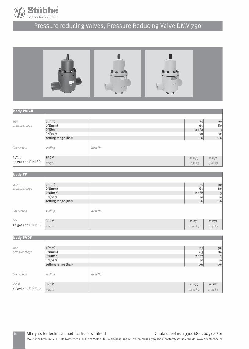
body PVC-U
9075d(mm)sizepressure range 8065DN(mm)
32 1/2DN(inch)1010PN(bar)
1-61-6setting range (bar)
ident No.sealingConnection
11117415.00 kg
11117312.50 kg
EPDMweight
PVC-Uspigot end DIN ISO
body PP
9075d(mm)sizepressure range 8065DN(mm)
32 1/2DN(inch)1010PN(bar)
1-61-6setting range (bar)
ident No.sealingConnection
11117713.50 kg
11117611.90 kg
EPDMweight
PPspigot end DIN ISO
body PVDF
9075d(mm)sizepressure range 8065DN(mm)
32 1/2DN(inch)1010PN(bar)
1-61-6setting range (bar)
ident No.sealingConnection
11118017.20 kg
11117914.10 kg
EPDMweight
PVDFspigot end DIN ISO
> data sheet no.: 330068 - 2009/01/01All rights for technical modifications withheld6ASV Stübbe GmbH & Co. KG · Hollwieser Str. 5 · D-32602 Vlotho · Tel. +49(0)5733. 799-0 · Fax +49(0)5733. 799-5000 · [email protected] · www.asv-stuebbe.de
Pressure reducing valves, Pressure Reducing Valve DMV 750
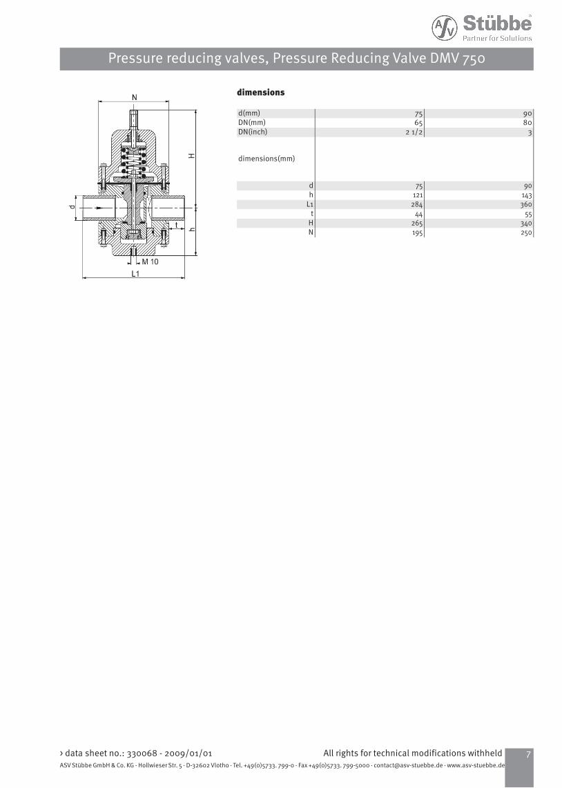
dimensions
9075d(mm)8065DN(mm)
32 1/2DN(inch)
dimensions(mm)
9075d143121h360284L1
5544t340265H250195N
7All rights for technical modifications withheld> data sheet no.: 330068 - 2009/01/01ASV Stübbe GmbH & Co. KG · Hollwieser Str. 5 · D-32602 Vlotho · Tel. +49(0)5733. 799-0 · Fax +49(0)5733. 799-5000 · [email protected] · www.asv-stuebbe.de
Pressure reducing valves, Pressure Reducing Valve DMV 750

Exploded viewDMV 750 DN 65
designationquantitypositionvalve body11bonnet12pressure spring13diaphragm14piston, complete15spring plate16pressure plate17adjustment screw18counter nut19cap110screw212hexagon nut113O-ring114Flange115O-ring117screw219threaded bolt820pressure gauge121flat sealing ring122pressure spring133
> data sheet no.: 330068 - 2009/01/01All rights for technical modifications withheld8ASV Stübbe GmbH & Co. KG · Hollwieser Str. 5 · D-32602 Vlotho · Tel. +49(0)5733. 799-0 · Fax +49(0)5733. 799-5000 · [email protected] · www.asv-stuebbe.de
Pressure reducing valves, Pressure Reducing Valve DMV 750
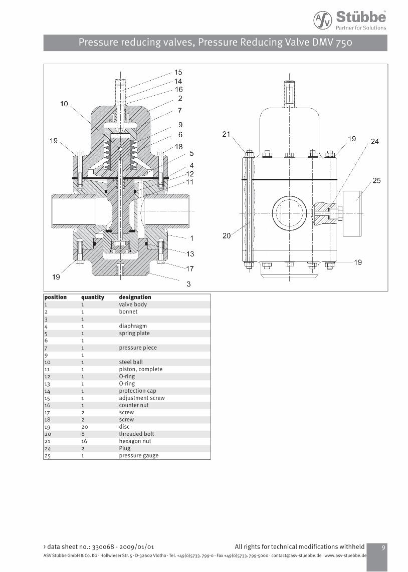
designationquantitypositionvalve body11bonnet12
13diaphragm14spring plate15
16pressure piece17
19steel ball110piston, complete111O-ring112O-ring113protection cap114adjustment screw115counter nut116screw217screw218disc2019threaded bolt820hexagon nut1621Plug224pressure gauge125
9All rights for technical modifications withheld> data sheet no.: 330068 - 2009/01/01ASV Stübbe GmbH & Co. KG · Hollwieser Str. 5 · D-32602 Vlotho · Tel. +49(0)5733. 799-0 · Fax +49(0)5733. 799-5000 · [email protected] · www.asv-stuebbe.de
Pressure reducing valves, Pressure Reducing Valve DMV 750

Characteristic curvesDN 80
pA = working pressureQ = flow
Configuration example
The valve is set tight at 4 bar.Desired flow rate 30000 l/h, Medium H²OAccording to the curve, this results in the following values:set pressure pE: 4 bar; Pressure reduction: p = 1,8 bar; Working pressure pA = ca. 2,2 barDN 80
pA = working pressureQ = flow
> data sheet no.: 330068 - 2009/01/01All rights for technical modifications withheld10ASV Stübbe GmbH & Co. KG · Hollwieser Str. 5 · D-32602 Vlotho · Tel. +49(0)5733. 799-0 · Fax +49(0)5733. 799-5000 · [email protected] · www.asv-stuebbe.de
Pressure reducing valves, Pressure Reducing Valve DMV 750