Embed Size (px)
Citation preview

EV 1S / AEV 1S
25www.condor-cpc.com
Pressure switch MDR 1
Order reference Type code ON / OFFRotary knob
Pressure rangePOFF in bar Flange Weight (in g) Part No.
MDR 1/6 MDR-1 DSD BAEA 017A030 XDE XXX - 2,5 - 6 1/4" ST 220 212119
MDR 1/6 MDR-1 DTD BAEA 017A030 XDE XXX - 2,5 - 6 1/4" ST-Ü 220 212126
Order reference Type code ON / OFFRotary knob
Pressure rangePOFF in bar Flange Weight (in g) Part No.
MDR1/11-EA MDR-1 GBA AAEA 060A080 QDE XXX EA 2,5 - 11 1/4" 220 212133
MDR1/11-EA MDR-1 GEA AAEA 060A080 QDE XXX EA 2,5 – 11 F4 1/4" 220 212140
MDR1/11-EA MDR-1 GFA AAEA 060A080 QDE XXX EA 2,5 – 11 F4 3/8“ 220 212157
MDR1/11 MDR-1 GBA BAEA 060A080 QDE XXX - 2,5 – 11 1/4" 220 216049
MDR1/11 MDR-1 GEA BAEA 060A080 QDE XXX - 2,5 – 11 F4 1/4" 220 216025
MDR1/11 MDR-1 GFA BAEA 060A080 QDE XXX - 2,5 - 11 F4 3/8“ 220 216063
Technical Data MDR 1
Rated insulation voltageUi
500 V
Motor switching capacity (AC 3)Ue=240 V (1~)
4,0 kW
Electrical life (AC 3) Cycles
> 1 x 10⁵
Mechanical life Cycles
> 5 x 10⁵
Max. electrical cycles Cycles/h
120
Max. mechanical cycles Cycles/h
600
Rated operational current Ie
at 240 V AC20 A
Bursting strength Pz > 35 bar
Permissible medium temperatureAir
- 5...+ 80 °C
Technical Data MDR 1 acc. to 60947 UL/CSA
Permissible medium temperatureWater
+ 70 °C
Degree of Protectionacc. to EN 60529
IP 44
Conductor cross-section 1 ..fine stranded cable 1 x / 2 x
2,5 / 2,5 mm2
Conductor cross-section 1rigid cable 1 x / 2 x
2,5 / 2,5 mm2
Diaphragm media resistance MDR 1
Acetylene, Butane, Ethylene glycol, Carbon dioxide, Air, Mineral oils, Water, Distilled water, Sea water, Hydrogen, Water steam
resistant
A detailed overview of diaphragm media resistance for all pressure switches can be found on page 22.
Pressure switch MDR 1 / 6, Pump version
Pressure switch MDR 1 / 11, Compressor version
Single phaseSwitching capacity 4.0 kWMax. cut-out pressure 6 barIncl. s PG 11 Z/ZK2-pole (N.C.) Steel flangeAcc. to EN 60947Optional differential adjustment
Single phase Switching capacity 4.0 kW Max. cut-out pressure 11 bar Incl. cable glands PG 11 Z/ZK and unloader valve AEV 1 S 2-pole (N.C.) Acc. to EN 60947 Optional differential adjustment
Hig
h pe
rfor
man
cePr
essu
re s
wit
ches

26
Pressure switch MDR 1
Order reference Description Weight (in g) Part No
Unloader valvesEV 1S* with quick-connect 6 mm for plastic unloader valves 25 226765
Delayed unloader valves AEV 1S* with quick-connect 6 mm for plastic unloader valves 25 217541
Cable glandsWN Grommet 6 200888
PG 11 G Conduits for mounting of cable glands (inner thread) 6 255024
PG 11 Z 12 255031
PG 11 ZK With strain relief and cable support 12 255048
CoverH1(Cover MDR 1)
Cover without On/Off lever (Neutral version, without marking) 40 230700
H1-EA (Cover MDR 1 + EA)
Cover with On/Off lever for manual On/Off (Neutral version, without marking) 40 227366
Cover MDR 1 + EA + lever
Conversion kit H1 to cover H1-EA 40 230717
Differential adjustmentMDR-1 Differential kit
Kit for setting cut-in and differential pressures (10 pcs.) 20 230618
Dimensions / Circuit Diagrams MDR 1
Unloader valves / Delayed unloader valves
Pressure switch MDR-1
*only for pneumatic tubes with outside tolerances according to e. g. Festo PAN 6x1mm
EV 1S / AEV 1SEV 1S AEV 1S
Accessories MDR 1
Dimensions unloader valves

2727www.condor-cpc.com
Pressure Diagrams MDR 1
Cable glands MDR 1
Pressure switch MDR 1
WN PG 11 G PG 11 Z PG 11 ZK
Explanation
Devices without differential pressure adjustmentAfter selecting the cut-in pressure, the cut-out pressure can be read from the pressure diagram. If only the cut-out pressure is known, the cut-in pressure to be set can also be determined from the diagram.
Example: MDR 1/6 without differential pressure adjustmentFor a preselected cut-in pressure of 4 bar, the cut-out pressure is 5 bar. If, for example, the cut-out pressure is to be 4 bar, a cut-in pressure of approx. 2.7 bar has to be set.
Devices with differential pressure adjustmentAn intersecting point is determined in the diagram by selecting a pair of cut-in and cut-out pressure values. If this point lies within theshaded area, this pair of values can be set on the pressure switch. If this point lies outside the shaded area, these values cannot be set.
Example: MDR 1/11 with differential pressure adjustmentWith a preselected cut-in pressure of 4 bar, the cut-out pressure can be determined and set between 5.4 and 8 bar using the differential pressure adjustment.
Hig
h pe
rfor
man
cePr
essu
re s
wit
ches

28
Pressure switch MDR 11
Order reference Type code ON / OFFRotary knob
Pressure rangePOFF in bar Flange Weight (in g) Part No.
MDR 11/6-EA MDR-11 DSD AAIA 017A030 XHI XXX EA 2,5 - 6 1/4" ST 300 235712
MDR 11/6-EA MDR-11 DTD AAIA 017A030 XHI XXX EA 2,5 - 6 1/4" ST-Ü 320 235729
Order reference Type code ON / OFFRotary knob
Pressure rangePOFF in bar Flange Weight (in g) Part No.
MDR 11/11-EA MDR-11 GBA AAIA 060A080 QHI XXX EA 2,5 - 11 1/4" 300 235736
MDR 11/11-EA MDR-11 GEA AAIA 060A080 QHI XXX EA 2,5 – 11 F4 1/4" 320 235743
Technical Data MDR 11 acc. to 60947 UL/CSA
Rated insulation voltageUi
500 V
Motor switching capacity (AC 3)Ue=240 V (1~)
4,0 kW
Motor switching capacity (UL 508, CSA 22.2) Ue=240 V (1~) / Ue=120 V (1~)
3,0 HP/2,0 HP
Electrical life (UL 508, CSA 22.2) Ue=240 V dc; 2,7A
0,5 HP
Electrical life (AC 3) Cycles
> 1 x 10⁵
Mechanical lifeCycles
> 5 x 10⁵
Max. electrical cycles Cycles/h
120
Max. mechanical cycles Cycles/h
600
Rated operational current Ie (EN 60947)at 240 V AC
20 A
Rated operational current Ie (UL/CSA)at 240 V AC
26 A
Bursting strength Pz > 35 bar
Technical Data MDR 11 acc. to 60947 UL/CSA
Permissible medium temperatureAir
- 5...+ 80 °C
Permissible medium temperatureWater
+ 70 °C
Degree of Protectionacc. to EN 60529
IP 44
Conductor cross-section 1 ..fine stranded cable 1 x / 2 x
2,5 / 2,5 mm2
Conductor cross-section 1rigid cable 1 x / 2 x 2,5 / 2,5 mm2
Diaphragm media resistance MDR 11
Acetylene, Butane, Ethylene glycol, Carbon dioxide, Air, Mineral oils, Water, Distilled water, Sea water, Hydrogen, Water steam
resistant
A detailed overview of diaphragm media resistance for all pressure switches can be found on page 22.
Pressure switch MDR 11 / 6, Pump version
Pressure switch MDR 11 / 11, Compressor version
Single phaseSwitching capacity 4.0 kW / 4 HpMax. cut-out pressure 6 bar / 87 psiIncl. cable glands PG13.5 Z/ZK2-pole (N.C.) Steel flange Acc. to EN 60947 UL / CSA-approval optionalOptional differential adjustment
Single phase Switching capacity 4.0 kW / 4 HP Max. cut-out pressure 11 bar / 160 psi Incl. cable glands PG13,5 Z/ZK With delayed unloader valve AEV 11 S 2-pole (N.C.) Acc. to EN 60947 UL / CSA-approval optional Optional differential adjustment
Cable glands for retrofitting, see accessories!
Unloader valves and cable glands for retrofitting, see accessories!
Steel flange ST-Ü

29www.condor-cpc.com
Pressure switch MDR 11
29
*only for pneumatic tubes with outside tolerances according to e. g. Festo PAN 6x1mm
Order reference Description Weight (in g) Part No.
Unloader valvesEV 1 S* with quick-connect 6 mm for plastic unloader valves 25 226765
EV 1 WSi 90° unloader valve with quick-connect for 1/4“ plastic tubes, quick-connect can be rotated 360° 25 247593
Delayed unloader valves AEV 1 S* with quick-connect 6 mm for plastic unloader valves 25 217541
Cable glandsWN Grommets 6 201243
PG 13,5 Z-21 With strain relief 12 201021
PG 13,5 ZK-21 With strain relief and cable support 12 201038
Differential pressure adjustmentMDR 1Differential kit
Kit for setting cut-in and differential pressures (10 pcs.) 20 230618
Dimensions / Circuit Diagrams MDR 11
Unloader valves / Delayed unloader valves
Cable glands MDR 11
Pressure switch MDR 11
EV 1S
WN
EV 1WSi AEV 1S
Accessories MDR 11
PG 13,5 Z-21 PG 13,5 ZK-21
Hig
h pe
rfor
man
cePr
essu
re s
wit
ches

30
Pressure switch MDR 11
Dimensions, Accessories MDR 11
Pressure Diagrams MDR 11
EV 1S / AEV 1S EV 1WSi
Explanation
Devices without differential pressure adjustmentAfter selecting the cut-in pressure, the cut-out pressure can be read from the pressure diagram. If only the cut-out pressure is known, the cut-in pressure to be set can also be determined from the diagram.
Example: MDR 1/6 without differential pressure adjustmentFor a preselected cut-in pressure of 4 bar, the cut-out pressure is 5 bar. If, for example, the cut-out pressure is to be 4 bar, a cut-in pressure of approx. 2.7 bar has to be set.
Devices with differential pressure adjustmentAn intersecting point is determined in the diagram by selecting a pair of cut-in and cut-out pressure values. If this point lies within thebshaded area, this pair of values can be set on the pressure switch. If this point lies outside the shaded area, these values cannot be set.
Example: MDR 1/11 with differential pressure adjustmentWith a preselected cut-in pressure of 4 bar, the cut-out pressure can be determined and set between 5.4 and 8 bar using the differential pressure adjustment.

31www.condor-cpc.com
Dimensions / Circuit Diagrams MDR 2
Pressure switch MDR 2
Pressure switch MDR-2
31
Order reference Type code ON / OFFRotary knob
Pressure rangePOFF in bar Flange Weight (in g) Part No.
MDR 2/6-EA MDR-2 DBA AAAA 015A030 XAA XXX EA 1,5 - 7 1/4" 300 212164
MDR 2/11-EA MDR-2 GBA AAAA 070A090 XAA XXX EA 4 - 12 1/4" 300 212171
MDR 2/11-EA MDR-2 GEA AAAA 070A090 XAA XXX EA 4 - 12 F4 1/4" 320 212188
MDR 2/11-EA MDR-2 GFA AAAA 070A090 XAA XXX EA 4 - 12 F4 3/8" 320 212195
MDR 2/11-EA MDR-2 GDA AAAA 070A090 XAA XXX EA 4 - 12 F4 1/2" 320 212201
MDR 2/6 MDR-2 DBA BAAA 015A030 XAA XXX - 1,5 - 7 1/4" 300 217381
MDR 2/11 MDR-2 GBA BAAA 070A090 XAA XXX - 4 - 12 1/4" 300 217404
MDR 2/11 MDR-2 GEA BAAA 070A090 XAA XXX - 4 - 12 F4 1/4" 320 219408
MDR 2/11 MDR-2 GFA BAAA 070A090 XAA XXX - 4 - 12 F4 3/8" 320 226888
MDR 2/11 MDR-2 GDA BAAA 070A090 XAA XXX - 4 - 12 F4 1/2" 320 226895
Technical Data MDR 2 acc. to 60947
Rated insulation voltageUi
500 V
Motor switching capacity (AC 3)Ue=240 V (1~)
2,2 kW
Electrical life (AC 3) Cycles
> 1 x 10⁵
Mechanical life Cycles
> 5 x 10⁵
Max. electrical cycles Cycles/h
120
Max. mechanical cycles Cycles/h
600
Rated operational current Ie
at 240 V AC 316 A
Bursting strength Pz > 35 bar
Permissible medium temperatureAir
- 5...+ 80 °C
Technical Data MDR 2 acc. to 60947
Permissible medium temperatureWater
+ 80 °C
Degree of Protectionacc. to EN 60529
IP 44
Conductor cross-section 1 ..fine stranded cable 1 x / 2 x
2,5 / 2,5 mm2
Conductor cross-section 1rigid cable 1 x / 2 x
2,5 / 2,5 mm2
Diaphragm media resistance MDR 2
Air, Water resistant
A detailed overview of diaphragm media resistance for all pressure switches can be found on page 22..
Pressure switch MDR 2
Single phase Switching capacity 2.2 kW Max. cut-out pressure 12 bar 2-pole (N.C.) Acc. to EN 60947
Unloader valves and cable glands for retrofitting, see accessories!
Hig
h pe
rfor
man
cePr
essu
re s
wit
ches

32
Pressure switch MDR 2
Order reference Description Weight (in g) Part No
Unloader valvesEV 2 With screw connection for 6 mm plastic or copper discharge tubes 25 200666
EV 2S* With quick-connect for 6 mm plastic discharge tubes 25 200680
EV 2W 90° with screw connection for 6 mm plastic or discharge copper tubes 25 200697
EV 2Wi 90° with screw connection for 1/4" mm plastic or discharge copper tubes 15 200703
EV 2WS* 90° with quick-connect for 6 mm plastic discharge tubes 15 200710
Delayed unloader valves AEV 2 With screw connection for 6 mm plastic or copper discharge tubes 25 200727
AEV 2S* With quick-connect for 6 mm plastic discharge tubes 25 200741
AEV 2W 90° with screw connection for 6 mm plastic or copper discharge tubes 15 200758
AEV 2Wi 90° with screw connection for 1/4" mm plastic or copper discharge tubes 15 200765
AEV 2WS* 90° with quick-connect for 6 mm plastic discharge tubes 15 200772
Cable glands
WN Grommet 6 200888
PG 11 G Conduits for mounting of cable glands (Inner thread) 6 200895
PG 11 V Cable gland complete 12 200901
PG 11 Z With strain relief 12 200925
PG 11 ZK With strain relief and cable support 12 200918
PG 13,5 G Conduits for mounting of cable glands (Inner thread) 6 200963
PG 13,5 V Cable gland complete 12 200932
PG 13,5 Z With strain relief 12 200956
PG 13,5 ZK With strain relief and cable support 12 200949
Cover
H2(Cover MDR 2)
Cover without On/Off lever (Neutral version without marking) 40 217510
H2-EA (Cover MDR 2+EA)
Cover with On/Off lever for manual On/Off (neutral version, without marking) 40 229445
Unloader valves / Delayed unloader valves
EV 2
EV 2W / EV 2Wi
EV 2S
AEV 2W / AEV 2Wi
AEV 2S
EV 2WS
AEV 2
AEV 2WS
Accessories MDR 2
*only for pneumatic tubes with outside tolerances according to e. g. Festo PAN 6x1mm
33www.condor-cpc.com
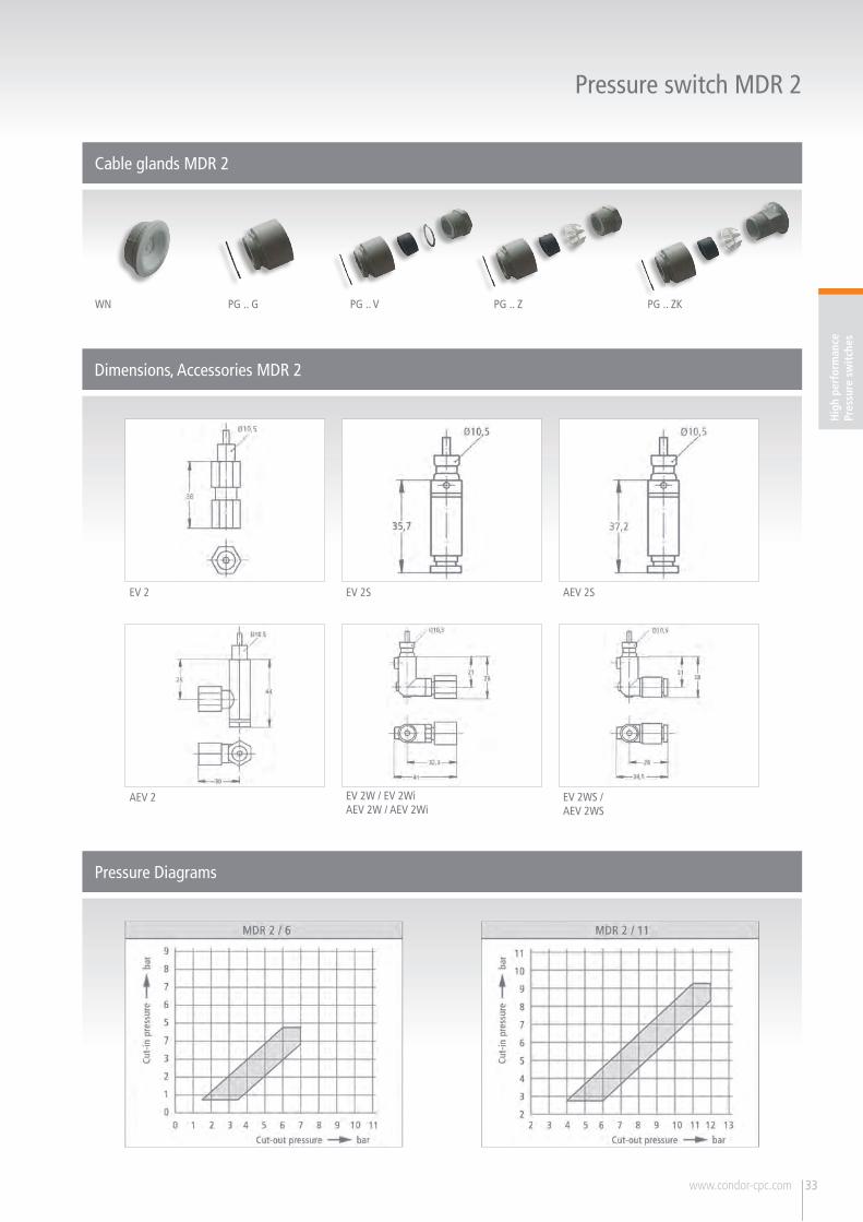
Dimensions, Accessories MDR 2
Pressure Diagrams
Cable glands MDR 2
Pressure switch MDR 2
WN PG .. G PG .. V PG .. ZKPG .. Z
33
EV 2
AEV 2
EV 2S
EV 2W / EV 2WiAEV 2W / AEV 2Wi
AEV 2S
EV 2WS /AEV 2WS
Hig
h pe
rfor
man
cePr
essu
re s
wit
ches

34
Pressure switch MDR 21
Technical Data MDR 21 nach EN 60947 UL/CSA
Rated insulation voltageUi
500 V
Motor switching capacity (UL 508, CSA 22.2)Ue=120 V (1~)
2 HP
Motor switching capacity (UL 508, CSA 22.2) Ue=240 V (1~)
3 HP
Motor switching capacity (AC 3) Cycles
2,2 kW
Electrical life (AC 3) Cycles
> 1 x 10⁵
Mechanical life Cycles
> 5 x 10⁶
Max. electrical cycles Cycles/h
120
Max. mechanical cycles Cycles/h
600
Rated operational current Ie (UL 508, CSA 22.2)at 240 V AC
24 A
Bursting strength Pz > 35 bar
Technical Data MDR 21 nach EN 60947 UL/CSA
Permissible medium temperatureAir
- 5...+ 80 °C
Permissible medium temperatureWater
+ 80 °C
Degree of Protectionacc. to EN 60529
IP 44
Conductor cross-section 1 …fine stranded cable 1 x / 2 x
2,5 / 2,5 mm2
Conductor cross-section 1 …rigid cable 1 x / 2 x 2,5 / 2,5 mm2
Diaphragm media resistance MDR 21
Air, Waterresistant
A detailed overview of diaphragm media resistance for all pressure switches can be found on page 22.
Pressure switch MDR 21
Single phaseSwitching capacity 2.2 kWMax. cut-out pressure 12 bar / 175 psi2-pole (N.C.)Acc. to EN 60947UL / CSA-approval optional
Unloader valves and cable glands for retrofitting, see accessories!
Order reference Type code ON / OFFRotary knob
Pressure rangePOFF in bar Flange Weight (in g) Part No.
MDR 21/6-EA MDR-21 DBA AACA 015A030 XAA XXX EA 1,5 - 7 1/4" 300 212218
MDR 21/6-EA MDR-21 DEA AACA 015A030 XAA XXX EA 1,5 - 7 F4 1/4" 320 212225
MDR 21/11-EA MDR-21 GBA AACA 070A090 XAA XXX EA 4 - 12 1/4" 300 212232
MDR 21/11-EA MDR-21 GEA AACA 070A090 XAA XXX EA 4 - 12 F4 1/4" 320 212249
MDR 21/6 MDR-21 DBA BACA 015A030 XAA XXX - 1,5 - 7 1/4" 300 219910
MDR 21/6 MDR-21 DEA BACA 015A030 XAA XXX - 1,5 - 7 F4 1/4" 320 226901
MDR 21/11 MDR-21 GBA BACA 070A090 XAA XXX - 4 - 12 1/4" 300 226918
MDR 21/11 MDR-21 GEA BACA 070A090 XAA XXX - 4 - 12 F4 1/4" 320 226925
Dimensions / Circuit Diagrams MDR 21
Pressure switch MDR 21

35www.condor-cpc.com
Pressure switch MDR 21
Order reference Description Weight (in g) Part No.
Unloader valvesEV 2 With screw connection for 6 mm plastic or copper discharge tubes 25 200666
EV 2S* With quick-connect for 6 mm plastic discharge tubes 25 200680
EV 2W 90° with screw connection for 6 mm plastic or discharge copper tubes 15 200697
EV 2Wi 90° with screw connection for 1/4" mm plastic or discharge copper tubes 15 200703
EV 2WS* 90° with quick-connect for 6 mm plastic discharge tubes 15 200710
Delayed unloader valvesAEV 2 With screw connection for 6 mm plastic or copper discharge tubes 25 200727
AEV 2S* With quick-connect for 6 mm plastic discharge tubes 25 200741
AEV 2W 90° with screw connection for 6 mm plastic or copper discharge tubes 15 200758
AEV 2Wi 90° with screw connection for 1/4" mm plastic or copper discharge tubes 15 200765
AEV 2WS* 90° with quick-connect for 6 mm plastic discharge tubes 15 200772
Cable glandsWN Grommet 6 201243
PG 13,5 Z-21 With strain relief 12 201021
PG 13,5 ZK-21 With strain relief and cable support 12 201038
CoverH 21(Cover MDR 21)
Cover without On/Off lever (Neural version without marking) 40 229452
H 21-EA (Cover MDR 2+EA)
Cover with On/Off lever for manual On/Off (neutral version, without marking) 40 217503
Unloader valves / Delayed unloader valves
EV 2
EV 2W / EV 2Wi
EV 2S
AEV 2W / AEV 2Wi
AEV 2S
EV 2WS
AEV 2
AEV 2WS
Accessories MDR 21
* only for pneumatic tubes with outside tolerances according to e. g. Festo PAN 6x1mm
Cable glands MDR 21
WN PG 13,5 Z-21 PG 13,5 ZK-21
Hig
h pe
rfor
man
cePr
essu
re s
wit
ches

36
Pressure switch MDR 21
Dimensions, Accessories MDR 21
Pressure Diagrams
EV 2
AEV 2
1 bar = 14,5 psi; 10 psi = ca. 0,7 bar
EV 2S
EV 2W / EV 2WiAEV 2W / AEV 2Wi
AEV 2S
EV 2WS /AEV 2WS