Embed Size (px)
Citation preview
Pressure Vessel Inspection Code:
In-service Inspection, Rating, Repair, and Alteration
API 510 TENTH ELEVENTH EDITION, MAY 2014 ADDENDUM 1, MAY 2017 ADDENDUM 2, MARCH 2018
Second BALLOT April 2019
The entire content of API 510 is open for review and comment, not just the tracked changes shown in the document Note to balloters: Please ignore formatting and numbering issues and focus on technical/editorial content. Formatting and numbering issues will be cleaned up before re-publication.. All proposed changes from the 10th edition are shown.
In order to properly organize the ballot resolution spreadsheet please be sure to enter the section numbers under the ballot spot labeled “clause/sub-clause number”; and then under “paragraph/table/figure number” simply indicate which paragraph in the section you are commenting upon. DO NOT put document section numbers in that column or your comments may be lost.
Please be sure to label comments “technical” only when a substantive change is being made and “editorial” when you are just suggesting some wording improvements. Comments labeled “general” should be those that apply to the multiple sections or the whole document.
When voting “Negative” please label the specific comments regarding your negative so we may be able to specific concern.
Special Notes
API publications necessarily address problems of a general nature. With respect to particular circumstances, local, state, and federal laws and regulations should be reviewed.
Neither API nor any of API's employees, subcontractors, consultants, committees, or other assignees make any warranty or representation, either express or implied, with respect to the accuracy, completeness, or usefulness of the information contained herein, or assume any liability or responsibility for any use, or the results of such use, of any information or process disclosed in this publication. Neither API nor any of API's employees, subcontractors, consultants, or other assignees represent that use of this publication would not infringe upon privately owned rights.
API publications may be used by anyone desiring to do so. Every effort has been made by the Institute to assure the accuracy and reliability of the data contained in them; however, the Institute makes no representation, warranty, or guarantee in connection with this publication and hereby expressly disclaims any liability or responsibility for loss or damage resulting from its use or for the violation of any authorities having jurisdiction with which this publication may conflict.
API publications are published to facilitate the broad availability of proven, sound engineering and operating practices. These publications are not intended to obviate the need for applying sound engineering judgment regarding when and where these publications should be utilized. The formulation and publication of API publications is not intended in any way to inhibit anyone from using any other practices.
Any manufacturer marking equipment or materials in conformance with the marking requirements of an API standard is solely responsible for complying with all the applicable requirements of that standard. API does not represent, warrant, or guarantee that such products do in fact conform to the applicable API standard.
Users of this Standard should not rely exclusively on the information contained in this document. Sound business, scientific, engineering, and safety judgment should be used in employing the information contained herein.
Work sites and equipment operations may differ. Users are solely responsible for assessing their specific equipment and premises in determining the appropriateness of applying the Standard. At all times users should employ sound business, scientific, engineering, and judgment safety when using this Standard.
All rights reserved. No part of this work may be reproduced, translated, stored in a retrieval system, or transmitted by any means, electronic, mechanical, photocopying, recording, or otherwise, without prior written permission from the publisher. Contact the
Publisher, API Publishing Services, 1220 L Street, NW, Washington, DC 20005.
Copyright © 2014 American Petroleum Institute
iii
Foreword
In December 1931, API and the American Society of Mechanical Engineers (ASME) created the Joint API/ASME Committee on Unfired Pressure Vessels. This committee was created to formulate and prepare for publication a code for safe practices in the design, construction, inspection, and repair of pressure vessels to be used in the petroleum industry. Entitled API/ASME Code for Unfired Pressure Vessels for Petroleum Liquids and Gases (commonly called the API/ASME Code for Unfired Pressure Vessels or API/ASME Code), the First Edition of the API/ASME Code was approved for publication in 1934. From its inception, the API/ASME Code contained Section I, which covered recommended practices for vessel inspection and repair and for establishing allowable working pressures for vessels in service. Section I recognized and afforded well-founded bases for handling various problems associated with the inspection and rating of vessels subject to corrosion. Although the provisions of Section I (like other parts of the API/ ASME Code) were originally intended for pressure vessels installed in the plants of the petroleum industry, especially those vessels containing petroleum gases and liquids, these provisions were actually considered to be applicable to pressure vessels in most services. ASME’s Boiler and Pressure Vessel Committee adopted substantially identical provisions and published them as a nonmandatory appendix in the 1950, 1952, 1956, and 1959 editions of Section VIII of the ASME Boiler and Pressure Vessel Code.
After the API/ASME Code was discontinued in 1956, a demand arose for the issuance of Section I as a separate publication, applicable not only to vessels built in accordance with any edition of the API/ASME Code but also to vessels built in accordance with any edition of Section VIII of the API/ASME Code. Such a publication appeared to be necessary to assure industry that the trend toward uniform maintenance and inspection practices afforded by Section I of the API/ASME Code would be preserved. API 510, first published in 1958, is intended to satisfy this need.
The procedures in Section I of the 1951 edition of the API/ASME Code, as amended by the March 16, 1954 addendum, have been updated and revised in API 510. Section I of the API/ASME Code contained references to certain design or construction provisions, so these references have been changed to refer to provisions in the API/ ASME Code. Since the release of the 1960 edition of the National Board Inspection Code, elements of the API/ASME Code have also been carried by the National Board Inspection Code.
It is the intent of API to keep this publication up to date. All pressure vessel owners and operators are invited to report their experiences in the inspection and repair of pressure vessels whenever such experiences may suggest a need for revising or expanding the practices set forth in API 510.
This edition of API 510 supersedes all previous editions of API 510. Each edition, revision, or addendum to this API code may be used beginning with the date of issuance shown on the cover page for that edition, revision, or addendum. Each edition, revision, or addendum to this API code becomes effective six months after the date of issuance for equipment that is rerated, reconstructed, relocated, repaired, modified (altered), inspected, and tested per this code. During the six-month time between the date of issuance of the edition, revision, or addendum and the effective date, the user shall specify to which edition, revision, or addendum the equipment is to be rerated, reconstructed, relocated, repaired, modified (altered), inspected, and tested.
Nothing contained in any API publication is to be construed as granting any right, by implication or otherwise, for the manufacture, sale, or use of any method, apparatus, or product covered by letters patent. Neither should anything contained in the publication be construed as insuring anyone against liability for infringement of letters patent.
Shall: As used in a standard, “shall” denotes a minimum requirement in order to conform to the specification.
Should: As used in a standard, “should” denotes a recommendation or that which is advised but not required in order to conform to the specification.
This document was produced under API standardization procedures that ensure appropriate notification and participation in the developmental process and is designated as an API standard. Questions concerning the interpretation of the content of this publication or comments and questions concerning the procedures under which
iv
this publication was developed should be directed in writing to the Director of Standards, American Petroleum Institute, 1220 L Street, NW, Washington, DC 20005. Requests for permission to reproduce or translate all or any part of the material published herein should also be addressed to the Director.
Generally, API standards are reviewed and revised, reaffirmed, or withdrawn at least every five years. A one-time extension of up to two years may be added to this review cycle. Status of the publication can be ascertained from the API Standards Department, telephone (202) 682-8000. A catalog of API publications and materials is published annually by API, 1220 L Street, NW, Washington, DC 20005.
Suggested revisions are invited and should be submitted to the Standards Department, API, 1220 L Street, NW, Washington, DC 20005, [email protected].
v
Contents
1. Scope 1 1.1. General Application 1 1.2. Specific Applications 2
2. Normative References 3
3. Terms, Definitions, Acronyms, and Abbreviations 4 3.1. Terms and Definitions 4 3.2. Acronyms and Abbreviations 14
4. Owner/User Inspections Organization 15 4.1. Owner/User Organization Responsibilities 15 4.2. Engineer 18 4.3. Repair Organization 18 4.4. Inspector 18 4.5. Examiners 18 4.6. Other Personnel 18 4.7. Inspection Organization Audits 19
5. Inspection, Examination, and Pressure Testing Practices 19 5.1. Inspection Plans 19 5.2. Risk-Based Inspection (RBI) 21 5.3. Preparation for Inspection 22 5.4. Inspection for Different Types of Damage Mechanisms and Failure Modes 23 5.5. Types of Inspection and Surveillance for Pressure Vessels 26 5.6. Condition Monitoring Locations (CML) 31 5.7. Condition Monitoring Methods 32 5.8. Pressure Testing 34 5.9. Material Verification and Traceability 36 5.10. Inspection of In-service Welds 37 5.11. Inspection and Repair of Flanged Joints 37 5.12. Inspection of Shell and Tube Heat Exchangers 38
6. Interval/Frequency and Extent of Inspection 38 6.1. General 38 6.2. Inspection During Installation and Service Changes 38 6.3. RBI 39 6.4. External Inspection 39 6.5. Internal, On-stream, and Thickness Measurement Inspections 40 6.6. Pressure-relieving Devices 42 6.7. Deferral of Inspections, Tests and Examinations 43 6.8. Deferral of Inspection Repair Recommendation Due Dates 44 6.9. Review of Inspection Repair Recommendations 45
7. Inspection Data Evaluation, Analysis, and Recording 45 7.1. Corrosion Rate Determination 45 7.2. Remaining Life Calculations 46 7.3. Maximum Allowable Working Pressure (MAWP) Determination 47 7.4. Analysis of Corroded Regions 47 7.5. FFS Evaluations 50 7.6. Required Thickness Determination 51 7.7. Evaluation of Existing Equipment with Minimal Documentation 51
vi
7.8. Reports and Records 52
8. Repairs, Alterations, and Rerating of Pressure Vessels and Pressure-relieving Devices 53 8.1. Repairs and Alterations 53 8.2. Temporary Repairs 54 8.3. Permanent Repair 56 8.4. Welding and Hot Tapping 58 8.5. Postweld Heat Treatment (PWHT) 59 8.6. Preheat or Controlled-deposition Welding (CDW) Methods as Alternatives to PWHT 59 8.7. NDE of Welds 62 8.8. Rerating 62
9. Alternative Rules for E&P Pressure Vessels 65 9.1. Scope and Specific Exemptions 65 9.2. Definitions 65 9.3. Inspection Program 66 9.4. Pressure Test 70 9.5. Safety Relief Devices 70 9.6. Records 70
Annex A (normative) Code Exemptions 71
Annex B (normative) Inspector Certification 73
Annex C (informative) Sample Pressure Vessel Inspection Record 75
Annex D (informative) Sample Repair, Alteration, or Rerating of Pressure Vessel Form 77
Annex E (informative) Technical Inquiries 79
Figures 8.1 Rerating Vessels Using the Latest Edition or Addendum of the ASME Code Allowable Stresses ... 64 8.2 Sample Additional Nameplate .................................................................................................................... 65
Tables 7.1 Values of Spherical Radius Factor K1 ........................................................................................................... 50 8.1 Qualification Limits for Base Metal and Weld Deposit Thicknesses for the CDW Method ............................ 61
1
Pressure Vessel Inspection Code: In-service Inspection, Rating, Repair, and Alteration
1. Scope
1.1. General Application
1.1.1. Coverage
This inspection code covers the in-service inspection, repair, alteration, and rerating activities for pressure vessels and the pressure-relieving devices protecting these vessels. This inspection code applies to all hydrocarbon and chemical process vessels that have been placed in servicein-service unless specifically excluded per Section 1.2.2; but it could also be applied to process vessels in other industries at owner/user discretion. This includes:
a) vessels constructed in accordance with an applicable construction code [e.g. ASME Boiler and Pressure Vessel Code (ASME Code)];
b) vessels constructed without a construction code (noncode vessels)—a vessel not fabricated to a recognized construction code and meeting no known recognized standard;
c) vessels constructed and approved as jurisdictional special based upon jurisdiction acceptance of particular design, fabrication, inspection, testing, and installation;
d) nonstandard vessels—a vessel fabricated to a recognized construction code but has lost its nameplate or stamping.
However, vessels that have been officially retired from service and abandoned in placedecommissioned (i.e. no longer are an asset of record from a financial/accounting standpoint) are no longer covered by this “in-service inspection” code.
The ASME Code and other recognized construction codes are written for new construction; however, most of the technical requirements for design, welding, Non-Destructive Examination (NDE), and materials can be applied to the inspection, rerating, repair, and alteration of in-service pressure vessels. If for some reason an item that has been placed in servicein-service cannot follow the construction code because of its new construction orientation, the requirements for design, material, fabrication, and inspection shall conform to API 510 rather than to the construction code. If in-service vessels are covered by requirements in the construction code and API 510 or if there is a conflict between the two codes, the requirements of API 510 shall take precedence. As an example of the intent of API 510, the phrase “applicable requirements of the construction code” has been used in API 510 instead of the phrase “in accordance with the construction code.”
1.1.2. Intent
The application of this inspection code is restricted to owner/users that employ or have access to the following technically qualified individuals and organizations:
a) an authorized inspection agency,
b) a repair organization,
c) an engineer,
d) an inspector, and,
PRESSURE VESSEL INSPECTION CODE: IN-SERVICE INSPECTION, RATING, REPAIR, AND ALTERATION 2
e) examiners.
Inspectors are to be certified as stated in this inspection code (see Annex B). Since other codes covering specific industries and general service applications already exist (e.g. NB-23), the refining and petrochemical industry has developed this inspection code to fulfill their own specific requirements for vessels and pressure-relieving devices that fit within the restrictions listed in the scope.
The intent of this code is to specify the in-service inspection and condition-monitoring program that is needed to determine the integrity of pressure vessels and pressure-relieving devices. The program should provide reasonably accurate and timely assessments to determine if any changes in the condition of pressure equipment could compromise continued safe operation. The owner/users shall respond to any inspection results that require corrective actions to assure the continued safe operation of pressure vessels and pressure-relieving devices.
This code does not cover source inspection of newly fabricated pressure vessels. Refer to RP588 Recommended Practice for Source Inspection and Quality Surveillance of Fixed Equipment for guidance on the surveillance of supplier vendors fabricating and/or repairing pressure vessels that will be installed on site. Owner/users may engage the services of individuals qualified per API RP 588 and who have become certified in the API ICP as Source Inspectors.
1.1.3. Limitations
Adoption and use of this inspection code does not permit its use in conflict with any prevailing regulatory requirements. However, if the requirements of this code are more stringent than the requirements of the regulation, then the requirements of this code shall govern.
1.2. Specific Applications
1.2.1. Exploration and Production (E&P) Vessels
All pressure vessels used for E&P service [e.g. drilling, producing, gathering, transporting, lease processing, and treating liquid petroleum, natural gas, and associated salt water (brine)] may be inspected under the alternative rules set forth in Section 9. Except for Section 6, all of the sections in this inspection code are applicable to pressure vessels in E&P service. The alternative rules in Section 9 are intended for services that may be regulated under safety, spill, emission, or transportation controls by the U.S. Coast Guard; the Office of Hazardous Materials Transportation of the U.S. Department of Transportation (DOT) and other units of DOT; the Bureau of Ocean Energy Management, Regulation, and Enforcement, formerly the Minerals Management Service of the U.S. Department of the Interior; state and local oil and gas agencies; or any other regulatory commission.
1.2.2. Excluded and Optional Services
Vessels excluded from the specific requirements of this inspection code are listed in Annex A. However, each owner/ user has the option of including any excluded pressure vessel in their inspection program as outlined in this code.
Some vessels exempted in accordance with the criteria in ASME Code, Section VIII, Division 1 should be considered for inclusion based on risk (probability and consequence of failure) as determined by the owner/user. An example of such vessels might be vacuum flashers in refining service or other large vessels operating in vacuum service.
1.2.3. Recognized Technical Concepts
For inspection planning and engineering assessment of in-service pressure vessels, this inspection code recognizes the applicability of Fitness-For-Service (FFS) assessment and risk-based inspection (RBI) methodologies. API 579-1/ ASME FFS-1 provides detailed assessment procedures for specific types of damage that are referenced in this code. API 580 provides guidelines for conducting a risk-based assessment program. API RP 581 provides a method of conducting RBI in accordance with the principles in API 580.
PRESSURE VESSEL INSPECTION CODE: IN-SERVICE INSPECTION, RATING, REPAIR, AND ALTERATION 3
2. Normative References
The following referenced documents are indispensable for the application of this document. For dated references, only the edition cited applies. For undated references, the latest edition of the referenced document (including any amendments) applies. The following documents are referred to in the text in such a way that some or all of their content constitutes requirements of this document. For dated references, only the edition cited applies. For undated references, the latest edition of the referenced document (including any addenda) applies.
API 510 Inspector Certification Examination Body of Knowledge
API Recommended Practice 571, Damage Mechanisms Affecting Fixed Equipment in the Refining Industry
API Recommended Practice 572, Inspection of Pressure Vessels
API Recommended Practice 576, Inspection of Pressure-relieving Devices
API Recommended Practice 577, Welding Inspection and Metallurgy
API Recommended Practice 578, Material Verification Program for New and Existing Alloy Piping Systems
API Standard 579-1/ASME FFS-1, Fitness-For-Service
API Recommended Practice 580, Risk-Based Inspection
API Recommended Practice 581, Risk-Based Inspection Methodology
API Recommended Practice 582, Welding Guidelines for the Chemical, Oil, and Gas Industries
API Recommended Practice 583, Corrosion Under Insulation and Fireproofing
API Recommended Practice 584, Integrity Operating Windows
API Recommended Practice 585, Pressure Equipment Integrity Incident Investigations
API Recommended Practice 751; Safe Operation of Hydrofluoric Acid Alkylation Units
API Recommended Practice 939-C, Guidelines for Avoiding Sulfidation (Sulfidic) Corrosion Failures in Oil Refineries
API Recommended Practice 941, Steels for Hydrogen Service at Elevated Temperatures and Pressures in Petroleum Refineries and Petrochemical Plants
API Recommended Practice 2201, Safe Hot Tapping Practices for the Petroleum and Petrochemical Industries
ASME PCC-11, Guidelines for Pressure Boundary Bolted Flange Joint Assembly
ASME PCC-2, Repair of Pressure Equipment and Piping
ASME Boiler and Pressure Vessel Code, Section II: Materials
ASME Boiler and Pressure Vessel Code, Section V: Nondestructive Examination
ASME Boiler and Pressure Vessel Code, Section VIII: Rules for Construction of Pressure Vessels; Division 1
1 ASME International, 3 Park Avenue, New York, New York 10016-5990, www.asme.org.
PRESSURE VESSEL INSPECTION CODE: IN-SERVICE INSPECTION, RATING, REPAIR, AND ALTERATION 4
ASME Boiler and Pressure Vessel Code, Section VIII: Rules for Construction of Pressure Vessels; Division 2: Alternative Rules
ASME Boiler and Pressure Vessel Code, Section IX: Welding and Brazing Qualifications
ASNT CP-1892, Standard for Qualification and Certification of Nondestructive Testing Personnel
ASNT SNT-TC-1A, Personnel Qualification and Certification in Nondestructive Testing
NACE MR01033, Materials Resistant to Sulfide Stress Cracking in Corrosive Petroleum Refining Environments
NACE SP0170, Protection of Austenitic Stainless Steels and Other Austenitic Alloys from Polythionic Acid Stress Corrosion Cracking During Shutdown of Refinery Equipment
NACE SP0472, Methods and Controls to Prevent In-service Environmental Cracking of Carbon Steel Weldments in Corrosive Petroleum Refining Environments
National Board NB-234, National Board Inspection Code
OSHA 29 CFR Part 19105, Occupational Safety and Health Standards
WRC Bulletin 4126, Challenges and Solutions in Repair Welding for Power and Processing Plants
3. Terms, Definitions, Acronyms, and Abbreviations
3.1. Terms and Definitions
For the purposes of this code, the following terms and definitions apply.
3.1.#
abandoned-in-place A pressure vessel thereof meeting all of the following: has been decommissioned with no intention for future use; has been completely de-inventoried/purged of hydrocarbon/chemicals; and is physically disconnected (e.g. air-gapped) from all energy sources and/or other piping/equipment.
3.1.1.
alteration A physical change in any component that has design implications that affect the pressure-containing capability of a pressure vessel beyond the scope described in existing data reports. The following should not be considered alterations: any comparable or duplicate replacement, the addition of any reinforced nozzle less than or equal to the size of existing reinforced nozzles, and the addition of nozzles not requiring reinforcement.
2 American Society for Nondestructive Testing, 1711 Arlingate Lane, P.O. Box 28518, Columbus, Ohio 43228, www.asnt.org. 3 NACE International (formerly the National Association of Corrosion Engineers), 1440 South Creek Drive, Houston, Texas 77218-8340, www.nace.org. 4 The National Board of Boiler and Pressure Vessel Inspectors, 1055 Crupper Avenue, Columbus, Ohio 43229, www.nationalboard.org. 5 Occupational Safety and Health Administration, 200 Constitution Avenue, NW, Washington, DC 20210, www.osha.gov. 6 Welding Research Council, P.O. Box 201547, Shaker Heights, Ohio 44120, www.forengineers.org.
PRESSURE VESSEL INSPECTION CODE: IN-SERVICE INSPECTION, RATING, REPAIR, AND ALTERATION 5
3.1.2.
applicable construction code The code, code section, or other recognized and generally accepted engineering standard or practice to which the pressure vessel was built or that is deemed by the owner/user or the engineer to be most appropriate for the situation.
3.1.3.
authorization Approval/agreement to perform a specific activity (e.g. repair) prior to the activity being performed.
3.1.4.
authorized inspection agency Any one of the following:
a) the inspection organization of the jurisdiction in which the pressure vessel is used;
b) the inspection organization of an insurance company that is licensed or registered to write and does write pressure vessel insurance;
c) the inspection organization of an owner/user owner or user of pressure vessels who maintains an inspection organization for his/her equipment only and not for vessels intended for sale or resale; or
d) an independent organization or individual that is under contract to and under the direction of an owner/user and that is recognized or otherwise not prohibited by the jurisdiction in which the pressure vessel is used. The owner/ user’s inspection program shall provide the controls that are necessary when contract inspectors are used.
3.1.5.
authorized pressure vessel inspector An employee of an authorized inspection agency who is qualified and certified to perform inspections under this inspection code, including Annex B. Whenever the term “inspector” is used in API 510, it refers to an authorized pressure vessel inspector.
3.1.6.
condition monitoring locations
CMLs Designated areas on pressure vessels where periodic external examinations are conducted in order to directly assess and monitor the condition of the vessel using a variety of examination methods and techniques based on the predicted damage mechanism(s). CMLs may contain one or more examination points and utilize multiple inspection techniques that are based on the predicted damage mechanism to give the highest probability of detection. CMLs can be a single small area on a pressure vessel (e.g. a 2-in. diameter spot) or plane through a section of a nozzle where recording points exist in all four quadrants of the plane).
NOTE CMLs now include but are not limited to what were previously called TMLs.
3.1.7.
construction code The code or standard to which a vessel was originally built, such as API/ASME (now out of date), ASME Code, API, or state special/non-ASME or any other construction code to which the vessel was built.
PRESSURE VESSEL INSPECTION CODE: IN-SERVICE INSPECTION, RATING, REPAIR, AND ALTERATION 6
3.1.8.
controlled-deposition welding
CDW Any welding technique used to obtain controlled grain refinement and tempering of the underlying heat-affected zone in the base metal. Various controlled-deposition techniques, such as temper bead (tempering of the layer below the current bead being deposited) and half bead (requiring removal of one-half of the first layer), are included. See 8.6
3.1.9.
corrosion allowance Additional material thickness available to allow for metal loss during the service life of the vessel component.
3.1.10.
corrosion rate The rate of metal loss due to erosion, erosion/corrosion, and/or the chemical reaction(s) with the environment, either internal and/or external.
3.1.11.
corrosion specialist A person, acceptable to the owner/user, who has knowledge of and experience in with corrosion damage mechanisms, metallurgy, materials selection, and corrosion monitoring techniques.
3.1.12.
corrosion under insulation
CUI Refers to all forms of CUI including chloride stress corrosion cracking and corrosion under fireproofing.
3.1.13.
cyclic service Refers to service conditions that may result in cyclic loading and produce fatigue damage or failure (e.g. cyclic loading from pressure, thermal, and/or mechanical loads).Refers to service conditions that may produce fatigue damage due to cyclic loading from pressure, thermal, and mechanical loads that are not induced by pressure. Other cyclic loads associated with vibration may arise from such sources as impact, turbulent flow vortices, resonance in compressors, and wind, or any combination thereof. See 5.4.4. Some examples of vessels in cyclic service include coke drums, mole sieves, and pressure swing adsorbers.
3.1.14.
damage mechanism Any type of deterioration encountered in the refining and chemical process industry that can result in flaws/defects that can affect the integrity of vessels (e.g. corrosion, cracking, erosion, dents, and other mechanical, physical, or chemical impacts). See API 571 for a comprehensive list and description of damage mechanisms.
3.1.#
decommissioned The end of the pressure vessel life-cycle. A pressure vessel at this stage of its life-cycle is either demolished or abandoned-in-place.
3.1.15.
defect An imperfection whose type or size exceeds the applicable acceptance criteria and is therefore rejectable.
PRESSURE VESSEL INSPECTION CODE: IN-SERVICE INSPECTION, RATING, REPAIR, AND ALTERATION 7
3.1.16.
deferral An approved and documented postponement of an inspection, test, or examination. See 6.6.3.4.
3.1.17.
design temperature The temperature used for the design of the pressure vessel per the applicable construction code.
3.1.18.
documentation Records containing descriptions of specific vessel design, personnel training, inspection plans, inspection results, NDE, repair, alteration, rerating and pressure testing activities, FFS assessments, procedures for undertaking these activities, or any other information pertinent to maintaining the integrity and reliability of vessels.
3.1.19.
due date The date established by the owner/userowner-user and in accordance with this code, whereby an inspection, test, examination, or inspection recommendation falls due or is to be completed. The date may be established by rule-based inspection methodologies (e.g. fixed intervals, retirement half-life interval, retirement date), risk-based methodologies (e.g. RBI target date), fitness-for-service analysis results, owner/userowner-user inspection agency practices/procedures/guidelines, or any combination thereof.
3.1.20.
engineer Pressure vessel engineer.
3.1.21.
examination point
recording point
measurement point
test point [test point is a term no longer in use as test refers to mechanical or physical tests (e.g. tensile tests or pressure tests)] A circular area having a maximum diameter of 3 in. (75mm) for pressure vessels and is located within a CML.An area within a CML defined by a circle having a diameter not greater than 3 in. (75 mm) for pressure vessels. CMLs may contain multiple examination points, for example, a vessel nozzle may be a CML and have multiple examination points (e.g. an examination point in all four quadrants of the CML on the nozzle).
3.1.22.
examinations A process by which an examiner investigates a component of the pressure vessel using NDE in accordance with approved NDE procedures (e.g. inspection of a CML, quality control (QC) of repair areas).Quality control (QC) functions performed by examiners (e.g. NDEs in accordance with approved NDE procedures).
3.1.23.
examiner A person who assists the inspector by performing specific NDE on pressure vessel components and evaluates to the applicable acceptance criteria but does not evaluate the results of those examinations in accordance with API 510, unless specifically trained and authorized to do so by the owner/user.
PRESSURE VESSEL INSPECTION CODE: IN-SERVICE INSPECTION, RATING, REPAIR, AND ALTERATION 8
3.1.24.
external inspection A visual inspection performed from the outside of a pressure vessel to find conditions that could impact the vessel’s ability to maintain pressure integrity or conditions that compromise the integrity of the supporting structures (e.g. ladders, platforms, supports). The external inspection may be done either while the vessel is operating or while the vessel is out-of-service and can be conducted at the same time as an on-stream inspection.
3.1.25.
Fitness-For-Service (FFS) evaluation A methodology whereby flaws and other deterioration/damage or operating conditions contained within a pressure vessel are assessed in order to determine the integrity of the vessel for continued service.
3.1.26.
general corrosion Corrosion that is distributed more or less uniformly over the surface of the metal, as opposed to localized corrosion.
3.1.27.
heat-affected zone The portion of the base metal whose mechanical properties or microstructure have been altered by the heat of welding or thermal cutting.
3.1.28.
hold point A point in the repair or alteration process beyond which work may not proceed until the required inspection or NDE has been performed.
3.1.#
Idle Pressure vessel not currently operating, but remains connected to piping, electrical or instrumentation (may be blinded or blocked in).
NOTE An idled pressure vessel is considered in-service and is still subject to the requirements of this code.
3.1.29.
imperfections Flaws or other discontinuities noted during inspection or examination that may or may not exceed the applicable acceptance criteria.
3.1.30.
indications A response or evidence resulting from the application of a NDE that may be nonrelevant or could be, flaws or defects upon further analysis.
3.1.31.
industry-qualified ultrasonic angle beam examiner A person who possesses an ultrasonic (UT) angle beam qualification from API (e.g. API QUTE/QUSE Detection and Sizing Tests) or an equivalent qualification approved by the owner/user.
NOTE Rules for equivalency are defined on the API ICP website.
PRESSURE VESSEL INSPECTION CODE: IN-SERVICE INSPECTION, RATING, REPAIR, AND ALTERATION 9
3.1.32.
In- service Designates a pressure vessel that has been placed in operation as opposed to new construction prior to being placed in service or retired vessels. A pressure vessel not in operation because of a process outage is still considered an in-service pressure vessel.
NOTE Does not include pressure vessels that are still under construction or in transport to the site prior to being placed in service or pressure vessels that have been retired from service. It does include pressure vessels that are temporarily out of service but still in place in an operating site. A stage in the service life of a vessel between installation and being removed from service.
The life-cycle stage of a pressure vessel that commences after installation, but before decommissioning. A pressure vessel not currently in operation because of a process outage, is still considered an in-service pressure vessel. It does include pressure vessels that are temporarily out of service but still in place in an operating site.
NOTE Does not include pressure vessels that are still under construction or in transport to a site prior to being placed in operation, nor does it include pressure vessels that have been decommissioned.
3.1.33.
in-service inspection All inspection activities associated with a in-service pressure vessel (after installation, but before it is decommissioned)once it has been placed in service but before it is permanently retired from service.
3.1.34.
inspection The external, internal, or on-stream evaluation (or any combination of the three) of the condition of a vessel conducted by the authorized inspector or his/her designee in accordance with this code.
3.1.35.
inspection code A reference to the API 510 code.
3.1.36.
inspection plan A strategy defining how and when a pressure vessel or pressure-relieving device will be inspected, examined, repaired, and/or maintained. See 5.1.
3.1.37.
inspector A shortened title for an authorized pressure vessel inspector qualified and certified in accordance with this code.
3.1.38.
integrity operating window
IOW Established limits for process variables (parameters) that can affect the integrity of the equipment if the process operation deviates from the established limits for a predetermined amount of time. See 4.1.4.
3.1.39.
internal inspection An inspection performed from the inside of a pressure vessel using visual and/or NDE techniques.
PRESSURE VESSEL INSPECTION CODE: IN-SERVICE INSPECTION, RATING, REPAIR, AND ALTERATION 10
3.1.40.
jurisdiction A legally constituted governmental administration that may adopt rules relating to pressure vessels.
3.1.41.
localized corrosion Corrosion that is largely typically confined to a limited or isolated area(s) of the metal surface of a pressure vessel.
3.1.42.
major repair Any work not considered an alteration that removes and replaces a major part of the pressure boundary other than a nozzle (e.g. replacing part of the shell or replacing a vessel head). If any of the restorative work results in a change to the design temperature, minimum allowable temperature (MAT), or maximum allowable working pressure (MAWP), the work shall be considered an alteration and the requirements for rerating shall be satisfied.
3.1.43.
management of change
MOC A documented management system for review and approval of changes (both physical and process) to pressure vessels prior to implementation of the change. The MOC process includes involvement of inspection personnel that may need to alter inspection plans as a result of the change.
3.1.44.
manufacturer’s data report A document that contains data and information from the manufacturer of the pressure vessel that certifies that the materials of construction contained in the vessel meet certain material property requirements, tolerances, etc. and are in accordance with specified standards.
3.1.45.
maximum allowable working pressure
MAWP The maximum gauge pressure permitted at the top of a pressure vessel in its operating position for a designated temperature. This pressure is based on calculations using the minimum (or average pitted) thickness for all critical vessel elements, (exclusive of thickness designated for corrosion) and adjusted for applicable static head pressure and nonpressure loads (e.g. wind, earthquake, etc.). The MAWP may refer to either the original design or a rerated MAWP obtained through a FFS assessment.
3.1.46.
minimum design metal temperature/minimum allowable temperature
MDMT/MAT The lowest permissible metal temperature for a given material at a specified thickness based on its resistance to brittle fracture. In the case of MAT, it may be a single temperature, or an envelope of allowable operating temperatures as a function of pressure. It is generally the minimum temperature at which a significant load can be applied to a pressure vessel as defined in the applicable construction code [e.g. ASME Code, Section VIII, Division 1, Paragraph UG-20(b)]. It might be also obtained through a FFS evaluation.
3.1.47.
nonpressure boundary Components of the vessel that do not contain the process pressure (e.g. trays, tray rings, distribution piping, baffles, nonstiffening insulation support rings, clips, davits, etc.).
PRESSURE VESSEL INSPECTION CODE: IN-SERVICE INSPECTION, RATING, REPAIR, AND ALTERATION 11
3.1.48.
on-stream A condition where a pressure vessel has not been prepared for an internal inspection. See on-stream inspection.
3.1.49.
on-stream inspection An inspection performed from the outside of a pressure vessel while it is on-stream using NDE procedures to establish the suitability of the pressure boundary for continued operation.
3.1.50.
overdue inspections Inspections for in-service vessels that are still in operation that have not been performed by their due dates documented in the inspection plan, which have not been deferred by a documented deferral process. See 6.6.3.4.
3.1.51.
overdue inspection recommendations Recommendations for repair or other mechanical integrity purposes for vessels that are still in operation that have not been completed by their documented due dates, which have not been deferred by a documented deferral process. See 6.8.
3.1.52.
owner/user An owner or user of pressure vessels who exercises control over the operation, engineering, inspection, repair, alteration, maintenance, pressure testing, and rerating of those pressure vessels.
3.1.53.
plate lining Metal plates that are welded to the inside of the pressure vessel wall for the purpose of protecting the vessel construction material from interaction with process fluids. Normally, plates are of a more corrosion resistant or erosion resistant alloy than the vessel wall and provide additional corrosion/erosion resistance. In some instances, plates of a material of construction similar to the vessel wall are used for specific operating periods where corrosion and/or erosion rates are predictable.
3.1.54.
postweld heat treatment
PWHT Treatment that consists of heating an entire weldment or vessel to a specified elevated temperature after completion of welding in order to relieve the detrimental effects of welding heat, such as to reduce residual stresses, reduce hardness, stabilize chemistry and/or slightly modify properties.
3.1.55.
pressure boundary That portion of the pressure vessel that contains the pressure retaining elements joined or assembled into a pressure tight, fluid-containing vessel (e.g. typically the shell, heads, and nozzles) but excluding nonpressure boundary items (e.g. such as supports, skirts, clips, etc. that do not retain pressure).
3.1.56.
pressure test A test performed on pressure vessels that have been in service and that have undergone an alteration or repair to the pressure boundary(s) to indicate that the integrity of the pressure components are still compliant with the original construction code. The pressure test can be hydrostatic, pneumatic, or a combination thereof. Pressure tests at
PRESSURE VESSEL INSPECTION CODE: IN-SERVICE INSPECTION, RATING, REPAIR, AND ALTERATION 12
pressures less than those specified by the construction code to determine if there may be leaks in the system are generally referred to as tightness tests.
3.1.57.
pressure vessel A container designed to withstand internal and/or external pressure. This pressure may be imposed by an external source, by the application of heat from a direct or indirect source, or by any combination thereof. This definition includes heat exchangers, air coolers, columns, towers, unfired steam generators (boilers), and other vapor generating vessels that use heat from the operation of a processing system or other indirect heat source. (Specific limits and exemptions of equipment covered by this inspection code are provided in Section 1 and Annex A.)
3.1.58.
pressure vessel engineer A person acceptable to the owner/user who is knowledgeable and experienced in the engineering disciplines associated with evaluating mechanical and material characteristics that affect the integrity and reliability of pressure vessels. The pressure vessel engineer, by consulting with appropriate specialists, should be regarded as a composite of all entities needed to properly assess the technical requirements. Wherever the term “engineer” is used in this code, it refers to a pressure vessel engineer.
3.1.59.
procedures A document that specifies or describes how an activity is to be performed. It may include methods to be employed, equipment or materials to be used, qualifications of personnel involved, and sequence of work.
3.1.60.
quality assurance
QA All planned, systematic, and preventative actions specified to determine if materials, equipment, or services will meet specified requirements so that equipment will perform satisfactorily in service. The minimum contents of a QA inspection manual for in-service inspection are outlined in 4.1.2.
3.1.61.
quality control QC Those physical activities that are conducted to check conformance with specifications in accordance with the QA plan.
3.1.62.
repair The work necessary to restore a vessel to a condition suitable for safe operation at the design conditions. If any of the restorative work results in a change to the design temperature, minimum design metal temperature (MDMT), or MAWP, the work shall be considered an alteration and the requirements for rerating shall be satisfied. Any welding, cutting, or grinding operation on a pressure-containing component not specifically considered an alteration is considered a repair.
3.1.63.
repair organization Any one of the following that makes repairs in accordance with this inspection code:
a) the holder of a valid ASME Certificate of Authorization that authorizes the use of an appropriate ASME Code symbol stamp;
PRESSURE VESSEL INSPECTION CODE: IN-SERVICE INSPECTION, RATING, REPAIR, AND ALTERATION 13
b) the holder of another recognized code of construction certificate that authorizes the use of an appropriate construction code symbol stamp;
c) the holder of a valid R-stamp issued by the National Board for repair of pressure vessels;
d) the holder of a valid VR-stamp issued by the National Board for repair and servicing of relief valves;
e) an owner/user owner or user of pressure vessels and/or relief valves who repairs his or her own equipment in accordance with this code;
f) a repair contractor whose qualifications are acceptable to the pressure vessel owner/userowner or user;
g) an individual or organization that is authorized by the legal jurisdiction to repair pressure vessels or service pressure-relieving devicesrelief devices.
3.1.64.
required thickness The minimum thickness without corrosion allowance for each element of a pressure vessel based on the appropriate design code calculations and code allowable stress that consider internal and external pressure, mechanical, and structural loadings including the effects of static head. Alternately, required thickness can be reassessed and revised using FFS analysis in accordance with API 579-1/ ASME FFS-1.
3.1.65.
rerating A change in either the design temperature rating, the MDMT or the MAWP rating of a vessel. The design temperature and MAWP of a vessel may be increased or decreased because of a rerating. Derating (rerating below original design conditions) is a permissible way to provide for additional corrosion allowance.
3.1.66.
risk-based inspection
RBI A risk assessment and management process that considers both the probability of failure and consequence of failure. RBI focuses on inspection and examination to mitigate the due to material deterioration and that is focused on inspection planning for loss of containment of pressurized equipment in processing facilities due to material deterioration. These risks are managed primarily through inspection in order to influence the probability of failure butRisks can also be managed through various other methods to control the probability and/or consequence of failure.
3.1.67.
scanning nondestructive examination Examination methods designed to find the thinnest spot or all defects in a specified area of a pressure vessel such as profile radiography of nozzles, scanning ultrasonic techniques, and/or other suitable nondestructive examination (NDE) techniques that will reveal the scope and extent of localized corrosion or other deterioration.
3.1.68.
same or similar service A designation where two or more pressure vessels are installed in parallel, comparable, or identical service and their process and environmental conditions have been consistent over a period of years based on the inspection criteria being assessed such that the damage mechanisms and rates of damage are comparable.
EXAMPLE 1 Parallel service: A process or part of a process connected in parallel having comparable configuration with analogous and readily recognized similarities.
PRESSURE VESSEL INSPECTION CODE: IN-SERVICE INSPECTION, RATING, REPAIR, AND ALTERATION 14
EXAMPLE 2 Identical service: A designation where there is agreement that the configuration, process and operating regime, metallurgy, and environmental conditions are all the same, such that expected degradation characteristics are expected to be the same.
3.1.69.
strip lining Strips of metal plates that are welded to the inside of the vessel wall for the purpose of protecting the vessel construction material from interaction with process fluids. Normally the strips are of a more corrosion resistant or erosion resistant alloy than the vessel wall and provide additional corrosion/erosion resistance. This is similar to plate lining except narrower strips are used instead of larger plates.
3.1.70.
temper embrittlement The reduction in fracture toughness due to a metallurgical change that can occur in some low alloy steels (e.g. 2 1/4Cr-1Mo) as a result of long-term exposure in the temperature range of about 650 °F to 1070 °F 1100 °F (345 °C to 575 °C595 °C).
3.1.71.
temporary repairs Repairs made to pressure vessels to restore sufficient integrity to continue safe operation until permanent repairs are conducted. See 8.28.1.6.1.1.
3.1.72.
testing Within this document, testing generally refers to either pressure testing, whether performed hydrostatically, pneumatically, or a combination hydrostatic/pneumatic, or mechanical testing to determine such data as material hardness, strength, and notch toughness. Testing, however, does not refer to examination using NDE using techniques such as liquid penetrant examination (PT), magnetic particle examination (MT), ultrasonic examination (UT), radiographic examination (RT), etc.
3.1.73.
tightness test A pressure test that is conducted on pressure vessels after maintenance or repair activities to indicate that the equipment is leak free and is conducted at a test pressure determined by the owner/user that is not higher than the MAWP.
3.1.74.
transition temperature The temperature at which a material fracture mode changes from ductile to brittle.
3.2. Acronyms and Abbreviations
For the purposes of this code, the following acronyms and abbreviations apply.
ASME Code ASME Boiler and Pressure Vessel Code, including its addenda and code cases
CCD corrosion control document
CDW controlled-deposition welding
CML condition monitoring location
CUF corrosion under fireproofing
CUI corrosion under insulation
PRESSURE VESSEL INSPECTION CODE: IN-SERVICE INSPECTION, RATING, REPAIR, AND ALTERATION 15
E&P exploration and production
ET eddy current examination
FFS Fitness-For-Service
GMAW gas metal arc welding
GTAW gas tungsten arc welding
IOW integrity operating window
MAT minimum allowable temperature
MAWP maximum allowable working pressure
MDMT minimum design metal temperature
MOC management of change
MT magnetic particle examination
NDE nondestructive examination
PAUT phased array ultrasonic examination
PEI pressure equipment integrity
PMI positive material identification
PQR procedure qualification record
PRD pressure-relieving device
PT liquid penetrant examination
PWHT postweld heat treatment
QA quality assurance
QC quality control
RBI risk-based inspection
RT radiographic examination
SMAW shielded metal arc welding
TOFD time-of-flight diffraction ultrasonic examination
UT ultrasonic examination
WPQ welder performance qualification
WPS welding procedure specification
4. Owner/User Inspections Organization
4.1. Owner/User Organization Responsibilities
4.1.1. General
An owner/user of pressure vessels shall exercise control of the vessel and pressure relief device inspection program, inspection frequencies, and maintenance. The owner/user and is responsible for the function of an authorized inspection agency in accordance with the provisions of this code. The owner/user inspection organization shall also control activities relating to the rating, repair, alteration, and engineering assessments of its pressure vessels and relief devices.
PRESSURE VESSEL INSPECTION CODE: IN-SERVICE INSPECTION, RATING, REPAIR, AND ALTERATION 16
4.1.2. Owner/User Systems and Procedures
An owner/user organization is responsible for developing, documenting, implementing, executing, and assessing pressure vessel/pressure-relieving device inspection systems, and inspection/repair systems, and procedures that meet the requirements of this inspection code. These systems and procedures will be contained and maintained in a quality assurance (QA) inspection/repair management system and shall include at least the following.
a) Organization and reporting structure for inspection personnel.
b) Documenting of inspection and QA procedures.
c) Documenting and reporting inspection, examination and test results.
d) Developing and documenting inspection plans.
e) Developing and documenting risk-based assessments applied to inspection activities.
f) Establishing and documenting the appropriate inspection intervals.
g) Corrective action for inspection and test results.
h) Internal auditing for compliance with the QA inspection manual.
i) Review and approval of drawings, design calculations, engineering assessments, and specifications for repairs, alterations, and reratings.
j) Ensuring that all jurisdictional requirements for pressure vessel inspection, repairs, alterations, and rerating are continuously met.
k) Reporting to the inspector any process changes or other conditions that could affect pressure vessel integrity.
l) Training requirements for inspection personnel regarding inspection tools, techniques, and technical knowledge base.
m) Controls necessary to ensure so that only qualified welders and procedures are used for all repairs and alterations.
n) Controls necessary to ensure so that all repairs and alterations are performed in accordance with this inspection code and applicable specifications.
o) Controls necessary to ensure so that only qualified NDE personnel and procedures are utilized.
p) Controls necessary to ensure so that only materials conforming to the applicable construction code are utilized for repairs and alterations.
q) Controls necessary to ensure so that all inspection measurement, NDE, and testing equipment are properly maintained and calibrated.
r) Controls necessary to ensure so that the work of contract inspection or repair organizations meets the same inspection requirements as the owner/user organization.
s) Internal auditing requirements for the QC system for pressure-relieving devices.
t) Management shall have an appropriate requirement and work process to ensure inspectors have an annual vision test to ensure they are capable of reading standard J-1 letters on standard Jaeger test type charts for near vision.Controls necessary to ensure that inspectors have the visual acuity necessary to perform their assigned inspection tasks.
PRESSURE VESSEL INSPECTION CODE: IN-SERVICE INSPECTION, RATING, REPAIR, AND ALTERATION 17
Management shall have an appropriate requirement and work process to ensure that inspectors have an annual vision test to ensure that they are capable of reading standard J-1 letters on standard Jaeger test type charts for near vision.
4.1.3. Management of Change (MOC)
The owner/user is responsible for implementing and executing an effective MOC process that reviews and controls changes to either the process and or to the hardware. An effective MOC review process is vital to the success of any pressure vessel integrity management program as it allows the inspection group
1) to be able to address issues concerning the adequacy of the pressure equipment design and current condition for the proposed changes,
2) to anticipate changes in corrosion or other types of damage, and
3) to update the inspection plan and records to account for those changes.
When pressure equipment integrity may be affected, the MOC process shall include the appropriate inspection, materials/corrosion, and mechanical engineering experience and expertise in order to effectively identify pressure equipment design issues and forecast what changes might affect pressure vessel integrity. The inspection group shall be involved in the approval process for changes that may affect pressure vessel integrity. Changes to the hardware and the process shall be included in the MOC process to ensure its effectiveness.
4.1.4. Integrity Operating Windows (IOWs)
The owner/user should implement and maintain an effective program for creating, establishing, and monitoring integrity operating windows. IOWs are implemented to avoid process parameter exceedances that may have an unanticipated impact on pressure equipment integrity. Future inspection plans and intervals have historically been based on prior measured corrosion rates resulting from past operating conditions. Without an effective IOW and process control program, there often is no warning of changing operating conditions that could affect the integrity of equipment or validation of the current inspection plan. Deviations from and changes of trends within established IOW limits should be brought to the attention of inspection/engineering personnel so they may modify or create new inspection plans depending upon the seriousness of the exceedance.
IOWs should be established for process parameters (both physical and chemical) that could impact equipment integrity if not properly controlled. Examples of the process parameters include temperatures, pressures, fluid velocities, pH, flow rates, chemical or water injection rates, levels of corrosive constituents, chemical composition, etc. IOWs for key process parameters may have both upper and lower limits established, as needed. Particular attention to monitoring IOWs should also be provided during start-ups, shutdowns, and significant process upsets. See API 584 for more information on issues that may assist in the development of an IOW program.
4.1.5. Pressure Equipment Integrity (PEI) Incident Investigations
The owner/user should investigate PEI incidents and near-misses to determine causes which may result in updates to inspection program, IOW, Corrosion Control Document (CCD), etc. If these PEI near-misses are recognized, investigated and the causes are resolved, then more leaks and failures of pressure equipment could be minimized or prevented. API RP 585 covers Pressure Equipment Integrity Incident Investigations and provide owner/users with guidelines and recommended practices for developing, implementing, sustaining and enhancing an investigation program.
4.1.5.4.1.6. Corrosion Control Document (CCD)
The owner/user may develop a CCD for each process unit in accordance with the work process contained in API 970 outlining all the mechanical integrity damage mechanisms to which the equipment and piping in the process unit are susceptible. Those CCDs should be available to all stakeholders on site that have a role in preventing, monitoring and mitigating damage mechanisms.
PRESSURE VESSEL INSPECTION CODE: IN-SERVICE INSPECTION, RATING, REPAIR, AND ALTERATION 18
4.2. Engineer
The pressure vessel engineer is responsible to the owner/user to assure that activities involving design, engineering review and analysis, or evaluation of pressure vessels and pressure-relieving devices are as required in this inspection code and as specified by the owner/userfor activities involving design, engineering review, analysis, or evaluation of pressure vessels and pressure-relieving devices as specified in this inspection code.
4.3. Repair Organization
All repairs and alterations shall be performed by a qualified repair organization. The repair organization is responsible to the owner/user and shall provide the materials, equipment, QC, and workmanship that is necessary to maintain and repair the vessel or pressure-relieving device in accordance with the requirements of this inspection code. See definition of a repair organization in 3.1.63.
4.4. Inspector
The inspector is responsible to the owner/user to assure ensure that the inspection, NDE, repairs, alterations, and pressure testing activities meet API 510 code requirements. The inspector shall be directly involved in the inspection activities, especially visual inspections, which in most cases will require field activities to ensure that procedures and inspection plans are followed but. The inspector may be assisted in performing inspections by other properly trained and qualified individuals who are not inspectors (e.g. examiners and operating or maintenance personnel). However, all NDE results shall be evaluated and accepted by the inspector who will then make appropriate recommendations for repairs, replacements, or fitness for continued service. Inspectors shall be certified in accordance with the provisions of Annex B. The inspector can be an employee of the owner/user or be a contractor acceptable to the owner/user.
4.5. Examiners
4.5.1. The examiner shall perform the NDE in accordance with job requirements, NDE procedures, and owner/user specifications.
4.5.2. The examiner does not need API 510 inspector certification and does not need to be an employee of the owner/user. The examiner does need to be trained and competent in the NDE procedures being used and may be required by the owner/user to prove competency by holding certifications in those procedures. Examples of certifications that may be required include ASNT SNT-TC-1A, ASNT CP-189, CGSB, and AWS QC1. Inspectors conducting their own examinations with NDE techniques shall also be appropriately qualified in accordance with owner/user requirements.
4.5.3. The examiner’s employer shall maintain certification records of the examiners employed, including dates and results of personnel qualifications. These records shall be available to the inspector who is responsible to the owner/user owner/ user to determine that all NDE examiners are properly qualified for the work they perform.
4.6. Other Personnel
Operating, maintenance, engineering (process and mechanical), or other personnel who have special knowledge or expertise related to particular pressure vessels and/or PRDs shall be responsible for timely notification to the inspector or engineer of potential issues that may affect vessel integrity such as the following:
a) any action that requires MOC;
b) operations outside defined IOW;
c) changes in source of feedstock and other process fluids that could increase process related corrosion rates or introduce new damage mechanisms;
PRESSURE VESSEL INSPECTION CODE: IN-SERVICE INSPECTION, RATING, REPAIR, AND ALTERATION 19
d) vessel failures, repair actions conducted, and failure analysis reports;
e) cleaning and decontamination methods used or other maintenance procedures that could affect pressure vessel integrity;
f) reports of experiences that may come to their attention that which other plants have experienced with similar or same service pressure vessel failures;
g) any unusual conditions that may develop (e.g. noises, leaks, vibration, movements, insulation damage, external vessel deterioration, support structure deterioration, significant bolting corrosion, etc.);
h) any engineering evaluation, including FFS assessments, that might require current or future actions to maintain mechanical integrity until next inspection.
4.7. Inspection Organization Audits
Each owner/user organization should be audited periodically to determine if the authorized inspection agency is meeting the requirements of this inspection code. The audit team should consist of people experienced and competent in the application of this code. The audit team should typically be from another owner/user plant site or central office or from a third-party organization experienced and competent in refining and/or petrochemical process plant inspection programs or a combination of third-party and other owner/user sites. However, periodic self-auditing by those directly involved in the site inspection organization is also recommended.
The audit team should determine in general whether:
a) the requirements and principles intent of this inspection code are being met;
b) owner/user responsibilities are being properly discharged;
c) documented inspection plans are in place for covered pressure vessels;
d) intervals and extent of inspections are adequate for covered pressure vessels;
e) general types of inspections and surveillance are being adequately applied;
f) inspection data analysis, evaluation, and recording are adequate;
g) repairs, reratings alterations, and engineering assessments comply with this code;
The owner/user should receive a report of the audit team’s findings. When nonconformances are found, the owner/ user authorized inspection agency shall take the necessary corrective actions. Each organization needs to establish a system for tracking and completion of corrective actions generated from audit findings. The resolution of the audit findings should be made available to the audit team for review. This information should also be reviewed during subsequent audits.
5. Inspection, Examination, and Pressure Testing Practices
5.1. Inspection Plans
5.1.1. General
An inspection plan shall be established for all pressure vessels and pressure-relieving devices within the scope of this code. Inspection plans should be developed for all types of inspections including: internal, on-stream, external, thickness examinations and CUI/CUF.
PRESSURE VESSEL INSPECTION CODE: IN-SERVICE INSPECTION, RATING, REPAIR, AND ALTERATION 20
5.1.2. Development of an Inspection Plan
5.1.2.1. The inspection plan shall be developed by the inspector and/or engineer. A corrosion specialist shall be consulted when needed to designate potential credible damage mechanisms and specific locations where damage mechanisms may occur that are beyond general thinning type DMs e.g. localized corrosion, cracking and metallurgical changes. See 5.4.1.
5.1.2.2. The inspection plan is developed from the analysis of several sources of data. Equipment shall be evaluated based on present or potential credible types of damage mechanisms. The methods and the extent of NDE shall be evaluated to assure that the specified techniques can adequately identify the damage mechanism and the extent and severity of damage. Examinations shall be scheduled at intervals that consider the following:
a) type of damage mechanism;
b) rate of damage progression;
c) tolerance of the equipment to the type of damage;
d) probability of the NDE method to identify the damage;
e) maximum intervals as defined in codes and standards;
f) extent of previous examination;
g) recent operating history, including IOW exceedances;
h) MOC records that may impact inspection plans; and
i) RBI assessments (where available).
5.1.2.3. The inspection plan shall be developed using the most appropriate sources of information including those listed in the process unit CCD and Section 2 of this inspection code. Inspection plans shall be reviewed and amended as needed. Sources of information may include integrity operating windows, past inspections, past failures on vessels in similar service or MOC documents.when variables that may impact damage mechanisms and/or deterioration rates are identified, such as those contained in inspection reports or MOC documents. See API 571, API 572, and API 583 for more information on issues that may assist in the development of inspection plans.
5.1.3. Minimum Contents of an Inspection Plan
The inspection plan shall contain the inspection tasks and schedule required to monitor damage mechanisms and assure the mechanical integrity of the equipment (pressure vessel or pressure-relieving device). The plan should:
a) define the type(s) of inspection needed (e.g. internal, external);
b) identify the next inspection date for each inspection type;
c) describe the inspection and NDE techniques;
d) describe the extent and locations of inspection and NDE;
e) describe the surface cleaning requirements needed for inspection and examinations;
f) describe the requirements of any needed pressure test (e.g. type of test, test pressure, and duration); and
g) describe any previously planned repairs.
PRESSURE VESSEL INSPECTION CODE: IN-SERVICE INSPECTION, RATING, REPAIR, AND ALTERATION 21
h) The inspection plan should include any specific considerations due to MOCs, IOW exceedances and other operating deviations that may have occurred since the prior inspection.
Generic inspection plans based on industry standards and practices may be used as a starting point but should be of sufficient detail to direct the designated inspector to examine all areas of potential concern as indicated by the corrosion specialist and/or process unit CCD. The inspection plan may or may not exist in a single document however the contents of the plan should be readily accessible from inspection data systems.
5.1.4. Additional Contents of an Inspection Plan
Inspection plans may also contain other details to assist in understanding the rationale for the plan and in executing the plan. Some of these details may include:
a) describing the types of damage anticipated or experienced in the equipment,
b) defining the location of the damage, and
c) defining any special access requirements.
5.1.5. Execution of Inspection Plan
The inspection plan created by the responsible inspector and/or engineer should be executed by the inspector and examiner assigned to conduct the inspection at the designated time. Deviations from the inspection plan should be approved by the responsible owner/user inspector, engineer, or designee. Reference section 7.8 regarding expectation for reports and records.
5.2. Risk-Based Inspection (RBI)
5.2.1. General RBI can be used to determine inspection intervals and the type and extent of future inspection/examinations. An RBI assessment determines risk by combining the probability and the consequence of equipment failure. When an owner/ user chooses to conduct an RBI assessment, it shall include the minimum program requirements as established by API 580 to qualify for interval extension beyond rule-based (1/2 life) requirements. API 580 provides additional suggested guidelines on using risk analysis to develop an effective RBI programa systematic evaluation of both the probability of failure and the consequence of failure in accordance with API 580. API RP 581 details an RBI methodology that has all of the key elements defined in API 580, Section 1.1.1. Identifying and evaluating potential credible damage mechanisms, current equipment condition, and the effectiveness of the past inspections are important steps in assessing the probability of a pressure vessel failure. Identifying and evaluating the process fluid(s), potential injuries, environmental damage, equipment damage, and equipment downtime are important steps in assessing the consequence of a pressure vessel failure. Identifying and implementing IOWs for key process variables is a useful an important adjunct to RBI, as well as any other method of planning and scheduling inspections. See 4.1.4.
5.2.2. Probability Assessment
The probability assessment shall be based on all forms of damage that could reasonably be expected to affect a vessel in any particular service. Examples of those damage mechanisms include: internal or external metal loss from localized or general corrosion, all forms of cracking, and any other forms of metallurgical, corrosion, or mechanical damage (e.g. fatigue, embrittlement, creep, etc.) Additionally, the effectiveness of the inspection practices, tools, and techniques used for finding the potential credible damage mechanisms shall be evaluated. Other factors that should be considered in a probability assessment include:
a) appropriateness of the materials of construction;
PRESSURE VESSEL INSPECTION CODE: IN-SERVICE INSPECTION, RATING, REPAIR, AND ALTERATION 22
b) vessel design conditions, relative to operating conditions;
c) appropriateness of the design codes and standards utilized;
d) effectiveness of corrosion monitoring programs;
e) the quality of maintenance and inspection QA/QC programs;
f) both the pressure retaining and structural requirements; and
g) operating conditions, both past and projected.
Equipment failure data will also be important information for this assessment.
5.2.3. Consequence Assessment
The consequence of a release is dependent on type and amount of process fluid contained in the equipment. The consequence assessment shall consider the potential incidents that may occur as a result of fluid release, the size of a potential release, and the type of a potential release, (includes explosion, fire, or toxic exposure.) The assessment shall also determine the potential incidents that may occur as a result of fluid release, which may include: health effects, environmental damage, equipment damage, and equipment downtime.
5.2.4. Documentation
It is essential that all RBI assessments be thoroughly documented in accordance with API 580, Section 17, clearly defining all the factors contributing to both the probability and consequence of a failure of the vessel. After an RBI assessment is conducted, the results can be used to establish the vessel inspection plan and better define the following:
a) the most appropriate inspection and NDE methods, tools, and techniques;
b) the extent of NDE (e.g. percentage of vessel to examine);
c) the interval for internal, external, and on-stream inspections;
d) the need for pressure testing after damage has occurred or after repairs/alterations have been completed; and
e) the prevention and mitigation steps to reduce the probability and consequence of a vessel failure (e.g. repairs, process changes, inhibitors, etc.).
5.2.5. Frequency of RBI Assessments
When RBI assessments are used to set vessel inspection intervals, the assessment shall be updated after each vessel inspection as defined in API 580, Section 15. The RBI assessment shall also be updated each time process or hardware changes are made that could significantly affect damage rates or damage mechanisms and anytime an unanticipated failure occurs due to a damage mechanism.
5.3. Preparation for Inspection
5.3.1. General
Safety precautions are important in pressure vessel inspection and maintenance activities because some process fluids are harmful to human health. Personal protective equipment shall be worn that will protect the eyes, lungs, and other parts of the body from specific hazards when required either by regulations, the owner/user, or the repair organization. Also, pressure Pressure vessels are enclosed spaces, and internal activities involve exposure to all of
PRESSURE VESSEL INSPECTION CODE: IN-SERVICE INSPECTION, RATING, REPAIR, AND ALTERATION 23
the hazards of confined space entry. Prior to entering a vessel, the vessel shall be positively isolated from all sources of liquids, gases, vapors, radiation, and electricity. The vessel shall be drained, purged, cleaned, ventilated, and the atmosphere inside it gas tested before it is entered. Before entering a vessel, individuals shall obtain permission from the responsible operating personnel. All safe entry procedures required by the operating site and the applicable jurisdiction shall be followed. The individual entering the vessel is responsible to assure him/herself all applicable safety procedures, regulations, and permits for confined space entry are being followed prior to their entry of the vessel. Applicable regulations (e.g. those administered by OSHA) govern many aspects of vessel entry and shall be followed. In addition, the owner/user’s safety procedures shall be reviewed and followed. Refer to API 572, Section 8 for more information on inspection safety.
5.3.2. Equipment
All tools, equipment, and personal protective equipment used during vessel work (inspection, NDE, pressure testing, repairs, and alterations) should be checked prior to use. NDE equipment and the repair organization’s equipment is subject to the owner/user’s safety requirements for electrical equipment. Other equipment that might be needed for the vessel work, such as planking, scaffolding, and portable ladders, should be checked before being used. Personal protective equipment shall be worn when required either by regulations, the owner/user, or the repair organization. Refer to API 572, Section 8 for more information on inspection tools.
5.3.3. Communication
Before starting any vessel inspection and maintenance activities (e.g. NDE, pressure testing, repair, or alteration), personnel should obtain permission to work in the vicinity (internal or external) from operating personnel responsible for the pressure vessel. When individuals are inside a vessel, all persons working around the vessel should be informed that people are working inside the vessel. Individuals working inside the vessel should be informed when any work is going to be done on the interior or exterior of the vessel while they are inside the vessel.
5.3.4. Vessel Entry
Prior to entering a vessel, the vessel shall be positively isolated from all sources of liquids, gases, vapors, radiation, and electricity. The vessel shall be drained, purged, cleaned, ventilated, and the atmosphere inside it gas tested before it is entered. Procedures to ensure continuous safe ventilation and precautions to ensure safe egress/ emergency evacuation of personnel from the vessel should be clear and understood by all those entering the vessel. Documentation of these precautions is required prior to any vessel entry. Before entering a vessel, individuals shall obtain permission from the responsible operating personnel. Where required, personnel protective equipment shall be worn that will protect the eyes, lungs, and other parts of the body from specific hazards that may exist inside the vessel. All safe entry procedures required by the operating site and the applicable jurisdiction shall be followed. The inspector is responsible to assure him/herself that all applicable safety procedures, regulations, and permits for confined space entry are being followed prior to their entry of the vessel. The inspector is encouraged to verify that all connections to the vessel that could pose a possible hazard to those inside the vessel during inspection activities have been properly disconnected or blinded.
5.3.5.5.3.2. Records Review
Before performing any of the required API 510 inspections, inspectors shall familiarize themselves with prior history of the vessels for which they are responsible. In particular, they should review the vessel’s prior inspection results, prior repairs, current inspection plan, as well as any engineering evaluations, and/or other similar service inspections. A general overview of the types of damage and failure modes experienced by pressure equipment is provided in API 571 and API 579-1/ASME FFS-1, Annex G.
5.4. Inspection for Different Types of Damage Mechanisms and Failure Modes
5.4.1. Pressure vessels are susceptible to various types of damage by several mechanisms. Appropriate Inspection inspection techniques for each of the potential credible damage mechanisms that exist for each pressure
PRESSURE VESSEL INSPECTION CODE: IN-SERVICE INSPECTION, RATING, REPAIR, AND ALTERATION 24
vessel should shall be part of the inspection plans. API 571 describes common damage mechanisms and inspection techniques to identify them. Some example mechanisms damage modes are as follows.
a) General and localized metal loss:
1) sulfidation and high-temperature H2S/H2 corrosion—refer to API 571, Sections 4.4.2 and 5.1.1.5 and API 939-C;
2) oxidation—refer to API 571, Section 4.4.1;
3) microbiologically induced corrosion—refer to API 571, Section 4.3.8;
4) naphthenic acid corrosion—refer to API 571, Section 5.1.1.7;
5) erosion/erosion-corrosion—refer to API 571, Section 4.2.14;
6) galvanic corrosion—refer to API 571, Section 4.3.1;
7) atmospheric corrosion—refer to API 571, Section 4.3.2;
8) corrosion under insulation (CUI)—refer to API 571, Section 4.3.3;
9) cooling water corrosion—refer to API 571, Section 4.3.4;
10) boiler water condensate corrosion—refer to API 571, Section 4.3.5;
11) soil corrosion—refer to API 571, Section 4.3.9;
12) ammonium bisulfide and chloride corrosion—refer to API 571, Sections 5.1.1.2 and 5.1.1.3;
13) carbon dioxide corrosion—refer to API 571, Section 4.3.6.
b) Surface connected cracking:
1) mechanical fatigue cracking—refer to API 571, Section 4.2.16;
2) thermal fatigue cracking—refer to API 571, Section 4.2.9;
3) caustic stress corrosion cracking—refer to API 571, Section 4.5.3;
4) polythionic stress corrosion cracking—refer to API 571, Section 5.1.2.1;
5) sulfide stress corrosion cracking—refer to API 571, Section 5.1.2.3;
6) chloride stress corrosion cracking—refer to API 571, Section 4.5.1.
c) Subsurface cracking:
1) hydrogen induced cracking—refer to API 571, Section 4.4.2;
2) wet hydrogen sulfide cracking—refer to API 571, Section 5.1.2.3.
d) High-temperature microfissuring/microvoid formation and eventual macrocracking:
1) high-temperature hydrogen attack—refer to API 941, Section 6;
2) creep/stress rupture—refer to API 571, Section 4.2.8.
PRESSURE VESSEL INSPECTION CODE: IN-SERVICE INSPECTION, RATING, REPAIR, AND ALTERATION 25
e) Metallurgical changes:
1) graphitization—refer to API 571, Section 4.2.1;
2) temper embrittlement—refer to API 571, Section 4.2.3;
3) hydrogen embrittlement—refer to API 571, Section 4.5.6.
f) Blistering:
1) hydrogen blistering—refer to API 571, Section 5.1.2.3.
5.4.2. The presence or potential of damage in a vessel is dependent upon its material of construction, design, construction, and operating conditions. The inspector should be familiar with these conditions and with the causes and characteristics of potential defects and/or damage mechanisms.
5.4.3. More detailed information and more damage mechanisms concerning corrosion, cracking, etc., including critical factors, appearance, and typical inspection and monitoring techniques are found in API 571. Additional recommended inspection practices for various damage mechanisms are described in API 572.
5.4.4. Vessels in cyclic service (cycles of pressure, temperature, or combinations of both pressure and temperature) should be evaluated for potential fatigue cracking failures and have appropriate inspections planned. The following considerations should be evaluated where applicable for vessels in cyclic service.
a) The fatigue design criteria from the original code of construction and any special precautions and/or fabrication details (e.g. ground flush welds, limits on weld peaking, integral reinforcement, magnetic particle/dye penetrant examinations of weld surface, volumetric weld examination, etc.).
b) The types of vessel internal and external attachments and nozzles (e.g. fillet welded attachments and nozzle reinforcing pads), longitudinal and circumferential weld joint peaking, repairs, modifications, and damage (e.g. dents, bulges, gouges, etc.), and their potential for fatigue cracking due to the stress intensification at these locations. An engineering analysis may be required to determine the high stress locations for further evaluation and inspection planning.
c) The potential for internal or external corrosion (e.g. CUI) and environmental/stress corrosion cracking and their potential effect on the fatigue life of the vessel.
d) The appropriate NDE and inspection frequency to detect fatigue cracking (e.g. external ultrasonic angle beam flaw detection, external and/or internal wet fluorescent magnetic particle examination, time-of-flight diffraction ultrasonics) and the need for out-of-roundness measurements and measurements of weld seams for peaking or flattening.
Typical examples of vessels in cyclic service include coke drums, mole sieves, and pressure swing adsorbers.
5.4.5. Pressure vessels in HF Alkylation service require special attention for inspection planning that is detailed in API RP 751.
5.4.5.5.4.6. Heavy wall vessels (over 2.5 inches thick) shall have MAP and operating procedures established to minimize the potential for plane strain brittle fracture during heat up and cool down cycles.
PRESSURE VESSEL INSPECTION CODE: IN-SERVICE INSPECTION, RATING, REPAIR, AND ALTERATION 26
5.5. Types of Inspection and Surveillance for Pressure Vessels
5.5.1. Types of Inspection and Surveillance
Different types of inspections, examinations and surveillance are appropriate depending on the circumstances and the pressure vessel. These include the following:
a) internal inspection,
b) on-stream inspection,
c) external inspection,
d) thickness examinationinspection,
e) CUI/CUF inspection,
f) operator surveillance.
Inspections shall be conducted in accordance with the inspection plan for each vessel. Refer to Section 6 for the interval/frequency and extent of inspection. Corrosion and other damage identified during inspections and examinations shall be characterized, sized, and evaluated per Section 7 with deviations from the plan being approved by the inspector or pressure vessel engineer.
5.5.2. Pressure Vessel Internal Inspection
5.5.2.1. General
The internal inspection shall be performed by an inspector in accordance with the inspection plan; other properly qualified personnel (e.g. NDE examiner) may assist the inspector (but not replace) in the internal inspection, when approved and under the direction of the authorized inspector. An internal inspection is conducted from inside the vessel and shall provide a thorough check of internal pressure boundary surfaces for damage. Manway or inspection port inspections can be substituted for internal inspections only when the vessel is too small to safely enter.Manway or inspection port inspections can be substituted for internal inspections only when the vessel is too small to safely enter or all internal surfaces can be clearly seen and adequately examined from the manway or inspection port. Remote visual inspection techniques may aid the check of internal surfaces.
A primary goal of the internal inspection is to find damage that cannot be found by regular monitoring of external CMLs during on-stream inspections. Specific surface and/or volumetric NDE techniques [e.g. wet fluorescent magnetic particle testing, alternating current field measurement, eddy current examination (ET), PT, etc.] may be required by the owner/user to find damage specific to the vessel or service conditions and when needed shall be specified in the inspection plan. API 572, Section 9.4 provides more information on pressure vessel internal inspection and should be used when performing this inspection. Additionally refer to API 572, Annex B for extensive information on internal inspection of columns/towers.
5.5.2.2. Pressure Vessel Internals
When vessels are equipped with removable internals, internals may need to be removed, to the extent necessary, to allow inspection of pressure boundary surfaces. The internals need not be removed completely as long as reasonable assurance exists that damage in regions rendered inaccessible by the internals is not occurring to an extent beyond that found in more accessible parts of the vessel. Part of the inspection planning process should include the determination of how much of the removable internals are to be removed for inspection purposes.
5.5.2.3. Internal Deposits and Linings
PRESSURE VESSEL INSPECTION CODE: IN-SERVICE INSPECTION, RATING, REPAIR, AND ALTERATION 27
The inspector, in consultation with the corrosion specialist, should determine when it is necessary to remove deposits or linings to perform adequate inspections. Whenever operating deposits, such as coke, are normally permitted to remain on a vessel surface, it is important to determine whether these deposits adequately protect the vessel or do not cause deterioration of the surface. Spot examinations at selected areas, with the deposit thoroughly removed, may be required to determine the vessel surface condition.
Internal linings (e.g. refractory, strip linings, plate linings, coatings) should be thoroughly examined. If internal linings are in good condition and there is no reason to suspect that damage is occurring behind them, it is not necessary to remove linings during the internal inspection. If the lining appears damaged, bulged, or cracked, it may be advisable to remove portions of the linings to investigate the condition of the lining and the vessel surface beneath. External NDE techniques may be advisable to explore for damage beneath linings. Refer to API 572, Section 4.3 and Sections 9.4.7 to 9.4.9 for more information on inspection of pressure vessel linings.
5.5.3. On-stream Inspection of Pressure Vessels
5.5.3.1. The on-stream inspection may be required by the inspection plan. All on-stream inspections should be conducted by either an inspector or examiner in accordance with the inspection plan. All on-stream inspection work performed by an examiner shall be authorized and approved by the inspector. When on-stream inspections of the pressure boundary are specified, the appropriate NDE techniques shall be specified to detect the damage mechanisms and their associated flaw types identified in the inspection plan.
5.5.3.2. The inspection may include a number of examination techniques to assess damage mechanisms associated with the service. Techniques used in on-stream inspections are chosen for their ability to identify particular damage mechanisms from the exterior and their capabilities to perform at the on-stream conditions of the pressure vessel (e.g. metal temperatures). The thickness examination described in 5.5.5 would typically be part of an on- stream inspection.
There are inherent limitations when applying external NDE techniques trying to locate internal damage. Issues that can affect those limitations include:
a) type of material of construction (alloy);
b) type of parent material (plate, pipe, casting);
c) weldments;
d) nozzles, support saddles, reinforcing plates;
e) internal attachments;
f) internal lining or cladding;
g) physical access and equipment temperature, as well as;
h) limitations inherent to the selected NDE technique to detect the damage mechanism.;
i) examination surface condition of external surface (e.g., significant pitting or poor surface preparation/grinding).
5.5.3.3. On-stream inspection may be acceptable in lieu of internal inspection for vessels under the specific circumstances defined in 6.5.2. In situations where on-stream inspection is acceptable, such inspection may be conducted either while the vessel is depressurized or pressured.
5.5.4. External Inspection of Pressure Vessels
5.5.4.1. General
PRESSURE VESSEL INSPECTION CODE: IN-SERVICE INSPECTION, RATING, REPAIR, AND ALTERATION 28
5.5.4.1.1. Visual external inspections are normally performed by an inspector; however, other qualified personnel may conduct the external inspection when their qualifications to do so are acceptable to the owner/user acceptable to the inspector. In such cases, the persons performing the external inspection in accordance with API 510 shall be qualified with appropriate training as specified by the owner/user.
5.5.4.1.2. External inspections are performed to check the condition of the outside surface of the vessel, insulation systems, painting and coating systems, supports, and associated structure and to check for leakage, hot spots, vibration, the allowance for expansion, and the general alignment of the vessel on its supports. During the external inspection, particular attention should be given to welds used to attach components (e.g. reinforcement plates and clips) for cracking or other defects. Any signs of leakage should be investigated so that the sources can be established. Normally, weep holes in reinforcing plates should remain open to provide visual evidence of leakage as well as to prevent pressure buildup behind the reinforcing plate. External inspections should note any areas where insulation coverings and/or penetrations may be allowing moisture ingress on vessels susceptible to CUI.
A checklist should be developed by or available to the responsible inspector or engineer that includes all items that should be checked and noted by the designated inspector conducting the external inspection.
5.5.4.1.3. Vessels shall be examined for visual indications of bulging, out-of-roundness, sagging, and distortion. If any distortion of a vessel is suspected or observed, the overall dimensions of the vessel shall be checked to determine the extent of the distortion. API 572, Section 9.3 provides more information on external inspection of pressure vessels and should be used when conducting this inspection. Any personnel who observe vessel deterioration should report the condition to the inspector or engineer.
5.5.4.2. Inspection of Buried Vessels
Buried vessels shall be inspected to determine their external surface condition. The inspection interval shall be based on an assessment of the cathodic protection system (if any exists) effectiveness and on corrosion rate information obtained from one or more of the following methods:
a) during maintenance activity on connecting piping of similar material,
b) from the periodic examination of similarly buried corrosion test coupons of like material,
c) from representative portions of the actual vessel, or
d) from a vessel in similar circumstances.
Excavation of buried vessels for the purpose of inspection should take into account the potential for damaging the coating and or cathodic protection systems. Buried vessels in light hydrocarbon service should be risk assessed to help determine the inspection frequency and plans, as well as the need for cathodic protection, coating system maintenance, and other mitigation activities. For inspection planning and scheduling of buried vessels in light hydrocarbon service (e.g. LPG) or other API 570 Class 1 service, consideration should be given to the remaining life of the external coating, the known or unknown quality of the coating installation, the long term effectiveness of the cathodic protection, the quality of the installation of the overburden materials and other mitigation activities. Scanning UT thickness readings and/or other appropriate scanning NDE methods for determining the condition of the external surface condition could be conducted on the vessel internally to monitor for external corrosion. Refer to API 571, Section 4.3.9 on soil corrosion when conducting inspections of buried vessels.
5.5.5. Thickness Examination
5.5.5.1. Thickness measurements are taken to verify the thickness of vessel components. This data is used to determine the corrosion rates and remaining life of the vessel. Thickness measurements shall be obtained by the inspector or examiner as required and scheduled by the inspection plan.
PRESSURE VESSEL INSPECTION CODE: IN-SERVICE INSPECTION, RATING, REPAIR, AND ALTERATION 29
5.5.5.2. Although thickness measurements are not required to be obtained while the pressure vessel is on-stream, on-stream thickness monitoring is the primary method for monitoring corrosion rates.
5.5.5.3. The inspector shall review the results of the thickness inspection data to look for possible anomalies and should consult with a corrosion specialist when the short-term corrosion rate changes significantly from the previous identified rate to determine the cause. Appropriate responses to accelerated corrosion rates may include additional thickness readings, UT scans in suspect areas, corrosion/process monitoring, and revisions to the vessel’s inspection plan. Whenever corrosion rates change significantly, or other unanticipated deterioration is found (i.e. surprises or discoveries), an investigation should be performed. Information contained in the CCD, IOW limits and or RBI documents may need to be updated as an outcome of the investigation
5.5.5.4. The owner/user is responsible to assure that all individuals taking thickness readings are trained and qualified in accordance with the applicable procedure used during the examination. Such training should include the variables known to affect the quality of thickness measurements. See API 572, Section 9.2 for more information on thickness examination techniques.
5.5.5.5. Regarding CMLs on insulated vessels, care should be taken to ensure that CML sealing systems e.g. CML plugs are kept in place to provide adequate sealing of insulation covers to avoid ingress of moisture that could cause CUI.
5.5.6. CUI/CUF Inspection
5.5.6.1. Susceptible Temperature Range for CUI
Inspection for CUI shall be considered for externally insulated vessels and those that are in intermittent service or operate at temperatures between:
a) 10 °F (–12 °C) and 350 °F (177 °C) for carbon and low alloy steels,
b) 140 °F (60 °C) and 350 °F (177 °C) for austenitic stainless steels,
c) 280 °F (138 °C) and 350 °F (177 °C) for duplex stainless steels.
5.5.6.2. Susceptible Locations for CUI on Equipment
With carbon and low alloy steels, CUI usually causes localized corrosion. However, vessels in sweating service may have general corrosion or only localized at locations with coating failure. With austenitic and duplex stainless steel materials, CUI usually is in the form of external chloride stress corrosion cracking. See API 583 for more information on inspection for ECSCC on insulated austenitic stainless steels. When developing the inspection plan for CUI inspection, the inspector should consider areas that are most susceptible to CUI but be aware that locations for CUI damage can be very unpredictable. On vessels, the most susceptible areas include:
a) above insulation or stiffening rings;
b) nozzles and manways;
c) other penetrations (e.g. ladder clips, pipe supports);
d) damaged insulation with areas of potential water ingress;
e) areas with failed insulation caulking;
f) top and bottom heads;
g) other areas that tend to trap water.
PRESSURE VESSEL INSPECTION CODE: IN-SERVICE INSPECTION, RATING, REPAIR, AND ALTERATION 30
If CUI damage is found, the inspector should inspect other susceptible areas on the vessel. See API 583 on CUI for more detailed information.
5.5.6.3. Insulation Removal
Although external insulation and associated jacketing/cladding system may appear to be in good condition, CUI damage may still be occurring underneath it. CUI inspection may require removal of some or all insulation (i.e. removing selected windows in the insulation). If external coverings are in good condition and there is no reason to suspect damage behind them, it is not necessary to remove them for inspection of the vessel. The amount of insulation to be removed will depend largely on the risk of an incident being caused by CUI. The only way to provide complete assurance that no severe CUI has occurred is to remove all insulation, inspect and re-install due to the isolated nature of some CUI damage. In cases where it is not necessary to remove some or all insulation, API 583 provides guidance on NDE methods that can be applied to detect CUI/CUF under insulation.
Considerations on the need for insulation removal are not limited to but include:
a) consequences of CUI leakage;
b) history of CUI for the vessel or comparable equipment;
c) visual condition of the external covering and insulation;
d) evidence of fluid leakage (e.g. stains);
e) equipment in intermittent service;
f) condition/age of the vessel coating under insulation, if applicable;
g) potential for the type of insulation to absorb/hold more water (e.g. calcium silicate versus cellular glass);
h) ability to apply specialized NDE that can effectively locate CUI without insulation removal.;
i) potential for damage due to vessels in sweating service;
j) ability to reinstall insulation to properly mitigate moisture ingress.
Alternatively, shell thickness measurements done internally at typical CUI problem areas may be performed during internal inspections, but the inspector should be aware that CUI damage is often highly localized and therefore may be difficult to detect from the inside diameter of a vessel.
5.5.6.4. CUF Inspection
For vessels that have fireproofing installed over the vessel shell or structural supports, external inspections shall include checking for potential signs of CUF i.e. looking for signs of fireproofing material deterioration, spalling, cracking, bulging, stains from corrosion of exposed rebar, etc. If damage is found, further investigation is warranted as deterioration can lead to ingress of moisture that may cause CUF of the vessel, supports, and/or reinforcing materials in the fireproofing. If significant damage is found, timely maintenance should be scheduled to ensure that the fireproofing system will continue to perform as intended and the integrity of the vessel and/or supports is not compromised. API 2218 Section 9 provides further guidance for Inspection and Maintenance of fireproofing. API 583 also addresses CUF inspection.
5.5.7. Operator Surveillance
Operators making their rounds or as part of their normal duties in the process unit should be advised to report anything unusual associated with pressure vessels and pressure-relieving devices to the unit inspector or engineer. Such things
PRESSURE VESSEL INSPECTION CODE: IN-SERVICE INSPECTION, RATING, REPAIR, AND ALTERATION 31
include: vibration, signs of leakage, unusual noises, insulation deterioration, relief device having opened, distortion, denting, temperature excursions, presence of rust stain coming out from under insulation, or other barriers or crevices (a.k.a. rust bleeding), etc.
5.6. Condition Monitoring Locations (CMLs)
5.6.1. General
CMLs are designated areas on pressure vessels where periodic examinations are conducted to monitor the presence and rate of damage. The type of CML selected and placement of CMLs shall consider the potential for localized corrosion and service-specific damage as described in 5.4. Examples of different types of CMLs include locations for thickness measurement, locations for stress corrosion cracking examinations, and locations for high-temperature hydrogen attack examinations.
5.6.2. CML Examinations
5.6.2.1. Each pressure vessel shall be monitored by conducting a representative number of examinations at CMLs to satisfy the requirements for an internal and/or on-stream inspection. For example, the thickness for all major components (shells, heads, cone sections) and a representative sample of vessel nozzles should be measured and recorded. Corrosion rates, the remaining life, and next inspection intervals should be calculated to determine the limiting component. CMLs with the highest corrosion rates and least remaining life shall be part of those included in next planned examinations.
5.6.2.2. Pressure vessels with high potential consequences if failure should occur, and those subject to higher corrosion rates, localized corrosion, and high rates of damage from other mechanisms, will normally have more CMLs and be monitored more frequently. The rate of corrosion/damage shall be determined from successive measurements and the next inspection interval appropriately established.
5.6.2.3. Where thickness measurements are obtained at CMLs, the minimum thickness at a CML can be located by ultrasonic measurements or radiography. Electromagnetic techniques also can be used to identify thin areas that may then be measured by ultrasonic techniques or radiography. Additionally, when localized corrosion is expected or a concern, it is important that examinations are conducted using scanning methods such as profile radiography, density radiography, scanning ultrasonic techniques, and/or other suitable NDE techniques that will reveal the scope and extent of localized corrosion. When scanning with ultrasonics, scanning consists of taking several thickness measurements at the CML searching for localized thinning.
5.6.2.4. The thinnest reading or an average of several measurement readings taken within the area of an examination point shall be recorded and used to calculate the corrosion rates. If detailed thickness grids are needed in a specific CML to perform FFS assessments of the metal loss, refer to Parts 4 and 5 of API 579-1/ASME FFS-1 for preparation of such thickness grids.
5.6.2.5. CMLs and examination points should be permanently recorded, (e.g. marked on inspection drawings and/or on the equipment) to allow repetitive measurements at the same CMLs. Repeating measurements at the same location improves accuracy of the calculated damage rate.
5.6.3. CML Selection and Placement
5.6.3.1. A decision on the type, number, and location of the CMLs should consider results from previous inspections, the patterns of corrosion and damage that are expected, and the potential consequence of loss of containment. CMLs should be distributed appropriately over the vessel to provide adequate monitoring coverage of major components and nozzles. Thickness measurements at CMLs are intended to establish general and localized corrosion rates in different sections of the vessel. For pressure vessels susceptible to damage mechanisms other than relatively general thinning such as localized corrosion, and cracking mechanisms, corrosion specialists should be consulted about the appropriate placement and number of
PRESSURE VESSEL INSPECTION CODE: IN-SERVICE INSPECTION, RATING, REPAIR, AND ALTERATION 32
CMLs.localized corrosion, corrosion specialists should be consulted about the appropriate placement and number of CMLs.
More CMLs should be selected for pressure vessels with any of the following characteristics:
a) higher potential for creating an immediate safety or environmental emergency in the event of a leak, unless the internal corrosion rate is known to be relatively uniform and low;
b) higher expected or experienced corrosion rates;
c) higher potential for localized corrosion.
Fewer CMLs can be selected for pressure vessels with any of the following three characteristics:
a) low potential for creating a safety or environmental emergency in the event of a leak,
b) relatively noncorrosive contents,
c) generally uniform corrosion rates.
5.6.3.2. CMLs may be eliminated or the number significantly reduced when the probability and/or consequence of failure is low (e.g. clean noncorrosive hydrocarbon service). In circumstances where CMLs will be substantially reduced or eliminated, a corrosion specialist should be consulted.
5.7. Condition Monitoring Methods
5.7.1. Examination Technique Selection
5.7.1.1. General
In selecting the technique(s) to use during a pressure vessel inspection, the possible types of damage for that vessel should be taken into consideration. The inspector should consult with a corrosion specialist or an engineer to help define the type of damage, the NDE technique, and extent of examination. Examples of NDE techniques that may be used include the following.
a) MT for cracks and other elongated discontinuities that extend to the surface of the material in ferromagnetic materials. ASME Code, Section V, Article 7 provides guidance on performing MT.
b) Fluorescent or dye-penetrant examination for disclosing cracks, porosity, or pin holes that extend to the surface of the material and for outlining other surface imperfections, especially in nonmagnetic materials. ASME Code, Section V, Article 6 provides guidance on performing PT.
c) RT for detecting internal imperfections such as porosity, weld slag inclusions, cracks, and thickness of components. ASME Code, Section V, Article 2 provides guidance on performing RT.
d) Ultrasonic thickness measurement and flaw detection for detecting the thickness of components and for detecting internal and surface breaking cracks and other elongated discontinuities. ASME Code, Section V, Articles 4, 5, and 23 provide guidance on performing ultrasonic examination.
e) Alternating current flux leakage examination technique for detecting surface-breaking cracks and elongated discontinuities.
f) ET for detecting localized metal loss, cracks, and elongated discontinuities. ASME Code, Section V, Article 8 provides guidance on performing ET.
PRESSURE VESSEL INSPECTION CODE: IN-SERVICE INSPECTION, RATING, REPAIR, AND ALTERATION 33
g) Field metallographic replication for identifying metallurgical changes.
h) Acoustic emission examination for detecting structurally significant defects. ASME Code, Section V, Article 12 provides guidance on performing acoustic emission examination.
i) Infrared thermography for determining temperature of components.
j) Pressure testing for detecting through-thickness defects. ASME Code, Section V, Article 10 and ASME PCC-2, Article 5.1 provide guidance on performing leak testing.
k) Macrohardness and microhardness measurements using portable equipment for identifying variations in mechanical properties due to changes in material.
l) Advanced ultrasonic techniques (e.g., TOFD, PAUT, etc.)Advanced ultrasonic backscatter technique examination for detecting high-temperature hydrogen attack referenced in API 941, Section 6.
Refer to API 572 for more information on examination techniques, API 571 for application inspection techniques per damage mechanism and API 577 for more information on the application of the above techniques for weld quality examination.
5.7.1.2. Surface Preparation
Adequate surface preparation is important for proper visual examination and for the satisfactory application of any NDE procedures, such as those mentioned above. The type of surface preparation required depends on the individual circumstances and NDE technique, but surface preparations such as wire brushing, grit or water blasting, chipping, grinding, polishing, etching, or a combination of these preparations may be required.
5.7.1.3. UT Angle Beam Examiners
The owner/user shall specify industry-qualified UT angle beam examiners when the owner/user requires the following:
a) detection of interior surface (ID) breaking and internal flaws when inspecting from the external surface (OD) or
b) where detection, characterization, and/or through-wall sizing is required of defects.
Application examples for the use of industry-qualified UT angle beam examiners include monitoring known interior flaws from the external surface, checking for suspected interior flaws, and collecting data for FFS evaluations.
5.7.2. Thickness Measurement Methods
5.7.2.1. Corrosion may cause a uniform loss (a general, relatively even metal loss of a surface area), localized loss (only occurring in specific isolated areas), or may cause a pitted appearance (an obvious, irregular surface metal loss). Uniform corrosion may be difficult to detect visually, so thickness measurements are usually necessary to determine its extent. Localized corrosion and pitted surfaces may be thinner than they appear visually, and when there is uncertainty about the original surface location or depth of metal loss, thickness determinations may also be necessary. Measurements may be obtained as follows.
a) Any suitable NDE, such as ultrasonic or profile RT, may be used as long as it will provide minimum thickness determinations. When a measurement method produces considerable uncertainty, other nondestructive thickness measurement techniques, such as ultrasonic A-scan, B-scan, or C-scan, may be employed.
b) The depth of corrosion may be determined by gauging from the uncorroded surfaces within the vessel when such surfaces are in the vicinity of the corroded area.
PRESSURE VESSEL INSPECTION CODE: IN-SERVICE INSPECTION, RATING, REPAIR, AND ALTERATION 34
c) Ultrasonic thickness measuring instruments usually are the most accurate means for obtaining thickness measurements. Proper repair of insulation and insulation weather coating following ultrasonic readings at CMLs is recommended to reduce potential for CUI. Where practical, radiographic profile techniques, which do not require removing insulation, may be considered as an alternative.
5.7.2.2. Ultrasonic scanning or radiographic profile techniques are preferred where corrosion is localized or the remaining thickness is approaching the required thickness.
5.7.2.3. Corrective procedures should be utilized when metal temperatures (typically above 150 °F [65 °C]) impact the accuracy of the thickness measurements obtained. Instruments, couplants, and procedures should be used that will result in accurate measurements at the higher temperatures. Typically, procedures will involve calibrating with hot test plates or adjusting measurements by the appropriate temperature correction factor.
5.7.2.4. Inspectors and examiners should be aware of possible sources of measurement inaccuracies and make every effort to eliminate their occurrence. As a general rule, each of the NDE techniques will have practical limits with respect to accuracy. Factors that can contribute to reduced accuracy of ultrasonic measurements include the following:
a) improper instrument calibration;
b) external coatings or scale;
c) excessive surface roughness;
d) excessive “rocking” of the probe (on curved surfaces);
e) subsurface material flaws, such as laminations;
f) temperature effects [at temperatures above 150 °F (65 °C)];
g) small flaw detector screens;
h) doubling of the thickness response on thinner materials.
5.8. Pressure Testing
5.8.1. General
Refer to Article 5.1 in ASME PCC-2 for more information on pressure testing.
5.8.2. When to Perform a Pressure Test
5.8.2.1. Pressure tests are not normally conducted as part of routine inspection. A pressure test is normally required after an alteration or major repair. After repairs (other than major repairs) are completed, a pressure test shall be applied if the inspector believes that one is necessary and specifies it in the repair plan. Potential alternatives to pressure tests are outlined in 5.8.8.
5.8.2.2. Pressure tests are typically performed on an entire vessel. However, where practical, pressure tests of vessel components/sections can be performed in lieu of entire vessels (e.g. a new nozzle). An engineer should be consulted when a pressure test of vessel component/sections is to be performed to ensure it is suitable for the intended purpose.
PRESSURE VESSEL INSPECTION CODE: IN-SERVICE INSPECTION, RATING, REPAIR, AND ALTERATION 35
5.8.3. Test Pressure Determination
5.8.3.1. When a code hydrostatic pressure test is required, the minimum test pressure should be in accordance with the rules of the applicable construction code (construction code used to determine the MAWP). For this purpose, the minimum test pressure for vessels that have been rerated using the design allowable stress published in the 1999 addendum or later of ASME Code, Section VIII, Division I, Code Case 2290, or Code Case 2278, is 130 % of MAWP and corrected for temperature. The minimum test pressure for vessels rerated using the design allowable stress of ASME Code, Section VIII, Division I, published prior to the 1999 addendum, is 150 % of MAWP and corrected for temperature. The minimum test pressure for vessels designed using ASME Code, Section VIII, Division I is as follows:
Test Pressure in psig MPa
1.5 MAWP S temp/S temp , prior to 1999 addendum
Test Pressure in psig MPa
1.3 MAWP S temp/S temp , 1999 addendum and later
where
S temp is the allowable stress at test temperature in ksi (MPa);
S temp is the allowable stress at design temperature in ksi (MPa).
5.8.3.2. When a noncode related pressure test (leak/tightness test) is performed after repairs, the test pressure may be conducted at pressures determined by the owner/user. Tightness test pressures are determined by the owner/user but are generally not for the purpose of proving strength of repairs.
5.8.4. Pressure Test Preparation
5.8.4.1. Before applying a pressure test, appropriate precautions and procedures should be taken to assure the safety of personnel involved with the pressure test. A close visual inspection of pressure vessel components should not be performed until the vessel pressure is at or below the MAWP. This review is especially important for in-service pressure vessels.
5.8.4.2. When a pressure test is to be conducted in which the test pressure will exceed the set pressure of the pressure-relieving device(s), the pressure-relieving device(s) should be removed. An alternative to removing the pressure-relieving device(s) is to use test clamps to hold down the valve disks. Applying an additional load to the valve spring by turning the compression screw is prohibited. Other appurtenances, such as gauge glasses, pressure gauges, and rupture disks, that may be incapable of withstanding the test pressure should be removed or blanked off. When the pressure test has been completed, pressure-relieving devices and appurtenances removed or made inoperable during the pressure test shall be reinstalled or reactivated.
5.8.5. Hydrostatic Pressure Tests
5.8.5.1. Before applying a hydrostatic test, the supporting structures and foundation design should be reviewed to assure they are suitable for the hydrostatic test load. All instruments and other components that might experience the full hydrostatic test pressure should be checked to ensure that they are designed for the specified pressure test; otherwise they must be blinded off from the test.
5.8.5.2. Hydrostatic pressure tests of equipment having components of Type 300 series stainless steel should be conducted with potable water or steam condensate having a chloride concentration of less than 50 ppm.
(1)
(2)
PRESSURE VESSEL INSPECTION CODE: IN-SERVICE INSPECTION, RATING, REPAIR, AND ALTERATION 36
5.8.5.2.5.8.5.3. After the test, the vessel should be completely drained and dried. The inspector should verify the specified water quality is used and that the vessel has been drained and dried (all high-point vents should be open during draining). If potable water is not available or if immediate draining and drying is not possible, water having a very low chloride level (e.g. steam condensate), higher pH (>10), and inhibitor addition should be considered to reduce the risk of pitting, chloride stress corrosion cracking, and microbiologically induced corrosion. For sensitized austenitic stainless steel piping subject to polythionic stress corrosion cracking, consideration should be given to using an alkaline-water solution for pressure testing (see NACE RP0170).
5.8.6. Pneumatic Pressure Tests
Pneumatic testing (including combined hydropneumatic) may be used when hydrostatic testing is impracticable because of limited supporting structure or foundation, refractory linings, or process reasons. When used, the potential personnel and property risks of pneumatic testing shall be considered by an engineer before conducting the test. As a minimum, the inspection precautions contained in the ASME Code shall be applied when performing any pneumatic test. A pneumatic test procedure should be developed by the engineer following the steps outlined in ASME PCC-2, Article 5.1.
5.8.7. Test Temperature and Brittle Fracture Considerations
5.8.7.1. At ambient temperatures, carbon, low-alloy, and other ferritic steels may be susceptible to brittle failure. A number of failures have been attributed to brittle fracture of steels that were exposed to temperatures below their transition temperature and to pressures greater than 20 % of the required hydrostatic test pressure. Most brittle fractures, however, have occurred on the first application of a high stress level (the first hydrostatic or overload). The potential for a brittle failure shall be evaluated prior to hydrostatic or especially prior to pneumatic testing because or the higher potential energy involved. Special attention should be given when testing low-alloy steels, especially 2 1/4 Cr- 1Mo, because they may be prone to temper embrittlement or any other metal that may be prone to embrittlement per the damage mechanisms listed in API 571 or because of high triaxial stresses due to thickness or geometry considerations.
5.8.7.2. To minimize the risk of brittle fracture during a pressure test, the metal temperature should be maintained at least 30 °F (17 °C) above the MDMT or MAT for vessels that are more than 2 in. (5 cm) thick and 10 °F (6 °C) above the MDMT or MAT for vessels that have a thickness of 2 in. (5 cm) or less. The test temperature need not exceed 120 °F (50 °C) unless there is information on the brittle characteristics of the vessel material indicating a higher test temperature is needed.
5.8.7.3. When hydrotesting solid or clad austenitic stainless steel, the water temperature should not exceed 120 °F (50 °C) to prevent possible chloride stress corrosion cracking.
5.8.8. Pressure Testing Alternatives
5.8.8.1. Appropriate NDE (e.g. RT, UT, PT, MT, etc.) shall be specified and conducted when a pressure test is not performed after a major repair or alteration. Substituting NDE procedures for a pressure test after an alteration or major repair may be done only after the engineer and inspector have approved. In such cases, it is advisable to conduct a FFS assessment to identify the critical flaw size(s) to specify the acceptance criteria for the specified NDE technique(s). Refer to ASME PCC-2, Article 5.2 for guidance on NDE in lieu of pressure testing for repairs and alterations.
5.8.8.2. For cases where manual UT is used to examine welds in lieu of pressure test, the owner/user shall specify industry qualified angle beam examiners. For use of UT in lieu of RT, ASME Code Case 2235 or ASME Code Section VIII, Division 2, 7.5.5 shall be followed.
5.9. Material Verification and Traceability
5.9.1. During repairs or alterations of pressure vessels, the inspector shall verify that all new materials (including
PRESSURE VESSEL INSPECTION CODE: IN-SERVICE INSPECTION, RATING, REPAIR, AND ALTERATION 37
carbon steel as well as all alloys) are in compliance with the specifications. At the discretion of the owner/user or the inspector, this assessment can be made by 100 % verification checking, 100 % positive material identification (PMI), or by sampling a percentage of the materials depending upon the criticality of each service. PMI testing can be done by the inspector or the examiner using suitable methods such as optical spectrographic analyzers or X-ray fluorescence analyzers. The inspector or examiner shall be trained and qualified to conduct the PMI testing. API 578 has additional guidance on material verification programs.
5.9.2. If a pressure vessel component experiences accelerated corrosion or should fail because an incorrect material was inadvertently substituted for the specified material, the inspector shall consider the need for further verification of existing materials in the pressure vessel or other pressure vessels in same or similar service. The extent of further verification will depend upon various factors including the consequences of failure and the probability of further material errors.
5.10. Inspection of In-service Welds
5.10.1. Inspection for weld quality is normally accomplished as a part of the requirements for new construction, repairs, or alterations. However, welds and weld heat-affected zones are often inspected for corrosion and/or service- induced cracking as part of the in-service inspections. When preferential weld corrosion or cracking is noted, additional welds of the pressure vessel should be examined to determine the extent of damage. API 577 provides additional guidance on weld inspection.
5.10.2. On occasion, profile radiography, density radiography, radiographic profile and ultrasonic examinations may reveal what appears to be a flaw in an existing weld. If crack-like flaws are detected while the pressure vessel is in operation, further inspection may be used to assess the magnitude of the flaw. Additionally, an effort should be made to determine whether the crack-like flaws are from original weld fabrication or caused by a service-related cracking mechanism.
5.10.3. Crack-like flaws and environmental cracking shall be assessed by an engineer (refer to API 579-1/ASME FFS-1, Part 9) and/or corrosion specialist. Preferential weld corrosion shall be assessed by the inspector.
5.10.3.5.10.4. Dissimilar Metal Welds (DMW) may be prone to cracking or preferential corrosion in-service. When vessels contain DMW, those welds should be given preferential inspections for at least the first two scheduled inspections. API 572 provides additional guidance on dissimilar metal welds
5.11. Inspection and Repair of Flanged Joints
5.11.1. Flanged joints should be examined for evidence of leakage, such as stains, deposits, or drips. Process leaks onto flange fasteners may result in corrosion or environmental cracking. This examination should include those flanges enclosed with flange or splash-and-spray guards. Flanged joints that have been clamped and pumped with sealant should be checked for leakage at the bolts. Fasteners subjected to such leakage may corrode or crack (e.g. caustic cracking). If repumping is contemplated, considerations should be given to ultrasonic examination of the bolts before repumping in order to assess their integrity.
5.11.2. Accessible flange faces should be examined for distortion and to determine the condition of gasket-seating surfaces. Gasket-seating surfaces that are damaged and likely to result in a joint leak should be resurfaced prior to being placed back in service. Special attention should be given to flange faces in high-temperature/high-pressure hydroprocessing services that are prone to gasket leaks during start-up and on-stream. If flanges are excessively bent or distorted, their markings and thicknesses should be checked against engineering requirements before taking corrective action. Refer to ASME PCC-1, Appendix D for guidance on flange face evaluation.
5.11.3. Flange fasteners should be examined visually for corrosion and thread engagement. Fasteners should be fully engaged. Any fastener failing to do so A fastener not fully engaged is considered acceptably engaged if the lack of complete engagement is not more than one thread.
PRESSURE VESSEL INSPECTION CODE: IN-SERVICE INSPECTION, RATING, REPAIR, AND ALTERATION 38
5.11.4. The markings on a representative sample of newly installed fasteners and gaskets should be examined to determine whether they meet the material specification. The markings are identified in the applicable ASME and ASTM standards. Questionable fasteners should be verified or renewed. If mismarked fasteners are located, they should be brought to the attention of those involved in QA/QC of the vendor/supplier for corrective action, but may be used if the proper specification is verified and the markings corrected.
5.11.5. Flanges in high-pressure and/or high-temperatures services that have been boxed in or leaked on-stream during the previous operating run should receive special attention during inspection and maintenance outages to determine what corrective action is appropriate to avoid further leaks.
5.11.6. Additional guidance Guidance on the inspection and repair of flanged joints can be found in ASME PCC-1, Article 3.5. Additionally, ASME PCC-1 Appendix A provides guidance for establishing criteria for the training and qualifications of bolted joint assembly personnel. Such training and qualifications may help to reduce/avoid bolted flange joint leaks. Owner/user should follow the guidance in this ASME PCC-1 Appendix A with their own training and qualification program, or utilize an external organization providing such services. This appendix also provides guidance for the training, qualification, duties and responsibilities for qualified bolting specialists and instructors engaged in the inspection and quality assurance of the assembly and disassembly of bolted joints.
5.12. Inspection of Shell and Tube Heat Exchangers
Refer to API 572, Annex A for more information on inspection of several types of heat exchangers and ASME PCC-2, Article 3.12 for guidance on the inspection and repair of shell and tube heat exchangers.
6. Interval/Frequency and Extent of Inspection
6.1. General
6.1.1. To ensure vessel integrity, all pressure vessels shall be inspected and pressure-relieving devices shall be inspected and tested at the intervals/frequencies provided in this section.
6.1.2. The appropriate inspection shall provide the information necessary to determine that all of the essential sections or components of the equipment are safe to operate until the next scheduled inspection. The risks associated with operational shutdown and start-up and the possibility of increased corrosion due to exposure of vessel surfaces to air and moisture should be evaluated when an internal inspection is being planned.
6.2. Inspection During Installation and Service Changes
6.2.1. Vessel Installations
6.2.1.1. Pressure vessels shall be inspected by an inspector at the time of installation. The purpose of this inspection is to verify the equipment is safe for operation, that no unacceptable damage occurred during transportation to the installation site, and to initiate plant inspection records for the equipment. This inspection also provides an opportunity to collect desired base line information and to obtain the initial thickness readings at designated CMLs. The minimum installation inspection, at a minimum, should include the followingverify:
a) verify the nameplate information is correct per the manufacturer’s data reports and design requirements;
b) verify the equipment is installed correctly, supports are adequate and secured, exterior equipment such as ladders and platforms are secured, insulation is properly installed and flanged, and other mechanical connections are properly assembled and the vessel is clean and dry; and
c) verify pressure-relieving devices satisfy design requirements (correct device and correct set pressure) and are properly installed.
PRESSURE VESSEL INSPECTION CODE: IN-SERVICE INSPECTION, RATING, REPAIR, AND ALTERATION 39
If damage did occur, document it and recommend appropriate repairs or engineering assessment that may be necessary to ensure the vessel is fit for service.
6.2.1.2. Internal field inspection of new vessels is not required provided appropriate documentation (e.g. manufacturer’s data reports) assures that the vessels comply with the specified design and specification requirements.
6.2.2. Vessel Service Change
6.2.2.1. If the service conditions of a vessel are changed (e.g. process contents, maximum operating pressure, and the maximum and minimum operating temperature), the inspection intervals shall be established for the new service conditions.
6.2.2.2. If both the ownership and the location of a vessel are changed, the vessel shall be internally and externally inspected before it is reused. This inspection should include baseline examinations for any anticipated future examinations planned as a result of the new service (e.g. if the vessel is going into a service where stress corrosion cracking is a potential, then a baseline examination of weld cracking is advisable). Also, the allowable service conditions and the inspection interval shall be established for the new service. The inspector should also assure that adequate documentation (process safety information) for the vessel is on file.
6.2.2.3. In some cases (e.g. movement to a new location of ASME Code, Section VIII, Division 2 vessels), a reanalysis or review/revalidation of the user design specification may be required.
6.3. RBI
6.3.1. An RBI assessment may be used to establish the appropriate inspection intervals for internal, on-stream, and external inspections, as well as inspection and testing intervals for pressure-relieving devices. When an RBI assessment is used to extend inspection intervals the RBI assessment shall be in compliance with API 580.The RBI assessment may allow previously established inspection intervals to be exceeded from limits specified in 6.4 and 6.5 including the 10-year inspection and one-half remaining life limits for internal and on-stream inspections and the 5-year inspection limit for the external inspections.
6.3.2. When an RBI interval for the internal or on-stream inspection exceeds the 10-year limit, the RBI assessment shall be reviewed and approved by the engineer and inspector at intervals not to exceed 10 years or more often if warranted by process, equipment, or consequence changes.
6.3.3. When an RBI assessment is used to extend the internal or on-stream inspection interval, the assessment should include a review of the inspection history and potential fouling of the vessel’s pressure-relieving device(s).
6.3.4. RBI assessments should be in compliance with the recommended practices of API 580.
6.4. External Inspection
6.4.1. Unless justified by an RBI assessment, each Each aboveground vessel shall be given a visual external inspection at an interval that does not exceed the lesser of five years or the required internal/on-stream inspection. It is preferred to perform this inspection while the vessel is in operation. The interval is established by the inspector or engineer in accordance with the owner/user’s QA system.
6.4.2. External inspection intervals for vessels in noncontinuous service are the same as for vessels in continuous service because the external environment does not change during noncontinuous service. For equipment abandoned-in-placethat is retired and abandoned in place, the owner/user may need to conduct appropriate external inspections to make sure that deterioration of insulation, vessel supports, and other pertinences do not deteriorate to the point where they become a hazard to personnel.
PRESSURE VESSEL INSPECTION CODE: IN-SERVICE INSPECTION, RATING, REPAIR, AND ALTERATION 40
6.5. Internal, On-stream, and Thickness Measurement Inspections
6.5.1. Inspection Interval
6.5.1.1. Unless justified by a RBI assessment, the period between internal or on-stream inspections and thickness measurement inspections shall not exceed one-half the remaining life of the vessel or 10 years, whichever is less. Whenever the remaining life is less than four years, the inspection interval may be the full remaining life up to a maximum of two years. The interval is established by the inspector or engineer in accordance with the owner/user’s QA system.Unless justified by an RBI assessment, the period between internal inspections shall not exceed 10 years. The maximum internal inspection interval may need to be adjusted lower when the damage and damage rate cannot be assessed from on-stream inspections.
6.5.1.2. Unless justified by an RBI assessment, the period between on-stream inspections and thickness measurement inspections shall not exceed the lesser of one-half the remaining life of the vessel or 10 years. Whenever the remaining life is less than four years, the inspection interval may be the full remaining life up to a maximum of two years.
6.5.1.1.6.5.1.3. In no case, shall a pressure vessel be operated beyond its remaining life or in violation of the results of a fitness for service analysis in accordance with API 579. The interval is established by the inspector or engineer in accordance with the owner/user’s QA system.
6.5.1.4. When corrosion rates have changed significantly or are unstable and the inspector and/or engineer believe short interval inspections are needed (e.g. one year or less) in order to monitor changes. The owner/user is advised to be aware that frequent inspections could be a higher risk integrity strategy than replacement, redesign or upgrading the materials of construction to be more resistant to the fluids contained. Under some circumstances, permanently mounted sensors which can be continuously monitored may also be more appropriate.
6.5.1.2.6.5.1.5. For pressure vessels that are in noncontinuous service, the interval is based on the number of years of actual service (vessel in operation) instead of calendar years, provided that when idled, the vessel is:
a) isolated from the process fluids, and
b) not exposed to corrosive internal environments (e.g. inert gas purged or filled with noncorrosive hydrocarbons). Vessels that are in noncontinuous service and not adequately protected from corrosive environments may experience increased internal corrosion while idle. The corrosion rates should be carefully reviewed before setting the internal or on-stream intervals.
6.5.1.3.6.5.1.6. An alternative method to establish the required inspection interval is by calculating the projected MAWP of each vessel component as described in 7.3. This procedure may be iterative involving selection of an inspection interval, determination of the corrosion loss expected over the interval, and calculation of the projected MAWP. The inspection interval is within the maximum permitted as long as the projected MAWP of the limiting component is not less than the lower of the nameplate or rerated MAWP plus applicable static head pressure. Unless an RBI assessment is performed, the maximum inspection interval using this method is also 10 years.
6.5.1.4.6.5.1.7. In a few cases, vessels may be exempt from the inspection intervals designated in this section. In such cases a qualified corrosion SME shall document there are no internal or external damage mechanisms that can be satisfactorily monitored with inspection practices and that leak detection monitoring is an acceptable practice in lieu of vessel inspections. One example of this situation is aluminum cold box heat exchangers that are enclosed in a cold box or fully insulated. Another such case may include some vessels in the cold side of ethylene plants where internal or on-stream inspections may be of no value, and therefore only external inspections are required.
6.5.2. On-stream Inspection in Lieu of Internal Inspections
6.5.2.1. At the discretion of the inspector, an on-stream inspection may be substituted for the internal inspection in the following situations:
PRESSURE VESSEL INSPECTION CODE: IN-SERVICE INSPECTION, RATING, REPAIR, AND ALTERATION 41
a) when size or configuration makes vessel entry for internal inspection physically impossible,
b) when vessel entry for internal inspection is physically possible and all of the following conditions are met:
1) the general corrosion rate of a vessel is known to be less than 0.005 in. (0.125 mm) per year;
2) the vessel remaining life is greater than 10 years;
3) the corrosive character of the contents, including the effect of trace components, has been established by at least five years of the same or similar service;
4) no questionable condition is discovered during the external inspection;
5) the operating temperature of the steel vessel shell does not exceed the lower temperature limits for the creep rupture range of the vessel material referenced in API 579-1/ASME FFS, Part 4, Table 4.1;
6) the vessel is not subject to environmental cracking or hydrogen damage from the fluid being handled or the corrosion specialist has determined there is an acceptable amount of accessible area relative to where damage is expected, and future susceptibility can be revealed satisfactorily with on-stream NDE techniques (e.g. per API 571);
7) the vessel does not have a nonintegrally bonded liner such as strip lining or plate lining.
6.5.2.2. If the requirements of 6.5.2.1 b) are not met, the next inspection shall be an internal inspection. As an alternate to the above limits, an on-stream inspection can be performed if an RBI assessment (per 6.3) determines that risk associated with the vessel is acceptable to the owner/useracceptably low and the effectiveness of the external NDE technique(s) is adequate for the expected damage mechanism. This assessment should include a review of past process conditions and likely future process conditions.
6.5.2.3. When a vessel has been internally inspected, the results of that inspection can be used to determine whether an on-stream inspection can be substituted for an internal inspection on a similar pressure vessel operating within the same or similar service and conditions.
6.5.2.4. The following may be applied when comparing pressure vessels having the same or similar service.
a) When a pressure vessel has been internally inspected, the results of that inspection can be used to determine whether an on-stream inspection can be substituted for an internal inspection on another pressure vessel operating within the same service and conditions.
b) Where two or more pressure vessels are installed in series and no potentially corrosive contaminants are introduced at an intermediate point in the train or otherwise become present that could potentially affect the vessel integrity, and the operating conditions in any part of the train are the same, and provided that sufficient corrosion history has been accumulated, the inspection of one vessel (preferably the worst case) may be taken as representative of the whole train.
c) Risk assessment or RBI analysis may be useful when considering the extent of same service applicability when determining internal and on-stream inspection requirements based on comparing one pressure vessel to other pressure vessels and the number of pressure vessels to be inspected within a grouping.
6.5.2.5. When an on-stream inspection is conducted, the type and extent of NDE should be specified in the inspection plan. This could include ultrasonic thickness measurements, radiography, or other appropriate means of NDE to measure metal thicknesses and/or assess the integrity of the pressure boundary (e.g. vessel wall and welds). When an on-stream inspection is conducted, the inspector shall be given sufficient access to all parts of the vessel (heads, shell, and nozzles) so that an accurate assessment of the vessel condition can be made.
PRESSURE VESSEL INSPECTION CODE: IN-SERVICE INSPECTION, RATING, REPAIR, AND ALTERATION 42
6.5.3. Multizone Vessels
For a large vessel with two or more zones of differing corrosion rates, each zone may be treated independently when determining the inspection intervals or for substituting the internal inspection with an on-stream inspection. Each zone shall be inspected based on the interval for that zone.
6.6. Pressure-relieving Devices
6.6.1. General
Pressure-relieving devices shall be tested and repaired by a repair organization qualified and experienced in relief valve maintenance per definitions in 3.1.63. Pressure-relieving devices should shall be inspected, tested, and maintained in accordance with API 576 and API 510.
6.6.2. Quality Assurance (QA) Process
6.6.2.1. Each repair organization shall have a fully documented QA processsystem. As a minimum, the following shall be included in the QA manual:
a) title page;
b) revision log;
c) contents page;
d) statement of authority and responsibility;
e) organizational chart;
f) scope of work;
g) drawings and specification controls;
h) requirements for material and part control;
i) repair and inspection program;
j) requirements for welding, NDE, and heat treatment;
k) requirements for valve testing, setting, leak testing, and sealing;
l) general example of the valve repair nameplate;
m) requirements for calibrating measurement and test gauges;
n) requirements for updating and controlling copies of the QC manual;
o) sample forms;
p) training and qualifications required for repair personnel;
q) requirements for handling of nonconformances;
r) requirements for shop auditing for adherence to the QA process.
PRESSURE VESSEL INSPECTION CODE: IN-SERVICE INSPECTION, RATING, REPAIR, AND ALTERATION 43
6.6.2.2. Each repair organization shall also have a fully documented training program that shall ensure that repair personnel are qualified within the scope of the repairs.
6.6.3. Testing and Inspection Intervals
6.6.3.1. Pressure-relieving devices shall be tested and inspected at intervals that are frequent enough to verify that the devices perform reliably in the particular service conditions. Other pressure-relieving devices (e.g. rupture disks and vacuum-breaker valves) shall be inspected at intervals based on service conditions. The inspection interval for all pressure-relieving devices is determined by either the inspector, engineer, or other qualified individual per the owner/ user’s QA system.
6.6.3.2. Unless documented experience and/or an RBI assessment indicates that a longer interval is acceptable, test and inspection intervals for pressure-relieving devices in typical process services should not exceed:
a) 5 years for typical process services, and
b) 10 years for clean (nonfouling) and noncorrosive services.
6.6.3.3. When a pressure-relieving device is found to be heavily fouled or stuck shut or when a PRD fails an as received pop test, the inspection and testing interval shall be reevaluated to determine if the interval should be shortened or other corrective action taken. The review should try to determine the cause of the fouling or the reasons for the pressure-relieving device not operating properly. Refer to API 576 for additional information on PRD pop test results and investigations.When a pressure-relieving device is found to be heavily fouled or stuck shut, the inspection and testing interval shall be reevaluated to determine if the interval should be shortened. The review should try to determine the cause of the fouling or the reasons for the pressure-relieving device not operating properly.
6.6.3.4. After maintenance of the valve(s) is completed and the valve(s) is re-installed, a full visual on-stream inspection shall be performed by the inspector or designee before startup per API 576 Section 8.1. This provides a critical check that the proper relief device is in the proper location, installed properly, and has the proper set pressure for the intended service.
6.7. Deferral of Inspections, Tests and Examinations
Inspections, tests or examinations for pressure vessels and associated pressure-relieving devices that cannot be completed by their due date, may be deferred for a specified period, subject to the requirements in the following sub-sections.
Pressure vessels or pressure-relieving devices that are operated beyond the due date without a valid deferral in accordance with these requirements, is not permitted by this code. Deferrals should be the occasional exception, not a frequent occurrence. All deferrals shall be documented. Pressure vessels or pressure-relieving devices which were granted a deferral can be operated to the new due date without being considered overdue for the deferred inspections, tests or examinations.
6.7.1. Simplified Deferral
A simplified short-term deferral may be approved by the owner/userowner-user if ALL of the following conditions are met;:
a) The current due date for the inspection, test or examination has not been previously deferred.
b) The proposed new due date would not increase the current inspection/servicing interval or due date by more than 10% or six months, whichever is less.
PRESSURE VESSEL INSPECTION CODE: IN-SERVICE INSPECTION, RATING, REPAIR, AND ALTERATION 44
c) A review of the current operating conditions as well as the pressure vessel or pressure-relieving device history has been completed with results that support a short-term/one-time deferral.
d) The deferral request has the consent of the inspector representing, or employed by the owner/userowner-user and an appropriate operations management representative(s).
e) Updates to the pressure vessel or pressure-relieving device records with deferral documentation are complete before it is operated beyond the original due date.
6.7.2. Deferral
Deferral requests not meeting the conditions of a Simplified Deferral above, shall follow a documented deferral procedure/process that includes all of the following minimum requirements;
a) Perform a documented risk-assessment or updating an existing RBI assessment to determine if the proposed deferral date would increase risk above acceptable risk threshold levels as defined by the owner/userowner-user. The risk assessment may include any of the following elements as deemed necessary by the owner/user;
Fitness for service analysis results
Consequence of failure
Applicable damage mechanism susceptibilities and rates of degradation
Calculated remaining life
Historical conditions/findings from inspections, tests and examinations and their technical significance
Extent and/or probability of detection (i.e. effectiveness) of previous inspections, tests or examinations as well as the amount of time that has elapsed since they were last performed
Considerations for any previous changes to inspection or test intervals (e.g. reductions in interval due to deteriorating conditions)
Disposition(s) of any previous requests for deferral on the same pressure vessel or pressure-reliving device
Historical conditions/findings for pressure vessels or pressure-reliving devices in similar service if available
b) Determine if the deferral requires the implementation of, or modification to existing integrity operating windows or operating process control limits.
c) Review the current inspection plan to determine if modifications are needed to support the deferral.
d) Obtain the consent and approval of appropriate pressure vessel personnel including the inspector representing, or employed by the owner/userowner-user and appropriate operations management representative(s).
e) Updates to the pressure vessel or pressure-relieving device records with deferral documentation are complete before it is operated beyond the original due date.
6.8. Deferral of Inspection Repair Recommendation Due Dates
Inspection repair recommendations that cannot be completed by their due date can be deferred for a specific period of time, if appropriate, by a documented change in date of required completion. The deferral of the due date shall be documented in the inspection records and have the concurrence with the appropriate pressure equipment inspection
PRESSURE VESSEL INSPECTION CODE: IN-SERVICE INSPECTION, RATING, REPAIR, AND ALTERATION 45
personnel including the inspector and the inspection supervisor. Inspection recommendations that have not been completed by the required due date without a documented and approved change of date are not permitted by this code and are considered overdue for completion. The deferral of inspection recommendations should be the occasional exception not a frequent occurrence. Equipment must remain within the limits of the minimum required thickness as determined in this code or by other engineering evaluation during the period of deferral.
6.9. Review of Inspection Repair Recommendations
Inspector recommendations can be changed or deleted after review by pressure vessel engineer or inspection supervision. If that is the caseinspector recommendations are changed or deleted, inspection records shall record the reasoning, date of change/deletion, and name of person who did the review.
7. Inspection Data Evaluation, Analysis, and Recording
7.1. Corrosion Rate Determination
7.1.1. Existing Pressure Vessels
7.1.1.1. Corrosion rate for thinning damage mechanisms is determined by the difference between two thickness readings divided by the time interval between the readings. The determination of corrosion rate may include thickness data collected at more than two different times. Suitable use of short-term versus long-term corrosion rates shall be determined by the inspector. Short-term corrosion rates are typically determined by the two most recent thickness readings whereas long-term rates use the most recent reading and one taken earlier in the life of the equipment. These different rates help identify recent corrosion mechanisms from those acting over the long-term. The long-term (LT) corrosion rate shall be calculated from the following formula:
Corrosion rate LT𝑡 𝑡
time between 𝑡 and 𝑡 years
The short-term (ST) corrosion rate shall be calculated from the following formula:
Corrosion rate ST𝑡 𝑡
time between 𝑡 and 𝑡 years
where
𝑡 is the initial thickness at the same CML as 𝑡 . It is either the first thickness measurement at this CML or the thickness at the start of a new corrosion rate environment, in in. (mm);
𝑡 is the actual thickness of a CML, in in. (mm), measured during the most recent inspection;
𝑡 is the previous thickness measured during the prior inspection. It is at the same location as 𝑡 measured during a previous inspection, in in. (mm).
7.1.1.2. When evaluating corrosion rates as part of the data assessment, the inspector, in consultation with a corrosion specialist, shall select the corrosion rate that best reflects the current conditions. The following should be considered when evaluating what corrosion rate should be used in a corroded area for calculating remaining life and the next inspection due date:
a) whether the corrosion damage mechanism is general or localized;
b) areas subject to fluid impingement, erosive fluid, or erosive-corrosive conditions;
(3)
(4)
PRESSURE VESSEL INSPECTION CODE: IN-SERVICE INSPECTION, RATING, REPAIR, AND ALTERATION 46
c) estimated time of initiation of the corrosion problem (if not from initial operation) as a basis for measuring wall loss and appropriate time interval for determining the corrosion rate;
d) the potential point where process change(s) occurred that may have caused the corrosion (such as water wetting, chlorides entering the process, or lower ph);
e) the effect of scale formation to either protect the component from corrosion or the loss of that protection (such as higher fluid velocity stripping the protective scale away from the vessel wall);
f) the potential for accelerated corrosion in stagnant areas (such as where iron sulfide might accumulate);
g) continuing operation within the IOW.
7.1.2. Newly Installed Pressure Vessels or Changes in Service
For a new vessel or for a vessel for which service conditions are being changed, one of the following methods shall be used to determine the vessel’s probable corrosion rate. The remaining life and inspection interval can be estimated from this rate.
a) A corrosion rate may be calculated from data collected by the owner/user on vessels operating in the same or similar service. If data on vessels operating in the same or similar service are not available, then consider the other alternatives.
b) A corrosion rate may be estimated by a corrosion specialist.
c) A corrosion rate may be estimated from published data on vessels in same or similar service.
d) if the probable corrosion rate cannot be determined by any of the above items, the damage mechanisms identified in the inspection plan shall be reviewed to determine if a low, medium or high corrosion rate is anticipated to determine inspection frequency.
• Low [< 3mpy] - on-stream performed approximately 2 years into service and again at 5 years of service.
• Medium [3-15mpy]- on-stream performed at approximately 1 year of service and again at 3 years of service.
• High [>15mpy]- on-stream performed at approximately 6 months of service and again at 2 years of service.
If the probable corrosion rate cannot be determined by any of the above items, an on-stream determination shall be made after approximately three to six months of service by using suitable corrosion monitoring devices or actual thickness measurements of the vessel. Subsequent determinations shall be made at appropriate intervals until a credible corrosion rate is established. If it is later determined that an inaccurate corrosion rate was assumed, the corrosion rate in the remaining life calculations shall be changed to the actual corrosion rate.
7.2. Remaining Life Calculations
7.2.1. The remaining life of the vessel (in years) shall be calculated from the following formula:
Remaining Life 𝑡 𝑡
corrosion rate
where
𝑡 is the actual thickness of a CML, in in. (mm), measured during the most recent inspection;
𝑡 is the required thickness at the same CML or component, in in. (mm), as the tactual measurement. It is
(5)
PRESSURE VESSEL INSPECTION CODE: IN-SERVICE INSPECTION, RATING, REPAIR, AND ALTERATION 47
computed by the design formulas (e.g. pressure and structural) and does not include corrosion allowance or manufacturer’s tolerances.
7.2.2. A statistical analysis may be used in the corrosion rate and remaining life calculations for the pressure vessel sections. This statistical approach may be applied for assessment of substituting an internal inspection [see 6.5.2.1 b)] or for determining the internal inspection interval. Care must be taken to ensure that the statistical treatment of data results reflects the actual condition of the vessel section, especially those subject to localized corrosion. Statistical analysis may not be applicable to vessels with random but significant localized corrosion. The analysis method shall be documented.
7.3. Maximum Allowable Working Pressure (MAWP) Determination
7.3.1. The MAWP for the continued use of a pressure vessel shall be based on computations that are determined using the applicable construction codelatest applicable edition of the ASME Code or the construction code to which the vessel was built. The resulting MAWP from these computations shall not be greater than the original MAWP unless a rerating is performed in accordance with 8.28.
7.3.2. Computations may be made only if the following essential details comply with the applicable requirements of the code being used: head, shell, and nozzle reinforcement designs; material specifications; allowable stresses; weld joint efficiencies; inspection acceptance criteria; and cyclical service requirements.
7.3.3. In corrosive service, tThe wall thickness used in these computations shall be the actual thickness as determined by inspection (see 5.6.2) minus twice the estimated corrosion loss before the date of the next inspection, as defined by:
𝑡 𝑡 2 𝐶 𝐼
where
𝐶 is the governing corrosion rate in in. (mm) per year;
𝐼 is the interval of the next internal or on-stream inspection in years;
𝑡 is the actual thickness of a CML, in in. (mm), measured during the most recent inspection.
7.3.4. Multiple thickness measurements shall be taken when the actual thickness determined by inspection of the component is greater or lesser than the thickness reported in the material test report or the manufacturer’s data report, especially if the component was made by a forming process. The thickness measurement procedure shall be approved by the inspector. Allowance shall be made for other loads in accordance with the applicable provisions of the ASME Code.
7.4. FFS Analysis of Corroded Regions
7.4.1. General
This section outlines methodologies that can be utilized when a vessel thickness is below the minimum thickness. The actual thickness and maximum corrosion rate for any part of a vessel can be adjusted at any inspection considering the following.
7.4.2. Evaluation of Locally Thinned Areas
7.4.2.1. For a corroded area of considerable size the wall thicknesses may be averaged over a length not exceeding the following:
— for vessels with inside diameters less than or equal to 60 in. (150 cm), one-half the vessel diameter or 20 in.
(6)
PRESSURE VESSEL INSPECTION CODE: IN-SERVICE INSPECTION, RATING, REPAIR, AND ALTERATION 48
(50 cm), whichever is less;
— for vessels with inside diameters greater than 60 in. (150 cm), one-third the vessel diameter or 40 in. (100 cm), whichever is less.
7.4.2.2. Along the designated length, the thickness readings should be equally spaced. For areas of considerable size, multiple lines in the corroded area may have to be evaluated to determine which length has the lowest average thickness. The inspector should designate the location of each line that will be averaged. The following criteria must be met in order to use thickness averaging:
— where the region of metal loss is smaller than the designated length, evaluate as pitting (see 7.4.3) or evaluate using API 579-1/ASME FFS-1
— the region of metal loss has relatively smooth contours without notches (i.e. negligible local stress concentrations),
— the equipment does not operate in the creep range,
— the component is not in cyclic service,
— a minimum of 15 thickness readings should be included in the inspection data set,
— minimum reading must be included in the thickness average;
— lowest individual reading cannot be less than 50 % of 𝑡 and shall exceed 0.062 in. (1.6mm).
7.4.2.3. If circumferential stresses govern (typical for most vessels), the thickness readings are taken along a longitudinal length. If longitudinal stresses govern (because of wind loads, saddle support in horizontal vessels, or other factors), the thickness readings are taken along a circumferential length (an arc).
7.4.2.4. When performing thickness averaging near structural discontinuities (e.g. a nozzle, conical section transition, and flange connection), the limits for thickness averaging shall be considered separately for the reinforcement window area (or other area of high local stress) and the area outside/adjacent to the reinforcement window (or other area of high local stress).
a) When performing thickness averaging near a nozzle, the designated length shall not extend within the limits of the reinforcement as defined in the construction code. Consideration shall be given to any extra reinforcement included in the nozzle reinforcement design (e.g. a larger extended reinforcing pad diameter to address piping load considerations or wind loads).
b) Technical considerations for thickness averaging within the reinforcement window for structural discontinuities are provided in API 579-1/ASME FFS-1, Part 4.
7.4.2.5. When performing remaining life calculations in 7.2, the lowest average of any length in the corroded area is substituted for tactual.
7.4.3. Evaluation of Pitting
During the current inspection, widely scattered pits may be ignored as long as all of the following are true:
a) the remaining thickness below the pit is greater than one-half the required thickness (½ 𝑡 ), and greater than 0.062 in. (1.6 mm)
PRESSURE VESSEL INSPECTION CODE: IN-SERVICE INSPECTION, RATING, REPAIR, AND ALTERATION 49
b) the total area of the pitting that is deeper than the corrosion allowance does not exceed 7 in.2 (45 cm2) within any 8- in. (20- cm) diameter circle,
c) the sum of the pit dimensions that is deeper than the corrosion allowance along any straight 8- in. (20- cm) line does not exceed 2 in. (5 cm).
API 579-1/ASME FFS-1, Part 6 may be used to evaluate different pit growth modes, estimate pitting propagation rates, and evaluate the potential problems with pitting remediation versus component replacement. The maximum pit depth and the extent of pitting are related in the API 579-1/ASME FFS-1, Level 1 assessment pitting charts, which may be used to evaluate the extent of pitting allowed before the next inspection.
7.4.4. Alternative Evaluation Methods for Thinning
7.4.4.1. An alternative to the procedures in 7.4.2 and 7.4.3, components with thinning below the required thickness may be evaluated by employing the design by analysis methods of either ASME Code, Section VIII, Division 2, Appendix 4 or API 579-1/ASME FFS-1, Annex B-1. These methods may also be used to evaluate blend ground areas where defects have been removed. It is important to ensure that there are no sharp corners in blend ground areas to minimize stress concentration effects.
7.4.4.2. When using ASME Code, Section VIII, Division 2, Appendix 4, the stress value used in the original pressure vessel design shall be substituted for the maximum allowable stress (Sm) value of Division 2 if the design stress is less than or equal to two-thirds specified minimum yield strength at temperature. If the original design stress is greater than two-thirds specified minimum yield strength at temperature, then two-thirds specified minimum yield strength shall be substituted for Sm. When this approach is to be used, an engineer shall perform this analysis.
7.4.5. Joint Efficiency Adjustments
When the vessel surface away from a weld is corroded and the joint efficiency is less than 1.0, an independent calculation using the appropriate weld joint factor (typically 1.0) can be made. For this calculation, the surface at a weld includes 1 in. (2.5 cm) on either side of the weld (measured from the toe) or twice the required thickness on either side of the weld, whichever is greater.
7.4.6. Corroded Areas in Vessel Heads
7.4.6.1. The required thickness at corroded areas of ellipsoidal and torispherical heads can be determined as follows.
a) In the knuckle region of the head, use the appropriate head formula in the construction code.
b) In the central portion of the head, use the hemispherical head formula in the construction code. The central portion of the head is defined as the center of the head with a diameter equal to 80 % of the shell diameter.
7.4.6.2. For torispherical heads, the radius to use in the hemispherical head formula is the crown radius (equal to the outside diameter of the shell for standard torispherical heads, though other radii have been permitted).
7.4.6.3. For ellipsoidal heads, the radius to use in the hemispherical head formula shall be the equivalent spherical radius K1 × D, where D is the shell diameter (equal to the inside diameter) and K1 is given in Table 7.1. In Table 7.1, h is one-half the length of the minor axis (equal to the inside depth of the ellipsoidal head measured from the tangent line). For many ellipsoidal heads, D/2h = 2.0.
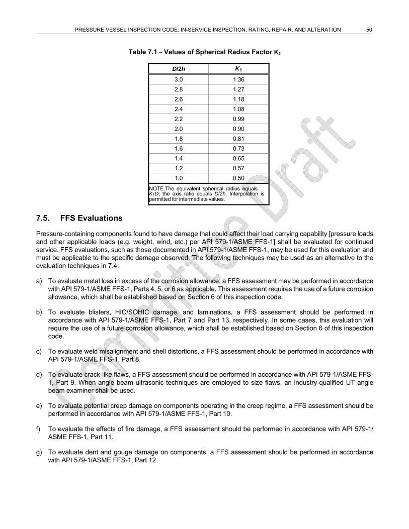
PRESSURE VESSEL INSPECTION CODE: IN-SERVICE INSPECTION, RATING, REPAIR, AND ALTERATION 50
Table 7.1 – Values of Spherical Radius Factor K1
D/2h K1
3.0 1.36
2.8 1.27
2.6 1.18
2.4 1.08
2.2 0.99
2.0 0.90
1.8 0.81
1.6 0.73
1.4 0.65
1.2 0.57
1.0 0.50
NOTE The equivalent spherical radius equals K1D; the axis ratio equals D/2h. Interpolation is permitted for intermediate values.
7.5. FFS Evaluations
Pressure-containing components found to have damage that could affect their load carrying capability [pressure loads and other applicable loads (e.g. weight, wind, etc.) per API 579-1/ASME FFS-1] shall be evaluated for continued service. FFS evaluations, such as those documented in API 579-1/ASME FFS-1, may be used for this evaluation and must be applicable to the specific damage observed. The following techniques may be used as an alternative to the evaluation techniques in 7.4.
a) To evaluate metal loss in excess of the corrosion allowance, a FFS assessment may be performed in accordance with API 579-1/ASME FFS-1, Parts 4, 5, or 6 as applicable. This assessment requires the use of a future corrosion allowance, which shall be established based on Section 6 of this inspection code.
b) To evaluate blisters, HIC/SOHIC damage, and laminations, a FFS assessment should be performed in accordance with API 579-1/ASME FFS-1, Part 7 and Part 13, respectively. In some cases, this evaluation will require the use of a future corrosion allowance, which shall be established based on Section 6 of this inspection code.
c) To evaluate weld misalignment and shell distortions, a FFS assessment should be performed in accordance with API 579-1/ASME FFS-1, Part 8.
d) To evaluate crack-like flaws, a FFS assessment should be performed in accordance with API 579-1/ASME FFS-1, Part 9. When angle beam ultrasonic techniques are employed to size flaws, an industry-qualified UT angle beam examiner shall be used.
e) To evaluate potential creep damage on components operating in the creep regime, a FFS assessment should be performed in accordance with API 579-1/ASME FFS-1, Part 10.
f) To evaluate the effects of fire damage, a FFS assessment should be performed in accordance with API 579-1/ ASME FFS-1, Part 11.
g) To evaluate dent and gouge damage on components, a FFS assessment should be performed in accordance with API 579-1/ASME FFS-1, Part 12.
PRESSURE VESSEL INSPECTION CODE: IN-SERVICE INSPECTION, RATING, REPAIR, AND ALTERATION 51
7.6. Required Thickness Determination
The required thickness shall be based on pressure, mechanical, and structural considerations using the appropriate design formulae and code allowable stress. For services with high potential consequences if failure were to occur, the engineer should consider increasing the required thickness above the calculated minimum thickness to provide for unanticipated or unknown loadings, undiscovered metal loss, or resistance to normal abuse.
7.7. Evaluation of Existing Equipment with Minimal Documentation
For pressure vessels that have no nameplate and minimal or no design and construction documentation, the following steps may be used to verify operating integrity.
1) Perform inspection to determine condition of the vessel including a complete dimensional checking of all components necessary to determine the minimum required thickness and adequacy of the design of the vessel [i.e. heads, shell(s), transitions, openings, reinforcement pads, saddle supports, etc.].
2) Define design parameters and prepare drawings.
3) Perform design calculations based on applicable construction codes and standards. Do not use allowable stress values of the current ASME Code (based on design factor of 3.5) for vessels designed to an edition or addendum of the ASME Code earlier than the 1999 addendum and was not designed to ASME Code Case 2290 or ASME Code Case 2278. For vessels designed to an edition or addendum of the ASME Code earlier than the 1999 addendum and were not designed to ASME Code Case 2290 or ASME Code Case 2278, use allowable stress values of the pre-1999 ASME Code (based on design factor of 4.0 or 5.0). See ASME Code, Section VIII, Division 1, Paragraph UG-10(c) for guidance on evaluation of unidentified materials. If UG-10(c) is not followed, then for carbon steels, use allowable stresses for SA-283 Grade C and for alloy and nonferrous materials, use X-ray fluorescence analysis to determine material type on which to base allowable stress values. When the extent of radiography originally performed is not known, use joint efficiency of 0.7 for Type No. (1) and 0.65 for Type No. (2) butt welds and 0.85 for seamless shells, heads, and nozzles or consider performing radiography if a higher joint efficiency is needed. (Recognize that performing radiography on welds in a vessel with minimal or no design and construction documentation may result in the need for a FFS evaluation and significant repairs.)
a. Material - See ASME Code, Section VIII, Division 1, Paragraph UG-10(c) for guidance on evaluation of unidentified materials. If UG-10(c) is not followed, then for carbon steels, use allowable stresses for SA-283 Grade C and for alloy and nonferrous materials, use X-ray fluorescence analysis to determine material type on which to base allowable stress values.
b. Allowable Stress - Do not use allowable stress values of the current ASME Code for vessels designed to an edition or addendum of the ASME Code due to the change in design factor used to establish allowable stress values. A reasonable assumption of year of construction must be made to determine the ASME CODE edition to obtain a allowable stress value. The following table provides a reference to the change in design factor with respect to time.
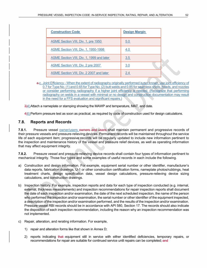
PRESSURE VESSEL INSPECTION CODE: IN-SERVICE INSPECTION, RATING, REPAIR, AND ALTERATION 52
Construction Code Design Margin
ASME Section VIII, Div. 1, pre 1950 5.0
ASME Section VIII, Div. 1, 1950-1998 4.0
ASME Section VIII, Div. 1, 1999 and later 3.5
ASME Section VIII, Div. 2 pre 2007 3.0
ASME Section VIII, Div. 2 2007 and later 2.4
a.c. Joint Efficiency - When the extent of radiography originally performed is not known, use joint efficiency of 0.7 for Type No. (1) and 0.65 for Type No. (2) butt welds and 0.85 for seamless shells, heads, and nozzles or consider performing radiography if a higher joint efficiency is needed. (Recognize that performing radiography on welds in a vessel with minimal or no design and construction documentation may result in the need for a FFS evaluation and significant repairs.)
3)4) Attach a nameplate or stamping showing the MAWP and temperature, MAT, and date.
4)5) Perform pressure test as soon as practical, as required by code of construction used for design calculations.
7.8. Reports and Records
7.8.1. Pressure vessel owner/users owners and users shall maintain permanent and progressive records of their pressure vessels and pressure-relieving devices. Permanent records will be maintained throughout the service life of each equipment item; progressive records will be regularly updated to include new information pertinent to the inspection and maintenance history of the vessel and pressure relief devices, as well as operating information that may affect equipment integrity.
7.8.2. Pressure vessel and pressure-relieving device records shall contain four types of information pertinent to mechanical integrity. Those four types and some examples of useful records in each include the following.
a) Construction and design information. For example, equipment serial number or other identifier, manufacturer’s data reports, fabrication drawings, U-1 or other construction certification forms, nameplate photos/rubbings, heat treatment charts, design specification data, vessel design calculations, pressure-relieving device sizing calculations, and construction drawings.
b) Inspection history. For example, inspection reports and data for each type of inspection conducted (e.g. internal, external, thickness measurements) and inspection recommendations for repair inspection reports shall document the date of each inspection and/or examination, the date of the next scheduled inspection, the name of the person who performed the inspection and/or examination, the serial number or other identifier of the equipment inspected, a description of the inspection and/or examination performed, and the results of the inspection and/or examination. Pressure vessel RBI records should be in accordance with API 580, Section 17. The records should also indicate the disposition of each inspection recommendation, including the reason why an inspection recommendation was not implemented.
c) Repair, alteration, and rerating information. For example,
1) repair and alteration forms like that shown in Annex D;
2) reports indicating that equipment still in service with either identified deficiencies, temporary repairs, or recommendations for repair are suitable for continued service until repairs can be completed; and
PRESSURE VESSEL INSPECTION CODE: IN-SERVICE INSPECTION, RATING, REPAIR, AND ALTERATION 53
3) rerating documentation (including rerating calculations, new design conditions, and evidence of stamping).
d) FFS assessment documentation requirements are described in API 579-1/ASME FFS-1, Part 2.8. Specific documentation requirements for the type of flaw being assessed are provided in the appropriate part of API 579-1/ ASME FFS-1.
7.8.3. Site operating and maintenance records, such as operating conditions, including process upsets that may affect mechanical integrity, and mechanical damage from maintenance should also be available to the inspector. Refer to API 572, Annex C for example inspection recordkeeping forms.
7.8.3.7.8.4. Documented results of the inspection shall be approved by the responsible owner/user inspector, engineer, or designee and should be posted into the appropriate inspection data management system within 60 days of the completion of the inspection and/or turnaround.
8. Repairs, Alterations, and Rerating of Pressure Vessels and Pressure-relieving Devices
8.1. Repairs and Alterations
8.1.1. General
All repairs and alterations to pressure vessels shall be performed by a repair organization in accordance with the applicable principles of the ASME Code or the applicable construction or repair code and the equipment specific repair plan prepared by the inspector or engineer. Repairs to pressure-relieving devices should be in accordance with API 576 and the approved relief valve QA manual. The repair organization shall follow all applicable safety requirements as designated in 5.3.
8.1.2. Authorization
All repair and alteration work shall be authorized by the inspector before the work is started by a repair organization. Authorization for alterations to pressure vessels that comply with ASME Code, Section VIII, Divisions 1 and 2 and for repairs to pressure vessels that comply with ASME Code, Section VIII, Division 2 may not be given until an engineer has also authorized the work. The inspector will designate the hold points that are required for repairs and alterations. The inspector may give prior general authorization for limited or routine repairs on a specific vessel provided the inspector is satisfied with the competency of the repair organization and the repairs are the kind that will not require a pressure test [e.g. weld overlay of corrosion on a vessel that does not require postweld heat treatment (PWHT)].
8.1.3. Approval
8.1.3.1. Before any repairs or alterations are performed, all proposed methods of design, execution, materials, welding procedures, NDE, and testing shall be approved by the inspector or engineer. For alterations, major repairs, and temporary repairs, approval by both the inspector and engineer is required. The inspector may establish hold points to be implemented during the work execution.
8.1.3.2. The inspector shall approve all specified repair and alteration work at designated hold points and after completion of the work in accordance with the repair plan.
8.1.4. Design
New vessel nozzles, connections, or replacement parts shall meet the design requirements of the applicable construction code. The design of replacement parts and new nozzles shall employ the same allowable stress criteria as used for the vessel design. Design, location, and method of attachment shall comply with requirements of the applicable construction code. When damage to parts of a vessel is so great that repairs cannot restore them to design requirements, the parts shall be replaced. An engineer shall approve all nozzle installations.
PRESSURE VESSEL INSPECTION CODE: IN-SERVICE INSPECTION, RATING, REPAIR, AND ALTERATION 54
8.1.5. Material
The material used in making repairs or alterations shall conform to the applicable construction code. Material markings, material control practices and material test reports provided to owner/user shall comply with the applicable construction code. Materials used for welded repairs and alterations shall be of known weldable quality and be compatible with the original material. Carbon or alloy steel with carbon content over 0.35 % shall not be welded and carbon steel with carbon contents over 0.30 % may need special attention and preheating to avoid weld cracking. If the inspector believes there is any question about material verification documents, PMI should be specified.
8.1.6. Defect Repairs
Repairs to defects found in pressure vessel components may be made by several techniques often dependent upon the size and nature of the defect, the materials of construction, and the design requirements of the pressure vessel. Refer to ASME PCC-2, Article 3.4 for guidance on flaw excavation and weld repair. Repair techniques can be classified as permanent or temporary depending upon their design and conformance to the applicable construction code.
8.2. Temporary Repairs
8.2.1. General
Temporary repairs may be conducted on pressure vessels as long as the inspector and engineer are satisfied that the repair will render the vessel fit for continued service until permanent repairs can be conducted. Temporary repairs should be removed and replaced with suitable permanent repairs at the next available maintenance opportunity. Temporary repairs may remain in place for a longer period of time only if evaluated, approved, and documented by the engineer and inspector. Documentation of temporary repairs should include:
a) location of the temporary repair;
b) specific details about the repair (e.g. material of construction, thickness, size of welds, NDE performed);
c) details of analyses performed, including engineering calculations demonstrating that the vessel is fit for service until permanent repairs or replacement is completed;
d) requirements for future inspections; and
e) due date for installing permanent repair.
The inspection plans shall include monitoring the integrity of the temporary repair until permanent repairs are complete. Refer to ASME PCC-2, Articles 2.4 and 3.6 for guidance on welded leak box and mechanical clamp repairs.
8.2.2. Fillet-welded Patches
8.2.2.1. Fillet-welded patches may be used to make temporary repairs to damaged, corroded, or eroded areas of pressure vessel components. Cracks shall not be repaired in this manner unless the engineer determines that the cracks will not be expected to propagate from under the patch. In some cases, the engineer may need to perform a FFS analysis. Temporary repairs using fillet-welded patches shall be approved by an inspector and engineer.
8.2.2.2. Fillet-welded patches require special design consideration, especially related to welded joint efficiency.
a) Fillet-welded patches may be applied to the internal or external surfaces of shells, heads, and headers. They would preferably be applied on the external surface to facilitate on-stream examination.
b) The fillet-welded patches are designed to absorb the membrane strain of the parts so that in accordance with the rules of the applicable construction code, the following result:
PRESSURE VESSEL INSPECTION CODE: IN-SERVICE INSPECTION, RATING, REPAIR, AND ALTERATION 55
1) The allowable membrane stress is not exceeded in the vessel parts or the patches.
2) The strain in the patches does not result in fillet-weld stresses that exceed allowable stresses for such Welds.
Exceptions to this requirement shall be justified with an appropriate FFS analysis.
c) Article 2.12 of ASME PCC-2 may be used for designing a fillet-welded patch.
8.2.2.3. A fillet-welded patch shall not be installed on top of an existing fillet-welded patch except as additional opening reinforcement, if permitted by the applicable construction code. When installing a fillet-welded patch adjacent to an existing fillet-welded patch, the distance between the toes of the fillet weld shall not be less than:
𝑑 4√𝑅𝑡
where
d is the minimum distance between toes of fillet welds of adjacent fillet weld attachments, in in. (mm);
R is the inside radius of the vessel, in in. (mm);
t is the actual thickness of the underlying vessel wall, in in. (mm).
Exceptions to this requirement in some low-consequence environments (e.g. low-pressure catalyst erosion services) shall be justified by an appropriate combination of FFS and risk analyses.
8.2.2.4. Fillet-welded patch plates shall have rounded corners with a minimum radius of 1 in. (25 mm) minimum radius.
8.2.3. Lap Band Repairs
A full encirclement lap band repair may be considered if the following requirements are met.
a) The design is approved and documented by the engineer and inspector.
b) Cracks shall not be repaired in this manner unless the engineer determines that the cracks will not be expected to propagate from under the lap band. In some cases, the engineer may need to perform a FFS analysis.
c) The band is designed to contain the full vessel design pressure.
d) All longitudinal seams in the repair band are full-penetration butt welds with the design joint efficiency and inspection consistent with the appropriate code.
e) The circumferential fillet welds attaching the band to the vessel shell are designed to transfer the full longitudinal load in the vessel shell, using a joint efficiency of 0.45. Where significant, the eccentricity effects of the band relative to the original shell shall be considered in sizing the band attachment welds.
f) Appropriate surface NDE shall be conducted on all attachment welds.
g) Fatigue of the attachment welds, such as fatigue resulting from differential expansion of the band relative to the vessel shell, should be considered, if applicable.
h) The band material and weld metal are suitable for contact with the contained fluid at the design conditions and an appropriate corrosion allowance is provided in the band.
(7)
PRESSURE VESSEL INSPECTION CODE: IN-SERVICE INSPECTION, RATING, REPAIR, AND ALTERATION 56
i) The damage mechanism leading to the need for repair shall be considered in determining the need for any additional monitoring and future inspection of the repair.
See ASME PCC-2, Article 2.6 on full encirclement sleeves for vessel nozzles.
8.2.4. Nonpenetrating Nozzles
Nonpenetrating nozzles (including pipe caps attached as nozzles) may be used to make temporary repairs to damaged pressure vessel components. Nonpenetrating nozzles (including pipe caps attached as nozzles) may be used as permanent repairs for other than cracks when the design and method of attachment comply with the applicable requirements of the appropriate code. The design and reinforcement of such nozzles shall consider the loss of the original shell material enclosed by the nozzle. The nozzle material shall be suitable for contact with the contained fluid at the design conditions and an appropriate corrosion allowance shall be provided. The damage mechanism leading to the need for repair shall be considered in determining the need for any additional monitoring and future inspection of the repair. Nonpenetrating nozzles may be used as permanent repairs for other than cracks when the design and method of attachment comply with the applicable construction code.
8.3. Permanent Repair
8.3.1. Typical permanent repair techniques include the following.
a) Excavating the defect, and blend-grinding to contour in accordance with API 579-1/ASME FFS-1, Part 5. Also refer to ASME PCC-2, Article 3.4 for guidance on flaw excavation and weld repair.
b) Excavating a defect and repair welding of the excavation.
c) Replacing a section or the component containing the defect.
d) Weld overlay of corroded area.
e) Adding strip or plate lining to the interior surface.
Repairing a crack at a discontinuity, where stress concentrations are high (e.g. crack in a nozzle-to-shell weld), should not be attempted without prior consultation with an engineer.
8.3.2. Insert Plates
Damaged or corroded shell plates may be repaired by removing a section and replacing it with an insert patch (flush patch) that meets the applicable construction codeapplicable code. Insert patches may be used if the following requirements are met.
a) Full-penetration groove welds are provided.
b) The welds are radiographed in accordance with the applicable construction code. Ultrasonic examination in accordance with ASME Code Case 2235 or ASME Code, Section VIII, Division 2, 7.5.5 may be substituted for the radiography if the NDE procedures are approved by the inspector.
c) All insert plate corners that do not extend to an existing longitudinal or horizontal weld shall be rounded having a 1 in. (25 mm) minimum radius. Weld proximity to existing welds shall be reviewed by the engineer.
Refer to ASME PCC-2, Article 2.1 for insert plate repairs.
8.3.3. Filler Metal Strength for Overlay and Repairs to Existing Welds
8.3.3.1. The filler metal used for weld repairs to vessel base metal should have minimum specified tensile
PRESSURE VESSEL INSPECTION CODE: IN-SERVICE INSPECTION, RATING, REPAIR, AND ALTERATION 57
strength equal to or greater than the minimum specified tensile strength of the base metal.
8.3.3.2. If a filler metal is used that has a minimum specified tensile strength lower than the minimum specified tensile strength of the base metal, the compatibility of the filler metal chemistry with the base metal chemistry shall be considered regarding weldability and service damage. In addition, all of the following shall be met.
a) The repair thickness shall not be more than 50 % of the required thickness of the base metal (this excludes corrosion allowance).
b) The thickness of the repair weld shall be increased by a ratio of minimum specified tensile strength of the base metal and minimum specified tensile of the filler metal used for the repair.
𝑇 𝑑 𝑆 /𝑆
where
𝑇 is the thickness of repair weld metal, in in. (mm);
𝑑 is the depth of base metal lost by corrosion and weld preparation, in in. (mm);
𝑆 is the base metal tensile strength, in ksi (MPa);
𝑆 is the filler metal tensile strength, in ksi (MPa).
c) The increased thickness of the repair shall have rounded corners and shall be blended into the base metal using a 3-to-1 taper.
d) The repair shall be made with a minimum of two passes.
8.3.4. Repairs to Stainless Steel Weld Overlay and Cladding
8.3.4.1. The repair weld procedure(s) to restore removed, corroded, or missing clad or overlay areas shall be reviewed and approved by the engineer and inspector before implementation.
8.3.4.2. Consideration shall be given to important factors that may affect the repair plan. These factors include stress level, P-number of base material, service environment, possible previously dissolved hydrogen, type of lining, deterioration of base metal properties (by temper embrittlement of chromium-molybdenum alloys or other damage mechanisms causing loss of toughness), minimum pressurization temperatures, and a need for future periodic examination.
8.3.4.3. For equipment exposed to atomic hydrogen migration in the base metal (operates in hydrogen service at an elevated temperature or has exposed base metal areas open to corrosion), these additional factors must be considered by the engineer when developing the repair plan:
a) outgassing base metal;
b) hardening of base metal due to welding, grinding, or arc gouging;
c) preheat and interpass temperature control;
d) PWHT to reduce hardness and restore mechanical properties.
(8)
PRESSURE VESSEL INSPECTION CODE: IN-SERVICE INSPECTION, RATING, REPAIR, AND ALTERATION 58
These repairs shall be monitored by an inspector to assure compliance to repair requirements. After cooling to ambient temperatures, the repair shall be inspected by the PT method, according to ASME Code, Section VIII, Division I, Appendix 8.
8.3.4.4. For vessels constructed with P-3, P-4, or P-5 base materials, the base metal in the area of repair should also be examined for cracking by the ultrasonic examination in accordance with ASME Code, Section V, Article 4, Paragraph T-473. This inspection is most appropriately accomplished following a delay of at least 24 hours after completed repairs for alloys that could be affected by delayed cracking.
8.3.4.5. Refer to ASME PCC-2, Article 2.11 for additional information on weld overlay and clad restoration.
8.4. Welding and Hot Tapping
8.4.1. General
All repair and alteration welding shall be in accordance with the applicable requirements of the ASME Code or the applicable construction or repair code, except as permitted in 8.1.6.3. Refer to API 582 and API 577 for additional welding considerations. Refer to API 2201 for safety aspects when making on-stream welds (e.g. during hot tapping) and to ASME PCC-2, Article 2.10 for technical guidance for in-service welding
8.4.2. Procedures, Qualifications, and Records
8.4.2.1. The repair organization shall use welders and welding procedures that are qualified in accordance with ASME Code, Section IX or those referenced by the construction code. Inspectors shall verify that welders are welding within their ranges qualified on the welding procedure qualification(s)welder’s performance qualifications (WPQ) and within the ranges on the specified welding procedure specification (WPS).
8.4.2.2. The repair organization shall maintain and shall make available to the inspector the following records, before the start of welding:records of its qualified welding procedures and its procedure qualification records. These records shall be available to the inspector before the start of welding.
a) qualified WPS with their supporting procedure qualification record (PQR),
b) welder’s qualification records,
c) welder continuity logs (a record that validates whether a welder has maintained his/her qualifications)
d) weld maps or other means to identify who made specific welds
e) Any other specific specified by the owner/user.
8.4.2.3. API 577 provides guidance on how to review weld procedures, procedure qualification records, welder performance qualifications, and how to respond to welding nonconformances.
8.4.3. Preheating
Preheat temperature used in making welding repairs shall be in accordance with the applicable code and qualified welding procedure. Exceptions shall be approved by the engineer, and will require a new WPS be applied if the exception is a cooler preheat than specified in the current WPS. The inspector should assure that the minimum preheat temperature is measured and maintained. For alternatives to traditional welding preheat, refer to ASME PCC-2, Article 2.8.
PRESSURE VESSEL INSPECTION CODE: IN-SERVICE INSPECTION, RATING, REPAIR, AND ALTERATION 59
8.5. Postweld Heat Treatment (PWHT)
8.5.1. General
PWHT of pressure vessel repairs or alterations should be made using the relevant requirements of the ASME Code, the applicable construction code, or an approved alternative PWHT procedure defined in 8.6. For field heat treating of vessels, refer to ASME PCC-2, Article 2.14.
8.5.2. Local PWHT
Local PWHT may be substituted for 360° banding on local repairs on all materials, provided that the following precautions are taken and requirements are met.
a) The application is reviewed, and a procedure is developed by an engineer experienced in the appropriate engineering specialties.
b) The suitability of the procedure shall be evaluated considering the following factors:
1) base metal thickness;
2) decay thermal gradients;
3) material properties (hardness, constituents, strength, etc;);
4) changes due to local PWHT;
5) the need for full-penetration welds;
6) surface and volumetric examinations after local PWHT;
7) the overall and local strains and distortions resulting from the heating of a local restrained area of the pressure vessel shell.
c) A preheat of 300 °F (150 °C) or higher, as specified by specific welding procedures, is maintained during welding.
d) The required local PWHT temperature shall be maintained for a distance of not less than two times the base metal thickness measured from the toe of the weld. The local PWHT temperature shall be monitored by a suitable number of thermocouples (at least two). When determining the number of thermocouples necessary, the size and shape of the area being heat treated should be considered.
e) Controlled heat shall be applied to any nozzle or any attachment within the local PWHT area.
f) When PWHT is performed for environmental-assisted cracking resistance, a metallurgical review shall be conducted to assess whether the procedure is acceptable.
8.6. Preheat or Controlled-deposition Welding (CDW) Methods as Alternatives to PWHT
8.6.1. General
8.6.1.1. Refer to ASME PCC-2, Article 2.9 for additional information on alternatives to PWHT.
8.6.1.2. Preheat and CDW, as described in 8.6.2 and 8.6.3, may be used in lieu of PWHT where PWHT is inadvisable or mechanically unnecessary. Prior to using any alternative method, a metallurgical review conducted by an engineer shall be performed to assure the proposed alternative is suitable for the application. The review
PRESSURE VESSEL INSPECTION CODE: IN-SERVICE INSPECTION, RATING, REPAIR, AND ALTERATION 60
should consider factors such as the reason for the original PWHT of the equipment, susceptibility to stress corrosion cracking, stresses in the location of the weld, susceptibility to high-temperature hydrogen attack, susceptibility to creep, etc. The inspector is responsible for verifying that the methods used are in accordance with owner/user specification and the requirements of this section.
8.6.1.3. Selection of the welding method used shall be based on the rules of the construction code applicable to the work planned along with technical consideration of the adequacy of the weld in the as-welded condition at operating and pressure test conditions.
8.6.1.4. When reference is made in this section to materials by the ASME designation, P-number, and group number, the requirements of this section apply to the applicable materials of the applicable construction codeoriginal code of construction, either ASME or other, which conform by chemical composition and mechanical properties to the ASME P-number and group number designations.
8.6.1.5. Vessels constructed of steels other than those listed in 8.6.2 and 8.6.3, that initially required PWHT, shall be postweld heat treated if alterations or repairs involving pressure boundary welding are performed. When one of the following methods is used as an alternative to PWHT, the PWHT joint efficiency factor may be continued if the factor has been used in the currently rated design.
8.6.2. Preheating Method (Notch Toughness Testing Not Required)
8.6.2.1. The preheating method, when performed in lieu of PWHT, is limited to the following materials and weld processes.
a) The materials shall be limited to P-No. 1, Groups 1, 2, and 3 and to P-No. 3, Groups 1 and 2 (excluding Mn-Mo steels in Group 2).
b) The welding shall be limited to the shielded metal arc welding (SMAW), gas metal arc welding (GMAW), and gas tungsten arc welding (GTAW) processes.
8.6.2.2. The preheat method shall be performed as follows.
a) The weld area shall be preheated and maintained at a minimum temperature of 300 °F (150 °C) during welding.
b) The 300 °F (150 °C) temperature should be checked to assure that 4 in. (100 mm) of the material or four times the material thickness (whichever is greater) on each side of the groove is maintained at the minimum temperature during welding. The maximum interpass temperature shall not exceed 600 °F (315 °C).
c) When the weld does not penetrate through the full thickness of the material, the minimum preheat and maximum interpass temperatures need only be maintained at a distance of 4 in. (100 mm) or four times the depth of the repair weld, whichever is greater on each side of the joint.
NOTE Notch toughness testing is not required when using this preheat method in lieu of PWHT.
8.6.3. CDW Method (Notch Toughness Testing Required)
The CDW method may be used in lieu of PWHT in accordance with the following.
a) Notch toughness testing, such as that established by ASME Code, Section VIII, Division 1, Parts UG-84 and UCS- 66 is necessary when impact tests are required by the applicable construction codeoriginal code of construction or the construction code applicable to the work planned.
b) The materials shall be limited to P-No. 1, P-No. 3, and P-No. 4 steels.
c) The welding shall be limited to the SMAW, GMAW, and GTAW processes.
PRESSURE VESSEL INSPECTION CODE: IN-SERVICE INSPECTION, RATING, REPAIR, AND ALTERATION 61
d) A weld procedure specification shall be developed and qualified for each application. The welding procedure shall define the preheat temperature and interpass temperature and include the postheating temperature requirement in Item f) 8). The qualification thickness for the test plates and repair grooves shall be in accordance with Table 8.1. The test material for the welding procedure qualification shall be of the same material specification (including specification type, grade, class, and condition of heat treatment) as the original material specification for the repair. If the original material specification is obsolete, the test material used should conform as much as possible to the material used for construction, but in no case shall the material be lower in strength or have a carbon content of more than 0.35 %.
e) When impact tests are required by the construction code applicable to the work planned, the procedure qualification record (PQR) shall include sufficient tests to determine if the toughness of the weld metal and the heat-affected zone of the base metal in the as-welded condition is adequate at the MDMT (such as the criteria used in ASME Code, Section VIII, Division I, Parts UG-84 and UCS 66). If special hardness limits are necessary (e.g. as set forth in NACE SP0472 and NACE MR0103) for stress corrosion cracking resistance, the PQR shall include hardness tests as well.
f) The WPS shall include the following additional requirements.
1) The supplementary essential variables of ASME Code, Section IX, Paragraph QW-250 shall apply.
2) The maximum weld heat input for each layer shall not exceed that used in the procedure qualification test.
3) The minimum preheat temperature for welding shall not be less than that used in the procedure qualification test.
4) The maximum interpass temperature for welding shall not be greater than that used in the procedure qualification test.
5) The preheat temperature shall be checked to assure that 4 in. (100 mm) of the material or four times the material thickness (whichever is greater) on each side of the weld joint will be maintained at the minimum temperature during welding. When the weld does not penetrate through the full thickness of the material, the minimum preheat temperature need only be maintained at a distance of 4 in. (100 mm) or four times the depth of the repair weld, whichever is greater on each side of the joint.
6) For the welding processes in Item c), use only electrodes and filler metals that are classified by the filler metal specification with an optional supplemental diffusible-hydrogen designator of H8 or lower. When shielding gases are used with a process, the gas shall exhibit a dew point that is no higher than –60 °F (–50 °C). Surfaces on which welding will be done shall be maintained in a dry condition during welding and free of rust, mill scale, and hydrogen-producing contaminants such as oil, grease, and other organic materials.
7) The welding technique shall be a CDW, temper bead, or half bead technique. The specific technique shall be used in the procedure qualification test.
8) For welds made by SMAW, after completion of welding and without allowing the weldment to cool below the minimum preheat temperature, the temperature of the weldment shall be raised to a temperature of 500 °F ± 50 °F (260 °C ± 30 °C) for a minimum period of two hours to assist outgassing diffusion of any weld metal hydrogen picked up during welding. This hydrogen bakeout treatment may be omitted provided the electrode used is classified by the filler metal specification with an optional supplemental diffusible-hydrogen designator of H4 (such as E7018-H4).
9) After the finished repair weld has cooled, the final temper bead reinforcement layer shall be removed leaving the weld substantially flush with the surface of the base material.
Refer to WRC Bulletin 412 for additional supporting technical information regarding CDW.
Table 8.1 – Qualification Limits for Base Metal and Weld Deposit Thicknesses for the CDW Method (Notch Toughness Testing Required)
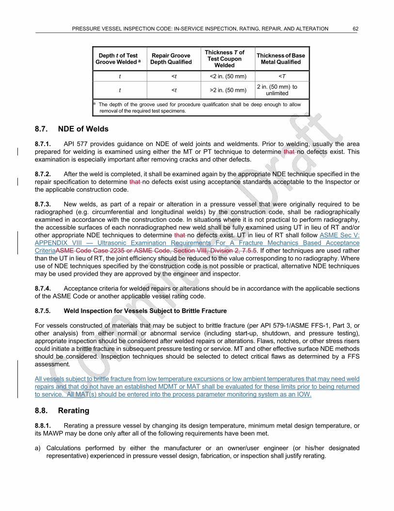
PRESSURE VESSEL INSPECTION CODE: IN-SERVICE INSPECTION, RATING, REPAIR, AND ALTERATION 62
Depth t of Test Groove Welded a
Repair Groove Depth Qualified
Thickness T of Test Coupon
Welded
Thickness of Base Metal Qualified
t <t <2 in. (50 mm) <T
t <t >2 in. (50 mm) 2 in. (50 mm) to
unlimited
a The depth of the groove used for procedure qualification shall be deep enough to allow removal of the required test specimens.
8.7. NDE of Welds
8.7.1. API 577 provides guidance on NDE of weld joints and weldments. Prior to welding, usually the area prepared for welding is examined using either the MT or PT technique to determine that no defects exist. This examination is especially important after removing cracks and other defects.
8.7.2. After the weld is completed, it shall be examined again by the appropriate NDE technique specified in the repair specification to determine that no defects exist using acceptance standards acceptable to the Inspector or the applicable construction code.
8.7.3. New welds, as part of a repair or alteration in a pressure vessel that were originally required to be radiographed (e.g. circumferential and longitudinal welds) by the construction code, shall be radiographically examined in accordance with the construction code. In situations where it is not practical to perform radiography, the accessible surfaces of each nonradiographed new weld shall be fully examined using UT in lieu of RT and/or other appropriate NDE techniques to determine that no defects exist. UT in lieu of RT shall follow ASME Sec V: APPENDIX VIII — Ultrasonic Examination Requirements For A Fracture Mechanics Based Acceptance CriteriaASME Code Case 2235 or ASME Code, Section VIII, Division 2, 7.5.5. If other techniques are used rather than the UT in lieu of RT, the joint efficiency should be reduced to the value corresponding to no radiography. Where use of NDE techniques specified by the construction code is not possible or practical, alternative NDE techniques may be used provided they are approved by the engineer and inspector.
8.7.4. Acceptance criteria for welded repairs or alterations should be in accordance with the applicable sections of the ASME Code or another applicable vessel rating code.
8.7.5. Weld Inspection for Vessels Subject to Brittle Fracture
For vessels constructed of materials that may be subject to brittle fracture (per API 579-1/ASME FFS-1, Part 3, or other analysis) from either normal or abnormal service (including start-up, shutdown, and pressure testing), appropriate inspection should be considered after welded repairs or alterations. Flaws, notches, or other stress risers could initiate a brittle fracture in subsequent pressure testing or service. MT and other effective surface NDE methods should be considered. Inspection techniques should be selected to detect critical flaws as determined by a FFS assessment.
All vessels subject to brittle fracture from low temperature excursions or low ambient temperatures that may need weld repairs and that do not have an established MDMT or MAT shall be evaluated for these limits prior to being returned to service. All MAT(s) should be entered into the process parameter monitoring system as an IOW.
8.8. Rerating
8.8.1. Rerating a pressure vessel by changing its design temperature, minimum metal design temperature, or its MAWP may be done only after all of the following requirements have been met.
a) Calculations performed by either the manufacturer or an owner/user engineer (or his/her designated representative) experienced in pressure vessel design, fabrication, or inspection shall justify rerating.
PRESSURE VESSEL INSPECTION CODE: IN-SERVICE INSPECTION, RATING, REPAIR, AND ALTERATION 63
b) A rerating shall be performed in accordance with the requirements of the vessel’s applicable construction codeconstruction code. Alternately, and when not prohibited by the jurisdiction where the pressure vessel operates, calculations can be made using the appropriate formulas in the latest edition of the applicable construction code provided all of the vessel’s essential details comply with the applicable requirements of the ASME Code. If the vessel was designed to an edition or addendum of the ASME Code earlier than the 1999 addendum and was not designed to ASME Code Case 2290 or ASME Code Case 2278, it may be rerated to the latest edition/addendum of the ASME Code if permitted by Figure 8.1. Notice that for vessels built to a code earlier than 1968 the original design allowable stress (based on design factor of 4.0 or 5.0) shall be used.
c) Current inspection records verify that the pressure vessel is satisfactory for the proposed service conditions and that the corrosion allowance provided is appropriate. An increase in allowable working pressure or design temperature shall be based on thickness data obtained from a recent internal or on-stream inspection.
d) The vessel shall be pressure tested using the applicable testing formula from the code used to perform the rerating calculations unless either of the following is true:
1) the pressure vessel has at some time been pressure tested to a test pressure equal to or higher than the test pressure required by the construction code and
2) the vessel integrity is confirmed by special nondestructive evaluation inspection techniques in lieu of testing.
e) The rerating is acceptable to the engineer.
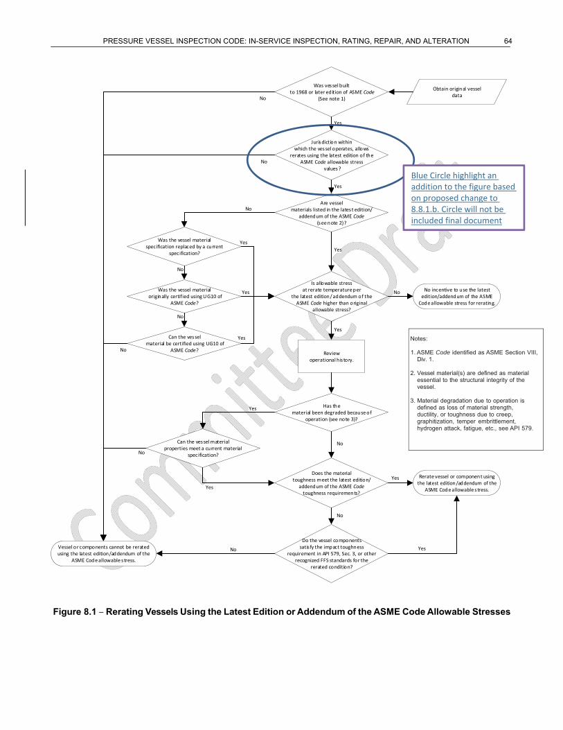
PRESSURE VESSEL INSPECTION CODE: IN-SERVICE INSPECTION, RATING, REPAIR, AND ALTERATION 64
Obtain original vessel data
Was vessel built to 1968 or later edition of ASME Code
(See note 1)
Jurisdiction within which the vessel operates, allows
rerates using the latest edition of the ASME Code allowable stress
values?
Are vesselmaterials listed in the latest edition/
addendum of the ASME Code(see note 2)?
Is allowable stress at rerate temperature per
the latest edition/ addendum of the ASME Code higher than original
allowable stress?
Reviewoperational his tory.
Has thematerial been degraded because of
operation (see note 3)?
Does the material toughness meet the latest edition/
addendum of the ASME Code toughness requirements?
Do the vessel components satis fy the impact toughness
requirement in API 579, Sec. 3, or other recognized FFS standards for the
rerated condition?
Rerate vessel or component using the latest edition/addendum of the
ASME Code allowable s tress.
Yes
No
Yes
No
Vessel or components cannot be rerated using the latest edition/addendum of the
ASME Code allowable s tress.
No
No incentive to use the latest edition/addendum of the ASME
Code allowable stress for rerating.
No
Yes
Yes
Yes
Yes
Can the vessel material properties meet a current material
specification?
Yes
Yes
No
Was the vessel material specification replaced by a current
specification?
Was the vessel material originally certified using UG10 of
ASME Code?
Can the vessel material be certified using UG10 of
ASME Code?
No
Yes
Yes
Yes
No
No
No
No
No
Figure 8.1 – Rerating Vessels Using the Latest Edition or Addendum of the ASME Code Allowable Stresses
Notes: 1. ASME Code identified as ASME Section VIII,
Div. 1. 2. Vessel material(s) are defined as material
essential to the structural integrity of the vessel.
3. Material degradation due to operation is
defined as loss of material strength, ductility, or toughness due to creep, graphitization, temper embrittlement, hydrogen attack, fatigue, etc., see API 579.
Blue Circle highlight an addition to the figure based on proposed change to 8.8.1.b. Circle will not be included final document
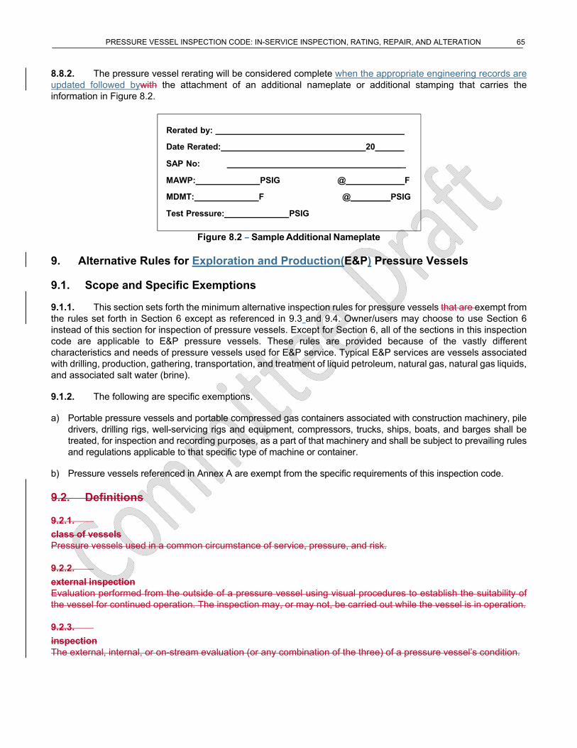
PRESSURE VESSEL INSPECTION CODE: IN-SERVICE INSPECTION, RATING, REPAIR, AND ALTERATION 65
8.8.2. The pressure vessel rerating will be considered complete when the appropriate engineering records are updated followed bywith the attachment of an additional nameplate or additional stamping that carries the information in Figure 8.2.
Figure 8.2 – Sample Additional Nameplate
9. Alternative Rules for Exploration and Production(E&P) Pressure Vessels
9.1. Scope and Specific Exemptions
9.1.1. This section sets forth the minimum alternative inspection rules for pressure vessels that are exempt from the rules set forth in Section 6 except as referenced in 9.3 and 9.4. Owner/users may choose to use Section 6 instead of this section for inspection of pressure vessels. Except for Section 6, all of the sections in this inspection code are applicable to E&P pressure vessels. These rules are provided because of the vastly different characteristics and needs of pressure vessels used for E&P service. Typical E&P services are vessels associated with drilling, production, gathering, transportation, and treatment of liquid petroleum, natural gas, natural gas liquids, and associated salt water (brine).
9.1.2. The following are specific exemptions.
a) Portable pressure vessels and portable compressed gas containers associated with construction machinery, pile drivers, drilling rigs, well-servicing rigs and equipment, compressors, trucks, ships, boats, and barges shall be treated, for inspection and recording purposes, as a part of that machinery and shall be subject to prevailing rules and regulations applicable to that specific type of machine or container.
b) Pressure vessels referenced in Annex A are exempt from the specific requirements of this inspection code.
9.2. Definitions
9.2.1.
class of vessels Pressure vessels used in a common circumstance of service, pressure, and risk.
9.2.2.
external inspection Evaluation performed from the outside of a pressure vessel using visual procedures to establish the suitability of the vessel for continued operation. The inspection may, or may not, be carried out while the vessel is in operation.
9.2.3.
inspection The external, internal, or on-stream evaluation (or any combination of the three) of a pressure vessel’s condition.
Rerated by:
Date Rerated: 20
SAP No: _
MAWP: PSIG
MDMT: F
Test Pressure: PSIG
@ F
@ PSIG
PRESSURE VESSEL INSPECTION CODE: IN-SERVICE INSPECTION, RATING, REPAIR, AND ALTERATION 66
9.2.4.
internal inspection Evaluation performed from the inside of a pressure vessel using visual and/or NDE procedures to establish the suitability of the vessel for continued operation.
9.2.5.
on-stream inspection Evaluation performed from the outside of a pressure vessel using NDE procedures to establish the suitability of the vessel for continued operation. The vessel may, or may not, be in operation while the inspection is carried out.
9.2.6.
progressive inspection An inspection whose scope (coverage, interval, technique, and so forth) is increased as a result of inspection findings.
9.2.7.
Section 9 vessel A pressure vessel that is exempted from the rules set forth in Section 6 of this document.
9.3.9.2. Inspection Program
9.3.1.9.2.1. General
Each owner/user owner or user of Section 9 vessels covered by Section 9, therefore exempted from the rules set forth in Section 6 of this document, shall have an inspection program that will assure that the vessels have sufficient integrity for the intended service. Each E&P owner/user owner or user shall have the option of employing, within the limitations of the jurisdiction in which the vessels are located, any appropriate engineering, inspection, classification, and recording systems that meet the requirements of this document.
9.3.2.9.2.2. On-stream or Internal Inspections
Either an on-stream inspection or an internal inspection may be used interchangeably to satisfy inspection requirements.
a) An internal inspection is required when the vessel integrity cannot be established with an on-stream inspection. When an on-stream inspection is used, an inspection whose scope (coverage, interval, technique, and so forth) is increased as a result of inspection findings a progressive inspection shall be employed.
b) In selecting the technique(s) to be utilized for the inspection of a pressure vessel, both the condition of the vessel and the environment in which it operates should be taken into consideration. The inspection may include any number of nondestructive techniques, including visual inspection, as deemed necessary by the owner/user.
c) At each on-stream or internal inspection, the remaining corrosion rate life shall be determined as described in 7.2.
9.3.3.9.2.3. Remaining Corrosion Rate Life Determination
9.3.3.1.9.2.3.1. For a new vessel, a vessel for which service conditions are being changed, or existing vessels, the remaining corrosion rate life shall be determined for each vessel or estimated for a class of vessels (pressure vessels used in a common circumstance of service, pressure, and risk) based on the following formula:
Remaining life 𝑡 𝑡
corrosion rate
where
(9)
PRESSURE VESSEL INSPECTION CODE: IN-SERVICE INSPECTION, RATING, REPAIR, AND ALTERATION 67
𝑡 is the actual thickness, in in. (mm), measured at the time of inspection for a given location or component;
𝑡 is the required thickness, in in. (mm), at the same location or component as the tactual measurement, obtained by one of the following methods.
a) The nominal thickness in the uncorroded condition, less the specified corrosion allowance.
b) The original measured thickness, if documented, in the uncorroded condition, less the specified corrosion allowance.
c) Calculations in accordance with the requirements of the applicable construction codeconstruction code to which the pressure vessel was built or by computations that are determined using the appropriate formulas in the latest edition of the ASME Code, if all of the essential details comply with the applicable requirements of the code being used.
corrosion rate loss of metal thickness, in in. mm , per year.
For vessels in which the corrosion rate is unknown, the corrosion rate shall be determined by one of the following methods.
1) A corrosion rate may be calculated from data collected by the owner/user owner or user on vessels in the same or similar service.
2) If data on vessels providing the same or similar service is not available, a corrosion rate may be estimated from the owner/userowner’s or user’s experience or from published data on vessels providing comparable service.
3) If the probable corrosion rate cannot be determined by any of the above items, the damage mechanisms identified in the inspection plan shall be reviewed to determine if a low, medium or high corrosion rate is anticipated to determine inspection frequency.
Low [<3mpy] - on-stream performed approximately 2 years into service and again at 5 years of service.
Medium [3-15mpy] - on-stream performed at approximately 1 year of service and again at 3 years of service.
High [>15mpy] - on-stream performed at approximately 6 months of service and again at 2 years of service.
Subsequent determinations shall be made at appropriate intervals until a credible corrosion rate is established. If it is later determined that an inaccurate corrosion rate was assumed, the corrosion rate in the remaining life calculations shall be changed to the actual corrosion rate.If the probable corrosion rate cannot be determined by either Item a) or b), on-stream determination shall be made after approximately 1000 hours of service by using suitable corrosion monitoring devices or actual nondestructive thickness measurements of the vessel or system. Subsequent determinations shall be made after appropriate intervals until the corrosion rate is established.
9.3.3.2.9.2.3.2. The remaining life shall be determined by an individual experienced in pressure vessel design and/or inspection. If it is determined that an inaccurate assumption has been made for either corrosion rate or thickness, the remaining life shall be increased or decreased to agree with the actual rate or thickness.
9.3.3.3.9.2.3.3. Other failure mechanisms (stress corrosion, brittle fracture, blistering, and so forth) shall be taken into account when determining the remaining life of the vessel.
9.3.4.9.2.4. External Inspections
The following apply to external inspections.
PRESSURE VESSEL INSPECTION CODE: IN-SERVICE INSPECTION, RATING, REPAIR, AND ALTERATION 68
a) The external visual inspection shall, at least, determine the condition of the shell, heads, nozzles, exterior insulation, supports and structural parts, pressure-relieving devices, allowance for expansion, and general alignment of the vessel on its supports. Any signs of leakage should be investigated so that the sources can be established. It is not necessary to remove insulation if the entire vessel shell is maintained at a temperature sufficiently low or sufficiently high to prevent the condensation of moisture. Refer to API 572 for guidelines on external vessel inspections.
b) Buried sections of vessels shall be monitored to determine their external environmental condition. This monitoring shall be done at intervals that shall be established based on corrosion rate information obtained during maintenance activity on adjacent connected piping of similar material, information from the interval examination of similarly buried corrosion test coupons of similar material, information from representative portions of the actual vessel, or information from a sample vessel in similar circumstances.
c) Vessels that are known to have a remaining life of over 10 years or that are protected against external corrosion— for example,
1) vessels insulated effectively to preclude the entrance of moisture;
2) jacketed cryogenic vessels;
3) vessels installed in a cold box in which the atmosphere is purged with an inert gas; and
4) vessels in which the temperature being maintained is sufficiently low or sufficiently high to preclude the presence of water do not need to have insulation removed for the external inspection; however, the condition of their insulating system or their outer jacketing, such as the cold box shell, shall be observed at least every five years and repaired if necessary.
9.3.5.9.2.5. Inspection Intervals
9.3.5.1.9.2.5.1. General
The pressure vessel owner/userowner or user shall have the option to establish vessel inspection classes by grouping vessels into common classes of service, pressure, and/or risk. Vessel classifications shall be determined by an individual(s) experienced in the criteria outlined in the following. If vessels are grouped into classes (such as lower and/or higher risk), at a minimum, the following shall be considered to establish the risk class.
a) Potential for vessel failure, such as MDMT; potential for cracking, corrosion, and erosion; and the existence of mitigation factors.
b) Vessel history, design, and operating conditions, such as, the type and history of repairs or alterations, age of vessel, remaining corrosion allowance, properties of contained fluids, operating pressure, and temperature relative to design limits.
c) Consequences of vessel failure, such as location of vessel relative to employees or the public, potential for equipment damage, and environmental consequences.
9.3.5.2.9.2.5.2. RBI
RBI can be used to determine inspection intervals and the type and extent of future inspection/examinations. Refer to 5.2 for general requirements. In addition, the requirements below shall also be met:
a) An RBI assessment may be used to establish the appropriate inspection intervals for internal, on-stream, and external inspections, as well as inspection and testing intervals for pressure-relieving devices. The RBI assessment may allow previously established inspection intervals to be exceeded from limits specified in 6.4 and
PRESSURE VESSEL INSPECTION CODE: IN-SERVICE INSPECTION, RATING, REPAIR, AND ALTERATION 69
6.5 including the 10-year inspection and one-half remaining life limits for internal and on-stream inspections and the 5-year inspection limit for the external inspections.
b) When an RBI interval for the internal or on-stream inspection exceeds the 10-year limit, the RBI assessment shall be reviewed and approved by the engineer and inspector at intervals not to exceed 10 years or more often if warranted by process, equipment, or consequence changes.
c) When an RBI assessment is used to extend the internal or on-stream inspection interval, the assessment should include a review of the inspection history and potential fouling of the vessel’s pressure-relieving device(s).
9.3.5.3.9.2.5.3. Risk Classification
The following apply to inspection intervals.
a) Inspections shall be performed at intervals determined by the vessel’s risk classification. The inspection intervals for the two main risk classifications (lower and higher) are defined below. The owner/user shall define and document how to determine lower and higher risk classification. When additional classes are established, inspection and sampling intervals shall be set between the higher risk and lower risk classes as determined by the owner/userowner or user. If the owner/userowner or user decides to not classify vessels into risk classes, the inspection requirements and intervals of higher-risk vessels shall be followed. If the owner/userowner or user decides to use RBI, then the interval, extent, and methods of inspection shall be determined by the RBI analysis.
b) Lower-risk vessels shall be inspected as follows.
1) Inspections on a representative sample of vessels in that class, or all vessels in that class, may be performed.
2) External inspections shall be performed when an on-stream or internal inspection is performed or at shorter intervals at the owner/userowner or user’s option.
3) On-stream or internal inspections shall be performed at least every 15 years or three-fourths remaining corrosion rate life, whichever is less.
4) Any signs of leakage or deterioration detected in the interval between inspections shall require an on-stream or internal inspection of that vessel and a reevaluation of the inspection interval for that vessel class.
c) Higher-risk vessels shall be inspected as follows.
1) External inspections shall be performed when an on-stream or internal inspection is performed or at shorter intervals at the owner/userowner or user’s option.
2) On-stream or internal inspections shall be performed at least every 10 years or one-half remaining corrosion rate life, whichever is less.
3) In cases where the remaining life is estimated to be less than four years, the inspection interval may be the full remaining life up to a maximum of two years. Consideration should also be given to increasing the number of vessels inspected within that class to improve the likelihood of detecting the worst-case corrosion.
4) Any signs of leakage or deterioration detected in the interval between inspections shall require an on-stream or internal inspection of that vessel and a reevaluation of the inspection interval for that vessel class.
d) Pressure vessels (whether grouped into classes or not) shall be inspected at intervals sufficient to insure their fitness for continued service. Operational conditions and vessel integrity may require inspections at shorter intervals than the intervals stated above.
e) If service conditions change, the maximum operating temperature, pressure, and interval between inspections shall be reevaluated.
PRESSURE VESSEL INSPECTION CODE: IN-SERVICE INSPECTION, RATING, REPAIR, AND ALTERATION 70
f) For large vessels with two or more zones of differing corrosion rates, each zone may be treated independently regarding the interval between inspections.
9.3.6.9.2.6. Additional Inspection Requirements
Additional inspection requirements, regardless of vessel classification, exist for the following vessels.
a) Vessels that have changed ownership and location shall have an on-stream or internal inspection performed to establish the next inspection interval and to assure that the vessel is suitable for its intended service. Inspection of new vessels is not required if a manufacturer’s data report is available.
b) If a vessel is transferred to a new location, and it has been more than five years since the vessel’s last inspection, an on-stream or internal inspection is required. (Vessels in truck-mounted, skid-mounted, ship-mounted, or barge- mounted equipment are not included.)
c) Air receivers (other than portable equipment) shall be inspected at least every five years unless inspected by RBI.
d) Portable or temporary pressure vessels that are employed for the purpose of testing oil and gas wells during completion or recompletion shall be inspected at least once during each three-year period of use. More frequent inspections shall be conducted if vessels have been in severe corrosive environments.
9.4.9.3. Pressure Test
When a pressure test is conducted, the test shall be in accordance with the procedures in 5.8.
9.5.9.4. Safety Relief Devices
Safety relief devices shall be inspected, tested, and repaired in accordance with 6.6.
9.6.9.5. Records
The following records requirements apply.
a) Pressure vessel owner/user owners and users shall maintain pressure vessel records. The preferred method of recordkeeping is to maintain data by individual vessel. Where vessels are grouped into classes, data may be maintained by vessel class. When inspections, repairs, or alterations are made on an individual vessel, specific data shall be recorded for that vessel.
b) Examples of information that may be maintained are vessel identification numbers; safety relief device information; and the forms on which results of inspections, repairs, alterations, or reratings are to be recorded. Any appropriate forms may be used to record these results. A sample pressure vessel inspection record is shown in Annex C. A sample alteration or rerating of pressure vessel form is shown in Annex D. Information on maintenance activities and events that affect vessel integrity should be included in the vessel records.
PRESSURE VESSEL INSPECTION CODE: IN-SERVICE INSPECTION, RATING, REPAIR, AND ALTERATION 71
Annex A (normative)
Code Exemptions
Where a pressure vessel has been constructed to the American Society of Mechanical Engineers (ASME) Section VIII Code, API 510 is intended to apply to divisions 1 and 2. Unless specified by the owner/user, The the following classes of containers and pressure vessels are excluded from the specific requirements of this inspection code, unless specified by the owner/user.
a) Pressure vessels on movable structures covered by jurisdictional regulations:
1) cargo or volume tanks for trucks, ships, and barges;
2) air receivers associated with braking systems of mobile equipment;
3) pressure vessels installed in oceangoing ships, barges, and floating craft.
b) All The following classes of containers listed for exemption from the scope of ASME Code, Section VIII, Division 1 are as follows.;
1) Those classes of containers within the scope of other sections of the ASME Code other than Section VIII: Division I.
2)1) Fired process tubular heaters;.
3)2) Pressure containers that which are integral parts or components of rotating or reciprocating mechanical devices, such as pumps, compressors, turbines, generators, engines, and hydraulic or pneumatic cylinders where the primary design considerations or stresses are derived from the functional requirements of the device.;
4)3) Any structure Structures whose primary function is transporting fluids from one location to another within a system of which it is an integral part, that is, piping systems;part (i.e. piping systems).
5)4) Piping components such as pipe, flanges, bolting, gaskets, valves, expansion joints, and fittings, and the pressure-containing parts of other components, such as strainers and devices that which serve such purposes as mixing, separating, snubbing, distributing, and metering or controlling flow, provided that as long as the pressure-containing parts of these such components are generally recognized as piping components or accessories;.
6)5) A vessel for containing water under pressure, including vessels those containing air, the compression of which serves only as a cushion, when none of the following limitations are not exceeded:
i) a design pressure of 300 lbf/in.2psi (2067.7 KPa2 MPa),
ii) a design temperature of 210 °F (99 °C).
7)6) A hot water supply storage tank heated by steam or any other indirect means when the following limitations are not exceeded:
i) a heat input of 200,000 Btu/hr (211 × 108 J/hr58.6 kW),
ii) a water temperature of 210 °F (99 °C),
iii) a nominal water-containing capacity of 120 gal (455 450 L).
7) Vessels not exceeding the design pressure at the top of the vessel, limitations below, with no limitation on size
PRESSURE VESSEL INSPECTION CODE: IN-SERVICE INSPECTION, RATING, REPAIR, AND ALTERATION 72
i) Vessels with having an internal or external design pressure that cannotnot exceeding 15 psig (103.4100 KPa).
i)ii) Combination units having an internal or external pressure in each chamber not exceeding 15 psi (100 kPa) and differential pressure on the common elements not exceeding 15 psi (100 kPa)
8) Vessels with having an inside diameter, width, height, or cross-section diagonal not exceeding 6 in. (15 cm152 mm), but with no limitation on their length of vessel or pressure.
9) Pressure vessels for human occupancy.
c) Pressure vessels that do not exceed the following volumes and pressures:
1) 5 ft3 (0.141 m3) in volume and 250 lbf/in.2psi (1723.1 KPa1.7 MPa) design pressure,
2) 3 ft3 (0.08 m3) in volume and 350 lbf/in.2psi (2410 KPa2.4 MPa) design pressure,
3) 1 1/2 ft3 (0.042 m3) in volume and 600 lbf/in.2psi (4136.9 KPa4.1 MPa) design pressure.
PRESSURE VESSEL INSPECTION CODE: IN-SERVICE INSPECTION, RATING, REPAIR, AND ALTERATION 73
Annex B (normative)
Inspector Certification
B.1 Examination
A written examination to certify inspectors within the scope of API 510 shall be based on the current API 510 Inspector Certification Examination Body of Knowledge as published by API.
To become an authorized API pressure vessel inspector, candidates must pass the examination.
B.2 Certification
To qualify for the certification examination, the applicant’s education and experience, when combined, shall be equal to at least one of the following:
a) a Bachelor of Science degree in engineering or technology, plus one year of experience in supervision of inspection activities or performance of inspection activities as described in API 510;
b) a two-year degree or certificate in engineering or technology, plus two years of experience in the design, construction, repair, inspection, or operation of pressure vessels, of which one year must be in supervision of inspection activities or performance of inspection activities as described in API 510;
c) a high school diploma or equivalent, plus three years of experience in the design, construction, repair, inspection, or operation of pressure vessels, of which one year must be in supervision of inspection activities or performance of inspection activities as described in API 510;
d) a minimum of five years of experience in the design, construction, repair, inspection, or operation of pressure vessels, of which one year must be in supervision of inspection activities or performance of inspection activities as describe in API 510.
B.3 Recertification
B.3.1 Recertification is required three years from the date of issuance of the API 510 authorized pressure vessel inspector certificate. Recertification by written examination will be required for inspectors who have not been actively engaged as inspectors within the most recent three-year certification period. Exams will be in accordance with all provisions contained in API 510.
B.3.2 “Actively engaged as an inspector” shall be defined by one of the following provisions:
a) a minimum of 20 % of time400 hours each year spent performing inspection activities or, supervision supervising inspection activities or engineering support of inspection activities as described in the API 510 inspection code over the most recent three-year certification period;
b) performance of inspection activities or, supervision of supervising inspection activities or engineering support of inspection activities on 75 pressure vessels as described in API 510 over the most recent three-year certification period.
NOTE Inspection activities common to other API inspection documents (NDE, recordkeeping, review of welding documents, etc.) may be considered here.
B.3.3 Once every other recertification period (every six years), inspectors actively engaged as an inspector shall demonstrate knowledge of revisions to the API documents on the API 510 exam API 510 that were instituted during the previous six years. This requirement shall be effective six years from the inspector’s initial certification date.
PRESSURE VESSEL INSPECTION CODE: IN-SERVICE INSPECTION, RATING, REPAIR, AND ALTERATION 74
Inspectors who have not been actively engaged as an authorized pressure vessel inspector within the most recent three-year certification period shall recertify as required in B.3.1.
PRESSURE VESSEL INSPECTION CODE: IN-SERVICE INSPECTION, RATING, REPAIR, AND ALTERATION 75
Annex C (informative)
Sample Pressure Vessel Inspection Record
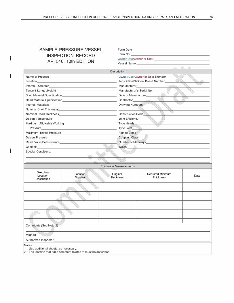
PRESSURE VESSEL INSPECTION CODE: IN-SERVICE INSPECTION, RATING, REPAIR, AND ALTERATION 76
SAMPLE PRESSURE VESSEL INSPECTION RECORD API 510, 10th EDITION
Form Date
Form No.
Owner/UserOwner or User
Vessel Name
Description
Name of Process Owner/UserOwner or User Number
Location Jurisdiction/National Board Number
Internal Diameter Manufacturer
Tangent Length/Height Manufacturer’s Serial No.
Shell Material Specification Date of Manufacture
Head Material Specification Contractor
Internal Materials Drawing Numbers
Nominal Shell Thickness
Nominal Head Thickness Construction Code
Design Temperature Joint Efficiency
Maximum Allowable Working Type Heads
Pressure Type Joint
Maximum Tested Pressure Flange Class
Design Pressure Coupling Class
Relief Valve Set Pressure Number of Manways
Contents Weight
Special Conditions.
Thickness Measurements
Sketch or Location
Description
Location Number
Original Thickness
Required Minimum Thickness
Date
Comments (See Note 2)
Method
Authorized Inspector
Notes: 1. Use additional sheets, as necessary. 2. The location that each comment relates to must be described.
PRESSURE VESSEL INSPECTION CODE: IN-SERVICE INSPECTION, RATING, REPAIR, AND ALTERATION 77
Annex D (informative)
Sample Repair, Alteration, or Rerating of Pressure Vessel Form
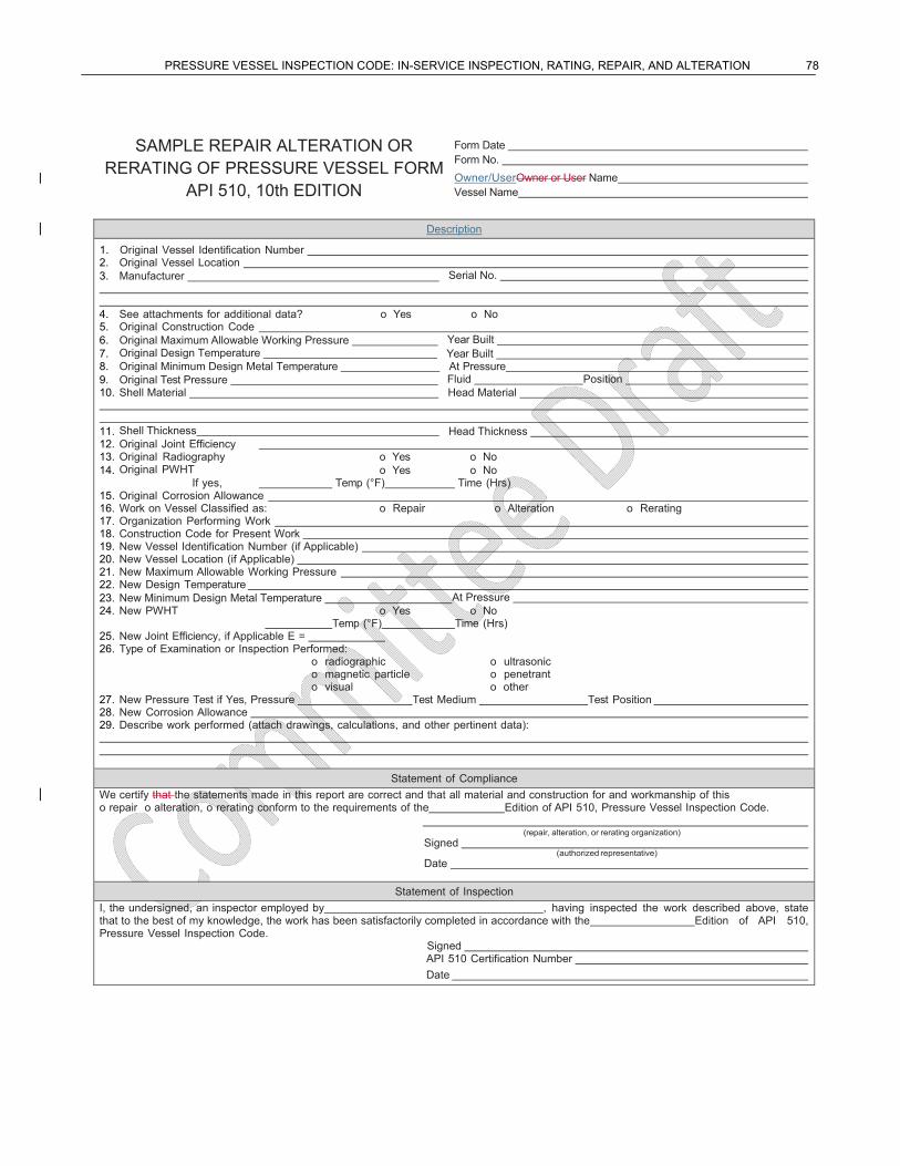
PRESSURE VESSEL INSPECTION CODE: IN-SERVICE INSPECTION, RATING, REPAIR, AND ALTERATION 78
SAMPLE REPAIR ALTERATION OR RERATING OF PRESSURE VESSEL FORM
API 510, 10th EDITION
Form Date Form No.
Owner/UserOwner or User Name Vessel Name
Description
1. Original Vessel Identification Number 2. Original Vessel Location 3. Manufacturer Serial No. 4. See attachments for additional data? o Yes o No 5. Original Construction Code 6. Original Maximum Allowable Working Pressure Year Built 7. Original Design Temperature Year Built 8. Original Minimum Design Metal Temperature At Pressure 9. Original Test Pressure Fluid Position 10. Shell Material Head Material 11. Shell Thickness Head Thickness 12. Original Joint Efficiency 13. Original Radiography o Yes o No 14. Original PWHT o Yes o No If yes, Temp (°F) Time (Hrs) 15. Original Corrosion Allowance 16. Work on Vessel Classified as: o Repair o Alteration o Rerating 17. Organization Performing Work 18. Construction Code for Present Work 19. New Vessel Identification Number (if Applicable) 20. New Vessel Location (if Applicable) 21. New Maximum Allowable Working Pressure 22. New Design Temperature 23. New Minimum Design Metal Temperature At Pressure 24. New PWHT o Yes o No
Temp (°F) Time (Hrs) 25. New Joint Efficiency, if Applicable E = 26. Type of Examination or Inspection Performed:
o radiographic o ultrasonic o magnetic particle o penetrant o visual o other 27. New Pressure Test if Yes, Pressure Test Medium Test Position 28. New Corrosion Allowance 29. Describe work performed (attach drawings, calculations, and other pertinent data):
Statement of Compliance
We certify that the statements made in this report are correct and that all material and construction for and workmanship of this o repair o alteration, o rerating conform to the requirements of the Edition of API 510, Pressure Vessel Inspection Code.
(repair, alteration, or rerating organization) Signed (authorized representative) Date
Statement of Inspection
I, the undersigned, an inspector employed by , having inspected the work described above, state that to the best of my knowledge, the work has been satisfactorily completed in accordance with the Edition of API 510, Pressure Vessel Inspection Code.
Signed
API 510 Certification Number
Date
PRESSURE VESSEL INSPECTION CODE: IN-SERVICE INSPECTION, RATING, REPAIR, AND ALTERATION 79
Annex E (informative)
Technical Inquiries
E.1 Introduction
API will consider written requests for interpretations of API 510. API staff will make such interpretations in writing after consultation, if necessary, with the appropriate committee officers and the committee membership. The API committee responsible for maintaining API 510 meets regularly to consider written requests for interpretations and revisions and to develop new criteria as dictated by technological development. The committee’s activities in this regard are limited strictly to interpretations of the standard or to the consideration of revisions to the present standard on the basis of new data or technology. As a matter of policy, API does not approve, certify, rate, or endorse any item, construction, proprietary device, or activity; thus, accordingly, inquiries requiring such consideration will be returned. Moreover, API does not act as a consultant on specific engineering problems or on the general understanding or application of the rules. If, based on the inquiry information submitted, it is the opinion of the committee that the inquirer should seek assistance, the inquiry will be returned with the recommendation that such assistance be obtained. All inquiries that cannot be understood because they lack information will be returned.
E.2 Inquiry Format
Inquiries shall be limited strictly to requests for interpretation of the standard or to the consideration of revisions to the standard on the basis of new data or technology. Inquiries shall be submitted in the following format.
a) Scope—The inquiry shall involve a single subject or closely related subjects. An inquiry letter concerning unrelated subjects will be returned.
b) Background—The inquiry letter shall state the purpose of the inquiry, which shall be either to obtain an interpretation of the standard or to propose consideration of a revision to the standard. The letter shall provide concisely the information needed for complete understanding of the inquiry (with sketches, as necessary). This information shall include reference to the applicable edition, revision, paragraphs, figures, and tables.
c) Inquiry—The inquiry shall be stated in a condensed and precise question format. Superfluous background information shall be omitted from the inquiry, and where appropriate, the inquiry shall be composed so that “yes” or “no” (perhaps with provisos) would be a suitable reply. This inquiry statement should be technically and editorially correct. The inquirer shall state what he/she believes the standard requires. If in his/her opinion a revision to the standard is needed, he/she shall provide recommended wording. The inquiry should be typed; however, legible handwritten inquiries will be considered. The name and the mailing address of the inquirer must be included with the proposal. The proposal shall be submitted to the following address: Director of the Standards Department, American Petroleum Institute, 1220 L Street, NW, Washington, DC 20005-4070, or via e-mail to [email protected].
E.3 Technical Inquiry Responses
Responses to previous technical inquiries can be found on the API website at http://mycommittees.api.org/ standards/techinterp/refequip/default.aspx

PRESSURE VESSEL INSPECTION CODE: IN-SERVICE INSPECTION, RATING, REPAIR, AND ALTERATION 80
QC Check List Make sure all references are valid Make sure all definitions are used When using ASME Code and not reference to a code case then Code must be Italics
PRESSURE VESSEL INSPECTION CODE: IN-SERVICE INSPECTION, RATING, REPAIR, AND ALTERATION 81
Bibliography
[1] API Recommended Practice 588, Source Inspection and Quality Surveillance of Fixed Equipment
[2] WRC Bulletin 4127, Challenges and Solutions in Repair Welding for Power and Processing Plants
[3] National Board NB-238, National Board Inspection Code
[4] NACE MR01039, Materials Resistant to Sulfide Stress Cracking in Corrosive Petroleum Refining Environments
[5] NACE SP0170, Protection of Austenitic Stainless Steels and Other Austenitic Alloys from Polythionic Acid Stress Corrosion Cracking During Shutdown of Refinery Equipment
[6] NACE SP0472, Methods and Controls to Prevent In-service Environmental Cracking of Carbon Steel Weldments in Corrosive Petroleum Refining Environments
7 Welding Research Council, P.O. Box 201547, Shaker Heights, Ohio 44120, www.forengineers.org. 8 The National Board of Boiler and Pressure Vessel Inspectors, 1055 Crupper Avenue, Columbus, Ohio 43229, www.nationalboard.org. 9 NACE International (formerly the National Association of Corrosion Engineers), 1440 South Creek Drive, Houston, Texas 77218-8340, www.nace.org.