Embed Size (px)
Citation preview
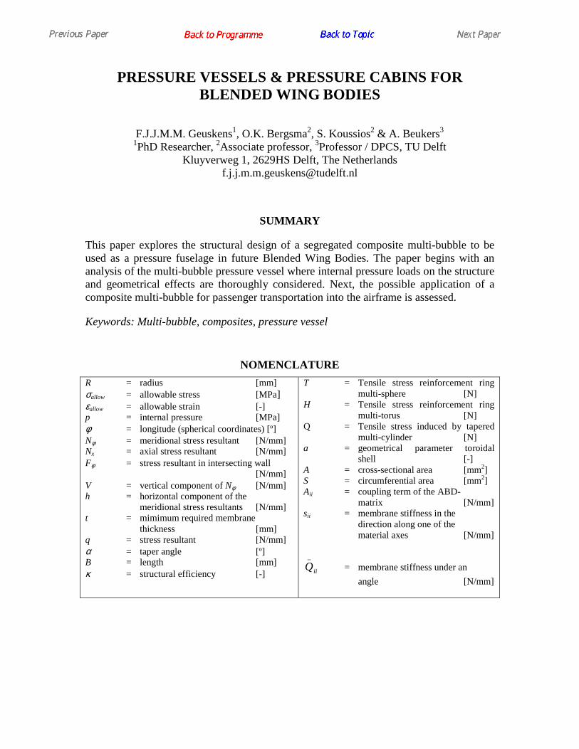
PRESSURE VESSELS & PRESSURE CABINS FOR BLENDED WING BODIES
F.J.J.M.M. Geuskens1, O.K. Bergsma2, S. Koussios2 & A. Beukers3 1PhD Researcher, 2Associate professor, 3Professor / DPCS, TU Delft
Kluyverweg 1, 2629HS Delft, The Netherlands [email protected]
SUMMARY
This paper explores the structural design of a segregated composite multi-bubble to be used as a pressure fuselage in future Blended Wing Bodies. The paper begins with an analysis of the multi-bubble pressure vessel where internal pressure loads on the structure and geometrical effects are thoroughly considered. Next, the possible application of a composite multi-bubble for passenger transportation into the airframe is assessed.
Keywords: Multi-bubble, composites, pressure vessel
NOMENCLATURE
R = radius [mm] σallow = allowable stress [MPa] εallow = allowable strain [-] p = internal pressure [MPa] φ = longitude (spherical coordinates) [º] Nφ = meridional stress resultant [N/mm] Nx = axial stress resultant [N/mm] Fφ = stress resultant in intersecting wall [N/mm] V = vertical component of Nφ [N/mm] h = horizontal component of the meridional stress resultants [N/mm] t = mimimum required membrane thickness [mm] q = stress resultant [N/mm] α = taper angle [º] B = length [mm] κ = structural efficiency [-]
T = Tensile stress reinforcement ring multi-sphere [N] H = Tensile stress reinforcement ring multi-torus [N] Q = Tensile stress induced by tapered multi-cylinder [N] a = geometrical parameter toroidal shell [-] A = cross-sectional area [mm2] S = circumferential area [mm2] Aii = coupling term of the ABD- matrix [N/mm] sii = membrane stiffness in the direction along one of the material axes [N/mm]
iiQ_
= membrane stiffness under an
angle [N/mm]
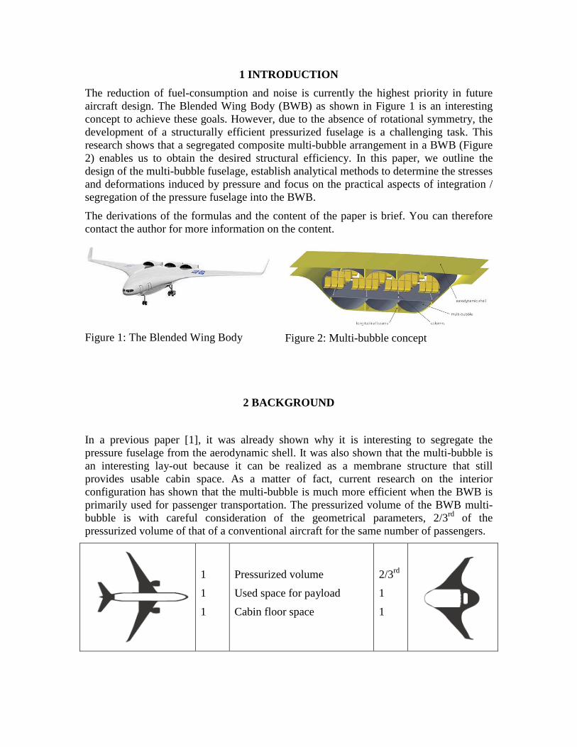
1 INTRODUCTION
The reduction of fuel-consumption and noise is currently the highest priority in future aircraft design. The Blended Wing Body (BWB) as shown in Figure 1 is an interesting concept to achieve these goals. However, due to the absence of rotational symmetry, the development of a structurally efficient pressurized fuselage is a challenging task. This research shows that a segregated composite multi-bubble arrangement in a BWB (Figure 2) enables us to obtain the desired structural efficiency. In this paper, we outline the design of the multi-bubble fuselage, establish analytical methods to determine the stresses and deformations induced by pressure and focus on the practical aspects of integration / segregation of the pressure fuselage into the BWB.
The derivations of the formulas and the content of the paper is brief. You can therefore contact the author for more information on the content.
Figure 1: The Blended Wing Body
Figure 2: Multi-bubble concept
2 BACKGROUND
In a previous paper [1], it was already shown why it is interesting to segregate the pressure fuselage from the aerodynamic shell. It was also shown that the multi-bubble is an interesting lay-out because it can be realized as a membrane structure that still provides usable cabin space. As a matter of fact, current research on the interior configuration has shown that the multi-bubble is much more efficient when the BWB is primarily used for passenger transportation. The pressurized volume of the BWB multi-bubble is with careful consideration of the geometrical parameters, 2/3rd of the pressurized volume of that of a conventional aircraft for the same number of passengers.
1
1
1
Pressurized volume
Used space for payload
Cabin floor space
2/3rd
1
1
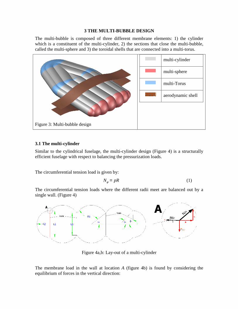
3 THE MULTI-BUBBLE DESIGN
The multi-bubble is composed of three different membrane elements: 1) the cylinder which is a constituent of the multi-cylinder, 2) the sections that close the multi-bubble, called the multi-sphere and 3) the toroidal shells that are connected into a multi-torus.
Figure 3: Multi-bubble design
multi-cylinder
multi-sphere
multi-Torus
aerodynamic shell
3.1 The multi-cylinder
Similar to the cylindrical fuselage, the multi-cylinder design (Figure 4) is a structurally efficient fuselage with respect to balancing the pressurization loads.
The circumferential tension load is given by:
N pRφ = (1)
The circumferential tension loads where the different radii meet are balanced out by a single wall. (Figure 4)
Figure 4a,b: Lay-out of a multi-cylinder
The membrane load in the wall at location A (figure 4b) is found by considering the equilibrium of forces in the vertical direction:
, 1 2 1 1 2 2cos cosmF V V N Nφ φ φφ φ= + = + (2)
The cylinders are dimensioned in such a way that the horizontal component of the membrane load of one cylinder (H1) is balanced by the horizontal component of the membrane load of the neighboring cylinder (H2). In addition, to control the geometry of the frontal area, bubbles with different diameters can be connected.
In order to have horizontal equilibrium at location A, we must respect the following condition:
2 2 1 1sin sinR Rφ φ= (3)
When the elastic properties of the material of the multi-cylinder are the same and all sections are loaded at the same stress level, the thickness of each section will be:
/ allowt Nφ φ σ= (4)
In this case, all displacements are uniform and the geometry is linearly scaled because all strains are equal.
The structural efficiency of a fuselage is defined as the ratio of the volume of the vessel and the amount of material needed to contain this volume. Considering a cross-section of the fuselage the internal volume is represented by the frontal area A of the multi-bubble and the amount of material by the circumferential cross sectional area S.
In an earlier paper [1], the following relationship has been derived for the structural efficiency in the circumferential direction:
2allowA
S p
σ= (5)
The relationship shows that the shape of the cross-section (amount of cylinders, diameter of cylinders) does not influence the structural efficiency.
3.2 The Multi-sphere
The spheres that close off the multi-cylinder are also structurally efficient shell-structures with respect to balancing the pressurization loads. The stress resultants for the sphere are given by:
2
pRN Nφ θ= = (6)
The condition to obtain equilibrium for the multi-cylinder (equation 3) also holds for the multi-sphere. Assuming horizontal equilibrium at the intersection and the stress resultant in the radial direction becomes:
,1 1 2 2,
cos cos
2 2m
c
FpR pRF φ
φφ φ+= = (7)
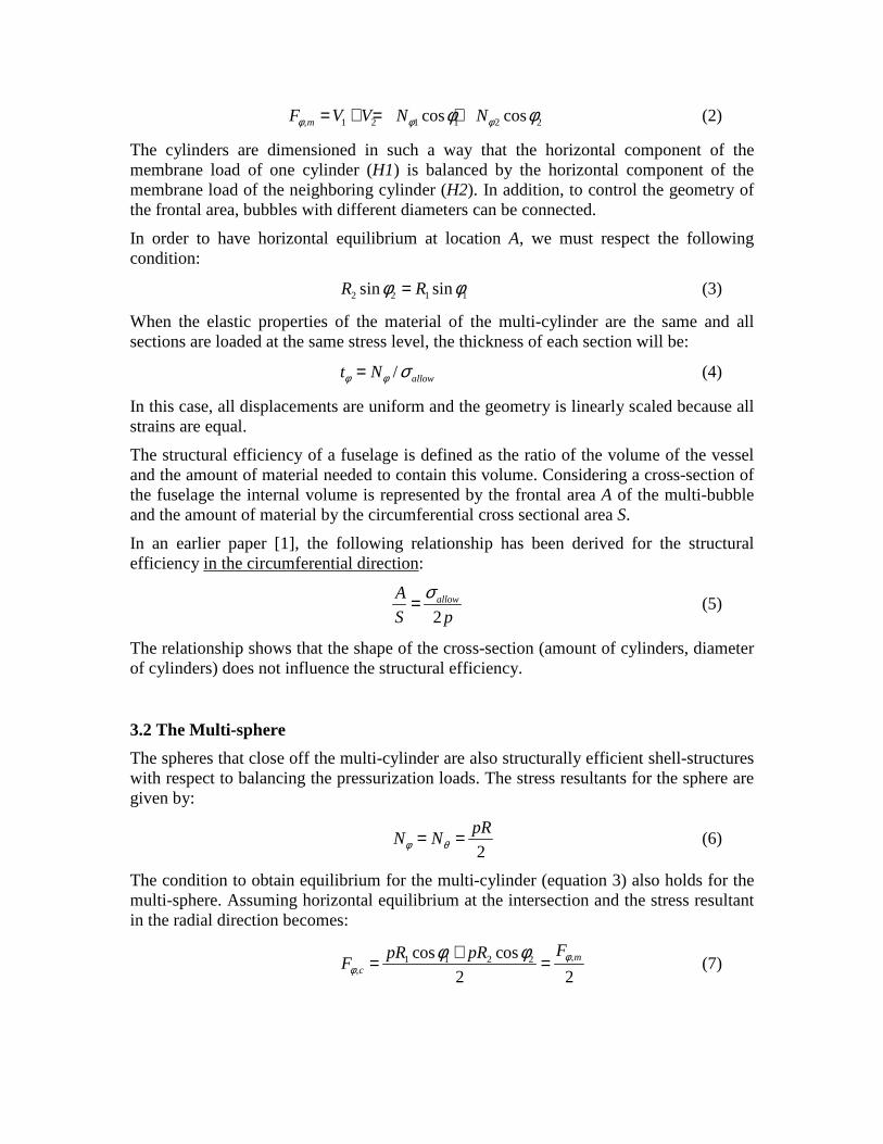
In the next section, it will be clear that the best way to transfer these loads into the structure is done via a reinforcement ring. (Figure 5)
The tensile loads in this ring are:
1 1 ,sin cT R Fφφ= (8)
Figure 5: Reinforcement ring multi-sphere
3.3 The Multi-torus
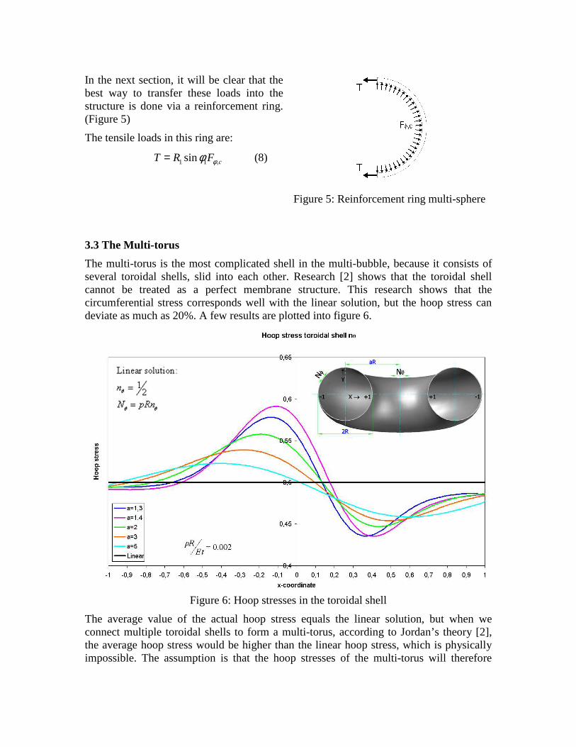
The multi-torus is the most complicated shell in the multi-bubble, because it consists of several toroidal shells, slid into each other. Research [2] shows that the toroidal shell cannot be treated as a perfect membrane structure. This research shows that the circumferential stress corresponds well with the linear solution, but the hoop stress can deviate as much as 20%. A few results are plotted into figure 6.
Figure 6: Hoop stresses in the toroidal shell
The average value of the actual hoop stress equals the linear solution, but when we connect multiple toroidal shells to form a multi-torus, according to Jordan’s theory [2], the average hoop stress would be higher than the linear hoop stress, which is physically impossible. The assumption is that the hoop stresses of the multi-torus will therefore
deviate less from the linear solution as compared to the deviation with the separate toroidal shells. Experimental investigation still needs to confirm this assumption.
Another issue which is present in the multi-torus is that the multiple connected toroidal shells are not in equilibrium with each other. The horizontal equilibrium condition which is valid for the multi-cylinder (equation 3), leads to a mismatch in horizontal equilibrium for the toroidal bulkhead (figure 7).
The circumferential stresses in the toroidal shell are defined as [3]:
2 sin
2 sin
pR aR RN
aR Rφφ
φ += +
(9)
The mismatch is given by (notation of figure 4):
1 1 1 1 1 1 2 2 2 2 2 2
1 1 1 1 2 2 2 2
cos( ) 2 sin cos( ) 2 sin
2 sin 2 sin
pR R a R pR R a Rh
R a R R a R
φ φ φ φφ φ
+ += −+ +
(10)
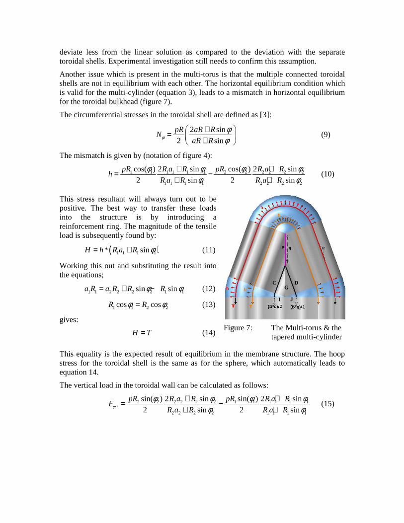
This stress resultant will always turn out to be positive. The best way to transfer these loads into the structure is by introducing a reinforcement ring. The magnitude of the tensile load is subsequently found by:
( )1 1 1 1* sinH h R a R φ= + (11)
Working this out and substituting the result into the equations;
1 1 2 2 2 2 1 1sin sina R a R R Rφ φ= + − (12)
1 1 2 2cos cosR Rφ φ= (13)
gives:
H T= (14)
Figure 7: The Multi-torus & the tapered multi-cylinder
This equality is the expected result of equilibrium in the membrane structure. The hoop stress for the toroidal shell is the same as for the sphere, which automatically leads to equation 14.
The vertical load in the toroidal wall can be calculated as follows:
2 2 2 2 2 2 1 1 1 1 1 1,
2 2 2 2 1 1 1 1
sin( ) 2 sin sin( ) 2 sin
2 sin 2 sint
pR R a R pR R a RF
R a R R a Rφφ φ φ φ
φ φ+ += −
+ + (15)
G
I J
C D
3.4 The tapered multi-cylinder
The multi-bubble in the front-section is tapered and at the intersection where the multi-bubble joins (figure 3), an additional reinforcement is needed to carry the tensile load that is caused by the taper.
The distributed load is defined as (figure 7):
12 sin sinq pR φ α= (16)
The total load Q, which is q B× , is then distributed via the supports C & D. The length B is:
cos
sin
RB
φα
= (17)
Hence, 212 sin cos 2Q pR Tφ φ= = (18)
Again, the equality is obvious. Furthermore, a similar analysis shows that the axial load induced by the triangular membrane G and the toroidal sections I & J (figure 7) is indeed counteracted by the sphere located in the middle of the multi-sphere.
3.5 Discussion
For pressurized vessels, the principal stresses are the stresses working in the circumferential and hoop or axial direction. This means that structurally, the best material is a fiber reinforced material with the fibers oriented in the principal stress direction, or an angle-ply with the fibers oriented according to the magnitude of the principal stresses.
The total structural efficiency κ (section 3.1) (axial stress incorporated) of an optimized isotensoid pressure vessel is [4]:
3allow
p
σκ = (19)
If we analyze the theoretical structural efficiency of the multi-bubble, we can also conclude that equation 19 is also valid for the multi-bubble. This relationship is not valid when use is made of isotropic materials. The other advantage of the application of fiber reinforced composites is that there are no discontinuities in the displacements at the junctions of the different membrane elements. Although the use of composites changes the manufacturing, it simplifies the design.
4 PRESSURE CABINS: MULTI-BUBBLE INTEGRATION WITH THE AIRFRAME
4.1 Background
In section 3, the analysis of the closed cell multi-bubble for Blended Wing Bodies was explained and the structural potential of this multi-bubble was shown in section 3.5. The closed cells of the multi-bubble as described in the previous section are however not usable for passenger transport. For passenger transport, an open structure needs to be created (for passenger acceptance and evacuation) and windows and doors need to be incorporated. The cut-outs for doors and windows are placed in the outer bubble and in the multi-sphere. The structural design of these cut-outs will be future research. To create an open structure, walls need to be transformed into pillars. A promising concept is shown in figure 2 and it is therefore used here for analyzing different options of load transfer. The walls are reduced to pillars, and are connected to axial stiffeners/beams that (partly) protect the aerodynamic shell against buckling. The floor floats in the cabin and is attached to the pillars. Pillars are however detrimental to the structural efficiency and from an engineering point of view, it is important to reduce the pillar-pitch as much as possible. A preliminary analysis to estimate the order of magnitude of the weight-increase is provided in section 4.2. In section 4.3, different options are distinguished for the integration of the multi-bubble with the aerodynamic shell.
4.2. Stiffener-pillar analysis
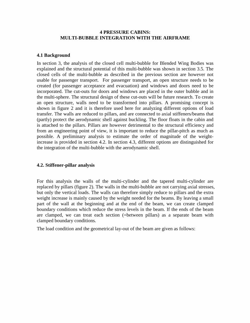
For this analysis the walls of the multi-cylinder and the tapered multi-cylinder are replaced by pillars (figure 2). The walls in the multi-bubble are not carrying axial stresses, but only the vertical loads. The walls can therefore simply reduce to pillars and the extra weight increase is mainly caused by the weight needed for the beams. By leaving a small part of the wall at the beginning and at the end of the beam, we can create clamped boundary conditions which reduce the stress levels in the beam. If the ends of the beam are clamped, we can treat each section (=between pillars) as a separate beam with clamped boundary conditions.
The load condition and the geometrical lay-out of the beam are given as follows:
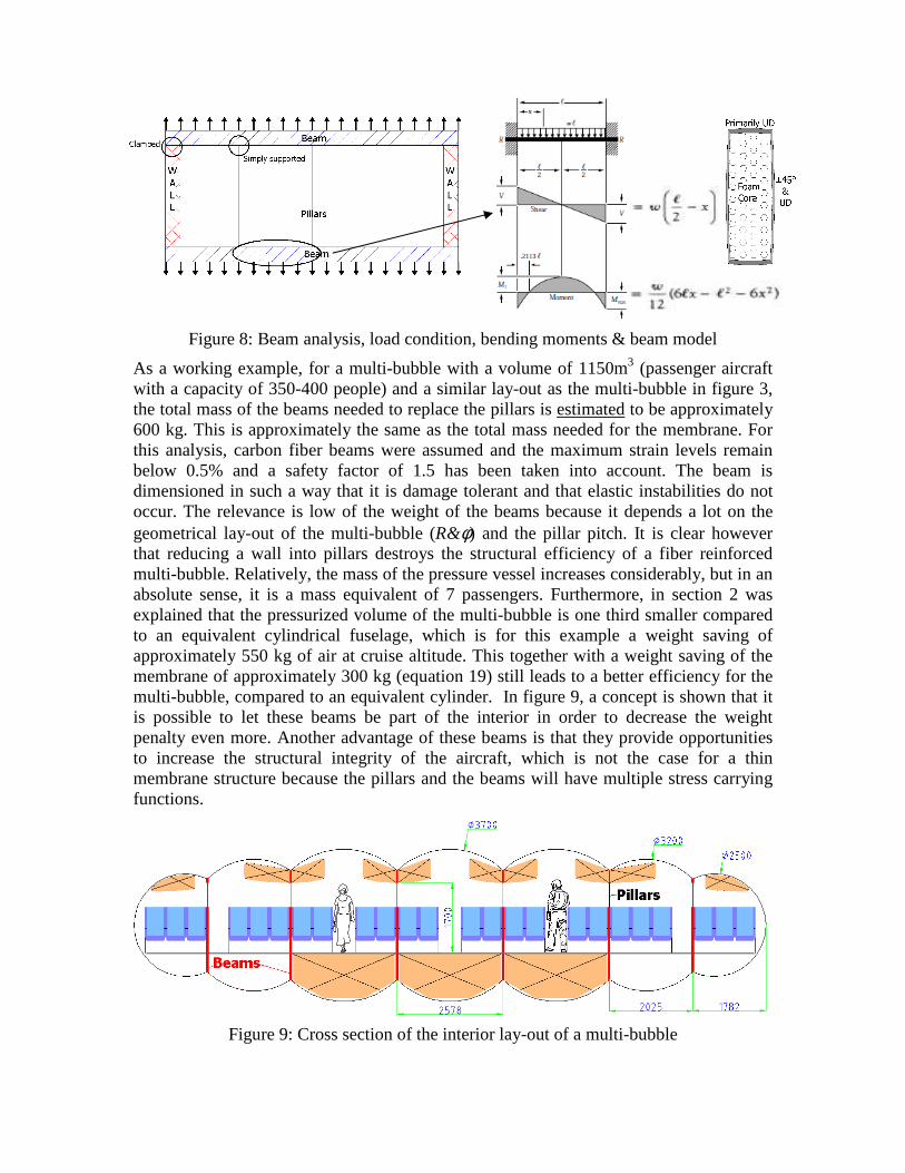
Figure 8: Beam analysis, load condition, bending moments & beam model
As a working example, for a multi-bubble with a volume of 1150m3 (passenger aircraft with a capacity of 350-400 people) and a similar lay-out as the multi-bubble in figure 3, the total mass of the beams needed to replace the pillars is estimated to be approximately 600 kg. This is approximately the same as the total mass needed for the membrane. For this analysis, carbon fiber beams were assumed and the maximum strain levels remain below 0.5% and a safety factor of 1.5 has been taken into account. The beam is dimensioned in such a way that it is damage tolerant and that elastic instabilities do not occur. The relevance is low of the weight of the beams because it depends a lot on the geometrical lay-out of the multi-bubble (R&φ) and the pillar pitch. It is clear however that reducing a wall into pillars destroys the structural efficiency of a fiber reinforced multi-bubble. Relatively, the mass of the pressure vessel increases considerably, but in an absolute sense, it is a mass equivalent of 7 passengers. Furthermore, in section 2 was explained that the pressurized volume of the multi-bubble is one third smaller compared to an equivalent cylindrical fuselage, which is for this example a weight saving of approximately 550 kg of air at cruise altitude. This together with a weight saving of the membrane of approximately 300 kg (equation 19) still leads to a better efficiency for the multi-bubble, compared to an equivalent cylinder. In figure 9, a concept is shown that it is possible to let these beams be part of the interior in order to decrease the weight penalty even more. Another advantage of these beams is that they provide opportunities to increase the structural integrity of the aircraft, which is not the case for a thin membrane structure because the pillars and the beams will have multiple stress carrying functions.
Figure 9: Cross section of the interior lay-out of a multi-bubble
4.3 Multi-bubble integration
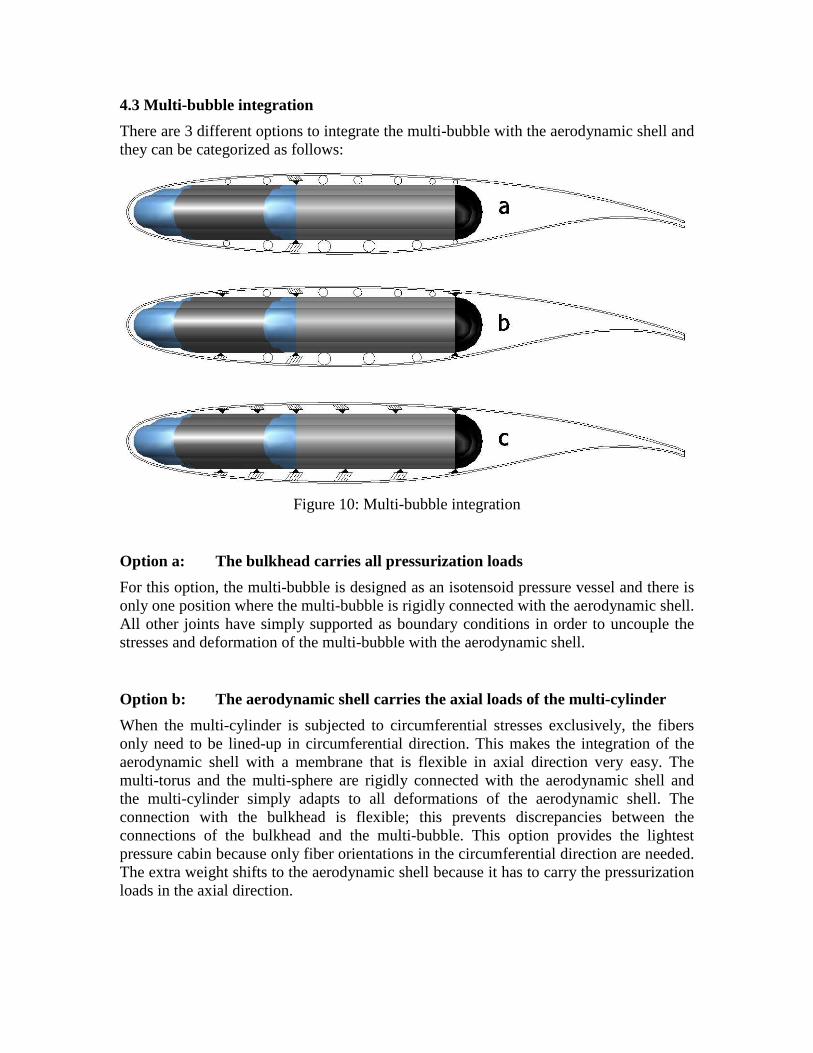
There are 3 different options to integrate the multi-bubble with the aerodynamic shell and they can be categorized as follows:
Figure 10: Multi-bubble integration
Option a: The bulkhead carries all pressurization loads
For this option, the multi-bubble is designed as an isotensoid pressure vessel and there is only one position where the multi-bubble is rigidly connected with the aerodynamic shell. All other joints have simply supported as boundary conditions in order to uncouple the stresses and deformation of the multi-bubble with the aerodynamic shell.
Option b: The aerodynamic shell carries the axial loads of the multi-cylinder
When the multi-cylinder is subjected to circumferential stresses exclusively, the fibers only need to be lined-up in circumferential direction. This makes the integration of the aerodynamic shell with a membrane that is flexible in axial direction very easy. The multi-torus and the multi-sphere are rigidly connected with the aerodynamic shell and the multi-cylinder simply adapts to all deformations of the aerodynamic shell. The connection with the bulkhead is flexible; this prevents discrepancies between the connections of the bulkhead and the multi-bubble. This option provides the lightest pressure cabin because only fiber orientations in the circumferential direction are needed. The extra weight shifts to the aerodynamic shell because it has to carry the pressurization loads in the axial direction.
Option c: The pressure cabin carries all pressurization loads but does not deform in axial direction
A very interesting option is to have a pressure cabin that fully resists the pressurization loads and still preserve structural integrity by integrating the pressure cabin rigidly with the aerodynamic shell. This can be done by selecting an angle ply that contracts in such a way that the axial displacements of the multi-bubble in the flexible membrane are eliminated due to the circumferential displacements of the multi-bubble. (Poisson effect)
In an earlier paper [1], the following relationship was derived for the fiber angle of this angle-ply:
( )1atan 2
2A B C D
Aφ = ± ⋅ + +
(20)
( )( ) ( ) ( )
( )
22 12
12 66 11 22 66
2 22 2 266 12 66 12 11 22
66 11 22 11 22 12 22 11
Where A, B and C are defined as:
2 4 4
16 1 16 4 1
8 2 4
A s Rs
B s s R s s s
C s R s s s R Rs Rs
D Rs Rs Rs s s s s s
= − += + + − − +
= + + + − + +
= − + + + − −
Of which the terms sij are terms of the stiffness matrix S:
11 12 16
12 22 26
16 26 66
s s s
S s s s
s s s
=
And R is defined as the x
NR
Nφ=
For every fiber reinforced material with a known stiffness matrix, it is possible to find an angle-ply for different R values. The range of R-values in this application is between 1 and 2. The results for a material with a given stiffness matrix are shown in figure 10.
The admissible strain of the material can be calculated as follows:
11cos cosallow
N
Aφ φε
εφ φ
= = (21)
Angle-ply for zero axial displacements
0
10
20
30
40
50
60
1 1,1 1,2 1,3 1,4 1,5 1,6 1,7 1,8 1,9 2
R=Nφφφφ/Nx
Ang
le (
± de
gree
s)
Figure 11: Angle-ply determination for zero-displacement
This equation is only valid when the aerodynamic shell or the connection with it is flexible enough so that it is allowed to assume that the aerodynamic shell doesn’t take up the pressurization load. The other important aspect about this option is that the loads induced by the reinforcements needed at the intersections of the multi-sphere and the multi-torus have to be distributed over the multi-torus and the multi-sphere in such a way that there is a uniform axial load working on the multi-cylinder. The multi-bubble is in this case not an isotensoid structure anymore; this has a negative influence on the structural efficiency.
CONCLUSION
This paper provides an outline of the analysis of the multi-bubble and it is shown that the multi-bubble can be designed into an isotensoid pressure vessel. This paper also shows that a segregated multi-bubble connected into an aerodynamic shell is a potential solution as a future pressure fuselage for Blended Wing Bodies.
REFERENCES
[1] Geuskens F.J.J.M.M., “Non-Cylindrical composite pressure fuselages for future aircraft” , ASC-Conference 2008
[2] P.F. Jordan,”Stresses and deformations of the thin-walled torus” J. Aerospace Sci. 29, 213 (1962)
[3] Geuskens, F.J.J.M.M., “Analysis and Design of Composite plates and Shells, a practical handbook for engineers”, Graduation report, Delft, May 2007
[4] V.V. Vasiliev, A.A. Krikanov, A.F. Razin, New generation of filament-wound composite pressure vessels for commercial applications, Composite streuctres, Volume 62, Issues 3-4, pages 449-459, 2003