Embed Size (px)
Citation preview

PRESSURIZED SOLUTION DISTRIBUTION SYSTEM (PSDS)
Operation and Maintenance Manual
3026685 REV E 20Mar12


3026685 Rev E A 20Mar12
PRESSURIZED SOLUTION DISTRIBUTION SYSTEM
(PSDS)
Operation and Maintenance Manual
TABLE OF CONTENTS
Page
CHAPTER ONE: GENERAL INFORMATION 1-1
Section 1.1 The Manual 1-3
1.2 Safety Summary 1-3
1.3 Applications 1-4
1.4 Contraindications 1-4
1.5 Environmental Considerations 1-5
1.6 Theory of Operation 1-6
1.7 Fluid Components 1-6
1.8 Monitors and Controls 1-8
1.9 Alarms 1-10
1.10 Options 1-11
1.11 Specifications 1-13
1.12 Disposal 1-14
1.13 Electromagnetic Interference 1-14
1.14 Service Assistance 1-14
1.15 Return Materials Authorization (RMA) Procedure 1-15
1.16 Symbols and Abbreviations 1-16
CHAPTER TWO: INSTALLATION GUIDELINES AND
INSTRUCTIONS
2-1
Section 2.1 Installation Guidelines 2-3
2.2 PSDS Installation Requirements 2-3
2.3 Distribution Loop Installation Requirements 2-4
2.4 Patient Station Instructions 2-4
2.5 Installation Instructions 2-5
2.6 Bicarb Distribution Loop Connections 2-6
2.7 Acid Pump Controller Connections 2-7
2.8 Acid Distribution Loop Connections 2-9
2.9 PSDS Status Monitor Installation 2-9

3026685 Rev E B 20Mar12
CHAPTER THREE: SYSTEM OPERATION 3-1
Section 3.1 Daily Start-Up 3-3
3.2 Acid Distribution Start-Up Procedure 3-3
3.3 Mix Tank Fill Procedure 3-4
3.4 Bicarb Solution Mix Procedure 3-5
3.5 Bicarb Solution Transfer Procedure 3-6
3.6 Bicarb Solution Distribution Procedure 3-7
3.7 Bicarb Distribution Tank & Loop Drain Procedure 3-8
3.8 PSDS Rinse Procedure 3-12
3.9 PSDS Disinfection/De-Calcifying Procedure 3-15
3.10 PSDS Status Monitor 3-21
CHAPTER FOUR: ROUTINE MAINTENANCE 4-1
Section 4.1 Routine Maintenance of Solution Distribution System
4-3
4.2 Specific Maintenance Procedures and Instructions
4-6
4.2.1 Bicarb System Disinfection or De-calcification Procedure
4-6
4.2.2 Recommended Bacterial Monitoring Procedure 4-6
4.2.3 Leak Repair 4-7
4.2.4 Bicarb Mix Pump Maintenance 4-9
4.2.5 PSDS Status Monitor Maintenance 4-11

3026685 Rev E C 20Mar12
CHAPTER FIVE: TROUBLESHOOTING 5-1
Table of Contents 5-3
Section 5.1 Alarm System 5-5
5.2 Auto-Fill Mode Time Pre-set 5-12
5.3 The Bicarb Mixing System 5-12
5.4 Distribution Loop Problems (Acid/Bicarb) 5-15
5.5 Leaks 5-15
5.6 Rinse Pump 5-16
5.7 Main Power Switch 5-16
5.8 Programmable Logic Controller (PLC) 5-17
5.9 Inlet Solenoid Valve 5-18
CHAPTER SIX: DRAWINGS 6-1
CHAPTER SEVEN: SPARE PARTS LIST 7-1
APPENDIX A: TECHNOTES/LOG SHEETS

Pressurized Solution Distribution System
3026685 Rev E D 20Mar12
This page intentionally left blank.

Pressurized Solution Distribution System
3026685 Rev E 1 - 1 General Information
Pressurized Solution Distribution System
PSDS
CHAPTER ONE:
GENERAL INFORMATION

Pressurized Solution Distribution System
3026685 Rev E 1 - 2 General Information
This page intentionally left blank.

Pressurized Solution Distribution System
3026685 Rev E 1 - 3 General Information
1.1 The Manual
This manual has been prepared to provide the operator with information and instructions regarding the installation, use, maintenance, and troubleshooting of the Mar Cor Purification Pressurized Solution Distribution System (PSDS).
CAUTION: When used as a medical device, Federal law restricts this device to sale by or on the order of a physician. Per CFR 801.109 (b)(1).
The manual has been written in narrative form supplemented with schematics and drawings for clarification. The operator can perform most procedures mentioned in this manual. Any exceptions will be clearly identified by a qualifying statement.
1.2 Safety Summary
Words in BOLD CAPITAL letters are used to identify key safety or qualifying statements. A list of all symbols and abbreviations is located at the end of this chapter.
This safety summary does not contain all of the safety statements in the manual. Other safety statements are included within the manual text and are enhanced and defined as follows:
WARNING: Statements identifying conditions or practices that could result in personal injury or loss of life.
CAUTION: Statements identifying conditions or practices that could result in equipment or other property damage.
NOTE: Statements that provide further clarification.
READ THIS MANUAL: Prior to operating or servicing this device, this manual must be read and understood. Keep this and other associated manuals for future reference and for new operators or qualified service personnel. A note sheet is provided at the end of each chapter for operators to make notations that may be valuable to other users.
USE PROPER POWER CONNECTIONS: Use proper wiring and connection methods to satisfy hospital electrical codes.

Pressurized Solution Distribution System
3026685 Rev E 1 - 4 General Information
DO NOT REMOVE COVERS OR PANELS: To avoid electrical shock hazard, do not remove covers or panels when power is supplied to the device. Do not operate the device when covers or panels are removed.
SHOCK HAZARD: Connect this device to a proper ground connection in accordance with the National Electrical Code. DO NOT under any circumstances remove the ground wire or ground prong from any power plug. DO NOT use an extension cord with this equipment.
DEVICE LABELING: Do not, under any circumstances, remove any Caution, Warning or any other descriptive labels from the devices until the conditions warranting the label are eliminated.
TRANSPORTING: When lifting or carrying the PSDS unit use at least 4 persons or properly rated lifting equipment. Ensure all proper safety equipment is used when moving the PSDS.
DO NOT OPERATE IN A FLAMMABLE ATMOSPHERE: To avoid fire or explosion, do not operate this device in an explosive environment or near flammable anesthetics.
1.3 Applications
The Pressurized Solution Distribution System (PSDS) is to be used in a hemodialysis facility for mixing and distribution of sodium bicarbonate solution and the distribution of acid concentrate solution to remote points of use where they are used in hemodialysis.
WARNING: The PSDS is not equipped with solution monitoring devices for conductivity, pH, or other chemically founded parameters. The operator is responsible for following the testing recommendations of the solution, chemical, or product manufacturer.
NOTE: The PSDS is a solution distribution system and does not perform proportioning functions.
CAUTION: If the PSDS is used in a manner not specified by the manufacturer the protective features of the unit might be impaired.
1.4 Contraindications
The Pressurized Solution Distribution System is not designed, sold, or intended to be used outside of the device specifications and limitations, as outlined in this manual and other related materials.

Pressurized Solution Distribution System
3026685 Rev E 1 - 5 General Information
1.5 Environmental Considerations
Prior to the installation of your PSDS, it will be necessary to provide utilities and create an environment suitable for the trouble free operation. Performance will be affected by compliance.
POWER: The PSDS operates on 115V single-phase power. Histories of power failure, power surges, and low line voltages should be noted and reported to the manufacturer or their agent as they may create adverse conditions for the operation of equipment. A backup power source or line conditioner may be required for uninterrupted operation.
DRAIN: The PSDS requires a drain outlet. The drain must have a minimum capacity of twenty gallons per minute of continuous flow. The maximum height for the drain is six inches. The PSDS drain(s) should be routed separately from other equipment to a drain.
TEMPERATURE: The PSDS should be located in an environment that will protect it from freezing or excessive heat.
NOISE: It is advisable to locate the system away from the patient area. Hard walls will reflect noise and may make the unit seem louder.
WATER: The PSDS requires water that meets AAMI or local hemodialysis water quality standards. Additionally, it is necessary to have adequate flow rates and pressures. The minimum flow rate required for operation of the PSDS is ½ gallon per minute.
The supplied water temperature affects the bicarbonate mixing ability. Follow the bicarbonate manufacturer‟s recommendations for preferred water temperature.
NOTE: Three to five gallons per minute flow rate is recommended. Lower flow rates will prolong the filling, rinsing and disinfection procedures of the mix and distribution tanks.
NOTE: Low water temperature may cause difficulty in mixing and/or will result in extended mixing times.

Pressurized Solution Distribution System
3026685 Rev E 1 - 6 General Information
1.6 Theory of Operation
The Pressurized Solution Distribution System (PSDS) provides semi-automatic mixing of a bicarbonate concentrate powder with supplied AAMI quality water and distributes this solution along with up to three acid concentrates, depending on the model, to hemodialysis patient stations.
The bicarbonate solution is thoroughly mixed in a mix tank before being transferred to a distribution tank for circulation through the distribution loop. The distribution and mix tanks, pumps, plumbing, and controls are connected or located next to the PSDS frame.
The operational pressure in the distribution loop must not be allowed to exceed the dialysis machine manufacturer‟s maximum pressure, therefore Mar Cor recommends the use of pressure regulation at each point of use to prevent these issues. The PSDS is available in models that can control the distribution of acid concentrate from a bulk storage tank to remote points of use. The acid distribution pumps are located near the bulk tanks with controls centralized on the PSDS frame.
1.7 Fluid Components
Inlet Solenoid Valve The inlet solenoid valve serves to control the supply of water to the mix tank and rinsing procedure.
Flow Meter The flow meter includes an integral needle valve to provide visual flow rate indication and adjustment.
Mix Tank The mix tank is a high purity polyethylene tank with a conical shaped bottom and molded volume markings. The mix tank includes the following components:
The mix tank is equipped with a spray head for rinsing and disinfecting internal surfaces.
A sampling port is located at the bottom of the mix tank for testing/sampling purposes.
A hinged cover is provided on top of the mix tank for easy access.
An eductor (mix nozzle) is located at the bottom of the mix tank to aid in mixing.
A carbon vent filter connected to the top of the mix (and distribution) tanks inhibits dust or other debris from entering.
Drains Two drain valves are provided to allow discharge of unused solution or rinse water. There is one drain on each of the mix and distribution tanks.

Pressurized Solution Distribution System
3026685 Rev E 1 - 7 General Information
Mix Pump The mix pump provides for mixing of the bicarbonate powder into solution and transfer of the mixed solution from the mix tank to the distribution tank. The mix pump is controlled with a timer that will shutdown the pump after 10 minutes of operation to minimize the potential of over mixing. If more than 10 minutes of mixing is required the hand switch will need to be turned to OFF and back to MIX to resume mixing.
Flow Switch A flow switch is located on the output side of the mix pump. The flow switch prevents damage to the mix pump by automatically turning the mix pump off during insufficient flow situations. An audible alarm will also sound.
Distribution Tank The distribution tank is a high purity polyethylene tank with a conical shaped bottom and molded volume markings. The distribution tank includes the following components:
The distribution tank includes float switches to communicate the high-level and low-level conditions to the PSDS controls.
The distribution tank is equipped with a spray head for rinsing and disinfecting internal surfaces.
A jug fill valve is located near the bottom of the distribution tank for filling containers with mixed bicarbonate solution.
A hinged cover is provided on top of the distribution tank for easy access.
A carbon vent filter connected to the top of the distribution (and mix) tanks inhibits dust or other debris from entering.
A valve is located near the return of the distribution loop to allow sampling of actual loop conditions.
Distribution Pump The distribution pump(s) provide for delivery of the bicarbonate and acid solutions from the distribution tank or bulk acid tank(s) into and throughout the distribution loop. Mar Cor recommends that over pressure protection is installed at each use point.

Pressurized Solution Distribution System
3026685 Rev E 1 - 8 General Information
1.8 Monitors and Controls
Main Power Switch The Main Power switch is located on the front of the control panel and must be turned to the ON position to operate the PSDS.
Mix Pump Switch The Mix Pump switch is a three-position switch that controls power to the mix/transfer pump. With the switch in the TRANSFER position, the distribution tank high-level alarm and mix tank low flow alarms are both engaged and either can stop the pump operation.
Auto Fill Mode Timer The Auto Fill Mode timer is used along with the Mix Tank Auto Fill switch and inlet water solenoid to fill the mix tank for a predetermined amount of time. The timer mode must be set to “E” and “m” (minutes) with user adjustable time settings. The time setting will control the duration the inlet water solenoid opens to supply the mix tank with water.
Mix Tank Auto Fill Switch The Mix Tank Auto Fill switch is a momentary switch that initiates automatic or manual filling of the mix tank. When the switch is moved to the START position, the fill timer and solenoid are activated, filling the mix tank for the duration set by the timer. When the switch is held in the MANUAL position, the solenoid is activated, allowing water to flow into the mix tank as long as the switch remains held in this position.
Alarm Mute Switch The Alarm Mute switch is a push button switch that when pressed will silence the audible alarm. The alarm will not sound again if the alarm condition is removed during this period with the exception of the Distribution Tank Low Level alarm that does require the resetting of the Distribution Tank Low Level hand switch.
Auto Fill Flow Meter The flow meter scale allows visual setting between 0.5 and 5.0 GPM. The Auto Fill flow meter includes an integral needle valve to provide visual flow rate indication and adjustment.
Programmable Logic Controller (PLC) The programmable logic controller (PLC) is an input/output logic device that does not perform any calculations. Software is loaded into the PLC during the assembly and does not require operator interface once installed. The PLC continuously senses for inputs from hand switches, float switches, and the mix pump flow switch. PLC outputs control operation of the mix pump, auto fill timer, and audible alarms.

Pressurized Solution Distribution System
3026685 Rev E 1 - 9 General Information
Distribution Tank Low Level Alarm Switch The Distribution Tank Low Level Alarm hand switch controls the function of the distribution tank low-level alarm. The alarm is enabled when the switch is in the ON position. Moving the switch to the BYPASS/RESET position disables the alarm and illuminates the switch to provide additional user awareness of the alarm bypass.
Distribution Pump Switch The Distribution Pump switch is a two-position switch that controls power to the distribution pump. Moving the Distribution Pump switch to the ON position initiates operation of the Distribution pump and illuminates the Distribution Pump Run light.
Acid Tank Pump Switch The Acid Tank Pump switch is a two-position switch that controls power to the acid tank pump. Moving the Acid Tank pump switch to the ON position initiates operation of the Acid Tank pump and illuminates the Acid Tank Pump Run light. Up to three acids can be operated.
Distribution Pump Run Light The green Distribution Pump Run light illuminates when the Distribution Pump hand switch is in the ON position.
Acid Tank Pump Run Light The green Acid Tank Pump Run light illuminates when the Acid Tank Pump hand switch is in the ON position.
Acid Tank Low Level Light The amber Acid Tank Low Level light illuminates when a low-level condition in the associated acid tank occurs.

Pressurized Solution Distribution System
3026685 Rev E 1 - 10 General Information
PSDS Status Monitor The PSDS Status Monitor is designed to notify personnel of the Pressurized Solution Distribution System (PSDS) operation status using a combination of visual lights and audible alarms. Monitoring logic and power are delivered from the PSDS controller through cable connections to the PSDS Status Monitor. Its compact size and optional mounting features allow it to be located near the dialysis area or nurses station. The PSDS Status Monitor is available in either an external surface mount housing or flush mount panel with a variety of monitored features that include distribution pump and distribution tank low level alarm status, acid tank levels, and alarm conditions.
1.9 Alarms
Distribution Tank High-Level Alarm A distribution tank high-level alarm condition is created when the solution level in the distribution tank rises to engage the high-level float switch. The Mix Pump hand switch must be in the TRANSFER position and the Distribution tank high-level float switch engaged to activate the alarm. The mix pump shuts off to prevent overfilling of the distribution tank.
The high-level condition is typically observed when the solution level in the distribution tank fills during transfer from the mix tank. This is a normal occurrence and can be expected after the initial daily transfer. An audible alarm sounds to prompt the user to reposition the Mix Pump hand switch and plumbing valves once transfer is stopped.
The alarm will be discontinued when the mix pump hand switch on the PSDS is turned to the OFF position.
Distribution Tank Low-Level Alarm A distribution tank low-level alarm condition is created when the solution level in the distribution tank drops and activates the low-level float switch. The Distribution Tank Low Level Alarm hand switch must be in the ON position and the distribution tank low-level float switch not satisfied to activate the alarm.
The low-level condition is typically observed when the solution level in the distribution tank falls during use at the end of the treatment day or prior to the initial daily batch transfer from the mix tank. An audible alarm sounds to prompt the user to recognize the low level condition and take steps to replenish the distribution tank solution levels and/or disable the alarm. This alarm sounds when there are approximately 20 gallons of solution left in the distribution tank.
When the Distribution Tank Low Level Alarm hand switch is turned to the RESET/BYPASS position, the alarm will be discontinued.

Pressurized Solution Distribution System
3026685 Rev E 1 - 11 General Information
Mix Pump Low Flow Alarm A mix pump low flow alarm condition is created when the solution velocity in the mix pump piping drops below 2 GPM as measured at the flow switch on the output side of the mix pump. The Mix Pump hand switch must be in either the TRANSFER or MIX position and the mix pump low flow switch not satisfied to activate the alarm. The mix pump shuts off in the absence of solution to prevent pump damage.
The low flow condition is typically observed when the solution level in the mix tank empties while being transferred to the distribution tank. This is a normal occurrence and can be expected upon the initial daily transfer. An audible alarm sounds to prompt the user to reposition the Mix Pump hand switch and plumbing valves once transfer is stopped.
When the mix pump hand switch on the PSDS is turned to the OFF position the alarm will be discontinued. The Alarm Mute pushbutton switch can be pressed to silence the audible alarm prior to switch and valve repositioning.
Alarm Mute Pressing the Alarm Mute switch will silence the audible alarm for a period of five minutes. The alarms will not sound again if the alarm condition is removed during this period with the exception of the Distribution Tank Low Level alarm that does require the resetting of the Distribution Tank Low Level hand switch.
1.10 Options
Number of Acids Multiple product options accommodate varying customer needs for distribution loop combinations including single bicarbonate and up to three acid solutions (1 Bicarb, 0 Acid; 1 Bicarb, 1 Acid; 1 Bicarb 2 Acid; and 1 Bicarb, 3 Acid).
Wall Stations Wall-mounted solution dispensers are capable of delivering up to three different concentrates and water as well as drain access. Process connections are configured to be compatible with dialysis manufacturer‟s equipment.
Bulk Acid Storage Larger tanks (165 – 1000 gallon) are available for on site bulk storage of acid.
Heat Disinfection (RO Water Loop): Heat disinfection only applies to the RO water inlet piping loop that feeds the PSDS unit. The PSDS system cannot be heat disinfected.
If the PSDS unit is equipped with PVC loop flow piping, then it is NOT heat disinfect compatible. The PSDS unit must be equipped with PVDF loop flow piping in order to have this option. When performing RO loop piping heat disinfection, close the RO supply water shut-off valve to the PSDS unit.
Pressurized Solution Distribution System
3026685 Rev E 1 - 12 General Information
WARNING: The piping components, internal to the unit, are not heat tolerant and cannot be heat disinfected. To disinfect the PSDS system, refer to Section 3.9, PSDS Disinfection/De-Calcifying Procedure.

Pressurized Solution Distribution System
3026685 Rev E 1 - 13 General Information
1.11 Specifications
1.11.1 Input Water Requirements
Minimum Maximum
Input flow Rate (AAMI quality water) 0.5 GPM 5.0 GPM
Temperature (water)* 10°C (50°F) 30°C (86°F)
pH (water) 3.0 11.0
Inlet Pressure 20 PSI 100 PSI
Drain Capacity 20 GPM N/A
Drain Height N/A 6 in. (0.15 m)
* Refer to the bicarbonate powder manufacturer‟s recommendation for water temperature.
1.11.2 Electrical Specifications
Voltage 115 V~
Hertz 60
Amps 20
Phase Single
1.11.3 Environmental Requirement
Minimum Maximum
Ambient Temperature 4°C (39°F) 32°C (90°F)
Storage Temperature 2°C (36°F) 32°C (90°F)
Altitude N/A 10,000 feet
NOTE: The user/operator should recognize that moisture can be caused by condensation and is not necessarily an equipment leak. This equipment will function in the presence of condensation.
1.11.4 Dimensions/Weight
PSDS* 58H x 110W x 48D
*Additional space is required for operator access and acid tank(s).
Max Operational Weight: 2050 lbs

Pressurized Solution Distribution System
3026685 Rev E 1 - 14 General Information
1.12 Disposal
Disposal of this product or parts must be carried out in accordance with local disposal codes.
1.13 Electromagnetic Interference
This equipment can generate, uses and can radiate radio frequency energy and, if not installed and used in accordance with these instructions, may cause harmful interference to other devices in the vicinity. However, there is no guarantee that interference will not occur in a particular installation. If this equipment does cause harmful interference with other devices, which can be determined by turning the equipment off and on, the user is encouraged to try to correct the interference by one or more of the following measures:
Reorient or relocate the receiving device.
Increase the separation between the equipment.
Connect the equipment into an outlet on a circuit different from that to which the other device(s) is connected.
Consult the field service technician or manufacturer for help.
1.14 Service Assistance
If service assistance is required, please take the following steps:
Consult the troubleshooting section of this manual (Chapter 5). If the problem cannot be identified and corrected by any of the procedures found in that section, then...
Contact your Facility Equipment Technician. If the technician is unable to help then…
Call Mar Cor Technical Support Department at (800) 633-3080. Technicians are available for all calls between 7:00 a.m. and 7:00 p.m. CST, Monday through Friday.
Technicians are also available at other times for emergency calls only*. Product consultants will be on hand to discuss the problem with you and endeavor to rectify it over the phone. If the problem appears to be of a more serious nature, you will be given instructions regarding the action to be taken. Prior to making the phone call, you must be prepared to answer two questions:
1. What unit do you have, i.e. Pressurized Solution Distribution System
2. What is the serial number of your unit?
SERIAL NUMBER: ______________________
In addition, for Non-Emergency issues, you may e-mail [email protected] and a Technician will respond generally within one working day.
*Emergency: A situation that has or could cause the shut down of a clinic during operating hours or that puts patients in increased jeopardy.

Pressurized Solution Distribution System
3026685 Rev E 1 - 15 General Information
1.15 Return Material Authorization (RMA) Procedure
If you wish to return goods for, warranty evaluation and/or credit please have your original sales order, invoice and device serial number available when you call Mar Cor. Call Mar Cor at (800) 633-3080 and request Technical Support. A representative will provide instructions and a return authorization number, which needs to be clearly written on the outside of the box used to ship your materials. All equipment must be shipped with the freight prepaid by the customer. Call our Customer Service Center with any questions or issues concerning freight claims and a representative will discuss your situation.
All materials to be returned must be rendered into a non-hazardous condition prior to shipping.
Pressurized Solution Distribution System
3026685 Rev E 1 - 16 General Information
1.16 Symbols and Abbreviations
~ Volts Alternating Current
AAMI Association for the Advancement of Medical Instrumentation
C Celsius
CSA Canadian Standards Association
CC Cubic Centimeters
cfu/mL Colony Forming Units per milliliter
EU Endotoxin Units
F Fahrenheit
FDA Food and Drug Administration
GPM Gallons Per Minute
HZ Hertz
LBS Pounds
LPM Liters Per Minute
mEq Milli equivalents
mg/L Milligrams Per Liter
mL Milliliters
MNPT Male National Pipe Thread
N/A Not Applicable
ng/mL Nanograms Per Milliliter
NPT National Pipe Thread
PLC Programmable Logic Controller
P/N Part Number
PPM Parts Per Million
PSDS Pressurized Solution Distribution System
PSI Pounds Per Square Inch
PVC Polyvinyl Chloride
QD Quick Disconnect
RO Reverse Osmosis
VAC or V~ Volts Alternating Current

Pressurized Solution Distribution System
3026685 Rev E 2 - 1 Installation Guidelines and Instructions
Pressurized Solution Distribution System
PSDS
CHAPTER 2: INSTALLATION GUIDELINES AND INSTRUCTIONS

Pressurized Solution Distribution System
3026685 Rev E 2 - 2 Installation Guidelines and Instructions
This page intentionally left blank.

Pressurized Solution Distribution System
3026685 Rev E 2 - 3 Installation Guidelines and Instructions
2.1 Installation Guidelines
This chapter provides basic guidelines for the installation of the PSDS. Each application/installation will have particular characteristics that require individual attention when planning the installation.
2.2 PSDS Installation Requirements
The Pressurized Solution Distribution System should be located close to the patient care area to minimize loop length. The equipment only footprint is 3 feet deep by
nine feet wide. An additional 48 depth for operating space in front of the equipment, 24” on at least one side, and at least 24” behind are recommended. The floor area supporting the equipment must be level for proper function.
2.2.1 Electrical Requirements
115 VAC, 20 AMP, 1 Phase, 60Hz, Straight Blade Plug GFI Protected Outlet
115 VAC, 20 AMP, 1 Phase, 60Hz, GFI Protected Duplex Electrical Outlet is required for the acid distribution option.
2.2.2 Water Supply
The PSDS requires water that meets AAMI or local hemodialysis water quality standards. Additionally, it is necessary to have adequate flow rates and pressures. The minimum flow rate required for operation of the PSDS is ½ gallon per minute.
The supplied water temperature affects the bicarbonate mixing ability. Follow the bicarbonate manufacturer‟s recommendations for preferred water temperature.
2.2.3 Drain (Floor Sink)
The PSDS requires a drain outlet with a minimum capacity of twenty gallons per minute (20 GPM) of continuous flow and a maximum drain height of six inches.
The PSDS drain(s) should be routed separately from other equipment to a drain.

Pressurized Solution Distribution System
3026685 Rev E 2 - 4 Installation Guidelines and Instructions
2.3 Distribution Loop Installation Requirements
Distribution loop tubing:
Material: Pipe or Hose, ¾” I.D.
Material: Polyethylene Tube, 5/8” O.D.
The recommended maximum number of patient stations per loop is 25 stations with a loop length not more than 600 feet. The PSDS can support a maximum of two loops.
The distribution loop starts at the distribution pump and is routed to the patient stations before returning to the distribution tank.
The distribution loop may be routed in the ceiling (or raceway) dropping down to the patient stations or under the floor, rising to the patient stations. The loop can be elevated to a maximum height of 15 feet from the pumps.
Distribution loop plumbing must be continuous (no in-line couplings in walls or ceiling). Breaks or splices in the loop should occur with tee fittings only at a patient station dispenser.
Distribution loop tubing must be installed with no kinks or pinched sections and should be installed straight (level) with appropriate restraints to prevent excessive sagging.
If the distribution loop is to pass through an unheated space, the tube/piping should be insulated to prevent freezing.
2.4 Patient Stations
Patient station installation needs will vary with the particular distribution loop material type used and the number of distribution loops. The distribution loops will utilize either ¾” ID pipe (or hosing), or 5/8” tubing, and require applicable connection hardware. Multiple distribution loops and the connections to the patient stations will require that each one is thoroughly labeled or otherwise properly identified.
The connection between the distribution loop and the patient stations should be as short as reasonably possible and must utilize FDA approved materials that are inert and compatible with disinfection methods. Mar Cor recommends that over pressure protection (pressure regulators) is installed at each use point.
Each application/installation will have particular characteristics that require individual attention during the installation.
Pressurized Solution Distribution System
3026685 Rev E 2 - 5 Installation Guidelines and Instructions
2.5 Installation Instructions
1. Locate the PSDS frame, mix tank, and distribution tank in a level location. The location must include a floor drain, good ventilation, a 20 amp 115 VAC 1 phase straight blade outlet, and a 20 amp 115 VAC duplex outlet if an acid distribution system is included. A water supply valve should be in reasonable proximity.
2. Clean any shipping debris from inside the mix tank and distribution tank.
3. Connect the mix tank and distribution tank assemblies to the PSDS frame.
a. Reference the PSDS Mix Tank To Frame Assembly and PSDS Distribution Tank To Frame Assembly illustrations in Chapter 6.
b. Ensure the tanks are sitting level on their stands and plumbing valves are accessible.
c. Connect the frame to both tanks at the matching unions and adapters. Make certain that the union O-rings are in place.
4. Assemble the drain manifold.
a. Reference the PSDS Drain Assembly illustration in Chapter 6.
b. Mount the drain manifold in a manner appropriate for the location.
c. The distribution loop drain connection should be constructed to allow ease of use. The bicarbonate distribution loop return will alternate routes between the drain and the distribution tank return via a three way- valve. A sample valve is included on the distribution loop return and should be positioned at an angle for gravity feed.
5. Tighten all electrical screws in the control box to 9 inch-pounds with the exception of the PLC and terminal block. The PLC terminal screws should be tightened to 5-inch pounds and the terminal block to 7 inch-pounds.
CAUTION:
Vibrations during shipping/operation may cause connections to loosen. Loose connections may not allow the PSDS to operate correctly.
6. Connect the distribution tank float switch wires to the PSDS controller.
a. Connect the distribution tank high-level float switch to terminal block segments COM and 4.
b. Connect the distribution tank low-level float switch to terminal block segments COM and 10.
7. Connect the inlet water supply.
a. For cold water, chemical disinfection; the unit includes two, 1 inch threaded female NPT ports for inlet and outlet RO water connections. For hot water, heat disinfection, the unit includes two ¾ inch threaded female NPT ports.

Pressurized Solution Distribution System
3026685 Rev E 2 - 6 Installation Guidelines and Instructions
Inlet and outlet connections are interchangeable at the unit. The inlet port is field connected from the loop supply feed. The outlet port is field connected to the loop return line.
8. Route the power cord to the appropriate electrical outlet.
9. Install the carbon filter for the mix and distribution tanks according to the instruction sheet in the carbon filter kit.
10. If necessary secure the tank stands to the floor. If local codes require seismic restraints use holes in the stand‟s feet to secure them to the floor.
2.6 Bicarb Distribution Loop Connections
Reference the Bicarb Distribution Loop Connections illustration in Chapter 6 for visual aid.
2.6.1 Bicarb Distribution Loop Supply Connection
1. Connect the start of the bicarbonate distribution loop to the pump outlet assembly.
a. The installation kit includes parts to ease connection of the loop supply and not all parts of this kit may be necessary if the loop is already constructed with flexible hosing.
b. If a flexible connection is required use several feet of ¾” hose, a couple of PVC nipples, hose clamps, and a ¾” union at the necessary length to connect the distribution pumps and loop supply.
2.6.2 Bicarb Distribution Loop Return Connection
1. Connect the end of the bicarbonate distribution loop to the 3-way return valve on the distribution tank.
a. The installation kit includes parts to ease connection of the loop return and not all parts of this kit may be necessary if the loop is already constructed with flexible hosing.
b. If a flexible connection is required, use several feet of ¾” hose, male and female quick disconnects, a PVC nipple, hose clamps, and a ¾” union at the necessary length to connect the distribution loop return and tank assembly.

Pressurized Solution Distribution System
3026685 Rev E 2 - 7 Installation Guidelines and Instructions
2.7 Acid Pump Controller Installation
Reference the PSDS wiring diagrams, P/N 1267220 and 3026597 for a visual description of wire connection locations.
NOTE: A filter and housing are provided to vent the acid tank.
2.7.1 Installation Considerations
1. Mount the Acid Pump Controller on a visible section of wall near the acid tanks and within a few feet of an 115VAC, 1 Phase, 20 Amp, GFI protected electrical outlet.
2. Connect the power cord only when all connections have been made and installation is complete.
3. Dimensions: Height – 11.5 inches; Width – 9.25 inches; Depth – 6 inches
2.7.2 PSDS Connections
1. Connect the 9 conductor cable and wiring to the PSDS Controller. Connect the fitting to the most convenient connection hole on the bottom of the controller and remove any hole plugs as necessary.
2. Connect the acid pump control wires to the PSDS controller terminal block. The number of wires is dependent on the acid controller type and not all of the following connections may be required.
a. Connect the white wire to terminal „24N‟. b. Connect the red wire to terminal „7‟. c. Connect the orange wire to terminal „8‟. d. Connect the yellow wire to terminal „9‟.
3. Connect the 9-conductor cable to the Acid Pump Controller. Route the cable along the PSDS frame and present cable path.
a. Cut the cable to fit the length required to position the acid pump controller as close to the acid tanks as necessary.
4. Connect the acid pump control wires to the acid pump controller terminal block 2 (A or B). The number of wires is dependent on the acid controller type and not all of the following connections may be required.
a. Connect the white wire to terminal TB2-4. b. Connect the red wire to terminal TB2-1 (Acid 1). c. Connect the orange wire to terminal TB2-2 (Acid 2). d. Connect the yellow wire to terminal TB2-3 (Acid 3).

Pressurized Solution Distribution System
3026685 Rev E 2 - 8 Installation Guidelines and Instructions
2.7.3 Acid Pump Connections
1. Depending on the number of acid pumps in the particular system, connect each set of 3 acid pump power supply wires to the respective points on the Acid Pump Controller.
a. Connect the black wire to terminal TB1-6, TB1-7, or TB1-8 (acid 1, 2 and 3 respectively).
b. Connect the white wire to terminal TB1-3, TB1-4, or TB1-5 (acid 1, 2 and 3 respectively).
c. Connect the green wire to the ground terminal on the controller chassis.
2. Select a location for the acid pumps between the bulk tanks and the acid pump controller. Mount the acid pumps on the stands using the hardware provided. Mount the acid pump stands on the floor using the washers and hardware provided.
3. Connect the acid pump power supply wires to the acid pump motor. a. Connect the two black, two white, and two green wires together.
2.7.4 Acid Tank Float Switch Connections
1. Install the acid tank low-level float switch in the normally closed position on the side of the storage tank (closed when empty).
NOTE: The acid tank low-level float switch is normally located at the 75 to 100 gallon level. This should be discussed with the facilities Chief Technician or a representative to determine the gallon level to install the float switch.
2. Connect each pair of acid tank float switch connection wires to the PSDS Controller as shown in the system-wiring diagram in drawings P/N 1267220 and 3026597.
a. The installation kit includes cable and wire ties to connect the float switch wire leads to the PSDS Controller. From Acid Pump Controller To PSDS Controller
Black TB2- 5 Low Level Tank 1
Black TB1-13 Black TB2- 7 Low Level Tank 2
Black TB2- 9 Low Level Tank 3
Blue TB2- 6 Low Level Tank 1 Blue TB1-19
Violet TB2- 8 Low Level Tank 2 Violet TB1-20
Brown TB2- 10 Low Level Tank 3 Brown TB1-21
Red TB2-1 ADP1 TB1-7
Orange TB2-1 ADP2 TB1-8
Yellow TB2-3 ADP3 TB1-9
White TB2-4 24N TB1-24N

Pressurized Solution Distribution System
3026685 Rev E 2 - 9 Installation Guidelines and Instructions
2.8 Acid Distribution Loop Connections
Reference the Acid Distribution Loop Connections illustration in Chapter 6 for visual aid.
2.8.1 Acid Distribution Loop Supply Connections
1. Connect the start of the acid distribution loop to the union on the acid distribution pump outlet assembly.
a. The installation kit includes parts to ease connection of the loop supply and not all parts of this kit may be necessary if the loop is already constructed with flexible hosing.
b. If a flexible connection is required use several feet of ¾” hose, a couple of polypropylene nipples, hose clamps, and a ¾” union at the necessary length to connect the acid distribution pump and loop supply.
2.8.2 Acid Distribution Loop Return Connections
1. Connect the end of the acid distribution loop to the return valve on the acid distribution tank.
a. The installation kit includes parts to ease connection of the loop return and not all parts of this kit may be necessary if the loop is already constructed with flexible hosing.
b. If a flexible connection is required; use several feet of ¾” hose, male and female quick disconnects, a polypropylene nipple, hose clamps, and a ¾” union at the necessary length to connect the distribution loop return and tank assembly.
2.9 PSDS Status Monitor Installation
Reference the PSDS wiring diagram in Chapter 6 for a visual description of wire connection locations.

Pressurized Solution Distribution System
3026685 Rev E 2 - 10 Installation Guidelines and Instructions
2.9.1 Installation Considerations
1. Operation of the PSDS Status Monitor is dependent on the proper connections and correct functioning of the connected devices. These devices may include the distribution tank level switches, acid tank level switches, mix pump flow switch, and the PSDS controller itself.
2. Approximate Dimensions: Height – 4”, Width – 8”, Depth – 3”
3. Mount the PSDS Status Monitor in a location with consideration for the effectiveness of sight and sound paths.
a. The PSDS Status Monitor is available in either a Surface Mount or Flush Mount model. The Surface Mount model mounts to the wall using slots included on the enclosure. The Flush Mount model mounts to the wall inside a 4-gang junction box.
4. The PSDS Status Monitor is directly connected to the PSDS controller through two cables. The connection cables include specific insulation color-coding requirements to correctly associate installation connections.
a. For cable connections use Belden brand part number 8465 (5 Conductor), and Belden brand part number 8489 (4 Conductor), or their direct equivalents.
Suggested cable vendor part numbers are supplied as follows:
PSDS Cable Connection Suggested Vendor Part Number
5-Conductor Cable Belden Part Number 8465
4-Conductor Cable Belden Part Number 8489
2.9.2 Installation Procedures
1. Make wiring connections from the PSDS Status Monitor to the PSDS controller. Remove the cable jacketing as necessary.
a. Use the butt splice connectors on the PSDS Status Monitor to connect to the individual cables conductors. Ensure that there are no conductors visible after full tightening.
NOTE: The 4-conductor cable will carry 24VDC signal and must be connected to the Alarm Mute switch and Distribution Tank Low Level Alarm indicator connectors.
Wiring routed from the PSDS unit to the remote monitor must meet local codes for 24V installations. Wire length should not exceed 1,000 feet.

Pressurized Solution Distribution System
3026685 Rev E 2 - 11 Installation Guidelines and Instructions
b. Connect the color-coded cable conductors inside the PSDS controller to their associated terminal block locations. Strip the conductor insulation for approximately ¼” to ensure a solid connection. If using the cables suggested earlier in this manual, the wire colors will match up with the wires in the monitor.
PSDS
Terminal
Color Function Monitor
Connection
Voltage
24N White Distribution Pump Run J1 AC
17 Green Distribution Pump Run J2 AC
18 Brown Acid Tank Low Level J3 AC
15 Red Distribution Tank Low Level Bypass J4 AC
16 Black Audio Alarm J5 AC
Com Black Alarm Mute J6 DC
14 Red Alarm Mute J7 DC
Com White Distribution Tank Low Level J8 DC
22 Green Distribution Tank Low Level J9 DC
c. Secure and cover any unused wires at the base of the removed jacketing. Not all conductors may be used depending on the monitor model and/or cable selection.
Pressurized Solution Distribution System
3026685 Rev E 2 - 12 Installation Guidelines and Instructions
NOTES:

Pressurized Solution Distribution System
3026685 Rev E 3 - 1 System Operations
Pressurized Solution Distribution System
PSDS
CHAPTER THREE: SYSTEM OPERATION

Pressurized Solution Distribution System
3026685 Rev E 3 - 2 System Operations
This page intentionally left blank.
Pressurized Solution Distribution System
3026685 Rev E 3 - 3 System Operations
3.1 Daily Start-Up
1. Verify the Mix Pump; Distribution Pump and Acid Pump control switches are in the OFF position; Distribution Tank Low Level in Bypass/Reset position.
2. Ensure the inlet water supply is connected to the PSDS.
3. Ensure valves V2, V3, V5, V6, V7, V10, V13, V15, V17, and V18 are closed.
4. Ensure valves V1, V4, V8 and V9 are open.
5. Ensure V14 is set to tank return.
6. Ensure the PSDS unit is plugged in to power.
7. Turn the PSDS main power switch to ON.
8. Confirm the absence of residual disinfectant prior to mixing bicarbonate solution.
WARNING: Due to the possibility of disinfectant rebound, perform a residual disinfectant test before initiating the Bicarb Mixing Procedure.
3.2 Acid Distribution Start-Up Procedure
1. Verify sufficient acid supply for the entire treatment day.
2. Turn the appropriate Acid Tank hand switch to the ON position to start the associated acid pump.
3. Verify the respective acid tank pump run light illuminates.
WARNING: Perform the following procedure only after the recommended disinfection and rinse procedures have been completed and a NEGATIVE residual disinfectant test is attained. Due to the possibility of disinfectant rebound, perform a residual disinfectant test before initiating the bicarbonate mixing procedure.

Pressurized Solution Distribution System
3026685 Rev E 3 - 4 System Operations
3.3 Mix Tank Fill Procedure
1. Ensure the availability of an inlet water supply.
2. Prepare the PSDS for mix tank fill.
a. Ensure valves V1, V3, V4, and V5 are open.
b. Ensure valves V2, V6 and V7 are closed.
3. Ensure the Main Power switch is in the ON position. Ensure the Distribution Tank Low Level Alarm switch is set to BYBASS/RESET.
4. Determine the needed amount of bicarbonate solution.
a. Identify how much Bicarb will be required.
b. Identify how much water (gallons) will be required.
5. Turn the Mix Tank Auto Fill hand switch to the MANUAL position and hold.
6. Verify water is flowing into the mix tank.
7. Set the flow meter valve, V8, to an appropriate fill rate between 0.5 and 5.0 gallons per minute. This rate will be used in combination with the Automatic Fill Timer to provide the identified water volume.
8. Release the Mix Tank Auto Fill hand switch.
9. Prepare the PSDS for mix tank fill.
a. Close valve V5 when tank has drain fully.
10. Verify the Auto Fill Mode Timer is correctly queued and ready for time setting.
a. The first identifier should be the letter “E” followed by the three numerical minute position settings and the letter “m”. An illustration is provided in Chapter 6 for additional clarification.
b. The Auto-Fill Mode Timer may be cancelled and reset at any time during the count down period by turning the Mix Tank Auto Fill switch to the START position.
c. Resetting the timer during the count down period will result in an incorrect volume of water in the mix tank. If the timer is initiated, the fill timer will operate for the original timer setting.
11. Set the Auto Fill Mode Timer for the length of time needed in combination with the previously set fill rate to fill the mix tank to the identified water volume.
Example: 3 GPM x 20 minutes = 60 gallons
12. Turn the Mix Tank Auto Fill switch to the START position and release. The timer will blink “ON”.
NOTE: As the timer counts down the display will be reduced from a full black bar to a dashed white bar and OFF OUTPUT will be shown when finished.

Pressurized Solution Distribution System
3026685 Rev E 3 - 5 System Operations
13. Verify the fluid level in the mix tank once filling is complete.
a. If additional water is required the Mix Tank Fill hand switch may be held in the Manual position until the needed level is reached or the timer may be reset with a calculated fill rate and the switch set to the START position.
b. If the water level is greater than what is required the mix tank drain valve, V5, can be opened until the desired level is reached.
14. When tank is filled to the proper water level, close valve V3.
WARNING:
The Inlet Water valve (V3) should be closed at all times except when the mix tank is being filled with water. The Transfer Valve (V7) should remain closed at all times except when intentional transfer of solutions is to occur. If these valves are left open during treatments, and the inlet solenoid valve fails, the bicarbonate solution will be diluted, causing interruption of treatment.
3.4 Bicarb Solution Mix Procedure
Please read and follow all the bicarbonate powder manufacturers‟ instructions and labels regarding the preparation of bicarbonate solution before continuing with this procedure.
WARNING: Thoroughly follow all manufacturer recommendations for mixing and testing the bicarbonate solution.
WARNING: Valve V7 should only be OPEN during intentional transfer of fluid between mix and distribution tanks. Failure to close V7 at all other times may cause dilution or contamination of tank solutions and interruption of treatment.
NOTE: The Mix Pump will operate for a maximum of 10 minutes. If additional mixing is required, cycle the hand switch from Mix to OFF to MIX to restart pump.
1. Ensure the mix tank has been filled to the desired solution level.
2. Ensure Valve V3 is closed.
3. Turn the Mix Pump hand switch to the MIX position and verify the water is circulating.
4. Open the mix tank lid and slowly add the appropriate amount of bicarbonate powder to the mix tank. Adding the powder to the water slowly will enable dissolving and mixing of the solution more efficiently.

Pressurized Solution Distribution System
3026685 Rev E 3 - 6 System Operations
5. Close the mix tank lid and allow the solution to thoroughly mix.
6. Verify the solution is completely mixed per bicarb powder manufacturer‟s recommendations.
a. A sample can be taken from the mix tank sample valve V6.
b. Continue mixing until the solution is completely mixed and meets all manufacturer‟s recommendations.
7. Turn the Mix Pump hand switch to the OFF position.
8. Bicarb Solution is ready to be transferred to the distribution tank.
3.5 Bicarb Solution Transfer Procedure 1. Ensure the bicarbonate solution has been tested and is ready for use.
2. Position the PSDS valves for distribution tank fill.
a. Open valve V7.
b. Close valve V1.
c. Ensure valves V4 and V9 are open.
d. Ensure valves V2, V3, V5, V10, V15, V17 and V18 are closed and close V13.
e. Ensure valve V14 is set to tank return (handle towards tank).
3. Turn the Mix Pump hand switch to the TRANSFER position and verify the solution begins transferring.
4. The solution will continue to transfer until either the distribution tank high-level float switch is engaged or the mix pump low flow alarm is activated. Either „a.‟ or „b.‟ below will apply at this time.
a. If the Distribution Tank high level float switch is engaged (tank full), press the mute switch to silence the alarm and turn the Mix Pump Hand Switch to the OFF position and close valve V7. Any remaining bicarbonate solution remaining in the Mix Tank may be transferred later when the Distribution Tank solution is partially consumed
To transfer remaining solution later, open Valve V7 and turn Mix Pump Hand Switch to the Transfer position. Complete the transfer and close valve V7.
b. If the Mix Tank goes empty, press the mute switch to silence the alarm and turn the Mix Pump Hand Switch to the OFF position. Close valve V7.
A second batch of bicarbonate solution can be mixed if required. Refer to „Second-Batch Mix Procedure‟.
5. Turn the Distribution Tank Low Level Alarm switch to the ON position.
NOTE: The amber switch light will remain illuminated only when switch is in the Bypass/Reset position as a reminder to the operator that the Low Level alarm is disabled.

Pressurized Solution Distribution System
3026685 Rev E 3 - 7 System Operations
WARNING: Valve V7 should only be OPEN during intentional transfer of fluid between mix and distribution tanks. Failure to close V7 at other times may cause dilution or contamination of tank solutions and interruption of treatment
3.6 Bicarb Solution Distribution Procedure
NOTE: Ensure the bicarbonate solution has been tested and is ready for use and distribution loop ports are ready for normal operation.
1. Position the PSDS valves for distribution loop purge.
a. Ensure valves V11 and V13 are open.
b. Ensure valve V7 is closed.
c. Rotate valve V14 to drain (handle will point towards distribution loop).
2. Turn the Distribution Pump hand switch to the ON position and flush 10 gallons of solution into the distribution loop. This process flushes air and water to drain from loop.
CAUTION:
Monitor solution level in Distribution Tank. Do not leave unattended during this time.
3. Rotate valve V14 to the “TANK” position and continue to run pump.
4. Continue to run pump for 5 minutes to purge any remaining air and/or solution from the distribution loop and patient stations.
5. Draw a sample from Valve V17 and perform a final verification of the bicarb solution.
6. Ensure the Distribution Tank Low Level Alarm hand switch is in the ON position.
7. Set valve V13 for normal operation. Refer to either step a. or b. below:
a. Wall Stations WITH pressure regulators: Loop pressure adjustment is not required.
b. Wall Stations WITHOUT pressure regulators: Loop pressure must be set to desired loop operating pressure by adjusting valve V13. Maximum pressure must be set NOT to exceed dialysis machine manufacturer‟s recommendations. Throughout the day, additional adjustment may be required to maintain proper pressure.
WARNING: Exceeding the dialysis machine manufacturer‟s recommended maximum pressure may cause operational or component failures. Therefore, Mar Cor recommends the use of pressure regulation at each point of use to prevent these issues.

Pressurized Solution Distribution System
3026685 Rev E 3 - 8 System Operations
8. The PSDS Distribution tank and loop is now configured for normal operation
for the day.
NOTE: Monitor the Distribution tank level periodically throughout the day. An audible alarm will sound to alert the operator when the Distribution tank is low.
NOTE: An adequate supply of bicarbonate solution must be constantly available during distribution operations. Refill the Distribution tank from the Mix tank as necessary and make additional batches of bicarb as necessary
9. After completion of patient treatments, turn the Distribution Pump hand switch to the OFF position to discontinue distribution operations.
NOTE: System should be drained and rinsed. PSDS should be disinfected or configured for next days‟ operation, depending on facility protocol.
10. All Acid Pump hand switches may be turned to OFF at this time.
3.7 Second-Batch Mix Procedure
NOTE: After the Mix Tank has been emptied (transferred) of bicarb, an additional batch may be made.
WARNING: Prior to transferring a second batch of bicarb, the solution must be tested and verified as correct (per bicarb manufacturer‟s recommendations) before beginning transfer operations.
3.7.1 Mix Tank Rinse Procedure (prior to Second Batch) 1. Open valves V2, V3, and V5.
2. Ensure valves V1 and V7 are closed.
3. Turn on the Mix Tank Auto fill switch twice; once to re-set timer and once to start the water flow. Ensure enough water is flowing through flow meter to adequately spray tank interior.
4. Allow spray to continue for 2 minutes. Stop flow by turning Mix Tank Auto Fill Switch to the Start position and release.
5. Open lid and check tank for any residual bicarb; remove any residual bicarb.
6. Allow tank to fully drain.

Pressurized Solution Distribution System
3026685 Rev E 3 - 9 System Operations
3.7.2 Mix Tank Fill Procedure (Second Batch)
1. Prepare the PSDS for mix tank fill.
a. Ensure valves V3, V4, and V5 are open; Open valve V1.
b. Ensure valves V6 and V7 are closed; close valve V2.
2. Determine the needed amount of bicarbonate solution.
a. Identify how much Bicarb will be required.
b. Identify how much water (gallons) will be required.
3. Turn the Mix Tank Auto Fill hand switch to the MANUAL position and hold.
4. Verify water is flowing into the mix tank.
5. Set the flow meter valve, V8, to an appropriate fill rate between 0.5 and 5.0 gallons per minute. This rate will be used in combination with the Automatic Fill Timer to provide the identified water volume.
6. Release the Mix Tank Auto Fill hand switch.
7. After tank is fully drained close valve V5.
8. Verify the Auto Fill Mode Timer is correctly queued and ready for time setting.
a. The first identifier should be the letter “E” followed by the three numerical minute position settings and the letter “m”. An illustration is provided in Chapter 6 for additional clarification.
9. Set the Auto Fill Mode Timer for the length of time needed in combination with the previously set fill rate to fill the mix tank to the identified water volume.
Example: 3 GPM x 20 minutes = 60 gallons
10. Turn the Mix Tank Auto Fill switch to the START position and release. The timer will blink “ON”.
NOTE: As the timer counts down the display will be reduced from a full black bar to a dashed white bar and OFF OUTPUT will be shown when finished.

Pressurized Solution Distribution System
3026685 Rev E 3 - 10 System Operations
11. Verify the fluid level in the mix tank once filling is complete. a. If additional water is required the Mix Tank Fill hand switch may be held
in the Manual position until the needed level is reached or the timer may be reset with a calculated fill rate and the switch set to the START position.
b. If the water level is greater than what is required the mix tank drain valve, V5, can be opened until the desired level is reached.
12. Close valve V3.
WARNING:
The Inlet Water valve (V3) should be closed at all times except when the mix tank is being filled with water. The Transfer Valve (V7) should remain closed at all times except when intentional transfer of solutions is to occur. If these valves are left open during treatments, and the inlet solenoid valve fails, the bicarbonate solution will be diluted, causing interruption of treatment.
3.7.3 Bicarb Solution Mix Procedure (Second Batch)
Please read and follow all the bicarb manufacturers‟ instructions and labels regarding the preparation of bicarbonate solution before continuing with this procedure.
WARNING: Thoroughly follow all manufacturer recommendations for mixing and testing the bicarbonate solution.
WARNING: Valve V7 should only be OPEN during intentional transfer of fluid between mix and distribution tanks. Failure to close V7 at all other times may cause dilution or contamination of tank solutions and interruption of treatment.
1. Turn the Mix Pump hand switch to the MIX position and verify the water is
circulating.
2. Open the mix tank lid and slowly add the appropriate amount of bicarbonate powder to the mix tank. Adding the powder to the water slowly will enable dissolving and mixing of the solution more efficiently.
3. Close the mix tank lid and allow the solution to thoroughly mix.
4. Verify the solution is completely mixed per bicarb powder manufacturer‟s recommendations.
a. A sample can be taken from the mix tank sample valve V6.
b. Continue mixing until the solution is completely mixed.

Pressurized Solution Distribution System
3026685 Rev E 3 - 11 System Operations
5. Turn the Mix Pump hand switch to the OFF position.
6. Bicarb Solution is ready to be transferred to the distribution tank as necessary.
3.7.4 Bicarbonate Transfer Procedure (Second Batch)
NOTE: Bicarbonate solution transfer can occur when the Distribution tank level is low and tank requires re-filling. Transfer from Mix Tank to Distribution Tank may be performed at any time during the patient treatment day.
WARNING: Valve V7 should only be OPEN during intentional transfer of fluid between mix and distribution tanks. Failure to close V7 at other times may cause dilution or contamination of tank solutions and interruption of treatment.
1. Open valve V7; Ensure valve V9 is open; Close valve V1. 2. Turn the Mix Pump hand switch to the TRANSFER position and verify the
solution begins transferring.
3. The solution will continue to transfer until either the distribution tank high-level float switch is engaged or the mix pump low flow alarm is activated. Either „a.‟ or „b.‟ below will apply at this time.
a. If the Distribution Tank high level float switch is engaged (tank full), press the mute switch to silence the alarm and turn the Mix Pump Hand Switch to the OFF position and close valve V7. Any remaining bicarbonate solution remaining in the Mix Tank may be transferred later when the Distribution Tank solution is partially consumed
To transfer remaining solution later, open Valve V7 and turn Mix Pump Hand Switch to the Transfer position. Complete the transfer and close valve V7.
b. If the Mix Tank goes empty, press the mute switch to silence the alarm and turn the Mix Pump Hand Switch to the OFF position and close valve V7.
An additional batch of bicarbonate solution can be mixed if required. Refer to „Second-Batch Mix Procedure‟.
WARNING: Valve V7 should only be OPEN during intentional transfer of fluid between mix and distribution tanks. Failure to close V7 at other times may cause dilution or contamination of tank solutions and interruption of treatment.

Pressurized Solution Distribution System
3026685 Rev E 3 - 12 System Operations
3.8 End of Day - Bicarb Distribution Tank & Loop Drain and Rinse Procedure
NOTE: After completion of patient treatments, turn the Distribution Pump Run hand switch to the OFF position to discontinue distribution operations. System should be drained and rinsed. PSDS should be disinfected or configured for next days‟ operation, depending on facility protocol. Acid pumps may be shut down at this time also.
WARNING: Exceeding the dialysis machine manufacturer‟s recommended maximum pressure may cause operational or component failures. Therefore, Mar Cor recommends the use of pressure regulation at each point of use to prevent these issues.
PSDS - Draining the Distribution Tank
1. Ensure the patient treatments are complete and no bicarb solution is required.
2. Turn the Acid Distribution pumps OFF.
3. Turn Distribution Pump hand switch to the OFF position.
4. Turn the Distribution Tank Low Level alarm switch to Bypass/Reset.
5. Open valve V13.
6. Rotate valve V14 to drain.
7. Open Valve V18 and drain tank.
PSDS - Draining the Mix Tank
8. Open valve V5.
9. Allow mix tank to drain completely.
PSDS - Rinsing the Mix Tank
10. Prepare the PSDS for mix tank rinse.
a. Open valves V1, V2, V3 and ensure valve V5 is open.
b. Ensure valve V7 is closed.
11. Turn the Mix Tank Auto Fill hand switch to the MANUAL position and hold.
12. Verify water is flowing into the mix tank.
13. Set the flow meter valve, V8, to the maximum available flow rate. This maximizes the spray/rinse effects inside the tank.
14. Release the Mix Tank Auto Fill hand switch and turn it to START.
NOTE: Throughout this procedure, whenever the procedure calls for water flow to be started (i.e., “Activate the Mix Tank Auto Fill timer”) it may necessary to turn the switch to START once to re-set the timer, and to START a second time to start the water flow.
Pressurized Solution Distribution System
3026685 Rev E 3 - 13 System Operations
15. Allow water to flow for 1 minute.
16. Turn Mix Tank Auto Fill switch to START to stop flow; allow tank to drain fully.
17. Check for any residual bicarb solids in Mix Tank and remove if present.
18. Close valve V1 for the remaining rinses.
19. Turn Mix Tank Auto Fill switch to START to re-start flow and allow to rinse for 1 full minute again before stopping; then allow tank to drain fully.
20. Repeat the above “rinse & drain” process 3 more times to fully remove residual bicarb solution from the Mix Tank.
21. Close valves V2 and V4.
22. Turn Mix Tank Auto Fill switch to START to start flow and allow to rinse for 1 minute, then stop flow.
23. Close valve V5.
24. Open valves V7, V10 and; ensure valves V18 and V9 are open.
25. Turn the Mix Tank Auto Fill hand switch to the MANUAL position and hold.
26. Verify water is flowing into the Distribution Tank.
27. Set the flow meter valve, V8, to the maximum available flow rate. This maximizes the spray/rinse effects inside the tank.
28. Release the Mix Tank Auto Fill hand switch and turn it to START.
29. Allow water to flow for 1 minute.
30. Turn Mix Tank Auto Fill switch to START to stop flow; allow tank to drain fully.
31. Check for any residual bicarb solids in Distribution Tank and remove if present.
32. Close valve V9 for the remaining rinses.
33. Turn Mix Tank Auto Fill switch to START to re-start flow and allow to rinse for 1 full minute again before stopping; then allow tank to drain fully.
34. Repeat the above 1-minute “rinse & drain” process 3 more times to fully remove residual bicarb solution from the Distribution Tank.
35. Close valve V18.
36. Open valve V9.
37. Verify valve V14 is set to drain.
38. Verify the Auto Fill Mode Timer is correctly queued and ready for time setting.
a. The first identifier should be the letter “E” followed by the three numerical minute position settings and the letter “m”. An illustration is provided in Chapter 6 for additional clarification.
39. Set Mix Tank Auto Fill Timer to fill Distribution Tank with 100 gallons of water. 40. Turn the Mix Tank Auto Fill switch to START, initiating water flow into
Distribution Tank.

Pressurized Solution Distribution System
3026685 Rev E 3 - 14 System Operations
NOTE: If the Distribution Tank will not fill beyond the level of valve V14, the water may be siphoning through loop to drain. If this is the case, it will be necessary to rotate valve V14 to the “TANK” position to fill Distribution Tank. Once the tank has been filled the V14 valve must be rotated back to the drain position.
NOTE: During this fill process, there are no alarms or overfill protection engaged. The operator must monitor the Distribution Tank as it fills.
41. Close valve V3, V7, V9 and V10 42. Verify that valves V11 and V13 are open. If valve V14 had been turned to
“TANK”, rotate it back to “DRAIN” at this time. 43. Turn Distribution Pump Hand Switch to the ON position. Drain 10 gallons from
the Distribution Tank. 44. Open valve V15 and drain out 1 liter to flush bicarb. 45. When Distribution Tank reaches approx 50 gallons, sample at valve V17 for
residual bicarb. a. If sample is NEGATIVE, rotate valve V14 to Tank. Flush all bicarb use
points in delivery loop. Rotate valve V14 to drain, and empty Distribution tank fully, then turn Distribution pump OFF.
b. If sample is still POSTIVE, continue to flush until Distribution Tank Low Level alarm sounds, press Mute switch and turn Distribution Tank Low Level switch to Bypass/Reset. Re-test for residual bicarb.
If Negative, rotate valve V14 to Tank. Flush all bicarb use points in delivery loop. Rotate valve V14 to drain, and empty Distribution tank fully, then turn Distribution pump OFF.
If POSITIVE, continue to rinse loop to drain. Distribution Tank may have to be re-filled and repeat the rinsing procedure to achieve negative residual test.

Pressurized Solution Distribution System
3026685 Rev E 3 - 15 System Operations
3.9 PSDS Disinfection/Decalcifying Procedure
WARNING: Disinfection operations are recommended at the end of each treatment day.
WARNING: Label all wall dispenser stations and the PSDS with appropriate warning signs, such as “Do not use, contains disinfectant”.
WARNING: Dialysis equipment must not be connected to the PSDS during decalcifying and disinfection. Verify that all distribution points of use are disconnected.
CAUTION: The PSDS and distribution loop must be rinsed prior to disinfection/decalcifying. Reference the PSDS Rinse procedure for instruction on system rinsing.
PSDS – Filling the Mix Tank
1. Prepare the PSDS for mix tank fill.
a. Open valves V1, V3, V4, and V5.
b. Ensure valves V2, V6 and V7 are closed.
2. Turn the Main Power switch to the ON position. Turn the Distribution Tank Low Level Alarm switch to BYBASS/RESET.
3. Turn the Mix Tank Auto Fill hand switch to the MANUAL position and hold.
4. Verify water is flowing into the mix tank.
5. Set the flow meter valve, V8, to maximum available flow rate up to 5 gallons per minute. This rate will be used in combination with the Automatic Fill Timer to provide the 60 gallons required water volume.
6. Release the Mix Tank Auto Fill hand switch.
7. Prepare the PSDS for mix tank fill.
a. Close valve V5 after tank is fully drained.
8. Verify the Auto Fill Mode Timer is correctly queued and ready for time setting.
a. The first identifier should be the letter “E” followed by the three numerical minute position settings and the letter “m”. An illustration is provided in Chapter 6 for additional clarification.
9. Set the Auto Fill Mode Timer for the length of time needed in combination with the previously set fill rate to fill the mix tank to the identified water volume.
Example: 3 GPM x 20 minutes = 60 gallons

Pressurized Solution Distribution System
3026685 Rev E 3 - 16 System Operations
10. Turn the Mix Tank Auto Fill switch to the START position and release. The timer will blink “ON”.
NOTE: As the timer counts down the display will be reduced from a full black bar to a dashed white bar and OFF OUTPUT will be shown when finished.
11. Verify the fluid level in the mix tank once filling is complete.
a. If additional water is required the Mix Tank Fill hand switch may be held in the Manual position until the needed level is reached or the timer may be reset with a calculated fill rate and the switch set to the START position.
b. If the water level is greater than what is required the mix tank drain valve, V5, can be opened until the desired level is reached.
PSDS – Chemical Mixing and Distribution
12. Select the applicable chemical for disinfection or decalcifying. A table is listed below for reference purposes. Follow manufacturer instructions or recommendations for use and handling.
DISINFECTANT QTY MIX DECALCIFIER QTY MIX
Bleach (Household) 9.6 cups. 1:100 Vinegar 5% 3.0 GAL 1:20
Peracetic Acid (Minncare®) 2.3 LTR 1% Citric Acid 5 lbs 1:25
37% Formaldehyde 3.0 Gal 2%
WARNING: Do not mix chemicals together.
NOTE: The quantities listed above are for addition to 60 gallons of water to achieve the percentage or ratio of disinfectant/decalcifier in water.
NOTE: Biosan® is not recommended for use in PSDS systems due to foaming
NOTE: PSDS may also be disinfected with Ozone if equipped with the Mar Cor Ozone unit for PSDS application. Refer to PSDS Ozone Manual for Disinfection procedure.
13. Position the PSDS valves for chemical mixing operations.
a. Ensure valves V2, V5, and V7 are closed; close valve V3.
b. Ensure valves V1, and V4 are open.
14. Open the mix tank lid and gradually add the appropriate amount of chemical to the mix tank. Close the Mix Tank lid.

Pressurized Solution Distribution System
3026685 Rev E 3 - 17 System Operations
WARNING: Wear gloves, eye protection and protective clothing as required by your facility. Refer to the chemical manufacturer‟s safety recommendations.
WARNING: Place a label prominently on the mix tank to notify others of chemical presence: “WARNING! DECALCIFIER IN USE” or “WARNING! DISINFECTANT IN USE.”
15. Turn the Mix Pump hand switch to the MIX position and verify the water is circulating.
16. Allow the solution to thoroughly mix (minimum 1 minute).
17. Once the solution has been mixed, position the PSDS valves for additional spray force inside the mix tank.
a. Open V2.
b. Close valve V1.
NOTE: Open V2 before closing V1 to avoid the risk of deadheading the pump.
18. Allow the chemical solution to mix/spray for an additional minute.
19. Turn the Mix Pump hand switch to the OFF position.
20. Position the PSDS valves for chemical solution transfer to the distribution tank.
a. Close valve V2.
b. Open valve V7.
c. Open valves V9 and V10.
d. Close valve V11.
e. Rotate V14 is set to tank return.
21. Turn the Mix Pump hand switch to the TRANSFER position and verify the chemical solution begins transferring.

Pressurized Solution Distribution System
3026685 Rev E 3 - 18 System Operations
22. Transfer 50 gallons of the chemical solution into the Distribution Tank.
23. Turn the Mix Pump hand switch to the OFF position.
24. Close valve V7.
25. Open valve V11.
26. Rotate valve V14 to Drain.
27. Turn the Distribution Pump hand switch to the ON position and drain 10 gallons.
28. Rotate valve V14 the Tank position and continue to run the Rinse Pump.
29. Draw 1 liter of solution from valve V15, V17 and V6.
30. Open valves V1 and V2; ensure valve V3 is closed.
31. Turn the Mix Pump hand switch to the Mix position.
32. Open valves V5 and V18 to drain for 5 seconds.
33. Purge any air from the distribution loop and patient stations.
34. Allow the chemical solution to circulate through the distribution loop for the appropriate contact time necessary for the particular disinfectant or decalcifier.
DISINFECTANT/DECALCIFIER CIRCULATION TIME
(1:100) Bleach ½ hour minimum
(1%) Minncare® 2 hours minimum
(2%) Formaldehyde 2 hours minimum
(1:20) Citric Acid ½ hour minimum
CAUTION: Confirm the presence of the disinfectant/decalcifier at all of the bicarbonate distribution loop ports during circulation. Use appropriate test methods to verify disinfectants.
35. Turn the Mix Pump hand switch to the OFF position, Open valve V5 and allow
Mix Tank to drain fully.
36. Rotate valve V14 to drain position and allow Distribution pump to completely empty the Distribution Tank.
CAUTION: Do not leave PSDS unit unattended at this time. No alarm or pump protection is engaged at this time.
37. Turn Distribution Pump hand switch to the OFF position.
Pressurized Solution Distribution System
3026685 Rev E 3 - 19 System Operations
PSDS – Rinsing Chemicals from the system
38. Close valves V4 and V5
39. Ensure valves V1 and V2 are open; Open valve V3.
40. Activate the Mix Tank Auto Fill switch by turning it to the START position and allow to flow for 1 minute
41. Turn the Mix Tank Auto Fill switch to the START position to stop flow.
42. Open valve V4 and V5 and allow to drain fully.
43. Close valves V1, V4 and V5.
44. Activate the Mix Tank Auto Fill switch by turning it to the START position and allow to flow for 1 minute.
45. Open valves V4 and V5; drain tank fully, then close valves V4 and V5.
46. Repeat the above “rinse & drain” process 3 more times to fully remove residual chemical solution from the Mix Tank.
47. Close valves V2 and open V5.
48. Start water flow for 1 minute; Stop, close valve V5.
49. Open valves V1, V2 and V4.
50. Activate the Mix Tank Auto Fill switch by turning it to the START position and fill Mix Tank to 25 gallons mark.
51. Check valve V6 for NEGATIVE residual of chemical
If negative, proceed to Distribution Tank rinse procedure
If POSITIVE, Drain Tank and repeat rinse steps until negative residual is achieved, then fill tank to 25 gallons.
52. Close valves V1, V2, V3 and ensure valve V5 is closed.
53. Open valve V7; Ensure valve V14 to drain. Ensure valves V4, V9 and V10 are open.
54. Turn Mix Pump hand switch to Transfer, and run until pump stops and alarm sounds.
55. Press Mute switch and turn Mix Pump hand switch OFF.
56. Close valve V9.
57. Ensure valves V11 and V13 are open.
58. Turn the Distribution pump hand switch to the ON position and run until tank runs dry.
CAUTION: Do not leave PSDS unit unattended at this time. No alarm or pump protection is engaged at this time.
59. Turn Distribution Pump hand switch to the OFF position.
60. Open valve V3.
61. Ensure valves V1, V2, V5 are closed; close valve V4.
Pressurized Solution Distribution System
3026685 Rev E 3 - 20 System Operations
62. Activate the Mix Tank Auto Fill switch by turning it to the START position and fill Distribution Tank to the 30 gallon mark.
NOTE: If the Distribution Tank will not fill beyond the level of valve V14, the water may be siphoning through loop to drain. If this is the case, it will be necessary to rotate valve V14 to the “TANK” position to fill Distribution Tank. Once the tank has been filled the V14 valve must be rotated back to the drain position.
NOTE: If valve V14 must be rotated to the TANK position, additional rinsing steps may be required.
63. Turn Mix Tank Auto Fill timer to the START position to stop water flow.
NOTE: If valve V14 was set to TANK position in order to fill tank, valve V14 must be rotated to Drain at this time.
64. Turn Distribution Pump hand switch to the ON position.
65. Drain the Distribution Tank completely and turn the Distribution Pump OFF.
66. Open valve V9.
67. Activate the Mix Tank Auto Fill switch by turning it to the START position and fill Distribution Tank to 100 gallons.
NOTE: If the Distribution Tank will not fill beyond the level of valve V14, the water may be siphoning through loop to drain. If this is the case, it will be necessary to rotate valve V14 to the “TANK” position to fill Distribution Tank. Once the tank has been filled the V14 valve must be rotated back to the drain position.
NOTE: If valve V14 must be rotated to the TANK position, additional rinsing steps may be required.
CAUTION: Do not leave PSDS unit unattended at this time. No alarm or pump protection is engaged at this time.
68. Open valve V15 and drain 2 liters to flush valve
69. Turn the Distribution Pump hand switch to the ON position.

Pressurized Solution Distribution System
3026685 Rev E 3 - 21 System Operations
NOTE: If valve V14 was set to TANK position in order to fill tank, valve V14 must be rotated to Drain at this time.
70. Open valve V15, flush out 2 liters and test for NEGATIVE residual of chemical.
71. Continue to drain tank down to 30 gallons.
72. Open valve V17, flush out 2 liters and test for NEGATIVE residual of chemical.
If negative, shut system down
If positive, drain Distribution Tank completely and repeat filling distribution tank to 100 gallons and follow all procedural steps until negative residual test is achieved.
PSDS – System Shutdown Procedure
73. Turn Distribution Pump hand switch to the OFF position.
74. Turn Distribution Tank Low Level Alarm switch to the Bypass/Reset position.
75. Close valves V3 and V7; open valves V4, V5 and V18.
76. Turn off any acid tank pump switches.
77. Turn off the main power switch.
3.10 PSDS Status Monitor
3.10.1 Normal Operation
1. The PSDS Status Monitor is energized when the PSDS controller is connected to power and the main power switch is turned on.
2. Operation of the PSDS distribution pump is communicated with the illumination of a green Distribution Pump Run light.
3. Intentional disabling of the distribution tank low-level alarm will be observed with the illumination of the amber Distribution Tank Low Level Bypass light.
4. Any acid distribution tank low-level condition will cause the amber Acid Tank Low Level indicator to light.
5. PSDS alarms are displayed on the PSDS Status Monitor with the illumination of a red Alarm light and the sounding of an audible alarm.
6. The Alarm Mute switch allows the operator to immediately mute an audible alarm and address the situation within several minutes before re-sounding occurs. The alarm will not sound again if the alarm condition is removed during this period.

Pressurized Solution Distribution System
3026685 Rev E 3 - 22 System Operations
3.10.2 Alarm Condition Operation
The PSDS Status Monitor communicates alarm conditions with the illumination of the red Alarm indicator and the sounding of the audible alarm. Pressing the Alarm Mute switch on the PSDS Status Monitor will silence the audible alarm.
1. Distribution Tank Low Level Alarm
A distribution tank low-level alarm condition is created when the solution level in the distribution tank drops and activates the low-level float switch. The Distribution Tank Low Level Alarm hand switch on the PSDS must be in the ON position and the distribution tank low-level float switch not satisfied to activate the alarm.
The low-level condition is typically observed when the solution level in the distribution tank falls during use at the end of the treatment day or prior to the initial daily batch transfer from the mix tank. An audible alarm sounds to prompt the user to recognize the low level condition and take steps to replenish the distribution tank solution levels and/or disable the alarm.
When the Distribution Tank Low Level Alarm hand switch on the PSDS is turned to the RESET/BYPASS position, the alarm will be discontinued.

Pressurized Solution Distribution System
3026685 Rev E 3 - 23 System Operations
2. Distribution Tank High Level Alarm
A distribution tank high-level alarm condition is created when the solution level in the distribution tank rises to engage the high-level float switch. The Mix Pump hand switch must be in the TRANSFER position and the Distribution tank high-level float switch engaged to activate the alarm. The mix pump shuts off to prevent overfilling of the distribution tank.
The high-level condition is typically observed when the solution level in the distribution tank fills during transfer from the mix tank. This is a normal occurrence and can be expected after the initial daily transfer. An audible alarm sounds to prompt the user to reposition the Mix Pump hand switch and plumbing valves once transfer is stopped.
The PSDS Status Monitor communicates a high-level condition with the illumination of the red Alarm indicator and the sounding of the audible alarm. Pressing the Alarm Mute switch on the PSDS Status Monitor will silence the audible alarm. When the mix pump hand switch on the PSDS is turned to the OFF position the alarm will be discontinued.

Pressurized Solution Distribution System
3026685 Rev E 3 - 24 System Operations
NOTES:

Pressurized Solution Distribution System
3026685 Rev E 4 - 1 Routine Maintenance
Pressurized Solution Distribution System
PSDS
CHAPTER FOUR:
ROUTINE MAINTENANCE

Pressurized Solution Distribution System
3026685 Rev E 4 - 2 Routine Maintenance
This page intentionally left blank.

Pressurized Solution Distribution System
3026685 Rev E 4 - 3 Routine Maintenance
4.1 Routine Maintenance of Pressurized Solution Distribution Systems
The PSDS has been designed to operate with a minimum of operator attention. Like all mechanical systems, they will operate longer with less trouble when operator maintenance is performed regularly.
See section 4.2.5 for PSDS Status Monitor Routine Maintenance.
WARNING: Prior to performing any electrical maintenance, unplug the PSDS power cord from the wall receptacle.
NOTE: The first part of this section provides the timelines and simple instructions for maintenance of your PSDS System. The specific instructions and procedures for the more complex maintenance items are provided in the second part of this section.
4.1.1 Daily Maintenance
Daily disinfection of the bicarbonate mixing and distribution portion of the PSDS is recommended. Refer to the PSDS Disinfection/Decalcifying procedure in chapter 3.
WARNING: The bicarbonate mixing and distribution portion of the PSDS must be rinsed free of disinfectant, and a negative residual disinfectant test result confirmed before mixing a batch of bicarbonate solution.
4.1.2 Weekly Maintenance
Bacterial monitoring of the bicarbonate mixing and distribution portion of the PSDS is recommended on a weekly basis for at least a month after installation (or modification). Bacterial monitoring may be decreased to once a month if the weekly test results are within acceptable limits through the first month of testing.
4.1.3 Monthly Maintenance
1. Perform monthly bacterial monitoring of the bicarbonate mixing and distribution portion of the PSDS. Samples should be taken both before and after the systems have been disinfected.
2. Clean the PSDS unit frame with water to remove any acid and/or bicarbonate residue.
3. Inspect the mix and distribution tank filter for any moisture. Replace the filter if it is wet. Inspect the lines to the filter for water or any obstructions. Remove any water or obstructions found.

Pressurized Solution Distribution System
3026685 Rev E 4 - 4 Routine Maintenance
4.1.3.1 Leak Check
If a leak is found between threaded connectors refer to the special maintenance instructions in this chapter.
Acid and Bicarb Distribution Loops and Patient Station Connections
1. When checking the patient stations and loop fittings for leaks, ensure that no liquid or crystal formations are present at any connection.
2. If a leak is found between the tubing and fitting cut approximately ¾ off the end of the tubing and reconnect the fitting.
Mix Pump
1. Check the threaded connections into the large stainless steel casing of the pump and attend to any leaks to prevent damage to other components.
2. Check the seam between the motor and pump casing. If this leaks, first tighten the pump casing bolts. If the leak persists, replace the O-ring under the clamp (O-ring, P/N 1229406).
3. Check the mechanical seal. Any leaking from the backside of the stainless pump head is likely to be a mechanical seal leak. Replace the mechanical seal in a timely manner or further damage to the motor and pump will occur (Kit, Shaft Seal, P/N 1229407).
Bicarb Distribution and Acid Tank Pumps
1. Check the acid and bicarbonate distribution pumps for leaks. Check the fitting and tubing connections for any sign of leakage and attend to any leaks to prevent damage to other components.

Pressurized Solution Distribution System
3026685 Rev E 4 - 5 Routine Maintenance
4.1.4 Quarterly Maintenance
1. The bicarbonate mixing and distribution portion of the PSDS should be decalcified quarterly. Reference the PSDS Disinfection/Decalcifying procedure in Chapter 3.
NOTE: Decalcification may be performed more frequently depending on the rate of precipitate formation and facility discretion.
2. Check the mix tank and distribution tank lid seals for degradation. Any cracks or malformations of the O-ring should be evaluated to determine if replacement is necessary.
3. Check the PSDS Status Monitor functions.
4.1.5 Semi-Annual Maintenance
WARNING: When performing any maintenance procedure, follow all recommended safety precautions, such as de-energizing electrical circuits, personal protective gear, etc.
1. Tighten all electrical screws in the control box to 9 inch-pounds with the exception of the PLC and terminal block. The PLC terminal screws should be tightened to 5-inch pounds and terminal block to 7 inch-pounds.
2. Check all of the lights and alarms on the control panel.
Turn the Main Power switch to ON. Place the Mix Pump switch in the TRANSFER mode with the mix tank empty. Verify the low flow alarm sounds.
In the distribution mode, raise the high level float switch in the distribution tank and verify the alarm sounds.
With the distribution pump running normally, verify the Distribution Pump Run indicator is illuminated.
Allow the distribution tank to go dry. Place the system in distribution mode. Verify the alarm sounds and the Distribution Tank Low Level indicator illuminates.
To verify the mute switch, push the mute button during an alarm. This will cause the audible alarm to cease, but the visual should stay on.
With each acid pump running, verify the related green acid pump light is

Pressurized Solution Distribution System
3026685 Rev E 4 - 6 Routine Maintenance
illuminated.
Verify the acid low level indicators illuminate when the acid is below the related low level float switch.
Turn the Main Power switch to OFF when testing is complete.
3. Verify proper operation of the auto fill solenoid valve. See section 5.9.1 in Chapter 5, “Troubleshooting”.
4.1.6 Annual Maintenance
1. Replace the mechanical seals and O-rings in the Mix Pump.
2. Inspect pumps, piping, etc. for evidence of leakage. Repair or replace fittings or components as necessary.
4.2 Specific Maintenance Procedures and Instructions
4.2.1 Bicarb System Disinfection or Decalcification Procedure
Refer to the PSDS Disinfection/Decalcifying procedure in chapter 3.
4.2.2 Recommended Bacterial Monitoring Procedure
Bacteria culture tests should be performed at least once per month, or more often as necessary to assure that the microbial count of the water used to mix bicarbonate solution complies with AAMI standards. Consult with the testing method or laboratory for required materials.
Sampling technique recommendations:
It is best to wear gloves, long sleeves and a mask to prevent contamination of the sample with skin and respiratory bacteria. Always draw the sample at the „worst case scenario‟, at the end of the day just before disinfection of the system. Drawing the test sample after disinfection proves efficacy of the procedure, but does not give the operator an idea if the frequency of disinfection is appropriate.
Laboratory test method:
Consult with your lab to find out what type of sterile container to use and how much water sample is required to perform the test. Make certain that your laboratory is informed of the correct procedure for performing a concentrate solution culture (e.g.

Pressurized Solution Distribution System
3026685 Rev E 4 - 7 Routine Maintenance
a spread plate method, not a calibrated loop technique, use tryptic soy agar or equivalent, not blood agar, use one full cc, not a portion thereof). If tested incorrectly, the results may be inaccurate. The sample should be assayed within 30 minutes, or it must be refrigerated (5
oC) immediately, and must be maintained in a
chilled state throughout the shipping process. Shipped samples must be assayed within a 24-hour period or results may be inaccurate.
Procedure:
1. Using aseptic technique, open the sampling port and allow approximately 100 cc or more of water to flow before taking the sample.
2. After allowing the solution to flow, hold the sterile sample container under the stream.
NOTE: Closing the sampling port before removing the container from the stream will expose the test solution to „un-rinsed‟ sides of the sampling valve and may cause an erroneous culture result.
3. Fill the container with the appropriate amount of solution and remove it from the solution stream.
4. Close the sampling port.
5. Cap the specimen container immediately.
6. Label the specimen appropriately with the following:
Time and date sample obtained.
Person who obtained specimen.
Test to be performed - culture.
Sample source - bicarbonate solution, machine number or sample port area
Any other pertinent information or procedures required by laboratory.
4.2.3 Threaded Connection Leak Repair
NOTE: Any leak from any part of the system should be corrected as soon as possible. Left unattended, leaks can cause secondary damage necessitating expensive repairs.
NOTE: The use of an FDA/NSF approved silicone sealant is allowed on threaded connections. A small layer may be applied to the threads on the fitting prior to tightening.
1. Relieve any pressure in the piping/tubing system (i.e. turn off the pump, open a drain port, etc.) before performing maintenance on any threaded fitting.
Pressurized Solution Distribution System
3026685 Rev E 4 - 8 Routine Maintenance
2. Remove the connecting tube or disconnect the piping at the nearest union joint.
3. Remove any old tape from the threads and rewind them with 2 or 3 wraps of new Teflon tape.
4. Insert the threaded fitting into the opening and hand tighten. Be careful to avoid cross threading. Tighten using a wrench, only if necessary, about one-half turn.
5. Reconnect piping, pressurize, and inspect for leaks.
6. If the leak was not corrected, de-pressurize the system and tighten an additional quarter turn while being careful not to apply excessive tightening force. Pressurize the system and inspect for leaks.
7. If the leak continues, it may be necessary to remove the piping again and apply sealant or replace the threaded fitting.
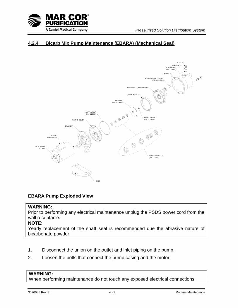
Pressurized Solution Distribution System
3026685 Rev E 4 - 9 Routine Maintenance
4.2.4 Bicarb Mix Pump Maintenance (EBARA) (Mechanical Seal)
GUIDE VANE
IMPELLER
(P/N 1229408)
PLUG
WASHER
PLUG O-RING
(P/N 1229404)
VENTURI TUBE O-RING
(P/N 1229405)
CASING
MECHANICAL SEAL
(P/N 1229407)
REMOVABLE
ACCESS
EBARA Pump Exploded View
WARNING: Prior to performing any electrical maintenance unplug the PSDS power cord from the wall receptacle.
NOTE: Yearly replacement of the shaft seal is recommended due the abrasive nature of bicarbonate powder.
1. Disconnect the union on the outlet and inlet piping on the pump.
2. Loosen the bolts that connect the pump casing and the motor.
WARNING: When performing maintenance do not touch any exposed electrical connections.

Pressurized Solution Distribution System
3026685 Rev E 4 - 10 Routine Maintenance
3. Carefully separate the pump casing from the motor.
4. Remove the 17 mm nut holding the impeller in place. It may be necessary to grip the impeller with large channel lock pliers or a strap wrench. Use extreme caution to avoid damage to the impeller. The impeller is made of stainless steel and will tolerate „gripping‟, but do not „bite‟ into the metal with the pliers. If the impeller is damaged during removal it must be replaced.
5. Remove the access cover from the rear of the motor. Use a large screwdriver to hold the shaft while removing the impeller. Unscrew the impeller from the motor shaft (counter-clockwise).
6. After the impeller is removed, the shaft seal assembly will be exposed. Using two screwdrivers, pry off the rotating part of the shaft seal from the motor shaft and discard. Do not score or scratch shaft.
7. Remove and discard the stationary part of the shaft seal. It can be removed with a small screwdriver.
CAUTION: The new seal may be damaged by the presence of body oil or lubricants on the sealing surfaces. Don‟t touch, mar or scratch the polished surface of either the stationary seal or the rotating seal with spring. It is advisable to handle these parts with rinsed, powder-free latex gloves. Do not allow any lubricants to come in contact with the sealing surfaces.
8. Be sure the stationary seal recess and cover plate are clean. Apply a thin coat of non-toxic silicone lube/soapy water in the surface of the central recess of the cover plate.
9. Gently push the stationary seal assembly into the recess of the cover plate. Be careful not to scratch or mar the face of the seal. Make sure the seal assembly is fully seated into the recess.
10. Clean the motor shaft to remove any debris.
11. Place the rotating assembly of the shaft seal on the motor shaft.
12. Push the assembly along the motor shaft until the 2 shaft seal faces come into contact.
13. Spin the impeller on (clockwise) until the shaft starts to turn. Place the large screwdriver in the motor access and give a quick twist clockwise to finish spinning impeller on. Ensure the impeller is securely on the shaft.
14. Secure the impeller with a strap wrench or large channel lock type pliers and install the 17 mm nut to secure the impeller in place.

Pressurized Solution Distribution System
3026685 Rev E 4 - 11 Routine Maintenance
15. Remove all plugs and jetted ports containing O-rings. Replace with the
appropriate O-ring from the O-ring kit and reinstall into the pump housing plugs, ports and venturi ports.
16. Install the pump casing (large) O-ring onto the casing cover.
17. Replace pump casing cover. Ensure not to pinch or crush O-ring. Reinstall the eight 10 mm hex head bolts. Tighten until snug.
18. Reconnect the unions on the inlet and outlet of the pump.
19. The pump is now ready for testing to ensure there are no leaks and operation is correct.
4.2.5 PSDS Status Monitor Routine Maintenance
The PSDS Status Monitor has been designed to operate with a minimum of operator attention. Operator maintenance on the PSDS Status Monitor is limited to a daily visual and semi-annual operational check. Refer to the troubleshooting section (Chapter 5) in this manual for problems with maintenance operations.
4.2.5.1 Daily PSDS Status Monitor Maintenance
1. Observe the illumination of the Distribution Pump Run and Distribution Tank Low Level Alarm Bypass indicators during normal PSDS unit operation.
2. Observe the illumination of the Alarm indicators during the presence of any associated alarm condition.
4.2.5.2 Semi-Annual PSDS Status Monitor Maintenance
4.2.5.2.1 Distribution Tank Low Level Alarm Verification
1. Ensure the PSDS Main Power and Distribution Tank Low Level Alarm hand switches are in the ON position.
2. Drain the distribution tank to a level below the low-level float switch.
3. Verify the audible alarm sounds and the red Alarm indicator illuminates on the PSDS Status Monitor.
4. Fill the distribution tank to a level above the low-level float switch.
5. Move the Distribution Tank Low Level Alarm hand switch to the RESET/BYPASS position and then back to the ON position.
6. Verify the Distribution Tank Low Level Alarm is discontinued.
7. Turn the PSDS Main Power hand switch to the OFF position.

Pressurized Solution Distribution System
3026685 Rev E 4 - 12 Routine Maintenance
4.2.5.2.2 Distribution Tank High Level Alarm Verification
1. Ensure the PSDS Main Power hand switch is in the ON position and the Distribution Tank Low Level Alarm hand switch is in the RESET/BYPASS position.
2. Prepare the PSDS for solution transfer operation.
3. Turn the PSDS Mix Pump hand switch to the TRANSFER position.
4. Engage the distribution tank high-level float switch. Physically raising the float switch is an acceptable method of engaging the high-level float switch.
5. Verify the audible alarm sounds and the red Alarm indicator illuminates on the PSDS Status Monitor.
6. Turn the PSDS Mix Pump hand switch to the OFF position.
7. Verify the Distribution Tank High Level Alarm is discontinued.
4.2.5.2.3 Mix Pump Low Flow Alarm Verification
1. Ensure the PSDS Main Power hand switch is in the ON position and the Distribution Tank Low Level Alarm hand switch is in the RESET/BYPASS position.
2. Prepare the PSDS for solution mixing operation.
3. Turn the PSDS Mix Pump hand switch to the MIX position.
4. Shut the mix pump outlet valve, V1.
5. Verify the audible alarm sounds and the red Alarm indicator illuminates on the PSDS Status Monitor.
6. Turn the PSDS Mix Pump hand switch to the OFF position and open the mix pump outlet valve, V1.
7. Verify the Distribution Tank High Level Alarm is discontinued.

Pressurized Solution Distribution System
3026685 Rev E 4 - 13 Routine Maintenance
NOTES:

Pressurized Solution Distribution System
3026685 Rev E 4 - 14 Routine Maintenance
This page intentionally left blank.
Pressurized Solution Distribution System
3026685 Rev E 5 - 1 Troubleshooting
Pressurized Solution Distribution System
PSDS
CHAPTER FIVE:
TROUBLESHOOTING

Pressurized Solution Distribution System
3026685 Rev E 5 - 2 Troubleshooting
This page intentionally left blank.

Pressurized Solution Distribution System
3026685 Rev E 5 - 3 Troubleshooting
Troubleshooting Table of Contents
SECTION TITLE PAGE
5.1 Alarms 5-5
5.2 Auto Fill Mode Timer 5-12
5.3 Bicarb Mixing System 5-12
5.4 Distribution Loop Problems (Acid/Bicarb) 5-15
5.5 Leaks 5-15
5.6 Main Power Switch 5-16
5.7 Programmable Logic Controller (PLC) 5-16
5.8 Inlet Solenoid Valve 5-17
5.9 PSDS Status Monitor 5-18

Pressurized Solution Distribution System
3026685 Rev E 5 - 4 Troubleshooting
This page intentionally left blank.

Pressurized Solution Distribution System
3026685 Rev E 5 - 5 Troubleshooting
NOTE: The electrical schematics, flow diagrams, and other drawings included in Chapter 6, will aid in troubleshooting activities.
5.1 Alarms
5.1.1 Low Flow Alarm
1. Operation of the Low Flow Alarm is discussed in Chapter 1, General Information, and should be fully understood to ensure the troubleshooting effort is done with intent to address an unexplained activity of the alarm.
2. Ensure either the mix pump discharge valve (V1); mix tank spray head valve (V2), or distribution tank fill (V7) and distribution inlet valves (V9 and/or V10) is/are open. An open path for solution to pass through the flow switch must be available to measure flow.
3. Ensure there are no loose electrical connections between the associated controller terminal posts (TB-5 & COM), PLC terminal posts (I10 & 24VDC) and mix pump flow switch. Repair any loose electrical connections as necessary.
4. Verify the Low Flow alarm condition is registered on the PLC.
a. The alarm condition will be registered in the PLC with the non-illumination of the associated PLC Input LED #10. If the alarm condition is not being registered in the PLC there may be loose wire connections or failed components including the PLC. Repair any loose electrical connections as necessary and continue to investigate possible component failure if the problem remains unresolved.
5. Verify the Low Flow switch is functional.
a. Ensure the Main Power hand switch is in the OFF position.
b. Disconnect the flow switch from its wiring and verify an infinite resistance across the flow switch leads. If an infinite resistance measurement is not observed the PLC may have failed and require replacement.
c. If a near zero resistance measurement is observed the switch may have been stuck or failed and require replacement.

Pressurized Solution Distribution System
3026685 Rev E 5 - 6 Troubleshooting
5.1.2 Distribution Tank High-Level Alarm
1. Operation of the Distribution Tank High-Level Alarm is discussed in Chapter 1, General Information, and should be fully understood to ensure the troubleshooting effort is done with intent to address an unexplained activity of the alarm.
2. Ensure the distribution tank high-level float switch is installed in the normally closed (NC) position and has not been stuck or broken.
3. Ensure there are no loose electrical connections between the associated controller terminal posts (TB-4 & COM), PLC terminal posts (I9 & 24VDC COM) and distribution tank high-level float switch. Repair any loose electrical connections as necessary.
4. Verify the Distribution Tank High-Level alarm condition is registered on the PLC.
a. The alarm condition will be registered in the PLC with the non-illumination of the associated PLC Input LED #9. If the alarm condition is not being registered in the PLC, there may be loose wire connections or failed components including the PLC. Repair any loose electrical connections as necessary and continue to investigate possible component failure if the problem remains unresolved.
5. Verify the distribution tank high-level float switch is functional.
a. Disconnect the float switch from its wiring and verify continuity across the float switch leads with the switch in the normally closed (NC) position. If continuity is not observed, the switch may have failed and require replacement.
b. Verify an infinite resistance across the float switch leads with the switch in the normally open (NO) position. If a near zero resistance measure is observed, the switch may have failed and require replacement.
c. If correct operation of the float switch is observed, the PLC may have failed and require replacement.
5.1.3 Distribution Tank Low-Level Alarm
1. Operation of the Distribution Tank Low-Level Alarm is discussed in Chapter 1, General Information, and should be fully understood to ensure the troubleshooting effort is done with intent to address an unexplained activity of the alarm.
2. Ensure the distribution tank low-level float switch is installed in the normally open (NO) position and has not been stuck or broken.
3. Ensure there are no loose electrical connections between the associated controller terminal posts (TB-10 & COM), PLC terminal posts (I13 & 24VDC COM), and distribution tank low-level float switch. Repair any loose electrical connections as necessary.
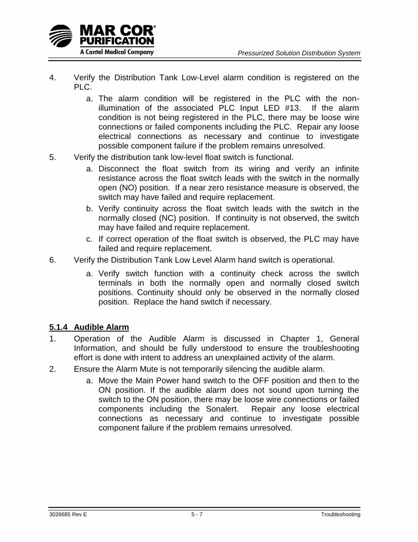
Pressurized Solution Distribution System
3026685 Rev E 5 - 7 Troubleshooting
4. Verify the Distribution Tank Low-Level alarm condition is registered on the PLC.
a. The alarm condition will be registered in the PLC with the non-illumination of the associated PLC Input LED #13. If the alarm condition is not being registered in the PLC, there may be loose wire connections or failed components including the PLC. Repair any loose electrical connections as necessary and continue to investigate possible component failure if the problem remains unresolved.
5. Verify the distribution tank low-level float switch is functional.
a. Disconnect the float switch from its wiring and verify an infinite resistance across the float switch leads with the switch in the normally open (NO) position. If a near zero resistance measure is observed, the switch may have failed and require replacement.
b. Verify continuity across the float switch leads with the switch in the normally closed (NC) position. If continuity is not observed, the switch may have failed and require replacement.
c. If correct operation of the float switch is observed, the PLC may have failed and require replacement.
6. Verify the Distribution Tank Low Level Alarm hand switch is operational.
a. Verify switch function with a continuity check across the switch terminals in both the normally open and normally closed switch positions. Continuity should only be observed in the normally closed position. Replace the hand switch if necessary.
5.1.4 Audible Alarm
1. Operation of the Audible Alarm is discussed in Chapter 1, General Information, and should be fully understood to ensure the troubleshooting effort is done with intent to address an unexplained activity of the alarm.
2. Ensure the Alarm Mute is not temporarily silencing the audible alarm.
a. Move the Main Power hand switch to the OFF position and then to the ON position. If the audible alarm does not sound upon turning the switch to the ON position, there may be loose wire connections or failed components including the Sonalert. Repair any loose electrical connections as necessary and continue to investigate possible component failure if the problem remains unresolved.

Pressurized Solution Distribution System
3026685 Rev E 5 - 8 Troubleshooting
3. Verify the known alarm condition is registered on the PLC.
a. The alarm condition will be registered in the PLC with the non-illumination of the associated PLC Input LED# (9, 10, or 13). If the alarm condition is not being registered in the PLC, there may be loose wire connections or failed components including the PLC.
b. Ensure there are no loose electrical connections between the associated controller terminal posts, PLC terminal posts, and Sonalert. Repair any loose electrical connections as necessary and continue to investigate possible component failure if the problem remains unresolved.
4. Verify power is being supplied to the Sonalert.
a. The Sonalert‟s PLC Output LED # 8 should be lit in the presence of the known alarm condition. If the Output LED #8 is off, the PLC may be defective and need replacement.
5. Verify the Sonalert is functioning.
a. Verify continuity between PSDS controller terminal post 24N and the negative terminal (-) on the Sonalert. Repair and/or reconnect any loose wires as necessary.
b. Verify continuity between PLC Output LED #8, PSDS controller terminal post 16, and the positive terminal (+) on the Sonalert. Repair and/or reconnect any loose wires as necessary.
c. If the Sonalert‟s PLC Output LED #8 is lit and continuity has been verified, the Sonalert may be defective and need replacement.
5.1.5 Distribution Pump Run Light
1. Ensure the distribution pump fuse (5 Amp) is not blown and there are no loose electrical connections between the associated controller terminal posts, control relay (CR1), hand switch (HS-3), and light (LT1). Replace the fuse and/or repair any loose electrical connections as necessary.
2. Verify the Distribution Pump Run light is receiving power.
a. Place the Main Power and Distribution Pump hand switches in the ON position.
b. Verify an 115VAC measurement (approximate) across the light (LT1) terminals. If the voltage is verified and the light is not lit, it may have failed and require replacement. If the voltage is not verified there may be loose wire connections or failed components. Repair any loose electrical connections as necessary and continue to investigate possible component failure if the problem remains unresolved.
3. Verify the distribution pump control relay (CR1) is functional.
a. Place the Main Power switch in the ON position.

Pressurized Solution Distribution System
3026685 Rev E 5 - 9 Troubleshooting
b. Toggle the Distribution Pump hand switch several times while
observing the control relay (CR1) for movement of the relay contact arm. With the distribution pump hand switch in the ON position, verify voltage across the control relay (CR1) terminals 13 and 14. If the relay arm is not moving with switch activation and/or voltage is confirmed across terminals 13 and 14, the relay may have failed and require replacement.
4. Verify the Distribution Pump hand switch is operational.
a. Verify switch function with a continuity check across the switch terminals in both the normally open and normally closed switch positions. Continuity should only be observed in the normally closed position. Replace the hand switch if necessary.
5.1.6 Distribution Tank Low Level Light
1. Ensure there are no loose electrical connections between the associated controller terminal posts, hand switch (HS-5), PLC, and light (LT2). Repair any loose electrical connections as necessary.
2. Verify the Distribution Tank Low Level light is receiving power.
a. Place the Main Power and Distribution Tank Low Level hand switches in the ON position.
b. Create a distribution tank low-level alarm condition or disconnect the low-level float switch wires at the tank and connect the two ends to provide a circuit jumper.
c. Verify a 24VAC measurement (approximate) across the light (LT2) terminals. If the voltage is verified and the light is not lit, it may have failed and require replacement. If the voltage is not verified there may be loose wire connections or failed components. Repair any loose electrical connections as necessary and continue to investigate possible component failure if the problem remains unresolved.
d. If applicable, reconnect the Distribution Tank low-level float switch wires once verification operations have been completed.
3. Verify the Distribution Tank Low Level hand switch is operational.
a. Verify switch function with a continuity check across the switch terminals in both the normally open and normally closed switch positions. Continuity should only be observed in the normally closed position. Replace the hand switch if necessary.
4. Verify the distribution tank low-level alarm is functional. Reference the Distribution Tank Low Level Alarm section of this chapter for additional troubleshooting instruction.

Pressurized Solution Distribution System
3026685 Rev E 5 - 10 Troubleshooting
5.1.7 Acid Tank Pump Run Light(s)
1. Ensure the acid pump fuse (2.5 Amp) in the Acid Pump Controller is not blown and there are no loose electrical connections between the associated controller terminal posts, control relay (CR5, CR6, or CR7), hand switch (HS-6, HS-7, or HS-8), and light (LT3, LT5, or LT7). Replace the fuse and/or repair any loose electrical connections as necessary.
2. Verify the Acid Tank Pump Run light is receiving power.
a. Place the Main Power and Acid Tank hand switch (HS-6, HS-7, or HS-8) in the ON position.
b. Verify a 24VAC measurement (approximate) across the light (LT3, LT5, or LT7) terminals. If the voltage is verified and the light is not lit it may have failed and require replacement. If the voltage is not verified, there may be loose wire connections or failed components. Repair any loose electrical connections as necessary and continue to investigate possible component failure if the problem remains unresolved.
3. Verify the acid pump control relay (CR5, CR6, or CR7) is functional.
a. Place the Main Power switch and the Acid Tank hand switch (HS-6, HS-7, or HS-8) in the ON position while observing the associated control relay for movement of the relay contact arm. Verify voltage across the control relay (CR5, CR6, or CR7) terminals 13 and 14. If the relay arm is not moving with switch activation and/or voltage is confirmed across terminals 13 and 14, the relay may have failed and require replacement.
4. Verify the Acid Tank hand switch is operational.
a. Verify switch function with a continuity check across the switch terminals in both the normally open and normally closed switch positions. Continuity should only be observed in the normally closed position. Replace the hand switch if necessary.

Pressurized Solution Distribution System
3026685 Rev E 5 - 11 Troubleshooting
5.1.8 Acid Tank Low Level Light(s)
1. Ensure the associated acid tank low-level float switch is installed in the normally closed (NC) position and has not been stuck or broken.
2. Ensure there are no loose electrical connections between the associated controller terminal posts, control relay (CR2, CR3, or CR4), and light (LT4, LT6, or LT8). Repair any loose electrical connections as necessary.
3. Verify the Acid Tank Low Level light is receiving power.
a. Place the Main Power hand switch in the ON position.
b. Verify a 24VAC measurement (approximate) across the light (LT4, LT6, or LT8) terminals. If the voltage is verified and the light is not lit, it may have failed and require replacement. If the voltage is not verified there may be loose wire connections or failed components. Repair any loose electrical connections as necessary and continue to investigate possible component failure if the problem remains unresolved.
4. Verify the acid tank low-level float switch is functional.
a. Disconnect the float switch from its wiring and verify an infinite resistance across the float switch leads with the switch in the normally open (NO) position. If a near zero resistance measure is observed, the switch may have failed and require replacement.
b. Verify continuity across the float switch leads with the switch in the normally closed (NC) position. If continuity is not observed, the switch may have failed and require replacement.
c. If correct operation of the float switch is observed, there may be loose wire connections or failed components. Repair any loose electrical connections as necessary and continue to investigate possible component failure if the problem remains unresolved.
5. Verify the acid tank low-level control relay (CR2, CR3, or CR4) is functional.
a. Disconnect the Acid Tank float switch wires at the tank and connect the two ends to provide a circuit jumper.
b. Place the Main Power switch in the ON position while observing the associated control relay for movement of the relay contact arm. Verify voltage across the control relay (CR2, CR3, or CR4) terminals 13 and 14. If the relay arm is not moving with switch activation and/or voltage is confirmed across terminals 13 and 14, the relay may have failed and require replacement.
c. If applicable, reconnect the Acid Tank float switch wires once verification operations have been completed.

Pressurized Solution Distribution System
3026685 Rev E 5 - 12 Troubleshooting
5.2 Auto-Fill Mode Timer
5.2.1 Auto Fill Mode Timer Display Window (LCD) Is Blank
1. Operation of the Auto-Fill Mode Timer is discussed in Chapter 1, General Information, and should be fully understood to ensure the troubleshooting effort is done with intent to address an unexplained activity of the alarm.
2. Ensure there are no loose electrical connections between the associated controller terminal posts (6, 13, 24N, & COM), PLC terminal posts (I8, Q6, Q7, Input & Output Common), and the timer relay base (Posts 2, 3, 6, 7, 9, 10, & 11). Repair any loose electrical connections as necessary.
3. Ensure the power cord is connected to an 115VAC power and the main power switch is turned to the ON position.
4. Verify the Auto Fill Timer is receiving power.
a. Place the Main Power hand switch in the ON position.
b. Verify a 24VAC measurement (approximate) across terminals #2 and #10 of the timer relay base. If the voltage is verified, the Auto Fill Timer may be defective and require replacement. If the voltage is not verified, there may be loose wire connections or failed components. Repair any loose electrical connections as necessary and continue to investigate possible component failure if the problem remains unresolved.
5.2.2 No Water Flow (With Timer Operating Correctly)
1. Ensure the water supply valve, flow meter needle valve (V8), and inlet water valves (V3 and V1 or V2) are open.
2. If the valve positioning is correctly verified, the Inlet Solenoid may be defective and require replacement. Reference the Inlet Solenoid troubleshooting section in this chapter for additional verification operations.
5.3 Bicarb Mixing System
5.3.1 Mix Pump Motor Does Not Start
1. Ensure the circuit breaker, located on the left side panel of the controller, is in the ON position.
2. Ensure there are no loose electrical connections between the associated controller terminal posts (H, 1, 2, N, & 24N), PLC terminal posts (Q12 & 24VAC COM), motor contactor relay (MCR1), circuit breaker (CB-1), and motor contactor (C-1). Repair any loose electrical connections as necessary.
3. Ensure the power cord is connected to 115VAC power and the main power switch is in the ON position.

Pressurized Solution Distribution System
3026685 Rev E 5 - 13 Troubleshooting
4. If the Mix Pump hand switch is in the Mix position and the motor will not start, ensure the low flow alarm is not being activated.
a. Verify the Low Flow alarm is functional. Reference the Low Flow Alarm section of this chapter for additional troubleshooting instruction.
5. If the Mix Pump hand switch is in the Transfer position and the motor will not start, ensure that both the low flow alarm and distribution tank high-level switch alarm are not being activated.
a. Verify the Low Flow and Distribution Tank High-Level alarms are functional. Reference the Low Flow Alarm and Distribution Tank High-Level Alarm sections of this chapter for additional troubleshooting instruction.
6. Verify the mix pump signal is registered on the PLC.
a. The mix pump signal will be registered in the PLC with the illumination of PLC Input LED #2 (Mix Pump „ON‟ Signal) or PLC Output LED #12 (Mix Pump „RUN‟ Signal). If the mix pump signal is not being registered in the PLC, there may be loose wire connections or failed components including the PLC. Repair any loose electrical connections as necessary and continue to investigate possible component failure if the problem remains unresolved.
7. Verify the Mix Pump hand switch is operational.
a. Verify switch function with a continuity check across the switch terminals in both the normally open and normally closed switch positions. Continuity should only be observed in the normally closed position. Replace the hand switch if necessary.
8. Verify the motor contactor relay (MCR1) is functional.
a. Verify an 115VAC voltage (approximate) measurement across the motor contactor relay terminals „4‟ and „7‟. If the voltage is not verified, the motor contactor relay may have failed and require replacement.
b. Verify a 24VAC voltage (approximate) measurement across the motor contactor relay terminals „6‟ and „9‟. If the voltage is not verified, the motor contactor relay may have failed and require replacement.
9. Verify the motor contactor (C-1) is functional.
WARNING: The motor contactor contains exposed metal parts, which normally carry high voltage electrical power (115 VAC). Do not touch the contactor except as required using appropriate insulated test meter leads.

Pressurized Solution Distribution System
3026685 Rev E 5 - 14 Troubleshooting
a. Toggle the Mix Pump switch a few times while looking for movement of the C-1 relay arm. If no movement is observed, the motor contactor may have failed and require replacement.
b. Verify a 24VAC voltage (approximate) measurement across the PLC terminal „Q12‟ and controller terminal „24N‟. If the voltage is not confirmed, the contactor may have failed and require replacement.
c. Verify an 115VAC voltage (approximate) measurement across controller terminal „2‟ and motor contactor terminal „5‟ while the Mix Pump hand switch is in either the Mix or Transfer positions. If no voltage is confirmed at C1-5, make sure the circuit breaker is in the ON position. If the circuit breaker is in the ON position and no voltage is confirmed at controller terminal „2‟, the motor contactor may have failed and require replacement.
10. Verify an 115VAC voltage (approximate) measurement across the controller terminal blocks „2‟ and „N‟ and at the comparable motor connections. Repair any loose connections as necessary.
a. If the voltage is confirmed at the motor and it does not run, it may have failed and require replacement.
5.3.2 Mix Pump Leaks
1. If the mix pump is leaking at the inlet or outlet piping, disconnect the plumbing at the unions and replace the Teflon tape on the pipe threads. Reconnect fittings and check for leaks during operation. Reference the Leak Repair sections in Chapter 4 for additional repair instruction.
2. If the pump housing (stainless steel cover) is leaking, attempt to stop the leak by tightening the pump casing bolts. Additional replacement of the pump casing O-ring may be required to stop this leak.
NOTE: A leak in the pump housing seal is usually seen as a small puddle of fluid directly below the motor. Bicarbonate solution is corrosive to some metals, and if left unattended, will cause damage to the pump backing plate (or „motor stool‟). Quick action to repair the leak can help reduce maintenance and repair expense.
3. If the pump shaft seal (mechanical seal) is leaking, the shaft seal must be
replaced. Reference the Mix Pump Maintenance section in Chapter 4 for instruction.
CAUTION: A leak in this area can cause damage to the motor, and/or motor stool, so it is best to repair it immediately.
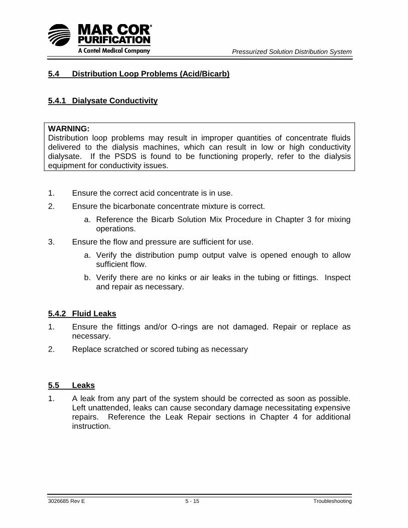
Pressurized Solution Distribution System
3026685 Rev E 5 - 15 Troubleshooting
5.4 Distribution Loop Problems (Acid/Bicarb)
5.4.1 Dialysate Conductivity
WARNING: Distribution loop problems may result in improper quantities of concentrate fluids delivered to the dialysis machines, which can result in low or high conductivity dialysate. If the PSDS is found to be functioning properly, refer to the dialysis equipment for conductivity issues.
1. Ensure the correct acid concentrate is in use.
2. Ensure the bicarbonate concentrate mixture is correct.
a. Reference the Bicarb Solution Mix Procedure in Chapter 3 for mixing operations.
3. Ensure the flow and pressure are sufficient for use.
a. Verify the distribution pump output valve is opened enough to allow sufficient flow.
b. Verify there are no kinks or air leaks in the tubing or fittings. Inspect and repair as necessary.
5.4.2 Fluid Leaks
1. Ensure the fittings and/or O-rings are not damaged. Repair or replace as necessary.
2. Replace scratched or scored tubing as necessary
5.5 Leaks
1. A leak from any part of the system should be corrected as soon as possible. Left unattended, leaks can cause secondary damage necessitating expensive repairs. Reference the Leak Repair sections in Chapter 4 for additional instruction.

Pressurized Solution Distribution System
3026685 Rev E 5 - 16 Troubleshooting
5.6 Main Power Switch
5.6.1 No Power
1. Ensure the power cord is connected to an 115VAC power supply.
2. Ensure the circuit breaker, located on the left side panel of the controller, is in the ON position.
3. Ensure the primary fuse (1 Amp) and secondary fuse (1.5 Amp) are not blown and there are no loose electrical connections between the associated controller terminal posts, circuit breaker (CB-1), motor contactor (C-1), motor contactor relay (MCR1), and hand switch (HS-1). Replace the fuse and/or repair any loose electrical connections as necessary.
4. Verify the Main Power hand switch is operational.
a. Verify switch function with a continuity check across the switch terminals in both the normally open and normally closed switch positions. Continuity should only be observed in the normally closed position. Replace the hand switch if necessary.
5. Verify the transformer is functional. a. Verify the 115VAC primary voltage (approximate) measurement across
the transformer end of the primary fuse (1 Amp) and controller terminal „N‟.
b. Verify the 24VAC secondary voltage (approximate) measurement across the transformer end of the secondary fuse (1.5 Amp) and controller terminal „24N‟.
c. If the primary voltage is verified and the secondary voltage is not, the transformer may have failed and require replacement.
5.7 Programmable Logic Controller (PLC)
1. Ensure the main power switch is in the ON position and all three PLC „PWR‟, „OK‟ and „RUN‟ LED‟s are illuminated. If these LED‟s are not illuminated the PLC may have failed and require replacement.
a. Ensure the Run/Program switch on the PLC is in the Run mode. If the PLC „PWR‟ and „OK‟ LED‟s are both lit with the „RUN‟ LED off, the PLC may have failed and require replacement.
b. If the PLC „PWR” LED is lit with the „OK‟ and „RUN‟ LED‟s off, the PLC may have failed and require replacement.
NOTE: Other LED‟s may also be lit depending upon the status of the hand switches and float switches.
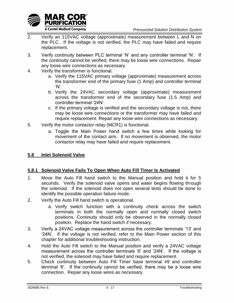
Pressurized Solution Distribution System
3026685 Rev E 5 - 17 Troubleshooting
2. Verify an 115VAC voltage (approximate) measurement between L and N on the PLC. If the voltage is not verified, the PLC may have failed and require replacement.
3. Verify continuity between PLC terminal „N‟ and any controller terminal „N‟. If the continuity cannot be verified, there may be loose wire connections. Repair any loose wire connections as necessary.
4. Verify the transformer is functional. a. Verify the 115VAC primary voltage (approximate) measurement across
the transformer end of the primary fuse (1 Amp) and controller terminal „N‟.
b. Verify the 24VAC secondary voltage (approximate) measurement across the transformer end of the secondary fuse (1.5 Amp) and controller terminal „24N‟.
c. If the primary voltage is verified and the secondary voltage is not, there may be loose wire connections or the transformer may have failed and require replacement. Repair any loose wire connections as necessary.
5. Verify the motor contactor relay (MCR1) is functional.
a. Toggle the Main Power hand switch a few times while looking for movement of the contact arm. If no movement is observed, the motor contactor relay may have failed and require replacement.
5.8 Inlet Solenoid Valve
5.8.1 Solenoid Valve Fails To Open When Auto Fill Timer Is Activated
1. Move the Auto Fill hand switch to the Manual position and hold it for 5 seconds. Verify the solenoid valve opens and water begins flowing through the solenoid. If the solenoid does not open several tests should be done to identify the possible operation failure mode.
2. Verify the Auto Fill hand switch is operational.
a. Verify switch function with a continuity check across the switch terminals in both the normally open and normally closed switch positions. Continuity should only be observed in the normally closed position. Replace the hand switch if necessary.
3. Verify a 24VAC voltage measurement across the controller terminals „13‟ and „24N‟. If the voltage is not verified, refer to the Main Power section of this chapter for additional troubleshooting instruction.
4. Hold the Auto Fill switch to the Manual position and verify a 24VAC voltage measurement across the controller terminals „6‟ and „24N‟. If the voltage is not verified, the solenoid may have failed and require replacement.
5. Check continuity between Auto Fill Timer base terminal #9 and controller terminal „6‟. If the continuity cannot be verified, there may be a loose wire connection. Repair any loose wires as necessary.

Pressurized Solution Distribution System
3026685 Rev E 5 - 18 Troubleshooting
6. Hold the Auto Fill hand switch to the MANUAL position and verify continuity between the PLC 24VDC COM and PLC Input LED #8. If the continuity cannot be verified, the PLC may have failed and require replacement.
7. Turn the Auto Fill hand switch to the MANUAL position several times and verify PLC Input LED #8 lights each time the switch is turned to the Start position. If the LED illumination cannot be verified, the electrical connections may be loose and need to be repaired.
8. Turn the Auto Fill hand switch to the START position several times and verify PLC Output LED #6 or #7 light momentarily each time Input LED #8 lights. If the LED illumination cannot be verified, the PLC may have failed and require replacement.
9. Turn the Auto Fill hand switch to the START position several times and verify the Auto-Fill Timer window displays the flashing word „ON‟ when PLC Output LED #6 lights. Verify the Auto-Fill Timer window displays the word „OFF‟ when PLC Output LED #7 lights. If the combination of the lights and window display cannot be verified, there may be loose wire connections, the Auto Fill Timer settings may be incorrect, or the Auto Fill Timer may have failed and require replacement. Repair any loose wire connections and/or reset the Auto Fill Timer as required. Reference the Auto Fill Timer procedure.
5.8.2 Solenoid Valve Fails To Close 1. If the solenoid valve fails to close upon completion of the filling operations, it
may be stuck open. Turn the Auto Fill hand switch to the Manual position several times to clear an obstruction or free a sticky valve. Replace the solenoid valve if it‟s failure to close upon completion of the filling operations is repeated.
5.9 PSDS Status Monitor
Reference the PSDS wiring diagram in Chapter 6 for a visual description of wire connection locations.
5.9.1 Failed Indicator Lights
1. Connections
a. Verify the indicator wire leads inside the PSDS Status Monitor are correctly and securely attached to the cable connection.
b. Verify the wire lead connections inside the PSDS controller are correctly and securely attached.
c. Restore connections as required.
2. Indicators
a. Verify the indicator lamps have not burnt out with a continuity check across the terminal connections.
b. Replace indicator as necessary.

Pressurized Solution Distribution System
3026685 Rev E 5 - 19 Troubleshooting
5.9.2 Failed Audible Alarm
1. Connections
a. Verify the Sonalert‟s wire leads inside the PSDS Status Monitor are correctly and securely attached to the cable connection.
b. Verify the Sonalert‟s wire lead connections inside the PSDS controller are correctly and securely attached.
c. Restore connections as required.
2. Sonalert
a. Verify the Sonalert is operative with the application of a 24 VAC power source across the terminal connections.
b. Replace Sonalert as necessary.
5.9.3 Failed Mute Switch
1. Connections
a. Verify the mute switch wire leads inside the PSDS Status Monitor are correctly and securely attached to the cable connection.
b. Verify the mute switch wire lead connections inside the PSDS controller are correctly and securely attached.
c. Restore connections as required.
2. Mute Switch
a. Verify the „momentary on‟ mute switch is operative with a continuity check while pressing the mute switch.
b. Replace switch as necessary.

Pressurized Solution Distribution System
3026685 Rev E 5 - 20 Troubleshooting
NOTES:

Pressurized Solution Distribution System
3026685 Rev E 6 - 1 Drawings
Pressurized Solution Distribution System
PSDS
CHAPTER SIX:
DRAWINGS

Pressurized Solution Distribution System
3026685 Rev E 6 - 2 Drawings
This page intentionally left blank.

Pressurized Solution Distribution System
3026685 Rev E 6 - 3 Drawings
Illustration Notes:
1. This manual includes drawings that cover available components and configurations. Some drawings may not be applicable to your unit.
2. The PSDS controller electrical schematic and system wiring diagram are included at the end of this manual in a larger fold out format to aid readability. The PSDS controller electrical schematic includes notes specifying the differences of the multiple acid configurations. The PSDS wiring diagram includes connections for the multiple acid configurations.
List of Illustrations:
6-1 PSDS Assembly
6-2 PSDS Valve Numbers and Locations
6-3 PSDS Bicarb Loop Flow Schematic
6-4 PSDS Acid Loop Flow Schematic
6-5 PSDS Controller Display Panel – Front View
6-6 PSDS Controller Display Panel – Rear View
6-7 PSDS Controller Components – Inside
6-8 GE VersaMax PLC
6-9 Electrical Component – Control Relay Base and Motor Contact
6-10 Electrical Component – Auto Fill Timer
6-11 Mix Pump/Motor Detail
6-12 Mix Pump Electrical Configuration
6-13 PSDS Mix Tank
6-14 PSDS Distribution Tank
6-15 PSDS Mix Tank to Frame Assembly
6-16 PSDS Distribution Tank to Frame Assembly
6-17 PSDS Drain Assembly
6-18 PSDS Bicarb Loop Connections
6-19 PSDS Acid Distribution Loop Connections
6-20 PSDS Acid Tank Connections
6-21 PSDS Status Monitor, Surface Mount Model
6-22 PSDS Status Monitor, Flush Mount Model
6-23 PSDS Wiring Diagrams (Located at the end of manual)

Pressurized Solution Distribution System
3026685 Rev E 6 - 4 Drawings
Illustration 6-1: PSDS Assembly
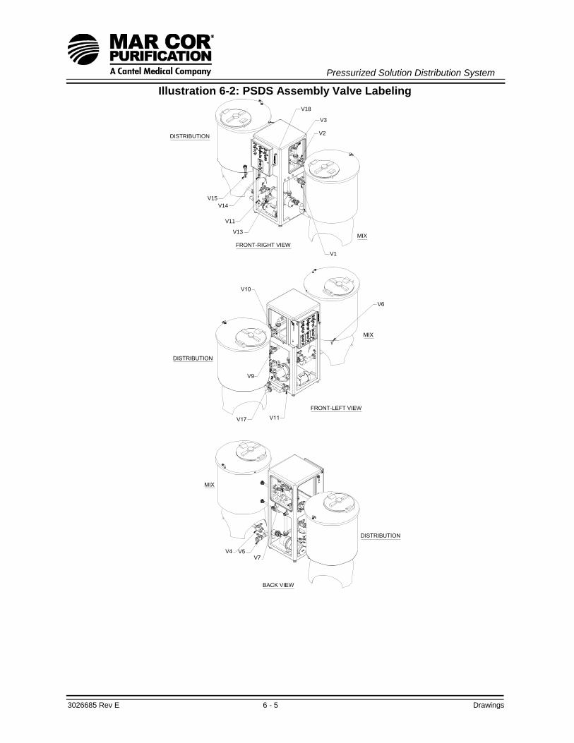
Pressurized Solution Distribution System
3026685 Rev E 6 - 5 Drawings
Illustration 6-2: PSDS Assembly Valve Labeling
FRONT-RIGHT VIEW
DISTRIBUTION
MIX
V15
V14
V11
V3
V2
V1
V13
V18

Pressurized Solution Distribution System
3026685 Rev E 6 - 6 Drawings
Illustration 6 - 3: PSDS Bicarb Loop Flow Schematic
WA
TE
RR
O S
UP
PL
Y
DR
AIN
LO
OP
RE
TU
RN
BIC
AR
B
TO
LO
OP
BIC
AR
B
V8
V3
V1
V4
V5
V10
V9
V15
V11
V14
V13
2
1
11
12
54 18
6 10
16
14
16
19
14
20
24
25
3
15
17
9
13
15
21
22
24
27
28
30
78
31
V2
V6
V7
32
DR
AIN
DR
AIN
V18
26
V17
MIX
TA
NK
DIS
TR
IBU
TIO
N T
AN
K
INL
ET
SO
LE
NO
ID1
DE
SC
RIP
TIO
NIT
EM
AD
JU
ST
AB
LE
IN
LE
T F
LO
W M
ET
ER
(V
8)
2
CH
EC
K V
AL
VE
3
INL
ET
WA
TE
R V
AL
VE
(V
3)
4
MIX
TA
NK
SP
RA
Y H
EA
D S
UP
PL
Y V
AL
VE
(V
2)
5
MIX
PU
MP
DIS
CH
AR
GE
VA
LV
E (
V1
)6
MIX
ED
UC
TO
R7
MIX
TA
NK
DR
AIN
8
MIX
PU
MP
SU
CT
ION
VA
LV
E (
V4
)9
MIX
TA
NK
DR
AIN
VA
LV
E (
V5
)1
0
MIX
PU
MP
11
FL
OW
SW
ITC
H1
2
DIS
TR
IBU
TIO
N T
AN
K F
ILL
VA
LV
E (
V7
)1
3
TA
NK
LID
AN
D S
EA
L1
4
VE
NT
FIL
TE
R1
5
SP
RA
Y H
EA
D1
6
MIX
TA
NK
17
DIS
TR
IBU
TIO
N F
ILL
CH
EC
K V
AL
VE
18
DIS
TR
IBU
TIO
N T
AN
K S
PR
AY
HE
AD
SU
PP
LY
VA
LV
E (
V1
0)
19
DIS
TR
IBU
TIO
N I
NL
ET
VA
LV
E (
V9
)2
0
DIS
TR
IBU
TIO
N T
AN
K H
IGH
-LE
VE
L S
WIT
CH
(N
O)
21
DIS
TR
IBU
TIO
N T
AN
K L
OW
-LE
VE
L S
WIT
CH
(N
O)
22
DIS
TR
IBU
TIO
N T
AN
K D
RA
IN V
AL
VE
(V
18
)
23
DIS
TR
IBU
TIO
N T
AN
K D
RA
IN
24
BIC
AR
BO
NA
TE
SU
PP
LY
VA
LV
E (
V1
5)
25
DIS
TR
IBU
TIO
N P
UM
P S
UC
TIO
N V
AL
VE
(V
11
)
26
27
DIS
TR
IBU
TIO
N P
UM
P
28
DIS
TR
IBU
TIO
N F
LO
W C
ON
TR
OL
VA
LV
E (
V1
3)
30
DIS
TR
IBU
TIO
N R
ET
UR
N V
AL
VE
(V
14
) 3
WA
Y
31
DIS
TR
IBU
TIO
N T
AN
K
32
MIX
TA
NK
SA
MP
LE
VA
LV
E (
V6
)
33
SU
PP
LY
WA
TE
R S
HU
T-O
FF
VA
LV
E
DE
SC
RIP
TIO
NIT
EM
34
WA
TE
RR
O R
ET
UR
N3
3
34
DIS
TR
IBU
TIO
N L
OO
P S
AM
PL
E V
AL
VE
(V
17)

Pressurized Solution Distribution System
3026685 Rev E 6 - 7 Drawings
Illustration 6-4: PSDS Acid Loop Flow Schematic
AC
IDL
OO
P R
ET
UR
N
AC
IDT
O L
OO
P
V4
V1
V2
DR
AIN
8
3
4
5
1
2
7
ITE
MD
ES
CR
IPT
ION
BU
LK
AC
ID T
AN
K1
AC
ID T
AN
K L
OW
-LE
VE
L S
WIT
CH
(N
C)
2
AC
ID D
ELIV
ER
Y P
UM
P IN
LE
T V
ALV
E (
V1)
3
AC
ID T
AN
K D
RA
IN V
AL
VE
(V
2)
4
AC
ID D
ELIV
ER
Y P
UM
P5
DIS
TR
IBU
TIO
N L
OO
P P
RE
SS
UR
E7
AC
ID L
OO
P R
ET
UR
N V
ALV
E (
V4)
8
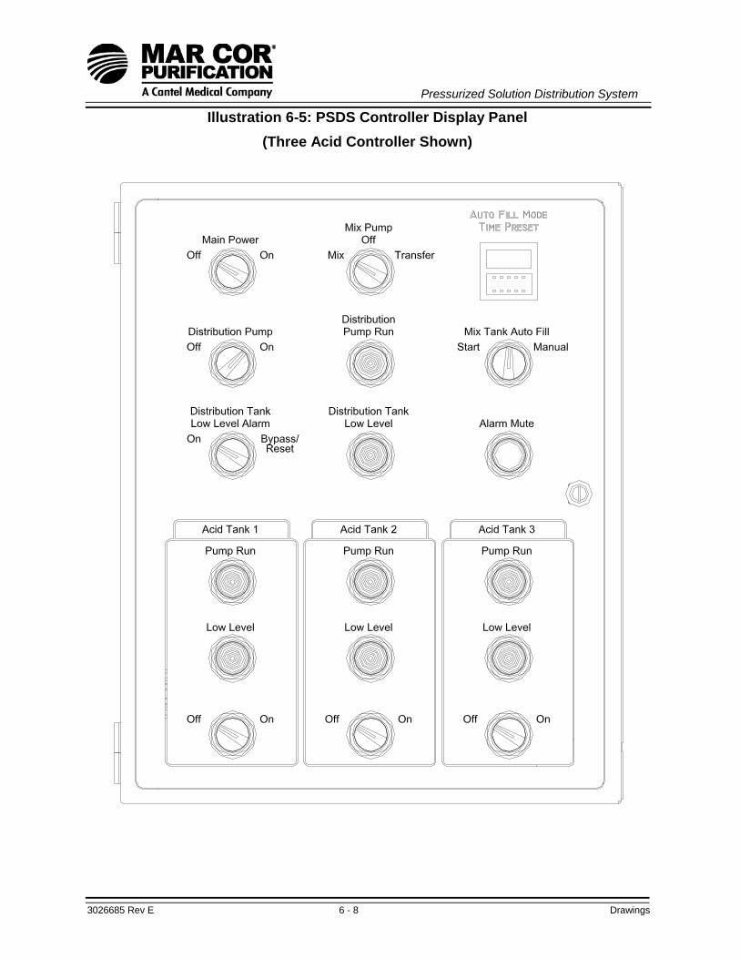
Pressurized Solution Distribution System
3026685 Rev E 6 - 8 Drawings
Illustration 6-5: PSDS Controller Display Panel
(Three Acid Controller Shown)

Pressurized Solution Distribution System
3026685 Rev E 6 - 9 Drawings
Illustration 6-6: PSDS Controller Display Panel (Rear View)
(Three Acid Controller Shown)
(LT-8)
(LT-7)
(LT-4)
(LT-3)
(LT-6)
(LT-5)
(PB-1)
(HS-4)
2
3
4
5
(T-1)
10
9
8
1
6
11
7
(LT-1)
(HS-5)
(HS-1)

Pressurized Solution Distribution System
3026685 Rev E 6 - 10 Drawings
Illustration 6-7: PSDS Controller Components
(Three Acid Controller Shown)

Pressurized Solution Distribution System
3026685 Rev E 6 - 11 Drawings
Illustration 6-8: Mar Cor VersaMax PLC
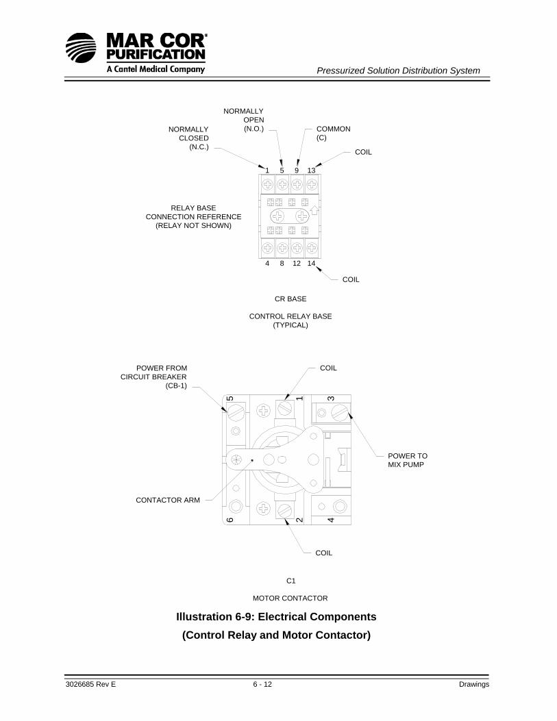
Pressurized Solution Distribution System
3026685 Rev E 6 - 12 Drawings
5
8
NORMALLY
OPEN
(N.O.)
CR BASE
CONTROL RELAY BASE
(TYPICAL)
C1
MOTOR CONTACTOR
POWER FROM
CIRCUIT BREAKER
(CB-1)
CONTACTOR ARM
65
NORMALLY
CLOSED
(N.C.)
RELAY BASE
CONNECTION REFERENCE
(RELAY NOT SHOWN)
4
1
COIL
POWER TO
MIX PUMP
2 4
1
COIL
3
COMMON
(C)
COIL
COIL
12 14
9 13
Illustration 6-9: Electrical Components
(Control Relay and Motor Contactor)

Pressurized Solution Distribution System
3026685 Rev E 6 - 13 Drawings
Illustration 6-10: Electrical Component (Auto Fill Timer)

Pressurized Solution Distribution System
3026685 Rev E 6 - 14 Drawings
GU
IDE
VA
NE
IMP
ELLE
R
(P/N
1229408)
PLU
G
WA
SH
ER
PLU
G O
-RIN
G
(P/N
1229404)
VE
NT
UR
I T
UB
E O
-RIN
G
(P/N
1229405)
CA
SIN
G
ME
CH
AN
ICA
L S
EA
L
(P/N
1229407)
RE
MO
VA
BLE
AC
CE
SS
Illustration 6-11: Mix Pump/Motor Detail

Pressurized Solution Distribution System
3026685 Rev E 6 - 15 Drawings
1
5
115 VAC WIRING
6) REPLACE COVER. REMOVE 230 VOLT STICKER FROM HOUSING. THIS WIRING IS FOR 115 VOLTS.
WARNING: ROUTE WIRES AWAY FROM ROTATING CENTRIFUGAL SWITCH. WHITE WIRE TO TERMINAL 6, AND CONNECT THE GREEN WIRE TO THE GROUND SCREW. 5) CONNECT THE BLACK WIRE FROM 18-3 CORD (P/N ME60011) TO TERMINAL 1. CONNECT THE 4) RECONNECT BROWN WIRE TO TERMINAL MARKED 5. 3) RECONNECT WHITE WIRE TO TERMINAL MARKED 6.
2) REMOVE COVER. DISCONNECT BROWN WIRE FROM TERMINAL MARKED 3 AND WHITE WIRE
1) MOTOR CAN BE WIRED FOR 230 VOLT OR 120 VOLT OPERATION. THE SDS ELECTRICAL
THE FOLLOWING ARE THE STEPS REQUIRED TO RECONFIGURE A REPLACEMENT MOTOR FROM 230 TO 115
REQUIRES 115 VOLT CONFIGURATION.
VOLT OPERATION:
WARNING: DISCONNECT ELECTRICAL POWER PRIOR TO SERVICING.
43
2
6
GREEN WIRE (USE TERMINAL
RING P/N ME60311)
BLACK WIRE (USE QD
TERMINAL P/N ME60486)
WHITE WIRE (USE QD
TERMINAL P/N ME60486)
FROM TERMINAL MARKED 5.
Illustration 6-12: Mix Pump Electrical Configuration
(Rear of Motor Shown Without Cover)
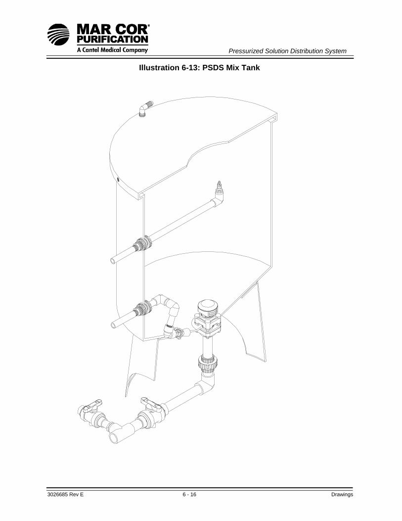
Pressurized Solution Distribution System
3026685 Rev E 6 - 16 Drawings
Illustration 6-13: PSDS Mix Tank
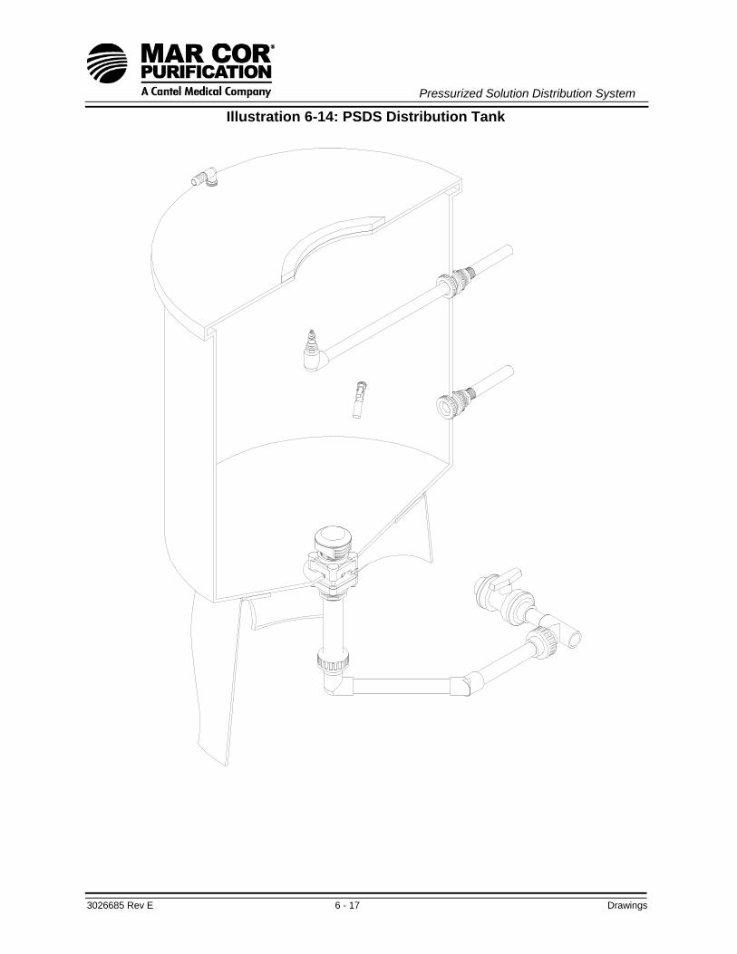
Pressurized Solution Distribution System
3026685 Rev E 6 - 17 Drawings
Illustration 6-14: PSDS Distribution Tank

Pressurized Solution Distribution System
3026685 Rev E 6 - 18 Drawings
Illustration 6-15: PSDS Mix Tank To Frame Assembly

Pressurized Solution Distribution System
3026685 Rev E 6 - 19 Drawings
Illustration 6-16: PSDS Distribution Tank To Frame Assembly

Pressurized Solution Distribution System
3026685 Rev E 6 - 20 Drawings
Illustration 6- 17: PSDS Drain Installation

Pressurized Solution Distribution System
3026685 Rev E 6 - 21 Drawings
Illustration 6-18: Bicarb Distribution Loop Connections

Pressurized Solution Distribution System
3026685 Rev E 6 - 22 Drawings
Illustration 6-19: Bicarb Distribution Loop Pump Connections

Pressurized Solution Distribution System
3026685 Rev E 6 - 23 Drawings
Illustration 6-20: PSDS Acid Tank Connections

Pressurized Solution Distribution System
3026685 Rev E 6 - 24 Drawings
3000844 1234657
3000846
3000845
3001529
3000845
3000846 3000844 1234657
3001529
Illustration 6-21: PSDS Status Monitor, Surface Mount Models

Pressurized Solution Distribution System
3026685 Rev E 6 - 25 Drawings
Illustration 6-22: PSDS Status Monitor, Flush Mount Models

Pressurized Solution Distribution System
3026685 Rev E 6 - 26 Drawings
NOTES:

Pressurized Solution Distribution System
3026685 Rev E 7 - 1 Spare Parts List
Pressurized Solution Distribution System
PSDS
CHAPTER SEVEN:
SPARE PARTS LIST

Pressurized Solution Distribution System
3026685 Rev E 7 - 2 Spare Parts List
This page intentionally left blank.

Pressurized Solution Distribution System
3026685 Rev E 7 - 3 Spare Parts List
PSDS SPARE PARTS LIST
CATALOG NUMBER DESCRIPTION
ME21077 Fuse, 1 Amp Slo Blo
ME21165 Fuse, 1.5 Amp Slo Blo
ME20290 Fuse, 5 Amp, Slo Blo
ME40698 Filter, Carbon, 9.75”, 5700
ME13077 Wire, Dip Tube, 45‟
ME14927 PLC, Versa Max Main Module
ME20161 Switch, Float
ME20089 Relay, 24 VAC
ME20115 Relay, 24 VAC, 20 Amp (MCR-1)
ME20280 Sonalert, 24 Volt
ME21044 Timer, Digital
ME21051 Relay, 24 VAC, 30 Amp (C-1)
ME21053 Lamp, Red, 24 Volt
ME21054 Lamp, Green, 24 Volt
ME30274 Circuit Breaker, 20 Amp
ME40103 QD, Male, 3/4 MNPT, Cam-Loc
ME40104 QD, Female, 3/4 Barb, Cam-Loc
425-01-163 Valve, Ball, Union, 1
ME40291 Valve, Ball, 1/4 X Barb
425-01-162 Valve, Ball, Union, 3/4
425-01-161 Valve, Ball, Union, 1/2
ME40821 Spray Head, PVC, 3/8, Mix Tank
ME40863 QD, Male, 1 MNPT, Cam-Loc
ME40864 QD, Female, 1 Barb, Cam-Loc
ME41063 Switch, Flow, 1, 2 GPM
ME41164 Valve, Solenoid, Plastic (Water Inlet)
ME41184 Flow Meter, W/Needle, 5 GPM
ME41260 Eductor, Mixing
ME41583 Tube, Straight, PVC, Clear, 10ft
ME42018 Tube, Coil, PVC, Clear
ME42137 Pump, ¾ HP, Mix Pump, EBARA
ME60690 Silicone Sealant, 3 oz
1229403 Motor, ¾ Hp, 115/220
1229404 O-ring, Vent Plug Ebara
1229405 O-ring, Venturi Tube
1229406 O-ring, Pump Case, Ebara
1229407 Kit, Seal, Shaft, Ebara
1229408 Impeller, Ebara Pump
1229409 Nut, Ebara Impeller

Pressurized Solution Distribution System
3026685 Rev E 7 - 4 Spare Parts List
CATALOG NUMBER DESCRIPTION
3024763 Tank Lid (Hinged), Non-Vented
1234579 Switch, 3 Pos, Maintain, 2NO, 2NC, GE
1234580 Switch, P-Button, 1NO, GE
1234581 Switch, 3 Pos, Mom, 1NO, 1NC, GE
1234583 Switch, 2 Pos, Maintain, 1NO, 1NC, GE
1234584 Indicator, 24V Red, GE
1234585 Indicator, 24V Green, GE
1243117 Drain, PSDS
1243118 Drain, Anti-Vortex
1243124 Switch, 2 Pos, 24v, Illuminated, Amber
1243125 Indicator, 120V, Green
1243700 Fuse, 2.5 Amp Slow Blow
1236603 Hinged Lid O-ring
425-01-164 Valve, Ball, Union, 1-1/4”
1269605 Valve, Ball, 3-Way, 3/4” Threaded
3008754 Pump, Distribution
3007850 Pressure Gauge, 15 PSI
ME40240 Valve, Ball, 1/4” FNPT x MNPT
PSDS STATUS MONITOR SPARE PARTS LIST
CATALOG NUMBER DESCRIPTION
3000844 Indicator, LED,½”, 24VAC, Red
3000845 Indicator, LED,½”, 24VAC, Green
3000846 Indicator,LED, ½”, 24VAC, Yellow
3001529 Indicator, LED,1/2”, 24VDC Red
ME30005 Sonalert, 4-28VDC, Pnl Mnt
ME60362 Clamp Strain, Water Tight
1234657 Pushbutton Switch
1231491 Terminal, Butt Splice, No-Crimp
PATIENT STATION PARTS
CATALOG NUMBER DESCRIPTION
ME42116 Althin Connector W/ Check Valve, Blue, Panel Mount
ME42117 Althin Connector W/ Check Valve, Pink, Panel Mount
ME60529 Althin, Nut
ME14316 Althin, Product Hose Extension
ME41235 Baxter, Orange
ME41236 Baxter, White
ME41313 Baxter, Blue 1550
ME41312 Baxter, Red 1550

Pressurized Solution Distribution System
3026685 Rev E 7 - 5 Spare Parts List
ME60615 Baxter, Nut
ME41564 Baxter, Replacement Elbow
ME41218 Cobe, Purple
ME41219 Cobe, Orange
ME14100 Drain Riser, Upper, Tall
ME14102 Drain Riser, Lower Tall
ME14101 Drain Riser, Upper Short
ME14102 Drain Riser, Lower, Short
ME41214 Fresenius, Red
ME41215 Fresenius, Blue
ME80278 Label, Water
ME80280 Label, Acid
ME80282 Label, Bicarb
ME40202 O-Ring, Drain Seal, Wall Box
ME41166 O-Ring, Drain Seal, Wall Box

Pressurized Solution Distribution System
3026685 Rev E 7 - 6 Spare Parts List
NOTES:

Pressurized Solution Distribution System
3026685 Rev D Appendix A Technotes/Log Sheets
Pressurized Solution Delivery System
PSDS
APPENDIX A:
TECHNOTES/LOG SHEETS
Pressurized Solution Distribution System
3026685 Rev D Appendix A Technotes/Log Sheets
This page intentionally left blank.

Pressurized Solution Distribution System
3026685 Rev D Appendix A Technotes/Log Sheets
TechNotes
In this section, you will find a variety of information related to your Mar Cor Purification equipment and to dialysis water use in general.
Extra copies of TechNotes may be ordered from Customer Service at (800) 633-3080.
Please reference the number of the Technote, preceded by the letters TN; i.e., Technote 133 = TN133.

Pressurized Solution Distribution System
3026685 Rev D Appendix A Technotes/Log Sheets
This page intentionally left blank.


Call (800-633-3080) for additional information or visit www.mcpur.com.
14550 28th AVE N
Plymouth, MN
55447
USA
Ph: 800-633-3080 FAX: 763-210-3868