Embed Size (px)
Citation preview
Warranty Registration Card must be filled out by the customer and mailed within thirty (30) days of installa-tion in order to gain warranty coverage.
When receiving the PRESTIGE Solo unit, any claims for damage or shortage in shipment must be filedimmediately against the transportation company by the consignee.
Leave all documentation received with appliance with owner for future reference.
WARNING
* I N S* I N S TT AA LL LL AA TT I O NI O N AA N D MN D M AA I NI N TT E NE N AA N C E *N C E *MM AA N UN U AA LL
NOTICE
2005-46 Manual Prestige 175/250
If the information in this manual is not followed exactly, a fire or explosion mayresult causing property damage, personal injury or death.
FOR YOUR SAFETY• Do not store or use gasoline or other flammable vapors and liquids in the vicinity of
this or any other appliance.
• WHAT TO DO IF YOU SMELL GAS- Do not try to light any appliance- Do not touch any electrical switch; do not use any phone in your building.- Immediately call your gas supplier from a neighbor’s phone. Follow the gas
supplier’s instructions.- If you cannot reach your gas supplier, call the fire department.
Installation and service must be performed by a qualified installer, service agency or thegas supplier.
prestigeSolo 175/250Water Boiler
11/2005
Table of Contents
i
PRODUCT AND SAFETY INFORMATION
Definitions. . . . . . . . . . . . . . . . . . . . . . . . . . . . . . . . . . . . . . . . . . . . . . . . . . . 1Product and Safety Information . . . . . . . . . . . . . . . . . . . . . . . . . . . . . . . . . . 2
SECTION I - PRE-INSTALLATION ITEMS
Code Compliance . . . . . . . . . . . . . . . . . . . . . . . . . . . . . . . . . . . . . . . . . . . . . 3Determining Product Location . . . . . . . . . . . . . . . . . . . . . . . . . . . . . . . . . . . 3Boiler Replacement. . . . . . . . . . . . . . . . . . . . . . . . . . . . . . . . . . . . . . . . . . . . 3Recommended Clearances . . . . . . . . . . . . . . . . . . . . . . . . . . . . . . . . . . . . . . 4Residential Garage Installations . . . . . . . . . . . . . . . . . . . . . . . . . . . . . . . . . 4Boiler Freeze Protection Feature . . . . . . . . . . . . . . . . . . . . . . . . . . . . . . . . . 4
SECTION II - COMBUSTION AIR AND VENTING
Combustion Air Contamination . . . . . . . . . . . . . . . . . . . . . . . . . . . . . . . . . . 5Ventilation and Combustion Air Requirements - Direct Vent . . . . . . . . . . . 6Ventilation and Combustion Air Requirements - Category IV . . . . . . . . . . 6Methods of Accessing Combustion Air into a Space - Category IV . . . . . . 7
- Indoor Combustion Air. . . . . . . . . . . . . . . . . . . . . . . . . . . . . . . . . . 7- Outdoor Combustion Air . . . . . . . . . . . . . . . . . . . . . . . . . . . . . . . . 7-8- Combination of Indoor and Outdoor Combustion Air. . . . . . . . . . 8-9
Combustion Air and Vent Piping . . . . . . . . . . . . . . . . . . . . . . . . . . . . . . . . . 9Removal of an Existing Boiler from a Common Vent System . . . . . . . . . . 10Commonwealth of Massachusetts Installation . . . . . . . . . . . . . . . . . . . . . . . 11
SECTION III - UNIT PREPARATIONS
Handling Instructions . . . . . . . . . . . . . . . . . . . . . . . . . . . . . . . . . . . . . . . . . . 12Wall Mounting Installation . . . . . . . . . . . . . . . . . . . . . . . . . . . . . . . . . . . . . . 12Wall Mounting Guidelines . . . . . . . . . . . . . . . . . . . . . . . . . . . . . . . . . . . . . . 12Wall Bracket Installation - Stud Walls . . . . . . . . . . . . . . . . . . . . . . . . . . . . . 12-13Wall Bracket Installation - Solid Walls . . . . . . . . . . . . . . . . . . . . . . . . . . . . 13Boiler Mounting . . . . . . . . . . . . . . . . . . . . . . . . . . . . . . . . . . . . . . . . . . . . . . 13Hydrostatic Pressure Test
Hydrostatic Test Preparation. . . . . . . . . . . . . . . . . . . . . . . . . . . . . . . 13-14Hydrostatic Test Procedures . . . . . . . . . . . . . . . . . . . . . . . . . . . . . . . 14Completion of Hydrostatic Test and Draining . . . . . . . . . . . . . . . . . 14
Table of Contents
ii
SECTION IV - BOILER PIPING
General Piping Requirements . . . . . . . . . . . . . . . . . . . . . . . . . . . . . . . . . . . . 16Pressure Relief Valve . . . . . . . . . . . . . . . . . . . . . . . . . . . . . . . . . . . . . . . . . . 16Low Water Cut Off Device. . . . . . . . . . . . . . . . . . . . . . . . . . . . . . . . . . . . . . 16Additional Limit Control . . . . . . . . . . . . . . . . . . . . . . . . . . . . . . . . . . . . . . . 17Backflow Preventer. . . . . . . . . . . . . . . . . . . . . . . . . . . . . . . . . . . . . . . . . . . . 17Boiler System Piping Applications. . . . . . . . . . . . . . . . . . . . . . . . . . . . . . . . 17Expansion Tank and Makeup Water . . . . . . . . . . . . . . . . . . . . . . . . . . . . . . . 17-18
Diaphragm (Bladder) Expansion Tank . . . . . . . . . . . . . . . . . . . . . . . 18Closed-Type (Standard) Expansion Tank . . . . . . . . . . . . . . . . . . . . . 18
Circulator . . . . . . . . . . . . . . . . . . . . . . . . . . . . . . . . . . . . . . . . . . . . . . . . . . . 18Sizing Primary Piping. . . . . . . . . . . . . . . . . . . . . . . . . . . . . . . . . . . . . . . . . . 18Domestic Hot Water System Piping . . . . . . . . . . . . . . . . . . . . . . . . . . . . . . . 18System Piping - Zone Circulators. . . . . . . . . . . . . . . . . . . . . . . . . . . . . . . . . 18Near Boiler Piping Diagrams . . . . . . . . . . . . . . . . . . . . . . . . . . . . . . . . . . . . 19System Piping - Zone Valves . . . . . . . . . . . . . . . . . . . . . . . . . . . . . . . . . . . . 20System Piping - Radiant Heating . . . . . . . . . . . . . . . . . . . . . . . . . . . . . . . . . 20System Piping - Special Applications. . . . . . . . . . . . . . . . . . . . . . . . . . . . . . 20System Piping - Multiple Units Installation . . . . . . . . . . . . . . . . . . . . . . . . . 20DHW Piping with PRESTIGE and SMART . . . . . . . . . . . . . . . . . . . . . . . . 21CH System Piping Diagrams . . . . . . . . . . . . . . . . . . . . . . . . . . . . . . . . . . . . 22-24
SECTION V - INSTALLING VENT / COMBUSTION AIR & CONDENSATE DRAIN
Installing Vent and Combustion Air . . . . . . . . . . . . . . . . . . . . . . . . . . . . . . . 25Installing Condensate Drain Assembly. . . . . . . . . . . . . . . . . . . . . . . . . . . . . 25-26
SECTION VI - GAS PIPING
Gas Supply Piping Connection. . . . . . . . . . . . . . . . . . . . . . . . . . . . . . . . . . . 27Natural Gas
Pipe sizing -Natural Gas . . . . . . . . . . . . . . . . . . . . . . . . . . . . . . . . . . 28Natural Gas Supply Pressure Requirements. . . . . . . . . . . . . . . . . . . 28
Propane GasPipe Sizing - Propane Gas . . . . . . . . . . . . . . . . . . . . . . . . . . . . . . . . 29Propane Gas Supply Pressure Requirements . . . . . . . . . . . . . . . . . . 30
SECTION VII - INTERNAL WIRING
General Requirements. . . . . . . . . . . . . . . . . . . . . . . . . . . . . . . . . . . . . . . . . . 31Wiring Tool Instructions . . . . . . . . . . . . . . . . . . . . . . . . . . . . . . . . . . . . . . . . 31Internal Wiring Diagram. . . . . . . . . . . . . . . . . . . . . . . . . . . . . . . . . . . . . . . . 32
iii
Table of Contents
SECTION VIII - EXTERNAL WIRING
Installation Compliance . . . . . . . . . . . . . . . . . . . . . . . . . . . . . . . . . . . . . . . . 33Line Voltage Connections. . . . . . . . . . . . . . . . . . . . . . . . . . . . . . . . . . . . . . . 33Domestic Hot Water Wiring . . . . . . . . . . . . . . . . . . . . . . . . . . . . . . . . . . . . . 33Thermostat Wiring . . . . . . . . . . . . . . . . . . . . . . . . . . . . . . . . . . . . . . . . . . . . 33System Circulator - Zone Valve Application . . . . . . . . . . . . . . . . . . . . . . . . 34Outdoor Temperature Limit . . . . . . . . . . . . . . . . . . . . . . . . . . . . . . . . . . . . . 34Additional 24V Limit Wiring . . . . . . . . . . . . . . . . . . . . . . . . . . . . . . . . . . . . 34External Wiring Diagrams . . . . . . . . . . . . . . . . . . . . . . . . . . . . . . . . . . . . . . 35-36
SECTION IX - START-UP PREPARATION
Check Boiler System Water ChemistryWater pH Level 6.0 to 8.0 . . . . . . . . . . . . . . . . . . . . . . . . . . . . . . . . 37Water Hardness Less Than 7 Grains. . . . . . . . . . . . . . . . . . . . . . . . . 37Chlorinated Water . . . . . . . . . . . . . . . . . . . . . . . . . . . . . . . . . . . . . . . 37
Flush Boiler System and Domestic System to Remove Sediment. . . . . . . . 37Check and Test Antifreeze . . . . . . . . . . . . . . . . . . . . . . . . . . . . . . . . . . . . . . 37Use of Antifreeze in the Boiler System . . . . . . . . . . . . . . . . . . . . . . . . . . . . 38Filling the Boiler System . . . . . . . . . . . . . . . . . . . . . . . . . . . . . . . . . . . . . . . 38Check Low Water Cut-off Device . . . . . . . . . . . . . . . . . . . . . . . . . . . . . . . . 38Check for Gas Leaks. . . . . . . . . . . . . . . . . . . . . . . . . . . . . . . . . . . . . . . . . . . 39Check Thermostat Circuit. . . . . . . . . . . . . . . . . . . . . . . . . . . . . . . . . . . . . . . 39Inspection of Condensate System. . . . . . . . . . . . . . . . . . . . . . . . . . . . . . . . . 39
SECTION X- START-UP PROCEDURES
Final Checks Before Start-up . . . . . . . . . . . . . . . . . . . . . . . . . . . . . . . . . . . . 40PRESTIGE Start-up . . . . . . . . . . . . . . . . . . . . . . . . . . . . . . . . . . . . . . . . . . . 40If PRESTIGE Does Not Start Correctly . . . . . . . . . . . . . . . . . . . . . . . . . . . 40Check the PRESTIGE and System . . . . . . . . . . . . . . . . . . . . . . . . . . . . . . . 40-41Operating Instructions. . . . . . . . . . . . . . . . . . . . . . . . . . . . . . . . . . . . . . . . . . 42Set Boiler CH Target Temperature . . . . . . . . . . . . . . . . . . . . . . . . . . . . . . . . 43Operation Verification - Space Heating . . . . . . . . . . . . . . . . . . . . . . . . . . . . 43-44Operation Verification - Domestic Hot Water . . . . . . . . . . . . . . . . . . . . . . . 44Boiler Control Display
Standby Mode . . . . . . . . . . . . . . . . . . . . . . . . . . . . . . . . . . . . . . . . . . 45-46Setting the Boiler Parameters
Parameter Mode . . . . . . . . . . . . . . . . . . . . . . . . . . . . . . . . . . . . . . . . 47Accessing Boiler Information. . . . . . . . . . . . . . . . . . . . . . . . . . . . . . 47-48
Mounting the Outdoor Sensor . . . . . . . . . . . . . . . . . . . . . . . . . . . . . . . . . . . 49
iv
Table of Contents
Wiring the Sensor . . . . . . . . . . . . . . . . . . . . . . . . . . . . . . . . . . . . . . . . . . . . . 49Summer/Winter Switch at Boiler . . . . . . . . . . . . . . . . . . . . . . . . . . . . . . . . . 49-50Remote Summer/Winter Switch . . . . . . . . . . . . . . . . . . . . . . . . . . . . . . . . . . 50Boiler Target Temperature Setting . . . . . . . . . . . . . . . . . . . . . . . . . . . . . . . . 50Setting the Boiler Target Temperature . . . . . . . . . . . . . . . . . . . . . . . . . . . . . 50-51
SECTION XI - CHECK-OUT PROCEDURES
Check-out Procedures . . . . . . . . . . . . . . . . . . . . . . . . . . . . . . . . . . . . . . . . . . 52
SECTION XII - INSTALLATION RECORD
Installation Record . . . . . . . . . . . . . . . . . . . . . . . . . . . . . . . . . . . . . . . . . . . . 53
SECTIONS XIII - MAINTENANCE SCHEDULE
Service Technician - General . . . . . . . . . . . . . . . . . . . . . . . . . . . . . . . . . . . . 54Owner Maintenance . . . . . . . . . . . . . . . . . . . . . . . . . . . . . . . . . . . . . . . . . . . 54
SECTION XIV - MAINTENANCE PROCEDURES
Maintenance ProceduresReported Problems . . . . . . . . . . . . . . . . . . . . . . . . . . . . . . . . . . . . . . 55Check Surrounding Area. . . . . . . . . . . . . . . . . . . . . . . . . . . . . . . . . . 55Inspect Burner Area . . . . . . . . . . . . . . . . . . . . . . . . . . . . . . . . . . . . . 55Check System Piping . . . . . . . . . . . . . . . . . . . . . . . . . . . . . . . . . . . . 55Clean Condensate Drain Assembly . . . . . . . . . . . . . . . . . . . . . . . . . 56Check Ventilation Air Openings . . . . . . . . . . . . . . . . . . . . . . . . . . . . 56Inspect Vent and Combustion Air Piping . . . . . . . . . . . . . . . . . . . . . 56Check Boiler System . . . . . . . . . . . . . . . . . . . . . . . . . . . . . . . . . . . . 56Check Expansion Tank . . . . . . . . . . . . . . . . . . . . . . . . . . . . . . . . . . . 57Check Boiler Relief Valve . . . . . . . . . . . . . . . . . . . . . . . . . . . . . . . . 57Inspection of Ignition Electrode . . . . . . . . . . . . . . . . . . . . . . . . . . . . 57Check Ignition Wiring and Ground Wiring . . . . . . . . . . . . . . . . . . . 57Check Control Wiring. . . . . . . . . . . . . . . . . . . . . . . . . . . . . . . . . . . . 58Check Control Settings . . . . . . . . . . . . . . . . . . . . . . . . . . . . . . . . . . . 58Perform Start-Up and Checkout Procedure . . . . . . . . . . . . . . . . . . . 58Check Burner Flame . . . . . . . . . . . . . . . . . . . . . . . . . . . . . . . . . . . . . 58Check Flame Signal . . . . . . . . . . . . . . . . . . . . . . . . . . . . . . . . . . . . . 58Check Combustion Levels . . . . . . . . . . . . . . . . . . . . . . . . . . . . . . . . 58Check Flue Gas Temperature . . . . . . . . . . . . . . . . . . . . . . . . . . . . . . 58-59
v
Table of Contents
Clean Heat Exchanger . . . . . . . . . . . . . . . . . . . . . . . . . . . . . . . . . . . 59Review with Owner . . . . . . . . . . . . . . . . . . . . . . . . . . . . . . . . . . . . . 59Handling Previously Fired Combustion Chamber Insulation . . . . . 60
REPLACEMENT PARTS
Replacement Parts. . . . . . . . . . . . . . . . . . . . . . . . . . . . . . . . . . . . . . . . . . . . . 61-64
PRODUCT SPECIFICATIONS
Specifications . . . . . . . . . . . . . . . . . . . . . . . . . . . . . . . . . . . . . . . . . . . . . . . . 65-68
Product & Safety Information
1
Indicates the presence of a hazardoussituation which, if ignored, will result indeath, serious injury or substantialproperty damage.
Indicates a potentially hazardous situa-tion which, if ignored, can result indeath, serious injury or substantialproperty damage.
Indicates a potentially hazardous situa-tion which, if ignored, may result inminor injury or property damage.
Indicates special instructions on installa-tion, operation or maintenance, whichare important to equipment but notrelated to personal injury hazards.
Indicates recommendations made byTriangle Tube for the installers whichwill help to ensure optimum operationand longevity of the equipment
BEST PRACTICES
NOTICE
CAUTION
WARNING
DANGER
The following terms are used throughout this manual to bring attention to the presence ofpotential hazards or important information concerning the product.
Triangle Tube reserves the right to modify the technical specifications and components ofits products without prior notice.
NOTICE
Definitions
2
Do not use this appliance if any parthas been under water. Immediately calla qualified service technician to inspectthe appliance and to replace any part ofthe control system which has beenunder water.
WHAT TO DO IF YOU SMELL GAS- Do not try to light any appliance
- Do not touch any electrical switch; donot use any phone in your building.
- Immediately call your gas supplierfrom a neighbor’s phone. Follow thegas supplier’s instructions.
- If you cannot reach your gas suppli-er, call the fire department.
Installation and service must be per-formed by a qualified installer, serviceagency or the gas supplier.
Should overheating occur or the gassupply fails to shut off, turn OFF themanual gas control valve external tothe appliance.
DO NOT add cold make up water whenthe boiler is hot. Thermal shock cancause potential cracks in the heatexchanger.
When servicing the boiler:- Avoid electrical shock by discon-
necting the electrical supply prior toperforming maintenance.
CAUTION
WARNING
WARNING
WARNING
DANGER
Product & Safety Information
Qualified Installer:
Prior to installing this product read allinstructions included in this manual and allaccompanying manuals/documents with thisappliance. Perform all installation stepsrequired in these manuals in the properorder given. Failure to adhere to the guide-lines within these manuals can result insevere personal injury, death or substantialproperty damage.
Please reference the unit’s model num-ber and the serial number from the rat-ing label when inquiring about serviceor troubleshooting.
Homeowner:
- This product should be maintained /serviced and inspected annually by aqualified service technician.
- This manual is intended for use by aqualified Installer/Service Technician.
Triangle Tube accepts no liability for anydamage resulting from incorrect instal-lation or from the use of components orfittings not specified by Triangle Tube.
NOTICE
NOTICE
WARNING
Pre-Installation Items
3
SECTION I - Pre-Installation Items
Code Compliance
This product must be installed in accordance tothe following:
- All applicable local, state, national andprovincial codes, ordinances, regula-tions and laws.
- For installations in Massachusetts, coderequires the boiler to be installed by alicensed plumber or gas fitter, and ifantifreeze is utilized, the installation ofa reduced pressure backflow preventerdevice is required in the boiler’s coldwater fill or make up water supply line.
- For installation in Massachusetts alldirect vented appliances must complywith the guidelines as outlined on page11.
- The National Fuel Gas Code NFPA54/ANSI Z 223.1 - Latest edition.
- National Electric Code ANSI/NFPA 70.
- For installations in Canada -“InstallationCode for Gas Burning Equipment”CGA/B149.1 or B149.2 CanadianElectrical Code Part 1 CSA C22.1.
- Standards for Controls and SafetyDevices for Automatically Fired Boilers,ANSI/ASME CSD-1, when required.
The PRESTIGE boiler gas manifold andgas controls meet the safe lighting andother performance requirements asspecified in ANSI Z21.13 latest edition.
Determining Product Location
Before locating the PRESTIGE check for con-venient locations to:
- Heating system piping
- Venting
- Gas supply piping
- Electrical service
Ensure the boiler location allows the combus-tion air/vent piping to be routed directly throughthe building and terminate properly outside witha minimum amount of length and bends.
Ensure the area chosen for the installation of thePRESTIGE is free of any combustible materi-als, gasoline and other flammable liquids.
Failure to remove or maintain the areafree of combustible materials, gasolineand other flammable liquids or vaporscan result in severe personal injury,death or substantial property damage.
Ensure the PRESTIGE and its controls areprotected from dripping or spraying water dur-ing normal operation or service.
The PRESTIGE should be installed in a loca-tion so that any water leaking from the boiler orpiping connections or relief valve will notcause damage to the area surrounding the unitor any lower floors in the structure.
Boiler Replacement
If the PRESTIGE is replacing an existing boil-er, the following items should be checked andcorrected prior to installation:
- Boiler piping leaks and corrosion.
- Improper location and sizing of theexpansion tank on the boiler heatingloop.
- If applicable, level and quality of freezeprotection within the boiler system.
WARNING
NOTICE
Pre-Installation Items
Recommended Clearances
The PRESTIGE is approved for zero clear-ance to combustibles, excluding vent andboiler piping.
- Vent & Boiler Piping - 1/4 inch fromcombustible materials.
To provide serviceability to the unit it isrecommended that the following clear-ances be maintained:
Top boiler jacket - 24 inches [610mm].
Front - 24 inches [610 mm].
Bottom boiler piping - 24 inches [610mm].
Rear - 0 inches
Sides - 6 inches [153 mm]
When maintaining zero clearance or lessthan recommended clearances, someproduct labeling may become hiddenand unreadable
When installing the PRESTIGE in aconfined space, sufficient air must beprovided for proper combustion andventing and to allow, under normal oper-ating conditions, proper air flow aroundthe product to maintain ambient temper-atures within safe limits to comply withthe National Fuel Gas Code NFPA 54 -latest edition.
Residential Garage Installations
When installing the PRESTIGE in a residentialgarage, the following special precautions perNFPA 54/ANSI Z223.1 must be taken:
- Mount the unit with a minimum 18inches [458 mm] above the floor levelof the garage. Ensure the burner andignition devices / controls are no lessthan 18 inches [458 mm] above thefloor level.
- Locate or protect the unit in a matterso it cannot be damaged by a movingvehicle.
Boiler Freeze Protection Feature
The boiler control has an freeze protection fea-ture built in. This feature monitors the boilertemperature and responds as follows when nocall for heat is present:
- 45ºF Boiler circulator is ON
- 37ºF Boiler circulator is ON and burneroperates at low fire
- 50ºF Burner OFF and boiler circulatoroperates for approximately 10 minutes
The boiler freeze protection feature isdisable during a hard lockout.
The boiler freeze protection feature isdesigned to protect the boiler and shouldbe installed in a primary/secondary pip-ing arrangement, see section IV for moredetails. If the boiler is installed in anunheated space or exposed to freezingreturn water temperatures see section IXfor antifreeze guidelines.
WARNING
WARNING
WARNING
NOTICE
BEST PRACTICES
4
Combustion Air and Venting
5
SECTION II - Combustion Air andVenting
Combustion Air Contamination
If the PRESTIGE combustion air inlet islocated in any area likely to cause or con-tain contamination, or if products, whichwould contaminate the air cannot beremoved, the combustion air must berepiped and terminated to another loca-tion. Contaminated combustion air willdamage the unit and its burner system,resulting in possible severe personalinjury, death or substantial propertydamage.
Do not operate a PRESTIGE if its com-bustion air inlet is located near a laundryroom or pool facility. These areas willalways contain hazardous contaminants.
Pool and laundry products and commonhousehold and hobby products oftencontain fluorine or chlorine compounds.When these chemicals pass through theburner and vent system, they can formstrong acids. These acids can create cor-rosion of the heat exchanger, burnercomponents and vent system, causingserious damage and presenting a possi-ble threat of flue gas spillage or waterleakage into the surrounding area.
Please read the information listed below.If contaminating chemicals are locatednear the area of the combustion air inlet,the installer should pipe the combustionair inlet to an outside area free of thesechemicals per SECTION V of thisinstallation manual.
Potential contaminating products
- Spray cans containing chloro/fluorocar-bons
- Permanent Wave Solutions
- Chlorinated wax
- Chlorine - based swimming pool chem-icals / cleaners
- Calcium Chloride used for thawing ice
- Sodium Chloride used for water soft-ening
- Refrigerant leaks
- Paint or varnish removers
- Hydrochloric acid / muriatic acid
- Cements and glues
- Antistatic fabric softeners used inclothe dryers
- Chlorine-type bleaches, detergents, andcleaning solvents found in householdlaundry rooms
- Adhesives used to fasten building prod-ucts and other similar products
Areas likely to contain these products
- Dry cleaning / laundry areas and estab-lishments
- Beauty salons
- Metal fabrication shops
- Swimming pools and health spas
- Refrigeration Repair shops
- Photo processing plants
- Auto body shops
- Plastic manufacturing plants
- Furniture refinishing areas and estab-lishments
- New building construction
- Remodeling areas
- Garages with workshops
WARNING
WARNING
6
Combustion Air and Venting
Ventilation and Combustion AirRequirements - Direct Vent
A Direct Vent appliance utilizes uncontaminedoutdoor air (piped directly to the appliance) forcombustion)
For Direct Vent installations, involving onlythe PRESTIGE, in which the minimum serviceclearances are maintained as listed on page 4,no ventilation openings are required.
For Direct Vent, zero clearance installationsinvolving only the PRESTIGE, the space /enclosure must provide two openings for venti-lation. The openings must be sized to provide1 square inch of free area per 1,000 BTUH ofboiler input. The openings shall be placed 12inches from the top of the space and 12 inchesfrom the floor of the space.
For installations in which the PRESTIGEshares the space with air movers (exhaust fan,clothes dryers, fireplaces, etc.) and other com-bustion equipment (gas or oil) the space mustbe provided with adequate air openings to pro-vide ventilation and combustion air to theequipment. To properly size the ventilation /combustion air openings, the installer mustcomply with the National Fuel Gas CodeNFPA 54, ANSI Z223.1 for installations in theU.S or CSA B149.1 and B149.2 for installa-tions in Canada.
The space must be provided with venti-lation / combustion air openings proper-ly sized for all make-up air requirements(exhaust fans, clothes dryers, fireplaces,etc.) and the total input of all applianceslocated in the same space as the PRES-TIGE, excluding the input of a DirectVent PRESTIGE which uses combustionair directly from the outside, thus addi-tional free area for the openings is notrequired. Failure to provide or properlysize the openings could result in severepersonal injury, death or substantialproperty damage.
Ventilation and Combustion AirRequirements - Category IV
A Category IV appliance utilizes uncontami-nated indoor or outdoor air (surrounding theappliance) for combustion.
In order to reduce the potential risksassociated with indoor contaminates(listed on page 5), flammable vapors andtight housing construction (little or noinfiltration air), it is recommended topipe uncontaminated combustion airdirectly from the outdoors to the appli-ance. This practice also promotes highersystem efficiency by reducing heatedindoor air from being exhausted fromthe house and replaced by cold infiltra-tion air into the house.
For installations in which the PRESTIGE sharesthe space with air movers (exhaust fan, clothesdryers, fireplaces, etc.) and other combustionequipment (gas or oil) the space must be pro-vided with adequate air openings to provideventilation and combustion air to the equipment.To properly size the ventilation / combustion airopenings, the installer must comply with theNational Fuel Gas Code NFPA 54, ANSI Z223.1for installations in the U.S or CSA B149.1 andB149.2 for installations in Canada, as referencedin this section of the manual and title Methods ofAccessing Combustion Air into a Space.
The space must be provided with venti-lation / combustion air openings proper-ly sized for all make-up air requirements(exhaust fans, clothes dryers, fireplaces,etc.) and the total input of all applianceslocated in the same space as the PRES-TIGE. Failure to provide or properlysize the openings could result in severepersonal injury, death or substantialproperty damage.
WARNING
BEST PRACTICES
WARNING
7
Combustion Air and Venting
Methods of Accessing Combustion Air Into ASpace - Category IV
Indoor Combustion Air
The methods listed in this section foraccessing Indoor Combustion Airassume that the infiltration rate is ade-quate and not less than .40 ACH. Forinfiltration rates less than .40 ACH, ref-erence the NFPA 54 National Fuel GasCode for additional guidance.
Opening Size and Location
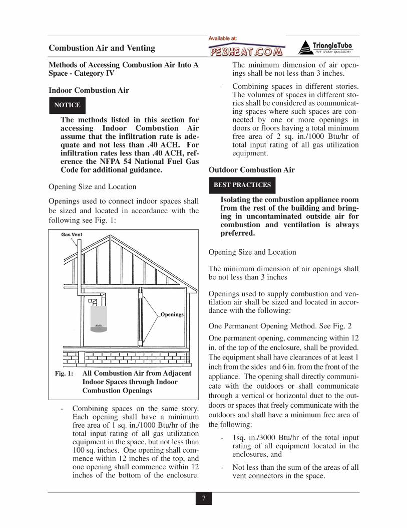
Openings used to connect indoor spaces shallbe sized and located in accordance with thefollowing see Fig. 1:
- Combining spaces on the same story.Each opening shall have a minimumfree area of 1 sq. in./1000 Btu/hr of thetotal input rating of all gas utilizationequipment in the space, but not less than100 sq. inches. One opening shall com-mence within 12 inches of the top, andone opening shall commence within 12inches of the bottom of the enclosure.
The minimum dimension of air open-ings shall be not less than 3 inches.
- Combining spaces in different stories.The volumes of spaces in different sto-ries shall be considered as communicat-ing spaces where such spaces are con-nected by one or more openings indoors or floors having a total minimumfree area of 2 sq. in./1000 Btu/hr oftotal input rating of all gas utilizationequipment.
Outdoor Combustion Air
Isolating the combustion appliance roomfrom the rest of the building and bring-ing in uncontaminated outside air forcombustion and ventilation is alwayspreferred.
Opening Size and Location
The minimum dimension of air openings shallbe not less than 3 inches
Openings used to supply combustion and ven-tilation air shall be sized and located in accor-dance with the following:
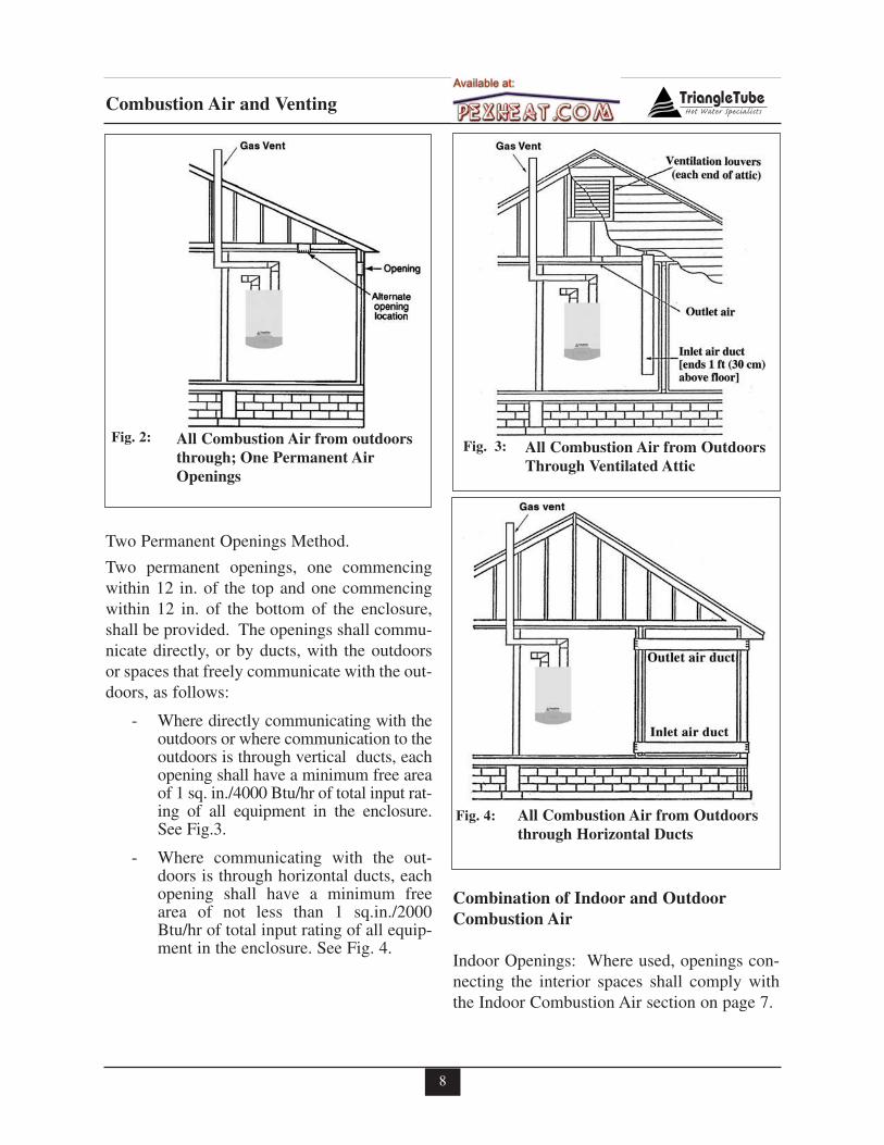
One Permanent Opening Method. See Fig. 2
One permanent opening, commencing within 12in. of the top of the enclosure, shall be provided.The equipment shall have clearances of at least 1inch from the sides and 6 in. from the front of theappliance. The opening shall directly communi-cate with the outdoors or shall communicatethrough a vertical or horizontal duct to the out-doors or spaces that freely communicate with theoutdoors and shall have a minimum free area ofthe following:
- 1sq. in./3000 Btu/hr of the total inputrating of all equipment located in theenclosures, and
- Not less than the sum of the areas of allvent connectors in the space.
BEST PRACTICES
NOTICE
All Combustion Air from AdjacentIndoor Spaces through IndoorCombustion Openings
Fig. 1:
8
Combustion Air and Venting
Two Permanent Openings Method.
Two permanent openings, one commencingwithin 12 in. of the top and one commencingwithin 12 in. of the bottom of the enclosure,shall be provided. The openings shall commu-nicate directly, or by ducts, with the outdoorsor spaces that freely communicate with the out-doors, as follows:
- Where directly communicating with theoutdoors or where communication to theoutdoors is through vertical ducts, eachopening shall have a minimum free areaof 1 sq. in./4000 Btu/hr of total input rat-ing of all equipment in the enclosure.See Fig.3.
- Where communicating with the out-doors is through horizontal ducts, eachopening shall have a minimum freearea of not less than 1 sq.in./2000Btu/hr of total input rating of all equip-ment in the enclosure. See Fig. 4.
Combination of Indoor and OutdoorCombustion Air
Indoor Openings: Where used, openings con-necting the interior spaces shall comply withthe Indoor Combustion Air section on page 7.
All Combustion Air from outdoorsthrough; One Permanent AirOpenings
Fig. 2: All Combustion Air from OutdoorsThrough Ventilated Attic
Fig. 3:
All Combustion Air from Outdoorsthrough Horizontal Ducts
Fig. 4:
9
Combustion Air and Venting
Outdoor Opening(s) Location. Outdoor open-ing(s) shall be located in accordance with theOutdoor Combustion Air section.
Outdoor Opening(s) Size. Outdoor opening(s) shallbe calculated in accordance with the following:
- The ratio of the interior spaces shall bethe available volume of all communi-cating spaces divided by the requiredvolume.
- The outdoor size reduction factor shallbe 1 minus the ratio of interior spaces.
- The minimum size of outdoor open-ing(s) calculated in accordance with theabove outdoor air section multiplied bythe reduction factor. The minimumdimension of air openings shall not beless than 3 in.
Do not install the PRESTIGE into a com-mon vent with other gas or oil appliances.This may cause flue gas spillage or appli-ance malfunction, resulting in possiblesevere personal injury, death or substan-tial property damage.
Combustion Air and Vent Piping
The PRESTIGE requires a Category IV vent-ing system, which is designed for pressurizedventing and condensate.
The PRESTIGE is certified per ANSI Z21.13as a Category IV or Direct Vent (sealed com-bustion) appliance. A Category IV applianceutilizes uncontamined indoor or outdoor air(surrounding the appliance) for combustion. ADirect Vent appliance utilizes uncontaminatedoutdoor air (piped directly to the appliance) forcombustion.
In order to reduce the potential risksassociated with indoor contaminates(listed on page 5), flammable vaporsand tight housing construction (little orno infiltration air), it is recommendedto pipe uncontaminated combustion airdirectly from the outdoors to the appli-ance. This practice also promotes highersystem efficiency by reducing heatedindoor air from being exhausted fromthe house and replaced by cold infiltra-tion air into the house.
Install combustion air and vent pipe asdetailed in the PRESTIGE Vent Sup-plement included in the boiler installa-tion envelope.
Verify installed combustion air and ventpiping are sealed gas tight and meet allprovided instructions and applicablecodes, failure to comply will result insevere personal injury of death.
DANGER
NOTICE
BEST PRACTICES
DANGER
10
Combustion Air and Venting
Removal of an Existing Boiler from aCommon Vent System
When an existing boiler is removed from acommon venting system, the common ventingsystem is likely to be too large for properventing of the remaining appliances. At thetime of removal of an existing boiler, the fol-lowing steps shall be followed with eachappliance remaining connected to the com-mon venting system placed in operation,while the other appliances remaining con-nected to the common venting system are notin operation.
1. Seal any unused openings in the commonventing system.
2. Visually inspect the venting system forproper size and horizontal pitch and deter-mine there is no blockage or restriction,leakage, corrosion and other deficiencieswhich could cause an unsafe condition.
3. Insofar as is practical, close all buildingdoors and windows and all doors betweenthe space in which the appliances remain-ing connected to the common venting sys-tem are located and other spaces of thebuilding. Turn on clothes dryers and anyappliance not connected to the commonventing system. Turn on any exhaust fans,such as range hoods and bathroomexhausts, so they will operate at maximumspeed. Do not operate a summer exhaustfan. Close fireplace dampers.
4. Place in operation the appliance beinginspected. Follow the lighting instructions.Adjust thermostat so appliance will operatecontinuously.
5. Test for spillage at the draft hood reliedopening after 5 minutes of main burneroperation. Use the flame of a match or can-dle, or smoke from a cigarette, cigar or pipe.
6. After it has been determined that eachappliance remaining connected to the com-mon venting system properly vents whentested as outlined above, return doors, win-dows, exhaust fans, fireplace dampers, andany other gas-burning appliance to theirprevious condition of use.
7. Any improper operation of the commonventing system should be corrected so theinstallation conforms with the NationalFuel Gas Code, ANSI Z223.1/NFPA 54and/or CAN/CGA B149, Installation codes.When resizing any portion of the commonventing system, the common venting sys-tem should be resized to approach the min-imum size as determined using the appro-priate tables in Part II of the National FuelGas Code ANSI Z223.1/NFPA 54 and/orCAN/CGA B149, Installation codes.
Do not install the PRESTIGE into a com-mon vent with other gas or oil appliances.This may cause flue gas spillage or appli-ance malfunction, resulting in possiblesevere personal injury, death or substan-tial property damage.
DANGER
BEST PRACTICES
11
Combustion Air and Venting
For direct-vent appliances, mechanical-vent heating appliances or domestic hotwater equipment, where the bottom of thevent terminal and the air intake is installedbelow four feet above grade the followingrequirements must be satisfied:
1. If there is not one already present, oneach floor level where there are bed-room(s), a carbon monoxide detectorand alarm shall be placed in the livingarea outside the bedroom(s). The car-bon monoxide detector shall complywith NFPA 720 (2005 Edition).
2. A carbon monoxide detector shall alsobe located in the room that houses theappliance or equipment and shall:
a. Be powered by the same electricalcircuit as the appliance or equip-ment such that only one serviceswitch services both the applianceand the carbon monoxide detector;
b. Have battery back-up power;
c. Meet ANSI/UL 2034 Standards andcomply with NFPA 720 (2005Edition); and
d. Have been approved and listed bythe Nationally Recognized TestingLaboratory as recognized under 527CMR.
3. A Product-approved vent terminal mustbe used, and if applicable, a Product-approved air intake must be used.Installation shall be in strict compliancewith the manufacturer’s instructions. Acopy of the installation instructionsshall remain with the appliance orequipment at the completion of theinstallation.
4. A metal or plastic identification plateshall be mounted at the exterior of thebuilding, four feet directly above thelocation of vent terminal. The plateshall be of sufficient size to be easilyread from a distance of eight feet away,and read “Gas Vent Directly Below”.
Installer must provide tag identificationplate and ensure the lettering meets coderequirements.
For direct-vent appliances, mechanical-vent heating appliances or domestic hotwater equipment, where the bottom of thevent terminal and the air intake is installedabove four feet above grade the followingrequirements must be satisfied:
1. If there is not one already present, oneach floor level where there are bed-room(s), a carbon monoxide detectorand alarm shall be placed in the livingarea outside the bedroom(s). The car-bon monoxide detector shall complywith NFPA 720 (2005 Edition).
2. A carbon monoxide detector shall:
a. Be located in the room that housesthe appliances or equipment;
b. Be either hard wired or batterypowered or both; and
c. Shall comply with NFPA 720 (2005Edition)
3. A Product-approved vent terminal mustbe used, and if applicable, a Product-approved air intake must be used.Installation shall be in strict compliancewith the manufacturer’s instructions. Acopy of the installation instructionsshall remain with the appliance orequipment at the completion of theinstallation.
NOTICE
Commonwealth of Massachusetts Installations Only
12
Unit Preparations
SECTION III - Unit Preparations
Handling Instructions
The PRESTIGE is generally easier to handleand maneuver once removed from the shippingcarton.
To remove the shipping carton:
Use care not to lift the unit from, or placethe unit on the front plastic controlpanel, damage can occur. Use care not todrop, bump or rotate the boiler upsidedown, as damage to the boiler will result.
1. Remove any shipping straps and open theside of the shipping carton.
2. Slide the unit with the foam inserts out ofthe carton.
3. Discard all packing materials.
Wall Mounting Installation
1. The PRESTIGE should be wall mountedusing the bracket provided with the boiler.The PRESTIGE is not designed for floorinstallation. If floor installation is requiredan optional floor stand is available throughTriangle Tube.
The wall used for mounting the PRES-TIGE must be vertically plumbed andcapable of supporting a minimum 175pounds [80 kg]. Failure to comply withthese requirements could result in per-sonal injury, death or substantial prop-erty damage.
Wall Mounting Guidelines
1. The wall-mounting bracket is designed forstud spacing of 12 inch or 16 inch on cen-ters. For unconventional stud spacing, asolid / secure mounting surface must beprovided for installation of the bracket.
2. For applications using wood studs, installthe bracket using the lag screws providedwith the boiler. Ensure both lag screws areinstalled securely in the studs.
3. For applications using metal studs, installthe bracket to the studs using 3/16” togglebolts and washers.
4. DO NOT mount or attempt to mount thewall bracket to hollow sheet rock or lathewalls using anchors. Only install boiler tostuds or equivalent wood structure.
5. For applications using solid walls (rock,concrete, brick, cinder block, etc.), installthe wall bracket using anchors (doubleexpansion shields) and bolts with washersprovided with the boiler.
6. The boiler is too heavy and bulky for a sin-gle person to lift and attempt to mount; aminimum of 2 people is required formounting the boiler.
Use extreme care not to drop the boileror cause bodily injury while lifting ormounting the boiler onto the bracket.Once mounted verify that the boiler issecurely attached to the bracket andwall. Failure to comply with the aboveguidelines could result in property dam-age, personal injury or death.
Wall Bracket Installation - Stud Walls
1. Locate the studs in the general area of theboiler placement.
2. Place the wall-mounting bracket on thewall centering the mounting slots with thestud centers and ensuring the upper edge ofthe bracket is away from the wall.
3. Level the bracket, while maintaining it’scentering with the studs and use a pencil tomark the location of the mounting slots.
WARNING
WARNING
CAUTION
13
Unit Preparations
4. Remove the bracket from the wall and drill1/4” diameter hole by 3” deep positioned inthe center of each mark. For applicationsusing metal studs and 3/16” toggle bolts,drill the required clearance hole.
5. Reposition the bracket onto the wall andalign mounting slots/holes. Insert the twolag screws provided (or toggle bolts formetal studs) through the mountingslots/holes and loosely tighten.
6. Level bracket and tighten screws (bolts formetal studs) securely making sure not toover-tighten to avoid damaging drywall orplaster.
Wall Bracket Installation - Solid Walls
1. Locate the general area of the boiler place-ment.
2. Place the wall-mounting bracket on thewall ensuring the upper edge of the bracketis away from the wall.
3. Level the bracket and use a pencil to markthe location of the mounting slots on thewall.
4. Remove the bracket from the wall and drilla 5/8” diameter hole by 1-3/8” deep posi-tioned in the center of each mark.
5. Install the anchors (provided) flush orslightly recessed in the drilled holes withthreaded side facing down.
6. Reposition the bracket on the wall andalign mounting slots/holes. Insert the twobolts (provided) through the mountingslots/holes and loosely tighten.
7. Level bracket and tighten bolts securely.
Boiler Mounting
1. Obtain assistance in lifting the boiler ontothe wall bracket.
2. Install the boiler making sure the boilermounting lip located along the upper edgeof the rear jacket panel engages the wall-mounting bracket. Ensure the boiler isseated properly and is secure.
Hydrostatic Pressure Test
Prior to permanently connecting water,gas supply or electrical supply, performa pressure hydrostatic test of the boilerwater connections to ensure all pipingconnections within the boiler enclosurewere not damaged during shipment.
Remove factory installed plugs on gasand water connections before installation.
Hydrostatic Test Preparation
Use a two-wrench method when tighten-ing fittings or piping onto the boiler con-nections. Use one wrench to prevent theboiler connection from twisting and thesecond wrench to tighten the fitting orpiping. Failure to support the boiler con-nection could damage the boiler and itsinternal piping.
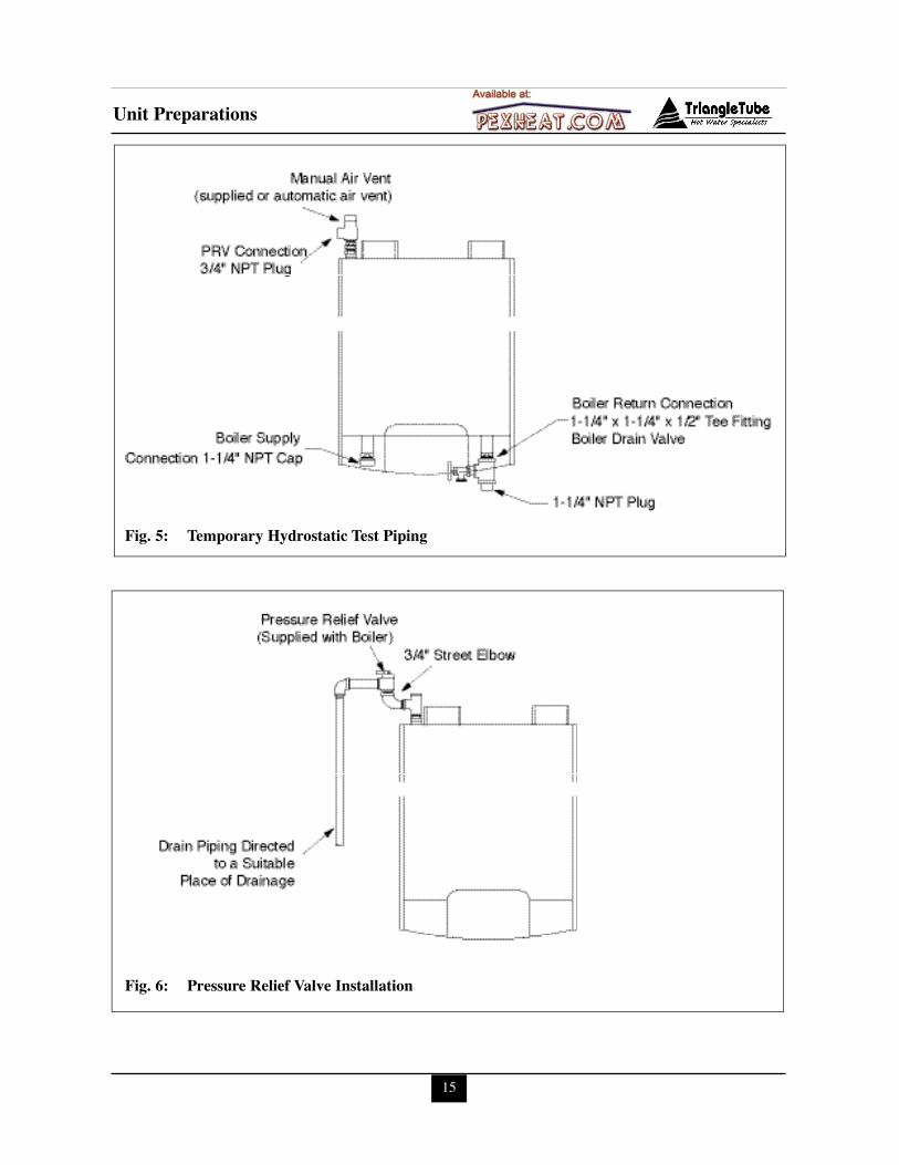
1. Temporarily plug the PRV connectionusing a 3/4” NPT plug. Use pipe dope spar-ingly to allow removal of the plug uponcompletion of the test.
2. Pipe the manual air vent (supplied) or anautomatic air vent onto the 1/2” connectionof the reducing tee located at the top of theunit, as shown in Fig. 5, page 15. The airvent will not be removed after the comple-tion of test, so ensure adequate pipe dope isapplied.
3. Temporarily cap the boiler supply and returnconnection as shown in Fig. 5, Page 15,using 1-1/4” NPT cap. Use pipe dope spar-ingly to allow removal of the caps uponcompletion of the test.
WARNING
NOTICE
BEST PRACTICES
14
Unit Preparations
4. On the primary return connection pipe a 1-1/4” x 1-1/4” x 1/2” tee fitting and the boil-er drain valve. The tee fitting and boilerdrain valve will not be removed after thecompletion of test, so ensure adequate pipedope is applied.
5. Temporarily plug the tee fitting on the boil-er return using a 1-1/4” NPT plug. Use pipedope sparingly to allow removal of the plugupon completion of the test.
6. Connect a hose to the boiler drain valve andconnect the other end to a fresh water sup-ply. Ensure the hose can be used as a drainhose upon completion of the test.
Hydrostatic Test Procedures
1. Open the air vent located on the 1/2 inchconnection of the reducing tee located atthe top of the unit, as shown in Fig. 5 page15, one full turn counter-clockwise.
2. Open the fresh water supply valve and thenopen the boiler drain valve slowly to fill theboiler with water.
The boiler will fill quickly as the totalwater volume is less than 5 gallons [ 19 L].
3. When the air vent begins to bleed water orstops releasing air, close the boiler drainvalve.
4. Close the air vent and slowly reopen theboiler drain valve until the test pressure onthe pressure gauge reaches a maximum 30psig.
Do not pressurize the boiler and its com-ponents above 30 psig. Damage to theheat exchanger and the boiler compo-nents could occur resulting in personalinjury, death or substantial propertydamage.
5. Allow the test pressure to remain for 10minutes.
Do not leave the unit unattended whilepressurized. A cold water fill couldexpand and cause excessive pressure,resulting in severe personal injury, deathor substantial property damage.
6. Ensure constant gauge pressure has beenmaintained throughout the 10 minute test.Check for leaks at all joints. Repair iffound.
Leaks must be repaired immediatelywhen detected. Failure to repair leakscan damage the unit, resulting in sub-stantial property damage.
7. Check continuity using a voltmeter acrossthe terminals of the LWCO device. Thecontacts on the LWCO should be closed.See Item 5 Fig. 27 page 62 for location ofthe LWCO.
Completion of Hydrostatic Test and Draining
1. Disconnect the fill hose from the freshwater source and direct the hose to a suit-able place of drainage.
2. Open the boiler drain valve and completelydrain the unit. To aid in draining open theair vent.
3. Remove the hose from the boiler drainvalve when draining is complete.
4. Remove caps, plugs and any other pipingunless they will remain for use in the systempiping.
5. If the manual air vent remains ensure it isclosed.
WARNING
WARNING
WARNING
WARNING
Unit Preparations
15
Fig. 5: Temporary Hydrostatic Test Piping
Fig. 6: Pressure Relief Valve Installation
Boiler Piping
SECTION IV - Boiler Piping
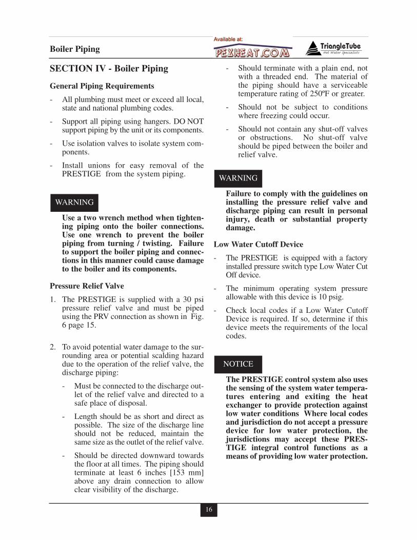
General Piping Requirements
- All plumbing must meet or exceed all local,state and national plumbing codes.
- Support all piping using hangers. DO NOTsupport piping by the unit or its components.
- Use isolation valves to isolate system com-ponents.
- Install unions for easy removal of thePRESTIGE from the system piping.
Use a two wrench method when tighten-ing piping onto the boiler connections.Use one wrench to prevent the boilerpiping from turning / twisting. Failureto support the boiler piping and connec-tions in this manner could cause damageto the boiler and its components.
Pressure Relief Valve
1. The PRESTIGE is supplied with a 30 psipressure relief valve and must be pipedusing the PRV connection as shown in Fig.6 page 15.
2. To avoid potential water damage to the sur-rounding area or potential scalding hazarddue to the operation of the relief valve, thedischarge piping:
- Must be connected to the discharge out-let of the relief valve and directed to asafe place of disposal.
- Length should be as short and direct aspossible. The size of the discharge lineshould not be reduced, maintain thesame size as the outlet of the relief valve.
- Should be directed downward towardsthe floor at all times. The piping shouldterminate at least 6 inches [153 mm]above any drain connection to allowclear visibility of the discharge.
- Should terminate with a plain end, notwith a threaded end. The material ofthe piping should have a serviceabletemperature rating of 250ºF or greater.
- Should not be subject to conditionswhere freezing could occur.
- Should not contain any shut-off valvesor obstructions. No shut-off valveshould be piped between the boiler andrelief valve.
Failure to comply with the guidelines oninstalling the pressure relief valve anddischarge piping can result in personalinjury, death or substantial propertydamage.
Low Water Cutoff Device
- The PRESTIGE is equipped with a factoryinstalled pressure switch type Low Water CutOff device.
- The minimum operating system pressureallowable with this device is 10 psig.
- Check local codes if a Low Water CutoffDevice is required. If so, determine if thisdevice meets the requirements of the localcodes.
The PRESTIGE control system also usesthe sensing of the system water tempera-tures entering and exiting the heatexchanger to provide protection againstlow water conditions Where local codesand jurisdiction do not accept a pressuredevice for low water protection, thejurisdictions may accept these PRES-TIGE integral control functions as ameans of providing low water protection.
NOTICE
WARNING
WARNING
16
Boiler Piping
Additional Limit Control
If a separate LWCO device is required by cer-tain local jurisdictions or when the boiler isinstalled above the system piping, the follow-ing guidelines must be followed:
- The LWCO device must be designedfor water installations, electrode probe-type is recommended.
- The LWCO device must be installed ina tee connection on the boiler supplypiping above the boiler.
- Wiring of the LWCO device to thePRESTIGE is done directly onto the24V terminal strip, reference Fig. 20page 32 for available terminals for anexternal limit (manual or auto reset).
If the installation is to comply with ASME orCanadian requirements, an additional hightemperature limit may be needed. Consultlocal code requirements to determine compli-ance. The limit should be installed as follows:
- Install the limit in the boiler supply pip-ing between the boiler and any isolationvalve.
- Maximum set point for the limit is194ºF.
- For wiring of the limit reference Fig. 20,page 32, using the external limit/manualreset terminals on the 24V terminal strip.This will provide a "hard" lockoutrequiring a manual reset of the control.
Backflow Preventer
- Use a backflow preventer valve in themake-up water supply to the unit asrequired by local codes.
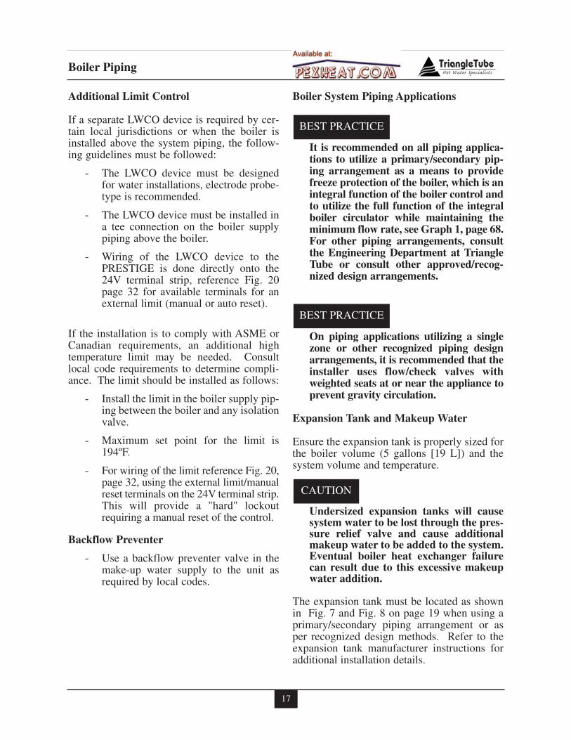
Boiler System Piping Applications
It is recommended on all piping applica-tions to utilize a primary/secondary pip-ing arrangement as a means to providefreeze protection of the boiler, which is anintegral function of the boiler control andto utilize the full function of the integralboiler circulator while maintaining theminimum flow rate, see Graph 1, page 68.For other piping arrangements, consultthe Engineering Department at TriangleTube or consult other approved/recog-nized design arrangements.
On piping applications utilizing a singlezone or other recognized piping designarrangements, it is recommended that theinstaller uses flow/check valves withweighted seats at or near the appliance toprevent gravity circulation.
Expansion Tank and Makeup Water
Ensure the expansion tank is properly sized forthe boiler volume (5 gallons [19 L]) and thesystem volume and temperature.
Undersized expansion tanks will causesystem water to be lost through the pres-sure relief valve and cause additionalmakeup water to be added to the system.Eventual boiler heat exchanger failurecan result due to this excessive makeupwater addition.
The expansion tank must be located as shownin Fig. 7 and Fig. 8 on page 19 when using aprimary/secondary piping arrangement or asper recognized design methods. Refer to theexpansion tank manufacturer instructions foradditional installation details.
CAUTION
BEST PRACTICE
BEST PRACTICE
17
Boiler Piping
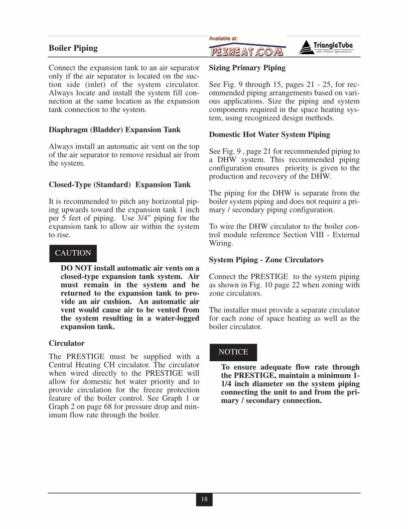
Connect the expansion tank to an air separatoronly if the air separator is located on the suc-tion side (inlet) of the system circulator.Always locate and install the system fill con-nection at the same location as the expansiontank connection to the system.
Diaphragm (Bladder) Expansion Tank
Always install an automatic air vent on the topof the air separator to remove residual air fromthe system.
Closed-Type (Standard) Expansion Tank
It is recommended to pitch any horizontal pip-ing upwards toward the expansion tank 1 inchper 5 feet of piping. Use 3/4” piping for theexpansion tank to allow air within the systemto rise.
DO NOT install automatic air vents on aclosed-type expansion tank system. Airmust remain in the system and bereturned to the expansion tank to pro-vide an air cushion. An automatic airvent would cause air to be vented fromthe system resulting in a water-loggedexpansion tank.
Circulator
The PRESTIGE must be supplied with aCentral Heating CH circulator. The circulatorwhen wired directly to the PRESTIGE willallow for domestic hot water priority and toprovide circulation for the freeze protectionfeature of the boiler control. See Graph 1 orGraph 2 on page 68 for pressure drop and min-imum flow rate through the boiler.
Sizing Primary Piping
See Fig. 9 through 15, pages 21 - 25, for rec-ommended piping arrangements based on vari-ous applications. Size the piping and systemcomponents required in the space heating sys-tem, using recognized design methods.
Domestic Hot Water System Piping
See Fig. 9 , page 21 for recommended piping toa DHW system. This recommended pipingconfiguration ensures priority is given to theproduction and recovery of the DHW.
The piping for the DHW is separate from theboiler system piping and does not require a pri-mary / secondary piping configuration.
To wire the DHW circulator to the boiler con-trol module reference Section VIII - ExternalWiring.
System Piping - Zone Circulators
Connect the PRESTIGE to the system pipingas shown in Fig. 10 page 22 when zoning withzone circulators.
The installer must provide a separate circulatorfor each zone of space heating as well as theboiler circulator.
To ensure adequate flow rate throughthe PRESTIGE, maintain a minimum 1-1/4 inch diameter on the system pipingconnecting the unit to and from the pri-mary / secondary connection.
NOTICE
CAUTION
18
19
Boiler Piping
Max.12"
Boiler
SupplySystem
ReturnSystem
ColdWater Fill
BoilerSupply Return
7
10
1
2
3
546
66
11 12
71
10
9
8
4
3
6
66
Cold
W ater Fill
BoilerSupply
Minimum3/4" Piping
BoilerReturn
ReturnSystem
SupplySystem
Max.12"
11 12
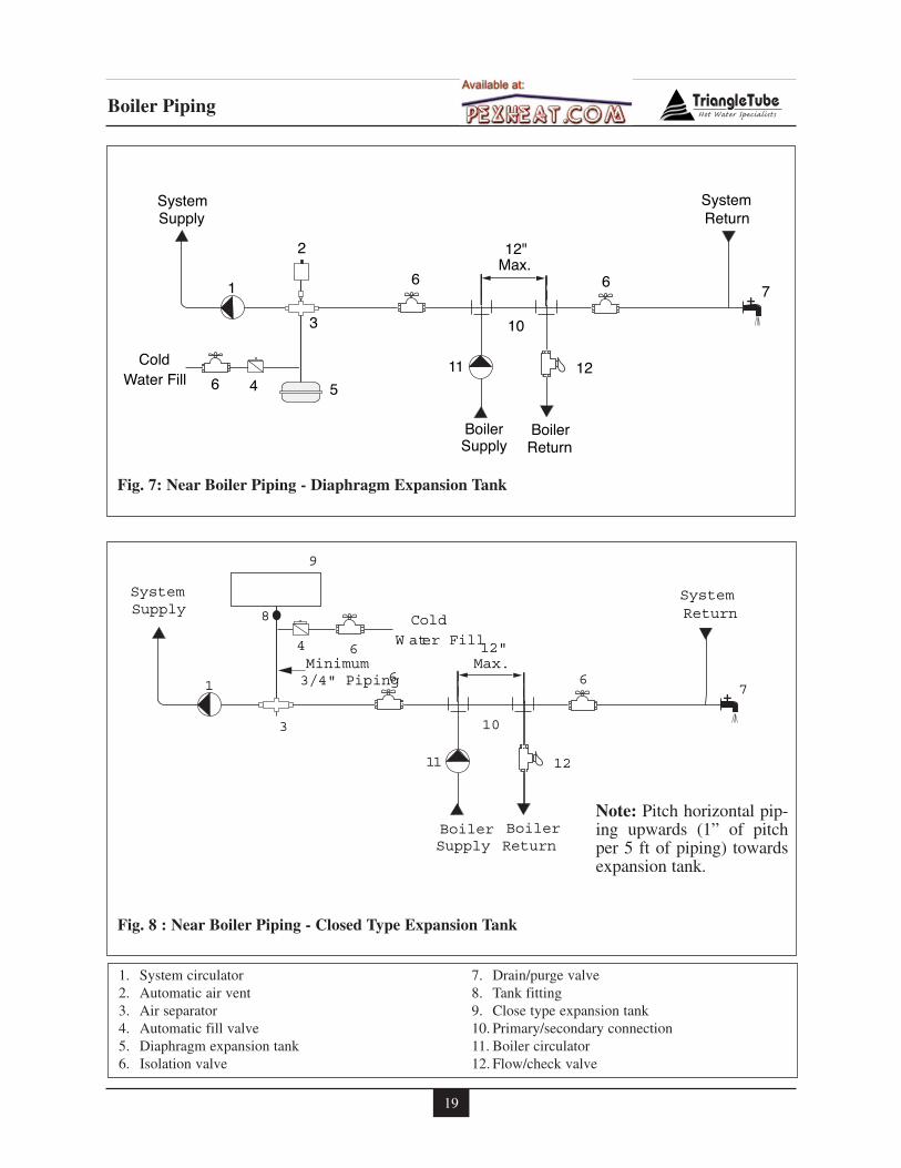
Fig. 8 : Near Boiler Piping - Closed Type Expansion Tank
Fig. 7: Near Boiler Piping - Diaphragm Expansion Tank
1. System circulator2. Automatic air vent3. Air separator4. Automatic fill valve5. Diaphragm expansion tank6. Isolation valve
7. Drain/purge valve8. Tank fitting9. Close type expansion tank10. Primary/secondary connection 11. Boiler circulator12. Flow/check valve
Note: Pitch horizontal pip-ing upwards (1” of pitchper 5 ft of piping) towardsexpansion tank.
20
Boiler Piping
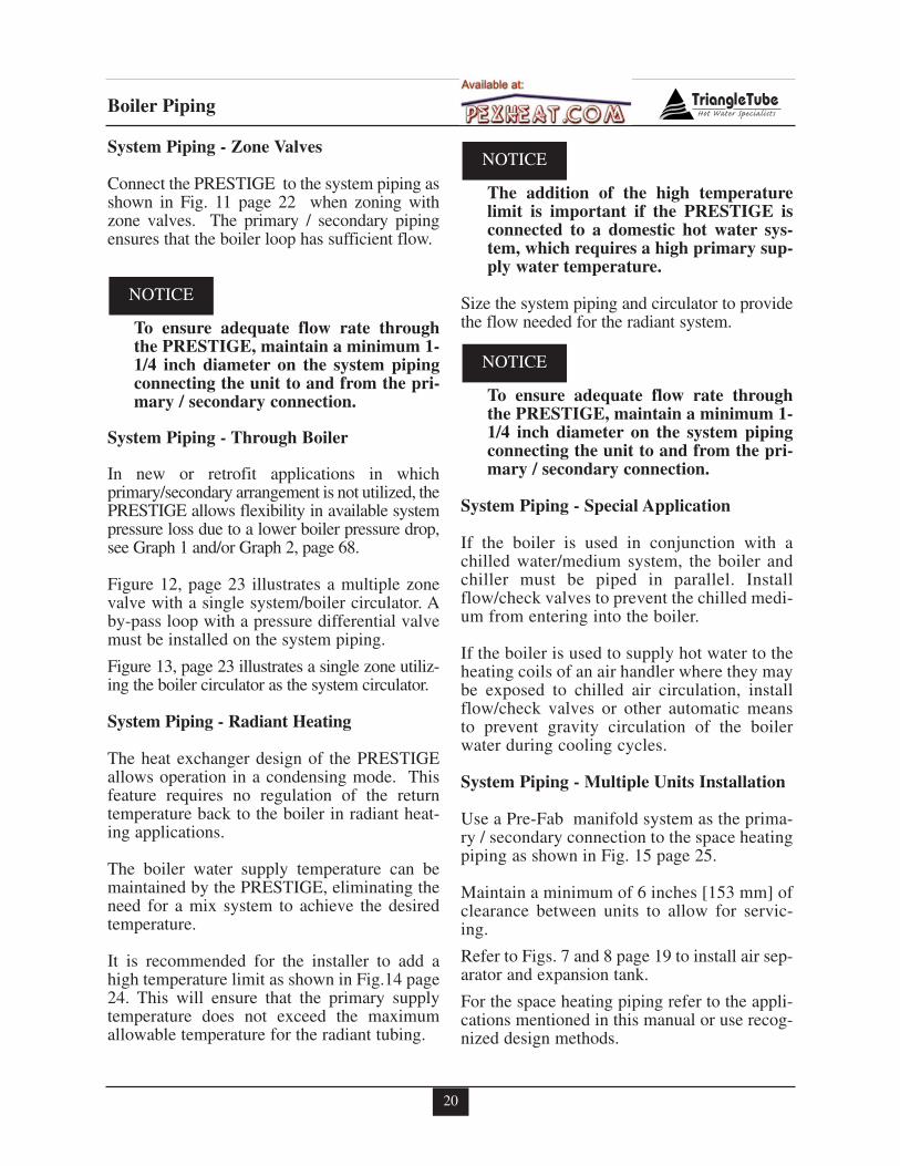
System Piping - Zone Valves
Connect the PRESTIGE to the system piping asshown in Fig. 11 page 22 when zoning withzone valves. The primary / secondary pipingensures that the boiler loop has sufficient flow.
To ensure adequate flow rate throughthe PRESTIGE, maintain a minimum 1-1/4 inch diameter on the system pipingconnecting the unit to and from the pri-mary / secondary connection.
System Piping - Through Boiler
In new or retrofit applications in whichprimary/secondary arrangement is not utilized, thePRESTIGE allows flexibility in available systempressure loss due to a lower boiler pressure drop,see Graph 1 and/or Graph 2, page 68.
Figure 12, page 23 illustrates a multiple zonevalve with a single system/boiler circulator. Aby-pass loop with a pressure differential valvemust be installed on the system piping.
Figure 13, page 23 illustrates a single zone utiliz-ing the boiler circulator as the system circulator.
System Piping - Radiant Heating
The heat exchanger design of the PRESTIGEallows operation in a condensing mode. Thisfeature requires no regulation of the returntemperature back to the boiler in radiant heat-ing applications.
The boiler water supply temperature can bemaintained by the PRESTIGE, eliminating theneed for a mix system to achieve the desiredtemperature.
It is recommended for the installer to add ahigh temperature limit as shown in Fig.14 page24. This will ensure that the primary supplytemperature does not exceed the maximumallowable temperature for the radiant tubing.
The addition of the high temperaturelimit is important if the PRESTIGE isconnected to a domestic hot water sys-tem, which requires a high primary sup-ply water temperature.
Size the system piping and circulator to providethe flow needed for the radiant system.
To ensure adequate flow rate throughthe PRESTIGE, maintain a minimum 1-1/4 inch diameter on the system pipingconnecting the unit to and from the pri-mary / secondary connection.
System Piping - Special Application
If the boiler is used in conjunction with achilled water/medium system, the boiler andchiller must be piped in parallel. Installflow/check valves to prevent the chilled medi-um from entering into the boiler.
If the boiler is used to supply hot water to theheating coils of an air handler where they maybe exposed to chilled air circulation, installflow/check valves or other automatic meansto prevent gravity circulation of the boilerwater during cooling cycles.
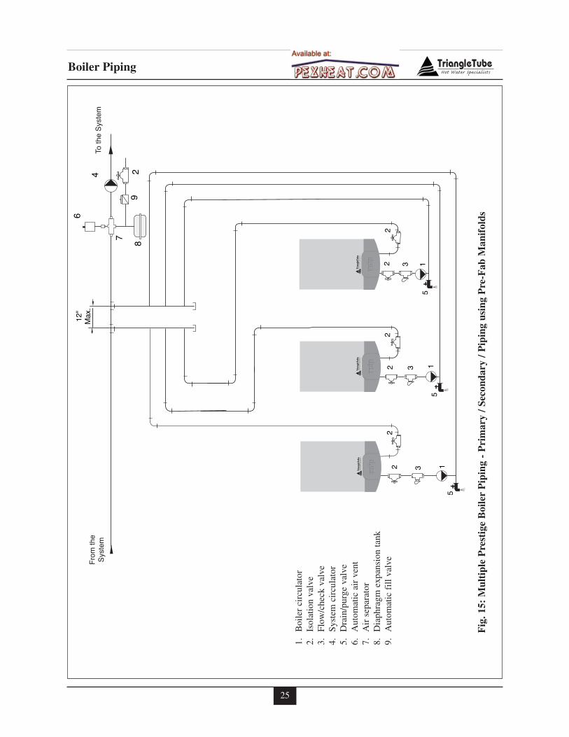
System Piping - Multiple Units Installation
Use a Pre-Fab manifold system as the prima-ry / secondary connection to the space heatingpiping as shown in Fig. 15 page 25.
Maintain a minimum of 6 inches [153 mm] ofclearance between units to allow for servic-ing.
Refer to Figs. 7 and 8 page 19 to install air sep-arator and expansion tank.
For the space heating piping refer to the appli-cations mentioned in this manual or use recog-nized design methods.
NOTICE
NOTICE
NOTICE
21
Boiler Piping
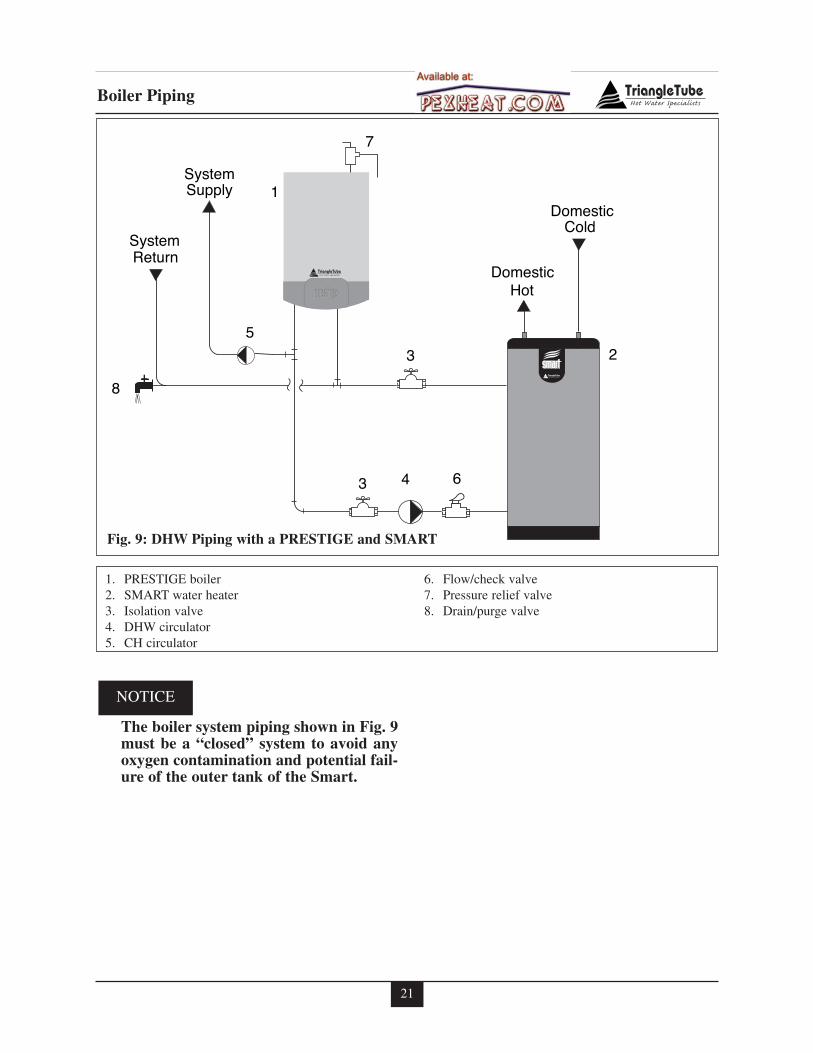
1. PRESTIGE boiler2. SMART water heater3. Isolation valve4. DHW circulator 5. CH circulator
6. Flow/check valve7. Pressure relief valve8. Drain/purge valve
2
1
7
5
63
3
4
SupplySystem
System
Hot
ColdDomestic
DomesticReturn
8
Fig. 9: DHW Piping with a PRESTIGE and SMART
The boiler system piping shown in Fig. 9must be a “closed” system to avoid anyoxygen contamination and potential fail-ure of the outer tank of the Smart.
NOTICE
22
Boiler Piping
5
5
4
6
1
2
3
3
3
3
3
9
8
1011
4
4
4
4
44
Zone Load
Additional
7
6
Max.12"
Zone Load
2
6
5
5
4
6
1
3
12
9
8
1011
4
4
4
4
44
Zone Load
7
Additional
Max.12"
Zone Load
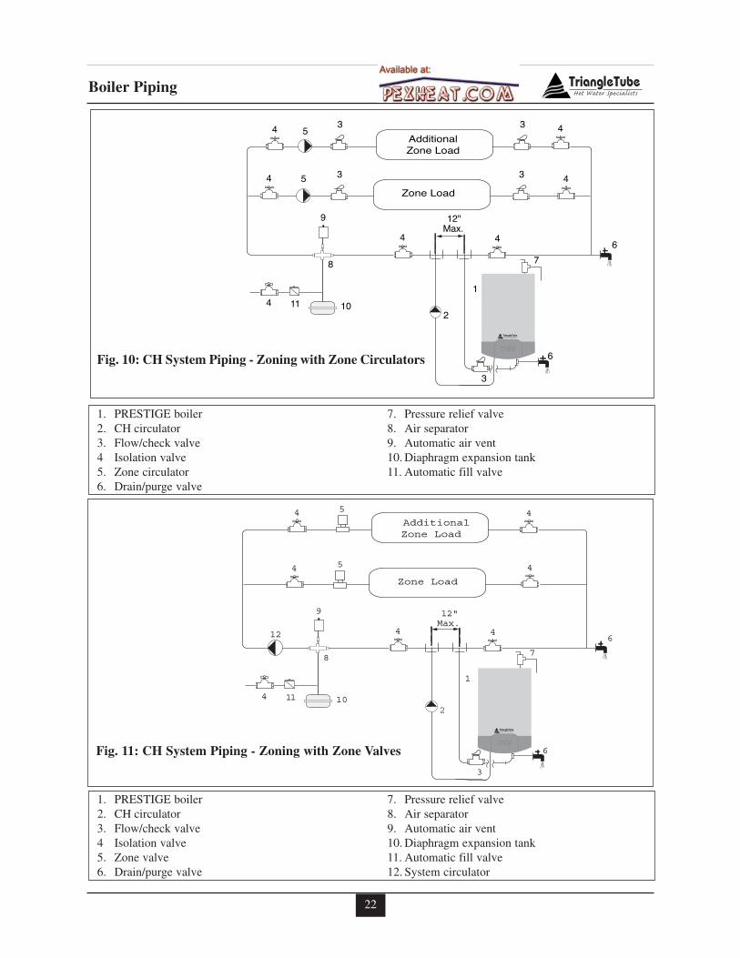
Fig. 10: CH System Piping - Zoning with Zone Circulators
1. PRESTIGE boiler2. CH circulator 3. Flow/check valve4 Isolation valve5. Zone circulator 6. Drain/purge valve
7. Pressure relief valve8. Air separator9. Automatic air vent10. Diaphragm expansion tank11. Automatic fill valve
Fig. 11: CH System Piping - Zoning with Zone Valves
1. PRESTIGE boiler2. CH circulator 3. Flow/check valve4 Isolation valve5. Zone valve6. Drain/purge valve
7. Pressure relief valve8. Air separator9. Automatic air vent10. Diaphragm expansion tank11. Automatic fill valve12. System circulator
23
Boiler Piping
12
7
6
4AdditionalZone Load
4 5
4
4
4
2
Zone Load
9
8
10114
5
12P
12
7
64
2
SingleZone load
9
8
10114
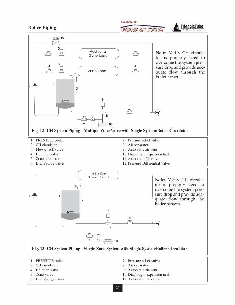
Fig. 12: CH System Piping - Multiple Zone Valve with Single System/Boiler Circulator
1. PRESTIGE boiler2. CH circulator 3. Flow/check valve4 Isolation valve5. Zone circulator 6. Drain/purge valve
7. Pressure relief valve8. Air separator9. Automatic air vent10. Diaphragm expansion tank11. Automatic fill valve12. Pressure Differential Valve
Fig. 13: CH System Piping - Single Zone System with Single System/Boiler Circulator
1. PRESTIGE boiler2. CH circulator 4 Isolation valve5. Zone valve6. Drain/purge valve
7. Pressure relief valve8. Air separator9. Automatic air vent10. Diaphragm expansion tank11. Automatic fill valve
Note: Verify CH circula-tor is properly sized toovercome the system pres-sure drop and provide ade-quate flow through theboiler system.
Note: Verify CH circula-tor is properly sized toovercome the system pres-sure drop and provide ade-quate flow through theboiler system.
24
Boiler Piping
2
5
5
4
6
1
3
1312
9
8
1011
4
4
4
Radiant Zone
Additional
4
44
6
7
Radiant Zone
Max.12"
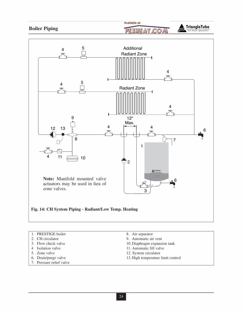
Note: Manifold mounted valveactuators may be used in lieu ofzone valves.
1. PRESTIGE boiler2. CH circulator 3. Flow check valve4 Isolation valve5. Zone valve6. Drain/purge valve7. Pressure relief valve
8. Air separator9. Automatic air vent10. Diaphragm expansion tank11. Automatic fill valve12. System circulator13. High temperature limit control
Fig. 14: CH System Piping - Radiant/Low Temp. Heating
25
Boiler Piping
33
22
2
3
22
2
Fro
mth
eS
yste
m
5
55
1
11
Toth
eS
yste
m4
6
7
89
2
12"
Max
.
1.B
oile
rci
rcul
ator
2.Is
olat
ion
valv
e3.
Flow
/che
ckva
lve
4.Sy
stem
circ
ulat
or5.
Dra
in/p
urge
valv
e6.
Aut
omat
icai
rve
nt7.
Air
sepa
rato
r8.
Dia
phra
gmex
pans
ion
tank
9.A
utom
atic
fill
valv
e
Fig
.15:
Mul
tipl
eP
rest
ige
Boi
ler
Pip
ing
-P
rim
ary
/Sec
onda
ry/P
ipin
gus
ing
Pre
-Fab
Man
ifol
ds
26
SECTION V - Installing Vent /Combustion Air & Condensate Drain
Installing Vent and Combustion Air
The PRESTIGE must be vented andsupplied with combustion air as shownin the PRESTIGE Venting Supplement,which is included in the installationenvelope. Once installation is complet-ed, inspect the vent and combustion airsystem thoroughly to ensure systems areairtight and comply with the instruc-tions given in the venting supplementand are within all requirements ofapplicable codes. Failure to comply withthe installation requirements on theventing and combustion air piping willcause severe personal injury or death.
Installing Condensate Drain Assembly
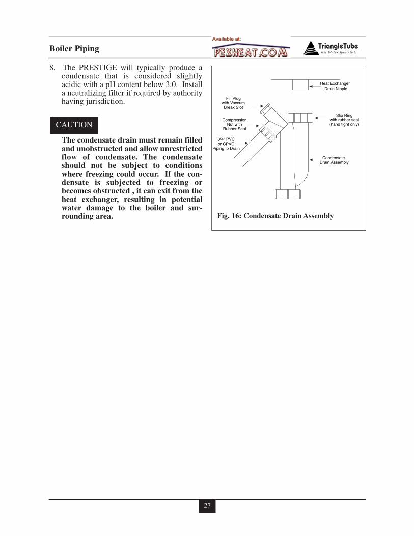
1. Locate the condensate drain assembly andinstall as shown in Fig. 16 page 27.
The installer may want to fill the con-densate trap with water prior to assem-bling on the unit.
2. Remove the slip ring and rubber seal fromthe condensate drain assembly and slideover the heat exchanger drain nipple.Connect the condensate drain assembly tothe slip ring and tighten. Hand tight only.
3. Remove the compression nut and rubberseal from the drain outlet.
4. Using 3/4” x 2’ flexible PVC tube provid-ed, slide the compression nut and rubberseal over the pipe.
The use of 3/4” PVC or CPVC pipe isalso acceptable. If 3/4” pipe is useddeburr and chamfer pipe to allow mat-ing onto the drain assembly.
5. Thread the rubber seal into the compres-sion nut to ease installation of the pipe tothe drain assembly.
6. Seat the pipe onto the drain assembly andtighten the compression nut. Hand tightonly!
The installer may opt to using 13/16" IDtubing in lieu of rigid piping.
The drain line materials must be anapproved material by the authority hav-ing jurisdiction. In absence of suchauthority, PVC and CPVC piping mustcomply with ASTM D1785 or D2845.The cement and primer used on the pip-ing must comply with ASME D2564 orF493. For installations in Canada, useCSA or ULC certified PVC or CPVCpipe, fittings and cement/primer.
7. Continue the pipe from the drain assemblyto a floor drain or condensate pump.
When selecting and installing a conden-sate pump, ensure the pump is approvedfor use with condensing boilers and fur-naces. The pump should be equippedwith an overflow switch to prevent prop-erty damage from potential condensatespillage.
NOTICE
NOTICE
NOTICE
NOTICE
NOTICE
DANGER
27
Boiler Piping
8. The PRESTIGE will typically produce acondensate that is considered slightlyacidic with a pH content below 3.0. Installa neutralizing filter if required by authorityhaving jurisdiction.
The condensate drain must remain filledand unobstructed and allow unrestrictedflow of condensate. The condensateshould not be subject to conditionswhere freezing could occur. If the con-densate is subjected to freezing orbecomes obstructed , it can exit from theheat exchanger, resulting in potentialwater damage to the boiler and sur-rounding area.
CAUTION
Condensate Drain Assembly
Slip Ringwith rubber seal(hand tight only)
3/4" PVCor CPVC
Piping to Drain
CompressionNut with
Rubber Seal
Fill Plugwith VaccumBreak Slot
Heat ExchangerDrain Nipple
Fig. 16: Condensate Drain Assembly
28
Gas Piping
SECTION VI - Gas Piping
Gas Supply Piping Connection
The gas supply piping must be installedin accordance to all applicable local,state and national codes and utilityrequirements.
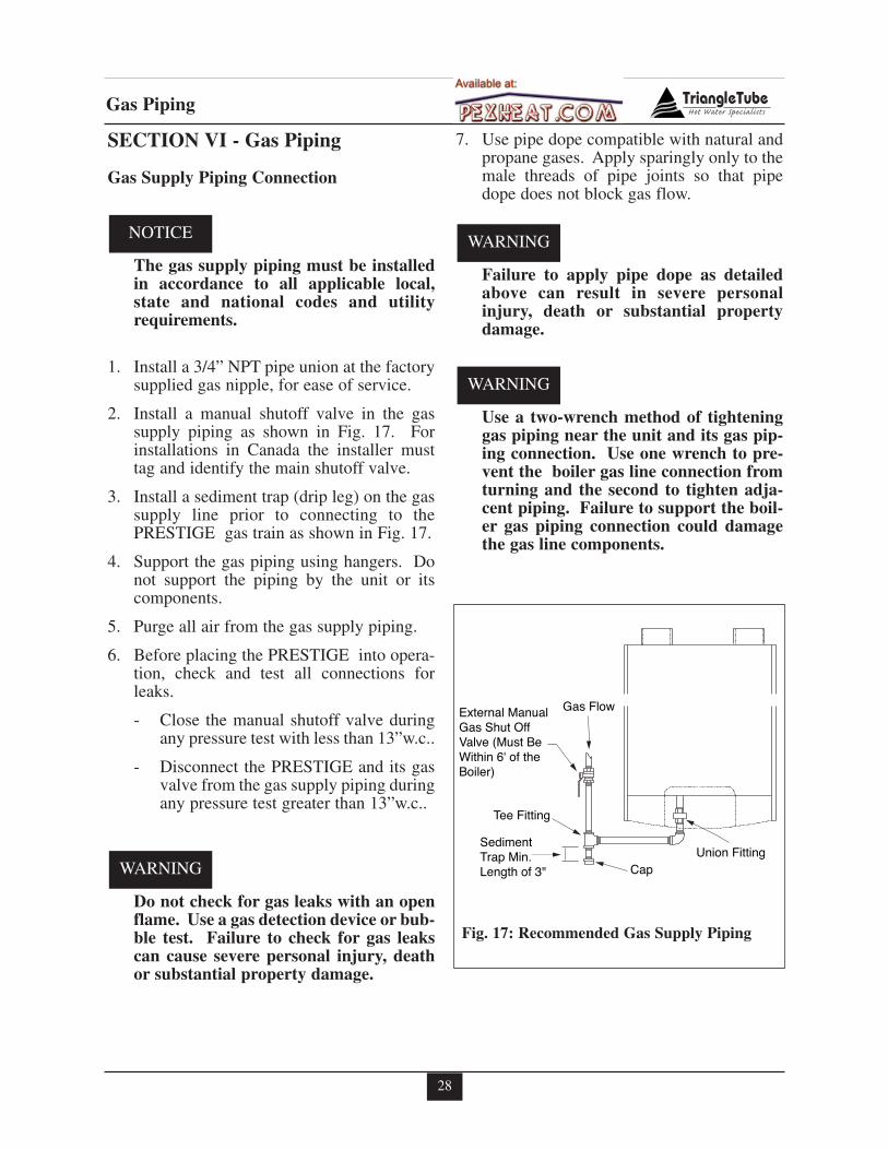
1. Install a 3/4” NPT pipe union at the factorysupplied gas nipple, for ease of service.
2. Install a manual shutoff valve in the gassupply piping as shown in Fig. 17. Forinstallations in Canada the installer musttag and identify the main shutoff valve.
3. Install a sediment trap (drip leg) on the gassupply line prior to connecting to thePRESTIGE gas train as shown in Fig. 17.
4. Support the gas piping using hangers. Donot support the piping by the unit or itscomponents.
5. Purge all air from the gas supply piping.
6. Before placing the PRESTIGE into opera-tion, check and test all connections forleaks.
- Close the manual shutoff valve duringany pressure test with less than 13”w.c..
- Disconnect the PRESTIGE and its gasvalve from the gas supply piping duringany pressure test greater than 13”w.c..
Do not check for gas leaks with an openflame. Use a gas detection device or bub-ble test. Failure to check for gas leakscan cause severe personal injury, deathor substantial property damage.
7. Use pipe dope compatible with natural andpropane gases. Apply sparingly only to themale threads of pipe joints so that pipedope does not block gas flow.
Failure to apply pipe dope as detailedabove can result in severe personalinjury, death or substantial propertydamage.
Use a two-wrench method of tighteninggas piping near the unit and its gas pip-ing connection. Use one wrench to pre-vent the boiler gas line connection fromturning and the second to tighten adja-cent piping. Failure to support the boil-er gas piping connection could damagethe gas line components.
WARNING
WARNING
WARNING
NOTICE
Sediment Trap Min. Length of 3"
Union FittingCap
Tee Fitting
External ManualGas Shut OffValve (Must BeWithin 6' of the Boiler)
Gas Flow
Fig. 17: Recommended Gas Supply Piping
29
Gas Piping
NATURAL GAS
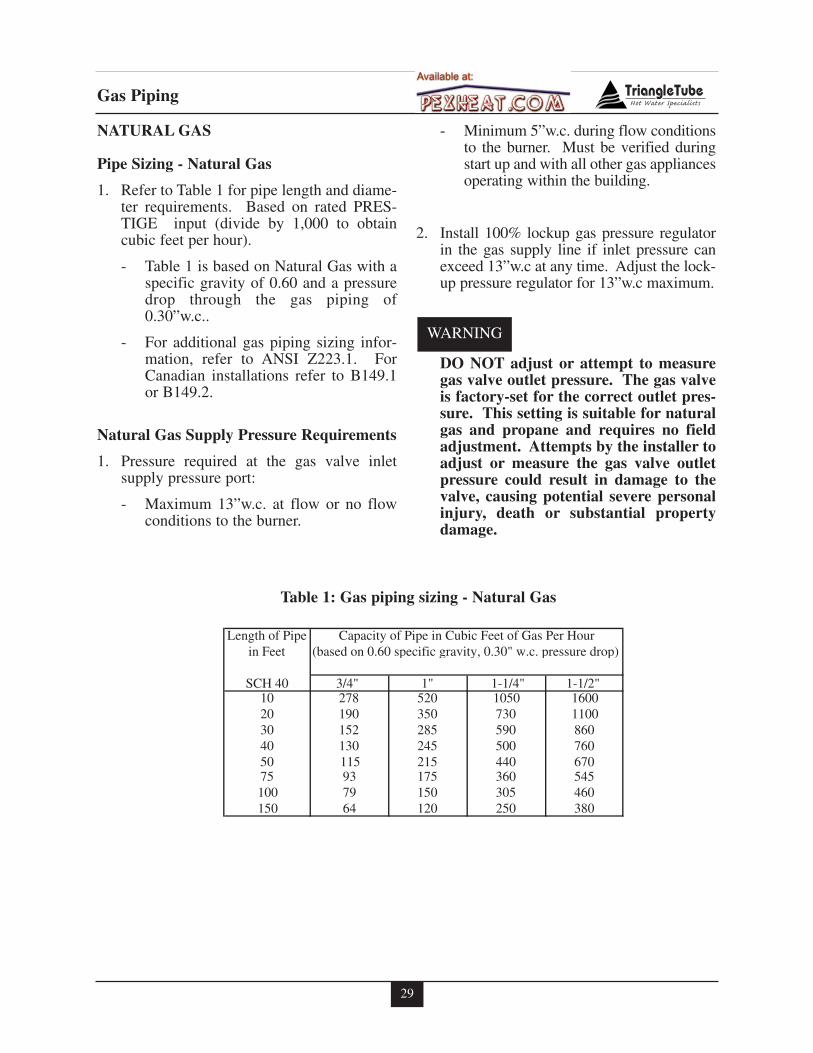
Pipe Sizing - Natural Gas
1. Refer to Table 1 for pipe length and diame-ter requirements. Based on rated PRES-TIGE input (divide by 1,000 to obtaincubic feet per hour).
- Table 1 is based on Natural Gas with aspecific gravity of 0.60 and a pressuredrop through the gas piping of0.30”w.c..
- For additional gas piping sizing infor-mation, refer to ANSI Z223.1. ForCanadian installations refer to B149.1or B149.2.
Natural Gas Supply Pressure Requirements
1. Pressure required at the gas valve inletsupply pressure port:
- Maximum 13”w.c. at flow or no flowconditions to the burner.
- Minimum 5”w.c. during flow conditionsto the burner. Must be verified duringstart up and with all other gas appliancesoperating within the building.
2. Install 100% lockup gas pressure regulatorin the gas supply line if inlet pressure canexceed 13”w.c at any time. Adjust the lock-up pressure regulator for 13”w.c maximum.
DO NOT adjust or attempt to measuregas valve outlet pressure. The gas valveis factory-set for the correct outlet pres-sure. This setting is suitable for naturalgas and propane and requires no fieldadjustment. Attempts by the installer toadjust or measure the gas valve outletpressure could result in damage to thevalve, causing potential severe personalinjury, death or substantial propertydamage.
WARNING
Length of Pipein Feet (based on 0.60 specific gravity, 0.30" w.c. pressure drop)
SCH 40 3/4" 1" 1-1/4" 1-1/2"10 278 520 1050 160020 190 350 730 110030 152 285 590 86040 130 245 500 76050 115 215 440 67075 93 175 360 545100 79 150 305 460150 64 120 250 380
Capacity of Pipe in Cubic Feet of Gas Per Hour
Table 1: Gas piping sizing - Natural Gas
30
Gas Piping
PROPANE GAS
Pipe Sizing - Propane Gas
1. Contact the local propane gas supplier forrecommended sizing of piping, tanks and100% lockup gas regulator.
Propane Gas Supply Pressure Requirements
1. Adjust the propane supply regulator pro-vided by the gas supplier for 13”w.c. max-imum pressure
2. Pressure required at the gas valve inlet sup-ply pressure port:
- Maximum 13”w.c. at flow or no flowconditions to the burner
- Minimum 5”w.c. during flow conditionsto the burner. Must be verified duringstart up and with all other gas appliancesoperating within the building.
DO NOT adjust or attempt to measuregas valve outlet pressure. The gas valveis factory-set for the correct outlet pres-sure. This setting is suitable for naturalgas and propane and requires no fieldadjustment. Attempts by the installer toadjust or measure the gas valve outletpressure could result in damage to thevalve, causing potential severe personalinjury, death or substantial propertydamage.
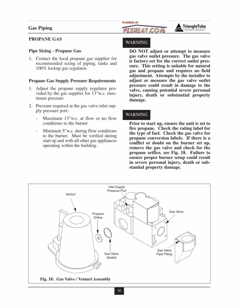
Prior to start up, ensure the unit is set tofire propane. Check the rating label forthe type of fuel. Check the gas valve forpropane conversion labels. If there is aconflict or doubt on the burner set up,remove the gas valve and check for thepropane orifice, see Fig. 18. Failure toensure proper burner setup could resultin severe personal injury, death or sub-stantial property damage.
WARNING
WARNING
Venturi
Inlet SupplyPressure Port
PropaneOrifice
Gas ValveGasket
Gas ValvePipe Fitting
Gas Valve
Fig. 18: Gas Valve / Venturi Assembly
31
Internal Wiring
SECTION VII - Internal Wiring
ELECTRICAL SHOCK HAZARD. Foryour safety, disconnect electrical powersupply to the unit before servicing ormaking any electrical connections toavoid possible electric shock hazard.Failure to do so can cause severe person-al injury or death.
Prior to servicing, label all wires prior todisconnection. Wiring errors can causeimproper and dangerous operation.Verify proper operation after servicing.
General Requirements
- Wiring must be N.E.C Class 1.
- If original wiring as supplied with the unitmust be replaced, use only Type T 90ºCwire or equivalent as a minimum.
- The PRESTIGE must be electricallygrounded as required by NationalElectrical Code ANSI/NFPA 70 - latest edi-tion and / or the Canadian Electrical CodePart 1, CSA C22.1, Electrical Code.
Wiring Tool Instructions
1. Locate the wiring tool on the PRESTIGEjust below the the MCBA control in a plas-tic bag.
2. Locate the terminal blocks on the PRES-TIGE below the MCBA control.
The 120V Terminals are located on theleft set of Terminal Blocks. The 24VTerminals are located on the right set ofterminal blocks.
3. Carefully pull down on the lower half ofthe terminal block to remove.
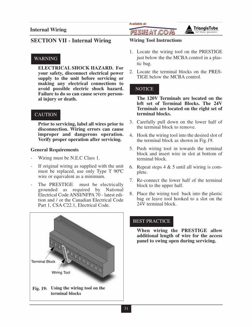
4. Hook the wiring tool into the desired slot ofthe terminal block as shown in Fig.19.
5. Push wiring tool in towards the terminalblock and insert wire in slot at bottom ofterminal block.
6. Repeat steps 4 & 5 until all wiring is com-plete.
7. Re-connect the lower half of the terminalblock to the upper half.
8. Place the wiring tool back into the plasticbag or leave tool hooked to a slot on the24V terminal block.
When wiring the PRESTIGE allowadditional length of wire for the accesspanel to swing open during servicing.
BEST PRACTICE
NOTICE
CAUTION
WARNING
Terminal Block
Wiring Tool
Fig. 19: Using the wiring tool on theterminal blocks
32
Internal Wiring
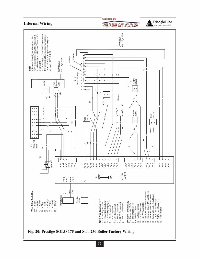
Fig. 20: Prestige SOLO 175 and Solo 250 Boiler Factory Wiring
33
External Wiring
SECTION VIII- External Wiring
Installation Compliance
All field wiring made during installation mustcomply with:
- National Electrical Code NFPA 70 andany other national, state, provincial orlocal codes or requirements.
- In Canada, CSA C22.1 CanadianElectrical Code Part 1, and any otherlocal codes.
ELECTRICAL SHOCK HAZARD.Before making any electrical connec-tions to the PRESTIGE, disconnect elec-trical power supply at the service panel.Failure to comply can cause severe per-sonal injury or death.
Line Voltage Connections
1. Connect 120 VAC power wire to the120V terminal strip on the wiring panelbelow the PRESTIGE control module, asshown in Fig. 20, page 32.
2. Route the incoming 120 VAC power wirethrough the provided openings in the bot-tom jacket panel.
3. The unit is provided with a service switchlocated on the front panel, check local coderequirements for compliance.
If local electrical codes or conditionsrequire an additional service switch, theinstaller must provide and install a fuseddisconnect or 15 amp (minimum) serviceswitch.
Domestic Hot Water Wiring
1. Connect the DHW circulator to the 120Vterminal strip on the wiring panel below thePRESTIGE control module, as shown inFig. 20, page 32.
2. Connect the DHW thermostat (aquastat) tothe 24V terminal strip on the wiring panellocated below the PRESTIGE control mod-ule as shown in Fig. 20, page 32.
Route all wiring through the provided open-ings, in the bottom jacket panel. Allow enoughwire for access panel to swing open during ser-vicing.
Thermostat Wiring
Isolate 120V wiring from 24V wiring toprevent any potential electrical “noise”.
1. Connect room thermostat or the end switch(isolated contact only) of a relay controlpanel to the 24V terminal strip on thewiring panel below the PRESTIGE controlmodule, as shown in Fig. 20, page 32.
2. For proper operation install the room ther-mostat on an inside wall away from influ-ences of heat and cold, i.e. water pipes,areas of draft, lighting fixtures and fire-places.
3. Set the thermostat anticipator (if applica-ble) as follows:
- Set for 0.2 amps when wired directly tothe PRESTIGE.
- Set to match the total electrical powerrequirements of the connected deviceswhen wired to zone relays or otherdevices. Refer to the relay manufactur-ers’ specifications and the thermostatinstructions for additional informationon the anticipator setting.
NOTICE
NOTICE
WARNING
34
External Wiring
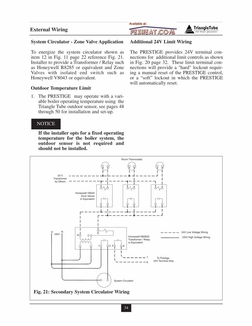
System Circulator - Zone Valve Application
To energize the system circulator shown asitem 12 in Fig. 11 page 22 reference Fig. 21.Installer to provide a Transformer / Relay suchas Honeywell R8285 or equivalent and ZoneValves with isolated end switch such asHoneywell V8043 or equivalent.
Outdoor Temperature Limit
1. The PRESTIGE may operate with a vari-able boiler operating temperature using theTriangle Tube outdoor sensor, see pages 48through 50 for installation and set-up.
If the installer opts for a fixed operatingtemperature for the boiler system, theoutdoor sensor is not required andshould not be installed.
Additional 24V Limit Wiring
The PRESTIGE provides 24V terminal con-nections for additional limit controls as shownin Fig. 20 page 32. These limit terminal con-nections will provide a "hard" lockout requir-ing a manual reset of the PRESTIGE control,or a “soft” lockout in which the PRESTIGEwill automatically reset.
NOTICE
24 VTransformerby Others
Honeywell V8043Zone Valves
or Equivalent
Honeywell R8285DTransformer / Relayor Equivalent
24V Terminal Strip
System Circulator
24V Low Voltage Wiring
120V High Voltage Wiring
Room Thermostats
H N120V R C
G
1 3 4 6
7
8
To Prestige
Fig. 21: Secondary System Circulator Wiring
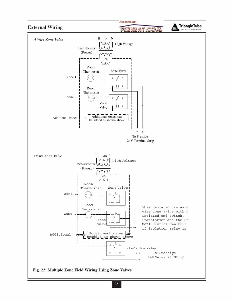
35
External Wiring
H N
High Voltage
120V.A.C.
24V.A.C.
RoomThermostat
RoomThermostat
Zone 1
Zone 2
Additional zones Additional zones maybe added as shown above
To Prestige 24V Terminal Strip
Transformer(Power)
ZoneValve
Zone Valve
7 8
To Prestige 24V Terminal Strip
H N
High Voltage
120V.A.C.
24V.A.C.
RoomThermostat
RoomThermostat
Zone 1
Zone 2
Additional zones Additional zones maybeadded as shown above
Transformer(Power)
ZoneValve
Zone Valve
*Isolation relay
7
8
*Use isolation relay owire zone valve with nisolated end switch. Transformer and the PrMCBA control can burn if isolation relay is
4 Wire Zone Valve
3 Wire Zone Valve
Fig. 22: Multiple Zone Field Wiring Using Zone Valves
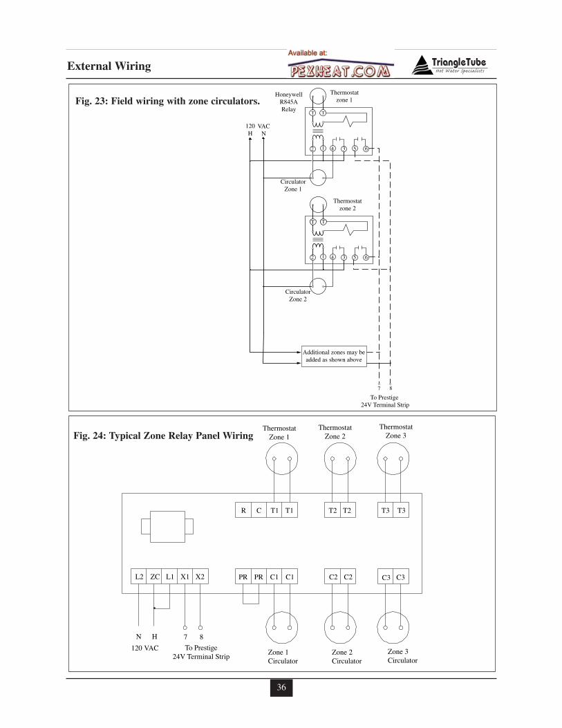
36
External Wiring
T T
To Prestige 24V Terminal Strip
CirculatorZone 1
Thermostatzone 1
HoneywellR845ARelay
120H
VACN
CirculatorZone 2
Thermostatzone 2
Additional zones may beadded as shown above
7 8
62 1 4 3 5
62 1 4 3 5
T T
T T
Fig. 23: Field wiring with zone circulators.
ThermostatZone 1
Zone 1Circulator
120 VAC
N
To Prestige24V Terminal Strip
Zone 2Circulator
Zone 3Circulator
ThermostatZone 2
ThermostatZone 3
R C T1 T1 T2T2 T3 T3
C3C3C2C2C1C1PRPRX2X1L1L2 ZC
H 7 8
Fig. 24: Typical Zone Relay Panel Wiring
37
Start-Up Preparation
SECTION IX - Start-Up Preparation
Check Boiler System Water Chemistry
Do not use petroleum-base cleaning orsealing compounds in the boiler system.Damage to seals and gaskets in the sys-tem components could occur, resulting insubstantial property damage.
System water including additives must bepractically non-toxic, having a toxicityrating or Class of 1, as listed in ClinicalToxicology of Commercial Products.
Water pH Level 6.0 to 8.0
Maintain the boiler water pH between 6.0 and8.0. Check using litmus paper or contact a watertreatment company for a chemical analysis.
If the pH does not meet this requirement, donot operate the PRESTIGE or leave the unitfilled until the condition is corrected.
Water Hardness Less Than 7 Grains
For areas with unusually hard water (hardnessabove 7 grains) consult a water treatmentcompany.
Chlorinated Water
Do not use the PRESTIGE to heat a swimmingpool or spa directly.
Maintain the chlorine level of the water at lev-els considered safe for drinking.
Flush Boiler and Domestic System toRemove Sediment
The installer must flush the boiler system toremove any sediment to allow proper operationof the PRESTIGE .
Flush the systems until the water runs cleanand is free of sediment.
For boiler zoned systems, each zone should beflushed through a purge valve. Purge valvesand isolation valves should be installed on eachzone to allow proper flushing of the system.
Check and Test Antifreeze
For boiler systems containing antifreeze solu-tions, follow the antifreeze manufacturer’sinstructions in verifying the inhibitor level andto ensure the fluid characteristics are withinspecification requirements.
Due to the degradation of inhibitors over time,antifreeze fluids must be periodically replaced.Refer to the manufacturer of the antifreeze foradditional instructions.
System water including additives must bepractically non-toxic, having a toxicityrating or Class of 1, as listed in ClinicalToxicology of Commercial Products.
NOTICE
NOTICE
WARNING
38
Start-Up Preparation
Use of Antifreeze in the Boiler System
NEVER use automotive or ethylene gly-col antifreeze or undiluted antifreeze inthe primary system as freeze protection.This can cause severe personal injury,death or substantial property damage ifignored.
Determine the antifreeze fluid quantity usingthe system water content volume and followingthe antifreeze manufacturer instructions.
The water volume of the PRESTIGE is approx-imately 4 to 5 gallons [ 15 to 19 L]. Rememberto include the volume of the expansion tank.
Check with local codes requirements for theinstallation of backflow preventers or actualdisconnect from the boiler’s cold water fill ormake up water supply line.
Massachusetts Code requires the installa-tion of a backflow preventer if antifreezeis used.
Ensure the concentration of antifreeze to waterdoes not exceed a 50/50 ratio.
System water, including additives, mustbe practically non-toxic, having a toxicityrating or Class of 1, as listed in ClinicalToxicology of Commercial Products.
Filling the Boiler System
1. Close the boiler drain valve located on thebottom of the unit and any manual or auto-matic air vent in the system.
2. Open all system isolation valves.
3. Fill the boiler system to correct systempressure. Correct pressure will vary witheach application.
Typical residential system fill pressure is12 psi. System pressure will increasewhen system temperature increases.Operating pressure of the system shouldnever exceed 25 psi.
4. Purge air and sediment in each zone of theboiler system through the purge valve.Open air vents to allow air to be purged inthe zones.
5. Once the system is completely filled andpurged of all air and sediment, check thesystem pressure and check/repair anyleaks.
Unrepaired system leaks will cause con-tinual makeup water to be added to theboiler. Continual makeup water couldcause mineral buildup within the heatexchanger, reducing the heat transfer,causing possible heat buildup and even-tual heat exchanger failure.
Check Low Water Cut-Off Device
- The PRESTIGE is provided with a factoryinstalled LWCO device that measures sys-tem pressure of more than 10 psi.
- Remove the front jacket panel and check forcontinuity across the low water cut-offdevice wire terminals. The contacts shouldbe closed when system pressure is greaterthan 10 psi. See item 5, on Fig. 27 page 62.
WARNING
NOTICE
NOTICE
NOTICE
WARNING
39
Start-Up Preparation
Check For Gas Leaks
Prior to start-up and during initial opera-tion, smell near the floor and around theunit for gas odorant or any unusual odor.Do not proceed with the start-up if thereis any indication of a gas leak. Any leaksfound must be repaired immediately.
Propane installations only - The propanesupplier mixes an odorant with thepropane to make its presence detectable.In some cases the odorant can fade andthe gas may no longer have an odor.
Prior to start-up of the unit and periodi-cally after start-up have the propanesupplier check and verify the odorantlevel.
Check Thermostat Circuit
- Disconnect the external thermostat wiresfrom the 24V terminal strip on the wiringpanel.
- Connect a voltmeter across the wire ends ofthe external thermostat wiring.
- Close each thermostat, zone valve andrelay in the external circuit one zone at atime and check the voltage reading acrossthe wire ends.
- There should NEVER be voltage measuredat the wire ends.
- If voltage is measured at the panel under anycondition, check and correct the externalwiring.
In systems using 3-wire zone valves,backfeed of voltage to the unit is a com-mon problem. Use an isolation relay toprevent voltage from the external circuitentering the PRESTIGE control panel.
- Reconnect the external thermostatwires to the 24V terminal strip on thewiring panel.
Inspection of Condensate System
1. Inspect and ensure the condensate drainsystem is properly installed as described onpage 26 and shown in Fig. 16 on page 27.
2. Remove the plug from the Condensate Trapassembly and fill the trap with fresh water.
The condensate trap assembly must befilled with water when the PRESTIGE isin operation. The condensate trapassembly prevents flue gas emissionsfrom entering the condensate line.Failure to ensure trap is filled with watercould result in severe personal injury ordeath.
3. Re-Install plug in condensate drain assem-bly.
NOTICE
NOTICE
WARNING
WARNING
40
Start-Up Procedures
SECTION X - Start-Up Procedures
Final Checks Before Start-up
� Read page 43 regarding the operation of thePRESTIGE control.
� Verify the PRESTIGE and the boiler sys-tem is full of water and all system compo-nents are correctly set for operation, includ-ing the minimum flow rate through theboiler, see page 68.
� Verify Start-up Preparation items outlined onpages 37 thru 39 have been completed.
� Verify all electrical connections are correctand securely fastened.
� Inspect vent piping and combustion air inletpiping for signs of deterioration from corro-sion, physical damage or sagging. Verifycombustion air piping and vent piping areintact and correctly installed and supported.Reference the PRESTIGE vent supplement.
� Verify burner configuration - Propane only.
- Check for proper labeling on the gasvalve, combustion air inlet and the rat-ing label for propane configuration.
- If there is doubt on the burner configu-ration, remove the gas valve and checkfor proper propane orifice size 0.221”(SOLO 175) or 0.250” (SOLO 250).Refer to Fig. 18, page 30 for location ofthe propane orifice.
� Ensure the vent Condensate Trap Assemblyis filled with water.
PRESTIGE Start-up
1. Turn the ON-OFF switch located on thefront control panel to the OFF position.Turn the electrical supply or any serviceswitch to the unit in the ON position.
2. Read and follow the Operating Instructionsoutlined on page 42.
If PRESTIGE Does Not Start Correctly
1. Verify CH (parameter 2) and DHW (para-meter 3) systems are turned ON or set to“01”. Read the Boiler Display Standby andParameter Section of the manual startingon page 45 for more information.
2. Check for loose electrical connections,blown fuse (external or internal to theMCBA Control) or open service switch.
3. Check continuity across the L.W.C.Odevice for a closed circuit. See item 5 onFig. 27, page 62.
4. Is the external limit control (if applicable)open? Ensure the external limit is reset tothe closed position.
5. Is the gas supply valve(s) open at the unitand meter?
6. Is incoming gas supply pressure at the unitmore than 5”w.c. and less than 13” w.c. fornatural or propane with all gas appliancesoperating?
7. Are the heating thermostats set below roomtemperature?
If none of these conditions correct the problem,refer to the PRESTIGE Trouble-ShootingGuide or contact Triangle Tube Tech Service.
Check the PRESTIGE and System
� Check Boiler Piping.
Check Boiler system piping and com-ponents for leaks. If found, shut downthe unit and repair immediately.
Purge any remaining air from the systempiping. Air in the system piping willinterfere with circulation creating heatdistribution problems and system noise.
� Check Vent Piping and Combustion AirPiping.
Check for gas-tight seal at every con-nection and seam of the venting andcombustion air inlet piping.
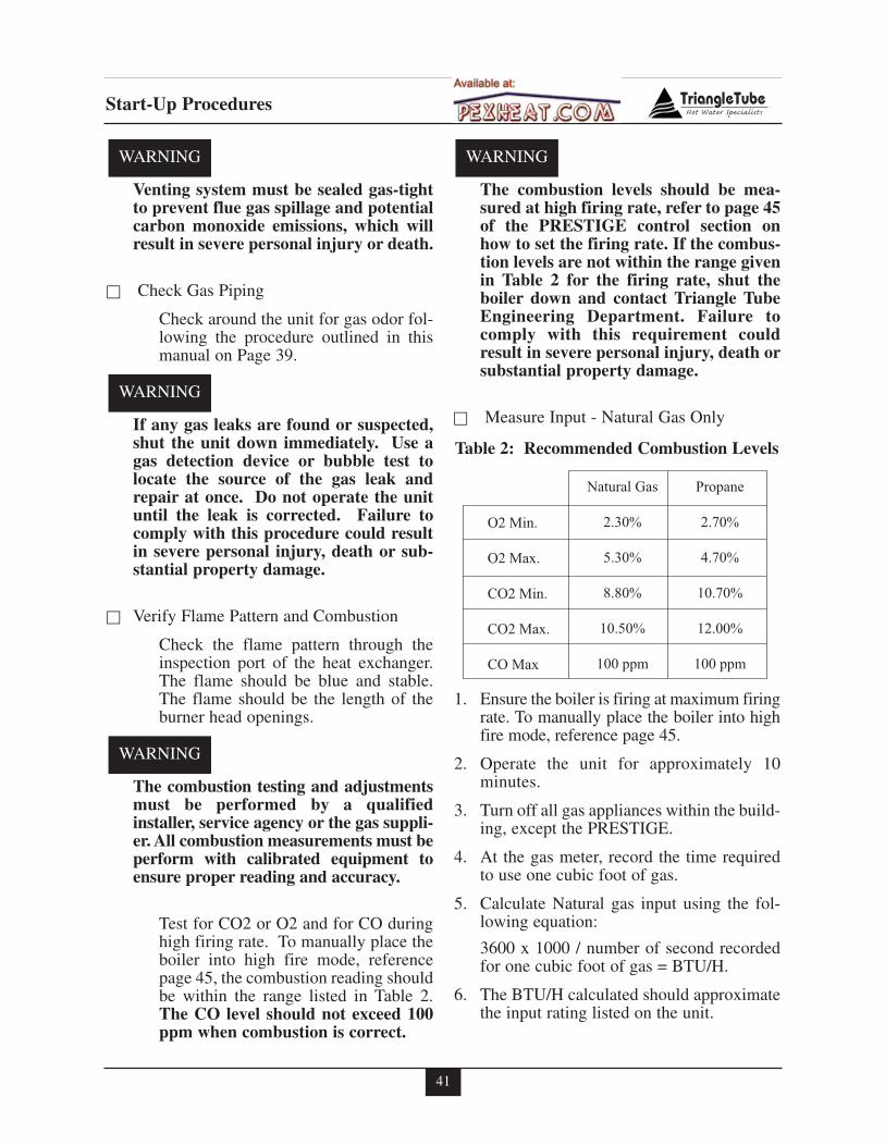
41
Start-Up Procedures
Venting system must be sealed gas-tightto prevent flue gas spillage and potentialcarbon monoxide emissions, which willresult in severe personal injury or death.
� Check Gas Piping
Check around the unit for gas odor fol-lowing the procedure outlined in thismanual on Page 39.
If any gas leaks are found or suspected,shut the unit down immediately. Use agas detection device or bubble test tolocate the source of the gas leak andrepair at once. Do not operate the unituntil the leak is corrected. Failure tocomply with this procedure could resultin severe personal injury, death or sub-stantial property damage.
� Verify Flame Pattern and Combustion
Check the flame pattern through theinspection port of the heat exchanger.The flame should be blue and stable.The flame should be the length of theburner head openings.
The combustion testing and adjustmentsmust be performed by a qualifiedinstaller, service agency or the gas suppli-er. All combustion measurements must beperform with calibrated equipment toensure proper reading and accuracy.
Test for CO2 or O2 and for CO duringhigh firing rate. To manually place theboiler into high fire mode, referencepage 45, the combustion reading shouldbe within the range listed in Table 2.The CO level should not exceed 100ppm when combustion is correct.
The combustion levels should be mea-sured at high firing rate, refer to page 45of the PRESTIGE control section onhow to set the firing rate. If the combus-tion levels are not within the range givenin Table 2 for the firing rate, shut theboiler down and contact Triangle TubeEngineering Department. Failure tocomply with this requirement couldresult in severe personal injury, death orsubstantial property damage.
� Measure Input - Natural Gas Only
1. Ensure the boiler is firing at maximum firingrate. To manually place the boiler into highfire mode, reference page 45.
2. Operate the unit for approximately 10minutes.
3. Turn off all gas appliances within the build-ing, except the PRESTIGE.
4. At the gas meter, record the time requiredto use one cubic foot of gas.
5. Calculate Natural gas input using the fol-lowing equation:
3600 x 1000 / number of second recordedfor one cubic foot of gas = BTU/H.
6. The BTU/H calculated should approximatethe input rating listed on the unit.
WARNING
WARNING
WARNING
WARNING
O2 Min.
O2 Max.
CO2 Min.
CO2 Max.
CO Max
Natural Gas
2.30%
5.30%
8.80%
10.50%
100 ppm
Propane
2.70%
4.70%
10.70%
12.00%
100 ppm
Table 2: Recommended Combustion Levels
42
Start-Up Procedures
WARNING
FOR YOUR SAFETY READ BEFORE LIGHTING
OPERATING INSTRUCTIONS
TO TURN OFF GAS TO APPLIANCE
1. STOP! Read the safety information above. Thisappliance is equipped with an ignition devicewhich automatically lights the burner. DO NOTtry to light the burner by hand.
2. Set room thermostat(s) to lowest setting. Turn theexternal manual gas valve handle clockwise
“CLOSE” (valve handle shall be per-pendicular to gas piping).
3. Turn the service switch on the PRESTIGE con-trol panel OFF.
4. Remove the front jacket panel on the unit.
5. Turn the external manual gas valve handlecounter clockwise to “OPEN” gas sup-ply (valve handle shall be parallel to gas piping).
6. Wait five (5) minutes to clear out any gas. If youthen smell gas in the jacket enclosure or aroundthe unit, STOP! Follow “B” in the safety infor-mation above. If you don’t smell gas, go to thenext step.
7. Turn the service switch on the PRESTIGE con-trol panel “ON”.
8. Set room thermostat(s) to desired setting(s).
9. The PRESTIGE control panel display will showa sequence of numbers (0,1,2,3,4,etc.) as the leftdigit. Sequence digit 3 or 4 indicates the boiler isfiring. Sequence digit 0 means there is no call forheat (all external thermostats are satisfied).
10. If the unit will not operate with a call for heat and thesystem piping is not hot, follow the instructions “ToTurn Off Gas to Appliance”, below and call yourservice technician or gas supplier.
11. Replace the front jacket panel. Make sure the panel isseated firmly in place and all mounting screws aretightened.
If you do not follow these instructions exactly, a fire or explosionmay result causing property damage, personal injury or loss of life.
1. Set the room thermostat to lowest setting.
2. Turn the service switch on the PRESTIGE con-trol panel to “OFF”
3. Turn the external manual gas valve handle clock-wise to “CLOSE”.
A. This appliance does not have a pilot. It isequipped with an ignition device which automat-ically lights the burner. DO NOT try to light theburner by hand.
B. BEFORE OPERATING, smell all around theappliance area for gas. Be sure to smell next tothe floor because some gas is heavier than air andwill settle on the floor.
WHAT TO DO IF YOU SMELL GAS• Do not try to light any appliance.
• Do not touch any electric switch; do not useany phone in your building
• Immediately call your gas supplier from aneighbor’s phone. Follow the gas supplier’sinstructions.
• If you cannot reach your gas supplier, call thefire department.
C. Use only your hand to turn the external manual gasvalve. Never use tools. If the valve will not turn byhand, don’t try to repair it; call a qualified servicetechnician. Force or attempted repair may result ina fire or explosion.
D. Do not use this appliance if any part has beenunder water. Immediately call a qualified servicetechnician to inspect the appliance and to replaceany part of the control system and any gas controlwhich has been under water.
43
Start-Up Procedures
Set Boiler CH Target Temperature
1. Press the MODE button until the displayshows PARA. This is the parameter modeof the control.
2. Press the STEP button until the first digiton the display shows "4". The last threedigits on the display shows the outlet watertemperature setting (high limit).
3. Press the "+" or "-" button to change thesetting of the outlet temperature (highlimit).
If an outdoor sensor is used, then the set-ting of the Boiler CH Target temperatureis the target temperature when the out-door temperature is at or below 0ºF.When the outdoor temperature is higherthan 0ºF the PRESTIGE control will cal-culate the target temperature between theminimum and maximum temperaturesettings.
4. Press the "STORE" button to save the setting.
Operation Verification - Space Heating
Digits and characters shown as [00000000],in the following outline, represent thecontrol panel display. The last three dig-its on the display is the measured boilerwater temperature and may differ fromwhat is shown in the manual.
1. Disconnect the DHW (Domestic HotWater) thermostat wiring from the PRES-TIGE or turn down DHW tank aquastat (ifused) to ensure the boiler does not receivea DHW call for heat.
2. Set the room thermostat to the lowest setting.
3. Turn off power to the boiler, wait a fewseconds and turn on power to the boiler.
4. The following displays should occur:
[A140] Self check on power up
[0140] No call for heat
5. Initiate a call for heat by raising the setpoint of the room thermostat to the highestsetting. The following display shouldoccur.
[1140] This is the prepurge cycle. Theboiler blower and the CH (Central Heating)circulator become energized. The blowerhas a 10 second prepurge cycle.
[2140] This is the ignition cycle. The con-trol module will energize and open the gasvalve and begin the spark for ignition.
- If the burner flame proves the burnerwill continue to fire at the ignition fanspeed for approximately 10 seconds tostabilize the flame.
- If the burner flame is not proven thecontrol module will repeat the ignitionsequence. If the flame is not provenafter five attempts the control will lock-out and the display will show [E-02]
- To verify flame failure lockout, closethe manual shut off valve on the gassupply piping to the boiler and repeatignition sequence. When verification iscompleted, ensure the manual shut offvalve is returned to the open position.
[3140] This is the normal operation cycle.After the flame is proven and stabilizedthe burner will fire at low input forapproximately 1 minute. After this timeperiod, the control module will begin tomodulate the burner firing rate based onactual boiler outlet temperature and the setpoint temperature.
NOTICE
NOTICE
44
Start-Up Procedures
6. Allow the boiler to operate and allow theboiler outlet temperature to reach the setpoint temperature.
[6180] This begins the burner shutdownand post purge cycle. The CH circulatorwill continue to run until the room thermo-stat is satisfied.
7. Lower the room thermostat set point belowthe room temperature to end the call forheat.
[1180] This begins a post purge cycle.When the room thermostat is satisfied, theboiler will shutdown. The control modulewill close the gas valve and the blower willcontinue for 30 seconds for a post purgecycle before shutting down. If another callfor heat is initiated, the boiler will remainoff for an additional 30 seconds beforestarting a new ignition sequence.
[7180] The CH circulator will continuefor a 1 minute post pump cycle. The boileris in standby MODE waiting for a call forheat.
8. Verify the operation of the boiler by repeat-ing the operational sequence several times.
9. Return the room thermostat to a desired set-ting. Reconnect the DHW wiring or returnthe DHW aquastat to desired setting, plac-ing the DHW system into operation.
Operation Verification - Domestic HotWater (if applicable)
1. As outlined in the verification for spaceheating, repeat STEPS 2 through 4.
2. Raise the DHW aquastat setting to initiate acall for heat. As in the space heating opera-tion the display should show:
[1180] The prepurge cycle. The boilerblower and DHW circulator become ener-gized and the 10 second pre-purge cyclebegins.
[2180] The boiler will begin the ignitionsequence. The same sequence of establish-ing flame, trail for ignition and attempts forignition as described in the space heatingapplies for domestic water heater.
[4180] This indicates normal operationfor DHW. The burner will begin modulat-ing its input based on the length of demandby the DHW aquastat. The burner will notgo into the low input rate for the 1 minuteflame stabilization period that occurs in CHmode.
3. Lower the DHW aquastat to satisfy the callfor heat.
[1180] The post purge cycle begins. Thecontrol module closes the gas valve and theblower continues for a 30 second postpurge.
[8180] The DHW will continue for a 30second post pump cycle. If another DHWcall for heat is initiated the boiler ignitionsequence will begin immediately.
[0180] Boiler is in standby MODE wait-ing for a CH or DHW call for heat.
4. Verify the DHW operation of the boiler byrepeating the outline operation sequenceseveral times.
5. Return the DHW aquastat and room ther-mostat to the desired setting.
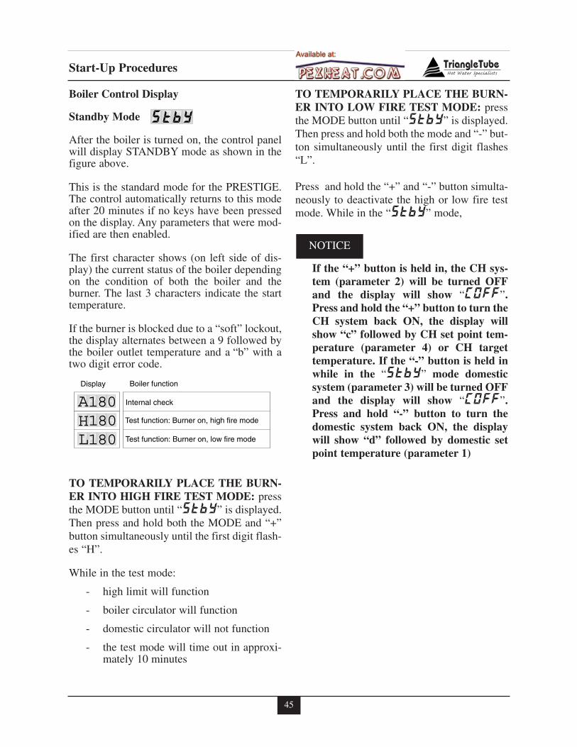
45
Start-Up Procedures
Boiler Control Display
Standby Mode
After the boiler is turned on, the control panelwill display STANDBY mode as shown in thefigure above.
This is the standard mode for the PRESTIGE.The control automatically returns to this modeafter 20 minutes if no keys have been pressedon the display. Any parameters that were mod-ified are then enabled.
The first character shows (on left side of dis-play) the current status of the boiler dependingon the condition of both the boiler and theburner. The last 3 characters indicate the starttemperature.
If the burner is blocked due to a “soft” lockout,the display alternates between a 9 followed bythe boiler outlet temperature and a “b” with atwo digit error code.
TO TEMPORARILY PLACE THE BURN-ER INTO HIGH FIRE TEST MODE: pressthe MODE button until “StbY” is displayed.Then press and hold both the MODE and “+”button simultaneously until the first digit flash-es “H”.
While in the test mode:
- high limit will function
- boiler circulator will function
- domestic circulator will not function
- the test mode will time out in approxi-mately 10 minutes
TO TEMPORARILY PLACE THE BURN-ER INTO LOW FIRE TEST MODE: pressthe MODE button until “StbY” is displayed.Then press and hold both the mode and “-” but-ton simultaneously until the first digit flashes“L”.
Press and hold the “+” and “-” button simulta-neously to deactivate the high or low fire testmode. While in the “StbY” mode,
If the “+” button is held in, the CH sys-tem (parameter 2) will be turned OFFand the display will show “COFF”.Press and hold the “+” button to turn theCH system back ON, the display willshow “c” followed by CH set point tem-perature (parameter 4) or CH targettemperature. If the “-” button is held inwhile in the “StbY” mode domesticsystem (parameter 3) will be turned OFFand the display will show “COFF”.Press and hold “-” button to turn thedomestic system back ON, the displaywill show “d” followed by domestic setpoint temperature (parameter 1)
NOTICE
StbY
Internal check
Test function: Burner on, high fire mode
Test function: Burner on, low fire mode
A180180180HL
Display Boiler function
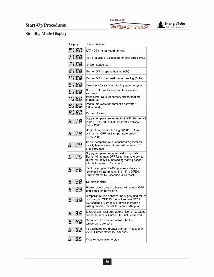
46
Start-Up Procedures
STANDBY, no demand for heat
Fan prepurge (10 seconds) or post purge cycle
Ignition sequence
Burner ON for space heating (CH)
Burner ON for domestic water heating (DHW)
Pre-check for air flow prior to prepurge cycle
Burner OFF due to reaching temperature set point
Post pump cycle for domestic hot water (30 seconds)
Post pump cycle for primary space heating (1 minute)
Burner blocked:
Supply temperature too high (203 F) .Burner willremain OFF until outlet temperature dropsbelow 200 F
Return temperature too high (203 F). Burner will remain OFF until temperature drops below 200 F
Return temperature is measured higher than supply temperature. Burner will remain OFFuntil corrected.
Supply temperature increased too quickly. Burner will remain OFF for a 10 minute period. Burner will recycle, increasing waiting period 1 minute for a max. 15 minutes
Factory supplied LWCO pressure device or external limit (terminals 15 & 16) is OPEN. Burner off for 150 seconds, auto reset.
01180180180180180180180180180180
2345678918b
19b
24b
25b
26b
2
Display Boiler function
No blower signal
Blower signal present, Burner will remain OFF until condition terminates
Temperature rise between the supply and returnis more than 72 F. Burner will remain OFF for 150 seconds. Burner will recycle increasing wating period 1 minute for a max. 20 cycle.
Short circuit measured across flue temperaturesensor terminals. Burner OFF until corrected.
Open circuit measured across the flue temperature sensors.
Flue temperature greater than 241 F less than250 F. Burner off for 150 seconds
Wait for the blower to start
8b229b
30b
35b40b52b65b
Standby Mode Display
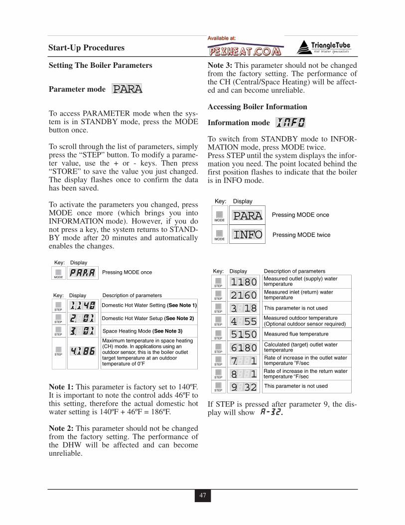
47
Start-Up Procedures
Setting The Boiler Parameters
Parameter mode
To access PARAMETER mode when the sys-tem is in STANDBY mode, press the MODEbutton once.
To scroll through the list of parameters, simplypress the “STEP” button. To modify a parame-ter value, use the + or - keys. Then press“STORE” to save the value you just changed.The display flashes once to confirm the datahas been saved.
To activate the parameters you changed, pressMODE once more (which brings you intoINFORMATION mode). However, if you donot press a key, the system returns to STAND-BY mode after 20 minutes and automaticallyenables the changes.
Note 1: This parameter is factory set to 140ºF.It is important to note the control adds 46ºF tothis setting, therefore the actual domestic hotwater setting is 140ºF + 46ºF = 186ºF.
Note 2: This parameter should not be changedfrom the factory setting. The performance ofthe DHW will be affected and can becomeunreliable.
Note 3: This parameter should not be changedfrom the factory setting. The performance ofthe CH (Central/Space Heating) will be affect-ed and can become unreliable.
Accessing Boiler Information
Information mode
To switch from STANDBY mode to INFOR-MATION mode, press MODE twice.Press STEP until the system displays the infor-mation you need. The point located behind thefirst position flashes to indicate that the boileris in INFO mode.
If STEP is pressed after parameter 9, the dis-play will show A-32.
NFOI
ARAP
ARAPMODE
NFOIMODE
Key: Display
Pressing MODE once
Pressing MODE twice
Measured outlet (supply) watertemperature
Measured inlet (return) water temperature
This parameter is not used
Measured outdoor temperature(Optional outdoor sensor required)
1.21180601855
34
STEP
STEP
STEP
STEP
Key: Display Description of parameters
Measured flue temperature
Rate of increase in the outlet watertemperature F/sec
Rate of increase in the return watertemperature F/sec
This parameter is not used
6.71801132
89
.
.
.
.
.
STEP
Calculated (target) outlet water temperature
5.150STEP
STEP
STEP
STEP
Domestic Hot Water Setting (See Note 1)
Domestic Hot Water Setup (See Note 2)
Space Heating Mode (See Note 3)
Maximum temperature in space heating(CH) mode. In applications using an outdoor sensor, this is the boiler outlet target temperature at an outdoor temperature of 0 F
1.21400101
81 6
ARA
3
4
P
.
.
.
.
MODE
STEP
STEP
STEP
STEP
Key: Display
Key: Display
Description of parameters
Pressing MODE once
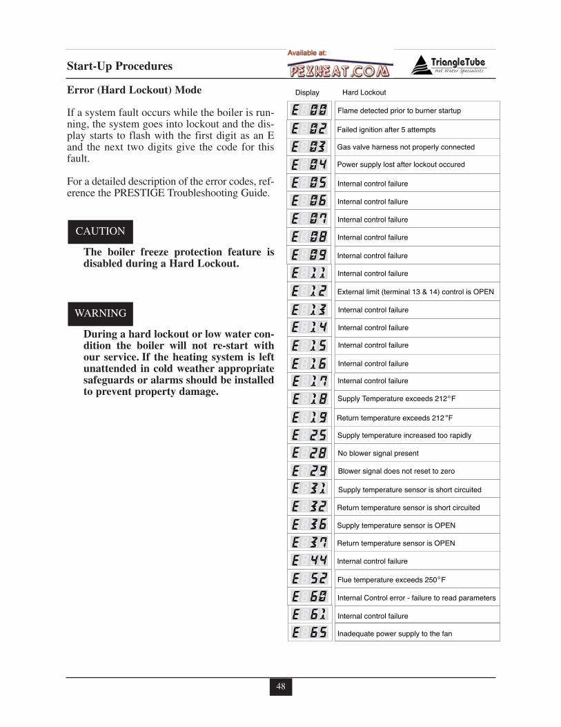
48
Start-Up Procedures
Error (Hard Lockout) Mode
If a system fault occurs while the boiler is run-ning, the system goes into lockout and the dis-play starts to flash with the first digit as an Eand the next two digits give the code for thisfault.
For a detailed description of the error codes, ref-erence the PRESTIGE Troubleshooting Guide.
The boiler freeze protection feature isdisabled during a Hard Lockout.
During a hard lockout or low water con-dition the boiler will not re-start withour service. If the heating system is leftunattended in cold weather appropriatesafeguards or alarms should be installedto prevent property damage.
WARNING
CAUTION
Gas valve harness not properly connected
Failed ignition after 5 attempts
Power supply lost after lockout occured
Internal control failure
Internal control failure
EE020304
0809
EE
E
Display Hard Lockout
Internal control failure05E Internal control failure06E Internal control failure07E
Flame detected prior to burner startupE 00
Internal control failure
External limit (terminal 13 & 14) control is OPEN
Blower signal does not reset to zero
No blower signal present
Supply temperature sensor is short circuited
1112
1516
2928
E
EE
EE
E Flue temperature exceeds 250 F52E Internal Control error - failure to read parameters
61
E
Return temperature sensor is short circuited
Supply temperature sensor is OPEN
Return temperature sensor is OPEN
Internal control failure
Internal control failure
Inadequate power supply to the fan
EE3132363744
60
65
EEE
EE
Return temperature exceeds 212 F
Supply temperature increased too rapidly
Internal control failure
Internal control failure
Internal control failure
Internal control failure
Internal control failure17
1925
13
E
EE
E
Supply Temperature exceeds 212 F18E
E 14
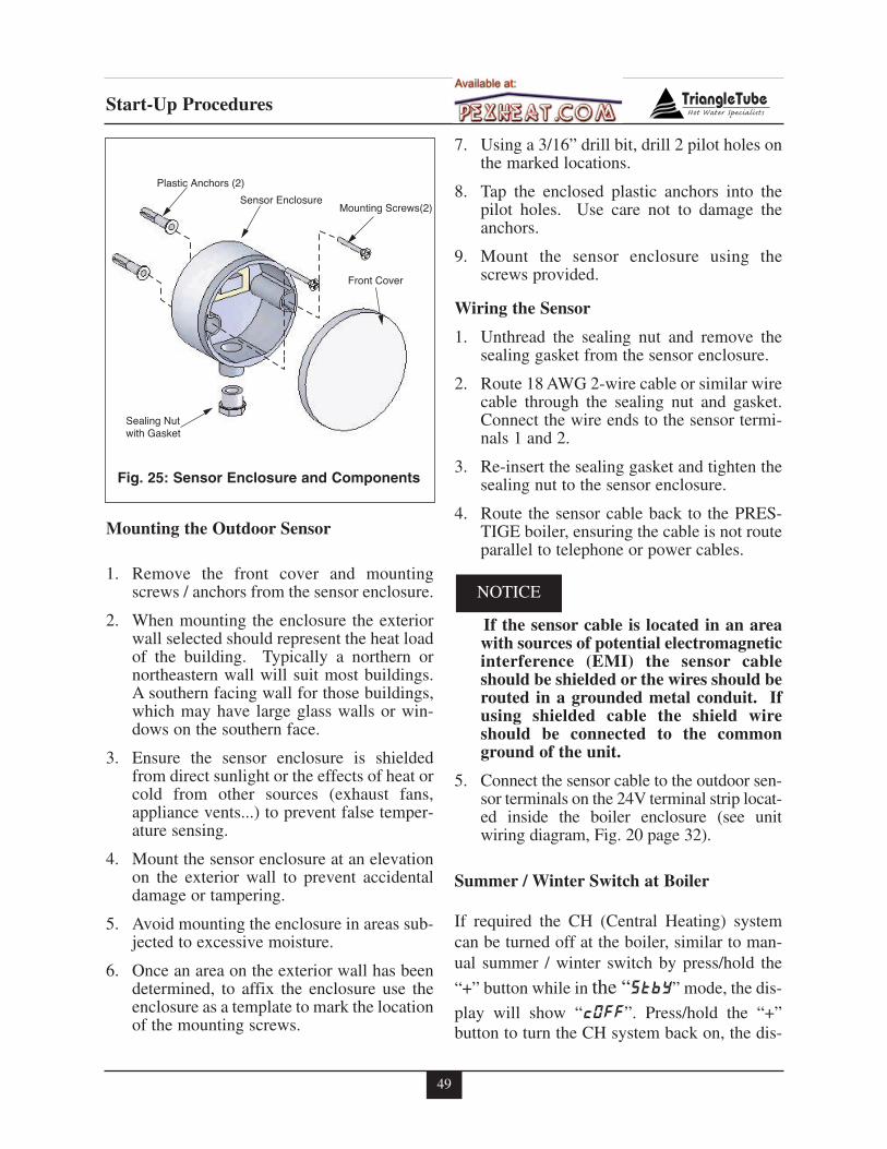
49
Start-Up Procedures
Mounting the Outdoor Sensor
1. Remove the front cover and mountingscrews / anchors from the sensor enclosure.
2. When mounting the enclosure the exteriorwall selected should represent the heat loadof the building. Typically a northern ornortheastern wall will suit most buildings.A southern facing wall for those buildings,which may have large glass walls or win-dows on the southern face.
3. Ensure the sensor enclosure is shieldedfrom direct sunlight or the effects of heat orcold from other sources (exhaust fans,appliance vents...) to prevent false temper-ature sensing.
4. Mount the sensor enclosure at an elevationon the exterior wall to prevent accidentaldamage or tampering.
5. Avoid mounting the enclosure in areas sub-jected to excessive moisture.
6. Once an area on the exterior wall has beendetermined, to affix the enclosure use theenclosure as a template to mark the locationof the mounting screws.
7. Using a 3/16” drill bit, drill 2 pilot holes onthe marked locations.
8. Tap the enclosed plastic anchors into thepilot holes. Use care not to damage theanchors.
9. Mount the sensor enclosure using thescrews provided.
Wiring the Sensor
1. Unthread the sealing nut and remove thesealing gasket from the sensor enclosure.
2. Route 18 AWG 2-wire cable or similar wirecable through the sealing nut and gasket.Connect the wire ends to the sensor termi-nals 1 and 2.
3. Re-insert the sealing gasket and tighten thesealing nut to the sensor enclosure.
4. Route the sensor cable back to the PRES-TIGE boiler, ensuring the cable is not routeparallel to telephone or power cables.
If the sensor cable is located in an areawith sources of potential electromagneticinterference (EMI) the sensor cableshould be shielded or the wires should berouted in a grounded metal conduit. Ifusing shielded cable the shield wireshould be connected to the commonground of the unit.
5. Connect the sensor cable to the outdoor sen-sor terminals on the 24V terminal strip locat-ed inside the boiler enclosure (see unitwiring diagram, Fig. 20 page 32).
Summer / Winter Switch at Boiler
If required the CH (Central Heating) systemcan be turned off at the boiler, similar to man-ual summer / winter switch by press/hold the
“+” button while in the “StbY” mode, the dis-
play will show “cOFF”. Press/hold the “+”button to turn the CH system back on, the dis-
NOTICE
Plastic Anchors (2)
Sensor EnclosureMounting Screws(2)
Front Cover
Sealing Nutwith Gasket
Fig. 25: Sensor Enclosure and Components
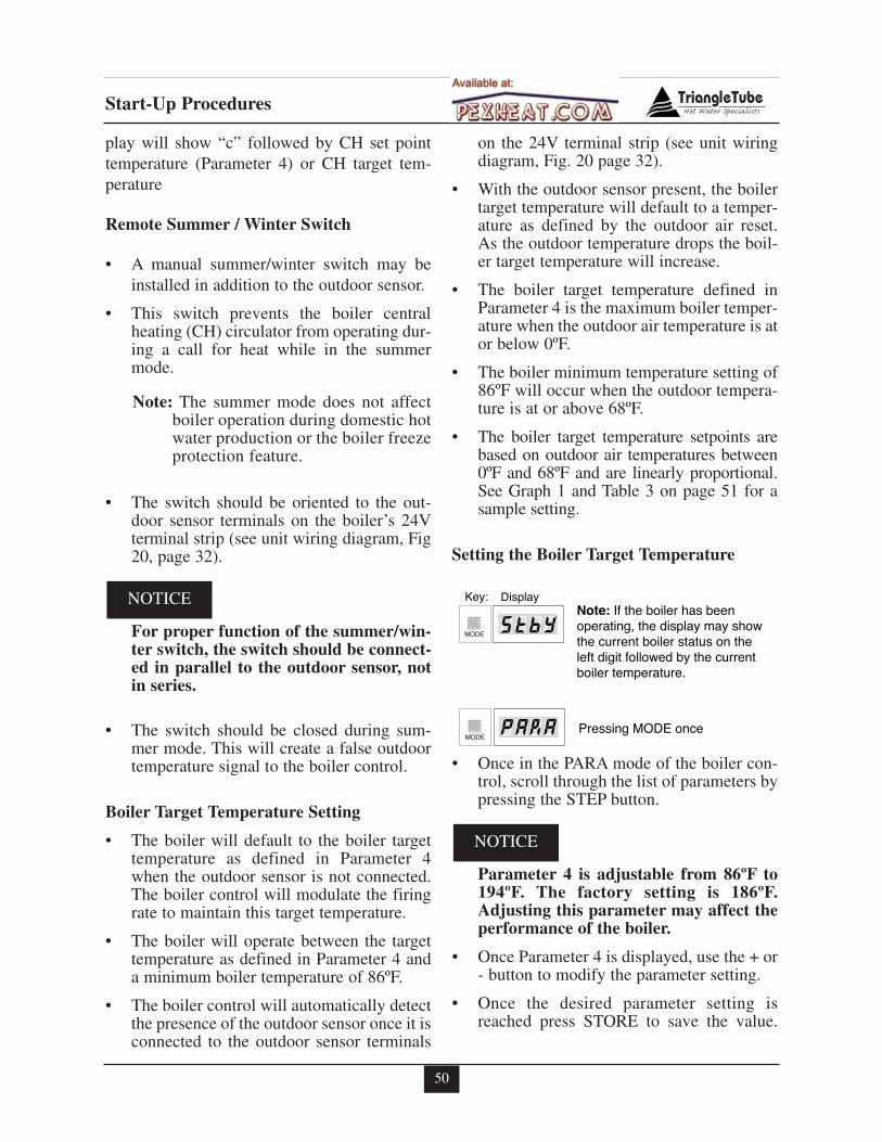
50
Start-Up Procedures
play will show “c” followed by CH set pointtemperature (Parameter 4) or CH target tem-perature
Remote Summer / Winter Switch
• A manual summer/winter switch may beinstalled in addition to the outdoor sensor.
• This switch prevents the boiler centralheating (CH) circulator from operating dur-ing a call for heat while in the summermode.
Note: The summer mode does not affectboiler operation during domestic hotwater production or the boiler freezeprotection feature.
• The switch should be oriented to the out-door sensor terminals on the boiler’s 24Vterminal strip (see unit wiring diagram, Fig20, page 32).
For proper function of the summer/win-ter switch, the switch should be connect-ed in parallel to the outdoor sensor, notin series.
• The switch should be closed during sum-mer mode. This will create a false outdoortemperature signal to the boiler control.
Boiler Target Temperature Setting
• The boiler will default to the boiler targettemperature as defined in Parameter 4when the outdoor sensor is not connected.The boiler control will modulate the firingrate to maintain this target temperature.
• The boiler will operate between the targettemperature as defined in Parameter 4 anda minimum boiler temperature of 86ºF.
• The boiler control will automatically detectthe presence of the outdoor sensor once it isconnected to the outdoor sensor terminals
on the 24V terminal strip (see unit wiringdiagram, Fig. 20 page 32).
• With the outdoor sensor present, the boilertarget temperature will default to a temper-ature as defined by the outdoor air reset.As the outdoor temperature drops the boil-er target temperature will increase.
• The boiler target temperature defined inParameter 4 is the maximum boiler temper-ature when the outdoor air temperature is ator below 0ºF.
• The boiler minimum temperature setting of86ºF will occur when the outdoor tempera-ture is at or above 68ºF.
• The boiler target temperature setpoints arebased on outdoor air temperatures between0ºF and 68ºF and are linearly proportional.See Graph 1 and Table 3 on page 51 for asample setting.
Setting the Boiler Target Temperature
• Once in the PARA mode of the boiler con-trol, scroll through the list of parameters bypressing the STEP button.
Parameter 4 is adjustable from 86ºF to194ºF. The factory setting is 186ºF.Adjusting this parameter may affect theperformance of the boiler.
• Once Parameter 4 is displayed, use the + or- button to modify the parameter setting.
• Once the desired parameter setting isreached press STORE to save the value.
NOTICE
NOTICE
tbYSMODE
ARAPMODE
Key: DisplayNote: If the boiler has been operating, the display may show the current boiler status on the left digit followed by the currentboiler temperature.
Pressing MODE once
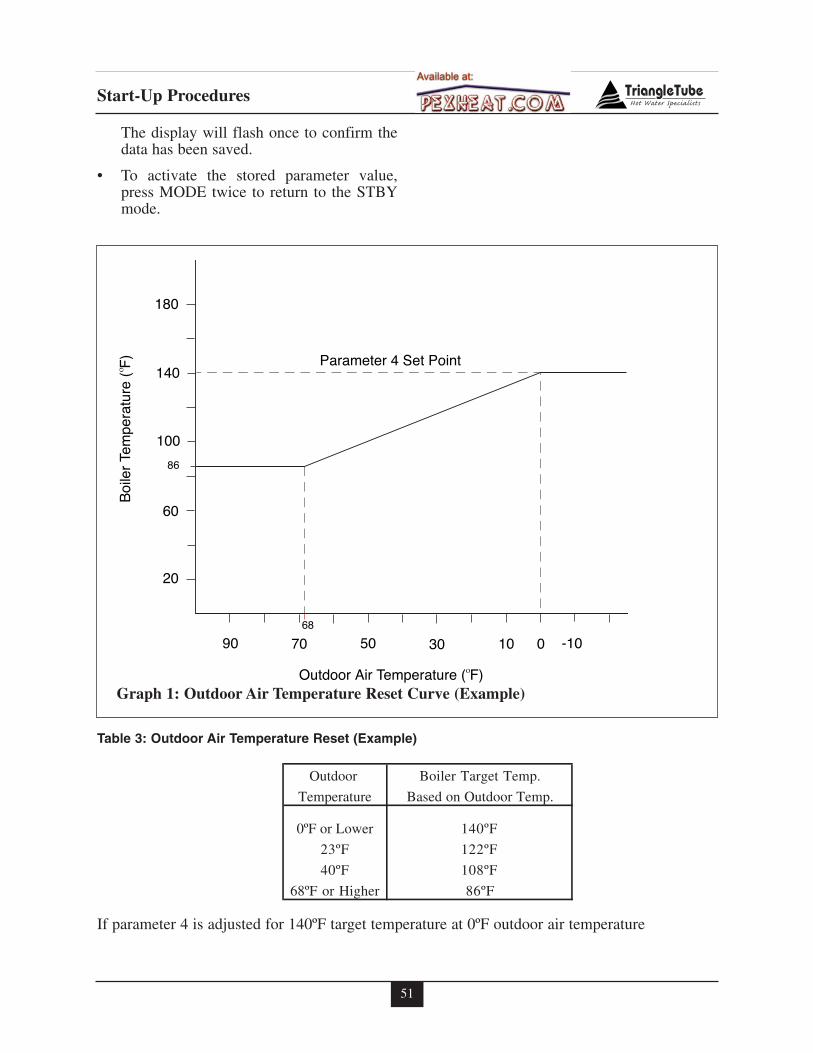
51
Start-Up Procedures
The display will flash once to confirm thedata has been saved.
• To activate the stored parameter value,press MODE twice to return to the STBYmode.
If parameter 4 is adjusted for 140ºF target temperature at 0ºF outdoor air temperature
Table 3: Outdoor Air Temperature Reset (Example)
90
20
60
100
140
180
7068
50 30 10 0 -10
86
Boi
ler
Tem
pera
ture
( F
)
Outdoor Air Temperature ( F)
Parameter 4 Set Point
Graph 1: Outdoor Air Temperature Reset Curve (Example)
Outdoor Boiler Target Temp.
Temperature Based on Outdoor Temp.
0ºF or Lower 140ºF
23ºF 122ºF
40ºF 108ºF
68ºF or Higher 86ºF
52
Check-Out Procedures
SECTION XI- Check-Out Procedures
Perform the following check-out proce-dures as outlined and check off items ascompleted. When procedures are com-pleted, the installer should complete theinstallation record on page 53.
Check-out Procedures
� Boiler system water chemistry checked andverified as outlined on page 37.
� The manual air vent (if used) is closed andany automatic air vents placed within thesystem are open one full turn.
� Air is purged from the heating zones andboiler system piping.
� Burner has been confirmed as properlyconfigured for Propane application, as out-lined on page 30 (If applicable).
� Thermostat circuit wiring checked and ver-ified that no voltage is present to the lowvoltage terminals as outlined on page 39.
� Operating Instructions on page 42 were fol-lowed during start-up.
� Combustion levels and flame pattern veri-fied as outlined on page 41.
� Measured the rate of input on Natural Gasas outlined on page 41.
� Checked the incoming gas pressure to thePrestige to ensure a minimum pressure of5”w.c during flow conditions to all gasappliances and a maximum pressure of13”w.c during non-flow conditions forNatural and Propane.
� Adjusted balancing valves and system limitcontrols to provide design temperatures tothe primary space heating system.
� In multiple zone applications, adjusted forcorrect flow of boiler water to each zone.
� Checked and verified room thermostat(s)function properly and the thermostat(s)heat anticipator (if used) was properly set.
� Observed several operating cycles forproper operation of the PRESTIGE and thesystem.
� Set the room thermostat(s) to the desiredroom temperature.
� Reviewed all instructions shipped with thePRESTIGE with the homeowner or main-tenance personnel.
� Completed the Installation Record on page53.
� Ensure all manuals and other documenta-tion are returned to the Installation enve-lope and given to the owner for safekeep-ing.
NOTICE
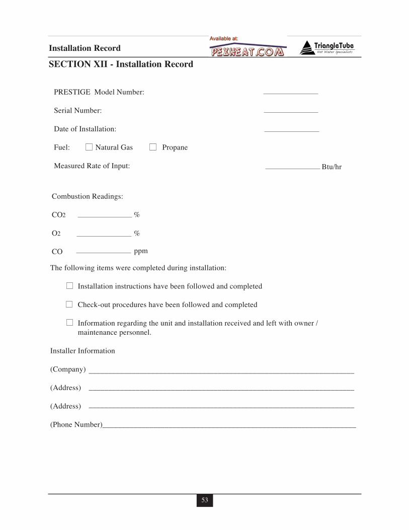
53
Installation Record
SECTION XII - Installation Record
�������������� ��������
������� ��������
��������������������
������������������ �������������������������������
������������������������������������������������������������
������
�����������������
���
��
���������������
� �����!����������!����"�������������������������
## ������������������"����� �$����������!�����"������
## � �"%&�����"������ �$����������!�����"������
## �������������������� ������������������������"��$����������!�� �!����'�
## ���������"����������(
�������������������
)�����*+
),����+
),����+
)� ��� �����+
���-��' �
....................................................................�
....................................................................�
....................................................................�
.................................................................
/
/
���
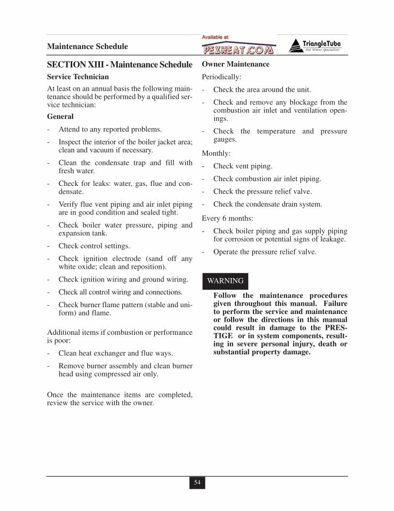
54
Maintenance Schedule
SECTION XIII - Maintenance ScheduleService Technician
At least on an annual basis the following main-tenance should be performed by a qualified ser-vice technician:
General
- Attend to any reported problems.
- Inspect the interior of the boiler jacket area;clean and vacuum if necessary.
- Clean the condensate trap and fill withfresh water.
- Check for leaks: water, gas, flue and con-densate.
- Verify flue vent piping and air inlet pipingare in good condition and sealed tight.
- Check boiler water pressure, piping andexpansion tank.
- Check control settings.
- Check ignition electrode (sand off anywhite oxide; clean and reposition).
- Check ignition wiring and ground wiring.
- Check all control wiring and connections.
- Check burner flame pattern (stable and uni-form) and flame.
Additional items if combustion or performanceis poor:
- Clean heat exchanger and flue ways.
- Remove burner assembly and clean burnerhead using compressed air only.
Once the maintenance items are completed,review the service with the owner.
Owner Maintenance
Periodically:
- Check the area around the unit.
- Check and remove any blockage from thecombustion air inlet and ventilation open-ings.
- Check the temperature and pressuregauges.
Monthly:
- Check vent piping.
- Check combustion air inlet piping.
- Check the pressure relief valve.
- Check the condensate drain system.
Every 6 months:
- Check boiler piping and gas supply pipingfor corrosion or potential signs of leakage.
- Operate the pressure relief valve.
Follow the maintenance proceduresgiven throughout this manual. Failureto perform the service and maintenanceor follow the directions in this manualcould result in damage to the PRES-TIGE or in system components, result-ing in severe personal injury, death orsubstantial property damage.
WARNING
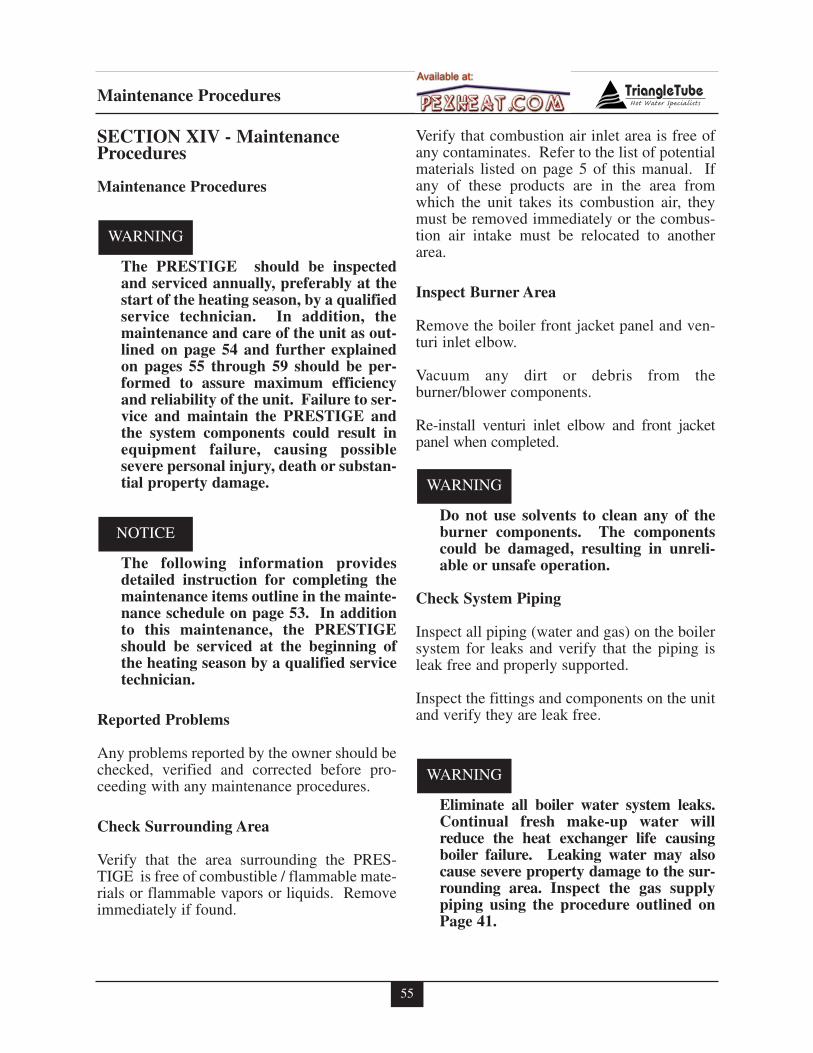
55
Maintenance Procedures
SECTION XIV - MaintenanceProcedures
Maintenance Procedures
The PRESTIGE should be inspectedand serviced annually, preferably at thestart of the heating season, by a qualifiedservice technician. In addition, themaintenance and care of the unit as out-lined on page 54 and further explainedon pages 55 through 59 should be per-formed to assure maximum efficiencyand reliability of the unit. Failure to ser-vice and maintain the PRESTIGE andthe system components could result inequipment failure, causing possiblesevere personal injury, death or substan-tial property damage.
The following information providesdetailed instruction for completing themaintenance items outline in the mainte-nance schedule on page 53. In additionto this maintenance, the PRESTIGEshould be serviced at the beginning ofthe heating season by a qualified servicetechnician.
Reported Problems
Any problems reported by the owner should bechecked, verified and corrected before pro-ceeding with any maintenance procedures.
Check Surrounding Area
Verify that the area surrounding the PRES-TIGE is free of combustible / flammable mate-rials or flammable vapors or liquids. Removeimmediately if found.
Verify that combustion air inlet area is free ofany contaminates. Refer to the list of potentialmaterials listed on page 5 of this manual. Ifany of these products are in the area fromwhich the unit takes its combustion air, theymust be removed immediately or the combus-tion air intake must be relocated to anotherarea.
Inspect Burner Area
Remove the boiler front jacket panel and ven-turi inlet elbow.
Vacuum any dirt or debris from theburner/blower components.
Re-install venturi inlet elbow and front jacketpanel when completed.
Do not use solvents to clean any of theburner components. The componentscould be damaged, resulting in unreli-able or unsafe operation.
Check System Piping
Inspect all piping (water and gas) on the boilersystem for leaks and verify that the piping isleak free and properly supported.
Inspect the fittings and components on the unitand verify they are leak free.
Eliminate all boiler water system leaks.Continual fresh make-up water willreduce the heat exchanger life causingboiler failure. Leaking water may alsocause severe property damage to the sur-rounding area. Inspect the gas supplypiping using the procedure outlined onPage 41.
WARNING
WARNING
NOTICE
WARNING
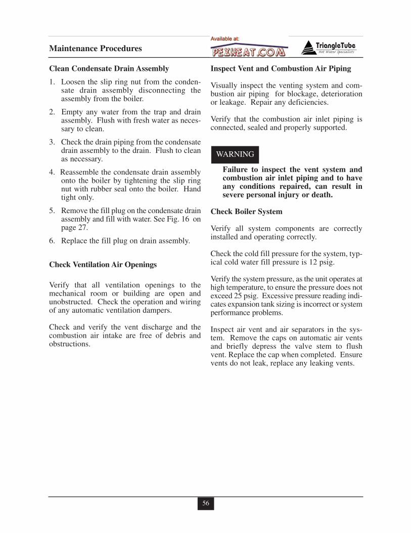
56
Maintenance Procedures
Clean Condensate Drain Assembly
1. Loosen the slip ring nut from the conden-sate drain assembly disconnecting theassembly from the boiler.
2. Empty any water from the trap and drainassembly. Flush with fresh water as neces-sary to clean.
3. Check the drain piping from the condensatedrain assembly to the drain. Flush to cleanas necessary.
4. Reassemble the condensate drain assemblyonto the boiler by tightening the slip ringnut with rubber seal onto the boiler. Handtight only.
5. Remove the fill plug on the condensate drainassembly and fill with water. See Fig. 16 onpage 27.
6. Replace the fill plug on drain assembly.
Check Ventilation Air Openings
Verify that all ventilation openings to themechanical room or building are open andunobstructed. Check the operation and wiringof any automatic ventilation dampers.
Check and verify the vent discharge and thecombustion air intake are free of debris andobstructions.
Inspect Vent and Combustion Air Piping
Visually inspect the venting system and com-bustion air piping for blockage, deteriorationor leakage. Repair any deficiencies.
Verify that the combustion air inlet piping isconnected, sealed and properly supported.
Failure to inspect the vent system andcombustion air inlet piping and to haveany conditions repaired, can result insevere personal injury or death.
Check Boiler System
Verify all system components are correctlyinstalled and operating correctly.
Check the cold fill pressure for the system, typ-ical cold water fill pressure is 12 psig.
Verify the system pressure, as the unit operates athigh temperature, to ensure the pressure does notexceed 25 psig. Excessive pressure reading indi-cates expansion tank sizing is incorrect or systemperformance problems.
Inspect air vent and air separators in the sys-tem. Remove the caps on automatic air ventsand briefly depress the valve stem to flushvent. Replace the cap when completed. Ensurevents do not leak, replace any leaking vents.
WARNING
57
Maintenance Procedures
Check Expansion Tank
Refer to Section IV - boiler piping for recom-mended location of the expansion tank andair eliminators.
Close -Type Tank:
- Ensure tank is partially filled withwater leaving an air gap as a cushion.Refer to the manufacturer’s instructionfor proper fill level.
- Ensure the tank is fitted with a devicethat reduces gravity circulation of air-saturated tank water back into the sys-tem. This device prevents air frombubbling up through the water as itreturns from the system.
- Ensure no automatic air vents are usedin the system. This will allow air toescape from the system instead ofreturning to the tank.
Diaphragm Tank:
- Ensure the system contains a minimum ofone automatic air vent. Recommendedlocation of the air vent should be atop anair eliminator.
- Remove the tank from the system andcheck the charge pressure. For residen-tial applications the charge pressure istypically 12 psig. If tank does not holda charge pressure, then the membrane isdamaged and the tank should bereplaced.
Check Boiler Relief Valve
Inspect the relief valve and lift the lever to ver-ify flow at least annually or as recommendedon the warning tag of the valve.
Before manually operating the pressurerelief valve, ensure the discharge piping isdirected to a suitable place of disposal toavoid a potential scald hazard. The dis-charge piping must be full size withoutrestriction and installed to permit com-plete drainage of both the valve and line.
If after closing the valve, the valve fails to seatproperly or continually weeps, replace therelief valve. Ensure the cause of the reliefvalve to weep is the valve itself, not due to sys-tem over-pressurization caused by an expan-sion tank that is waterlogged or undersized.
Inspection of Ignition Electrode
Remove the ignition electrode from the burnermounting plate.
Remove any white oxides accumulated on theelectrode using fine grit sandpaper or steel wool.If the electrode does not clean to a satisfactorycondition, replace the ignitor.
When replacing the ignition electrode, ensurethe gasket is in good condition and correctlypositioned.
Check Ignition Wiring and Ground Wiring
Inspect the burner wiring from the burner con-trol module to the ground terminal behind thecontrol panel.
Ensure wiring is in good condition and secure-ly connected.
Check ground continuity of the wiring to theboiler jacket or piping using a continuity meter.
Replace and correct ground wire if ground con-tinuity is not completed and satisfactory.
WARNING
58
Maintenance Procedures
Check Control Wiring
Inspect all control wiring. Ensure wiring is ingood condition and properly connected.
Check Control Settings
1. Set the control display to PARAMETERmode and check all boiler settings. Adjustsetting as necessary see page 47.
2. Check any external limit control settings (ifused). Adjust settings as necessary.
Perform Start-up and Checkout Procedures
Start the unit and perform the start-up proce-dure as listed in this manual.
Verify the cold water fill pressure is correct andthe operating pressure of the boiler is withinnormal operating range.
Complete the checkout procedures as refer-enced in this manual.
Check Burner Flame
Inspect the burner flame through the observa-tion port on the heat exchanger.
If flame pattern is not fully blue and covers theentire burner surface during high fire, shut theunit down and allow it to cool thoroughly.
Close the external manual gas valve on the gassupply line and disconnect the gas piping toremove the burner assembly from the unit.
Remove the burner head mounting screws andremove the burner head, carefully ensure com-bustion chamber insulation is not damaged.See warning on page 60. Inspect the burnerhead for deterioration. Use compressed air ora vacuum to clean the burner head.
Remove the venturi and gas valve assemblyfrom the blower.
Use the vacuum cleaner or compressed air toclean the interior of the blower assembly.Inspect the blower blades to ensure they areclean and not damaged.
Re-assemble the venturi and gas valve onto theblower. Ensure the venturi gasket is in goodcondition and positioned correctly.
Re-assemble the burner head onto the mount-ing plate. Ensure the burner head gasket is ingood condition and positioned correctly.
Re-assemble the gas supply connection andopen the external manual gas valve placing theunit back into service.
Check Flame Signal
The flame signal should be a min. 3µ Α −DC.
Check the ignitor for fouling or damagedinsulation if a low flame signal is read.
Check ground wiring and continuity as a causefor low flame signal. Replace ignitor if condi-tions are satisfactory.
Check Combustion Levels
Refer to page 41 of this manual for measuringcombustion levels and burner adjustments.
Check Flue Gas Temperature
1. Adjust the boiler to fire at HIGH fire andplace the control display to INFORMATIONmode, see pages 45 and 47 for procedures.
2. The flue gas temperature is indicated on thedisplay as the first digit of 5. The measuredtemperature (shown as the last 3 digits)should not be more than 54ºF higher thanthe measured supply water temperature.
3. The measured supply water temperature isindicated on the information display as thefirst digit of 1 and the temperature shownas the last 3 digits.
59
Maintenance Procedures
4. If the measured flue gas temperature ishigher than 54ºF over the supply watertemperature, shut the boiler down and fol-low the procedures listed below to cleanthe heat exchanger.
Clean Heat Exchanger
1. Shut down the boiler:
- Follow the instructions on Page 42 "ToTurn Off Gas to Appliance"
- Do not drain the boiler unless the boil-er will be subject to freezing condi-tions.
- Do not drain the boiler if freeze protec-tion fluid is used in the system.
2. Allow the boiler to cool down to room tem-perature before servicing.
3. Disconnect the gas piping to the boiler.
4. Remove the mounting nuts securing theburner plate to the heat exchanger and setaside.
5. Carefully remove the burner assembly,burner plate and combustion chamber insu-lation from the heat exchanger and setaside. See warning on page 60.
6. Use a vacuum cleaner or compressed air orwater to remove any accumulation fromthe heat exchanger flue ways. Do not useany solvent.
7. Reinstall the burner assembly, burner plateand combustion chamber insulation ontothe heat exchanger. Ensure the plate gasketand combustion chamber insulation is inplace and not damaged. See warning onpage 60.
8. Tighten the mounting nuts onto the burnerplate. Do not use excessive force in tight-ening.
9. Reconnect the gas piping and check forleaks.
10. Close isolation valves on the boiler waterpiping to isolate the boiler from the heatingsystem.
11. Attach a hose to the boiler drain valve andflush the boiler thoroughly with freshwater by using the purge valves to allowwater to enter through the make-up waterline to the boiler.
12. Once the boiler has been completelyflushed, return the boiler and system pipingback to operation.
13. Perform the required startup and checkoutprocedures as outlined on pages 37 to 52.
Review With Owner
Ensure the owner understands the impor-tance to perform the maintenance schedulespecified in this manual.
Remind the owner of the importance to calla licensed contractor should the unit or sys-tem exhibit any unusual behavior.
60
Maintenance Procedures
The combustion chamber insulationcontains ceramic fibers, which are clas-sified as a possible human carcinogen.When exposed to extremely high tem-peratures, the ceramic fibers, whichcontain crystalline silica, can be con-verted into cristobalite.
Avoid Breathing and Contact with Skinand Eyes
When removing or repairing the combustionchamber insulation follow these precautionmeasures:
1. Use a NIOSH approved respirator whichmeets OSHA requirements for cristobalitedust, similar to N95. Contact NIOSH at1-800-356-4676 or on the web atwww.cdc.gov/niosh for latest recommen-dations.
2. Wear long sleeved, loose fitting clothing,gloves and eyes protection.
3. Assure adequate ventilation.
4. Wash with soap and water after contact.
5. Wash potentially contaminated clothesseparately from other laundry and rinsewashing machine thoroughly.
6. Discard used insulation in an air tightplastic bag.
NIOSH Stated First Aid:Eye/Skin: Immediately irrigateBreathing: Clean fresh air
WARNING
Handling Previously Fired Combustion Chamber Insulation
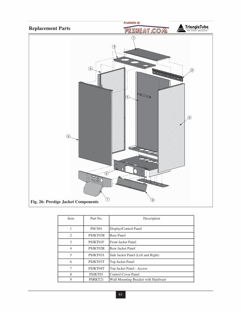
61
Replacement Parts
5
9
91
2
3
5
4
6
7
Item Part No. Description
1 PSCS01 Display/Control Panel
2 PSJKT03B Base Panel
3 PSJKT01F Front Jacket Panel
4 PSJKT02R Rear Jacket Panel
5 PSJKT01S Side Jacket Panel (Left and Right)
6 PSJKT03T Top Jacket Panel
7 PSJKT04T Top Jacket Panel - Access
8 PSJKT03 Control Cover Panel
9 PSRKT21 Wall Mounting Bracket with Hardware
Fig. 26: Prestige Jacket Components
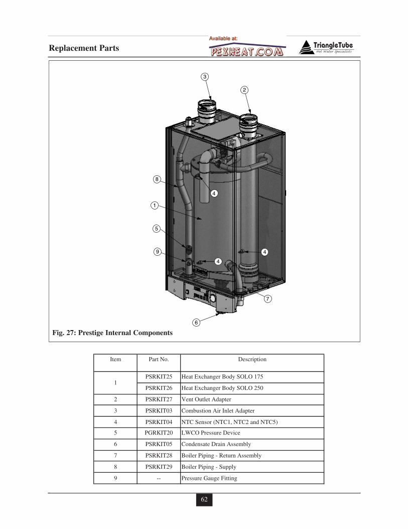
62
Replacement Parts
7
4
4
4
9
8
6
1
3
2
5
Item Part No. Description
PSRKIT25 Heat Exchanger Body SOLO 175
PSRKIT26 Heat Exchanger Body SOLO 250
2 PSRKIT27 Vent Outlet Adapter
3 PSRKIT03 Combustion Air Inlet Adapter
4 PSRKIT04 NTC Sensor (NTC1, NTC2 and NTC5)
5 PGRKIT20 LWCO Pressure Device
6 PSRKIT05 Condensate Drain Assembly
7 PSRKIT28 Boiler Piping - Return Assembly
8 PSRKIT29 Boiler Piping - Supply
9 -- Pressure Gauge Fitting
1
Fig. 27: Prestige Internal Components
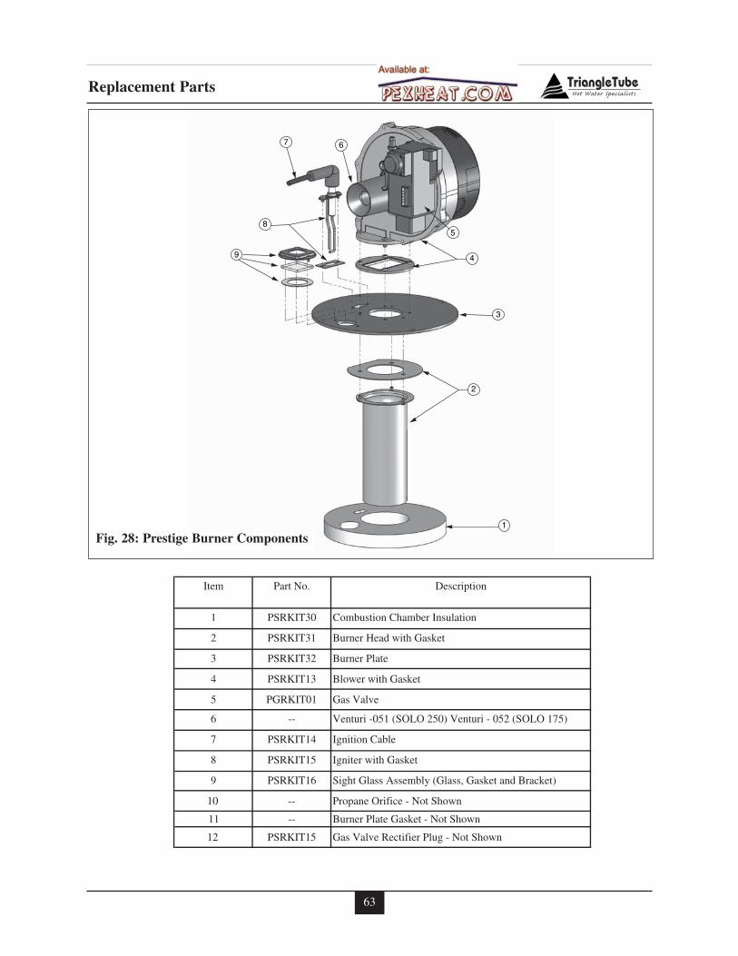
63
5
2
4
8
1
3
9
67
Item Part No. Description
1 PSRKIT30 Combustion Chamber Insulation
2 PSRKIT31 Burner Head with Gasket
3 PSRKIT32 Burner Plate
4 PSRKIT13 Blower with Gasket
5 PGRKIT01 Gas Valve
6 -- Venturi -051 (SOLO 250) Venturi - 052 (SOLO 175)
7 PSRKIT14 Ignition Cable
8 PSRKIT15 Igniter with Gasket
9 PSRKIT16 Sight Glass Assembly (Glass, Gasket and Bracket)
10 -- Propane Orifice - Not Shown
11 -- Burner Plate Gasket - Not Shown
12 PSRKIT15 Gas Valve Rectifier Plug - Not Shown
Fig. 28: Prestige Burner Components
Replacement Parts
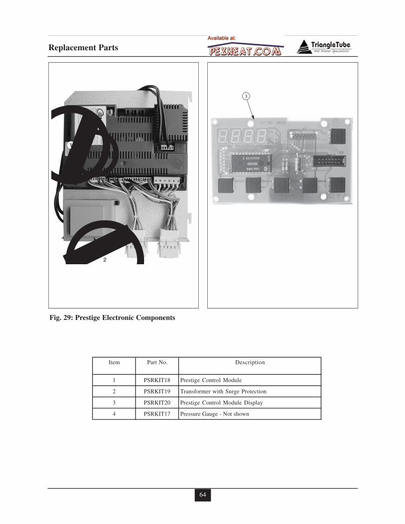
64
1
2
Item Part No. Description
1 PSRKIT18 Prestige Control Module
2 PSRKIT19 Transformer with Surge Protection
3 PSRKIT20 Prestige Control Module Display
4 PSRKIT17 Pressure Gauge - Not shown
3
Fig. 29: Prestige Electronic Components
Replacement Parts
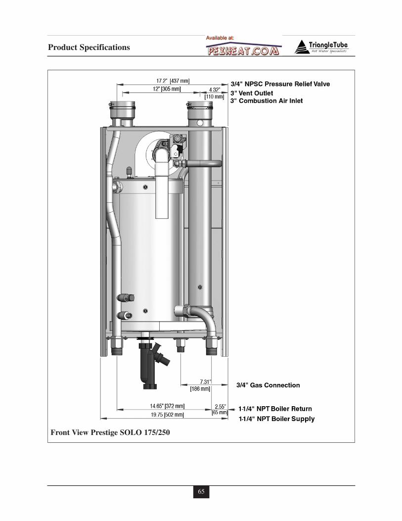
65
Product Specifications
Front View Prestige SOLO 175/250
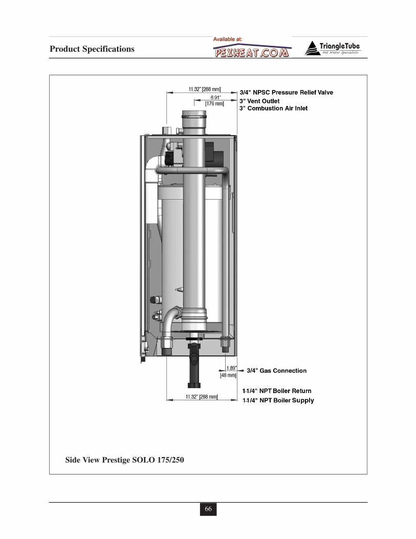
66
Product Specifications
Side View Prestige SOLO 175/250
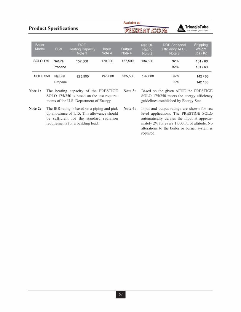
67
Product Specifications
FuelDOE
Heating CapacityNote 1
InputNote 4
OutputNote 4
DOE SeasonalEfficiency AFUE
Note 3
Net IBRRatingNote 2
157,500 170,000 157,500 92%
ShippingWeight
Lbs / Kg
131 / 60Natural
BoilerModel
SOLO 175 134,500
102,500 110,000 102,500 92% 131 / 60Propane 87,000
225,500 245,000 225,500 92% 142 / 65NaturalSOLO 250 192,000
102,500 110,000 102,500 92% 142 / 65Propane 87,000
Note 1: The heating capacity of the PRESTIGESOLO 175/250 is based on the test require-ments of the U.S. Department of Energy.
Note 2: The IBR rating is based on a piping and pickup allowance of 1.15. This allowance shouldbe sufficient for the standard radiationrequirements for a building load.
Note 3: Based on the given AFUE the PRESTIGESOLO 175/250 meets the energy efficiencyguidelines established by Energy Star.
Note 4: Input and output ratings are shown for sealevel applications. The PRESTIGE SOLOautomatically derates the input at approxi-mately 2% for every 1,000 Ft. of altitude. Noalterations to the boiler or burner system isrequired.
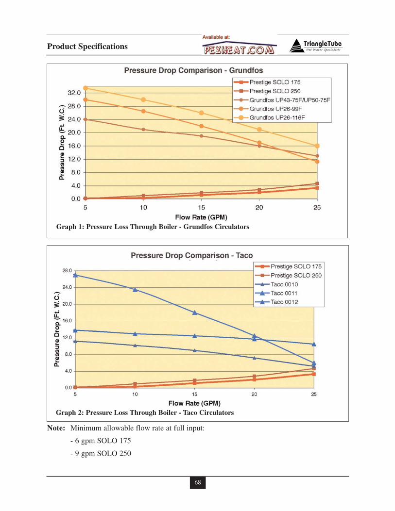
68
Product Specifications
Graph 1: Pressure Loss Through Boiler - Grundfos Circulators
Note: Minimum allowable flow rate at full input:
- 6 gpm SOLO 175
- 9 gpm SOLO 250
Graph 2: Pressure Loss Through Boiler - Taco Circulators

Additional quality water heating equipment availablefrom
Triangle Tube/Phase III
- Exclusive Tank-in-Tank design- Stainless steel construction- Available in 8 sizes and 2 models- Limited LIFETIME residential warranty- 15 year limited commercial warranty- Self cleaning/self descaling design
TTP Brazed Plate Heat Exchangers
- For domestic water, snow melting, radiant floor,refrigeration
- Plates made of stainless steel, with a 99.9 % copperand brazed, ensuring a high resistance to corrosion
- Self cleaning and self descaling- Computerized sizing available from Triangle
Tube/Phase III- Available in capacities from 25,000 BTU/hr to
5,000,000 BTU/hr
Phase III Indirect Fired Water Heaters
Freeway Center - 1 Triangle Lane - Blackwood, NJ 08012Tel: (856) 228 8881 - Fax: (856) 228 3584http://www.triangle tube.comE-mail: Info@triangle tube.com
Member of
Group
Heat Master Series Water Heaters
- Stainless steel construction- Oil and Gas fired- A unique design that eliminates the problem of scal-
ing found with traditional water heaters- Inputs ranging from 100,000 BTU/hr to 382,000
BTU/hr- Capable of 180º continuous production- 10 year non-prorated warranty- ETL Laboratories listed- ASME version available