Embed Size (px)
Citation preview
1
PRESTRESSED CONCRETE STRUCTURES
Amlan K. Sengupta, PhD PE
Department of Civil Engineering,
Indian Institute of Technology Madras
Module – 2: Losses in Prestress
Lecture – 08: Elastic Shortening
Welcome back to Prestressed Concrete Structures. Today, we are starting the second
module on losses in prestress.
(Refer Time Slide: 01:23)
In the first lecture of this module, we shall first get familiar with the notations in the
geometric properties and load variables. Next, we shall go through the first type of loss in
prestressed concrete structures, that is the elastic shortening. We shall understand the
phenomenon of elastic shortening for pre-tensioned and post-tensioned members. In
either type of the prestressed structures, we shall look into examples of axial members
and bending members.
2
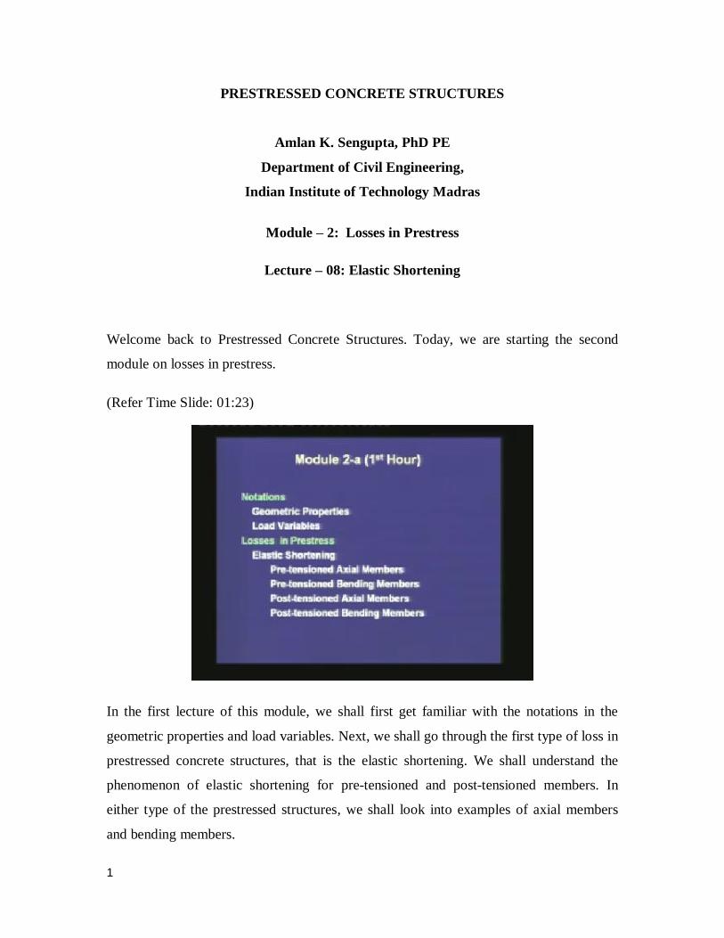
(Refer Time Slide: 02:05)
The commonly used geometric properties of the prestressed members are explained in
this slide. Ac is the area of the concrete section, that is given the total sectional area of the
member, if we subtract the area of the prestressing steel, then the remaining area is
termed as ‘Ac’. There can be of course substantial difference between Ac and the total
area A, if the duct is voided and its size is large. The second notation is Ap, which is the
area of prestressing steel, that is the total cross-sectional area of the tendons. The third is
the area of the prestressed member, which is the summation of Ac and Ap.
3
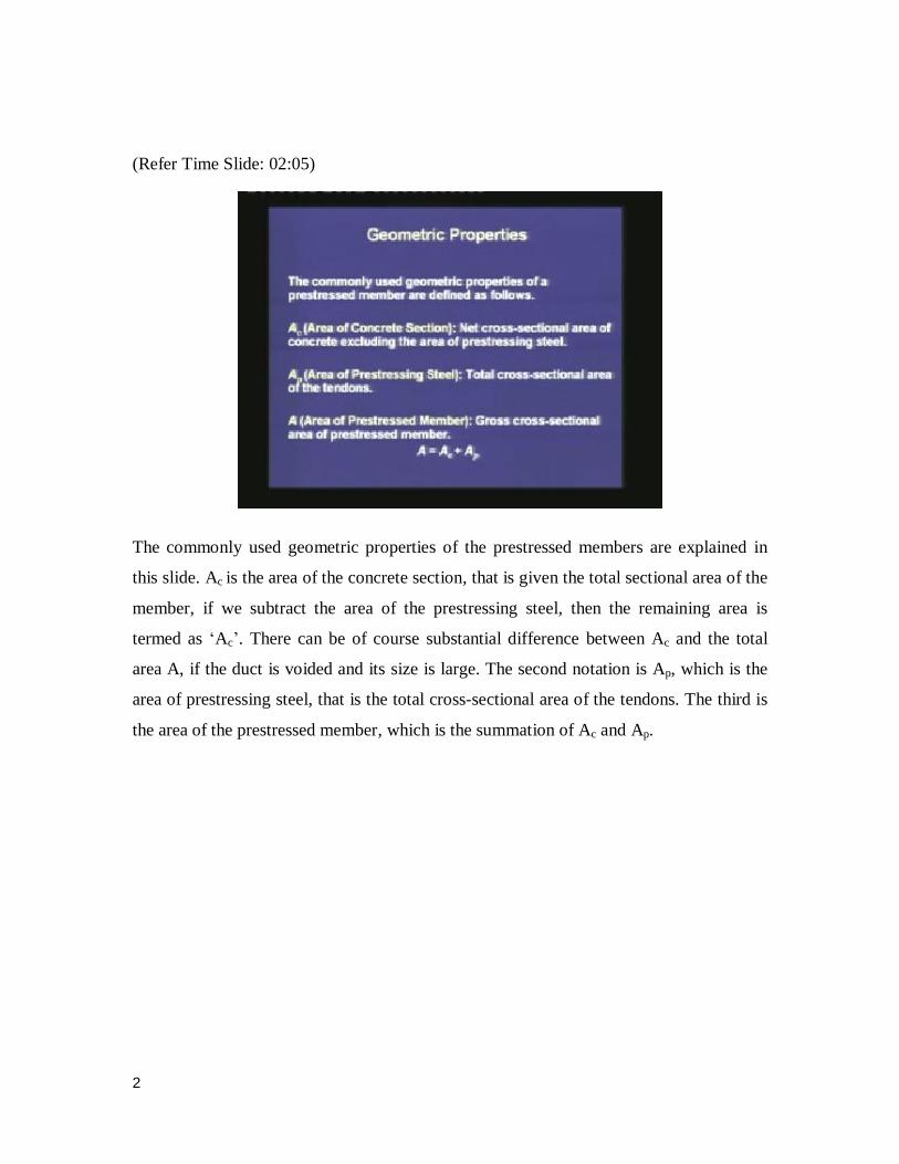
(Refer Time Slide: 03:08)
There is another definition which is used in elastic analysis, that is the transformed area
of the prestressed member. This is the area of the member when the steel is substituted by
an equivalent area of concrete. The transformed area is given as Ac plus the modular ratio
times the area of the prestressing steel. If we substitute back the expression of the total
area, then the transformed area is given as the total area plus the modular ratio minus 1
times Ap. The modular ratio is defined as the ratio of the elastic modulus of the
prestressing steel divided by the elastic modulus of the concrete.
The modulus of concrete can change with time. In our elastic analysis, we may stick to
the short-term elastic modulus. Then, the modular ratio is defined just based on the short-
term elastic modulus. If we use the long-term elastic modulus of concrete, we are
including the effect of creep in the definition of modular ratio of the member.
4
(Refer Time Slide: 04:37)
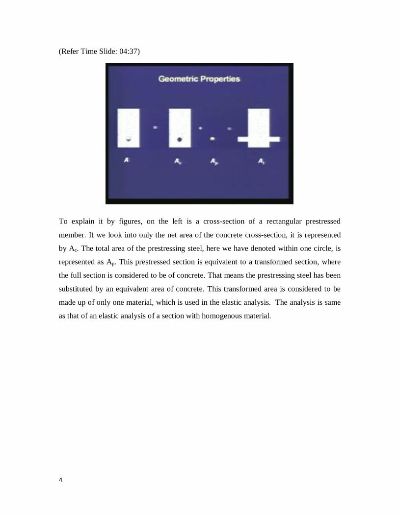
To explain it by figures, on the left is a cross-section of a rectangular prestressed
member. If we look into only the net area of the concrete cross-section, it is represented
by Ac. The total area of the prestressing steel, here we have denoted within one circle, is
represented as Ap. This prestressed section is equivalent to a transformed section, where
the full section is considered to be of concrete. That means the prestressing steel has been
substituted by an equivalent area of concrete. This transformed area is considered to be
made up of only one material, which is used in the elastic analysis. The analysis is same
as that of an elastic analysis of a section with homogenous material.
5
(Refer Time Slide: 05:41)
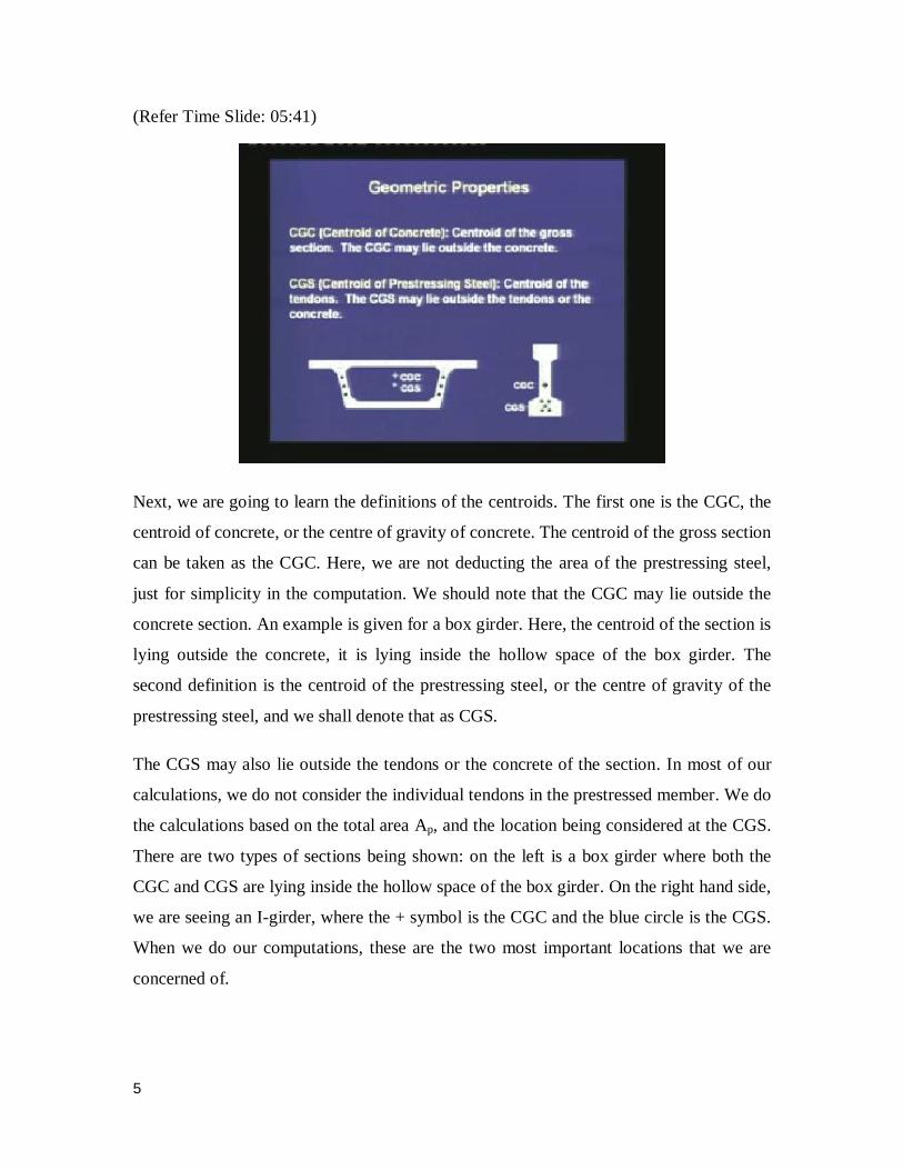
Next, we are going to learn the definitions of the centroids. The first one is the CGC, the
centroid of concrete, or the centre of gravity of concrete. The centroid of the gross section
can be taken as the CGC. Here, we are not deducting the area of the prestressing steel,
just for simplicity in the computation. We should note that the CGC may lie outside the
concrete section. An example is given for a box girder. Here, the centroid of the section is
lying outside the concrete, it is lying inside the hollow space of the box girder. The
second definition is the centroid of the prestressing steel, or the centre of gravity of the
prestressing steel, and we shall denote that as CGS.
The CGS may also lie outside the tendons or the concrete of the section. In most of our
calculations, we do not consider the individual tendons in the prestressed member. We do
the calculations based on the total area Ap, and the location being considered at the CGS.
There are two types of sections being shown: on the left is a box girder where both the
CGC and CGS are lying inside the hollow space of the box girder. On the right hand side,
we are seeing an I-girder, where the + symbol is the CGC and the blue circle is the CGS.
When we do our computations, these are the two most important locations that we are
concerned of.
6
(Refer Time Slide: 07:47)
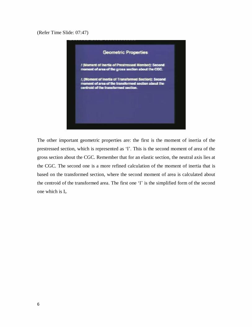
The other important geometric properties are: the first is the moment of inertia of the
prestressed section, which is represented as ‘I’. This is the second moment of area of the
gross section about the CGC. Remember that for an elastic section, the neutral axis lies at
the CGC. The second one is a more refined calculation of the moment of inertia that is
based on the transformed section, where the second moment of area is calculated about
the centroid of the transformed area. The first one ‘I’ is the simplified form of the second
one which is It.
7
(Refer Time Slide: 08:40)
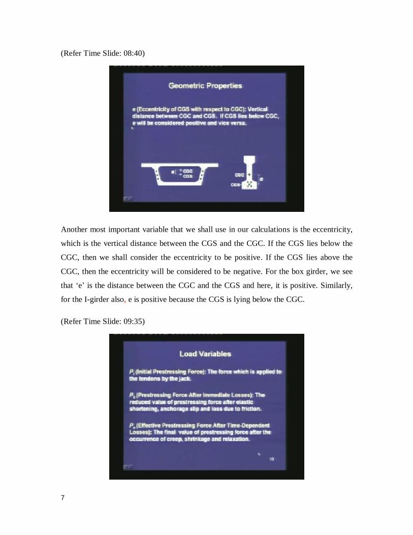
Another most important variable that we shall use in our calculations is the eccentricity,
which is the vertical distance between the CGS and the CGC. If the CGS lies below the
CGC, then we shall consider the eccentricity to be positive. If the CGS lies above the
CGC, then the eccentricity will be considered to be negative. For the box girder, we see
that ‘e’ is the distance between the CGC and the CGS and here, it is positive. Similarly,
for the I-girder also, e is positive because the CGS is lying below the CGC.
(Refer Time Slide: 09:35)
8
Among the load variables, Pi represents the initial prestressing force which is applied by
the jack. This force is recorded by the gauge in the jack. The second one is P0, which is
the prestressing force after immediate losses. That means, the actual prestressing force
that is transferred to the concrete section is lower than the value which is recorded by the
gauge in the jack. It is lower because of the immediate losses due to elastic shortening,
friction and seating of the anchorage, which we shall study subsequently. The third one
is Pe, which is the effective prestressing force after the time dependent losses. As we have
learnt earlier, the prestressing force drops with time and after several years, it gets
stabilised to a final value. That value will be referred to as the effective prestressing
force, and it will be denoted as Pe.
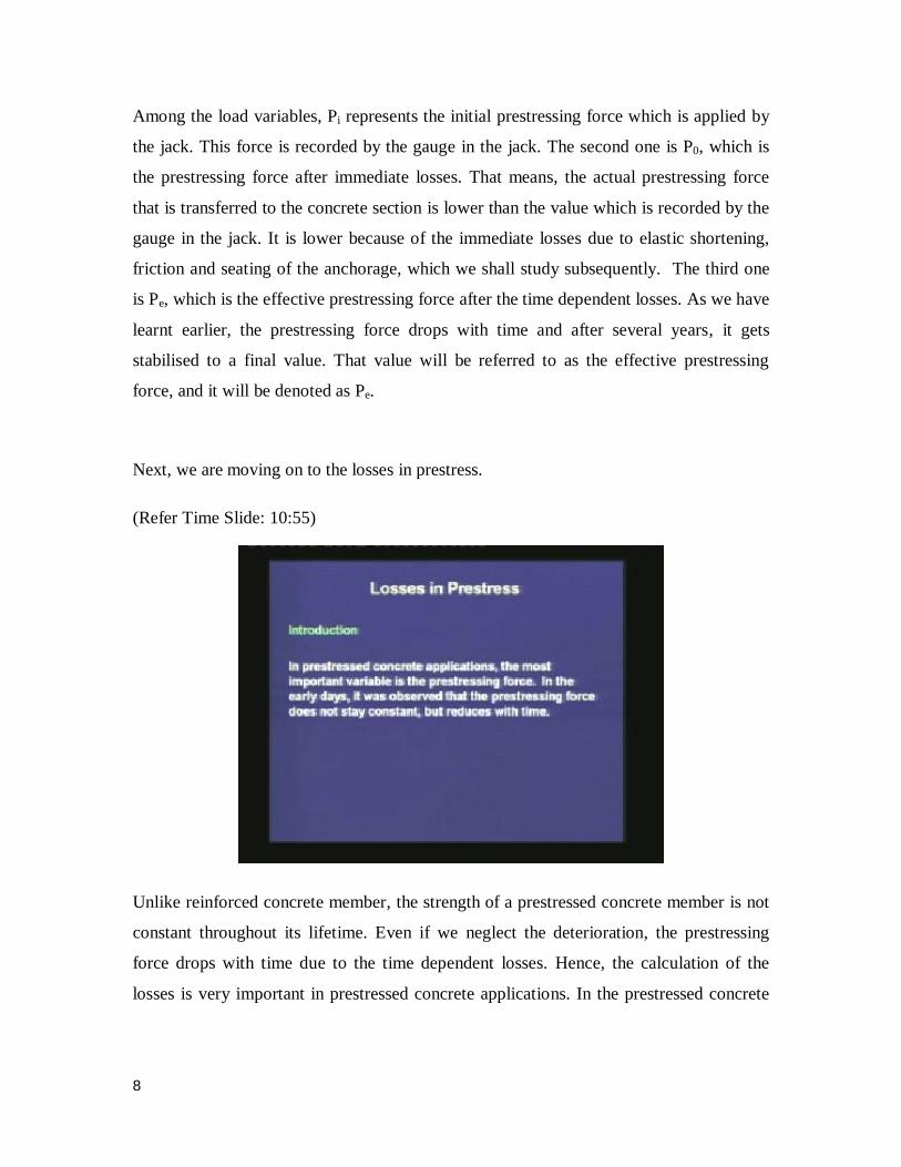
Next, we are moving on to the losses in prestress.
(Refer Time Slide: 10:55)
Unlike reinforced concrete member, the strength of a prestressed concrete member is not
constant throughout its lifetime. Even if we neglect the deterioration, the prestressing
force drops with time due to the time dependent losses. Hence, the calculation of the
losses is very important in prestressed concrete applications. In the prestressed concrete
9
applications, the most important variable is the prestressing force. In the earlier days, it
was observed that the prestressing force does not stay constant, but it reduces with time.
(Refer Time Slide: 11:41)
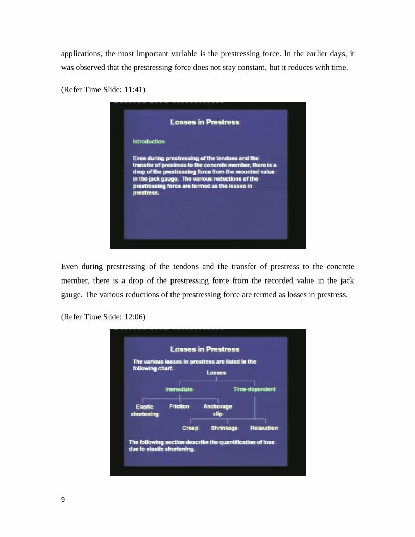
Even during prestressing of the tendons and the transfer of prestress to the concrete
member, there is a drop of the prestressing force from the recorded value in the jack
gauge. The various reductions of the prestressing force are termed as losses in prestress.
(Refer Time Slide: 12:06)
10
In this chart, we are trying to understand the various losses under different sections. The
losses in prestress can broadly be classified under two groups: one is the immediate
losses, which are shown on the left side. The other is the time dependent losses, which
takes several years till the prestressing force gets stabilized. Out of immediate losses, the
important one is the elastic shortening, which is the shortening of the concrete member
when the prestressing force is transferred to it. It is an immediate shortening. Then, the
second one is the friction. The friction is the drop in the prestressing force along the
length of the prestressing tendon, because of the curvature in the prestressing tendon. The
third one is the anchorage slip. After the jacks have pulled the tendons and the wedges
are placed, the tendons are released. At that instant, the wedges and the anchorage block
seat in the prestressed member. During the seating, there is some loss till the wedges get
locked in the anchorage block. The loss due to this seating of the anchorage is called the
‘anchorage slip’.
Among the time dependent losses, we have already studied the phenomena under the
material properties. Creep and shrinkage are typical behaviour of concrete. Creep is the
deformation with time under a constant load. Shrinkage is the deformation with time due
to loss of moisture. Relaxation is a property of the prestressing steel, which is the drop in
the stress under a constant strain, with time. In today’s lecture, the following section will
quantify the loss due to elastic shortening.
11
(Refer Time Slide: 14:22)
In pre-tensioned members, when the tendons are cut and the prestressing force is
transferred to the member, the concrete undergoes immediate shortening due to the
prestressing force. The tendons also shorten by the same amount, which leads to the loss
of prestress. The elastic shortening is more of a concern in a pre-tensioned member.
(Refer Time Slide: 14:51)
12
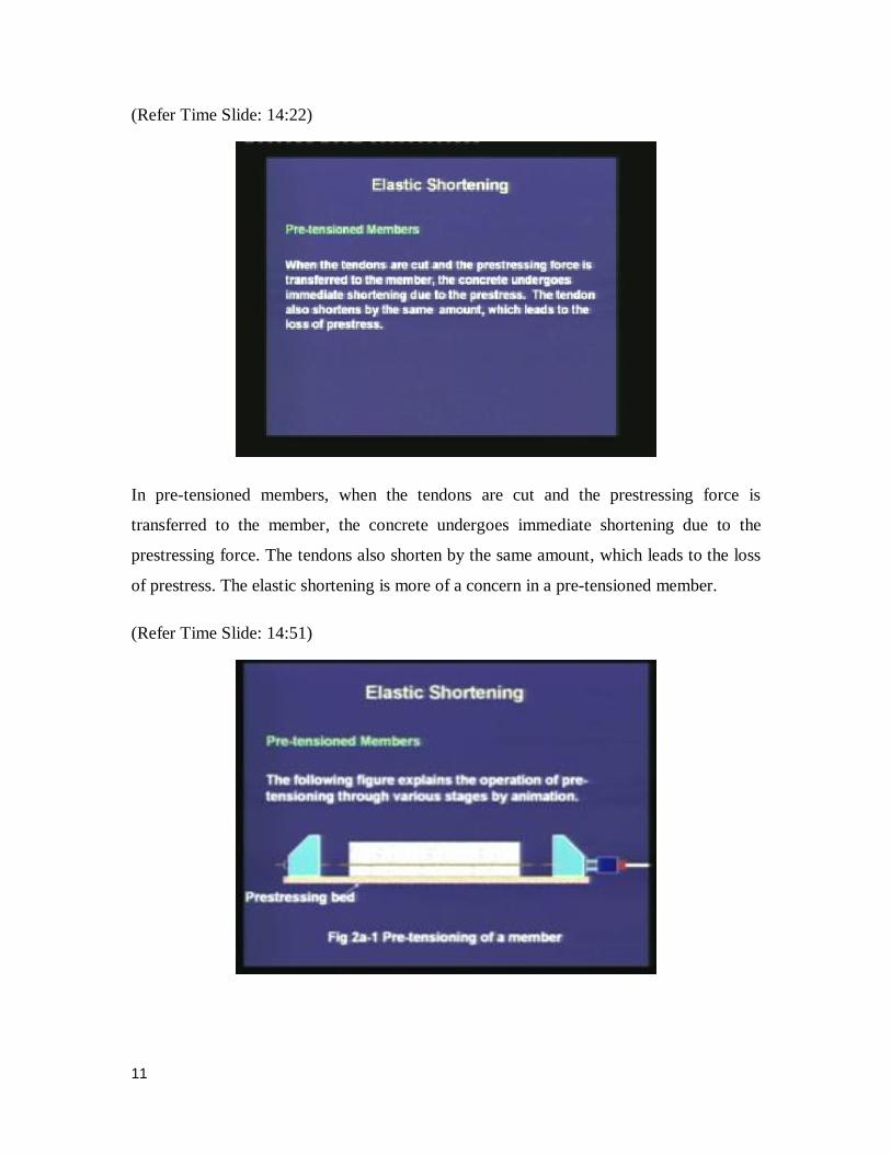
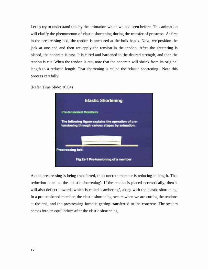
Let us try to understand this by the animation which we had seen before. This animation
will clarify the phenomenon of elastic shortening during the transfer of prestress. At first
in the prestressing bed, the tendon is anchored at the bulk heads. Next, we position the
jack at one end and then we apply the tension in the tendon. After the shuttering is
placed, the concrete is cast. It is cured and hardened to the desired strength, and then the
tendon is cut. When the tendon is cut, note that the concrete will shrink from its original
length to a reduced length. That shortening is called the ‘elastic shortening’. Note this
process carefully.
(Refer Time Slide: 16:04)
As the prestressing is being transferred, this concrete member is reducing in length. That
reduction is called the ‘elastic shortening’. If the tendon is placed eccentrically, then it
will also deflect upwards which is called ‘cambering’, along with the elastic shortening.
In a pre-tensioned member, the elastic shortening occurs when we are cutting the tendons
at the end, and the prestressing force is getting transferred to the concrete. The system
comes into an equilibrium after the elastic shortening.
13
(Refer Time Slide: 16:45)
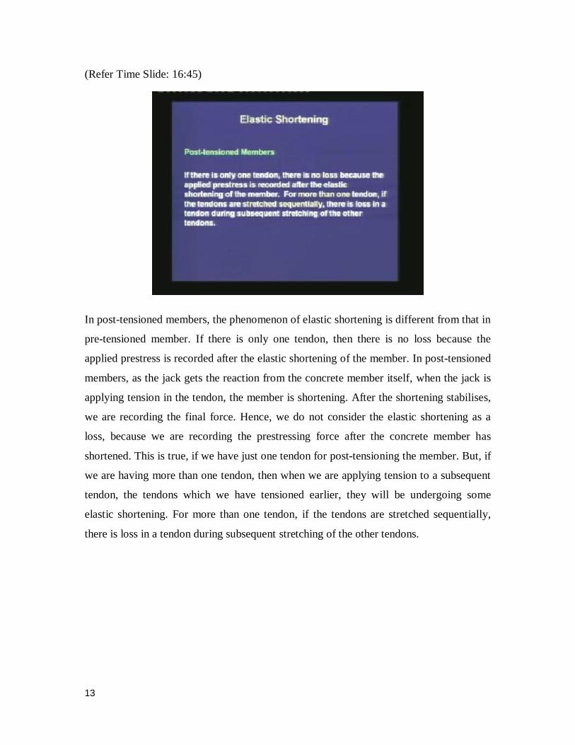
In post-tensioned members, the phenomenon of elastic shortening is different from that in
pre-tensioned member. If there is only one tendon, then there is no loss because the
applied prestress is recorded after the elastic shortening of the member. In post-tensioned
members, as the jack gets the reaction from the concrete member itself, when the jack is
applying tension in the tendon, the member is shortening. After the shortening stabilises,
we are recording the final force. Hence, we do not consider the elastic shortening as a
loss, because we are recording the prestressing force after the concrete member has
shortened. This is true, if we have just one tendon for post-tensioning the member. But, if
we are having more than one tendon, then when we are applying tension to a subsequent
tendon, the tendons which we have tensioned earlier, they will be undergoing some
elastic shortening. For more than one tendon, if the tendons are stretched sequentially,
there is loss in a tendon during subsequent stretching of the other tendons.
14
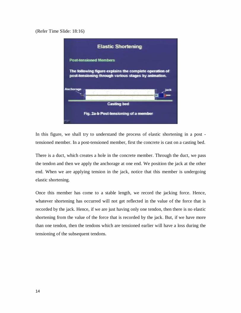
(Refer Time Slide: 18:16)
In this figure, we shall try to understand the process of elastic shortening in a post -
tensioned member. In a post-tensioned member, first the concrete is cast on a casting bed.
There is a duct, which creates a hole in the concrete member. Through the duct, we pass
the tendon and then we apply the anchorage at one end. We position the jack at the other
end. When we are applying tension in the jack, notice that this member is undergoing
elastic shortening.
Once this member has come to a stable length, we record the jacking force. Hence,
whatever shortening has occurred will not get reflected in the value of the force that is
recorded by the jack. Hence, if we are just having only one tendon, then there is no elastic
shortening from the value of the force that is recorded by the jack. But, if we have more
than one tendon, then the tendons which are tensioned earlier will have a loss during the
tensioning of the subsequent tendons.
15
(Refer Time Slide: 19:59)
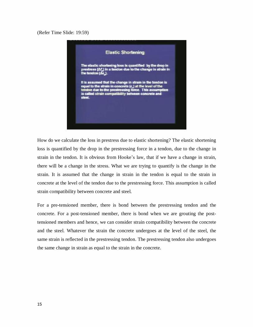
How do we calculate the loss in prestress due to elastic shortening? The elastic shortening
loss is quantified by the drop in the prestressing force in a tendon, due to the change in
strain in the tendon. It is obvious from Hooke’s law, that if we have a change in strain,
there will be a change in the stress. What we are trying to quantify is the change in the
strain. It is assumed that the change in strain in the tendon is equal to the strain in
concrete at the level of the tendon due to the prestressing force. This assumption is called
strain compatibility between concrete and steel.
For a pre-tensioned member, there is bond between the prestressing tendon and the
concrete. For a post-tensioned member, there is bond when we are grouting the post-
tensioned members and hence, we can consider strain compatibility between the concrete
and the steel. Whatever the strain the concrete undergoes at the level of the steel, the
same strain is reflected in the prestressing tendon. The prestressing tendon also undergoes
the same change in strain as equal to the strain in the concrete.

16
(Refer Time Slide: 21:23)
Our next step is how do we calculate the strain in the concrete? The calculations are
based on the prestressing force, which we are recording. The strain is calculated from the
stress that is generated in the concrete at the level of the prestressing steel, due to the
prestressing force. A linear elastic relationship is used to calculate the strain from the
stress. The following slide explains the quantification of the loss.
(Refer Time Slide: 22:04)

17
The drop in prestress is equal to the elastic modulus of the prestressing steel times the
change in strain. The change in strain in the prestressing tendon is equal to the strain in
the concrete. The strain in the concrete is equal to the stress in the concrete, divided by
the elastic modulus of the concrete. The ratio of the two elastic moduli, that of
prestressing steel divided by that of the concrete is denoted as the modular ratio ‘m’.
Hence, the basic equation to calculate the loss in prestress due to elastic shortening is
equal to the modular ratio times the stress in the concrete at the level of the tendon.
As we know that there need not be a single tendon, there can be several tendons in a
concrete member. For simplicity, the loss in all the tendons can be calculated based on
the stress in concrete at the level of CGS. Here comes the utility of the CGS, that we are
considering as if all the tendons are concentrated at that location. We are calculating the
stress in the concrete at the level of the CGS. From there, we are calculating the loss in
the prestress. This simplification cannot be used when the tendons are stretched
sequentially in a post-tensioned member, because in a post-tensioned member, the
calculation is more involved. It is a sequential process. Hence, we cannot club together
all the tendons to be located at the CGS.
Let us first look into the pre-tensioned axial members.
18
(Refer Time Slide: 24:01)
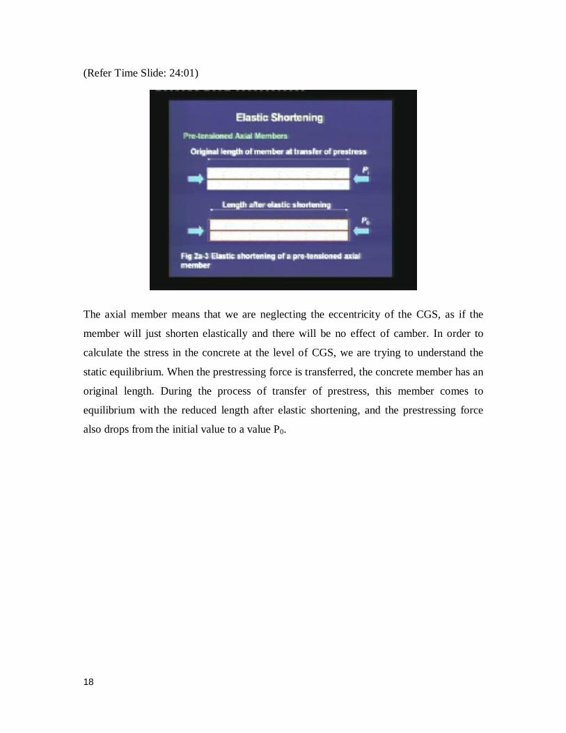
The axial member means that we are neglecting the eccentricity of the CGS, as if the
member will just shorten elastically and there will be no effect of camber. In order to
calculate the stress in the concrete at the level of CGS, we are trying to understand the
static equilibrium. When the prestressing force is transferred, the concrete member has an
original length. During the process of transfer of prestress, this member comes to
equilibrium with the reduced length after elastic shortening, and the prestressing force
also drops from the initial value to a value P0.
19
(Refer Time Slide: 24:56)
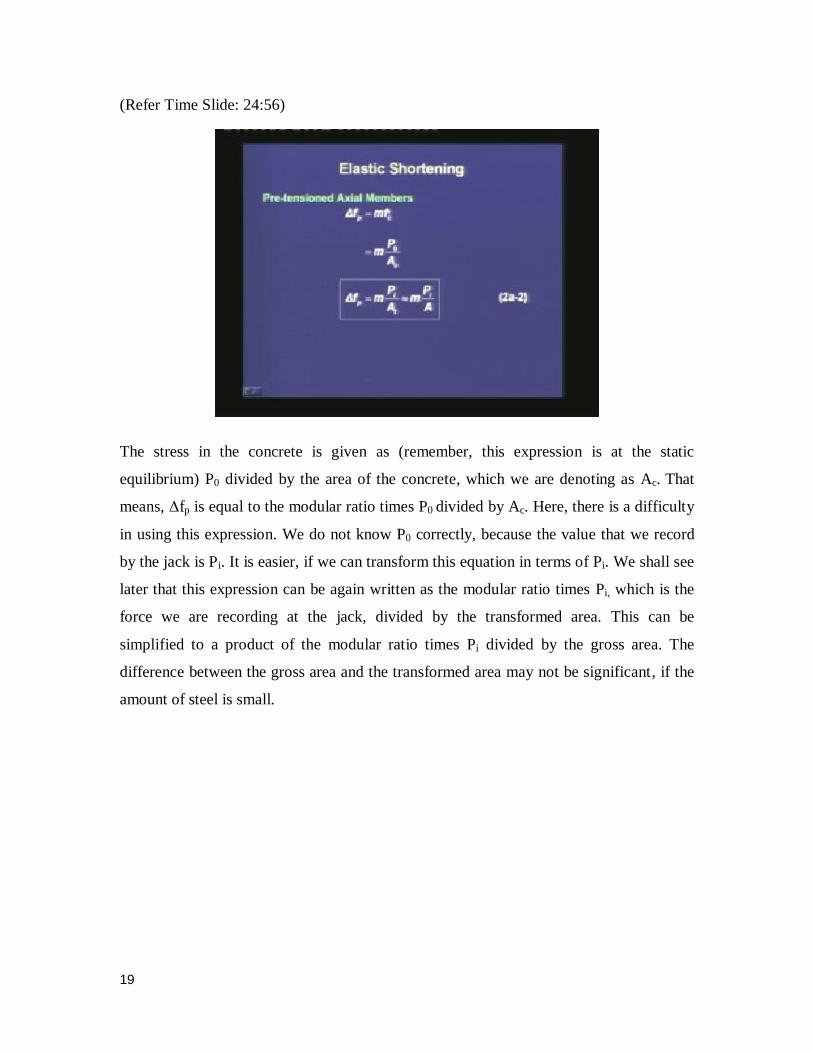
The stress in the concrete is given as (remember, this expression is at the static
equilibrium) P0 divided by the area of the concrete, which we are denoting as Ac. That
means, Δfp is equal to the modular ratio times P0 divided by Ac. Here, there is a difficulty
in using this expression. We do not know P0 correctly, because the value that we record
by the jack is Pi. It is easier, if we can transform this equation in terms of Pi. We shall see
later that this expression can be again written as the modular ratio times Pi, which is the
force we are recording at the jack, divided by the transformed area. This can be
simplified to a product of the modular ratio times Pi divided by the gross area. The
difference between the gross area and the transformed area may not be significant, if the
amount of steel is small.
20
(Refer Time Slide: 26:22)
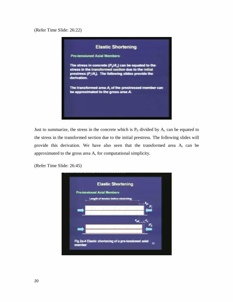
Just to summarize, the stress in the concrete which is P0 divided by Ac can be equated to
the stress in the transformed section due to the initial prestress. The following slides will
provide this derivation. We have also seen that the transformed area At can be
approximated to the gross area A, for computational simplicity.
(Refer Time Slide: 26:45)
21
We are trying to understand the change in strain due to the elastic shortening. When we
are stretching the steel, there is an initial strain in the prestressing strand. This strain is
calculated based on the original length of the tendon before stretching, and is denoted as
εpi. Next, after elastic shortening, the concrete undergoes a strain of εc. The final strain in
the prestressing steel is denoted as εp0, which is calculated from the final length of the
concrete member and the original length of the prestressing tendon.
(Refer Time Slide: 27:41)
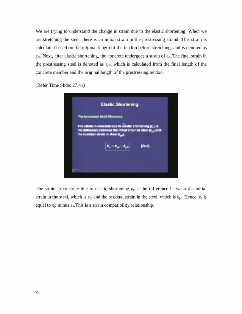
The strain in concrete due to elastic shortening εc is the difference between the initial
strain in the steel, which is εpi and the residual strain in the steel, which is εp0. Hence, εc is
equal to εpi minus ε0.This is a strain compatibility relationship.
22
(Refer Time Slide: 28:06)
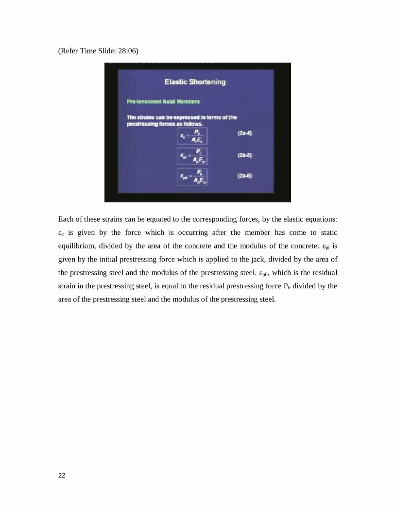
Each of these strains can be equated to the corresponding forces, by the elastic equations:
εc is given by the force which is occurring after the member has come to static
equilibrium, divided by the area of the concrete and the modulus of the concrete. εpi is
given by the initial prestressing force which is applied to the jack, divided by the area of
the prestressing steel and the modulus of the prestressing steel. εp0, which is the residual
strain in the prestressing steel, is equal to the residual prestressing force P0 divided by the
area of the prestressing steel and the modulus of the prestressing steel.
23
(Refer Time Slide: 28:58)
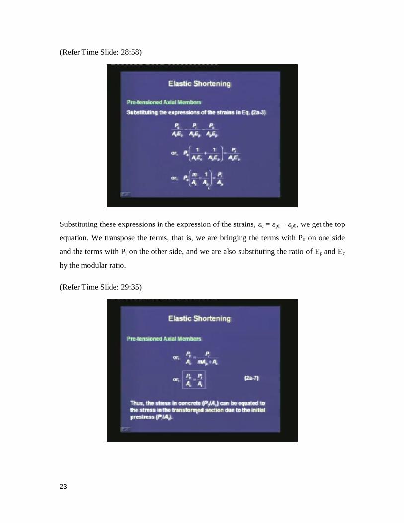
Substituting these expressions in the expression of the strains, εc = εpi εp0, we get the top
equation. We transpose the terms, that is, we are bringing the terms with P0 on one side
and the terms with Pi on the other side, and we are also substituting the ratio of Ep and Ec
by the modular ratio.
(Refer Time Slide: 29:35)
24
Once we do this transposition and substitution, we come to the expression which gives
the stress in the concrete (originally calculated based on the stress at transfer P0 divided
by Ac) equal to the initial prestress that we record by the jack gauges, divided by the
transformed area. This equation is helpful because, we do not need P0 any more, and we
are able to calculate using Pi. Hence, we can substitute Pi / At in place of P0 / Ac.
(Refer Time Slide: 30:21)
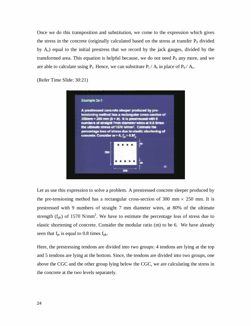
Let us use this expression to solve a problem. A prestressed concrete sleeper produced by
the pre-tensioning method has a rectangular cross-section of 300 mm 250 mm. It is
prestressed with 9 numbers of straight 7 mm diameter wires, at 80% of the ultimate
strength (fpk) of 1570 N/mm2. We have to estimate the percentage loss of stress due to
elastic shortening of concrete. Consider the modular ratio (m) to be 6. We have already
seen that fpi is equal to 0.8 times fpk.
Here, the prestressing tendons are divided into two groups: 4 tendons are lying at the top
and 5 tendons are lying at the bottom. Since, the tendons are divided into two groups, one
above the CGC and the other group lying below the CGC, we are calculating the stress in
the concrete at the two levels separately.
25
(Refer Time Slide: 31:48)
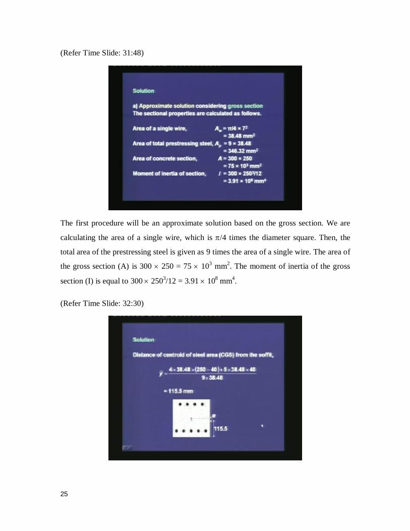
The first procedure will be an approximate solution based on the gross section. We are
calculating the area of a single wire, which is /4 times the diameter square. Then, the
total area of the prestressing steel is given as 9 times the area of a single wire. The area of
the gross section (A) is 300 250 = 75 103 mm
2. The moment of inertia of the gross
section (I) is equal to 300 2503/12 = 3.91 10
8 mm
4.
(Refer Time Slide: 32:30)
26
Once we know these geometric properties, we can calculate the location of the centroid
of the steel. This expression comes from the concept of the first moment of area. That is,
we are calculating the location of the CGS, by calculating the location of each of the
tendons. Once we get the location of the CGS, we can calculate the eccentricity, which is
the distance between the CGS and the CGC. Here, for the gross rectangular cross-section,
the CGC is at the centre. What we can see is that, the CGS is located 115 mm from the
bottom. Since there are 4 tendons at the top and 5 tendons at the bottom, the CGS is
shifted a little bit down from the CGC.
(Refer Time Slide: 33:43)
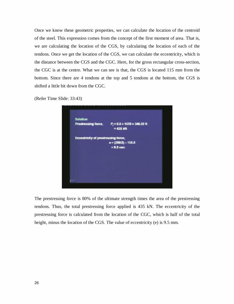
The prestressing force is 80% of the ultimate strength times the area of the prestressing
tendons. Thus, the total prestressing force applied is 435 kN. The eccentricity of the
prestressing force is calculated from the location of the CGC, which is half of the total
height, minus the location of the CGS. The value of eccentricity (e) is 9.5 mm.
27
(Refer Time Slide: 34:21)
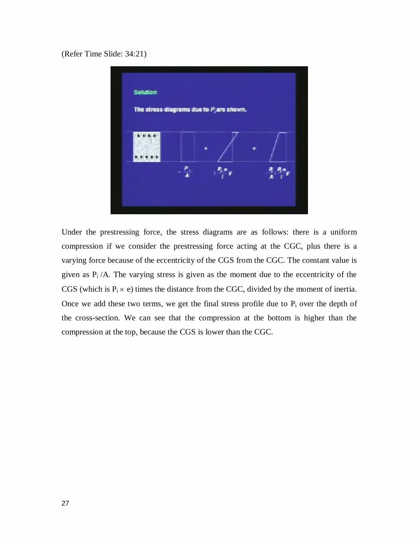
Under the prestressing force, the stress diagrams are as follows: there is a uniform
compression if we consider the prestressing force acting at the CGC, plus there is a
varying force because of the eccentricity of the CGS from the CGC. The constant value is
given as Pi /A. The varying stress is given as the moment due to the eccentricity of the
CGS (which is Pi e) times the distance from the CGC, divided by the moment of inertia.
Once we add these two terms, we get the final stress profile due to Pi over the depth of
the cross-section. We can see that the compression at the bottom is higher than the
compression at the top, because the CGS is lower than the CGC.
28
(Refer Time Slide: 35:31)
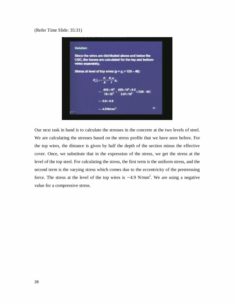
Our next task in hand is to calculate the stresses in the concrete at the two levels of steel.
We are calculating the stresses based on the stress profile that we have seen before. For
the top wires, the distance is given by half the depth of the section minus the effective
cover. Once, we substitute that in the expression of the stress, we get the stress at the
level of the top steel. For calculating the stress, the first term is the uniform stress, and the
second term is the varying stress which comes due to the eccentricity of the prestressing
force. The stress at the level of the top wires is 4.9 N/mm2. We are using a negative
value for a compressive stress.
29
(Refer Time Slide: 36:39)
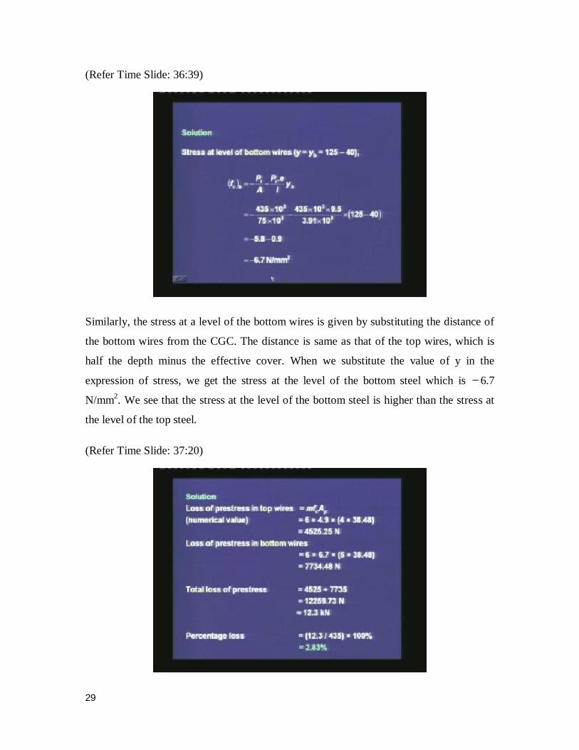
Similarly, the stress at a level of the bottom wires is given by substituting the distance of
the bottom wires from the CGC. The distance is same as that of the top wires, which is
half the depth minus the effective cover. When we substitute the value of y in the
expression of stress, we get the stress at the level of the bottom steel which is 6.7
N/mm2. We see that the stress at the level of the bottom steel is higher than the stress at
the level of the top steel.
(Refer Time Slide: 37:20)
30
Once we have calculated the stresses in concrete at the level of the steel, we are
calculating the losses in the tendons at each level. The loss of prestress in the top wires is
equal to the modular ratio times the stress in the concrete, times the area of the
prestressing steel at the top. We are multiplying the drop in the prestress times the area of
the prestressing steel, to get the total loss in the prestressing force. Similarly, we can
calculate the loss of prestress in the bottom wires, which is the modular ratio times the
stress in concrete, times the area of the prestressing steel at the bottom. The total loss of
prestress is summation of the two terms, that is 12.3 kN. Our original prestressing force
was 435 kN. From that, we have lost 12.3 kN due to the elastic shortening. The
percentage loss due to elastic shortening is given as 12.3 divided by 435 times 100, which
is 2.83%. We have lost 2.83% of the prestressing force due to elastic shortening.
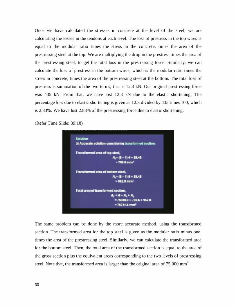
(Refer Time Slide: 39:18)
The same problem can be done by the more accurate method, using the transformed
section. The transformed area for the top steel is given as the modular ratio minus one,
times the area of the prestressing steel. Similarly, we can calculate the transformed area
for the bottom steel. Then, the total area of the transformed section is equal to the area of
the gross section plus the equivalent areas corresponding to the two levels of prestressing
steel. Note that, the transformed area is larger than the original area of 75,000 mm2.
31
(Refer Time Slide: 40:03)
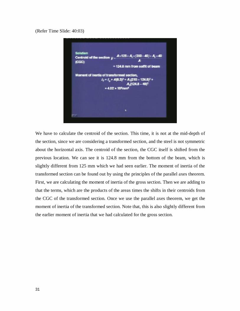
We have to calculate the centroid of the section. This time, it is not at the mid-depth of
the section, since we are considering a transformed section, and the steel is not symmetric
about the horizontal axis. The centroid of the section, the CGC itself is shifted from the
previous location. We can see it is 124.8 mm from the bottom of the beam, which is
slightly different from 125 mm which we had seen earlier. The moment of inertia of the
transformed section can be found out by using the principles of the parallel axes theorem.
First, we are calculating the moment of inertia of the gross section. Then we are adding to
that the terms, which are the products of the areas times the shifts in their centroids from
the CGC of the transformed section. Once we use the parallel axes theorem, we get the
moment of inertia of the transformed section. Note that, this is also slightly different from
the earlier moment of inertia that we had calculated for the gross section.
32
(Refer Time Slide: 41:31)
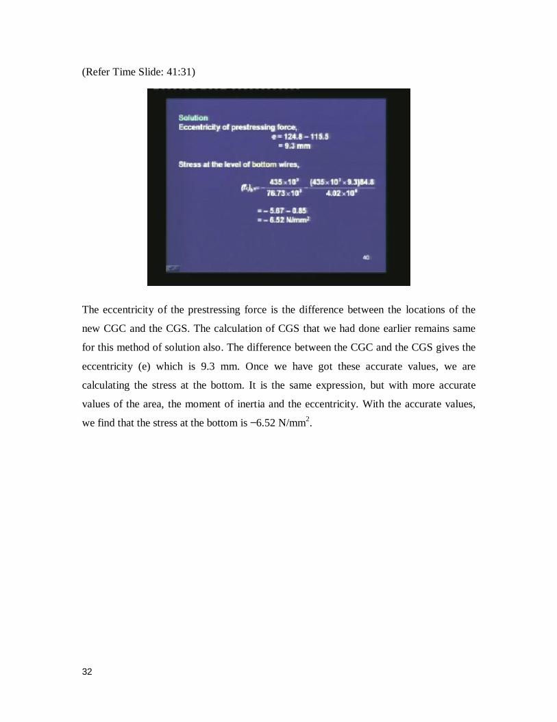
The eccentricity of the prestressing force is the difference between the locations of the
new CGC and the CGS. The calculation of CGS that we had done earlier remains same
for this method of solution also. The difference between the CGC and the CGS gives the
eccentricity (e) which is 9.3 mm. Once we have got these accurate values, we are
calculating the stress at the bottom. It is the same expression, but with more accurate
values of the area, the moment of inertia and the eccentricity. With the accurate values,
we find that the stress at the bottom is 6.52 N/mm2.
33
(Refer Time Slide: 42:18)
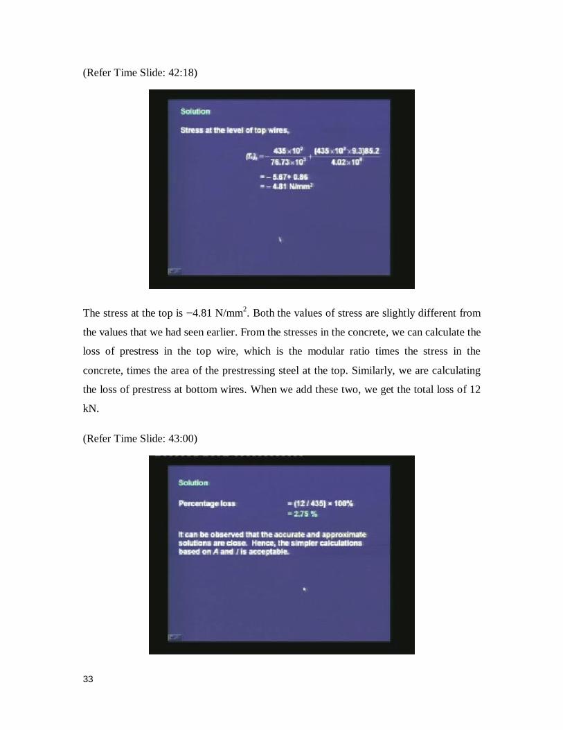
The stress at the top is 4.81 N/mm2. Both the values of stress are slightly different from
the values that we had seen earlier. From the stresses in the concrete, we can calculate the
loss of prestress in the top wire, which is the modular ratio times the stress in the
concrete, times the area of the prestressing steel at the top. Similarly, we are calculating
the loss of prestress at bottom wires. When we add these two, we get the total loss of 12
kN.
(Refer Time Slide: 43:00)
34
The percentage loss is 12 divided by 435 times 100, which is 2.75%. It can be observed
that the accurate and approximate solutions are very close. Hence, the simpler
calculations which are based on the area and the moment of inertia of the gross section,
are acceptable. The additional accuracy that we get by using the area and the moment of
inertia of the transformed section may not be warranted, because it leads to more
computation. The solution that we get based on the gross section is sufficiently good.
We are quickly reviewing the calculation of the loss for the other types of members.
(Refer Time Slide: 44:02)
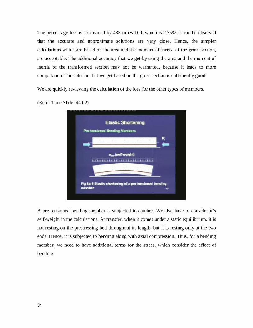
A pre-tensioned bending member is subjected to camber. We also have to consider it’s
self-weight in the calculations. At transfer, when it comes under a static equilibrium, it is
not resting on the prestressing bed throughout its length, but it is resting only at the two
ends. Hence, it is subjected to bending along with axial compression. Thus, for a bending
member, we need to have additional terms for the stress, which consider the effect of
bending.
35
(Refer Time Slide: 44:42)
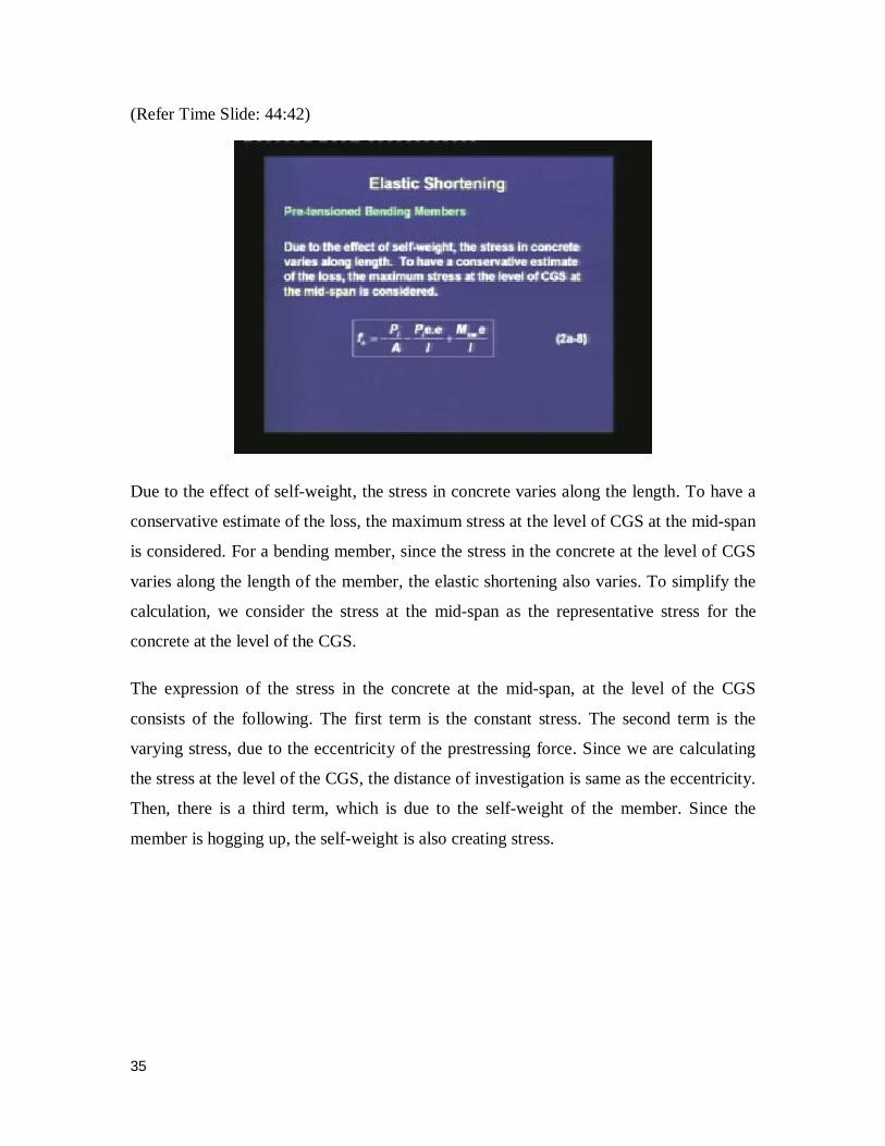
Due to the effect of self-weight, the stress in concrete varies along the length. To have a
conservative estimate of the loss, the maximum stress at the level of CGS at the mid-span
is considered. For a bending member, since the stress in the concrete at the level of CGS
varies along the length of the member, the elastic shortening also varies. To simplify the
calculation, we consider the stress at the mid-span as the representative stress for the
concrete at the level of the CGS.
The expression of the stress in the concrete at the mid-span, at the level of the CGS
consists of the following. The first term is the constant stress. The second term is the
varying stress, due to the eccentricity of the prestressing force. Since we are calculating
the stress at the level of the CGS, the distance of investigation is same as the eccentricity.
Then, there is a third term, which is due to the self-weight of the member. Since the
member is hogging up, the self-weight is also creating stress.

36
(Refer Time Slide: 46:19)
In the earlier expression, Msw is the moment at mid-span due to the self-weight. The
precise result using At and It of the transformed section, in place of A and I of the gross
section, is not computationally warranted. In the above example, the eccentricity of the
CGS was assumed to be constant throughout the length of the member.
Next, we move on to the post-tensioned axial members.
(Refer Time Slide: 46:59)
37
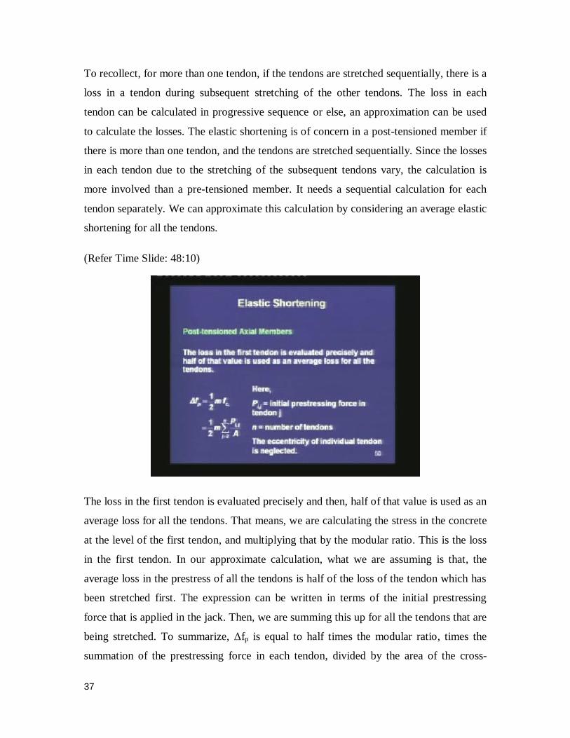
To recollect, for more than one tendon, if the tendons are stretched sequentially, there is a
loss in a tendon during subsequent stretching of the other tendons. The loss in each
tendon can be calculated in progressive sequence or else, an approximation can be used
to calculate the losses. The elastic shortening is of concern in a post-tensioned member if
there is more than one tendon, and the tendons are stretched sequentially. Since the losses
in each tendon due to the stretching of the subsequent tendons vary, the calculation is
more involved than a pre-tensioned member. It needs a sequential calculation for each
tendon separately. We can approximate this calculation by considering an average elastic
shortening for all the tendons.
(Refer Time Slide: 48:10)
The loss in the first tendon is evaluated precisely and then, half of that value is used as an
average loss for all the tendons. That means, we are calculating the stress in the concrete
at the level of the first tendon, and multiplying that by the modular ratio. This is the loss
in the first tendon. In our approximate calculation, what we are assuming is that, the
average loss in the prestress of all the tendons is half of the loss of the tendon which has
been stretched first. The expression can be written in terms of the initial prestressing
force that is applied in the jack. Then, we are summing this up for all the tendons that are
being stretched. To summarize, Δfp is equal to half times the modular ratio, times the
summation of the prestressing force in each tendon, divided by the area of the cross-

38
section. The summation is done from 2 to the total number of tendons (n). The
summation starts from 2, to consider the tendons stretched subsequent to the first tendon.
(Refer Time Slide: 50:28)
For a post-tensioned bending member, the procedure is similar. The calculation of loss
for tendons stretched sequentially is similar to that of the post-tensioned axial members.
For curved profiles, the eccentricity of the CGS and hence, the stress in concrete at the
level of CGS varies along the length. This is another complication for a post-tensioned
member, since usually the eccentricity varies along the length of the member. Most of the
time, the profiles of the tendons are parabolic, that means the eccentricity at the mid-span
is different from the rest of the length. To consider an average elastic shortening over the
full length of the member, an average stress in the concrete can be considered.
39
(Refer Time Slide: 51:25)
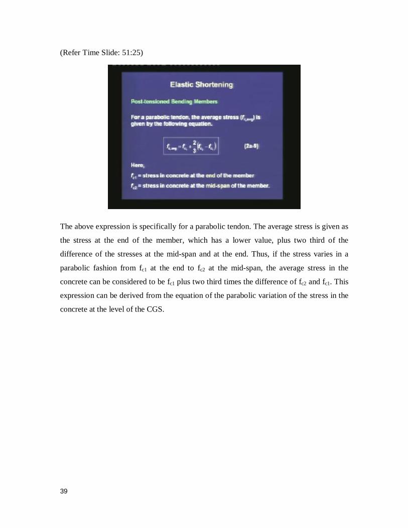
The above expression is specifically for a parabolic tendon. The average stress is given as
the stress at the end of the member, which has a lower value, plus two third of the
difference of the stresses at the mid-span and at the end. Thus, if the stress varies in a
parabolic fashion from fc1 at the end to fc2 at the mid-span, the average stress in the
concrete can be considered to be fc1 plus two third times the difference of fc2 and fc1. This
expression can be derived from the equation of the parabolic variation of the stress in the
concrete at the level of the CGS.
40
(Refer Time Slide: 52:38)
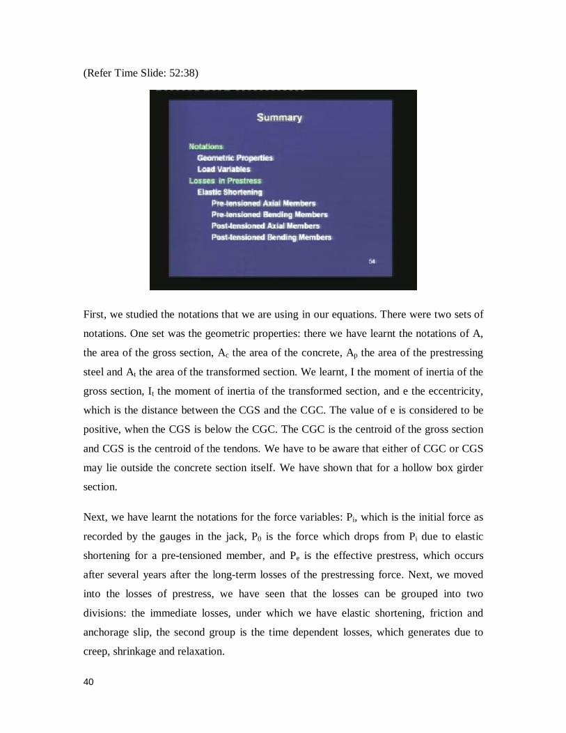
First, we studied the notations that we are using in our equations. There were two sets of
notations. One set was the geometric properties: there we have learnt the notations of A,
the area of the gross section, Ac the area of the concrete, Ap the area of the prestressing
steel and At the area of the transformed section. We learnt, I the moment of inertia of the
gross section, It the moment of inertia of the transformed section, and e the eccentricity,
which is the distance between the CGS and the CGC. The value of e is considered to be
positive, when the CGS is below the CGC. The CGC is the centroid of the gross section
and CGS is the centroid of the tendons. We have to be aware that either of CGC or CGS
may lie outside the concrete section itself. We have shown that for a hollow box girder
section.
Next, we have learnt the notations for the force variables: Pi, which is the initial force as
recorded by the gauges in the jack, P0 is the force which drops from Pi due to elastic
shortening for a pre-tensioned member, and Pe is the effective prestress, which occurs
after several years after the long-term losses of the prestressing force. Next, we moved
into the losses of prestress, we have seen that the losses can be grouped into two
divisions: the immediate losses, under which we have elastic shortening, friction and
anchorage slip, the second group is the time dependent losses, which generates due to
creep, shrinkage and relaxation.

41
In today’s lecture, we covered the first immediate loss, which is due to the elastic
shortening. We saw that this is of a concern for pre-tensioned members. We saw the
example of a pre-tensioned axial member in details. The calculations of a problem
showed that, if we use the properties of a gross section, the values are close enough
compared to the value which is derived by considering a transformed section. Hence, in
our subsequent calculations we shall use the gross section instead of the transformed
section for a member. Then we saw the expression of loss for a pre-tensioned bending
member where, the eccentricity of the prestressing force and the stress created due to the
self-weight of the member should also be included.
For a post-tensioned member, we have seen that if there is a single tendon then we need
not have to consider any loss due to elastic shortening, because the force in the jack is
recorded after the elastic shortening has occurred. But, if there is more than one tendon,
and if the tendons are stretched sequentially, then there will be losses in the tendons
which are stretched earlier and the calculation of the loss is done sequentially for each
tendon.
The process can be simplified, if we consider an average loss for all the tendons, which
are stretched sequentially. The average loss is given in terms of the loss in the tendon
which is tensioned first, and the average loss is considered to be half that is seen in the
first tendon. In calculating the stress of the concrete at the level of the CGS, we do the
summation for all the tendons, except the first one. Hence, the summation is from 2 to the
total number of tendons. Like that, we get an approximate expression of the loss due to
elastic shortening in post-tensioned members, where the tendons are stretched
sequentially. In a post-tensioned member, if the tendons have a parabolic profile, then the
computation becomes a bit more involved. The eccentricity varies along the length of the
member and hence, the stress also varies along the length of the member. For a parabolic
profile, we have seen a simplified expression for an average value of the stress in the
concrete. It is an average between the stress at the end and the stress at the mid-span.
From the average value of the stress in the concrete at the level of CGS, we can calculate
an average loss in prestress in a post-tensioned bending member.
42
To summarize, elastic shortening needs to be calculated for a pre-tensioned member
because the pre-tension force drops from the value applied by the jacks. It needs to be
calculated for a post-tensioned member, when there is more than one tendon and the
tendons are stretched sequentially. In our next lecture, we shall move on to the other two
types of immediate losses, which are due to the friction and the anchorage slip.
Thank you.