Embed Size (px)
Citation preview
Prestudy of utility polesin fiber composite
Master of Science Thesis
Nina Rigby
Stockholm 2008
TRITA-AVE 2007:71

1
Preface
This master thesis is a prestudy of the usage of fiber composite as material in 220 kVutility poles. The thesis has been done on behalf of Svenska Kraftnät.
I would like to thank Lillemor Carlshem of Svenska Kraftnät, who offered theopportunity to make this thesis and her role as instructor. I also would like to thank thefollowing persons at KTH, who have helped me in various questions throughout thethesis work: My examiner Malin Åkermo as well as teachers Per Wennhage and StefanHallström, all at the department of Aeronautical and Vehicle Engineering, Royal Instituteof Technology (KTH).
Stockholm 2008-05-15
Nina Rigby
2
Abstract
The job requestor for the thesis work has been Svenska Kraftnät; the Swedish state utilitywhich runs and administers the national electrical grid. Svenska Kraftnät is interested infinding suitable alternatives in terms of material for utility poles, which traditionally havebeen made of wood. Wooden utility poles are difficult to find for heights more than 20meters. Poles of wood are also subject to wood peckers. Furthermore, a possible futureban of creosote may pose an obstacle to use wooden poles.
The aim of this thesis work has been to look at the possibilities of using fiber compositeas material for 220 kV line utility poles. The thesis work has been done in form of aprestudy.
The work has been performed as literature studies based on books, articles and internetsearches. Calculations have been carried out using Euler methods and classic beamtheory to estimate the material thickness of a utility pole. The calculations have beenbased on load cases, loads and deflection boundaries provided by Svenska Kraftnät.
There are four utility pole manufactures in North America. Most of the fiber compositeutility poles are present in North America. According to manufacturers, their poles willlast 40 to 80 years and the poles are resistant to biological factors like fungus orwoodpeckers.
The materials currently used for fiber composite utility poles are combinations of glassfibers and polymer based thermoset resins such as polyester, vinylester or polyurethane.The utility pole manufacturers have chosen different resins for their specific product butall of manufacturers have chosen glass fiber as reinforcement material.
The fibers in the composite determine the mechanical properties due to their strength andmodulus. The values of the mechanical properties of the fibers are often one to twodegrees higher than the corresponding values of the matrix. The material of choice forutility poles is glass fiber due to its combination of good general properties and costefficiency. In order to choose a resin for the utility pole further work should be done,based on more specific requirement specifications.
As a result of the load case of beam bending, i.e. transverse and longitudinal loads, thepole should be braced in order to meet the requirements of maximum deflection. It isnoteworthy that also a wooden pole would need to be braced in order to fulfill theserequirements. When bracing the pole the maximum vertical load will be thedimensioning load for the material thickness.
As of today, there are no recycling industries present that can take care of fibercomposite material. This is however an area currently subject to research. Of the methodsbeing discussed in this report, the fluidised bed process is the only method being able torecover and recycle the fibers. The other methods are based upon milling or combustionof the material, the remains then being used as fillers or reinforcement in other materials.

3
Sammanfattning
Uppdragsgivaren till detta examensarbete har varit Svenska Kraftnät, ett statligt bolagvars uppgift är att driva och förvalta de nationella elkraftnätet. Svenska Kraftnät ärintresserade av kraftledningsstolpar i alternativa material. Stolpar har hittills varit av trä.Materialförsörjningen av trästolpar högre än 20 meter är dock svår och hackspettar ärdessutom ett problem vid användandet av trästolpar. Ett möjligt framtida förbud motkreosot kan vara ett hinder för fortsatt användande av trästoplar.
Syftet med detta examensarbete har varit att undersöka möjligheterna att användafiberkompositer som material för 220 kV kraftledningsstolpar.
Arbetet har utförts som en litteraturstudie, baserat på böcker, artiklar och sökningar påinternet. Beräkningar har utförts genom Eulers knäckningsfall och klassisk balkteori, föratt kunna uppskatta nödvändig materialtjocklek på en kraftledningsstolpe. Beräkningarnahar varit baserade på indata från Svenska Kraftnät gällande lastfall, laster samtutböjningstoleranser.
Det finns i nuläget fyra tillverkare av kraftledningsstolpar av fiberkomposit inordamerika, där även de flesta stolpar av fiberkomposit återfinns. Enligt tillverkarnasegna uppgifter kommer deras stolpar att hålla i 40 till 80 år. De påverkas dessutom inteav biologiska faktorer som röta eller hackspettar.
De material som i dagsläget används för kraftledningsstolpar av fiberkomposit är olikakombinationer av glasfiber och härdplaster, såsom polyester, vinylester eller polyuretan.Olika tillverkare har valt olika härdplaster som matris, men de har alla valt glasfiber somförstärkning.
De mekaniska egenskaperna i en komposit bestäms till största delen av fibermaterialetp.g.a. dess styrka och höga e-modul. Dessa värden är ofta en eller två storleksordningarstörre än motsvarande värden för matrismaterialet. Glasfiber är det föredragnafibermaterialet p.g.a. dess kombination av goda mekaniska egenskaper och kostnad. Föratt göra ett val av härdplast för matrisen så bör lämpligtvis ett mer detaljerat arbete göras,baserat på tydligare kravspecifikationer.
Beräkningarna för belastningsfallet böjning, d.v.s. transversell och longitudinell last,visar på att stolpen måste stagas för att klara kraven på maximal utböjning. Värt attnotera är att detta gäller även för en stolpe i trä, för att klara kraven. Med stagningkommer maximal vertikal last att vara den dimensionerande lasten för stolpensgodstjocklek samt diameter.
I dagsläget finns ännu inte någon etablerad industriell återvinning av fiberkompositer.Dock så utförs mycket forskning på området. Av de återvinningsmetoder som nämns idetta examensarbete så är det endast fluidised bed process som har möjlighet att tatillvara och återanvända fibrerna. De övriga metoderna baseras på malning ellerförbränning av kompositmaterialet, för att därefter använda resterna som fyllnadsmaterialeller förstärkning i andra material.
4
Table of content
Preface ................................................................................................................................ 1Abstract............................................................................................................................... 2Sammanfattning.................................................................................................................. 31 Introduction ................................................................................................................ 6
1.1 Background.......................................................................................................... 61.2 Aim of work......................................................................................................... 61.3 Limitations ........................................................................................................... 71.4 Method ................................................................................................................. 7
2 Constituent materials of fiber composites .................................................................. 82.1 Fibers ................................................................................................................... 82.2 Matrix................................................................................................................. 11
2.2.1 Thermosets and thermoplastics .................................................................. 112.2.2 Unsaturated Polyester ................................................................................. 122.2.3 Vinylester ................................................................................................... 132.2.4 Epoxy.......................................................................................................... 13
2.3 Additives ............................................................................................................ 152.3.1 Additives in general:................................................................................... 152.3.2 Additives – for a utility pole composite ..................................................... 16
3 Composite Manufacturing Techniques..................................................................... 173.1 Filament Winding .............................................................................................. 173.2 Pultrusion ........................................................................................................... 183.3 Centrifugal Casting ............................................................................................ 19
4 Attachments .............................................................................................................. 204.1 Adhesive joining ................................................................................................ 204.2 Mechanical joining ............................................................................................ 21
5 Composite Utility Pole Manufacturers ..................................................................... 225.1 Existing manufacturers ...................................................................................... 22
5.1.1 Shakespeare ................................................................................................ 225.1.2 Resin Systems Inc....................................................................................... 235.1.3 Powertrusion............................................................................................... 245.1.4 Strongwell................................................................................................... 25
5.2 Future manufactures .......................................................................................... 275.2.1 Exel............................................................................................................. 275.2.2 Fiberline Composites.................................................................................. 29
6 Maintenance and inspections techniques.................................................................. 306.1 Maintenance....................................................................................................... 306.2 Inspection techniques......................................................................................... 30
6.2.1 Tap test ....................................................................................................... 316.2.2 Visual Inspections ...................................................................................... 326.2.3 A combined inspection ............................................................................... 32
7 Design of Composite Utility poles ........................................................................... 337.1 Pole dimensioning - Evaluated material thickness ............................................ 337.2 Determination of Elastic modulus ..................................................................... 337.3 Classic Beam Theory ......................................................................................... 34
7.3.1 Euler buckling ............................................................................................ 34
5
7.3.2 Beam bending ............................................................................................. 357.4 Load and load cases ........................................................................................... 35
7.4.1 Vertical loads.............................................................................................. 377.4.2 Transverse and longitudinal loads .............................................................. 39
7.5 Stress calculations.............................................................................................. 437.6 Conclusions design of utility pole ..................................................................... 43
8 Environmental effects............................................................................................... 458.1 UV-light ............................................................................................................. 458.2 Biological factors ............................................................................................... 458.3 Corrosion ........................................................................................................... 458.4 Fires ................................................................................................................... 458.5 Length of life ..................................................................................................... 46
9 Recycling .................................................................................................................. 469.1 Problems in recycling ........................................................................................ 469.2 Mechanical recycling ......................................................................................... 479.3 Thermal processing............................................................................................ 47
9.3.1 Combustion with energy recovery.............................................................. 479.3.2 Pyrolysis ..................................................................................................... 479.3.3 Fluidised bed processing ............................................................................ 48
10 Conclusions .............................................................................................................. 4911 Further work ............................................................................................................. 5012 References ................................................................................................................ 51

6
1 Introduction
This chapter introduces the background, aim and method of the work. Fiber composite isa material relatively new for the purpose of utility poles, although fiber composites ingeneral have been in use for a long time for different applications, such as aerospace,automotive and boats.
1.1 Background
The national electrical grid in Sweden is administered and run by Svenska Kraftnätwhich was established 1992. The grid consist of approximately 15.000 kilometers of 220kV and 400 kV lines, divided in 4.400 km respectively 10.600 km lines plus additionalinstallations and interconnections to neighboring countries and IT systems [9].
The system of transmission lines are supported by steel towers and wooden poles. Thewooden poles are present in the 220 kV lines. The wooden poles are based on naturalgrown pine trees which are impregnated with creosote, which protects the wood from rot.The poles are divided in different dimension classes: L to S, where the S-class is thelargest. S-class include poles that are up to 23 meters, though these are more seldom andnot easy to find.
Finding a substitute to wooden poles is of interest mainly due to two facts;
Difficult to find trees in lengths over 20 meters. Woodpecker attacks.
To confront these problems, Svenska Kraftnät is interested in finding alternativematerials to be used in utility poles instead of wood.
In the future, it might also be possible that creosote is banned. Such a development willfurther strengthen the need for a substitute material for wood.
1.2 Aim of work
The purpose of this thesis work is to look at the possibilities to replace the traditional 220kV line wooden utility pole with a pole using fiber composite as the material of choice.The influence from the environment is to be evaluated. This work has been done in formof a pre-study.

7
1.3 Limitations
This thesis work has been based on 20 weeks of work. The company Svenska Kraftnäthas no previous experience of fiber composite applications. Therefore, emphasis has beenput on describing different aspects on using fiber composite as material in utility poles.Also, the work tries to give a background to the different questions which will ariseduring a process of choosing material and supplier for a utility pole of fiber composite.
Due to the width and amount of the related subjects, this work does not give an in-depthprecise answer for all questions that arise during a process of deciding and defining anew utility pole of fiber composite. However, the orderer will have a good backgroundfor discussions with e.g. suppliers and manufacturers, as well as for internal decisionprocess.
The work is based on the agreement that Svenska Kraftnät is providing all loads on agiven utility pole. The dimensioning is based upon Svenska Kraftnät’s load information.
1.4 Method
The work has mainly consisted of literature studies and calculations. Literature studieshave been based on books, articles and internet searches, including manufacturer’swebsites.
Calculations have been made in order to estimate the needed thickness of compositematerial for a utility pole. The calculations have been based on information and loadcases provided by Svenska Kraftnät.
Typical materials for fibers and matrix have been reviewed and suggested, matching thespecific application of utility poles. The work has also been focused to answer SvenskaKraftnät’s questions regarding the use of fiber composites. This, and the reviews andsuggestions are based on the literature studies.
8
2 Constituent materials of fiber composites
A common way to explain what a composite is in a general, yet simple way is to use thefollowing definition for a composite: “A macroscopic combination of two or moredistinct materials into one with the intent of suppressing undesirable properties of theconstituent materials in favor of desirable properties”[5]. In this thesis the type ofcomposite investigated is fiber composite. A simplified description of fiber composites isthat it contains fibers as reinforcement and matrix material that keeps the fibers in placeand protects the fiber from the surrounding environment.
Different constituent materials are investigated in order to define a fiber compositesuitable to replace the wooden pole for a 220 kV line.
2.1 Fibers
As mentioned above, the fibers are the reinforcement in the fiber composite. The mainfunction of the fibers is to carry the load that the composite is exposed to. The fibers alsodetermine the mechanical properties of the composite, mainly due to their strength andmodulus. The values of these properties are often one to two orders higher than thecorresponding values of the matrix [1]. To achieve a desired strength of the compositematerial, the fibers can be placed in different orientations. The placement should be setdepending on in which directions the loads are distributed within the material.
When designing a composite material, one must take into consideration the character ofthe fibers, i.e. whether the fibers are isotropic, anisotropic or orthotropic. This in turnaffects the properties of the finished composite in different directions.
There are several different fibers that can be used as reinforcement in an application, e.g.carbon, Kevlar, spectra, glass, to mention a few. The properties of these different fibersdiffer; each type having specific characteristics.
Carbon fibers are a semi conducting material that offers the highest stiffness [1,4]. Theyhave very low density and a relatively high strength. The price is relatively high. Carbonfibers are available in different groups:
high strength (HS) intermediate modulus (IM) high modulus (HM) ultra high modulus (UHM).
Other properties that characterize carbon fibers are their high resistance to corrosion,creep and fatigue [4].
9
Aramid fibers can be recognized by its golden yellow color. Aramid fibers have highstrength, although not as high as carbon fibers. The density of Aramid is lower thancarbon. Typically for Aramid is the good resistance to impact. Aramid fibers can degradewhen exposed to sunlight [4]. Its price is relatively high [28].
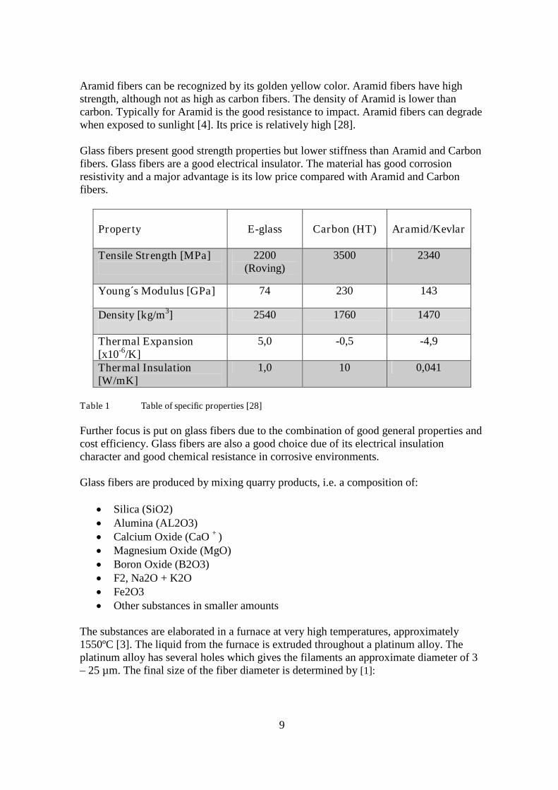
Glass fibers present good strength properties but lower stiffness than Aramid and Carbonfibers. Glass fibers are a good electrical insulator. The material has good corrosionresistivity and a major advantage is its low price compared with Aramid and Carbonfibers.
Property E-glass Carbon (HT) Aramid/Kevlar
Tensile Strength [MPa] 2200(Roving)
3500 2340
Young´s Modulus [GPa] 74 230 143
Density [kg/m3] 2540 1760 1470
Thermal Expansion[x10-6/K]
5,0 -0,5 -4,9
Thermal Insulation[W/mK]
1,0 10 0,041
Table 1 Table of specific properties [28]
Further focus is put on glass fibers due to the combination of good general properties andcost efficiency. Glass fibers are also a good choice due of its electrical insulationcharacter and good chemical resistance in corrosive environments.
Glass fibers are produced by mixing quarry products, i.e. a composition of:
Silica (SiO2) Alumina (AL2O3) Calcium Oxide (CaO + ) Magnesium Oxide (MgO) Boron Oxide (B2O3) F2, Na2O + K2O Fe2O3 Other substances in smaller amounts
The substances are elaborated in a furnace at very high temperatures, approximately1550ºC [3]. The liquid from the furnace is extruded throughout a platinum alloy. Theplatinum alloy has several holes which gives the filaments an approximate diameter of 3– 25 µm. The final size of the fiber diameter is determined by [1]:
10
hole size of the platinum alloy temperature and viscosity of the melt cooling rate drawing speed
The fibers are quenched after leaving the platinum alloy. Before the fibers are gatheredtogether they are sized in order to protect the fibers. The sizing can be designed fordifferent matrix types. By varying the proportions of raw materials, different types ofglass fibers can be produced, e.g. E, C, D, R, S, T or AR-glass.
E-glass (electrical) is the most common used fiber among composites [3]. E-glass hasgood tensile and compressive strength. The cost is relatively low compared to other glassfiber types. The impact resistance is however fairly poor.
C-glass (chemical) has the best resistance against chemical attacks of the different glassfiber types. Thus, C-glass is a good material that can be used in the outer layer ofapplications which are exposed to harsh environments.
D-Glass is characterized by excellent dielectric properties. It has low electrical losses andis consequently a good application for structures which needs to be permeable forelectromagnetic waves. D-glass fibers are used for applications such as electromagneticwindows, radomes and high performance printed circuit boards [3].
R, S or T-glass are the manufacturer’s trade names for equivalent fibers. These fibershave a higher modulus, higher tensile strength and higher interlaminar shear strengththan E-glass. However, these fibers come with a higher price.
AR-glass is a glass fiber that was especially developed for reinforcing cement. The highzirconium content gives good resistance to the alkaline compounds that is beinggenerated during drying of the cement. A typical application is building components.
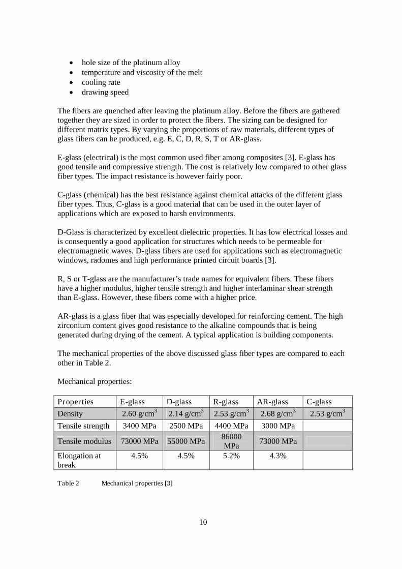
The mechanical properties of the above discussed glass fiber types are compared to eachother in Table 2.
Mechanical properties:
Properties E-glass D-glass R-glass AR-glass C-glass
Density 2.60 g/cm3 2.14 g/cm3 2.53 g/cm3 2.68 g/cm3 2.53 g/cm3
Tensile strength 3400 MPa 2500 MPa 4400 MPa 3000 MPa
Tensile modulus 73000 MPa 55000 MPa86000MPa
73000 MPa
Elongation atbreak
4.5% 4.5% 5.2% 4.3%
Table 2 Mechanical properties [3]
11
2.2 Matrix
The fibers of a fiber composite are combined with a matrix to form the compositematerial. The function of the matrix is to transfer loads to the reinforcement, i.e. thefibers. The matrix also holds the reinforcement in place and acts as a protection of thefibers from the surrounding environment, as fibers can be quite brittle.
Whereas polymers are the dominating matrix material in fiber composites, there are someother matrix that are used as well in composites, e.g. metals, carbon, ceramics andconcrete. Concrete as matrix are used in building structures where the reinforcement ismade of glass fiber and replaces steel. The concrete/glass combination gives a weightreducing effect on building structures. Carbon matrices are used in carbon-carboncomposites and are applied in high-temperature applications, e.g. rocket engines. For theutility pole construction further focus is set on polymer matrices.
2.2.1 Thermosets and thermoplastics
There are two major groups of polymers; Thermosets and Thermoplastics. The twogroups differ in their chemical structure. One of the most fundamental differences is themolecular structure, where thermoplastics consist of long molecules with only secondarybonding between them, e.g. van der Waals bondings. In contrary, thermosets formbesides secondary bondings also covalent bonds between the original molecules. Thesecovalent bonds are formed during the crosslinking process, when the thermoset resincures.
The highly crosslinked bonds in thermosets result in a three-dimensional network. Thestructures of thermosets result in properties such as:
excellent mechanical properties (high stiffness, hardness and strength) better resistance to solvents and heat.
However, thermosets matrices can be more brittle than thermoplastics.
Due to the differences in the molecule structure, thermoplastics can be melted;thermosets on the other hand cannot due to the covalent bonds. As a consequence, thepossibilities to recycle fiber composites differ between thermosets and thermoplastics.See section 9.1.
When choosing a matrix for an application one must also consider the matrixprocessability. In section 3 the production methods are described. Thermosets have anadvantage in processing due to their lower viscosity. Lower viscosity in the matriximproves the reinforcement impregnation. In Table 3 a comparison between thermosetmatrices and thermoplastics matrices is presented. In Table 3 “+” represents anadvantage.

12
Property Thermosets ThermoplasticsCost +Temperature tolerance +Stiffness +Strength +Toughness +Fatigue life +Creep +Chemical resistance +Viscosity +Recyclability +
Table 3 Comparison table Thermosets vs. Thermoplastics [1]
Based on the result of Table 3 one can see that for a utility pole application, thermosetsare preferred as matrix. Therefore, further focus presenting different matrix materials willbe on thermosets.
The most common thermosets used in today fiber reinforced composites construction are:
Unsaturated Polyester Vinylester Phenolics Epoxies
2.2.2 Unsaturated Polyester
Unsaturated Polyester resin (UP) is the most commonly used resin for the compositeindustry [6] and is sometimes referred as the workhorse of thermosets [1]. The UP comesin different types with different properties and is classified by its building blocks.
To construct an UP molecule, i.e. a basic building block, a special alcohol and a di-basicacid are put together which starts a reaction and creates the polyester and water as abyproduct [7]. By modifying the acids, alcohols and cross-linking monomers, and otheradditional products that are inserted in the polymer, different UP:s are produced.
The two most common UP:s that are used are orthophthalic polyester and isophthalicpolyester. The differences between these two polyesters are that the orthophthalicpolyester has lower cost but also has more modest mechanical properties than isophthalicpolyester. Isophthalic polyester on the other hand has better environmental and waterresistance properties than orthophthalic polyester [7].
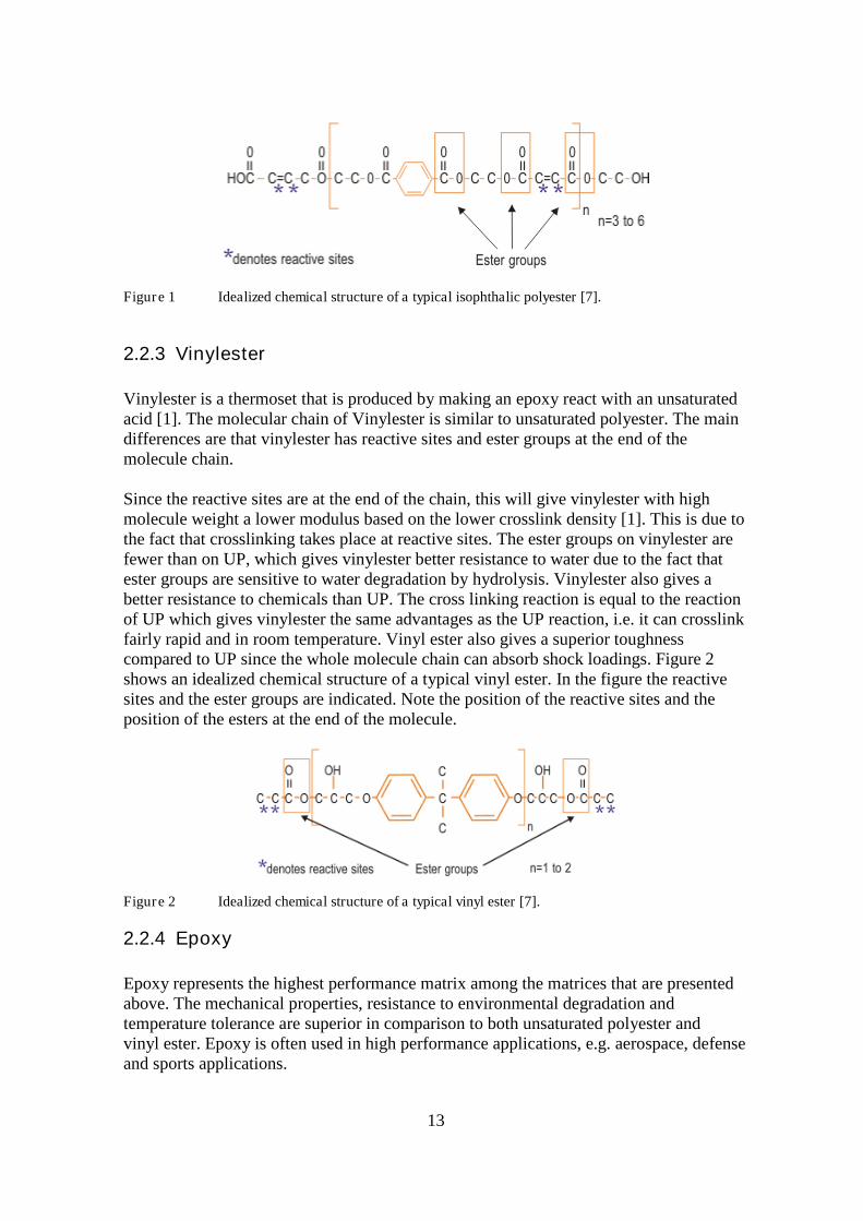
Figure 1 shows an idealized chemical structure of a typical isophthalic polyester. In thefigure, the reactive sites and the ester groups are indicated.
13
Figure 1 Idealized chemical structure of a typical isophthalic polyester [7].
2.2.3 Vinylester
Vinylester is a thermoset that is produced by making an epoxy react with an unsaturatedacid [1]. The molecular chain of Vinylester is similar to unsaturated polyester. The maindifferences are that vinylester has reactive sites and ester groups at the end of themolecule chain.
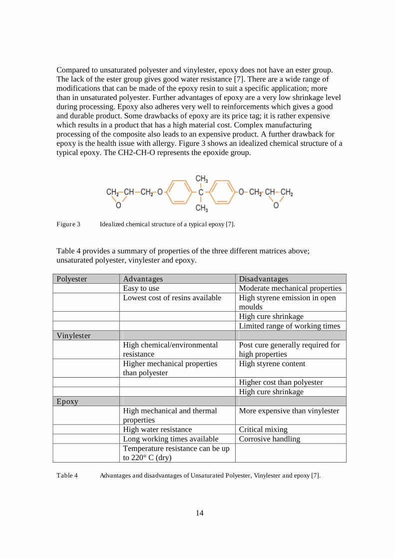
Since the reactive sites are at the end of the chain, this will give vinylester with highmolecule weight a lower modulus based on the lower crosslink density [1]. This is due tothe fact that crosslinking takes place at reactive sites. The ester groups on vinylester arefewer than on UP, which gives vinylester better resistance to water due to the fact thatester groups are sensitive to water degradation by hydrolysis. Vinylester also gives abetter resistance to chemicals than UP. The cross linking reaction is equal to the reactionof UP which gives vinylester the same advantages as the UP reaction, i.e. it can crosslinkfairly rapid and in room temperature. Vinyl ester also gives a superior toughnesscompared to UP since the whole molecule chain can absorb shock loadings. Figure 2shows an idealized chemical structure of a typical vinyl ester. In the figure the reactivesites and the ester groups are indicated. Note the position of the reactive sites and theposition of the esters at the end of the molecule.
Figure 2 Idealized chemical structure of a typical vinyl ester [7].
2.2.4 Epoxy
Epoxy represents the highest performance matrix among the matrices that are presentedabove. The mechanical properties, resistance to environmental degradation andtemperature tolerance are superior in comparison to both unsaturated polyester andvinyl ester. Epoxy is often used in high performance applications, e.g. aerospace, defenseand sports applications.
14
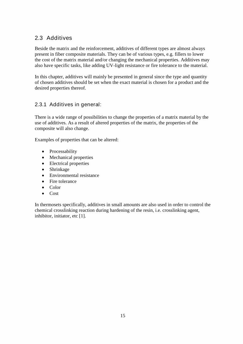
Compared to unsaturated polyester and vinylester, epoxy does not have an ester group.The lack of the ester group gives good water resistance [7]. There are a wide range ofmodifications that can be made of the epoxy resin to suit a specific application; morethan in unsaturated polyester. Further advantages of epoxy are a very low shrinkage levelduring processing. Epoxy also adheres very well to reinforcements which gives a goodand durable product. Some drawbacks of epoxy are its price tag; it is rather expensivewhich results in a product that has a high material cost. Complex manufacturingprocessing of the composite also leads to an expensive product. A further drawback forepoxy is the health issue with allergy. Figure 3 shows an idealized chemical structure of atypical epoxy. The CH2-CH-O represents the epoxide group.
Figure 3 Idealized chemical structure of a typical epoxy [7].
Table 4 provides a summary of properties of the three different matrices above;unsaturated polyester, vinylester and epoxy.
Polyester Advantages DisadvantagesEasy to use Moderate mechanical propertiesLowest cost of resins available High styrene emission in open
mouldsHigh cure shrinkageLimited range of working times
VinylesterHigh chemical/environmentalresistance
Post cure generally required forhigh properties
Higher mechanical propertiesthan polyester
High styrene content
Higher cost than polyesterHigh cure shrinkage
EpoxyHigh mechanical and thermalproperties
More expensive than vinylester
High water resistance Critical mixingLong working times available Corrosive handlingTemperature resistance can be upto 220° C (dry)
Table 4 Advantages and disadvantages of Unsaturated Polyester, Vinylester and epoxy [7].
15
2.3 Additives
Beside the matrix and the reinforcement, additives of different types are almost alwayspresent in fiber composite materials. They can be of various types, e.g. fillers to lowerthe cost of the matrix material and/or changing the mechanical properties. Additives mayalso have specific tasks, like adding UV-light resistance or fire tolerance to the material.
In this chapter, additives will mainly be presented in general since the type and quantityof chosen additives should be set when the exact material is chosen for a product and thedesired properties thereof.
2.3.1 Additives in general:
There is a wide range of possibilities to change the properties of a matrix material by theuse of additives. As a result of altered properties of the matrix, the properties of thecomposite will also change.
Examples of properties that can be altered:
Processability Mechanical properties Electrical properties Shrinkage Environmental resistance Fire tolerance Color Cost
In thermosets specifically, additives in small amounts are also used in order to control thechemical crosslinking reaction during hardening of the resin, i.e. crosslinking agent,inhibitor, initiator, etc [1].

16
2.3.2 Additives – for a utility pole composite
Decisions about what additives to use in the matrix material could preferably be done ina late stage in the design phase, since several aspects influence the choice of includingadditives. Such aspects are:
what composite material is to be used are there any mechanical properties that need to be altered is it desired to lower the cost of material by the use of inexpensive fillers, and if
so, what will be impact be on mechanical properties
Nevertheless, some additives will most likely be considered:
UV-absorbers:Also called Stabilizers. A UV-resistant additive. The impact of sunlight on mostpolymers may lead to discoloring and/or a more brittle material after exposure. Astabilizer can prevent such long-term effects by absorbing UV-light [1,29].
Colorants:An alternative to have an outer paint layer is to include small amounts of colorant in theresin. Such a choice eliminates the need for costly painting. Most colorants are in theform of pigments [1,29].
17
3 Composite Manufacturing Techniques
There are a number of manufacturing techniques used for fiber composites. Depending ofthe product, some techniques are better suited for the product than other. Price, shape andmaterial are some of the parameters that govern the choice of manufacturing technique.In this section, manufacturing techniques well suited for fiber composite utility poles areintroduced.
3.1 Filament Winding
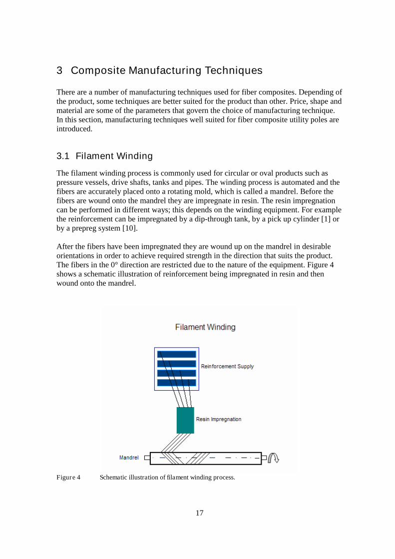
The filament winding process is commonly used for circular or oval products such aspressure vessels, drive shafts, tanks and pipes. The winding process is automated and thefibers are accurately placed onto a rotating mold, which is called a mandrel. Before thefibers are wound onto the mandrel they are impregnate in resin. The resin impregnationcan be performed in different ways; this depends on the winding equipment. For examplethe reinforcement can be impregnated by a dip-through tank, by a pick up cylinder [1] orby a prepreg system [10].
After the fibers have been impregnated they are wound up on the mandrel in desirableorientations in order to achieve required strength in the direction that suits the product.The fibers in the 0° direction are restricted due to the nature of the equipment. Figure 4shows a schematic illustration of reinforcement being impregnated in resin and thenwound onto the mandrel.
Figure 4 Schematic illustration of filament winding process.
18
After adequate layers have been applied to the mandrel, the processed part is left to cure.Depending on what matrix that is used the cure process can take place in either roomtemperature or if the matrix requires, in enhanced temperature using an oven. Anautoclave may be used to assist the cure process when required.
The filament winding offers a fast and automated process which lowers the labor cost. Awide selection of thermoset matrices can be used in the process, e.g. epoxy, polyester,vinylester and phenolics [10]. As reinforcement material a wide selection of strand canbe used e.g. glass fiber, carbon, Kevlar and etcetera.
Void fractions are relatively low with the filament winding process and the mechanicalproperties are good. The resin content can be controlled and the volume fraction of thereinforcement can be up to 70% [1]. The cost for large mandrels is however quite highand is therefore more suited for long product series. Another negative aspect is that thesurface finish has an unattractive look.
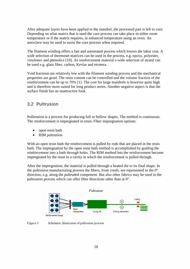
3.2 Pultrusion
Pulltrusion is a process for producing full or hollow shapes. The method is continuous.The reinforcement is impregnated in resin. Fiber impregnation options:
open resin bath RIM pultrusion
With an open resin bath the reinforcement is pulled by rods that are placed in the resinbath. The impregnation by the open resin bath method is accomplished by guiding thereinforcement into a bath through holes. The RIM method lets the reinforcement becomeimpregnated by the resin in a cavity in which the reinforcement is pulled through.
After the impregnation, the material is pulled through a heated die to its final shape. Inthe pultrusion manufacturing process the fibers, from creels, are represented in the 0°direction, e.g. along the pultruded component. But also other fabrics may be used in thepultrusion process which can offer fiber directions other than at 0°.
Figure 5 Schematic illustration of pultrusion process
19
The pultrusion process can offer products consisting of fiber materials and with a weightfraction from 30 to 70 percent, depending on shape, design and etcetera. Resins that canbe used generally in the process include epoxy, polyester, vinylester and phenolics. Alsosome thermoplastics can be used.
The main advantage with pultrusion is that the method can be very fast and thereforeeconomic. On the other hand, heat die costs can be high. The labor costs are low due tothe automated process. The properties can be very good since the fibers can be accuratelystraight and high fiber content is possible. A disadvantage with pultrusion is thelimitation to near constant cross sections, which leads to restricted possibility to process aconic shape. Another disadvantage with pultrusion is when it is processed with openresin bath due to the volatile emissions from the resin.
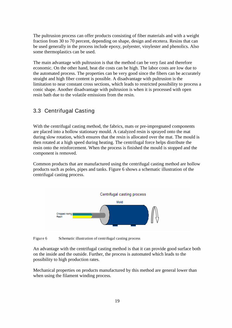
3.3 Centrifugal Casting
With the centrifugal casting method, the fabrics, mats or pre-impregnated componentsare placed into a hollow stationary mould. A catalyzed resin is sprayed onto the matduring slow rotation, which ensures that the resin is allocated over the mat. The mould isthen rotated at a high speed during heating. The centrifugal force helps distribute theresin onto the reinforcement. When the process is finished the mould is stopped and thecomponent is removed.
Common products that are manufactured using the centrifugal casting method are hollowproducts such as poles, pipes and tanks. Figure 6 shows a schematic illustration of thecentrifugal casting process.
Figure 6 Schematic illustration of centrifugal casting process
An advantage with the centrifugal casting method is that it can provide good surface bothon the inside and the outside. Further, the process is automated which leads to thepossibility to high production rates.
Mechanical properties on products manufactured by this method are general lower thanwhen using the filament winding process.

20
4 Attachments
No matter in what material the utility pole is designed for, the pole needs to have detailsattached to it such as:
Climbing aids to make it possible for maintenance personnel to climb the pole Crossarms Stays, if they are not fastened in the crossarm Ground attachments
For structures made of wood or metal, there are widely established methods to joinattachments to the structure. Joining attachments to a structure of fiber composite is notvery different, but there are a few things to keep in mind, partly due to the materialhaving non-homogenous properties.
The two most common techniques in joining different part are mechanical joining andadhesive joining. Both techniques can be used for composite parts and they both haveadvantages and disadvantages.
4.1 Adhesive joining
Adhesive joining requires an overlap area in which the two different parts adhere. Thisarea must be sufficiently large in order to carry the transferred load. It is also important toanalyze how the forces to carry are directed. Preferred mode of load transfer is shear [1].
Figure 7 Schematic illustration of shear stress
As seen in Figure 7, the highest shear stresses occur at the ends of the joint. Therefore, afailure is likely to be initiated at the ends of the joint.
A very disadvantageous load case is when there is a load perpendicular to the joint, alsoknown as ”peel force”. This type of loading may lead to delamination of the joint. Therisk of delamination through peel forces can be reduced by carefully designing joints.
Figure 8 Schematic illustration of delaminate lamina
21
The most commonly used adhesives are based on epoxies. But also thermoplastics areused as adhesives for composites. Thermoplastics are hot melted and applied. When theycool, they re-harden. A disadvantage of epoxies is their weak peeling strength. Epoxiesare therefore often modified with elastomers in order to improve fracture toughness andpeel strength [14].
Before joining parts adhesively, proper surface preparations are important. The surfaceshave to be cleaned accurately and all kind of contaminations have to be removed. Thesurfaces then are abraded in order to get a rough surface. This increases the active surfacearea as well as the surface energy in order to improve the bonding [14].
A disadvantage with adhesive joining compared with mechanical joining is that the part’ssurfaces must match each other quite well.
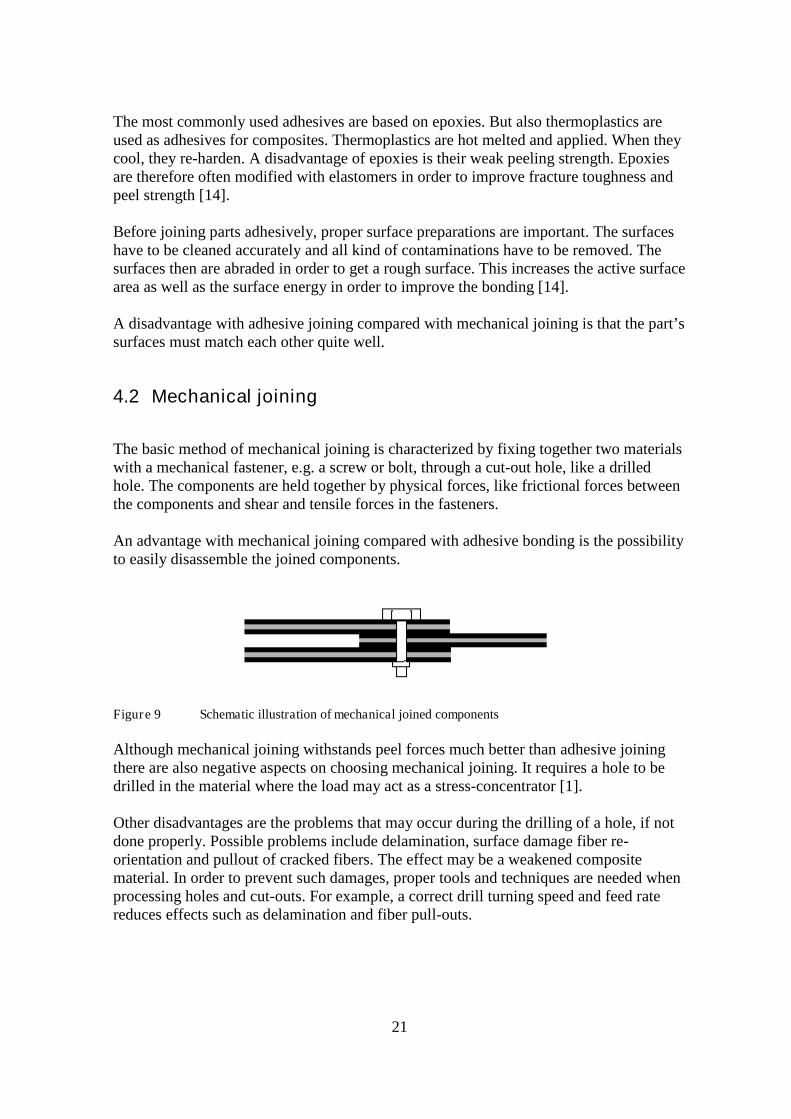
4.2 Mechanical joining
The basic method of mechanical joining is characterized by fixing together two materialswith a mechanical fastener, e.g. a screw or bolt, through a cut-out hole, like a drilledhole. The components are held together by physical forces, like frictional forces betweenthe components and shear and tensile forces in the fasteners.
An advantage with mechanical joining compared with adhesive bonding is the possibilityto easily disassemble the joined components.
Figure 9 Schematic illustration of mechanical joined components
Although mechanical joining withstands peel forces much better than adhesive joiningthere are also negative aspects on choosing mechanical joining. It requires a hole to bedrilled in the material where the load may act as a stress-concentrator [1].
Other disadvantages are the problems that may occur during the drilling of a hole, if notdone properly. Possible problems include delamination, surface damage fiber re-orientation and pullout of cracked fibers. The effect may be a weakened compositematerial. In order to prevent such damages, proper tools and techniques are needed whenprocessing holes and cut-outs. For example, a correct drill turning speed and feed ratereduces effects such as delamination and fiber pull-outs.
22
5 Composite Utility Pole Manufacturers
5.1 Existing manufacturers
The found suppliers of composite utility poles are mostly present in North America. Eventhough the global market for replacement and new poles is huge, the market break-through so far has mainly been taken place in North America.
Outside North America a new supplier in Brazil has emerged, Petrofisa. At the annualJEC Composites show in Paris, Apr 2007, the fiber glass manufacturer Owens-Corninghighlighted their cooperation with Petrofisa, a local Brazilian fiber composite companywhich will produce composite utility poles for the Brazilian electrical power distributionsector [30]. This company will not be presented further in this text due to the lack ofmaterial in English.
In Europe, no manufactures presently producing utility poles in fiber composite materialhave been found.
5.1.1 Shakespeare
www.skp-cs.com
Shakespeare Composite Structures, based in South Carolina, U.S.A, has been filamentwinding composite utility poles since 1992 [31].
The matrix consists of a polyester thermoset. For UV-resistance, the resin contains UV-inhibitors. A polyurethane coating is present in order to further enhance the UV-protection.
Based upon experience and accelerated testing, Shakespeare claims a minimum life of 40years, after which the product may show visual effects of ageing but retain a very highpercentage of its strength. The company also claims composite poles will outlast wood,aluminum, steel and concrete pole under the same climatic conditions.
A variety of colors can be achieved by pigmentation of the resin during manufacturing.The polyurethane coating, containing UV-inhibitors, prevents fading over the years.
The company uses filament winding as manufacturing method. Axial strength may posea challenge for filament winding due to the difficulties of positioning fibers axially. Withtechnology advances, Shakespeare has however succeeded in winding fibers at lowangles.
Utility poles are available up to 75ft (22,8m) height.
23
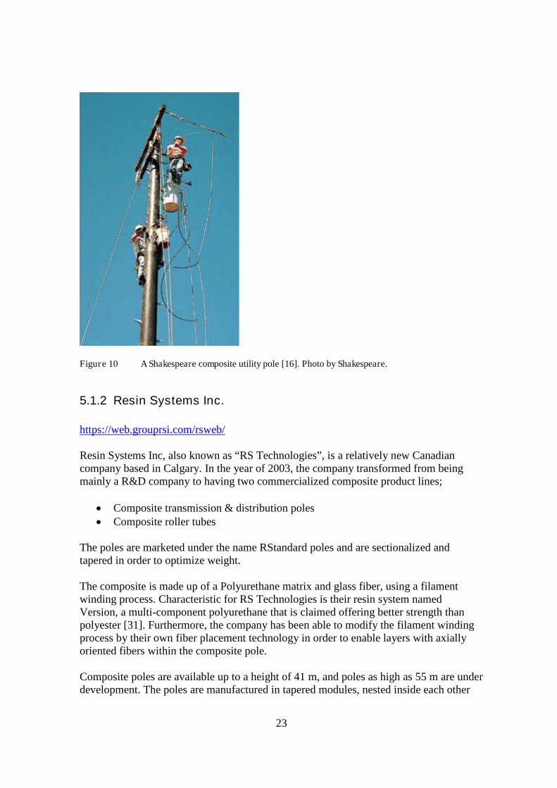
Figure 10 A Shakespeare composite utility pole [16]. Photo by Shakespeare.
5.1.2 Resin Systems Inc.
https://web.grouprsi.com/rsweb/
Resin Systems Inc, also known as “RS Technologies”, is a relatively new Canadiancompany based in Calgary. In the year of 2003, the company transformed from beingmainly a R&D company to having two commercialized composite product lines;
Composite transmission & distribution poles Composite roller tubes
The poles are marketed under the name RStandard poles and are sectionalized andtapered in order to optimize weight.
The composite is made up of a Polyurethane matrix and glass fiber, using a filamentwinding process. Characteristic for RS Technologies is their resin system namedVersion, a multi-component polyurethane that is claimed offering better strength thanpolyester [31]. Furthermore, the company has been able to modify the filament windingprocess by their own fiber placement technology in order to enable layers with axiallyoriented fibers within the composite pole.
Composite poles are available up to a height of 41 m, and poles as high as 55 m are underdevelopment. The poles are manufactured in tapered modules, nested inside each other

24
for easy transportation and storage. A module is never longer than 11m duringtransportation even though the full length is up to 41 m. Thus the poles are easy totransport to difficult locations.
In November 2005, an initial shipment of poles was shipped to a non-disclosed Europeanenergy producer for testing. The initial order was however not fulfilled and since March2007, Resin Systems Inc. has chosen a strategy to focus on the North American domesticmarket for utility poles [17].
5.1.3 Powertrusion
www.powertrusion.com
Powertrusion is a company based in Tucson, Arizona, USA, which started production ofcomposite utility poles in the late 90’s.
The main product of the company is a composite pultruded power distribution pole. Thedesign of the pultruded pole is non-tapered, with a fixed diameter throughout the pole’slength. Even though the non-tapered design might offer a higher weight than taperedpoles, Powertrusion nevertheless claims the weight of their composite pole is only about40% compared with a standard wooden pole of the same class.
The material used today for the company’s composite poles consists of glass fiber with apolyurethane resin from Reichhold [15], an American global resin supplier withproduction facilities present in Europe as well as other continents.
With the pultrusion manufacturing technique, the poles of Powertrusion contain glassfibers that are pre-stressed and placed longitudinal, as well as woven fibers for hoopstrength. [Hoop strength: The ability of a tube to withstand bending and crushingforces]. The manufacturing technique delivers a standard deviation in strength of 1,9%.
Powertrusion poles are available up to 60 ft (17m). The poles can be pre-drilled with e.g.steps or other mounting hardware according to the requirements of a customer.
The UV-protection consists of three levels:
1. UV-inhibitors throughout the matrix resin2. A UV-stable pigment additive in the matrix resin to provide color.3. A resin-rich surface veil for giving additional protection. The surface veil is not a
load-carrying part of the structure.
Powertrusion claims an expected service life of their utility poles up to 80 years, onceinstalled. During a major firestorm in the year 2003 outside San Diego, California, aPowertrusion pole (which a local energy company was testing) withstood the fire,whereas approximately 3000 ordinary utility poles were consumed by the fires [31,32].
25
5.1.4 Strongwell
www.strongwell.com
Strongwell has been pultruding fiber reinforced polymers composite products since theyear 1956. The company is active in many different markets, including utility poles. Itsheadquarters as well as the main manufacturing site is located in the State of Virginia,U.S.A.
The market name of Strongwell’s composite utility pole is SE28; a tapered pole availablein lengths up to 80ft (24m), weighing 612kg. Strongwell uses pultrusion asmanufacturing technique. The composite contains glass fiber as reinforcement and amatrix made of vinylester resin [31].
In contrast to other composite utility pole producers, Strongwell’s pole is not circular butshaped as a 12-sided polygon. Holes can be pre-drilled but the pole is also drillable infield. In terms of engineering, the poles are intended to be a direct replacement forwooden poles.
The UV-protection is based upon:
1. UV-inhibiting binders inside the matrix2. Surface veils3. Paint coating
According to Strongwell, the poles can last indefinitely. After 25-30 years of service, are-application of the UV-inhibiting paint coating may be required as the only significantmaintenance needed.

26
Company Shakespeare Composites Resin Systems Inc
Location Newberry, South Carolina,U.S.A
Calgary, Canada
Website www.skp-cs.com www.grouprsi.com
Type of Fiber Glass Fiber Glass Fiber
Composite Matrix Polyester thermoset Polyurethane thermoset
Production method Filament winding Filament winding
Maximum height 21 m 41 m
Power Pole Experience 1993 2003
UV resistance - UV-inhibitors in resin- Polyurethane coating
- "Built-in UV-protection"- Details not known
Table 5 Composite pole manufacturers
Company Powertrusion International Strongwell
Location Tucson, Arizona, U.S.A Bristol, Virginia, U.S.A
Website www.powertrusion.com www.strongwell.com
Type of Fiber Glass Fiber Glass Fiber
Composite Matrix Polyurethane thermoset Vinylester thermoset
Production method Pultrusion Pultrusion
Maximum height 17 m 24 m
Power Pole Experience Since late 90's
UV resistance - UV-inhibitors in resin- UV-stable pigment- Resin-rich surface veil
- UV-inhibitors in resin- Surface veil- Paint coating
Table 6 Composite pole manufacturers

27
5.2 Future manufactures
Most of the found manufacturers of composite utility poles are present in North America.A manufacturer in Scandinavia could be preferable by some reasons, e.g. easier and/orcheaper shipping, as well as time to delivery aspects.
The focus has therefore been to look at companies that might be possible futurecandidates for the manufacturing of composite utility poles. Among those are thecompanies Exel Oy in Finland and Fiberline in Denmark.
5.2.1 Exel
http://www.exel.net
Contact: Jan Lord, SalesEmail: [email protected]
Exel is a well established company which manufactures composite profiles. Thecompany consists of the parent company Exel Oyj in Finland and ten subsidiaries. Theirproduction plants are located in:
Finland Germany Belgium Austria Australia UK China
Exel utilize production techniques such as:
pultrusion pullwinding co-winding continuous lamination pre-preg manufacturing
The different techniques are used in many of Exel’s products, ranging from sportsapplications in Exel Sports to tubes and antenna radomes in Exel Composite, IndustryDivision.

28
Two of the production techniques that Exel offers are pultrusion and pullwinding, seeFigure 13. Both pultrusion and pullwinding are suitable methods for manufacturingutility poles. Pullwinding is a method that combines pultrusion and filament winding.The method can offer inclusion of longitudinal reinforcement with helically-woundlayers. According to Exel, the crosswise reinforcement performed by the pullwindingoffers better performance than reinforcements in mats and fabrics that offer the crosswisereinforcement.
1. Reinforcement2. Winding unit3. Pultrusion unit4. Pulling unit5. Sawing unit
Figure 11 The Pullwinding of process of Exel [24]. Photo by Exel.
For a utility pole Exel can provide different matrix systems, such as epoxy, vinylesterand unsaturated polyester. Different fibers such as glass fiber, Kevlar and carbon fiberare optional. The company can offer both a tapered shaped pole and continuous crosssection poles. Exel has given a positive response on the question if they would be able tomanufacture utility poles.
29
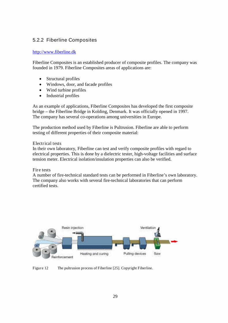
5.2.2 Fiberline Composites
http://www.fiberline.dk
Fiberline Composites is an established producer of composite profiles. The company wasfounded in 1979. Fiberline Composites areas of applications are:
Structural profiles Windows, door, and facade profiles Wind turbine profiles Industrial profiles
As an example of applications, Fiberline Composites has developed the first compositebridge – the Fiberline Bridge in Kolding, Denmark. It was officially opened in 1997.The company has several co-operations among universities in Europe.
The production method used by Fiberline is Pultrusion. Fiberline are able to performtesting of different properties of their composite material:
Electrical testsIn their own laboratory, Fiberline can test and verify composite profiles with regard toelectrical properties. This is done by a dielectric tester, high-voltage facilities and surfacetension meter. Electrical isolation/insulation properties can also be verified.
Fire testsA number of fire-technical standard tests can be performed in Fiberline’s own laboratory.The company also works with several fire-technical laboratories that can performcertified tests.
Figure 12 The pultrusion process of Fiberline [25]. Copyright Fiberline.
30
6 Maintenance and inspections techniques
6.1 Maintenance
Fiber composite utility poles in general require very little maintenance. Manufacturersclaim their products are maintenance-free.
Due to the nature and properties of the constituent materials in a fiber composite utilitypole; glass fibers and a thermoset polymer matrix; the product is practically immune to:
Corrosion Biological attacks, e.g. fungus Animals and birds, e.g. woodpeckers or insects
Still, impacts of different kinds may damage a pole, e.g.
Forest fires Vehicle impacts when pole positioned close to a road Falling ice from power lines during harsh weather
Damage may result in a fiber layer delamination which can affect the mechanicalproperties and the structural integrity of the composite pole, depending on the damageextent. Depending on the pole construction, a breach in the outer material layer should berepaired. This is true for poles that have an outer layer specially designed for UV-protection.
Composite poles that have a paint layer as a part of the UV-protection (e.g. Strongwell)might require a re-application of UV-inhibiting after 25-30 years.
No other treatment in general should be necessary during the entire life of a compositeutility pole.
6.2 Inspection techniques
Destructive inspection techniques will for obvious reasons not be treated here. In order todiagnose damages in composite structures in general, there are several methods for non-destructive inspection (NDI).
Traditional methods might require the product to be taken out of service for inspectionand are labor intensive. For a utility pole in an electrical power infrastructure, this is notan option since it would require the power line to be temporarily shut down and possiblythe utility pole to be dismounted. Examples of traditional methods are X-ray inspectionsand ultrasonic inspections [1].

31
In case a composite utility pole needs to be inspected, e.g. due to a suspected damage, theinspection method should preferably be possible to conduct with the power line still inservice – at least at damages in the lower part of the pole. Furthermore, any inspectionequipment should preferably be reasonably practical to transport or carry to remote loca-tion deep into the nature. Two methods will be presented below which complements eachother; a vibrational inspection commonly called the Tap Test and visual inspections [1].
6.2.1 Tap test
The Tap test is a vibrational inspection method which is widely used in many fibercomposite applications, from boat building to aerospace applications. Sometimes the taptest is also referred to as the Coin Tap Technique.
By tapping on the material with a metal object, e.g. a coin, a sound is emitted. The pitchof the generated sound is normally of a certain frequency as the material vibrates due tothe impact causing a mechanical excitation. In case of an anomaly in the material belowthe surface, the pitch of the sound will change. The person performing the test gets aclear notification. For example, a sub-surface local delamination of fiber layers maygenerate a low-pitch sound when tapping with a coin on that local area, in contrast to ahigh-pitch sound heard on the healthy areas.
In practice, the tapping needs to be done just on the faulty spot in order to discover it bythe change in pitch of sound. This fact limits the method somewhat as it would be quitetime-consuming to perform the tapping over a bigger area. Rather, the tap test is suitablewhenever a local damage is suspected but not confirmed. For example, if the outer shellof the composite utility pole is damaged, the tap test can reveal whether or not thestructural integrity is intact in the fiber layers below the surface.
32
6.2.2 Visual Inspections
Visual inspection is a frequently used inspection method for fiber composite structures.The method should not be underestimated as a method for inspecting components fordefects and damages. For example, the method is used within the aerospace industry forchecking airplanes.
Due to its nature, a visual inspection can only reveal damages that appear on the surfaceof the inspected structure. This can be seen as a drawback for the method.
For a utility pole, the visual inspection technique is a good method to identify damageson the surface of the structure, or the paint layer if there is such a layer present.
6.2.3 A combined inspection
Preferably, the visual inspection technique can be combined with the Tap test.First, determine if any damage is present on a utility pole by inspecting it visually.In case there are any visual damage to the paint layer or surface of the pole structure,proceed by performing a Tap Test on the damaged area. Compare the pitch of sound withnon-damaged areas.
In case there is no difference in sound pitch, the structural integrity can be deemed intactand no repair other than some fresh paint might be necessary.
33
7 Design of Composite Utility poles
7.1 Pole dimensioning - Evaluated material thickness
In this section of the report, Design of Composite Utility poles, the material thickness of autility pole is evaluated. These calculations can be seen as an example of one method forhow to calculate a necessary material thickness for a composite utility pole. Theprerequisites for these calculations are:
Fiber material is glass fiber. See section 2.1, Fibers. This is the most realistic choice, andthe composite pole manufacturers of today all use glass fiber.Loads are given by Svenska Kraftnät.Allowed deflections are given by Svenska Kraftnät.The calculations are based on a 25 meter long pole with a uniform cross-section.
The estimated material thickness has been calculated by looking at the different loads(horizontal and vertical) separately only. This is the method used today in Sweden forwooden poles. The reason this method has been used is to facilitate a possible compari-son between composite poles and wooden poles. However, within a development forcomposite poles for a power line, it is recommended that both horizontal and verticalloads in combination are being considered since this will represent the actual load casemore accurately.
7.2 Determination of Elastic modulus
To predict and estimate the elastic modulus for a fiber composite the Rule of Mixtures(ROM) is used. Since the composite is a combination of both fibers and matrix the modu-lus of elasticity of the composite is a result of the contribution from both materials, i.e.the selected fiber and matrix. By multiplying Young’s modulus with the volume fractionof the fibers and the quantity of the total e.g. fibers or matrix, see Eq. 1, that are placed inthe principal direction the modulus is, here in 1-direction, estimated according to:
mmmfff EVEVE 1 (1)
where
1E Material’s elastic modulus in 1-direction (along the fibers)
f Alignment amount of fiber content in the 1- direction.
fV Fiber volume fraction
fE Fibers’ elastic modulus
m Amount of matrix content in the 1-direction.
mV Matrix volume fraction
mE Matrix’s elastic modulus
34
Equation 1 shows that depending on the following choices; what constituent materialsthat are chosen for the composite, the final volume fraction of those materials, and thefiber directions, the theoretical Young’s modulus will have an approximately value ofapproximately 20 GPa to 35 GPa. The maximum value should however be seen as a highvalue where most fibers are presented in the 1-direction.
7.3 Classic Beam Theory
7.3.1 Euler buckling
The vertical load on the pole is presented in Table 8. To evaluate an approximatematerial thickness of the pole, as determined by the requirements due to the vertical load,Euler’s buckling criteria is used.
Depending on how the pole is supported different Euler buckling modes can be used, i.e.Euler buckling mode 1-4. In order to calculate the material thickness in this work, focushas been put mainly on Euler’s first buckling mode.
If the pole is not supported by a stay the poles end conditions for the pole is fixed-free,whereas the Euler buckling criteria fixed-free condition is used, see Equation 2.
Euler’s fixed-free end condition:
2
2
4 L
IEPk
(2)
where
kP Vertical loadE Material’s elastic modulus in
L Pole lengthI Moment of inertia
35
7.3.2 Beam bending
In order to estimate the needed material thickness for the horizontal forces see Table 8.The Equation for elementary case beam bending has been used.
Beam bending, elementary case:
IE
LP
3
3
(3)
where
DeflectionP
Horizontal loadL Pole lengthE Material’s elastic modulus
I Moment of inertia
Moment of inertia for a hollow, circular pipe is given by:
44
64iy ddI
(4)
where
I Moment of inertia for a circular cross section
ydOuter diameter
id Inner diameter
7.4 Load and load cases
The loads and load cases in Table 7 are given from Svenska Kraftnät. T, V and L denotestransversal, vertical and longitudinal load and these loads are distributed on two poles.The load cases 1, 2a, 3 and 5a represent different load cases as follows:
load case 1 represent high wind and no ice on the power lines load case 2a represent no wind and ice on the power lines load case 3 represent high wind and ice on the power lines load case 5a represent security loads

36
Load casesLoad in kN 1 2a 3 5a 5a 5a
T1 3,66 0 7,05 0 0 0
V1 9,42 21,96 20,82 21,96 21,96 21,96
L1 0 0 0 22,29 0 0
T2 3,66 0 7,05 0 0 0
V2 9,42 21,96 20,82 21,96 21,96 21,96
L2 0 0 0 0 22,29 0
T3 3,66 0 7,05 0 0 0
V3 9,42 21,96 20,82 21,96 21,96 21,96
L3 0 0 0 0 0 0
T4 1,45 0 4,84 0 0 0
V4 2,29 10,44 9,19 10,44 10,44 10,44
L4 0 0 0 0 0 30,38
T5 1,45 0 4,84 0 0 0
V5 3,29 10,44 9,19 10,44 10,44 10,44
L5 0 0 0 0 0 0
Table 7 Load cases given from Svenska Kraftnät
The loads in Table 7 are distributed on two poles that support the power lines. This givesa load distribution on the two poles according to:
Pole number 1 2
Transverse load T: T1+ T4+ 0.5T2 T3+ T5+ 0.5T2
Vertical load V: V1+ V4+ 0.5 V2 V3+ V5+ 0.5 V2
Longitudinal load L: L1+ L4+ 0.5 L2 L3+ L5+ 0.5 L2
37
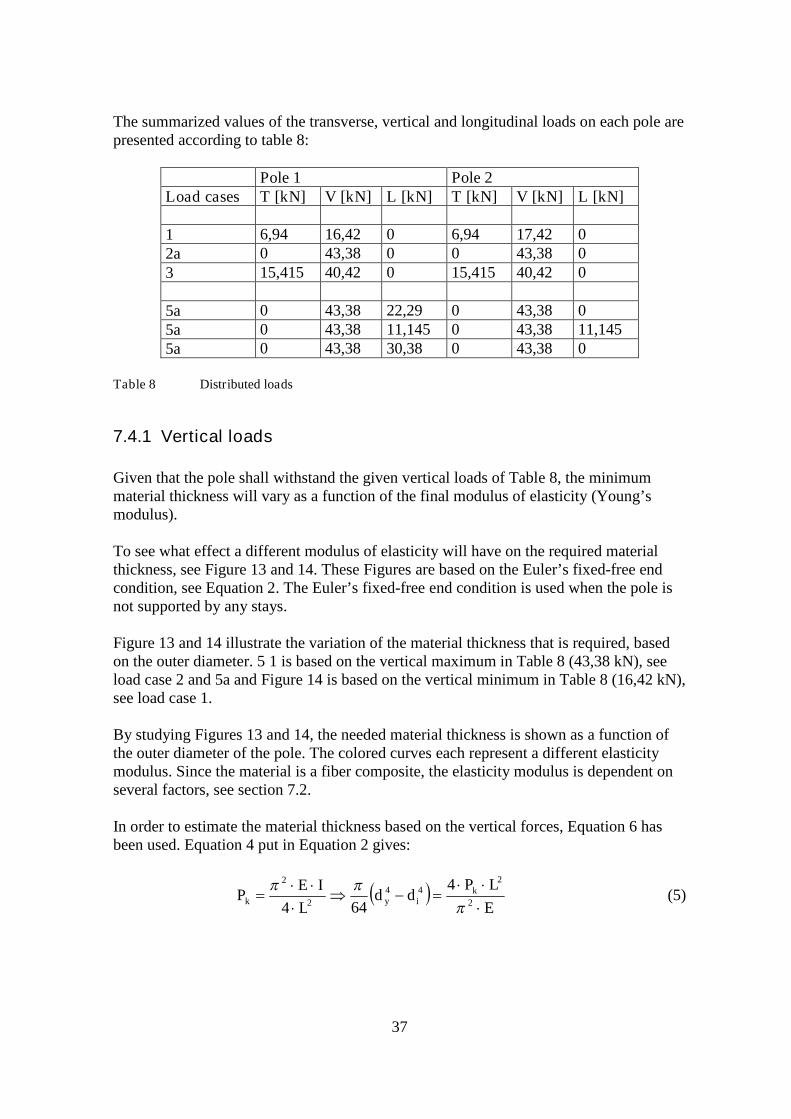
The summarized values of the transverse, vertical and longitudinal loads on each pole arepresented according to table 8:
Pole 1 Pole 2Load cases T [kN] V [kN] L [kN] T [kN] V [kN] L [kN]
1 6,94 16,42 0 6,94 17,42 02a 0 43,38 0 0 43,38 03 15,415 40,42 0 15,415 40,42 0
5a 0 43,38 22,29 0 43,38 05a 0 43,38 11,145 0 43,38 11,1455a 0 43,38 30,38 0 43,38 0
Table 8 Distributed loads
7.4.1 Vertical loads
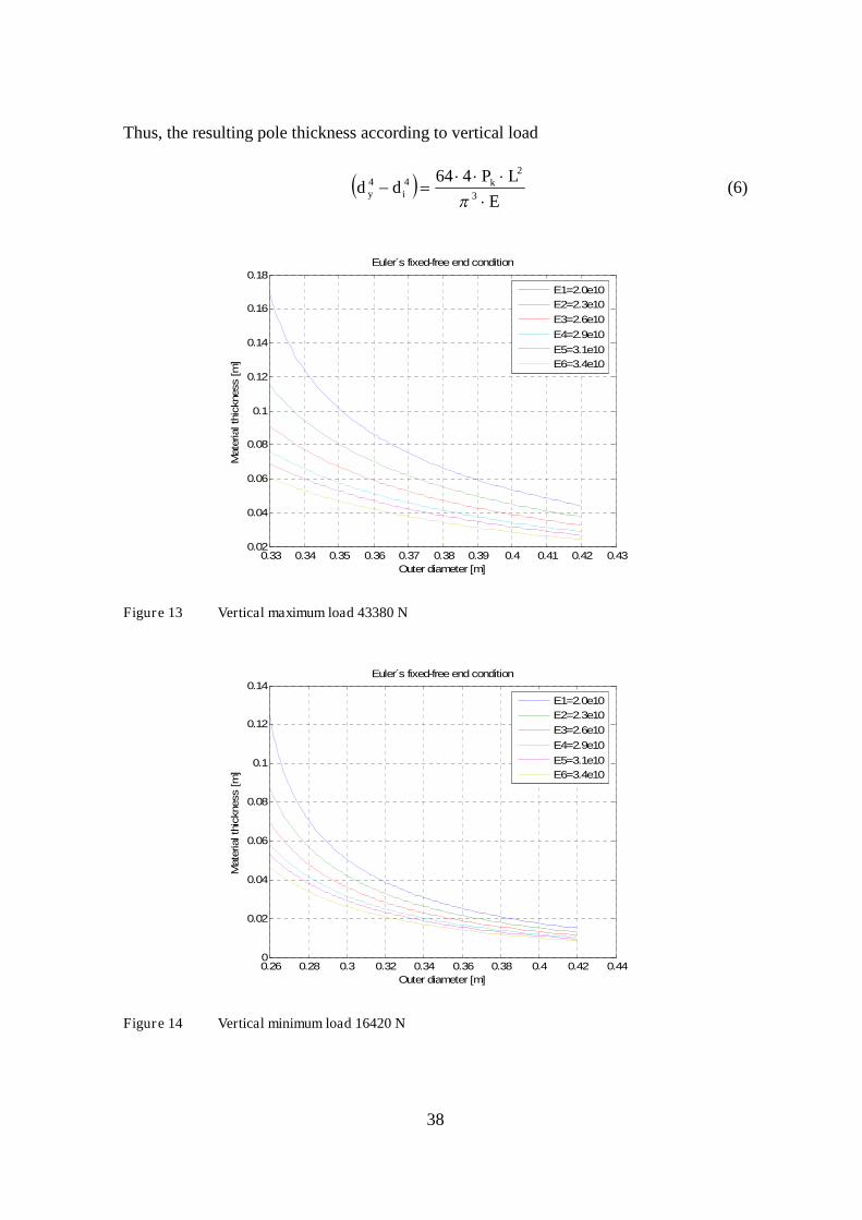
Given that the pole shall withstand the given vertical loads of Table 8, the minimummaterial thickness will vary as a function of the final modulus of elasticity (Young’smodulus).
To see what effect a different modulus of elasticity will have on the required materialthickness, see Figure 13 and 14. These Figures are based on the Euler’s fixed-free endcondition, see Equation 2. The Euler’s fixed-free end condition is used when the pole isnot supported by any stays.
Figure 13 and 14 illustrate the variation of the material thickness that is required, basedon the outer diameter. 5 1 is based on the vertical maximum in Table 8 (43,38 kN), seeload case 2 and 5a and Figure 14 is based on the vertical minimum in Table 8 (16,42 kN),see load case 1.
By studying Figures 13 and 14, the needed material thickness is shown as a function ofthe outer diameter of the pole. The colored curves each represent a different elasticitymodulus. Since the material is a fiber composite, the elasticity modulus is dependent onseveral factors, see section 7.2.
In order to estimate the material thickness based on the vertical forces, Equation 6 hasbeen used. Equation 4 put in Equation 2 gives:
E
LPdd
L
IEP k
iyk
2
244
2
2 4
644
(5)
38
Thus, the resulting pole thickness according to vertical load
E
LPdd k
iy
3
244 464
(6)
0.33 0.34 0.35 0.36 0.37 0.38 0.39 0.4 0.41 0.42 0.430.02
0.04
0.06
0.08
0.1
0.12
0.14
0.16
0.18
Outer diameter [m]
Mate
rialth
ickness
[m]
Euler s fixed-free end condition
E1=2.0e10
E2=2.3e10
E3=2.6e10
E4=2.9e10
E5=3.1e10
E6=3.4e10
Figure 13 Vertical maximum load 43380 N
0.26 0.28 0.3 0.32 0.34 0.36 0.38 0.4 0.42 0.440
0.02
0.04
0.06
0.08
0.1
0.12
0.14
Outer diameter [m]
Mate
rialth
ickness
[m]
Euler s fixed-free end condition
E1=2.0e10
E2=2.3e10
E3=2.6e10
E4=2.9e10
E5=3.1e10
E6=3.4e10
Figure 14 Vertical minimum load 16420 N
39
When dimensioning the structure, mainly three factors can be varied:
Elasticity modulus of the material Outer diameter Material thickness
If the dimensioning is based upon the maximum load case, a high elasticity modulusshould be chosen. If the dimensioning is based upon the minimum load case, a lowerelasticity modulus can be chosen. However, the outer diameter should not be too narrowif a low elasticity modulus is chosen.
A comparison with a solid wooden pole, given the same loads and using the SIS valueEwood = 10 GPa [33], will result in the following diameter of the solid wooden pole:
Maximum load case: diameter = 0,39 m.Minimum load case: diameter = 0,30 m.
7.4.2 Transverse and longitudinal loads
In order to estimate the material thickness based on the transversal and longitudinalforces, Equation 8 has been used. Equation 4 put in 3 gives
E
LPdd
IE
LPiy
3643
344
3
(7)
Thus, the resulting pole thickness according to beam bending
E
LPdd iy
3
64 344 (8)
where:
kP Transverse/Longitudinal load
E Elastic modulusL Pole length Deflection
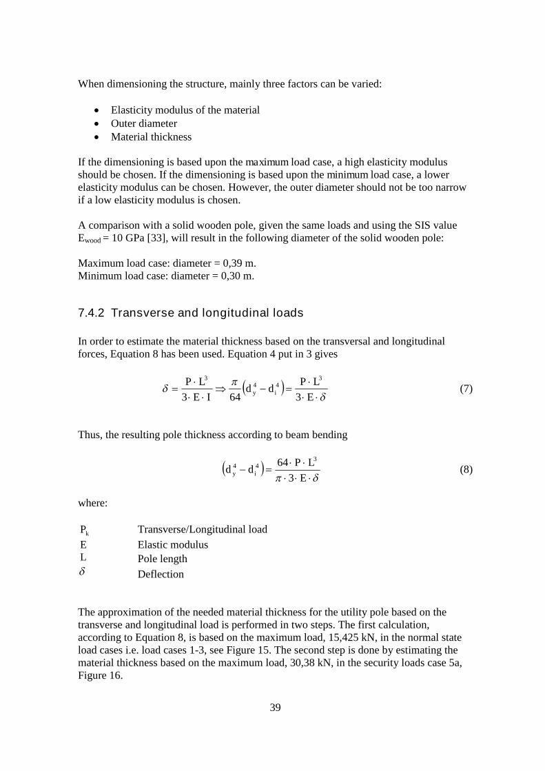
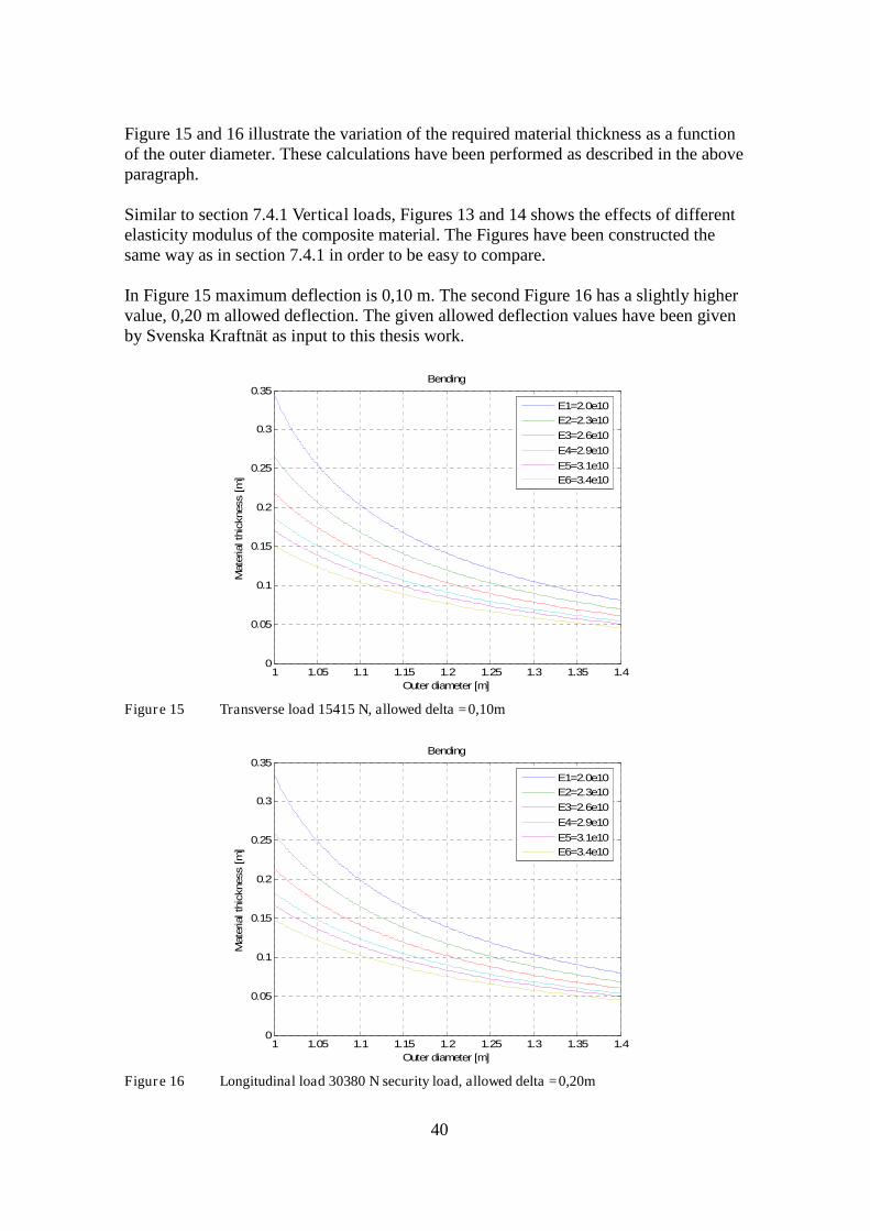
The approximation of the needed material thickness for the utility pole based on thetransverse and longitudinal load is performed in two steps. The first calculation,according to Equation 8, is based on the maximum load, 15,425 kN, in the normal stateload cases i.e. load cases 1-3, see Figure 15. The second step is done by estimating thematerial thickness based on the maximum load, 30,38 kN, in the security loads case 5a,Figure 16.
40
Figure 15 and 16 illustrate the variation of the required material thickness as a functionof the outer diameter. These calculations have been performed as described in the aboveparagraph.
Similar to section 7.4.1 Vertical loads, Figures 13 and 14 shows the effects of differentelasticity modulus of the composite material. The Figures have been constructed thesame way as in section 7.4.1 in order to be easy to compare.
In Figure 15 maximum deflection is 0,10 m. The second Figure 16 has a slightly highervalue, 0,20 m allowed deflection. The given allowed deflection values have been givenby Svenska Kraftnät as input to this thesis work.
1 1.05 1.1 1.15 1.2 1.25 1.3 1.35 1.40
0.05
0.1
0.15
0.2
0.25
0.3
0.35
Outer diameter [m]
Mate
rialth
ickness
[m]
Bending
E1=2.0e10
E2=2.3e10
E3=2.6e10
E4=2.9e10
E5=3.1e10
E6=3.4e10
Figure 15 Transverse load 15415 N, allowed delta =0,10m
1 1.05 1.1 1.15 1.2 1.25 1.3 1.35 1.40
0.05
0.1
0.15
0.2
0.25
0.3
0.35
Outer diameter [m]
Mate
rialth
ickness
[m]
Bending
E1=2.0e10
E2=2.3e10
E3=2.6e10
E4=2.9e10
E5=3.1e10
E6=3.4e10
Figure 16 Longitudinal load 30380 N security load, allowed delta =0,20m
41
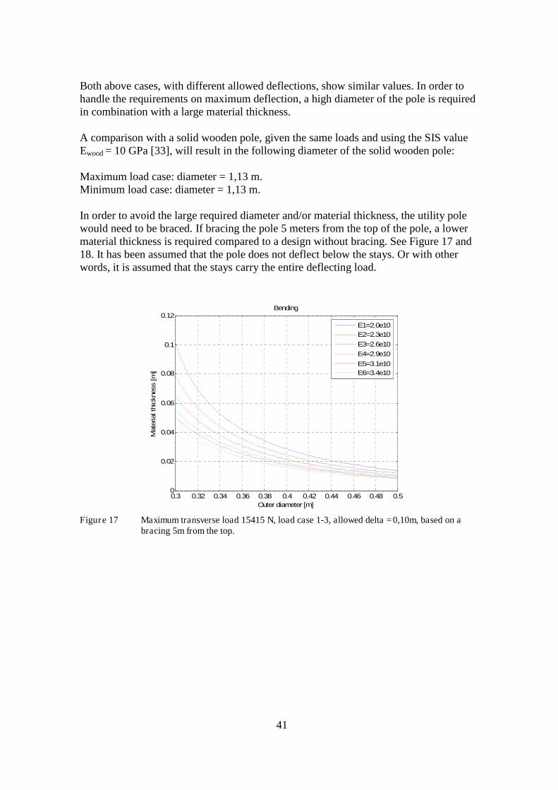
Both above cases, with different allowed deflections, show similar values. In order tohandle the requirements on maximum deflection, a high diameter of the pole is requiredin combination with a large material thickness.
A comparison with a solid wooden pole, given the same loads and using the SIS valueEwood = 10 GPa [33], will result in the following diameter of the solid wooden pole:
Maximum load case: diameter = 1,13 m.Minimum load case: diameter = 1,13 m.
In order to avoid the large required diameter and/or material thickness, the utility polewould need to be braced. If bracing the pole 5 meters from the top of the pole, a lowermaterial thickness is required compared to a design without bracing. See Figure 17 and18. It has been assumed that the pole does not deflect below the stays. Or with otherwords, it is assumed that the stays carry the entire deflecting load.
0.3 0.32 0.34 0.36 0.38 0.4 0.42 0.44 0.46 0.48 0.50
0.02
0.04
0.06
0.08
0.1
0.12
Outer diameter [m]
Mate
rialth
ickness
[m]
Bending
E1=2.0e10
E2=2.3e10
E3=2.6e10
E4=2.9e10
E5=3.1e10
E6=3.4e10
Figure 17 Maximum transverse load 15415 N, load case 1-3, allowed delta =0,10m, based on abracing 5m from the top.
42
0.3 0.32 0.34 0.36 0.38 0.4 0.42 0.44 0.46 0.48 0.50
0.01
0.02
0.03
0.04
0.05
0.06
0.07
0.08
0.09
0.1
Outer diameter [m]
Mate
rialth
ickness
[m]
Bending
E1=2.0e10
E2=2.3e10
E3=2.6e10
E4=2.9e10
E5=3.1e10
E6=3.4e10
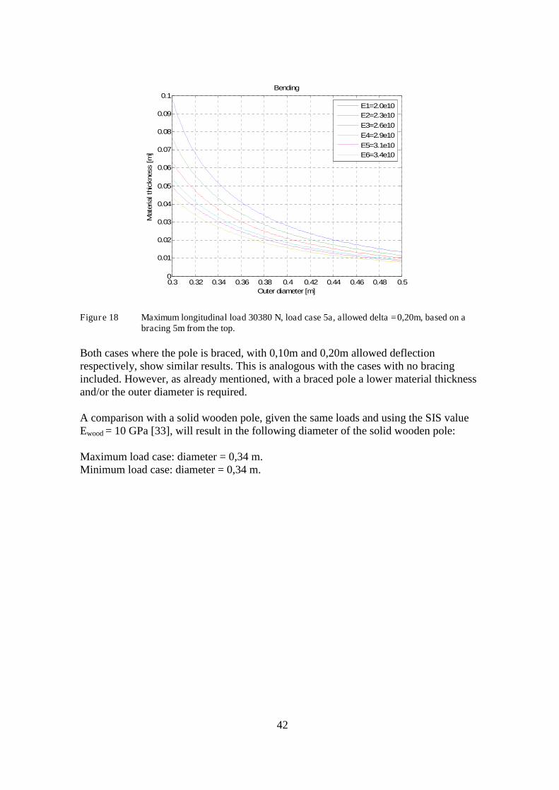
Figure 18 Maximum longitudinal load 30380 N, load case 5a, allowed delta =0,20m, based on abracing 5m from the top.
Both cases where the pole is braced, with 0,10m and 0,20m allowed deflectionrespectively, show similar results. This is analogous with the cases with no bracingincluded. However, as already mentioned, with a braced pole a lower material thicknessand/or the outer diameter is required.
A comparison with a solid wooden pole, given the same loads and using the SIS valueEwood = 10 GPa [33], will result in the following diameter of the solid wooden pole:
Maximum load case: diameter = 0,34 m.Minimum load case: diameter = 0,34 m.

43
7.5 Stress calculations
In this section the compression stress in the 1-direction of the composite pole iscalculated. The calculated value is compared to an experimentally determined maximumvalue of compression strength [1].
A
Plc (9)
where:
lc longitudinal compression strength
P loadA area
Based on the maximum vertical load of 43380 N and a pole with an outer diameter of0,41 m and a material thickness of 0,03 m, the calculations gives a stress value of:
*3,2 clc MPa
Where *c is a glass fiber reinforced polyester (orthophtalic) with a compressive value of
294 MPa [1].
7.6 Conclusions design of utility pole
In the load case of beam bending, i.e. transverse and longitudinal loads, the pole shouldbe braced in order to meet the requirements of maximum deflection, as given by Svenskakräftnät (0,10 m and 0,20 m maximum deflection). It is noteworthy that also a woodenpole needs to be braced in order to fulfill these requirements.
By bracing the pole 5 meters from top, the maximum vertical load will be thedimensioning load case for material thickness and diameter, see Figure 13.
An estimated material thickness, based upon the maximum vertical load graph in Figure13, is approximately 0,03 m, with a pole diameter of 0,41 m. These values are based on aYoung’s modulus of 29 GPa. As seen in the graphs, variations can be made:
A lower Young’s modulus will require a higher material thickness. A smaller pole diameter will require a higher material thickness. A lower material thickness will require a larger pole diameter, or higher Young’s
modulus.
44
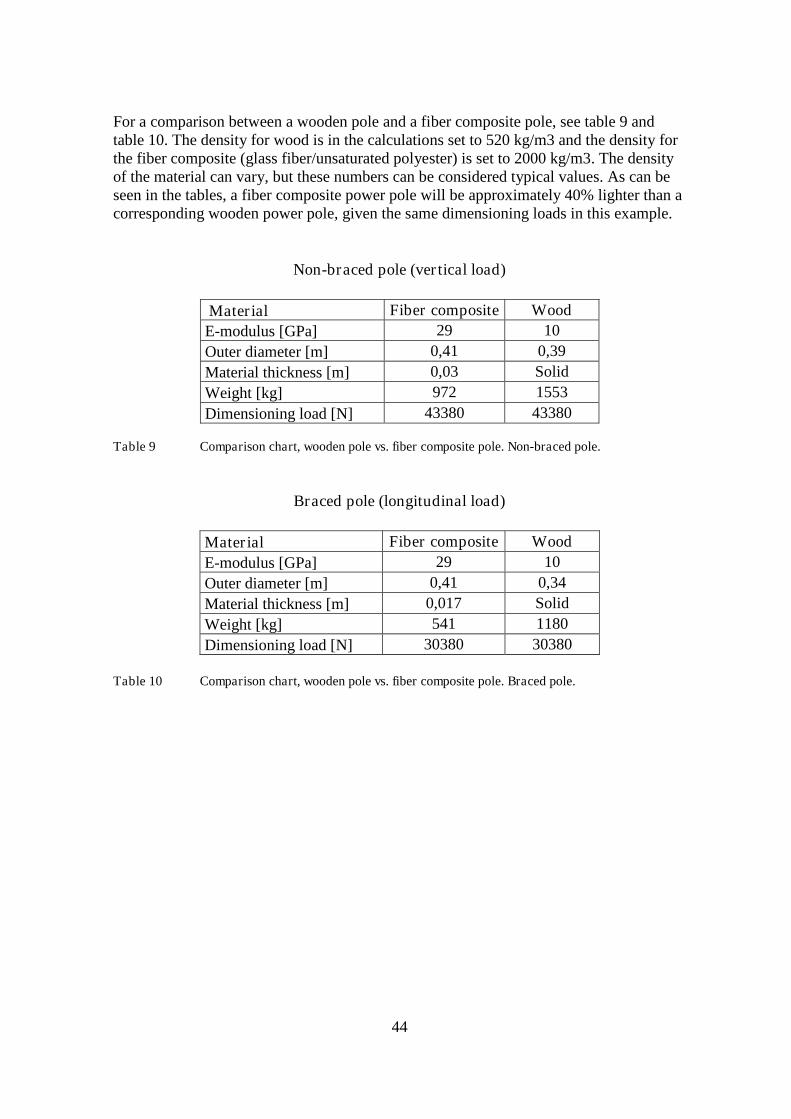
For a comparison between a wooden pole and a fiber composite pole, see table 9 andtable 10. The density for wood is in the calculations set to 520 kg/m3 and the density forthe fiber composite (glass fiber/unsaturated polyester) is set to 2000 kg/m3. The densityof the material can vary, but these numbers can be considered typical values. As can beseen in the tables, a fiber composite power pole will be approximately 40% lighter than acorresponding wooden power pole, given the same dimensioning loads in this example.
Non-braced pole (vertical load)
Material Fiber composite Wood
E-modulus [GPa] 29 10
Outer diameter [m] 0,41 0,39
Material thickness [m] 0,03 Solid
Weight [kg] 972 1553
Dimensioning load [N] 43380 43380
Table 9 Comparison chart, wooden pole vs. fiber composite pole. Non-braced pole.
Braced pole (longitudinal load)
Material Fiber composite Wood
E-modulus [GPa] 29 10
Outer diameter [m] 0,41 0,34
Material thickness [m] 0,017 Solid
Weight [kg] 541 1180
Dimensioning load [N] 30380 30380
Table 10 Comparison chart, wooden pole vs. fiber composite pole. Braced pole.
45
8 Environmental effects
Fiber composite utility poles are generally well suited to withstand many environmentalfactors. The most common environmental factors for a fiber composite utility pole issunlight, with its frequency spectrum including UV-light. Possible biological attacks to autility pole include termite and woodpecker attacks. Other environmental factors areinsects, fungus, corrosive environments and fires.
8.1 UV-light
Ultraviolet light, as part of the sunlight may impact on the fiber composite material. UV-light may cause long-term degradation of the unprotected material and color fading,sometimes referred to as yellowing. Color fading is a problem of aesthetic nature anddoes not significantly influence mechanical properties.
There are several methods to offer UV-protection to the fiber composite, by adding UV-absorbing additives into the matrix resin or by adding a protective outer shell of UV-paint. Some manufacturers combine these methods. See also Section 2.3 Additives.
8.2 Biological factors
The composite material composed of glass fiber and epoxy is not biodegradable. It is notsubject to attacks by fungus or animals/insects, like woodpeckers.
8.3 Corrosion
Fiber composites are not affected by corrosion provided no metal components are used ine.g. attachments or other parts of the construction. This can be seen as a major advantagecompared with pole construction made of steel.
8.4 Fires
Although the polymer matrix of the fiber composite is flammable by terms of being anorganic material, utility poles of fiber composites perform quite well in terms of fireresistance.
The fiber composite utility pole manufacturer Pultrusion has done tests in order to provethe inherent flame resistance. The work was done together with University of Delawareand Reichhold, a company manufacturing unsaturated polyester resins. The tests showedthe fiber composite poles being superior to both treated and untreated timber poles [15].
46
The flame resistance of composite utility poles in field was proven in 2003 during thefire storms in San Diego, California. A Powertrusion utility pole which was mounted fortesting survived the fire, which consumed 3000 utility poles and 1440 km of power lines[15].
8.5 Length of life
The current manufacturers of fiber composite utility pole claim life lengths of about 40-80 years for utility poles based on fiber composites. Poles designed with an outer,protective paint layer might need to get a re-application of fresh paint after 25-30 years.
Due to the fact that fiber composite poles are relatively new, the life length has not beenable to be verified.
9 Recycling
As of today, there are currently no industries or companies in Sweden performingrecycling fiber composites. Due to new requirements for recycling in the future,combined with the increased use of fiber composites, it may however be likely that therewill pop-up companies in the recycling business for fiber composites.
In this chapter, technologies for recycling of fiber-reinforced thermoset polymers arereviewed. For this type of a material, two main types of techniques are available;mechanical recycling and thermal recycling [20,21,22,23].
9.1 Problems in recycling
Polymer based fiber composites are a mixture of materials with quite different propertieswhich does not make the recycling easier: Polymer, reinforcement in the form ofchopped or continuous fibers, and sometimes fillers or additives.
The recycling of fiber-reinforced composites based on thermoplastics should in theory beless difficult than the recycling of material based on thermosets due to the fact thatthermoplastics can be remelted and subsequently used again. A process including re-melting is however not possible for matrix material out of thermosets due to the physicalstructure of the material. During the curing of resin, the polymer molecules arecrosslinked by covalent bonds and form an almost infinite molecule. Due to thecrosslinking, thermosets cannot be remelted or remoulded.
Some thermosetting polymers, including Polyurethane, can however be convertedrelatively easily back to their original monomer. This might be an advantage of usingpolyurethane as matrix in utility poles made of fiber composites.
47
9.2 Mechanical recycling
This technique is based on reducing the size of the fiber components. In the process, thereductions in size starts by crush milling or slow speed cutting the material. Removal ofpossible other inserts, such as metal, is facilitated by this first coarse reduction.
The second step typically include ground or hammer milling the material. The final sizemay vary and can typically be from 10mm down to 50μm.
All of the constituents of the original composite are reduced in size and the resultingmaterial is a mixture of fractions with different size and content. Typically, coarserfractions have slightly higher fiber content whereas the finer fractions have a highercontent of polymer. The latter fractions may be present in form of a powder.
Applications
The finer fractions, i.e. the powder, can be suitable as fillers. For example, powders canbe used as substitute for calcium carbonate filler in new SMC (Sheet MouldingCompounds) techniques.Among different studies that have been made, rest products have also been tested for useas reinforcement in asphalt.
9.3 Thermal processing
Three methods have been found to be developed or tested; Combustion with energyrecovery, Pyrolysis, and Fluidised bed processing.
9.3.1 Combustion with energy recovery
Thermosetting polymers, like other organic material, can be used as an energy source byburning it. Most resins have a calorific value of about 30.000 kJ/kg. This value is true forthe fraction of polymer in the fiber composite. As glass fibers do not burn, one has tolook at the weight fraction of polymer in the fiber composite to estimate the energycontent of e.g. 1 kg composite material.
The non-combustible parts of the fiber composite can be used as cement fillers, althoughgiven some restrictions, for example regarding Boron content in glass fibers.
9.3.2 Pyrolysis
Pyrolysis is the chemical decomposition of organic materials by heating in the absence ofoxygen. Pyrolysis degrades the polymer components of the fiber composite whereby oiland gas products are formed. There will be left overs in the form of fibers and char.
48
9.3.3 Fluidised bed processing
The fluidised bed processing technique enables the re-use of glass fibers in a fibercomposite, as the fibers are recovered with this technique. The University of Nottingham,U.K., has performed a lot of research on the method during the past decade.
The fluidised bed is made up of a bed of silica sand, which is fluidised with a stream ofhot air of a temperature of typically 450-550 ºC. The velocity of the air through the sandbed is typically 0,4-1,0 m/s.
The fiber composite to be recycled is put onto the fluidised bed where the polymer partof the composite will start to vaporize, which releases the fibers, and fillers if anypresent, into the hot gas stream. The fibers are separated in the cyclone for recoverywhereas the gas stream continues to the afterburner chamber, where the polymer parts areoxidized. This stage may also provide energy to be recovered from the combustionproducts as the polymer oxidizes.
A glass fiber reinforced polyester composite can be processed at 450 ºC whereascomposites containing epoxy resin require up to 550 ºC in order to get a quickvaporization.
The recycled fibers show reasonably good mechanical properties. The stiffness of thefibers remains compared to fresh, non-recycled fibers. The tensile strength however isreduced by approximately 50% with a processing temperature of 450 ºC. At highertemperatures, the mechanical strengths will however suffer significantly more; aprocessing temperature of 650 ºC reduces the strength of up to 90%.
The fluidised bed process yields quite clean products. The fibers are clean and haveshown very little surface contamination. The mean length is in the region of 6-10 mm.
As a summary, there are as of today no recycling methods established suitable for glassfiber composites, at least not in Sweden. Several methods are however possible forrecycling fiber composites.
If considering fiber composite utility pole compared with traditional wooden poles froma recycling perspective, it should be noted that the composite material does not includetoxic substances, like creosote which the wooden poles are treated with and might pose aheadache from a recycling perspective.
49
10 Conclusions
It has been shown that utility poles made of fiber composites are already in use, mostly inNorth America where also today’s manufacturers are present. Potential futuremanufacturers do also exist in Scandinavia.
Utility poles of fiber composite may very well be a suitable alternative to the woodenpoles of today. When using wood as material, properties are limited to the naturalproperties of wood. A composite material can be tailored in order to achieve the desiredproperties, e.g. strength, environmental resistance and price to mention a few.
Some of the advantages a composite utility pole has to offer compared with a woodenpole are lesser weight and the resistance against environmental attacks, like fire, fungusand woodpeckers, the latter being a problem of today according to Svenska Kraftnät. Acomposite pole may also be manufactured in several smaller sections and assembled onsite, which can facilitate the transportation of poles. E.g. Resin Systems offer thismodular concept.
Regarding an estimated life expectancy, no real data is available since composite utilitypoles are relatively new. But according to manufacturers, a length of life of 40-80 yearscan be expected. Since the material is not subject to any environmental attacks like rustor fungus, no reason is found against this statement.
The preferential choice of fiber is glass fiber, which also is the choice in today’s presentcomposite utility poles. All existent manufacturers use glass fiber, which has goodmechanical properties to a reasonable price. As matrix, several thermoset polymers canbe used. The manufacturers have different chosen solutions for the matrix. In order tomake a choice of matrix, it is recommended that a thorough requirement specification ismade and different choices are being discussed. This would include suitable additives.
Recycling of a composite utility pole is possible, with some limitations. By using afluidised bed process, the fibers can be recycled for usage. All other processes will give amaterial usable only as filler or reinforcement is other materials. It is howevernoteworthy that new processes may be developed in the future, as there is not yet anymajor demand for composite recycling, the volumes still being relatively low.

50
11 Further work
In order to implement a new, or existent solution for a composite utility pole, a detailedrequirement specification should be formulated where Svenska Kraftnät defines whatdesired properties that should be fulfilled by the material and pole.
The choice of material can be influenced by desired properties, such as electricalproperties, long-term loads, e.t.c. Further work could include defining the requirementson these properties and loads.
As there are power utility companies that use composite poles, contacts could be taken inorder to get experience feed-back from the users of today.
51
12 References
[1] B.T. Åström: Manufacturing of Polymer Composites. Chapman & Hall, 2-6
Boundary Row, London SE1 8HN, UK, 1997. – ISBN 0 412 81960 0
[2] Bengt Sundström “Enaxliga Problem Teknisk Balkteori”. Fingraf AB, Södertälje,
1995
[3] http://www.vetrotexasiapacific.com/business_info/rap_gstrand.html#top (2007)
[4] http:// http://www.azom.com/.azom.com/details.asp?ArticleID=984#_E_Glass_Fiber
(2007)
[5] D. Zenkert , M. Battley ”Foundations of Fiber Composites”, (2003)
[6] http://www.exelcomposites.net/portal/technical/raw_materials/resins/ (2007)
[7] http://www.azom.com/Details.asp?ArticleID=986 (2007)
[8] http://www.ocvreinforcements.com/processes/ (2007)
[9] http://www.svk.se (2007)
[10] P.K. Mallick and S. Newman, Composite Materials Technology, Processes and
Properties, Hanser; New York : Oxford Univ. Press, 1990. ISBN – 3 446 15684 4
[11] Lawrens E.Nielsen and Robert F. Landel, Mechanical Properties of Polymers and
Composites, second edition, New York : Dekker, 1994. ISBN – 0 8247 8964 4
[12] S. Halim Hamid, Handbook of polymer Degradation, New York : Dekker, 2000.
ISBN – 0 8247 0324 3
[13] C.S. Smith, Design of Marine Structures in Composite Materials, (1990)
[14] Güneri Akovali, Handbook of Composite Fabrication, Shawbury : Rapra
Technology, 2001. IBSN – 1 85957 – 263 4
[15] www.reichhold.com (2007)
[16] http://skp-cs.com/ (2007)
[17] https://web.grouprsi.com/rsweb/ (2007)
[18] http://www.powertrusion.com/ (2007)
[19] http://www.strongwell.com/selected_markets/power_poles/index.shtml (2007)
52
[20] S.J. Pickering, Recycling technologies for thermoset composite materials-current
status, The University of Nottingham, UK, (2005)
[21] S.J. Pickering, R.M. Kelly, J.R. Kennerley, C.D. Rudd and N.J. Fenwick, A
fluidised- bed process for the recovery of glass fibres from scrap thermoset composites,
University of Nottingham, UK, (2000)
[22] J.R. Kennerley, R.M, Kelly, N.J Fenwick, S.J. Pickering and C.D. Rudd, The
characterisation and reuse of glass fibres recycled from scrap composites by the action
of a fluidised bed process, The University of Nottingham, UK, (1998)
[23] Adrian M. Cunliffe and Paul T. Williams, Characterisation of products from the
recycling of glass fibre reinforced polyester waste by Pyrolysis, The University of Leeds,
UK, 2003
[24] http://www.exel.net/ (2007)
[25] http://www.fiberline.dk(2007)
[26] Matlab & Simulink student version release 14
[ 27] Sundström, B. (Redaktör). Handbok och formelsamling i Hållfasthetslära.
Stockholm : KTH, 1999
[28] Danberg, H. (Redaktör). Komposithandboken, polymerbaserade fiberkompositer,
Stockholm : Sveriges verkstadsindustrier (VI): Industrilitteratur, 2001 (Klippan :
Ljungberg)
[29] Billmeyer, Fred W.Jr. Textbook of Polymer Science. New York: Wiley, 1984.
IBSN – 0 471 03 196 8
[30] http://www.compositesworld.com/articles/jec-composites-2007-product-
showcase.aspx(2007)
[31] http://www.compositesworld.com/articles/evaluating-the-market-for-composite-
poles-cross-arms-and-composite-reinforced-cabling.aspx(2007)
[32] www.reichhold.com/composites/casestudy.cfm?ID=23(2007)
[33] Svensk Standard SS 436 01 04, utgåva 6, Svenska Elektriska kommissionen


![RStandard Pole Design Guide - Composite Utility Poles Poles Pole Design... · RStandard Pole Design Guide ... pole structures the M1L should only be used in poles up to 65 ft. [15.2m]](https://img.pdfslide.net/doc/110x75/5a8140f87f8b9a9d308d1097/rstandard-pole-design-guide-composite-utility-poles-pole-designrstandard-pole.jpg)