Embed Size (px)
Citation preview
PROCESS AUTOMATION
FOR HAZARDOUS, CLASS II APPLICATIONS
Explosion prevention techniques are readily available for use in industrial and agricultural areas. This paper will highlight some of these
techniques and provide some practical application knowledge to consider.
Mike MendicinoProduct Manager
PREVENTING DUST EXPLOSIONS

PREVENTING DUST EXPLOSIONS
2Singapore: +65-6779-9091
[email protected]: +1 330-486-0002
[email protected]: +49 621-776-2222
[email protected]+Fuchs Groupwww.pepperl-fuchs.com
Subject to modifications without notice Copyright Pepperl+Fuchs
Image property of U.S. Chemical Safety & Hazard Investigation Board. Used with permission
Preventing Dust Explosions
Protecting Your Process
On February 7, 2008, an explosion occurred at the Imperial Sugar Company refinery in Portwentworth, Georgia. The explosion and resulting fire left 13 people dead, 42 people injured, and the plant destroyed. Sugar dust is being cited as the cause of the explosion. This is just the latest dust related explosion causing death, personal injury, and property loss. Five years earlier, on January 29, 2003, there was an explosion and fire at a pharmaceutical plant in Kinston, North Carolina. This resulted in six deaths, dozens of injuries, and hundreds of job losses. The facility produced rubber stoppers and other products for medical use. The explosion was fueled by an accumulation of fine plastic powder (dust) on a ceiling suspended over a manufacturing area. That same year, dust would be established as the likely source for explosions at 25 other plants in the United States, including two others in North Carolina and three in Kentucky. The following year, 28 other plants in 19 states would have dust explosions. In all, federal investigators say there have been 281 explosions nationwide over the past 25 years.
Some died horribly in these explosions. Yet every death could have been prevented, according to the Chemical Safety Board’s investigation.
“You can prevent dust explosions for almost nothing,” said Bill Kauffman, a professor at the University of Michigan and a leading expert on dust explosions who took part in the CSB hearing. His prescription is simple: “Remove the Dust.” (Source: “Excerpts from CSB Public Hearing on Hazards of Combustible Dust.” CSB Safety Videos, Vol 1. DVD. 2007.)
Many common items including flour, nondairy creamer, wood, and aluminum are far more lethal than gun powder if they are
reduced to a dust and suspend in the air. “All it takes is a single spark to set them off,” Kauffman said. (Source: “Excerpts from CSB Public Hearing on Hazards of Combustible Dust.” CSB Safety Videos, Vol 1. DVD. 2007.)
Grain silos, coal-unloading facilities, and refineries all have the characteristics of a potentially explosive dust environment. Each of these sites have areas that could be considered hazardous due to the presence of an explosive material in the atmosphere. A small spark from activating a switch or heat produced from a pump can ignite the dust and create an explosion or fire.
CSB investigationCompounding the problem in the safety industry has been a continual lack of interest in dust explosions.
The Chemical Safety Board (CSB) is a federal agency that investigates industrial chemical accidents and hazards. In a report issued in November of 2006 it detailed industry shortcomings. These include lax or nonexistent government regulations and enforcement, haphazard warning systems, and a lack of awareness about the danger posed by dust. (The full report can be viewed at online at http://www.csb.gov/index.cfm?folder=completed_investigation&page=info&INV_ID=53.)
Most people are amazed at the number of everyday materials that can cause an explosion under certain conditions. Examples of well-known materials that have a potential to explode include coal, sugar, corn, steel wool, propane, and methane. Other materials susceptible to explosion that are not well known include aspirin,
artificial sweeteners, cornstarch, pasta, tapioca, egg white dusts,
tea, instant coffee, coffee creamer, cocoa, tobacco, wood and paper dusts, laser toner, paint pigment, aluminum, and most plastics. As a result, hazards exist in many industries. This includes the food processing, pharmaceutical, cosmetics, automotive, aircraft, computer, refining, ethanol, metal, and textile industries.

3Singapore: +65-6779-9091
[email protected]: +1 330-486-0002
[email protected]: +49 621-776-2222
[email protected]+Fuchs Groupwww.pepperl-fuchs.com
Subject to modifications without notice Copyright Pepperl+Fuchs
What is a dust explosion?A dust explosion occurs when a fine dust suspended in air is ignited, causing a very rapid burning. In milliseconds, gaseous products are released with a subsequent pressure rise of explosive force that will damage property and injure people. Dust explosions can be categorized into two phases: primary and secondary.
A primary explosion takes place in a confined atmosphere (such as a silo or part of the manufacturing plant) with the resulting shock wave damaging and often rupturing the plant. This allows the products of the explosion (burning dust and gases) to be expelled into the surrounding area. This disturbs any settled dust and initiates a larger secondary explosion. The secondary explosion can cause severe damage to surrounding plant buildings. Most large-scale dust explosions result from chain reactions of this type.
What conditions are necessary for a dust explosion?1. The dust must be combustible.
2. The dust must be fine. The finer the dust the more explosive it is likely to be.
3. The dust cloud must be of explosive concentration, i.e. between the lower and upper explosive limits for that particular dust.
4. There must be sufficient oxygen in the atmosphere to support and sustain combustion.
5. There must be a source of ignition.
Typical dust parameters
Cloud ignition energy 5 mJ and higherMinimum explosive concentration 0.02 oz/ft3 and higherMaximum pressure developed 30-150 psiRate of pressure rise less than 15,000 psi/secIgnition temperature-cloud 200°C and higherIgnition temperature-layer 150°C and higher
Table 1. Typical dust parameters
Values reported by the United States Bureau of Mines
(Source: Ernest C. Magison, Electrical Instruments in Hazardous Locations, 3rd ed. (Pittsburgh: Instrument Society of America, ca.
1978), 317, Table 11-1.)
Whether one is considering metallic, carbonaceous, plastic, chemical, or agricultural dusts, the values in table 1 are typical.
The table points out the most significant difference between Class I gas or vapor hazards and Class II dust hazards. Though other characteristics are similar, the ignition energy of the most easily ignited industrial dust is 20 times greater than the typical Class I Group D material. Only a few dusts, such as zirconium and thorium hydride, ignite at energies below 10 mJ. Under certain conditions, these dusts will spontaneously ignite at room temperature.
R. K. Eckhoff published a book entitled, Towards Absolute Minimum Ignition Energies For Dust Clouds. In the book, Eckhoff includes a study discussing how little is known about the minimum ignition energy of dust clouds compared to the that of gases and vapors. In the study he also compares his data to the data of the U. S. Bureau of Mines. Unlike Eckhoff, the Bureau of Mines tested dusts at higher voltages through larger resistances. This study is of interest because it helps explain the dust ignition phenomena.
PREVENTING DUST EXPLOSIONS
4Singapore: +65-6779-9091
[email protected]: +1 330-486-0002
[email protected]: +49 621-776-2222
[email protected]+Fuchs Groupwww.pepperl-fuchs.com
Subject to modifications without notice Copyright Pepperl+Fuchs
Eckhoff’s evidence supports his hypothesis that very short capacitor discharge times, about 1 µs, cause pressure waves around the arc which may force dust particles away from the arc. Slower discharges, on the order of a few tenths to several milliseconds, correlate with a reduced stored ignition energy and do not disrupt the dust cloud.
Eckhoff also measured spark-ignition energies lower than those reported by the Bureau of Mines. He used a capacitive discharge circuit in which an auxiliary capacitor provided a short trigger pulse to break down an air gap, which then discharged the capacitor storing the “ignition energy.”
InertingOne common method to reduce the hazard of dust explosions is to prevent the combustible material from reaching an explosive concentration by purging or ventilating the area. This prevents the accumulation of a combustible atmosphere. Other ways to minimize the risk of explosion is to reduce the oxygen content or add moisture or a dry inert material. In coal mines it is common practice to coat the galleries and shafts with rock dust to reduce the likelihood of coal dust explosions. The inert material adds thermal capacity without increasing the energy released by combustion. Adding the inert material also increases the amount of energy required to ignite the combustible elements of the atmosphere - much like holding a lit match to a wet log.
Carbon dioxide is usually the diluent for oxygen content. It is a more effective diluent than nitrogen. At high temperatures water vapor is as effective as carbon dioxide. Many metal dusts react with water, and moisture may increase explosion severity. Because of this, argon and helium are preferred diluents for metal dusts. These are used extensively in the metals industry.
Electrical devices for dusty locationsThere are two objectives in Class II locations: (1) Keep the dust away from ignition sources; (2) Prevent ignition of dust that accumulates on the device.
There are five commonly used methods to accomplish this.
1. Dust-ignition-proof enclosures (Division 1)2. Dust-tight enclosures (Division 2).3. Purging Pressurization (Division 1 and 2)4. Sealing (Division 2)5. Intrinsic Safety (Division 1)
Dust–ignition-proof, and Dust-tight enclosures are described in the 2011 NEC (National Electric Code).
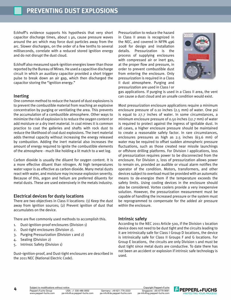
Pressurization to reduce the hazard in Class II areas is recognized in the NEC, and covered in NFPA 496 2008 for design and installation details. Pressurization is the process of supplying enclosures with compressed air or inert gas, at the proper flow and pressure, in order to prevent combustible dust from entering the enclosure. Only pressurization is required in a Class II dust atmosphere. Purging and pressurization are used in Class I or gas applications. If purging is used in a Class II area, the vent can cause a dust cloud and an unsafe condition would exist.
Most pressurization enclosure applications require a minimum enclosure pressure of 0.10 inches (2.5 mm) of water. One psi is equal to 27.7 inches of water. In some circumstances, a minimum enclosure pressure of 0.50 inches (12.7 mm) of water is required to protect against the ingress of ignitable dust. In all cases, a higher enclosure pressure should be maintained to create a reasonable safety factor. In rare circumstances, enclosures pressures as high as 2.5 inches (63.6 mm) of water may be required to offset sudden atmospheric pressure fluctuations, such as those created near missile launchings or offshore drilling platforms. For Division I applications, loss of pressurization requires power to be disconnected from the enclosure. For Division 2, loss of pressurization allows power to remain on, provided an audible or visual alarm notifies the operator of the condition. Motors, transformers, and other devices subject to overload must be provided with an automatic means to de-energize them if the temperature exceeds the safety limits. Using cooling devices in the enclosure should also be considered. Vortex coolers provide a very inexpensive solution. However, the pressurization measurement must be capable of handling the increased pressure or the system must be reprogrammed to compensate for the added air pressure within the enclosure.
Intrinsic safetyAccording to the NEC 2011 Article 500, if the Division 1 location device does not need to be dust tight and the circuits leading to it are intrinsically safe for Class I Group D locations, the device is intrinsically safe for Class II Groups F and G locations. For Group E locations, the circuits are only Division 1 and must be dust tight since metal dusts are conductive. To date there has not been an accident or explosion if intrinsic safe technology is used.

5Singapore: +65-6779-9091
[email protected]: +1 330-486-0002
[email protected]: +49 621-776-2222
[email protected]+Fuchs Groupwww.pepperl-fuchs.com
Subject to modifications without notice Copyright Pepperl+Fuchs
What is intrinsic safety?Intrinsic safety is a type of protection in which a portion of the electrical system contains equipment (apparatus, circuits, and wiring) that is not capable of causing ignition in the surrounding atmosphere under normal or abnormal conditions. This is accomplished by using isolated barriers which have specifically designed matching RLC (resistance, inductance, and capacitance) circuits with redundant zener diodes, transformers, resistors, and fuses to limit over voltage or dead shorting due to accidental damage. The wiring length, or distance, adds to the resistance and capacitance and needs to be considered when calculating the RLC of the system. Keeping intrinsically safe wires separate from the standard wiring by a set distance (usually 2 inches) in a cable tray prevents accidents. No special armor sheathing, as in explosion proof wiring, is required. Intrinsic safety protects the whole system within the hazardous area. A practical benefit of intrinsic safety technology is that a technician can work on live circuits without injury to himself/herself or the process and without shutting down the process. Equipment in this category must not be capable of causing ignition in normal operation, with a single fault, or with any two independent faults. A safety factor of 1.5 must be applied to relevant ignition data for the normal operation or single fault conditions, and a 1.0 for two fault condition.
Rupture disks and monitorsVarious explosion protection methods are permitted. Often combinations of protection measures present the best engineering and financial solution. A commonly used protection method is a combination of explosion relief venting (rupture disks, explosion doors or panels) and explosion suppression. Rupture discs are thin metal or foil diaphragms placed in the pipe or vessel. The discs are designed to burst, or “rupture,” when pressure inside the system reaches a certain point. The diaphragm is sometimes scored so the disc will rupture at a lower pressure. Many of the rupture disk and explosion door manufacturers monitor these passive devices electronically though intrinsic safety barriers and in purged cabinets. When
the mechanical disc or door ruptures, the switch is opened and a logic circuit instantaneously activates. With this additional solution applied, the process is made much safer.
Conclusion–How to prevent and control the hazard:1. Maintain effective housekeeping. If dust is not there, it
cannot ignite as a layer or be dispersed as a cloud.
2. Maintain handling equipment to keep dust inside. Clean up any dust that escapes. Even small accumulations of dust (as small as 1/32 of an inch) can create a dust explosion hazard if spread over a sufficient surface area.
3. Conduct workforce training and education courses regarding the recognition and control of combustible dust hazards.
4. Design machinery and plant to minimize damage if an explosion occurs. Use flame arresters to prevent flames from spreading and vents to relieve pressure and reduce structural damage.
5. Use intrinsically safe wiring practices.
6. House electrical equipment in purged or pressurized cabinets.
7. Detect the early pressure rise when an explosion occurs in a closed system and suppress it with an inerting material.
8. Material Safety Data Sheets (MSDS) rarely address how explosive a material may be. They merely state that the material may explode. Moreover, not all MSDS can be relied on to address the possibility of explosion. This can lead to the material being mishandled if the user(s) assume that the material cannot explode. Frequently, product manufacturers are not sufficiently aware of their material’s volatility. As a result, the material may not be tested for explosiveness because it is not thought of as explosive. Sometimes a product may not be explosive in the form in which it is supplied, but can become explosive once it is processed. This can happen in grinding and pulverizing operations or through abrading.
9. Knowing a material’s minimum ignition energy and minimum ignition temperature (MIE and MIT) is fundamental for arriving at HAZOP. A material with a high ignition energy or temperature is more difficult to ignite than a material with low values, except in the presence of open flames or welding operations. The MIT for dispersed dust is used to ensure that surface temperatures cannot cause the dust to ignite. The MIT value of the dust cloud and powder layer are relevant parameters for selecting suitable electrical equipment used in dusty environments.
PREVENTING DUST EXPLOSIONS
6Singapore: +65-6779-9091
[email protected]: +1 330-486-0002
[email protected]: +49 621-776-2222
[email protected]+Fuchs Groupwww.pepperl-fuchs.com
Subject to modifications without notice Copyright Pepperl+Fuchs
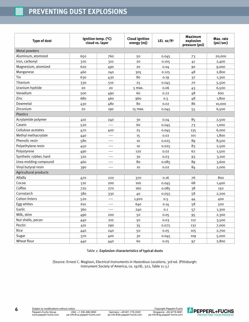
Type of dust Ignition temp. (°C) cloud vs. layer
Cloud ignition energy (mJ) LEL oz/ft3
Maximum explosion
pressure (psi)
Max. rate (psi/sec)
Metal powders
Aluminum, atomized 650 760 50 0.045 73 20,000
Iron, carbonyl 320 310 20 0.105 41 2,400
Magnesium, atomized 620 490 20 0.04 90 9,000
Manganese 460 240 305 0.125 48 2,800
Tin 630 430 80 0.19 37 1,300
Titanium 330 510 25 0.045 70 5,500
Uranium hydride 20 20 5 max. 0.06 43 6,500
Vanadium 500 490 60 0.22 48 600
Zinc 680 460 960 0.5 48 1,800
Dowmetal 430 480 80 0.02 86 10,000
Zirconium 20 190 15 max. 0.045 55 6,500
Plastics
Acrylamide polymer 410 240 30 0.04 85 2,500
Casein 520 ---- 60 0.045 73 1,000
Cellulose acetates 470 400 25 0.045 135 6,000
Methyl methacrylate 440 ---- 15 0.02 101 1,800
Phenolic resin 580 ---- 10 0.025 89 8,500
Polyethylene resin 450 ---- 10 0.025 83 2,500
Polystyrene 490 ---- 120 0.02 62 1,500
Synthetic rubber, hard 320 ---- 30 0.03 93 3,100
Urea molding compound 460 ---- 80 0.085 89 3,600
Vinyl butyral resin 390 ---- 10 0.02 84 2,000
Agricultural products
Alfalfa 470 220 370 0.16 76 800
Cocoa 510 200 100 0.045 68 1,400
Coffee 720 270 160 0.085 38 150
Cornstarch 380 330 40 0.055 58 2,200
Cotton linters 520 ---- 1,920 0.5 44 400
Egg whites 610 ---- 640 0.14 58 500
Garlic 360 ---- 240 0.1 57 1,300
Milk, skim 490 200 50 0.05 95 2,300
Nut shells, pecan 440 210 50 0.03 112 3,500
Pectin 410 290 35 0.075 132 7,000
Rice 440 240 50 0.05 105 2,700
Sugar 370 400 30 0.045 109 5,000
Wheat flour 440 440 60 0.05 97 2,800
Table 2. Explosion characteristics of typical dusts
(Source: Ernest C. Magison, Electrical Instruments in Hazardous Locations, 3rd ed. (Pittsburgh: Instrument Society of America, ca. 1978), 322, Table 11-3.)

7Singapore: +65-6779-9091
[email protected]: +1 330-486-0002
[email protected]: +49 621-776-2222
[email protected]+Fuchs Groupwww.pepperl-fuchs.com
Subject to modifications without notice Copyright Pepperl+Fuchs
Notes

5 1
8
4
2
6
7
3
Subject to modifications • © 2012 PEPPERL+FUCHS, INC. • Printed in USA • TDOCT-1503BUSA
www.pepperl-fuchs.us
PROCESS AUTOMATION – PROTECTINg yOUR PROCESS
Worldwide/german Headquarters Pepperl+Fuchs GmbH Mannheim · GermanyTel. +49 621 776 2222E-Mail: [email protected]
1
Asia Pacific HeadquartersPepperl+Fuchs PTE Ltd. SingaporeCompany Registration No. 199003130ETel. +65 6779 9091E-Mail: [email protected]
2
Central/Western Europe & Africa HeadquartersPepperl+Fuchs N.V. Schoten/Antwerp · BelgiumTel. +32 3 6442500E-Mail: [email protected]
3
Middle East HeadquartersPepperl+Fuchs M.E (FZE) Dubai · UAETel. +971 4 883 8378E-Mail: [email protected]
4
North/Central America Headquarters Pepperl+Fuchs Inc. Twinsburg · Ohio · USATel. +1 330 486 0002E-Mail: [email protected]
5
Northern Europe HeadquartersPepperl+Fuchs GB Ldt. Oldham · EnglandTel. +44 161 6336431E-Mail: [email protected]
6
Southern/Eastern Europe HeadquartersPepperl+Fuchs Elcon srl Sulbiate · ItalyTel. +39 039 62921E-Mail: [email protected]
7
Southern America HeadquartersPepperl+Fuchs Ltda. São Bernado do Campo · SP · BrazilTel. +55 11 4341 8448E-Mail: [email protected]
8
For over a half century, Pepperl+Fuchs has provided new concepts for the world of process automation. Our company sets standards in quality and innovative technology. We develop, produce and distribute electronic interface modules, Human-Machine Interfaces and hazardous location protection equipment on a global scale, meeting the most demanding needs of industry. Resulting from our world-wide presence and our high flexibility in production and customer service, we are able to offer complete individual solutions – wherever and whenever you need us. We are the recognized experts in our technologies – Pepperl+Fuchs has earned a strong reputation by supplying the world’s largest process industry companies with the broadest line of proven components for a diverse range of applications.