Embed Size (px)
Citation preview
Proceedings World Geothermal Congress 2015
Melbourne, Australia, 19-25 April 2015
1
Prevention of Casing Failures in Ultra-Deep Geothermal Wells (Germany)
David Lentsch, Klaus Dorsch, Natascha Sonnleitner, Achim Schubert
Erdwerk GmbH, Bonner Platz 1, D-80803 Munich, Germany
Keywords: ultra-deep geothermal wells, overpressured zones, tectonic stresses, casing failures, casing collapse, Germany, Molasse
Basin, casing design, cementing techniques, advanced drilling technologies
ABSTRACT
About 40 deep geothermal wells have been drilled successfully in the last 10 years in the Molasse Basin of southern Germany. To
date, this is the deepest low-mid enthalpy hydrothermal exploration in a sedimentary basin worldwide. Some of the wells are 6000
m (20,000 ft) deep. In the coming years, even deeper and more challenging wells are planned. Most of the wells are highly
productive, and the exploration and development efforts to date have been successful. However, drilling and well completion in this
geological setting close to the Alps with high tectonic stresses and overpressured zones is challenging. Moreover, high temperature
fluids that are produced with high flow rates through the casing string induce additional stresses. Consequently, one of the major
problems in the past was casing failures. Therefore, a study was performed to identify the mechanisms and reasons for casing
failures. A catalogue of these measures was then developed that serves as a guideline in the planning and construction phase of a
drilling project. These measures primarily involve adaptions of former guidelines used in the design of casings, the utilization of
advanced drilling and completion technologies, and guidelines for the selection, placement, and quality control of cement. This
paper provides a summary of the findings in our study and describes the measures that are necessary to avoid casing failures in deep
geothermal wells in the Molasse Basin in southern Germany or in comparable deep sedimentary basins.
1. INTRODUCTION
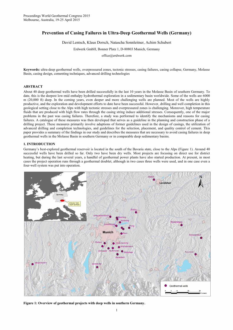
Germany’s best-explored geothermal reservoir is located in the south of the Bavaria state, close to the Alps (Figure 1). Around 40
successful wells have been drilled so far. Only two have been dry wells. Most projects are focusing on direct use for district
heating, but during the last several years, a handful of geothermal power plants have also started production. At present, in most
cases the project operation runs through a geothermal doublet, although in two cases three wells were used, and in one case even a
four-well system was put into operation.
Figure 1: Overview of geothermal projects with deep wells in southern Germany.
Lentsch et al.
2
The low-mid enthalpy reservoir is located in a typical sedimentary peripheral foreland basin of late Eocene to Miocene age with a
highly permeable carbonate reservoir of Upper Jurassic age (the so called Malm aquifer) at the base of this asymmetric basin.
Towards the south, the depth of the reservoir increases up to 5000 m and along with this the temperature of the thermal water
increases with maximum values 150-160°C. The thickness of the Malm carbonates is around 500-600 m. Within this limestone, the
porosity is strongly controlled by the facies of the rocks. Reef limestone (mass facies) is favorable in terms of hydraulic
conductivity. Bedded or layered marly limestone, on the other hand, shows low hydraulic conductivity. Other considerations also
play a role in optimizing the development of the reservoir, such as diagenetic processes (dolomitization, karstification), existing
fault systems, and the orientation of faults. The initial use of this reservoir started decades ago when the thermal water of
unsuccessful oil wells was used for spas.
Since the beginning of this millennium, there has been exploration for geothermal energy, which started in the northern and central
part of the Molasse Basin with drilling depths of a maximal 3000 m. In more recent years, the exploration has moved southwards,
and along with this, the drilling depths of the deviated wells exceeded 6000 m. Generally, state-of-the-art technologies from the oil
and gas industries were used to drill these wells. However, there are several distinctive attributes that are different. The most
essential are: Firstly, high flow rates and production directly through the casing string. The estimated flow rates in most cases were
> 100 l/s, especially in the power projects. This requires large diameter boreholes to reduce friction pressure losses and a corrosion
resistive design to ensure long-lasting well integrities. Secondly, the reservoir section is not cemented and requires completion that
enables high flow from the reservoir into the wellbore as well as borehole stability. Finally, massive lost circulation in the reservoir
section requires special consideration in drilling and in casing design. The wells drilled in the southern and deeper part of the basin
make additional demands on the drilling technology due to the length of the wells, high tectonic stresses, and overpressured zones.
The wells in the south also produce water with higher temperatures above 150°C. Especially during the start of the production the
increasing production temperatures lead to high loads on the casing strings.
This paper describes the problems and failures in these wells that have been identified in the past, the lessons learned, and
recommended adaptions in the design for future wells.
2. PROBLEM OVERVIEW
This section outlines geological hazards and production challenges of geothermal wells drilled in the southern part of the Molasse
Basin.
2.1 Geological Hazards
Apart from several geological challenges for drilling and well construction like unconsolidated sediments, swelling clays, highly
permeable layers with the risk of fluid losses or differential sticking, oil or gas bearing formations, abrasive sandstones, etc., the
major challenge for drilling and for the casing integrity of deep wells close to the Alps are caused by zones under high tectonic
stress or high overpressure.
2.1.1 Overpressured Zones
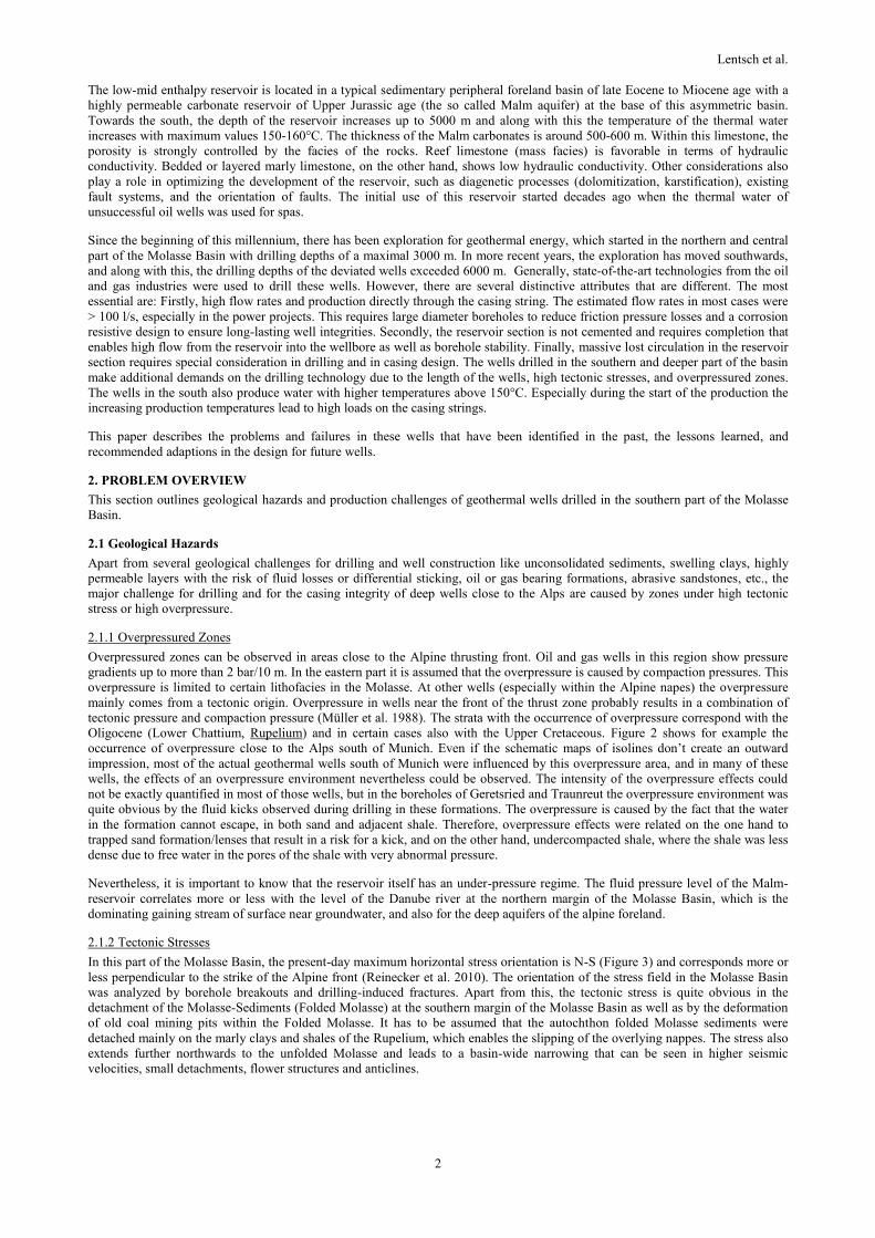
Overpressured zones can be observed in areas close to the Alpine thrusting front. Oil and gas wells in this region show pressure
gradients up to more than 2 bar/10 m. In the eastern part it is assumed that the overpressure is caused by compaction pressures. This
overpressure is limited to certain lithofacies in the Molasse. At other wells (especially within the Alpine napes) the overpressure
mainly comes from a tectonic origin. Overpressure in wells near the front of the thrust zone probably results in a combination of
tectonic pressure and compaction pressure (Müller et al. 1988). The strata with the occurrence of overpressure correspond with the
Oligocene (Lower Chattium, Rupelium) and in certain cases also with the Upper Cretaceous. Figure 2 shows for example the
occurrence of overpressure close to the Alps south of Munich. Even if the schematic maps of isolines don’t create an outward
impression, most of the actual geothermal wells south of Munich were influenced by this overpressure area, and in many of these
wells, the effects of an overpressure environment nevertheless could be observed. The intensity of the overpressure effects could
not be exactly quantified in most of those wells, but in the boreholes of Geretsried and Traunreut the overpressure environment was
quite obvious by the fluid kicks observed during drilling in these formations. The overpressure is caused by the fact that the water
in the formation cannot escape, in both sand and adjacent shale. Therefore, overpressure effects were related on the one hand to
trapped sand formation/lenses that result in a risk for a kick, and on the other hand, undercompacted shale, where the shale was less
dense due to free water in the pores of the shale with very abnormal pressure.
Nevertheless, it is important to know that the reservoir itself has an under-pressure regime. The fluid pressure level of the Malm-
reservoir correlates more or less with the level of the Danube river at the northern margin of the Molasse Basin, which is the
dominating gaining stream of surface near groundwater, and also for the deep aquifers of the alpine foreland.
2.1.2 Tectonic Stresses
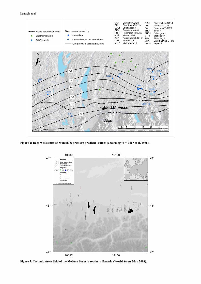
In this part of the Molasse Basin, the present-day maximum horizontal stress orientation is N-S (Figure 3) and corresponds more or
less perpendicular to the strike of the Alpine front (Reinecker et al. 2010). The orientation of the stress field in the Molasse Basin
was analyzed by borehole breakouts and drilling-induced fractures. Apart from this, the tectonic stress is quite obvious in the
detachment of the Molasse-Sediments (Folded Molasse) at the southern margin of the Molasse Basin as well as by the deformation
of old coal mining pits within the Folded Molasse. It has to be assumed that the autochthon folded Molasse sediments were
detached mainly on the marly clays and shales of the Rupelium, which enables the slipping of the overlying nappes. The stress also
extends further northwards to the unfolded Molasse and leads to a basin-wide narrowing that can be seen in higher seismic
velocities, small detachments, flower structures and anticlines.
Lentsch et al.
3
Figure 2: Deep wells south of Munich & pressure-gradient isolines (according to Müller et al. 1988).
Figure 3: Tectonic stress field of the Molasse Basin in southern Bavaria (World Stress Map 2008).

Lentsch et al.
4
2.2 PRODUCTION CHALLENGES FOR CASING DESIGN
2.2.1 Flow Rates and Friction Pressure Losses
The Malm aquifer is under-pressured. Therefore, ESP pumps are used to lift the fluid to the surface during production. The overall
efficiency of a project is highly dependent on the power consumption of that pump. The pressure head at a certain flow rate
depends on the inflow performance of the well, the static fluid level height, and the friction pressure losses in the production casing.
The latter is mostly determined by the diameter of casing strings and the length of the well. Therefore, for deep wells with high
productivity, large diameters are necessary. As a rule of thumb, wells which are longer than 4000 m and which should produce
above 90 l/s are usually completed with a 7” perforated liner in the reservoir section, sometimes even with an open hole completion
in the reservoir. Wells below that production rate and length are usually completed with a 5” perforated liner in the reservoir
section. Due to geological and technical reasons, the deeper wells in the south of the basin require the drilling of five sections. To
end up with a 7” liner requires a surface casing of 20” in diameter and casings with special drift and clearance in between that limits
clearance and wall thickness.
2.2.2 Artificial Lift Installations
The ESP pumps used for production need to have large diameters to achieve the required flow rates whilst having a long service
life. Therefore, the upper part of the well requires a diameter large enough to run in the ESP-Installation.
2.2.3 Production Temperatures
The average geothermal gradient in the Molasse Basin is approximately 30°C/km. Nevertheless in regional scale positive and
negative thermal anomalies appear. The wells drilled to depths of 5000 meters produce water with temperatures of around 150-
160°C. Additionally, the wells have to be designed for potential used as both producer and injector. Therefore, the wells also have
to be designed to resist the load of cold-water injection.
2.2.4 Chemistry of Production Fluids
The thermal water of the Malm aquifer can be characterized as meteoric waters with difference in high influence of saline
formation water. Nevertheless, it is generally characterized by comparatively low mineralization (TDS mainly around or less than
1g/l). The H2S content is correlated with the gas loading of the water and increases towards the central basin. It is considered that
the H2S content in the central basin is on the one hand related to thermochemical sulfate reduction in the southern part with high
reservoir depths and temperatures and on the other hand to bacterial sulfate reduction with a more shallow depth of the reservoir
further north (Mayrhofer et al. 2014). Therefore, the occurrence of H2S in the gas phase has to be considered during casing design.
3. CRITICAL STANDARD LOAD CASES
In a deep geothermal well drilled in the Molasse Basin the following standard load cases determine casing design:
3.1. Surface Casing
The surface casing design (if used as production casing) is highly determined by the production load case. To be more specific, the
temperature rise during production will induce high compressional loads to the casing and casing couplings. Also, corrosion from
shallow formation groundwater has to be considered.
3.2. Drilling Tieback
If the surface casing is used as a production casing a drilling tieback is required to ensure sufficient annular velocity for the drilling
mud and surface casing protection during drilling. The design of the drilling tieback is highly determined by the production load
case (the drilling tieback may be remain installed during the production tests). Again, high compressional loads will be induced due
to the increase of temperature during production.
3.3 First Intermediate Liner
The design of the next string, which is typically a liner, is determined by three load cases. Firstly, the production load case, which
induces high compressional loads due the increasing temperature, is considered again. Secondly, consideration of the (very
realistic) case of a partly evacuated casing due to fluid losses in the reservoir section, which will lead to high collapse loads.
Thirdly, the load case of gas kick from the overpressured zones of deeper sections that lead to high burst loads.
3.4 Second Intermediate Liner
The design of the second intermediate liner is determined by production load cases where the fluid level drop within the wellbore is
the highest due to the additional drawdown of the airlift (during testing) or ESP (during production). This is because in this section
overpressured zones and formations under high tectonic stresses are to be expected which means that high outer pressure superpose
with low inner pressure. Therefore, high collapse loads will be the result.
3.5 Third Intermediate Liner
The design of the third intermediate liner is usually determined by the load case of injecting cold water for stimulation or
reinjection purposes. The decrease in temperature will induce high tensile stresses to the casing and couplings.
3.6 Production Liner
The production liner is generally a pre-perforated liner that prevents brittle borehole breakouts that block the well from flowing. It
is only designed for the load during installation.

Lentsch et al.
5
4. IDENTIFIED CASING FAILURE MECHANISMS IN FORMER WELLS
Three main problems, which caused casing collapse events alone or in combination with each other, have been identified:
1. Annular pressure build-up (APB)
2. Overpressured zones
3. Tectonic stresses
Four casing collapses are discussed in this section. Three failures can be directly assigned to APB. The fourth collapse was caused
by an overpressured zone and/or tectonic stress.
4.1 Collapse Due to Annular Pressure Build-Up (APB)
Mostly, the casing and liner strings of geothermal wells in the Molasse Basin are cemented over their full length. However there are
some scenarios that encounter fluids behind the casing:
1) During cement thickening time, fluid separates due to gravity settling effects in the cement/water mixture and gathers on
top of the cement column.
2) Poor displacement of the drilling fluid. For example, mud is left behind the casing walls that cannot be mobilized in the
course of the cementation.
During production such pockets of water-based fluids will expand when temperatures rise in the well and the annulus. However, if
the fluid cannot expand, the pressure will rise and may exceed collapse strength of the inner string before the outer string bursts.
Potential problem locations are in the liner-surface casing overlap, between the surface pipe and conductor, between tiebacks and
surface pipe, or in sections where the collapse rating of the casing is below the pore pressure (in the case of permeable formations)
or the frac-gradient (in the case of impermeable formations).
4.1.1 Examples of Casing Collapse due to Annular Pressure Build-Up
Collapse 1: The first casing collapse occurred during a first production test with a production rate of 30-50 l/s in a depth of 2300 m
MD. The casing collapse is located at a casing-liner overlap with a packer above the Liner Hanger. Therefore the cause was
attributed to thermal fluid expansion in the annular space between the casing and liner.
Collapse 2: During production start of the well, a casing collapse was detected at about 15 m depth. The failure analysis showed
that the cement column between 18.5/8” and 13.3/8” and the casing was below surface and the pressure release valve of the annulus
was closed. In this way the pressure was able to build up in the annular space during production and caused the collapse of the
13.3/8” casing.
Collapse 3: The third collapse occurred after a production test in the 9.5/8” casing at a depth of 2500 m. The cause is likely due to
APB because the collapse rating of that casing was below the pore pressure of the formation and the cement bond log indicated
poor cementation. However, also buckling could have been the reason in this case.
4.1.2 Theoretical Discussion and Modeling of Annular Pressure Build-Up
Annular pressure build-up is a well-known problem in the geothermal and oil & gas industry. A number of authors (Oudeman and
Kerem 2004, Klementich and Jellison 1986, Adams 1991, MacEachran and Adams 1991, Halal and Mitchell 1993) have proposed
theoretical models to calculate APB.
Oudeman and Kerem (2004) concisely describe how APB can be modeled in HP/HT wells. The following expression can be used
to determine the change in pressure in the annulus (adapted from Oudeman and Kerem, 2004):
1 1
o
t
ann leak
t ann ann
V Vp dT
V V
(1)
Where: κ ............ isothermal compressibility of the annular liquid
γ ............ isobaric thermal expansion coefficient of the annular fluid
Vann ........ annular volume
∆Vleak ..... amount of fluid leaking off the annulus while heating up
∆Vann ..... change in annular volume due to thermal expansion or “ballooning” (compression due to APB) of the
surrounding casing/cement sheet
The expression has three summands which add up to the resulting annular pressure build up: Firstly, the pressure build-up due to
the increase of temperature from t0 to t when the fluid cannot expand in volume. Secondly, the pressure change due to the volume
changes of the enclosing casings (volume change due to pressure build-up and thermal expansion). Thirdly, the pressure change due
to fluid leak-off or influx from the formation.
Lentsch et al.
6
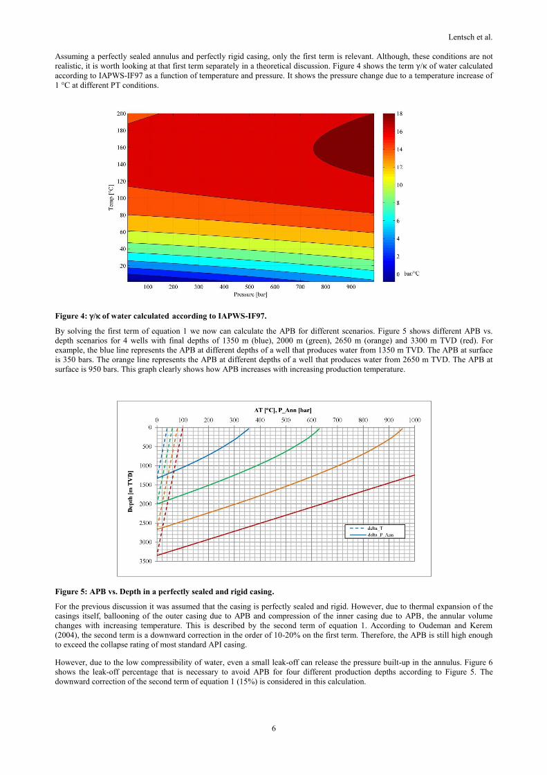
Assuming a perfectly sealed annulus and perfectly rigid casing, only the first term is relevant. Although, these conditions are not
realistic, it is worth looking at that first term separately in a theoretical discussion. Figure 4 shows the term γ/κ of water calculated
according to IAPWS-IF97 as a function of temperature and pressure. It shows the pressure change due to a temperature increase of
1 °C at different PT conditions.
Figure 4: γ/κ of water calculated according to IAPWS-IF97.
By solving the first term of equation 1 we now can calculate the APB for different scenarios. Figure 5 shows different APB vs.
depth scenarios for 4 wells with final depths of 1350 m (blue), 2000 m (green), 2650 m (orange) and 3300 m TVD (red). For
example, the blue line represents the APB at different depths of a well that produces water from 1350 m TVD. The APB at surface
is 350 bars. The orange line represents the APB at different depths of a well that produces water from 2650 m TVD. The APB at
surface is 950 bars. This graph clearly shows how APB increases with increasing production temperature.
Figure 5: APB vs. Depth in a perfectly sealed and rigid casing.
For the previous discussion it was assumed that the casing is perfectly sealed and rigid. However, due to thermal expansion of the
casings itself, ballooning of the outer casing due to APB and compression of the inner casing due to APB, the annular volume
changes with increasing temperature. This is described by the second term of equation 1. According to Oudeman and Kerem
(2004), the second term is a downward correction in the order of 10-20% on the first term. Therefore, the APB is still high enough
to exceed the collapse rating of most standard API casing.
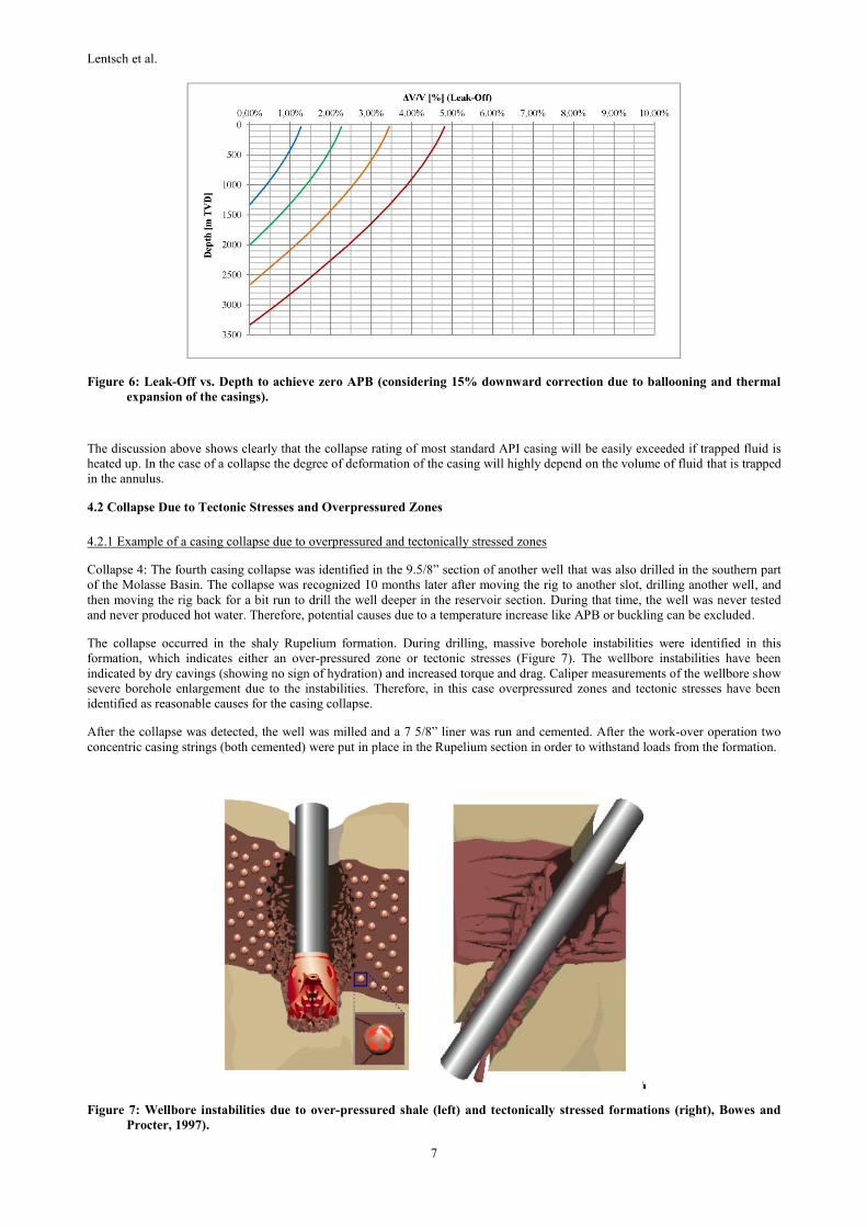
However, due to the low compressibility of water, even a small leak-off can release the pressure built-up in the annulus. Figure 6
shows the leak-off percentage that is necessary to avoid APB for four different production depths according to Figure 5. The
downward correction of the second term of equation 1 (15%) is considered in this calculation.
Lentsch et al.
7
Figure 6: Leak-Off vs. Depth to achieve zero APB (considering 15% downward correction due to ballooning and thermal
expansion of the casings).
The discussion above shows clearly that the collapse rating of most standard API casing will be easily exceeded if trapped fluid is
heated up. In the case of a collapse the degree of deformation of the casing will highly depend on the volume of fluid that is trapped
in the annulus.
4.2 Collapse Due to Tectonic Stresses and Overpressured Zones
4.2.1 Example of a casing collapse due to overpressured and tectonically stressed zones
Collapse 4: The fourth casing collapse was identified in the 9.5/8” section of another well that was also drilled in the southern part
of the Molasse Basin. The collapse was recognized 10 months later after moving the rig to another slot, drilling another well, and
then moving the rig back for a bit run to drill the well deeper in the reservoir section. During that time, the well was never tested
and never produced hot water. Therefore, potential causes due to a temperature increase like APB or buckling can be excluded.
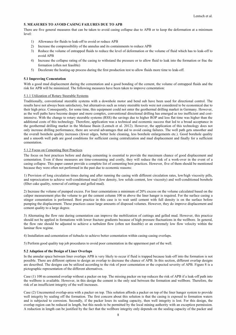
The collapse occurred in the shaly Rupelium formation. During drilling, massive borehole instabilities were identified in this
formation, which indicates either an over-pressured zone or tectonic stresses (Figure 7). The wellbore instabilities have been
indicated by dry cavings (showing no sign of hydration) and increased torque and drag. Caliper measurements of the wellbore show
severe borehole enlargement due to the instabilities. Therefore, in this case overpressured zones and tectonic stresses have been
identified as reasonable causes for the casing collapse.
After the collapse was detected, the well was milled and a 7 5/8” liner was run and cemented. After the work-over operation two
concentric casing strings (both cemented) were put in place in the Rupelium section in order to withstand loads from the formation.
Figure 7: Wellbore instabilities due to over-pressured shale (left) and tectonically stressed formations (right), Bowes and
Procter, 1997).
Lentsch et al.
8
5. MEASURES TO AVOID CASING FAILURES DUE TO APB
There are five general measures that can be taken to avoid casing collapse due to APB or to keep the deformation at a minimum
level:
1) Allowance for fluids to leak-off to avoid or reduce APB
2) Increase the compressibility of the annulus and its containments to reduce APB
3) Reduce the volume of entrapped fluids to reduce the level of deformation or the volume of fluid which has to leak-off to
avoid APB
4) Increase the collapse rating of the casing to withstand the pressure or to allow fluid to leak into the formation or frac the
formation (often not feasible)
5) Decelerate the heating-up process during the first production test to allow fluids more time to leak-off.
5.1 Improving Cementation
With a good mud displacement during the cementation and a good bonding of the cement, the volume of entrapped fluids and the
risk for APB will be minimized. The following measures have been taken to improve cementation:
5.1.1 Utilization of Rotary Steerable Systems
Traditionally, conventional steerable systems with a downhole motor and bend sub have been used for directional control. The
results have not always been satisfactory, but alternatives such as rotary steerable tools were not considered to be economical due to
their high price. Consequently, for some time, this equipment could not enter the geothermal drilling market in Germany. However,
as the well paths have become deeper and more complex, conventional directional drilling has emerged as too inefficient and cost-
intensive. With the change to rotary steerable systems (RSS) the savings due to higher ROP and less flat time was higher than the
additional costs of this technology. Therefore, application was a technical and economic success that led to a broad acceptance in
the geothermal drilling market in the Molasse Basin (Lentsch et al. 2012). However, the application of this technology does not
only increase drilling performance, there are several advantages that aid to avoid casing failures. The well path gets smoother and
the overall borehole quality increases (fewer edges, better hole cleaning, less borehole enlargements etc.). Good borehole quality
and a smooth well path are good conditions for sufficient casing centralization and mud displacement and finally for a sufficient
cementation.
5.1.2 Focus on Cementing Best Practices
The focus on best practices before and during cementing is essential to provide the maximum chance of good displacement and
cementation. Even if these measures are time-consuming and costly, they will reduce the risk of a work-over in the event of a
casing collapse. This paper cannot provide a complete list of cementing best practices. However, five of them should be mentioned
because they were often not performed in the past due to economic reasons:
1) Provision of long circulation times during and after running the casing with different circulation rates, low/high viscosity pills,
and reprocication to achieve well-conditioned mud (low density, low solids content, low viscosity) and well-conditioned borehole
(filter cake quality, removal of cuttings and gelled mud).
2) Increase the volume of pumped excess. For liner cementations a minimum of 20% excess on the volume calculated based on the
caliper measurement plus the volume to get the cement column 100 m above the liner hanger is required. For the surface casing a
stinger cementation is performed. Best practice in this case is to wait until cement with full density is on the surface before
pumping the displacement. These practices cause large amounts of disposed volumes. However, they do improve displacement and
cement quality to a large degree.
3) Alternating the flow rate during cementation can improve the mobilization of cuttings and gelled mud. However, this practice
should not be applied in formations with lower fracture gradients because of high pressure fluctuations in the wellbore. In general,
the flow rate should be adjusted to achieve a turbulent flow (often not feasible) or an extremely low flow velocity within the
laminar flow regime.
4) Installation and cementation of tiebacks to achieve better cementation within casing-casing overlaps.
5) Perform good quality top job procedures to avoid poor cementation in the uppermost part of the well.
5.2 Adaption of the Design of Liner Overlaps
In the annular space between liner overlaps APB is very likely to occur if fluid is trapped because leak-off into the formation is not
possible. There are different options to design an overlap to decrease the chance of APB. In this section, different overlap designs
are described. The designs can be utilized according to the risk of poor cementation or the expected severity of APB. Figure 8 is a
pictographic representation of the different alternatives.
Case (1) 100 m cemented overlap without a packer on top. The missing packer on top reduces the risk of APB if a leak-off path into
the wellbore is available. However, in this design the cement is the only seal between the formation and wellbore. Therefore, the
risk of an insufficient integrity of the well increases.
Case (2) Uncemented overlap-area with a packer on top. This solution affords a packer on top of the liner hanger system to provide
well integrity by sealing off the formation. The first concern about this solution is that the casing is exposed to formation waters
and is subjected to corrosion. Secondly, if the packer loses its sealing capacity, then well integrity is lost. For this design, the
overlap region can be reduced in length, but this needs to be permitted by the local mining authority with an exception permission.
A reduction in length can be justified by the fact that the wellbore integrity only depends on the sealing capacity of the packer and

Lentsch et al.
9
the length of overlap has no influence on it. Due to the fact that the area is uncemented, travel joints need to be placed in this region
to compensate for temperature expansion and to prevent buckling of the casing string. However, with every travel joint added to the
design there are additional weak points in terms of well integrity.
Case (3) Perforate the outer casing wall. This design allows overpressure to be bled off to the formation. Therefore, the outer casing
must be perforated in the section of the overlap, where fluid behind the casing is expected. However, there are some concerns about
this method since the casing is exposed to formation fluids that trigger corrosion. The liner section needs to be completed with a
packer on top to ensure well integrity. The design loses its capabilities if the liner cannot be run to the predefined setting depth.
Case (4) Burst disks below the liner hanger. Burst disks are installed, which act as a predetermined breaking point. Once a
sufficiently high pressure builds up behind the casing wall, the burst disks are activated and cause communication between the
annulus and the well. Burst disks are designed in a way that they break before the casing is damaged. The placement of burst disks
is the crucial element; if they are placed in a well-cemented region they lose their function. The advantage is that this system works
even if the liner cannot be run to the predefined depth.
Case (5) A compressible spacer of fluid designed to compensate for fluid expansion can be placed in the overlap between the casing
and liner. The challenge is to place the spacer right below the liner hanger packer installation. There are uncertainties concerning
the open hole volume, the volume pumped into the borehole, and effects causing the cement to channel upwards. Apart from the
placement problem, with the application of this method the character of the cement in providing stability to the casing is lost.
Another concern is the stability of the compressible spacer in terms of its physical properties.
Case (6) Crushable foam wrap. Crushable foam wraps are meant to be wrapped around the casing to provide volume that is not
cemented behind the casing wall. This volume is able to compensate for fluid expansion once it occurs. This is of a very fragile
design, so running to depth in a well with high inclination without any damage could be a challenge.
Figure 8: Pictographic representation of different overlap design alternatives.
5.3 Production Starting Procedures
When starting the production of the well, flow rates should be kept low or pumping should be stopped several times before full
production temperature is reached. Slowly heating the casing will provide more time for entrapped water in the casing annuli to
leak-off through any flow paths towards the formation.
5.4 Consideration of Pore and Fracture Pressures in the Selection of Casing Collapse Rating
To avoid APB in the annular between casing and formation the casing collapse resistance should exceed the pore pressure or even
the fracture pressure of the formation. This will provide fluid leak-off into the formation prior to a casing collapse. However,
especially for large diameter casings at larger depths, this is often not feasible or practical.
6. MEASURES TO AVOID CASING FAILURES DUE TO TECTONIC STRESSES AND OVERPRESSURED ZONES
Conservative risk analysis regarding tectonically stressed or overpressured zones should be carried out prior to the well design.
During casing design, conservative assumptions regarding pressure gradients should be made. For tectonically stressed formations a
pressure gradient of 2 - 2.2 bar/10 m should be assumed. For pore pressure gradients the values according to Müller et al. (1988) or
offset wells should be used.
7. ADDITIONAL MEASURES TO REDUCE THE RISK OF CASING FAILURES FOR ALL LOAD CASES
7.1 Focus on Casing Protection During Drilling Operations
Deviated wells with build-up sections and high-angle tangents lead to high side forces between the drill string and the casing during
drilling and tripping operations. Non-rotating protectors have been used successfully to prevent casing wear, which would
immediately reduce casing strength. Besides the effect of less wear, they also reduce torque and drag while drilling. Protector
placement has to be planned carefully to minimize tripping time due to the rearrangement of protectors and to cover the most
critical zones during all operations.
Lentsch et al.
10
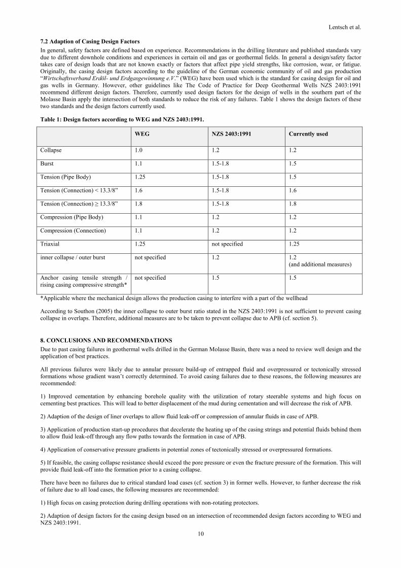
7.2 Adaption of Casing Design Factors
In general, safety factors are defined based on experience. Recommendations in the drilling literature and published standards vary
due to different downhole conditions and experiences in certain oil and gas or geothermal fields. In general a design/safety factor
takes care of design loads that are not known exactly or factors that affect pipe yield strengths, like corrosion, wear, or fatigue.
Originally, the casing design factors according to the guideline of the German economic community of oil and gas production
“Wirtschaftsverband Erdöl- und Erdgasgewinnung e.V.” (WEG) have been used which is the standard for casing design for oil and
gas wells in Germany. However, other guidelines like The Code of Practice for Deep Geothermal Wells NZS 2403:1991
recommend different design factors. Therefore, currently used design factors for the design of wells in the southern part of the
Molasse Basin apply the intersection of both standards to reduce the risk of any failures. Table 1 shows the design factors of these
two standards and the design factors currently used.
Table 1: Design factors according to WEG and NZS 2403:1991.
WEG NZS 2403:1991 Currently used
Collapse 1.0 1.2 1.2
Burst 1.1 1.5-1.8 1.5
Tension (Pipe Body) 1.25 1.5-1.8 1.5
Tension (Connection) < 13.3/8” 1.6 1.5-1.8 1.6
Tension (Connection) ≥ 13.3/8” 1.8 1.5-1.8 1.8
Compression (Pipe Body) 1.1 1.2 1.2
Compression (Connection) 1.1 1.2 1.2
Triaxial 1.25 not specified 1.25
inner collapse / outer burst not specified 1.2 1.2
(and additional measures)
Anchor casing tensile strength /
rising casing compressive strength*
not specified 1.5 1.5
*Applicable where the mechanical design allows the production casing to interfere with a part of the wellhead
According to Southon (2005) the inner collapse to outer burst ratio stated in the NZS 2403:1991 is not sufficient to prevent casing
collapse in overlaps. Therefore, additional measures are to be taken to prevent collapse due to APB (cf. section 5).
8. CONCLUSIONS AND RECOMMENDATIONS
Due to past casing failures in geothermal wells drilled in the German Molasse Basin, there was a need to review well design and the
application of best practices.
All previous failures were likely due to annular pressure build-up of entrapped fluid and overpressured or tectonically stressed
formations whose gradient wasn’t correctly determined. To avoid casing failures due to these reasons, the following measures are
recommended:
1) Improved cementation by enhancing borehole quality with the utilization of rotary steerable systems and high focus on
cementing best practices. This will lead to better displacement of the mud during cementation and will decrease the risk of APB.
2) Adaption of the design of liner overlaps to allow fluid leak-off or compression of annular fluids in case of APB.
3) Application of production start-up procedures that decelerate the heating up of the casing strings and potential fluids behind them
to allow fluid leak-off through any flow paths towards the formation in case of APB.
4) Application of conservative pressure gradients in potential zones of tectonically stressed or overpressured formations.
5) If feasible, the casing collapse resistance should exceed the pore pressure or even the fracture pressure of the formation. This will
provide fluid leak-off into the formation prior to a casing collapse.
There have been no failures due to critical standard load cases (cf. section 3) in former wells. However, to further decrease the risk
of failure due to all load cases, the following measures are recommended:
1) High focus on casing protection during drilling operations with non-rotating protectors.
2) Adaption of design factors for the casing design based on an intersection of recommended design factors according to WEG and
NZS 2403:1991.
Lentsch et al.
11
REFERENCES
Adams, A.J.: How to design for annulus fluid heat-up, SPE 22871, presented at the SPE Annulal Technical Conference and
Exhibition, Dallas TX (October 6-9, 1991)
Bowes, C., Procter, R.: Drillers Stuck Pipe Handbook, Guidelines & Drillers Handbook Credits (1997)
Halal, A.S. and Mitchell, R.F.: Casing design for trapped annulus pressure buildup, SPE/IADC 25694, presented at the SPE/IADC
Drilling Conference, Amsterdam (February 23-25, 1993)
Heidbach, O., Tingay, M., Barth, A., Reinecker, J., Kurfeß, D., and Müller, B.: The World Stress Map database release 2008
doi:10.1594/GFZ.WSM.Rel2008
Klementich, E. and Jellison, M.J.: A Service Life Model for Casing Strings, SPE Drilling Engineering, (April 1986) 141-152
Lentsch, D., Savvatis, A., Schubert, A., and Schoebel, W.: Overcoming Drilling Challenges With Rotary Steerable Technology in
Deep Geothermal Wells in the Molasse Basin of Southern Germany, GRC Transactions, Vol. 36 (2012), 165-169
Lubinski A.L., Althouse W. S., and Logan, J.L. Helical Buckling of tubing Sealed in Packers, JPT, (June 1962), 655-670
MacEachran, A. and Adams A.J.: Impact on Casing Design of Thermal Expansion of Fluids in Confined Annuli, SPE/IADC 21911,
presented at the SPE/IADC Drilling Conference Amsterdam (February 2-4, 1991)
Mayrhofer, C., Niessner, R., and Baumann, T.: Hydrochemistry and hydrogen sulfide generating processes in the Malm aquifer,
Bavarian Molasse Basin, Germany, Hydrogeology Journal, Vol. 22 (2014), 151-162
Müller, M., Nieberding F., and Wanninger, A.: Tectonic style and pressure distribution at the northern margin of the Alps between
Lake Constance and the River Inn, Geologische Rundschau, Vol. 77/3 (1988), 787-769.
NZS 2403:1991, New Zealand Standard, Code of practice for Deep Geothermal Wells, Standards Association of New Zealand
Oudeman P. and Kerem M..: Transient Behavior of Annular Pressure Build-up in HP/HT Wells, SPE 88735, presented at the 11th
Abu Dhabi International Petroleum Exhibition and Conference (October 10-13, 2004)
Reinecker, J., Tingay, M., Müller, B., and Heidbach, O.: Present-day stress orientation in the Molasse Basin, Tectonophysics, Vol.
482 (2010), 129-138
Southon, J. N. A.: Geothermal Well Design, Construction and Failures, Proceedings World Geothermal Congress 2005, Auckland,
New Zealand (2005)
The International Association for the Properties of Water and Steam: Revised Release on the IAPWS Industrial Formulation 1997
for the Thermodynamic Properties of Water and Steam, Lucerne, Switzerland (August 2007)