Embed Size (px)
Citation preview
Catalog No. L51524e
PIPELINE RISER SYSTEM DESIGN AND APPLICATION GUIDE
PR-178-622
Prepared for the Onshore/Offshore Supervisory Committee
Pipeline Research Committee
of Pipeline Research Council International, Inc.
Prepared by the following Research Agencies:
Brown and Root U.S.A., Inc.
Publication Date: February 1987
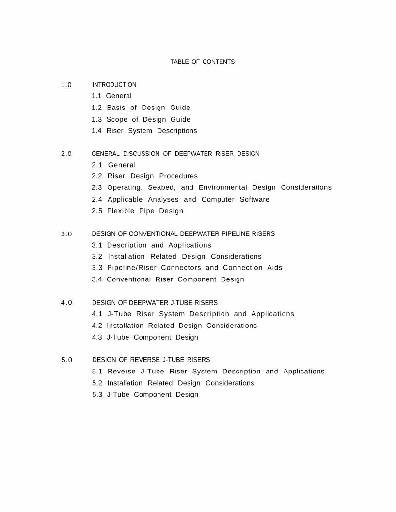
TABLE OF CONTENTS
1.0 INTRODUCTION
1.1 General
1.2 Basis of Design Guide
1.3 Scope of Design Guide
1.4 Riser System Descriptions
2.0 GENERAL DISCUSSION OF DEEPWATER RISER DESIGN
2.1 General
2.2 Riser Design Procedures
2.3 Operating, Seabed, and Environmental Design Considerations
2.4 Applicable Analyses and Computer Software
2.5 Flexible Pipe Design
3.0 DESIGN OF CONVENTIONAL DEEPWATER PIPELINE RISERS
3.1 Description and Applications
3.2 Installation Related Design Considerations
3.3 Pipeline/Riser Connectors and Connection Aids
3.4 Conventional Riser Component Design
4.0 DESIGN OF DEEPWATER J-TUBE RISERS
4.1 J-Tube Riser System Description and Applications
4.2 Installation Related Design Considerations
4.3 J-Tube Component Design
5.0 DESIGN OF REVERSE J-TUBE RISERS
5.1 Reverse J-Tube Riser System Description and Applications
5.2 Installation Related Design Considerations
5.3 J-Tube Component Design
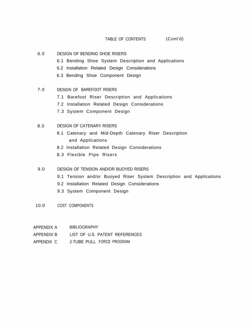
TABLE OF CONTENTS (Cont'd)
6.0 DESIGN OF BENDING SHOE RISERS
6.1 Bending Shoe System Description and Applications
6.2 Installation Related Design Considerations
6.3 Bending Shoe Component Design
7.0 DESIGN OF BAREFOOT RISERS
7.1 Barefoot Riser Description and Applications
7.2 Installation Related Design Considerations
7.3 System Component Design
8.0 DESIGN OF CATENARY RISERS
8.1 Catenary and Mid-Depth Catenary Riser Description
and Applications
8.2 Installation Related Design Considerations
8.3 Flexible Pipe Risers
9.0 DESIGN OF TENSION AND/OR BUOYED RISERS
9.1 Tension and/or Buoyed Riser System Description and Applications
9.2 Installation Related Design Considerations
9.3 System Component Design
10.0 COST COMPONENTS
APPENDIX A BIBLIOGRAPHY
APPENDIX B LIST OF U.S. PATENT REFERENCES
APPENDIX C J-TUBE PULL FORCE PROGRAM
SECTION 1.0 INTRODUCTION
1.1 General
1.2 Basis of Design Guide
1.3 Scope of Design Guide
1.4 Riser System Descriptions
1.4.1 Conventional Riser
1.4.2 J-Tube Riser
1.4.3 Reverse J-Tube
1.4.4 Bending Shoe
1.4.5 Barefoot Riser
1.4.6 Free Spanning Risers
Section 1.0 - List of Figures
FigureNo. T i t l e
1-1
1-2
Platform Types
Current Riser Systems (Steel Pipe)
2.0 GENERAL DISCUSSION OF DEEPWATER RISER DESIGN
2.1 General
2.1.1 Deepwater Risers - Fixed and Compliant Platforms
2.1.2 Deepwater Risers - Moored Platforms
2.2 Riser Design Procedures
2.2.1 Phase I - Preliminary Engineering
2.2.2 Phase II - Detai led Engineering
2.2.3 Phase III - Material Procurement
2.2.4 Phase IV - Construction
2.3 Operating, Seabed, and Environmental Design Considerations
2.3.1 Seabed Soils
2.3.2 Operating Conditions
2.3.3 Wave and Current Loadings
2.3.4 Platform Motions
2.3.5 Platform Settlement
2.4 Applicable Analyses and Computer Software
2.4.1 Operational Stress Analysis
2.4.2 Instal lat ion Stress Analysis
2.4.3 Analysis of Tensioned and Buoyed Risers
2.5 Flexible Pipe Design
2.5.1 Flexible Pipe Manufacturers
2.5.2 Flexible Pipe Construction
2.5.3 End Fittings
2.5.4 Flexible Pipe Properties
Section 2.0 - List of Figures
FigureNo. T i t l e
2-1 Sequence o f E v e n t s f o r D e e p w a t e r R i s e r D e s i g n a n d
Construction
2-2 Preliminary Engineering for Deepwater Riser Design
2-3 Phase II - Detailed Engineering for Deepwater Riser Design
2-4 Phase III - Mater ia l Procurement Sequence of Events for
Deepwater Risers
2-5 Phase IV - Construction Sequence of Events for Deepwater
Risers
2-6 Pipeline Expansion Equations
2-7 Conventional Riser Computer Model
2-8 Basic Pipe Stress Equations
SECTION 3.0 DESIGN OF CONVENTIONAL DEEPWATER PIPELINE RISERS
3.1 Descript ion and Applicat ions
3.1.1 Riser System Components
3.1.2 Deep Water Applications/Limitations
3.2 Instal lat ion Related Design Considerations
3.2.1 Instal lat ion Scenarios
3.2.2 Riser Ins ta l la t ion
3.2.3 Pipeline/Riser Connections (w/Diver Intervention)
3.2.4 Pipeline/Riser Connections (Diverless)
3.2.5 Pipeline End Target Area
3.2.6 Riser Location
3.3 Pipeline/Riser Connectors and Connection Aids
3.3.1 Mechanical Connectors
3.3.2 Connector Aids
3.4 Conventional Riser Component Design
3.4.1 Flexibi l i ty at Lower Riser Section
3.4.2 Flexibi l i ty of Vert ical Riser/Deck Piping
3.4.3 Riser Supports
3.4.4 Corrosion Protection Measures
3.4.5 Repairability/Mid-Riser Connectors
Section 3.0 - List of Figures
FigureNo. T i t l e
3-1 Typical Platform Riser Instal lat ion
3-2 Typical Platform Riser Instal lat ion with Offset
3-3 Riser Guide Rail System
3-4 Spring Loaded Diverless Clamp
3-5 Slotted Keyhole Typer Riser Support (Diverless)
3-6 Conven t i ona l R i se r I ns ta l l a t i on Us ing S lo t t ed Keyho le
Riser Supports (Fab r i ca ted & Up r i gh ted w i t h F loa t i ng
Equipment)
3-7 Conven t i ona l R i se r I ns ta l l a t i on Us ing S lo t t ed Keyho le
Riser Supports (Fabricated on Tower)
3-8 Diver Assisted Spool Piece Installation
3-9 Pipe Lifting Procedures
3-10 Underwater Habitat (UWH) and Submersible Pipe Alignment
Rig (SPAR)
3-11 Diverless Spool Piece Installation Procedure
3-12 Sled- to-Receiver Pul l - in Ins ta l la t ion
3-13 One Atmosphere Pull -In Procedure
3-14 Pipeline End Positioning in Deepwater
3-15 Steel and Flexible Pipe Expansion Loops
3-16 Upper Riser Supports
3-17 Intermediate Riser Clamps
SECTION 4.0 DESIGN OF DEEPWATER J-TUBE RISERS
4.1 J-Tube Riser System Description and Applications
4.1.1 System Components
4.1.2 Applicat ions/Limitat ions
4.2 Installation Related Design Considerations
4.2.1 Startup and Termination of Pipelay
4.2.2 Pull-in Procedures
4.2.3 Pipeline Approach
4.2.4 Deck Space Requirements for Pull Equipment
4.3 J-Tube Component Design
4.3.1 J-Tube Conduit
4.3.2 J-Tube Exit and Pipe Span
4.3.3 Riser Pipe String
4.3.4 Pipel ine
4.3.5 Platform Appurtenances
4.3.6 Corrosion Protection Measures
4.3.7 Flexible Pipe J-Tube Risers
FigureNo.
4-1
4-2
4-3
4-4
4-5
4-6
4-7
4-8
4-9
4-10
4-11
Section 4.0 - List of Figures
T i t l e
J-Tube Riser Instal lat ion
J-Tube Pull Force vs. Back Tension for Example Cases
J-Tube Pull Force vs. J-Tube Radius for Example Cases
J-Tube Pull Force vs. Clearance Ratio for Example Cases
J-Tube Minimum Radius vs. Riser Pipe Wall Thickness
(24" O.D. Riser Pipe in 2,500 ft. Water Depth)
Typica l J -Tube Insta l la t ion Procedure ( In termi t tent Pu l l
Off Conventional Vessel)
Second End J-Tube Pull-In Procedure
Typical J-Tube Installation Procedure (Continuous Pull)
Typical J-Tube Pull Winch Arrangement on Platform Deck
J-Tube Conduit Configuration Showing Stepped Down Conduit
Size and Mid-Length Connections for Mult i-Piece Jacket
Installation (Shell Cognac 12-Inch Line)
Releasable J-Tube Mouth
SECTION 5.0 DESIGN OF REVERSE J-TUBE RISERS
5.1 Reverse J-tube Riser System Description and Applications
5.1.1 System Components
5.1.2 Applicat ions/Limitat ions
5.2 Installation Related Design Considerations
5.2.1 Pipe Transfer Equipment
5.2.2 Deck Space Requirements for Equipment
5.2.3 Production Rates
5.2.4 Anodes on Pipe Pulled Through Riser
5.2.5 Pipeline Approach
5.3 J-tube Component Design
5.3.1 J-tube Conduit
5.3.2 J-tube Exit and Reverse Bend
5.3.3 Riser Pipe String
5.3.4 Corrosion Protection Measures
FigureNo.
5-1
5-2
5-3
5-4
Section 5.0 - List of Figures
T i t l e
Reverse J-Tube Installation
Reverse J-Tube Pull Equipment
Reverse J-Tube Pull Platform Configuration
Riser Pipe Elevator Slip
SECTION 6.0 DESIGN OF BENDING SHOE RISERS
6.1 Bending Shoe System Description and Applications
6.1.1 System Components
6.1.2 Applicat ions/Limitat ions
6.2 Installation Related Design Considerations
6.2.1 Startup and Termination of Pipelay
6.2.2 Pipeline Approach
6.2.3 Pipeline Line-up/Uprighting
6.3 Bending Shoe Component Design
6.3.1 Bending Shoe
6.3.2 Riser Pipe String
6.3.3 Pipel ine
6.3.4 Riser Supports
6.3.5 Platform Appurtenances
FigureNo.
6-1
6-2
6-3
6-4
Section 6.0 - List of Figures
T i t l e
Bending Shoe Riser Installation
Pipel ine Posit ioning for Bending Shoe Instal lat ion During
Pipeline Abandonment
Bending Shoe Arrangement for Example 24-Inch Uprighting
Riser Upr ight ing Conf igurat ions (24- Inch Riser in 2 ,500
ft. Water Depth)
SECTION 7.0 DESIGN OF BAREFOOT RISERS
7.1 Barefoot Riser Description and Applications
7.1.1 System Components
7.1.2 Applicat ions/Limitat ions
7.2 Installation Related Design Considerations
7.2.1 Startup and Termination of Pipelay
7.2.2 Pipeline Approach
7.2.3 Pipeline Uprighting/Lowering
7.2.4 Riser Supports
7.3 System Component Design
7.3.1 Riser Pipe String
7.3.2 Riser Supports
7.3.3 Platform Appurtenances
7.3.4 Corrosion Protection Measures
FigureNo.
7-1
7-2
7-3
Section 7.0 - List of Figures
T i t l e
Barefoot Riser Installation - Lifting from Seabed
Barefoot Riser Installation - Lowering from Lay Vessel
Pipe Bending Restrictors
SECTION 8.0 - DESIGN OF STEEL CATENARY AND FLEXIBLE PIPE RISERS
8.1 Catenary and Mid-Depth Catenary Riser Description and Applications
8.1.1 System Components
8.1.2 Applicat ions/Limitat ions
8.2 Instal lat ion Related Design Considerations
8.2.1 Startup/Termination of Pipelay
8.2.2 Pipeline Approach
8.2.3 Mid-Depth Riser Lowering Procedure
8.2.4 Example Mid-Depth Catenary
8.3 Flexible Pipe Risers
FigureNo.
8-1
8-2
8-3
8-4
8-5
8-6
Section 8.0 - List of Figures
T i t l e
Mid-Depth Catenary Riser
Geometry of Catenary and Mid-Depth Catenary Risers
Mid-Depth Catenary Riser Support/Connector
Configuration of Mid-Depth Catenary in 2,500 ft. of Water
Configuration of Mid-Depth Catenary in 1,000 ft. of Water
Flexible Riser Configurations
SECTION 9.0 DESIGN OF TENSION AND/OR BUOYED RISERS
9.1 Tension and/or Buoyed Riser Description and Applications
9.1.1 System Components
9.1.2 Appl icat ions
9.2 Insta l la t ion Related Design Considerat ions
9.3 System Component Design
9.3.1 Tensioning Component
9 .3 .2 Riser Arrangement
9 .3 .3 Top Interface
9.3 .4 Bottom Interface
FigureNo.
9-1
9-2
9-3
3-4
9-5
9-6
9-7
Section 9.0 - L is t o f F igures
T i t l e
Typical Tension/Buoyed Riser Configuration
Riser Tensioning System
Integral Buoyancy Air Chamber Arrangement
Tension vs. Log Fatigue Life
Cross Section of Integral & Non-Integral Risers
Subsea Templates - Single and Mult i-Well
Bottom Joint Concepts
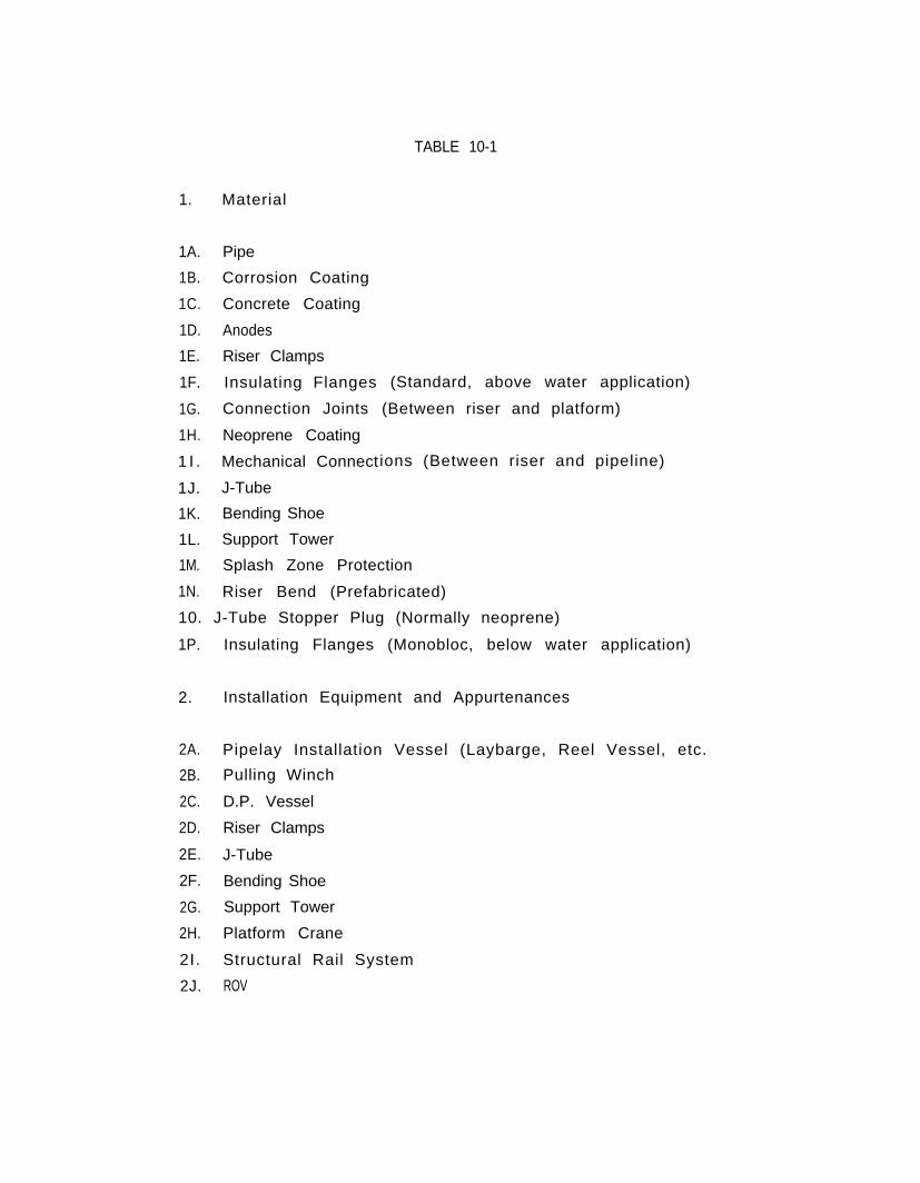
TABLE 10-1
1. Material
1A.
1B.
1C.
1D.
1E.
1F.
1G.
1H.
1 I .
1J.
1K.
1L.
Pipe
Corrosion Coating
Concrete Coating
(Standard, above water application)
(Between riser and platform)
Anodes
Riser Clamps
Insulating Flanges
Connection Joints
Neoprene Coating
Mechanical Connect
J-Tube
Bending Shoe
Support Tower
ions (Between riser and pipeline)
1M. Splash Zone Protection
1N. Riser Bend (Prefabricated)
10. J-Tube Stopper Plug (Normally neoprene)
1P. Insulating Flanges (Monobloc, below water application)
2. Installation Equipment and Appurtenances
2A. Pipelay Installation Vessel (Laybarge, Reel Vessel, etc.
2B. Pulling Winch
2C. D.P. Vessel
2D. Riser Clamps
2E. J-Tube
2F. Bending Shoe
2G. Support Tower
2H. Platform Crane
2I. Structural Rail System
2J. ROV
3. Installation Methods
3A. Field Instal led Riser (Using f loating vessels)
3B. Pre-instal led Riser (Instal led in fabrication yard)
3C. Field Installed Riser (Using deck equipment)