Embed Size (px)
Citation preview

PRICES
• Prices quoted are guaranteed firm for all orders received up until 31st December 2017.• Items marked with a ♦ in description are non-discountable.• Orders placed are accepted subject to the Standard Conditions of Sale.• Orders placed on a deferred delivery basis will be invoiced at the prices ruling at the date of despatch.• There is no minimum order charge.• Prices do not include VAT.
PACKING
• Standard packing is included at no extra cost.• Special packing and labelling can be arranged at an additional cost.
DELIVERY
• The cost of delivery by Standard Carriers to any destination within the UK is FREE OF CHARGE unless otherwise stated.
• Special arrangements for urgent delivery can be made, subject to an additional cost.• Packaged units will incur a delivery charge.
TERMS OF PAYMENT
• Our terms of payment are strictly nett 30 days from end of invoice month.• Visa or MasterCard accepted.
QUALITY
• TLV Euro Engineering have been assessed and approved by DEKRA to ISO 9001:2008 standards. Certificate No. 100212112/1-3
• TLV Co Ltd Kakogawa, Japan have been assessed and approved by Lloyd’s Register Quality Assurance against BS5750: Part 1, 1987 ISO 9001, for the Design and Manufacture of Fluid Control Equipment and Instrumentation for Fluid Flow Measurement CERTIFICATE NO 911058.
• All products are tested prior to despatch from the works.
WARRANTY
• All products have a manufacturer’s guarantee for one year from date of dispatch, following receipt of an order.
TECHNICAL SERVICE AND SUPPORT
• Our office and regional engineers who have considerable experience with the application of all our products are available to discuss technical questions you may have. Please contact 01242 227223 in the first instance.
CERTIFICATION• Please request any required certification at time of placing your order. Prices for certification can be found on Test
and Material Certificates page.
• Please note: Retrospective supply of certificates may not be possible and will incur extra cost.
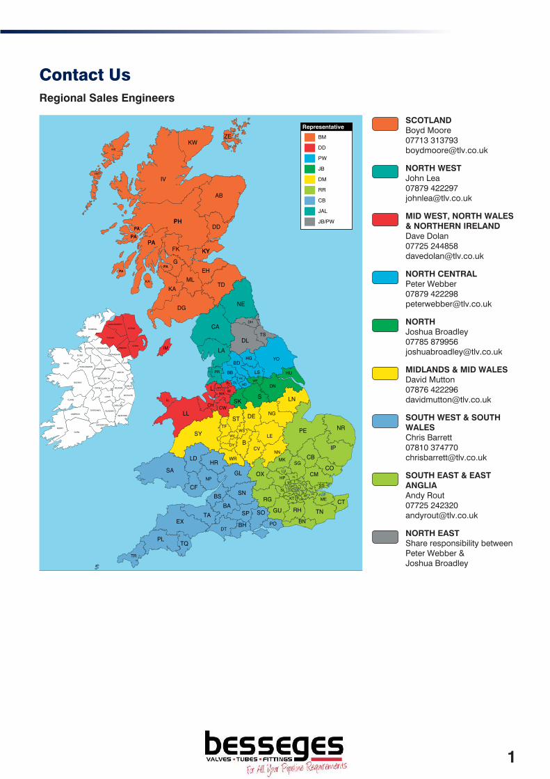
Contact UsRegional Sales Engineers
SCOTLAND Boyd Moore 07713 313793 [email protected]
NORTH WEST John Lea 07879 422297 [email protected]
MID WEST, NORTH WALES & NORTHERN IRELAND Dave Dolan 07725 244858 [email protected]
NORTH CENTRAL Peter Webber 07879 422298 [email protected]
NORTH Joshua Broadley 07785 879956 [email protected]
MIDLANDS & MID WALES David Mutton 07876 422296 [email protected]
SOUTH WEST & SOUTH WALES Chris Barrett 07810 374770 [email protected]
SOUTH EAST & EAST ANGLIA Andy Rout 07725 242320 [email protected]
NORTH EAST Share responsibility between Peter Webber & Joshua Broadley
LONDONDERRY
ANTRIM
DOWN
TYRONE
FERMANAGH ARMAGH
MONAGHAN
LOUTHCAVAN
LEITRIM
SLIGO
MAYO
ROSCOMMONLONGFORD
WESTMEATH
MEATH
DUBLINKILDARE
WICKLOW
CARLOW
WEXFORD
KILKENNY
LAOIS
OFFALY
GALWAY
TIPPERARY
WATERFORD
CLARE
LIMERICK
KERRY
CORK
DONEGAL
KWZE
AL
B
BA
BB
BH
BL
BN
BRBS
AB
EEC
EH
EN
EX
KAKA
KT
KYKY
L M
ME
MK
ML
N
PAPAPAPA
PAPA
PAPAPAPA
PE
PHPH
PL
PO
PR
SA
SE
SG
SK
SLSM
SN
SOSP
SS
ST
SW
SY
G
W
HS
HS
IV
DD
FK
TD
NEDG
DHSR
CA
DLTS
LAYOHG
BD
HU
IM
FY LSWF
DN
LNS
HX
HD
NG
OLWN
WA
CH CWLL
LL
DETF
WSWV LE
NR
IPCB
COCM
NNCV
DY
WRLD HRGL
NPOX
CFHPLU
RG
TA
TR
TQ
DT
GU RH TNCT
WDHA
UB
IG
RM
DA
CR
TW
NWWC
TLV UK
RepresentativeBM
DD
PW
JB
DM
RR
CB
JAL
JB/PW
custom postcode maps by www.gbmaps.com
1

Contents
ABOUT TLV 4
VALVES 5
Stainless Steel Ball Valves . . . . . . . . . . . . . . . . . . . . . . . . . . . . . . . . . . . . . . . . . . . . . . . . . . . . . . . . . . . . . . . . . . . . . . . . . . . . . . . . . . 6
Globe and Bellows Sealed Valves . . . . . . . . . . . . . . . . . . . . . . . . . . . . . . . . . . . . . . . . . . . . . . . . . . . . . . . . . . . . . . . . . . . . . . . . . . . . 7
Bellows Sealed Double Block and Bleed Valve Arrangement . . . . . . . . . . . . . . . . . . . . . . . . . . . . . . . . . . . . . . . . . . . . . . . . . . . . . . 8
Check Valves . . . . . . . . . . . . . . . . . . . . . . . . . . . . . . . . . . . . . . . . . . . . . . . . . . . . . . . . . . . . . . . . . . . . . . . . . . . . . . . . . . . . . . . . . . . . 9
STRAINERS, SIGHT GLASSES AND OTHER PRODUCTS 11
Y-strainers. . . . . . . . . . . . . . . . . . . . . . . . . . . . . . . . . . . . . . . . . . . . . . . . . . . . . . . . . . . . . . . . . . . . . . . . . . . . . . . . . . . . . . . . . . . . . . . 12
Sight Glasses . . . . . . . . . . . . . . . . . . . . . . . . . . . . . . . . . . . . . . . . . . . . . . . . . . . . . . . . . . . . . . . . . . . . . . . . . . . . . . . . . . . . . . . . . . . . 13
Automatic Non-freeze and Blow-Off Valves . . . . . . . . . . . . . . . . . . . . . . . . . . . . . . . . . . . . . . . . . . . . . . . . . . . . . . . . . . . . . . . . . . . . 14
SEPARATORS (CYCLONE TYPE) 15
FILTERS 17
VORTEX FLOWMETERS 19
PRESSURE REDUCING VALVES 21
PRESSURE REDUCING VALVES (WITH BUILT-IN SEPARATOR AND TRAP)Pressure Reducing Valves for Process Steam . . . . . . . . . . . . . . . . . . . . . . . . . . . . . . . . . . . . . . . . . . . . . . . . . . . . . . . . . . . . . . . . . . 22
PRESSURE REDUCING VALVES (WITHOUT SEPARATOR, STRAINER AND TRAP)Pressure Reducing Valves for Steam . . . . . . . . . . . . . . . . . . . . . . . . . . . . . . . . . . . . . . . . . . . . . . . . . . . . . . . . . . . . . . . . . . . . . . . . . 24
PRESSURE REDUCING VALVES (DIRECT ACTING)Direct Acting for Steam and Air. . . . . . . . . . . . . . . . . . . . . . . . . . . . . . . . . . . . . . . . . . . . . . . . . . . . . . . . . . . . . . . . . . . . . . . . . . . . . . 25
SENSORS AND GAUGES 27
SAFETY VALVES 29
AUTOMATIC CONTROL VALVES & CONTROLLERS 31
Pneumatic Control Valves . . . . . . . . . . . . . . . . . . . . . . . . . . . . . . . . . . . . . . . . . . . . . . . . . . . . . . . . . . . . . . . . . . . . . . . . . . . . . . . . . . 32
Electric Control Valves. . . . . . . . . . . . . . . . . . . . . . . . . . . . . . . . . . . . . . . . . . . . . . . . . . . . . . . . . . . . . . . . . . . . . . . . . . . . . . . . . . . . . 34
Self-acting Temperature Regulators . . . . . . . . . . . . . . . . . . . . . . . . . . . . . . . . . . . . . . . . . . . . . . . . . . . . . . . . . . . . . . . . . . . . . . . . . . 35
Surplussing Valves for Steam . . . . . . . . . . . . . . . . . . . . . . . . . . . . . . . . . . . . . . . . . . . . . . . . . . . . . . . . . . . . . . . . . . . . . . . . . . . . . . . 36
Controllers . . . . . . . . . . . . . . . . . . . . . . . . . . . . . . . . . . . . . . . . . . . . . . . . . . . . . . . . . . . . . . . . . . . . . . . . . . . . . . . . . . . . . . . . . . . . . . 37
AIR VENTS AND VACUUM BREAKERS 39
Rapid Initial Air Vents. . . . . . . . . . . . . . . . . . . . . . . . . . . . . . . . . . . . . . . . . . . . . . . . . . . . . . . . . . . . . . . . . . . . . . . . . . . . . . . . . . . . . . 40
Automatic Air Vents . . . . . . . . . . . . . . . . . . . . . . . . . . . . . . . . . . . . . . . . . . . . . . . . . . . . . . . . . . . . . . . . . . . . . . . . . . . . . . . . . . . . . . . 41
Air Vents and Vacuum Breakers . . . . . . . . . . . . . . . . . . . . . . . . . . . . . . . . . . . . . . . . . . . . . . . . . . . . . . . . . . . . . . . . . . . . . . . . . . . . . 42
AIR TRAPS 43
Free Float Air Traps . . . . . . . . . . . . . . . . . . . . . . . . . . . . . . . . . . . . . . . . . . . . . . . . . . . . . . . . . . . . . . . . . . . . . . . . . . . . . . . . . . . . . . . 44
Air Traps for High Viscosity Condensate . . . . . . . . . . . . . . . . . . . . . . . . . . . . . . . . . . . . . . . . . . . . . . . . . . . . . . . . . . . . . . . . . . . . . . 45
STEAM TRAPS 47
APPLICATION GUIDE . . . . . . . . . . . . . . . . . . . . . . . . . . . . . . . . . . . . . . . . . . . . . . . . . . . . . . . . . . . . . . . . . . . . . . . . . . . . . . . . . . . . . . . 48
FREE FLOAT STEAM TRAPS . . . . . . . . . . . . . . . . . . . . . . . . . . . . . . . . . . . . . . . . . . . . . . . . . . . . . . . . . . . . . . . . . . . . . . . . . . . . . . . . . 49
J-Series . . . . . . . . . . . . . . . . . . . . . . . . . . . . . . . . . . . . . . . . . . . . . . . . . . . . . . . . . . . . . . . . . . . . . . . . . . . . . . . . . . . . . . . . . . . . . . . . . 50
SJ-Series. . . . . . . . . . . . . . . . . . . . . . . . . . . . . . . . . . . . . . . . . . . . . . . . . . . . . . . . . . . . . . . . . . . . . . . . . . . . . . . . . . . . . . . . . . . . . . . . 51
JH-Series . . . . . . . . . . . . . . . . . . . . . . . . . . . . . . . . . . . . . . . . . . . . . . . . . . . . . . . . . . . . . . . . . . . . . . . . . . . . . . . . . . . . . . . . . . . . . . . 52
S-Series. . . . . . . . . . . . . . . . . . . . . . . . . . . . . . . . . . . . . . . . . . . . . . . . . . . . . . . . . . . . . . . . . . . . . . . . . . . . . . . . . . . . . . . . . . . . . . . . . 55
SH-Series . . . . . . . . . . . . . . . . . . . . . . . . . . . . . . . . . . . . . . . . . . . . . . . . . . . . . . . . . . . . . . . . . . . . . . . . . . . . . . . . . . . . . . . . . . . . . . . 56
Large Capacity Traps . . . . . . . . . . . . . . . . . . . . . . . . . . . . . . . . . . . . . . . . . . . . . . . . . . . . . . . . . . . . . . . . . . . . . . . . . . . . . . . . . . . . . . 58
THERMODYNAMIC STEAM TRAPS . . . . . . . . . . . . . . . . . . . . . . . . . . . . . . . . . . . . . . . . . . . . . . . . . . . . . . . . . . . . . . . . . . . . . . . . . . . . 59Disc Type Steam Traps . . . . . . . . . . . . . . . . . . . . . . . . . . . . . . . . . . . . . . . . . . . . . . . . . . . . . . . . . . . . . . . . . . . . . . . . . . . . . . . . . . . . 60
THERMOSTATIC STEAM TRAPS . . . . . . . . . . . . . . . . . . . . . . . . . . . . . . . . . . . . . . . . . . . . . . . . . . . . . . . . . . . . . . . . . . . . . . . . . . . . . . 63Thermostatic Steam Traps. . . . . . . . . . . . . . . . . . . . . . . . . . . . . . . . . . . . . . . . . . . . . . . . . . . . . . . . . . . . . . . . . . . . . . . . . . . . . . . . . . 64
Temperature Control Traps . . . . . . . . . . . . . . . . . . . . . . . . . . . . . . . . . . . . . . . . . . . . . . . . . . . . . . . . . . . . . . . . . . . . . . . . . . . . . . . . . 65
CLEAN STEAM TRAPS / AIR VENTS / VACUUM BREAKERS . . . . . . . . . . . . . . . . . . . . . . . . . . . . . . . . . . . . . . . . . . . . . . . . . . . . . . . . 66
QUICKTRAPS . . . . . . . . . . . . . . . . . . . . . . . . . . . . . . . . . . . . . . . . . . . . . . . . . . . . . . . . . . . . . . . . . . . . . . . . . . . . . . . . . . . . . . . . . . . . . 67
CONDENSATE RECOVERY EQUIPMENT 69
PowerTrap® (Mechanical Pump with Built-in Trap). . . . . . . . . . . . . . . . . . . . . . . . . . . . . . . . . . . . . . . . . . . . . . . . . . . . . . . . . . . . . . 70
PowerTrap® (Mechanical Pump) . . . . . . . . . . . . . . . . . . . . . . . . . . . . . . . . . . . . . . . . . . . . . . . . . . . . . . . . . . . . . . . . . . . . . . . . . . . . 71
Packaged Pump Systems . . . . . . . . . . . . . . . . . . . . . . . . . . . . . . . . . . . . . . . . . . . . . . . . . . . . . . . . . . . . . . . . . . . . . . . . . . . . . . . . . . 72
VALVES 5
STRAINERS, SIGHT GLASSES AND OTHER PRODUCTS 11
SEPARATORS (CYCLONE TYPE) 15
FILTERS 17
VORTEX FLOWMETERS 19
PRESSURE REDUCING VALVES 21
SENSORS AND GAUGES 27
SAFETY VALVES 29
AUTOMATIC CONTROL VALVES & CONTROLLERS 31
AIR VENTS AND VACUUM BREAKERS 39
AIR TRAPS 43
STEAM TRAPS 47
CONDENSATE RECOVERY EQUIPMENT 69
2

Contents
PACKAGED SOLUTIONS 73
HeatPacks. . . . . . . . . . . . . . . . . . . . . . . . . . . . . . . . . . . . . . . . . . . . . . . . . . . . . . . . . . . . . . . . . . . . . . . . . . . . . . . . . . . . . . . . . . . . . . . 73
Vacuumiser. . . . . . . . . . . . . . . . . . . . . . . . . . . . . . . . . . . . . . . . . . . . . . . . . . . . . . . . . . . . . . . . . . . . . . . . . . . . . . . . . . . . . . . . . . . . . . 74
Steam Compressor . . . . . . . . . . . . . . . . . . . . . . . . . . . . . . . . . . . . . . . . . . . . . . . . . . . . . . . . . . . . . . . . . . . . . . . . . . . . . . . . . . . . . . . 75
MANIFOLDS 77
MAINTENANCE INSTRUMENTS 79
CONSULTATION AND AUDITING SERVICES 81
STEAM AND CONDENSATE TRAINING SEMINARS 82
DOCUMENTATION 83
APPLICATION DRAWINGS 85
FAQS 104
TABLES AND DATA 107
Steam Table . . . . . . . . . . . . . . . . . . . . . . . . . . . . . . . . . . . . . . . . . . . . . . . . . . . . . . . . . . . . . . . . . . . . . . . . . . . . . . . . . . . . . . . . . . . . . 107
Steam Capacity (kg/h) in a pipe based on Velocities. . . . . . . . . . . . . . . . . . . . . . . . . . . . . . . . . . . . . . . . . . . . . . . . . . . . . . . . . . . . . 108
PACKAGED SOLUTIONS 73
MANIFOLDS 77
MAINTENANCE INSTRUMENTS 79
CONSULTATION AND AUDITING SERVICES 81
STEAM AND CONDENSATE TRAINING SEMINARS 82
DOCUMENTATION 83
APPLICATION DRAWINGS 85
FAQS 104
TABLES AND DATA 107
3

Corporate Profi le
About TLV
Company HistorySince its founding over a half century ago, TLV’s goal has been to produce dependable, long-lasting steam traps. One early outstanding success was the A3, a thermodynamic steam trap offering an amazing 10 times the durability of previous products.
Behind the A3 was the concept of the ‘Trouble Less Valve’, from which the company name originated. From this solid foundation, the line of products and services has expanded until now, more than 60 years later, TLV has become a Steam Specialist Company - a recognised leader in the steam-engineering fi eld.
Worldwide service and supportTLV is internationally established, with companies in 12 countries. A network of over 100 distributors in more than 50 countries enables the provision of engineering support in any part of the world at any time.
TLV plays a leading role in the promotion of effi cient energy systems and increased environmental conservation on a worldwide scale through its original products and services.
InnovationTLV maintains a level of craftsmanship that surpasses customer expectations. To achieve this, research and development does not imitate present and industry standard designs, but instead completely re-engineers concepts and ideas. With the principle ‘to design and build only patented products’ at its core, TLV currently holds over 2000 patents (including pending items). This number is itself a testament to originality.
TLV Co., Ltd. received ASME Sect. III (Rules for Construction of Nuclear Facility Components) certifi cation for its traps, strainers, and other miscellaneous items and parts, effective Nov. 12, 2010
4

VA
LV
ESValves
Presenting a variety of valves for use on steam, air, water, etc.
Stainless Steel Ball Valves
Ball valves suitable for steam lines.
Globe and Bellows Sealed Valves
Bellows sealed valves with a no-leak gland packing seal.
Check Valves
Check valves suitable for steam and other medium.
Benefits and FeaturesDesigned for a tight seal and excellent durability for use on steam lines.
5

Stainless Steel Ball ValvesV
ALV
ES Valves
Stainless Steel Ball ValvesPresenting ball valves suitable for steam, water and air lines.
Operating Pressure Range: 0 - 10 barg
Operating Temperature Range: 0 - 185 °C
Benefits and FeaturesHigh Cost Performance Ratio
Long Service Life
All stainless steel for excellent resistance to rust, and the carbon-Teflon valve seat provides superior durability and resistance to pressure.
BV1All stainless steel full bore ball valve of 3-piece design for steam, water, air, liquids and gases.
BV6Stainless steel wafer-type ball valve with full bore for steam, water, air, other fluids and gases. Maintenance free.
BV5111♦
Stainless steel full bore ball valve of 3-piece design for steam.
BV4290♦
Stainless steel full bore flanged PN16 (PN40 also available) ball valve of 2-piece design.
ModelMax Operating Pressure (barg)
Max Operating Temperature (°C)
Max Allowable Pressure (barg)
Max Allowable Temperature (°C)
Body Material
BV1 10 185 10 185 Stainless Steel
BV6 10 185 10 185 Stainless Steel
BV5111 10 185 10 200 Stainless Steel
BV4290 10 185 10 200 Stainless Steel
Model Body MaterialConnection
Type1/2"
DN153/4"
DN201"
DN251 1/4" DN32
1 1/2" DN40
2" DN50
2 1/2" DN65
3" DN80
4" DN100
BV1 Stainless Steel Screwed 57.00 68.50 91.50 113.50 176.50 234.00 523.00 763.50 -
BV6 Stainless Steel Wafer-type 123.00 155.00 190.00 259.50 375.00 456.00 555.50 714.00 948.00
BV5111 Stainless Steel Screwed 27.00 34.00 43.00 61.00 89.00 123.00 - - -
BV4290 Stainless Steel Flanged 116.00 142.00 179.00 237.00 298.50 421.00 613.00 785.50 1,161.50
6

Globe and Bellows Sealed Valves
VA
LV
ESValves
Globe and Bellows Sealed ValvesPresenting bellows sealed valves with a no-leak gland locking seal or gland sealed valves.
Operating Pressure Range: 0 - 40 barg
Operating Temperature Range: 0 - 400 °C
Benefits and FeaturesMaintenance-free at stem gland
Bellows-type gland prevents leakage to the outside. No need to tighten or replace the gland packing.
1029♦ Bronze Gland Sealed Globe Valve suitable for saturated steam up to 14 barg, water, oil and air.
BE3LCompact forged steel globe valve for steam, hot water, heat transfer fluid, etc. Suitable for use with small-process equipment.
BE8HTwo port maintenance-free bellows sealed globe valve. Available in cast iron (BE8H-16), S.G. iron (BE8H-25), or cast steel (BE8H-40).
BOA-H♦
Two port maintenance-free bellows sealed globe valve. Available in cast iron (BOA-H-16), S.G. iron (BOA-H-25), or cast steel (BOA-H-40).
ModelMax Operating
Pressure (barg) – Sat. SteamMax Operating
Temperature (°C)Max Allowable
Pressure (barg)Max Allowable
Temperature (°C)Body Material
1029 14.0 198 @ 14barg 32 @ 100°C 198 Bronze
BE3L 50.0 400 57 427 Carbon Steel
BE8H-16 12.8 300 @9.6 barg 16 @ 120°C 300 Cast Iron
BE8H-25 22.5 350 @17.5barg 25 @ 120°C 350 S.G. Iron
BE8H-40 30.4 400 @23.8barg 40 @ 150°C 400 Cast Steel
BOA-H-16 12.8 300 @9.6 barg 16 @ 120°C 300 Cast Iron
BOA-H-25 22.5 350 @17.5barg 25 @ 120°C 350 S.G. Iron
BOA-H-40 30.4 400 @23.8barg 40 @ 150°C 400 Cast Steel
Model Body MaterialConnection
Type1/2"
DN153/4"
DN201"
DN251 1/4" DN32
1 1/2" DN40
2" DN50
2 1/2" DN65
3" DN80
4" DN100
5" DN125
6" DN150
1029 Bronze Screwed 31.00 44.00 61.00 85.00 117.50 180.50 - - - - -
BE3L Carbon Steel Screwed/SW 124.00 132.50 148.00 - 292.00 341.50 - - - - -
BE8H-16 Cast Iron Flanged 69.00 74.00 84.00 97.50 111.00 128.00 178.50 227.50 306.00 470.50 593.00
BE8H-25 S.G. Iron Flanged 104.50 110.50 123.00 146.00 167.50 195.00 267.00 341.50 526.00 799.00 1,009.00
BE8H-40 Cast Steel Flanged 144.00 152.00 162.50 218.00 273.00 345.00 473.00 632.00 801.50 1,259.00 1,437.00
BOA-H-16 Cast Iron Flanged 88.50 94.00 112.00 131.00 145.50 172.00 225.00 280.00 358.00 546.00 691.00
BOA-H-25 S.G. Iron Flanged 154.50 163.50 190.00 226.00 268.50 322.50 395.50 517.50 683.50 956.00 1,346.00
BOA-H-40 Cast Steel Flanged 272.00 282.00 288.00 388.50 429.50 472.00 735.00 1,004.00 1,256.00 1,744.00 2,160.50
7
Based on Bellows Sealed Valves*V
ALV
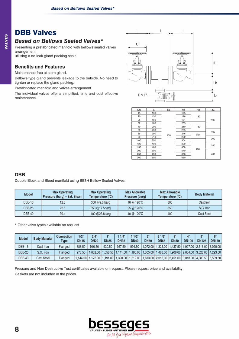
ES DBB Valves
Based on Bellows Sealed Valves*Presenting a prefabricated manifold with bellows sealed valves arrangement, utilising a no-leak gland packing seals.
Benefits and FeaturesMaintenance-free at stem gland.
Bellows-type gland prevents leakage to the outside. No need to tighten or replace the gland packing.
Prefabricated manifold and valves arrangement.
The individual valves offer a simplified, time and cost effective maintenance.
DBBDouble Block and Bleed manifold using BE8H Bellow Sealed Valves.
ModelMax Operating
Pressure (barg) – Sat. SteamMax Operating
Temperature (°C)Max Allowable
Pressure (barg)Max Allowable
Temperature (°C)Body Material
DBB-16 12.8 300 @9.6 barg 16 @ 120°C 300 Cast Iron
DBB-25 22.5 350 @17.5barg 25 @ 120°C 350 S.G. Iron
DBB-40 30.4 400 @23.8barg 40 @ 120°C 400 Cast Steel
* Other valve types available on request.
Model Body MaterialConnection
Type1/2"
DN153/4"
DN201"
DN251 1/4" DN32
1 1/2" DN40
2" DN50
2 1/2" DN65
3" DN80
4" DN100
5" DN125
6" DN150
DBB-16 Cast Iron Flanged 888.50 910.50 930.50 957.50 994.50 1,072.00 1,325.00 1,437.50 1,927.00 2,516.00 3,020.00
DBB-25 S.G. Iron Flanged 978.50 1,002.00 1,058.50 1,141.50 1,190.00 1,305.00 1,483.00 1,906.00 2,604.00 3,526.00 4,293.50
DBB-40 Cast Steel Flanged 1,144.50 1,172.00 1,191.00 1,390.00 1,512.00 1,613.00 2,013,00 2,451.00 3,018.00 4,883.50 5,509.50
Pressure and Non Destructive Test certificates available on request. Please request price and availability.
Gaskets are not included in the prices.
DN L LB H1 H2 øC15 130
130
175130
10020 150 17825 160 18432 180 205
15040 200 21050 230 235
16065 290 246
20080 310 282
200100 350 304
250
125 400 390250
150 480 408200 600 570
400250 730 606300 850 660
8

Check Valves
VA
LV
ESValves
Check ValvesCheck valves for steam and other fluids. Automatic valves for preventing backflow.
Operating Pressure Range: 0 - 40 barg
Operating Temperature Range: -100 - 400 °C
Benefits and FeaturesCheck valves with disc and spring construction that assures performance with installation in either vertical or horizontal pipelines with reliable backflow prevention.
There are no restrictions on installation orientation (1039 horizontal only). After the valve has closed, it opens again at the slightest pressure differential.
TLV’s unique centre-guided disc (CK3MG, CKF3MG, and CKF3RG) offers greater durability.
CK3M(G) / CK3TCoil spring, disc type check valve. Screwed type. Stainless Steel with brass option on CK3M. Available with metal seat (CK3M) or Teflon seat (CK3T).
CKF3M(G) / CKF3R(G)Coil spring, disc type check valve. Between flanges, wafer type. Stainless steel with metal seat (CKF3M) or FPM seat (CKF3R). Compatible with almost all flange specifications (ASME, BS, DIN, JIS).
SR 20.40Large nominal diameter, wafer type, stainless steel check valve.
1039♦
Budget bronze horizontal lift type check valve. Body rated to PN32. Screwed connections. Not suitable for vertical installations.
ModelMax Operating Pressure (barg)
Max Operating Temperature (°C)
Max Allowable Pressure (barg)
Max Allowable Temperature (°C)
Body Material
CK3M(G) 21 220 21 (G – 32) 220 (G – 350) Stainless Steel
CK3M 10 220 10 220 Brass
CK3T 16 185 21 220 Stainless Steel
CKF3M(G) 30 350 30 350 Stainless Steel
CKF3R(G) 16 150 30 350 Stainless Steel
SR 20.40 35 @ 200°C 400 @ 25barg 40 400 Stainless Steel
1039 32 @ 100°C 198 @ 14barg 32 198 Bronze
ModelBody
MaterialSeat
MaterialConnection
Type1/2"
DN153/4"
DN201"
DN251 1/4" DN32
1 1/2" DN40
2" DN50
2 1/2" DN65
3" DN80
4" DN100
CK3M(G)* Stainless Steel Stainless Steel Screwed 87.15 94.50 118.65 247.00 292.00 356.00 - 676.00 -
CK3M Brass Brass Screwed 82.00 87.00 108.00 209.00 239.50 299.00 - - -
CK3T Stainless Steel Flourine Resin Screwed 76.00 94.50 126.00 209.00 237.00 287.00 - - -
CKF3M(G) Stainless Steel Stainless Steel Wafer 76.00 87.00 101.00 120.00 130.50 153.50 246.00 271.00 356.00
CKF3R(G) Stainless SteelFlourine Rubber
Wafer 91.50 101.00 119.00 143.00 157.50 176.50 - - -
SR 20.40 Stainless Steel Wafer - - - - - - 335.00 368.00 567.00
1039 Bronze Brass Screwed 25.50 38.00 54.00 72.00 85.00 136.00 - - -
* (G) type: centre guided valve disc for sizes >1”
9

ST
RA
INE
RS
SIG
HT
GLA
SS
ES
A
ND
OT
HE
R P
RO
DU
CT
S
Strainers, Sight Glasses and Other ProductsPresenting steam equipment including strainers, sight glasses, non-freeze valves and a variety of other ancillary products – used in the steam trap periphery.
Y-strainers
For removing dirt and scale from inside piping.
Sight Glasses
For visually monitoring the flow of fluids from the outside of the piping.
Automatic Non-freeze and Blow-off Valves
Miscellaneous valves for using with steam systems.
Benefits and Features- Option of automatic non-freeze valve or blow-off valve combined with the trap body can be manufactured
(consult with TLV when placing trap order)
- Sight glasses feature a PTFE (fluorine resin) gasket for easy disassembly and maintenance
Application Areas- Automatic non-freeze valve - protects steam traps from problems caused by frozen condensate
- Blow-off valve - blows scale out of steam traps
Y-strainers
Sight Glasses
Automatic Non-freeze and Blow-off Valves
11

Y-strainersS
TR
AIN
ER
S S
IGH
T G
LA
SS
ES
A
ND
OT
HE
R P
RO
DU
CT
S
Strainers, Sight Glasses and Other ProductsY-strainersFor removing dirt and scale from the steam and other fluid flow inside piping.
Operating Pressure Range: 0 - 40 barg
Operating Temperature Range: 0 - 400 °C
Benefits and FeaturesEasy to Use
Compact size requires very little installation space. Simple construction makes maintenance easy.
Stable Operation of Various Types of Equipment
Double-layer screen catches even tiny particles of dirt.
Large flow surface area results in minimal pressure drop, so there is no effect on equipment operation.
Y3Stainless steel screwed Y-type strainer suitable for installation in front of a trap or reducing valve. For use with steam, water and oil.
Y8FFlanged Y-type strainer. Screen has aperture size 1.0mm (DN15 – 20), 1.25mm (DN25-65) or 1.6mm (DN80-200)
SF-320Stainless Steel flanged Y-type strainer suitable for installation in front of a trap or reducing valve.
Model Mesh SizeMax Operating Pressure (barg)
Max Operating Temperature (°C)
Max Allowable Pressure (barg)
Max Allowable Temperature (°C)
Body Material
Y3 60 21 220 21 220 Stainless Steel
Y8F-16 See text 16 @ 120°C 300 @13 barg 16 300 Cast Iron
Y8F-25 See text 25 @ 120°C 350 @12barg 25 350 S.G. Iron
Y8F-40 See text 40 @ 50°C 400 @ 23.8barg 40 400 Cast Steel
SF-320 14 30.5 @ 120°C 300 @ 21barg 60 450 Stainless Steel
*for >2” versions
Model Body MaterialConnection
Type1/2"
DN153/4"
DN201"
DN251 1/4" DN32
1 1/2" DN40
2" DN50
2 1/2" DN65
3" DN80
4" DN100
5" DN125
6" DN150
Y3 Stainless Steel Screwed 47.50 62.00 74.50 102.00 125.00 196.50 - - - - -
Y8F-16 Cast Iron Flanged 33.00 36.00 37.00 43.00 56.00 58.00 92.50 119.00 166.00 249.00 338.00
Y8F-25 S.G. Iron Flanged 60.00 64.00 68.50 92.50 125.00 143.00 191.00 234.00 386.50 413.00 551.50
Y8F-40 Cast Steel Flanged 94.50 116.50 129.00 163.00 200.50 238.50 250.00 370.00 560.00 756.00 1,022.00
SF-320 Stainless Steel Flanged 280.50 316.00 365.50 422.00 491.50 597.50 915.50 1,309.50 1,711.50 2,551.50 3,438.00
12

Sight Glasses
ST
RA
INE
RS
SIG
HT
GLA
SS
ES
A
ND
OT
HE
R P
RO
DU
CT
S
Strainers, Sight Glasses and Other ProductsSight GlassesPresenting sight glasses for visually monitoring the flow of fluids from the outside of the piping.
Operating Pressure Range: 0 - 25 barg
Operating Temperature Range: 0 - 450 °C
Benefits and FeaturesEasy to Use
Ball movement indicates flow status, which gives superior visibility. Use of PTFE (fluorine resin) gasket results in superior maintainability.
T5N Sight glass for use up to 10 barg/120 °C. For use on water, air and steam.
T8N / TF8NSight glass for use up to 16 barg/200 °C. For use on water, air and steam.
SG18 / SG18ESight glass in straightaway form with body made of cast steel. Also available in stainless steel (SG18E).
ModelMax Operating Pressure (barg)
Max Operating Temperature (°C)
Max Allowable Pressure (barg)
Max Allowable Temperature (°C)
Body Material
T5N 10 120 10 120 Cast Iron
T8N 16 200 16 200 Cast Iron
TF8N 16 200 16 200 Cast Iron
SG18 25 CWP 450 @ 9.1barg 25 450 Cast Steel
SG18E 25 CWP 300 @ 14.2barg 25 300 Stainless Steel
Model Body Material Connection Type1/2"
DN153/4"
DN201"
DN251 1/2" DN40
2" DN50
2 1/2" DN65
3" DN80
4" DN100
T5N Cast Iron Screwed 163.00 164.00 169.00 199.50 210.00 - - -
T8N Cast Iron Screwed 94.50 103.00 106.00 153.50 167.00 - - -
TF8N Cast Iron Flanged 147.00 153.50 178.50 204.00 229.00 - - -
SG18 Cast Steel Flanged 395.00 405.00 468.00 545.00 720.00 747.00 1,025.00 1,100.00
SG18E Stainless Steel Flanged 297.00 383.00 531.00 1,077.00 1,130.00 - - -
13

Automatic Non-freeze and Blow-Off ValvesS
TR
AIN
ER
S S
IGH
T G
LA
SS
ES
A
ND
OT
HE
R P
RO
DU
CT
S
Strainers, Sight Glasses and Other ProductsAutomatic Non-freeze and Blow-Off Valves
Operating Pressure Range: 0 - 65 barg
Operating Temperature Range: 0 - 425 °C
Benefits and FeaturesAutomatic Non-Freeze Valve
Automatically removes condensate from inside the trap to prevent damage to the trap from freeze-up of residual condensate during shut-down. Compact size makes for simple installation. No adjustment necessary as it remains closed during equipment operation, automatically opening to discharge condensate using gravity after the shut-off of equipment.
Blow-Off Valve
Simple to use blow-off valve which utilises the steam pressure to clear debris out of steam trap. Simple unscrewing action of the collar to operate the valve.
Non-Freeze ValveNF6Non-freeze valve for draining residual condensate from traps to prevent steam trap damage caused by freeze-up. Built-in screen protects the valve from trouble caused by clogging.
Blow-Off ValveBD2Stainless steel valve utilises a steam trap’s internal pressure to blow any condensate, oil, dirt or scale inside the steam trap out to atmosphere. Simple design, compact and light weight. Easy to use and maintain.
ModelMax Operating Pressure (barg)
Max Operating Temperature (°C)
Max Allowable Pressure (barg)
Max Allowable Temperature (°C)
Body Material
NF6 20 220 20 220 Brass
BD2 65 425 65 425 Stainless Steel
Model Body MaterialConnection
Type1/4" DN8
NF6 Brass Screwed 78.00
BD2 Stainless Steel Screwed 62.00
14

SE
PA
RA
TO
RS
Separators (Cyclone Type)
Presenting inline installation type steam and air separators.
Operating Pressure Range: 0 - 40 barg (higher pressures on special applications)
Operating Temperature Range: 0 - 400 °C
Benefits and FeaturesA separator that forcibly separates out the condensate generated and entrained in pipelines of steam or air.
All models equipped with a cyclone separator that demonstrates a remarkably high 98% separation efficiency. The integral trap, which is included with the DC3 variants, is a free float type that uses three-point seating, with continuous discharge and a tight seal.
The separator supplies high-quality steam or air from which the condensate has been removed, which has a direct connection to productivity and product quality.
DC3SCyclone separator (with integral strainer and steam trap) for steam.
DC3ACyclone separator (with integral strainer and drain trap) for air.
DC7Can be used with steam, air, and non hazardous gasses. Stainless steel welded construction. Cyclone separator for use with separate steam trap.
Model BZCyclonic separator provides high-quality dry steam. Flanged connections for the majority of specifications.
ModelMax Operating Pressure (barg)
Max Operating Temperature (°C)
Max Allowable Pressure (barg)
Max Allowable Temperature (°C)
Body Material
DC3S 21 220 21 220 Ductile Cast Iron
DC3A 10 100 10 100 Ductile Cast Iron
DC7 25 300 25 300 Stainless Steel
BZ 40 400 40 400 Cast Steel
BZ 40 400 40 400 Stainless Steel
Model Body Material Connection Type1/2"
DN153/4"
DN201"
DN251 1/2" DN40
2" DN50
2 1/2" DN65
3" DN80
4" DN100
DC3S Ductile Cast Iron Flanged 837.00 844.00 940.00 1,156.00 1,638.00 - - -
Ductile Cast Iron Screwed 737.00 737.00 848.50 - - - - -
DC3A Ductile Cast Iron Flanged 965.00 973.50 1,028.00 1,205.50 1,637.00 3,846.00 3971.00 5,559.00
Ductile Cast Iron Screwed 828.50 828.50 915.50 - - - - -
DC7 Stainless Steel Screwed 462.00 476.00 668.00 780.00 1,363.00 - - -
Stainless Steel Flanged 970.00 1,069.00 1,109.00 1,482.50 1,641.00 - - -
BZ Cast Steel As required PoR PoR PoR PoR PoR PoR PoR PoR
BZ Stainless Steel As required PoR PoR PoR PoR PoR PoR PoR PoR
Larger sizes are available for the Model BZ – Prices on request
15

FIL
TE
RS
Filters
Presenting filters for the production of high quality steam and clean steam generation.
Operating Pressure Range: 0 - 16 barg
Operating Temperature Range: -50 - 200 °C
Benefits and FeaturesIn regular piping, steam carries large quantities of entrained material. With the following filters, improved heating efficiency and product quality can be obtained by removing dirt and scale. Ideal for food bio-related industries and other applications requiring high quality steam.
The SF1 incorporates a cyclone separator which separates out condensate and dirt, which greatly reduces clogging of the filter and lengthens the time between cleanings and parts’ replacement cycles.
All stainless steel, with a compact, light-weight design. Easy to clean and inspect.
SF1Separator and filter for use on steam and other gases (non-toxic, non-flammable). The cyclone separator separates out and removes the condensate, which allows for the supply of dry steam, so no wet spots occur. Filter available in a range of mesh sizes. 5-layer sintered wire mesh filter is reusable and easy to clean.
P-EGS Series♦
The P-EGS filter designed for use in critical application areas of steam filtration. High quality stainless steels, highly-polished housing surfaces and the avoidance of corners and edges form the basis for the optimised flow design of the P-EGS housing series. Flow is free of turbulence minimising pressure losses through the filter. Suitable for clean steam generation
ModelFilter Porosity
µmMax Operating Pressure (barg)
Max Operating Temperature (°C)
Max Allowable Pressure (barg)
Max Allowable Temperature (°C)
Body Material
SF1 0.5, 2, 5, 10 6 / 10* 165 / 185** 6 / 10* 165/ 185** Stainless Steel
P-EGS Series 1, 5 7 200 16 200 Stainless Steel* Depending on body clamp used ** Depending on the type used
Model Body MaterialConnection
TypeFilter
Porosity1/2"
DN153/4"
DN201"
DN251 1/4" DN32
1 1/2" DN40
2" DN50
2 1/2" DN65
3” DN80
SF1
Stainless Steel Screwed/SW 2, 5, 10µm 2,354.00 2,354.00 2,630.00 - 3,375.00 5,155.00 - -
Stainless Steel Screwed/SW 0.5µm 2,725.00 2,725.00 2,990.50 - 4,387.00 5,703.00 - -
Stainless Steel Flanged 2, 5, 10µm 2,505.00 2,632.00 3,089.00 - 4,222.00 5,673.00 - -
P-EGSStainless Steel Screwed 1µm PoR PoR PoR PoR PoR PoR PoR PoR
Stainless Steel Flanged 1µm PoR PoR PoR PoR PoR PoR PoR PoR
Filter Porosity
Suggested filter element ratings:
0.5 µm min – Pharmaceutical grade steam
2.0 µm min – Culinary (Clean steam) grade steam
10.0 µm – General applications.
17

VO
RT
EX
FLO
WM
ET
ER
S
Vortex FlowmetersPresenting vortex flowmeters and flow computers. Measures the flow rates of a variety of fluids, including steam, air and water.
Operating Pressure Range: 0 - 49.6 barg
Operating Temperature Range: -200 °C - 400 °C
Benefits and FeaturesHigh performance vortex flowmeter with robust sensor for highly accurate volume or mass flow measurements of gasses, liquids, saturated and superheated steam. Measures flow by means of the regular vortices (von Karman vortex) generated downstream of an object as fluid flows around the object.
The EF200 flowmeter requires no maintenance as it has no moving parts and experiences no zero point drift. Simple to install with minimum number of components. Range of accessories available to suit all applications.
*Limited by freezing point of liquid.
EF200Integrated temperature sensor, automatically corrects for mass flow rate and is equipped with a digital readout display. Capable of simultaneous pulse (interval) and analogue (instantaneous) output.
Ingress resistant to IP 67 (NEXA 4X)
Recommend pipe spacing for flow meter.
ModelMax Operating Pressure (barg)
Max Operating Temperature (°C)
Max Allowable Pressure (barg)
Max Allowable Temperature (°C)
Body Material
EF200 0 – 49.6 400 49.6 400 Cast Stainless Steel
Conditioner Plate - - 50 400 Stainless Steel
Model Body MaterialConnection
Type1/2"
DN151"
DN251 1/2" DN40
2" DN50
3" DN80
4" DN100
6" DN150
EF200 Stainless Steel Wafer 3,306.50 3,306.50 3,493.00 3,493.00 3,675.00 3,802.00 4,929.00
Conditioner Plate Stainless Steel Wafer 222.00 271.00 273.00 276.00 309.00 380.00 523.00
Remote computer - - 501.00
19

PR
ES
SU
RE
RU
DC
ING
VA
LV
ES
Pressure Reducing ValvesSummaryPresenting pressure reducing valves for steam. A wide assortment of models are available, including pilot operated models, direct-acting models and models with integral separators and steam traps.
Operating inlet Pressure Range: 1 - 21 barg
Operating Temperature Range: 0 - 220 °C
Pressure Reducing Valves (with built-in strainer, separator and trap) Presenting pilot operated pressure reducing valves with built-in strainer, separator and trap, whose features result to supply dry steam or air with stable secondary pressure, improve product quality and/or heat efficiency. Local set or remote set types are available.
Pressure Reducing Valves (without built-in separator and trap) Presenting pilot operated pressure reducing valves to supply steam or air with stable secondary pressure for general use. Local set or remote set types are available.
Pressure Reducing Valves (Direct Acting) Compact, light-weight direct-acting pressure reducing valves.
Benefits and FeaturesValves for controlling steam pressure. They provide the prescribed pressure even when flow rates fluctuate. Selection can be made from among a wide assortment of models — including pilot operated and direct-acting models and models with integral separators and steam traps — to suit the objective or application.
The high precision pressure reducing valves for process applications employ a separator with steam trap and shock- absorbing spherical piston to yield a superior flow rate characteristic.
The basic configuration of the reducing valves for air is identical to that of those for steam, and therefore also yields a superior flow rate characteristic.
Application AreasFor the supply of dry steam with no entrained condensate at a stable pressure - Pressure reducing valves for steam process applications
For equipment such as compact steam heating equipment - Compact pressure reducing valves for steam
For steam transport lines, heaters, etc. - Multi-purpose pressure reducing valves for steam.
21

Pressure Reducing Valves for Process SteamP
RE
SS
UR
E R
ED
UC
ING
VA
LV
ES
Pressure Reducing Valves (Pilot Operated)(With Built-in Separator, Strainer and Trap)Pressure Reducing Valves for Process SteamCOSPECT® - High precision pressure reducing valves with built-in separator & trap.
Benefits and FeaturesProduct features a built-in Super Cyclonic Effects Separator, which has 98% condensate separation efficiency. Condensate entrained in the steam is separated out, and a strainer further removes any scale. The condensate that is separated out is quickly removed through the built-in free float trap. This improvement in the quality of the steam itself also results in an improvement to the heat transfer of the steam. All internal major components are made of stainless steel to prevent rust.
Supplies steam at a stable pressure.Accuracy of pressure reducing valve’s secondary set pressure is within ± 0.1 bar. Even if the steam load to the equipment or the primary pressure at the pressure reducing valve changes, the Shock-absorbing Spherical Piston supplies steam at a constant pressure in order to maintain the temperature of the steam used as the heating source.
COS-3Pressure reducing valve for use on low pressures up to a maximum operating pressure of 3 barg. Pressure adjustment range: 0.1 – 0.5 barg.
COS-16Pressure reducing valve for use up to a maximum operating pressure of 16 barg. Pressure adjustment range: 0.3 – 13.4 barg.
COS-21Pressure reducing valve for use on high pressures up to a maximum operating pressure of 21 barg. Pressure adjustment range: 5.5 – 17.6 barg.
SCOS-16Pressure reducing valve specialised for low flow rates, the body has an extremely compact design. Pressure adjustment range: 0.3 – 13.4 barg.
ModelMax Operating Pressure (barg)
Max Operating Temperature (°C)
Max Allowable Pressure (barg)
Max Allowable Temperature (°C)
Body Material
COS-3/16 3, 16 200 13 220 Cast Iron
COS-3/16/21 3, 16, 21 220 21 220 Ductile Cast Iron
COS-3/16/21E 3, 16, 21 220 21 220 Cast Stainless Steel
COS-16G 16 220 21 220 Carbon Steel
SCOS-16 16 220 16 220 Bronze
Model Body MaterialConnection
Type1/2"
DN153/4"
DN201"
DN251 1/2" DN40
2" DN50
2 1/2" DN65
3" DN80
4" DN100
COS-3/16/21^ Ductile Cast Iron Flanged 1,744.00 1,765.00 1,900.50 2,431.00 3,032.00 5,211.00 5,524.00 7,514.00
COS-3/16/21E^ Stainless Steel Flanged 2,844.00 2,947.00 3,220.00 4,512.00 4,657.00 - - -
COS-16G Carbon Steel Flanged - - - - - 7,073.00 7,165.00 -
SCOS-16 Bronze Screwed 1,420.00 1,429.00 1,458.00 - - - - -
^ COS-3 only in DN20, DN25, DN40 and DN50.
22

Pressure Reducing Valves for Process Steam
PR
ES
SU
RE
RU
DC
ING
VA
LV
ESValve advantages
Conventional Arrangement
COSPECT
Pressure Reducing Valve
Strainer
Steam Trap AssemblySeparator
Condensate directed to collection pipeBuilt-in Cyclone Separator & Strainer
Supplies improved quality dry steam
at a stable pressure
Rev. 1/2008(T)
Combined Pilot Operated PRV, Cyclone Separator, Strainer & Steam Trap
Benefits include:
• Space saving (ideal for plant rooms, etc.)
• Weight saving (lighter than the sum of many components)
• Fewer gaskets, fewer spool pieces, fewer fixings
• Less risk of leaks
• Faster & easier to install
• Reduced amount of insulation required
• Reduced requirement for pipe support brackets, etc.
• Improved moisture separation with cyclone separator (98% efficient at steam velocity of 30m/s)
• Accurate & stable pressure control
• Sensitive to downstream pressure fluctuations
• Reliable “Trouble-Less” operation
• Modular construction facilitates easy in-line maintenance
23

Pressure Reducing Valves for SteamP
RE
SS
UR
E R
ED
UC
ING
VA
LV
ES
Pressure Reducing Valves (Pilot Operated) (Without Separator, Strainer and Trap)Pressure Reducing Valves for SteamMulti-purpose pressure reducing valves for steam.
Operating Inlet Pressure Range: 1 - 21 barg
Operating Temperature Range: 0 - 220 °C
Benefits and FeaturesSupplies steam at a stable pressure.Accuracy of pressure reducing valve’s secondary set pressure is within ± 0.1 bar. Even if the steam load to the equipment or the primary pressure at the pressure reducing valve changes, the Shock-absorbing Spherical Piston supplies steam at a constant pressure in order to maintain the temperature of the steam used as the heating source.
Long Service LifeRust is the biggest enemy of the very points most important in the control performance of the product. Therefore all major components are made of stainless steel, to prevent rust.
Easy to Adjust Pressure adjustment is simple, and can be done by using the cover cap (not on SCOSR) as the adjustment spanner.
COSR-3Multi-purpose pressure reducing valve for use on low pressures up to a maximum operating pressure of 3 barg.Pressure adjustment range: 0.1 – 0.5 barg.
COSR-16General-use multi-purpose pressure reducing valve for use up to a maximum operating pressure of 16 barg.Pressure adjustment range: 0.3 – 13.4 barg.
COSR-21Multi-purpose pressure reducing valve for use on high pressures up to a maximum operating pressure of 21 barg. Pressure adjustment range: 5.5 – 17.6 barg.
SCOSR-16Pressure reducing valve for use on low flow rates. Specialised for low flow rates. Pressure adjustment range: 0.3 – 13.4 barg.
ModelMax Operating Pressure (barg)
Max Operating Temperature (°C)
Max Allowable Pressure (barg)
Max Allowable Temperature (°C)
Body Material
COSR-3/16 3, 13 200 13 200 Cast Iron
COSR-3/16/21 3, 16, 21 220 21 220 Ductile Cast Iron
COSR-3/16/21E 3, 16, 21 220 21 220 Cast Stainless Steel
COSR-16G 16 220 21 220 Carbon Steel
SCOSR-16 16 220 16 220 Bronze
Model Body MaterialConnection
Type1/2"
DN153/4"
DN201"
DN251 1/4" DN32
1 1/2" DN40
2" DN50
2 1/2" DN65
3" DN80
4" DN100
6" DN150
COSR-3/16* Cast Iron Screwed 706.00 706.00 772.00 - - - - - - -
COSR-3/16/21^ Ductile Cast Iron Flanged 832.00 836.00 903.00 1,207.50 1,219.00 1,434.00 2,648.00 2,717.50 3,523.00 8,492.00
COSR-3/16/21E^ Stainless Steel Flanged 1,613.00 1,613.00 1,642.00 2,855.00 2,893.00 2,996.00 - - - -
COSR-16G^ Carbon Steel Flanged - - - - - - 3,468.00 4,045.00 - -
SCOSR-16 Bronze Screwed 500.00 589.00 629.00 - - - - - - -^ COSR-3 only in DN20, DN25, DN32, DN40 and DN50. * Available also with flanged connections according to ASME.
24

Direct Acting for Steam and Air (with built-in Strainer)
PR
ES
SU
RE
RU
DC
ING
VA
LV
ES
Pressure Reducing Valves (Direct Acting)Direct Acting for Steam and Air (with built-in Strainer)Compact, light-weight direct-acting pressure reducing valves.
Operating Inlet Pressure Range: 2 - 16 barg
Operating Temperature Range: 0 - 220 °C (DR20), 0 - 100 °C (A-DR20)
Benefits and FeaturesEasy to UseCompact and light-weight, suitable for installation in tight spaces.
Long Service LifeDR20 is an all stainless steel construction for steam. A-DR20 includes a soft seat for tight shut off on air dutyNot only extremely durable, but also suitable for applications in which clean performance is required. Easy, in-line access to internal parts simplifies cleaning and reduces maintenance cost.
DR20Extremely light and compact pressure reducing valve for use on small process equipment. All wetted parts are of all stainless steel construction with high durability and corrosion resistance for long service life. Stable secondary pressure with high flow rate for its class. Easy to operate and adjust. Built-in screen ensures extended trouble-free operation.
A-DR20Compact pressure reducing valve for use on air where extra tight shut off from a soft seat is preferred. All other major components are made in stainless steel for long service life. Easy to operate and adjust, and suitable for clean air pressure reduction.
ModelMax Operating Pressure (barg)
Adjustable pressure range
Max Operating Temperature (°C)
Max Allowable Pressure (barg)
Max Allowable Temperature (°C)
Body Material
DR20-2 16 0.14 - 2 barg 220 20 220 Cast Stainless Steel
DR20-6 16 1.8 – 6 barg 220 20 220 Cast Stainless Steel
DR20-10 16 5.4 – 10 barg 220 20 220 Cast Stainless Steel
A-DR20-2 10 0.14 - 2 barg 100 20 220 Cast Stainless Steel
A-DR20-6 10 1.8 – 6 barg 100 20 220 Cast Stainless Steel
A-DR20-10 10 5.4 – 10 barg 100 20 220 Cast Stainless Steel
Model Body MaterialConnection
Type1/2"
DN153/4"
DN201"
DN25
DR20 Stainless Steel Screwed 292.00 310.00 330.00
DR20 Stainless Steel Flanged 392.00 416.00 441.00
A-DR20 Stainless Steel Screwed 368.50 389.50 414.00
A-DR20 Stainless Steel Flanged 488.00 519.00 548.00
25

Direct Acting for Clean Steam (USP/FDA Compliant Material)P
RE
SS
UR
E R
ED
UC
ING
VA
LV
ES
Clean Steam Pressure Reducing Valves (Direct Acting)Direct Acting for Clean Steam (USP/FDA Compliant Material)Compact, easy to adjust direct acting pressure reducing valves
Benefits and Features
Long Service Life
Wetted parts are stainless steel and USP/FDA compliant materials with high durability and corrosion resistance for long service life.
Easy to use
Compact, suitable for use in tight spaces, easy to adjust.
Reduced Maintenance Costs
Easy access to internal parts simplifies cleaning.
DR8-PInternal finish 0.8µm Ra buff-polished.
DR8-EPInternal buff-polishing with an additional interior and exterior electro-polish option to
0.4µm Ra for improved resistance to bacterial growth.
ModelMax Operating Pressure (barg)
Adjustable pres-sure range
Max Operating Temperature (°C)
Max Allowable Pressure (barg)
Max Allowable Temperature (°C)
Body Material
DR8-3P/DR8-6P 8 0.18 – 3 barg 175 10 185 Cast Stainless Steel
DR8-3EP/DR8-6EP 8 2.7 – 6 barg 175 10 185 Cast Stainless Steel
Model Body MaterialConnection
Type1/2"
DN153/4"
DN201"
DN25
DR8-P Cast Stainless Steel Clamp End 1,837.50 1,837.50 1,890.00
DR8-EP Cast Stainless Steel Clamp End 1,837.50 1,837.50 1,890.00
26

SE
NS
OR
S &
GA
UG
ES
Sensors and Gauges
Benefits and FeaturesComplete range of sensors and gauges to compliment a standard steam system.
SensorsPT100♦
Rigid temperature sensor which has a stainless steel welded closed end sheath. Sensor is rated from -75°C up to 250°C. Terminated with an IP67 miniature weatherproof head. Ideal where a heavy duty connection needs to be made near to the sensor. Available lengths of 150, 300, 500mm (Others on request).
Pressure Transmitter♦
Silicone strain gauge type pressure transmitter. Comes complete with pipe siphon and joint. Rain-proof (IP65) resists vibration and shock, easy-to-install design. 24V DC supply and 4…20mA output.
GaugesDR100mm Diameter Pressure Gauge with stainless steel (AISI 304) case. Phosphor bronze bourdon tube sensing Element, steel siphon tube and laminated safety glass window. Scaled in bar with ranges of 0 – 2 / 6 / 10 / 16 / 25 barg.
Complete with gauge cock and syphon (U or P).
Stainless Steel option available. Also optional plastic face, for food / pharmaceutical industry applications.
ModelMax Operating Pressure (barg)
Max Allowable Pressure (barg)
Max Allowable Temperature (°C)
Body Material
PT100 - - 250 Stainless Steel
Pressure Transmitter 25 50 - Stainless Steel
DR 25 25 - Steel / Stainless Steel
Model Body MaterialConnection
Type150mm Length
300mm Length
500mm Length
PT100 Stainless Steel Screwed 113.00 120.00 123.00
Pressure Transmitter Stainless Steel Screwed 285.00 - -
PT100 Options
Thermowell 38.00
4…20mA Output 135.00
Pressure Gauge Sets
DRSteel Screwed 122.00
Stainless Steel Screwed 225.00
27

SA
FE
TY
VA
LV
ES
Safety Valves
Presenting full-lift spring loaded type safety valves. For use on steam, air, water and other non-hazardous fluid. Safety valves automatically discharge when steam or other fluid pressure rises abnormally.
Benefits and FeaturesSafety valves are a type of automatic valve designed to automatically open and discharge their fluid contents when the pressure reaches the designated pressure, then automatically close again when the pressure falls below the designated value. They are used as a safety device to protect equipment, instrumentation and piping from excessive pressure.
Our line-up of full-lift safety valves offers models suitable for steam, air, water and other non-hazardous fluid.
Please note: Safety Valve’s Set Pressure (and any certification) is required to be stated at time of ordering.
SV441x♦
Full lift spring loaded flanged type safety valve with closed lifting device. Maximum operating temperature 200 - 400°C. Available in Cast Iron (SV4411), S.G Iron (SV4415), Cast Steel (SV4412) and Stainless Steel (SV4414).
Series 451♦ / 645♦ / 851♦ / Fig 500♦
Spring loaded screwed safety valve with resilient soft seating design. High degree of seat tightness and is suitable for hot water, steam and air. Large discharge capacities with safe manual testing operation.
ModelMax Operating Pressure (barg)
Max Operating Temperature (°C)
Max Allowable Pressure (barg)
Max Allowable Temperature (°C)
Body Material
SV4411 13 200 13 200 Cast Iron
SV4415 22 220 22 220 Ductile Cast Iron GGG40.3
SV4412 40 400 46 400 Cast Steel
SV4414 40 400 46 400 Stainless Steel
FIG 500 12.5 195 12.5 195 Gunmetal
Series 451 25 225 25 225 Stainless Steel
Series 645 13 195 13 195 Gunmetal
Series 851 15 200 15 200 Brass
Model Body Material Connection Type
Inlet Size1/2"
DN153/4"
DN201"
DN251 1/4" DN32
1 1/2" DN40
2" DN50
2 1/2" DN65
3" DN80
4" DN100
5" DN125
6" DN150
Outlet Size3/4"
DN201 1/4" DN32
1 1/2" DN40
2" DN50
2 1/2" DN65
3” DN80
4" DN100
5" DN125
6" DN150
8" DN200
10" DN250
SV4411 Cast Iron Flanged - 388.00 390.00 470.00 579.00 744.00 1,155.00 1,519.00 2,187.00 3,365.00 3,894.00
SV4415 S.G. Iron Flanged - - 423.00 441.00 554.00 693.00 1,087.00 1,483.00 2,100.00 4,670.00 5,818.00
SV4412 Cast Steel Flanged - - 535.00 598.00 784.00 986.00 1,282.00 2,428.00 2,437.00 3,332.00 4,684.00
SV4414 Stainless Steel Flanged - - 1,520.00 2,298.00 2,578.00 3,107.00 4,489.00 6,045.00 8,491.00 - -
451 Stainless Steel Screwed 475.00 533.00 662.50 941.00 1,031.00 - - - - - -
Model Body Material Connection Type
Inlet Size1/2"
DN153/4"
DN201"
DN251 1/4" DN32
1 1/2" DN40
2" DN50
2 1/2" DN65
3" DN80
4" DN100
5" DN125
6" DN150
Outlet Size3/4"
DN201"
DN251 1/4" DN32
1 1/2" DN40
2" DN50
2 1/2” DN65
3" DN80
5” DN125
6” DN150
8” DN200
10” DN250
645 Gunmetal Screwed 155.00 218.00 297.00 - - - - - - - -
851 Brass Screwed 178.00 240.00 344.00 386.00 441.00 - - - - - -
FIG 500 Gunmetal Screwed 195.00 243.00 336.00 465.00 605.00 875.00 1,242.00
Fig500Series 645
29

AU
TO
MA
TIC
CO
NT
RO
L V
ALV
ES
Automatic Control Valves & Controllers
Presenting multi-purpose control valves and high precision control valves for steam. Can be used for a variety of types of control when combined with a controller. Control valves and controllers automatically maintain at the target value the pressure, temperature, etc. to be controlled.
Operating Pressure Range: 0 - 25 barg
Operating Temperature Range: 0 - 220 °C
Pneumatic Control Valves
Presenting electro-pneumatic control valve with built-in separator and trap for steam process use, and valves without those for general use.
Self-acting Temperature Regulators
Presenting self-acting temperature regulators for general steam applications. Self-acting temperature regulators requiring no external input.
Surplussing Valves for Steam
Self-operated control valves for stabilising the primary steam pressure of valves. Also known as 'Primary pressure control valves'.
Controllers
Presenting several types of controllers, that are used together with multi-control valves or general control valves.
Benefits and Features
Automatic Control Valves
The product line-up includes a high precision control valve for steam with a built-in separator, a multi-purpose control valve, and a self-operated temperature control valve that requires no electricity.
Control Valve Line-up
The product line-up includes electro-pneumatic control valves and self-acting temperature regulators that require no electricity.
Compact Design
CV-COS and CV5 consist of a valve, a I/P positioner and a compact pneumatic actuator, making for simple installation.
Application AreasMain Applications for Automatic Control Valves
- Automation requiring steam hotter than 100 °C - High precision control valves for steam
- Automation requiring a heating source of less than 100 °C - High precision control valves for vacuum steam
- Control of fluids such as steam, water and air - Multi-purpose control valves
Controller Applications
- High precision control valves for steam, high precision control valves for vacuum steam - Multi-purpose controller
- Storing the set value patterns in memory on any of the above-mentioned control valves - Programmable multi- purpose controller
- Multi-purpose control valves, etc. - Multi-purpose controller, Programmable multi-purpose controller, Digital indicator controller
31

Control Valves with Pneumatic ActuatorsA
UT
OM
AT
IC C
ON
TR
OL V
ALV
ES
Automatic Control ValvesControl Valves with Pneumatic ActuatorsExtremely versatile control valves with pneumatic actuators.
Benefits and FeaturesThe product line-up includes flanged pneumatically actuated control valves.
Compact design of the CV-COS which consists of an integrated separator, steam trap and I/P positioner, making for simpler installation.
Used for controlling fluid temperature, pressure, flow volume etc. of steam, water, air and similar.
CV-COS designed for applications requiring supply of dry high quality steam.
The PN-COS is a pneumatic control valve designed for remotely controlling steam pressure and/or to be used for two point pressure switching.
CV-COSSteam control valve with I/P positioner integrated into a compact pneumatic actuator.
CV5Multi-purpose control valve with compact design, featuring a single-acting, self calibrating electro-pneumatic positioner.
PN-COSA pneumatic control valve designed for remotely controlling steam pressure based on the structure of the TLV COS pressure reducing valve.
Maximum Operating Pressures (barg) for CV5
Model Material DN15 DN20 DN25 DN32 DN40 DN50 DN65 DN80 DN100
CV5 Cast Iron 13 13 13 13 13 10 13 13 13
CV5 Cast Steel 25 25 25 25 17 10 25 25 25
ModelMax Operating Pressure (barg)
Max Operating Temperature (°C)
Max Allowable Pressure (barg)
Max Allowable Temperature (°C)
Body Material
CV-COS 16^ 220 16 220 Ductile Cast IronCV-COS 16^ 220 16 220 Cast Stainless SteelPN-COS 16/13^^ 220/200^ 21/13^^ 220/200^^ CI/SGI/SS
CV5 See table above 200 13 200 Cast IronCV5 See table above 220 25 220 Cast Steel
^ Maximum operating pressure of DN50 is 10 barg.
^^ For cast iron model
Model Body MaterialConnec-
tion Type
1/2" DN15
3/4" DN20
1" DN25
1 1/4" DN32
1 1/2" DN40
2" DN50
2 1/2” DN65
3" DN80
4" DN100
CV-COS Ductile Cast Iron Flanged 2,224.00 2,244.00 2,300.50 - 2,580.00 3,012.50 - - -CV-COS Stainless Steel Flanged 3,000.00 3,029.00 3,195.00 - 3,755.00 4,251.50 - - -
CV5 Cast Iron Flanged 1,905.00 1,913.00 1,922.50 2,013.00 2,070.00 2,133.00 3,244.50 3,428.00 4,843.00CV5 Cast Steel Flanged 2,323.00 2,333.00 2,343.00 2,525.00 2,579.00 2,671.00 4,313.50 5,043.00 5,584.00
PN-COSDuctile Cast Iron Flanged 2,024.00 2,046.50 2,206.00 - 2,753.00 3,500.00 - - -Stainless Steel Flanged 3,822.00 3,855.00 4,259.00 - 5,176.50 6,271.00 - - -
Please note: CV5 and CV-COS – maximum air supply pressure is 4.0 -6.0 barg.
32

Control Valves with Pneumatic Actuators (Cont)
AU
TO
MA
TIC
CO
NT
RO
L V
ALV
ES
Automatic Control ValvesControl Valves with Pneumatic Actuators (Cont)Extremely versatile control valves with pneumatic actuators.
Benefits and FeaturesEasily installed screwed pneumatically actuated control valves.
Type 2100♦
Externally piloted angle-seat valve, operated with a single or double-acting piston actuator. Reliable self adjusting packing gland provides high sealing integrity. High flow rates are attained with the gunmetal or cast stainless steel 2-way body. Type 2100 are maintenance-free and robust valves.
– Please specify if required normally open, normally closed or bi-directional.
BV4291-ACT♦
Pneumatically actuated 3-piece ball valve with stainless steel body. Full bore, AntiStatic and Firesafe design with spring return or double acting.
BV4290-ACT♦
Pneumatically actuated 2-piece flanged PN16 (PN40 also available) ball valve with stainless steel body. Full bore AntiStatic and Firesafe design with spring return or double acting.
Type 2100 – Maximum Steam Pressure (barg) Type 2100 Valve will operate against
Model Control Air Pressure 1/2" 3/4" 1" 1 1/4" 1 1/2" 2" 2 1/2"
Actuator Size diameter (mm)
50 50 70 70 70 70 90
Normal Open 5.5 barg 10 10 10 10 10 7 7
7 barg 10 10 10 10 10 9 10
Normal Closed 5.5 barg 10 10 10 10 10 7 6
7 barg 10 10 10 10 10 10 9
ModelMax Operating Pressure (barg)
Max Operating Temperature (°C)
Max Allowable Pressure (barg)
Max Allowable Temperature (°C)
Body Material
Type 2100 See above table 185 10 185 Stainless Steel
Type 2100 See above table 185 10 185 Stainless Steel
BV4291-ACT 10 180 10 200 Stainless Steel
BV4290-ACT 10 200 10 200 Stainless Steel
Model Body MaterialConnection
Type1/2"
DN153/4"
DN201"
DN251 1/4" DN32
1 1/2" DN40
2" DN50
2 1/2" DN65
Type 2100 Stainless Steel Screwed 248.00 270.00 309.00 391.00 542.00 662.00 -Combined Solenoid and
Feedback Unit264.00
BV4291-ACT^ Stainless Steel Screwed 389.00 407.50 446.00 493.00 598.00 787.50 -
BV4290-ACT^ Stainless Steel Flanged 418.50 443.50 479.00 535.00 645.00 805.00 1,061.50
Solenoid for BV4291 & 90 State voltage to suit 78.00
Optional NAMUR mounted solenoid and switch box available - Prices on request.^Other connections available - Prices on request.^Note electrical actuation available - Prices on request.
33

Electric Control ValvesA
UT
OM
AT
IC C
ON
TR
OL V
ALV
ES
Automatic Control ValvesElectric Control ValvesPresenting electrically actuated control valves for mechanical and plant engineering.
Benefits and FeaturesV2001 Globe Valves are equipped with electric actuators E1 or E3. The control valves can be optionally equipped with positioners, limit switches and potentiometers.
V2001-E1♦ Globe Valve with electric actuator for 230 V/50 Hz (std) or 24 V/50 Hz supply. Nominal thrust 0.7 kN, rated IP 54.
V2001-E3♦
Globe Valve with electric Actuator for 230 V (std) or 24 V/50 Hz, 110 V/60 Hz supply. Optional ‘Failsafe’ on power failure safety function (type tested). Nominal thrust 2.5 kN, rated IP 54
V2001 - Maximum Steam Pressure (barg) V2001 Valve will operate against
Model Material DN15 DN20 DN25 DN32 DN40 DN50 DN65 DN80V2001-E1 Cast Iron 13 9 9 4.5 3 1.5 - -
Cast Steel 16 9 9 4.5 3 1.5 - -V2001-E3 Cast Iron 13 13 13 13 13 10 13 13
Cast Steel 16 16 16 16 16 10 13 13V2001-E3 (Failsafe)
Cast Iron 13 13 13 13 12 7 - -Cast Steel 16 16 16 16 12 7 - -
ModelMax Operating Pressure (barg)
Max Operating Temperature (°C)
Max Allowable Pressure (barg)
Max Allowable Temperature (°C)
Body Material
V2001-E1 See above table 200 13 200 Cast Iron
V2001-E3 See above table 220 16 220 Cast Steel
ModelBody Mate-
rialConnection
Type1/2"
DN153/4"
DN201"
DN251 1/4" DN32
1 1/2" DN40
2" DN50
2 1/2" DN65
3" DN80
V2001-E1 Cast Iron Flanged 1,385.00 1,386.00 1,399.50 1,405.00 1,413.00 1,451.00 - -Cast Steel Flanged 1,470.00 1,526.00 1,556.50 1,722.00 1,771.00 1,863.00 - -
V2001-E3 Cast Iron Flanged 1,757.00 1,758.00 1,771.00 1,777.00 1,785.00 1,823.00 2,928.00 3,124.00Cast Steel Flanged 1,845.00 1,901.00 1,932.00 2,097.00 2,146.00 2,238.00 3,807.50 4,221.00
V2001-E3(Failsafe) Cast Iron Flanged 2,190.00 2,193.00 2,206.00 2,212.00 2,220.00 2,258.00 - -
Cast Steel Flanged 2,280.00 2,336.00 2,367.00 2,532.00 2,581.00 2,673.00 - -Volt variation^ - - 110.00
Positioner card^^ - - E1 270.00 E3 490.00Limit switch - - 130.00
Potentiometer - - 259.00^Specify volt variation from 230V AC on order
^^Positioner card only available with 24v model in E1
34

Self-acting Temperature Regulators
AU
TO
MA
TIC
CO
NT
RO
L V
ALV
ES
Automatic Control Valves Self-acting Temperature RegulatorsPresenting self-acting temperature regulators for general steam applications, which requires no electricity.
Operating Inlet Pressure Range: 0.1 - 16 barg
Operating Temperature Range: 0 - 220 °C
Benefits and FeaturesSelf-acting design simplifies installation by eliminating the need for power supply or instrument signal lines. Reliable long-life spring mechanism protects the sensor from overheat damage.
TC1-S♦
Screwed self-acting temperature regulating valve for steam heating of non-hazardous liquids and gases.
TC1♦
Flanged self-acting temperature regulating valve for steam heating of non-hazardous liquids and gases.
TC2♦
Flanged self-acting temperature regulating valve for steam heating of non-hazardous liquids and gases. Pressure-balancing bellows provides improved flow and differential pressure performance.
TC1 - Maximum Steam Pressure (barg) TC1 Valve will operate against
Model Material DN15 DN20 DN25 DN32 DN40 DN50
TC1 Cast Iron 13 13 13 6 6 4
Cast Steel 16 16 14 6 6 4
ModelMax Operating
Steam Pressure (barg)Max Operating
Temperature (°C)Max Allowable
Pressure (barg)Max Allowable
Temperature (°C)Body Material
TC1-S 13 200 14 200 Brass
TC1See above table 200 13 200 Cast Iron
See above table^ 220 16 220 Cast Steel
TC213 200 13 200 Cast Iron
16* 220 16 220 Cast Steel
^ Higher Pressures possible with optional isolation piece.
Model Body MaterialConnection
Type1/2"
DN153/4"
DN201"
DN251 1/4" DN32
1 1/2" DN40
2" DN50
2 1/2" DN65
3" DN80
4" DN100
TC1-S Brass Screwed 970.00 990.50 1,046.00 - - - - - -TC1 S.G. Iron Flanged 970.50 1,022.00 1,073.00 - - - - - -TC1 Cast Iron Flanged - - - 1,205.00 1,295.00 1,402.00 - - -
Cast Steel Flanged 1,215.00 1,260.00 1,345.00 1,464.00 1,569.00 1,718.00 - - -TC2 Cast Iron Flanged - - - 1,760.00 1,866.00 1,880.00 2,424.00 2,501.00 3,235.00
Cast Steel Flanged - - - 2,079.00 2,225.00 2,363.00 2,935.00 3,171.00 4,188.00Options
Stainless Steel Pocket 112.00High limit cut-out thermostat instead of modulat-
ing temperature control600.00
High limit cut-out thermostat and modulating temperature control
1,354.00
Limit Switch on high limit cut-out 240.00
35

Surplussing Valves for SteamA
UT
OM
AT
IC C
ON
TR
OL V
ALV
ES
Automatic Control ValvesSurplussing Valves for SteamSelf-operated pilot control valves for stabilising the primary steam pressure of valves. Also known as 'Primary pressure control valves'.
Operating Inlet Pressure Range: 1 - 16 barg
Operating Temperature Range: 0 - 220 °C
Benefits and FeaturesPilot operated surplussing valve for the control of primary steam pressure.
Features a wide range of pressure adjustment settings with stable operation. Self-aligning and shock absorbing spherical piston ensures high accuracy of control. Also compact in size, yet large capacity.
Ideal for prioritising the flow of steam to critical processes or for controlling the pressure of “flash steam” recovery systems.
SP-COSR-16Self-actuated back pressure control valve (pilot-operated surplussing valve) Internal pressure sensing channel makes external sensing line unnecessary and results in a compact installation.
ModelMax Operating Pressure (barg)
Max Operating Temperature (°C)
Max Allowable Pressure (barg)
Max Allowable Temperature (°C)
Body Material
SP-COSR-16 16 220 21 220 Ductile Cast Iron
Minimum adjustable flow rate: 5% of rated flow rate.
Pressure setting: 1 to 10 barg
Model Body MaterialConnection
Type1/2"
DN153/4"
DN201"
DN251 1/4" DN32
1 1/2" DN40
2" DN50
SP-COSR-16 Ductile Cast Iron Flanged 832.00 836.00 903.00 1,207.50 1,219.00 1,434.50
36

Controllers
AU
TO
MA
TIC
CO
NT
RO
L V
ALV
ES
Automatic Valve ControllersControllersPresenting high precision controllers for steam valves.
Benefits and Features• Rated voltage free between 85 and 264V AC.
• PID Control
• Self-tuning
• 4 – 20 mA output
• Universal input
M1♦ / M4♦
M1 performs High Limit Control whilst the M4 is for Heat/Cool control and provides the auxiliary current transformer input. Easy configuration and simple operating mode are merged with the typical characteristics of more complex devices like: auto tune, IP65 front panel protection, serial communications, continuous control output, custom linearisation, transmitter power supply, Start-up and Timer special functions (Function depends on type of controller).
X5♦
An easy configurable 3 term, PID, controller available with serial communication (PROFIBUS DP Slave, Modbus Master and Modbus Slave). Functions can include: auto tune, IP65 front panel protection, serial communications, continuous control output, custom linearisation, transmitter power supply, Start-up and Timer special functions (Function depends on type of controller).
M1 M4 X5
High Limit ControllerHeat/Cool Temperature Controller
with Analogue OutputProcess Controller
with numerous interfaces
• 2 configurable alarms
• Single Action PID or On/Off Algorithm
• Isolated analogue output
• Flexible and easy to configure.
• Auxiliary power supply to two wire transmitter.
• 4 outputs (relay, logic, triac, current)
• Analogue retransmission or serial comms
• Current Transformer input and transmitter power supply
• 0/4 ...20 mA selectable output
• Flexible, easy and comprehensive
• 6 outputs (relay, triac, logic, current)
• Update time : 50 ms
• 2 analogue outputs
• Frequency input
• Programmer: 4 programs with 16 segments each
• Memory chip for rapid re-configuration
Model Price
M1 165.00
M4 320.00
X5 437.00X5
with retransmission550.00
Note:
HDMI touch screens, outputs, alarms and communications available – Prices on request
37

AIR
VE
NT
S
Air Vents and Vacuum BreakersPresenting air vents for liquid and air vents for steam. These automatic valves for the removal of air from fluids make use of the reliable high technology developed for steam traps.
Operating Pressure Range: vacuum - 21 barg
Operating Temperature Range: 0 - 235 °C
Rapid Initial Air Vents
Specialised air vents to remove initial air from pipelines carrying liquids.
Automatic Air Vents
Air vents to remove air from pipelines carrying liquids.
Air Vents and Vacuum Breakers for Steam
Air vents to remove air from steam piping and equipment.
Benefits and FeaturesThe product line-up includes both air vents for use on pipelines for liquids and those for use on pipelines for steam.
The air vents for pipes carrying liquids make use of free float steam trap technology for a tight seal and excellent durability.
There are two types of air vent series for pipes carrying liquids. One features a specialised rapid initial air vent to discharge initial air when the supply of liquid begins, and the other features an automatic air vent to discharge air during operation.
The air vents for steam piping make use of thermostatic steam trap technology to discharge incondensible gases as they accumulate.
39

Rapid Initial Air VentsA
IR V
EN
TS
Air Vents and Vacuum BreakersRapid Initial Air Vents(For Liquids)Specialised air vents to remove initial air from pipelines carrying liquids.
Operating Pressure Range: 0.1 - 10 barg
Operating Temperature Range: 0 - 100 °C
Benefits and Features
Automated Initial Air DischargeThe large-size valve seat rapidly discharges initial air. The float responds with great sensitivity to condensate levels, automatically closing the valve and thereby eliminating the need for manual intervention.
Long Service LifeThe float is the only moving part. Simple design, with no hinges or levers. Tight Sealing with a pressurised system.
Once the valve closes, it remains closed even if air enters. Also install an automatic air vent if it is necessary to discharge air during operation.
VAAutomatic rapid initial air vent. Specialised for venting air at start-up on water line. Suitable for both cold and hot water systems. Larger capacity air vents available. Contact TLV for details.
VASAutomatic rapid initial air vent. Specialised for venting air at start-up on water line. Suitable for both cold and hot water systems and other liquids (not toxic or flammable) ¾" inlet and ½" outlet BSP screwed.
ModelMax Operating Pressure (barg)
Max Operating Temperature (°C)
Max Allowable Pressure (barg)
Max Allowable Temperature (°C)
Body Material
VA 10 100 10 100 Cast Iron
VAS 10 100 13 100 Cast Iron
Model Body MaterialConnection
Type3/4"
DN202"
DN50
VA1 Cast Iron Flanged - 453.00
VAS Cast Iron Screwed 188.00 -
Product animation can be found at:
http://www.tlv.com/global/UK/product-operation/airvent-rapid-startup-for-water-va.html
40

Automatic Air Vents
AIR
VE
NT
S
Air Vents and Vacuum BreakersAutomatic Air Vents(For Liquids)Air vents to remove air from pipelines carrying liquids.
Operating Pressure Range: 0.1 - 21 barg
Operating Temperature Range: 0 - 220 °C
Benefits and FeaturesAir entering the automatic air vent is rapidly discharged, even during water or liquid transport or during operation. The float responds with great sensitivity to condensate levels, automatically opening and closing the valve and thereby eliminating the need for manual intervention. As they are simple in design, with no hinges or levers (the float is the only moving part) they benefit from a long service life.
All valves benefit from tight sealing: VC Series has ground float and rubber valve seat; VS1C Series has 3-point seating.
VC2 / VC3 / VC4Free float mechanical automatic air vent for liquids. For venting air on start-up and during operation on water lines. Suitable for both cold and hot water systems. Rubber seat for tight shut-off. Outlet connections are 3/8” BSP screwed. Also acts as a vacuum breaker.
VS1CAutomatic air vent for high temperature liquids. For venting of air on start-up and during operation. All stainless steel construction. Suitable for both cold and hot water systems and other liquids (not toxic or flammable). Two orifice sizes – one for max pressure of 10 barg (greater capacity) and other for max pressure of 21 barg. Optional metal seat for high temperature applications.Also acts as a vacuum breaker
SA3Super compact automatic air vent. For venting air from air conditioners, etc. Installation is possible even in limited spaces. Two orifice sizes – one for max pressure of 3 barg (greater capacity) and the other for max pressure of 10 barg.
ModelMax Operating Pressure (barg)
Max Operating Temperature (°C)
Max Allowable Pressure (barg)
Max Allowable Temperature (°C)
Body Material
VC2 5 90 5 185 Bronze
VC3 6 90 6 200 Cast Iron
VC4 10 90 10 150 Cast Iron
VS1C 10, 21 150 / 220^ 21 220 Stainless Steel
SA3 3, 10 100 10 100 Brass
^ With optional metal seat
Model Body MaterialConnection
Type1/2"
DN153/4"
DN201"
DN25
VC2 Bronze Screwed 132.50 - -
VC3 Cast Iron Screwed - - 190.00
VC4 Cast Iron Screwed - - 350.00
VS1C Stainless Steel Screwed 510.00 516.50 523.00
SA3 Brass Screwed 82.00 87.00 -
Product animations are found at:
http://www.tlv.com/global/UK/product-operation/airvent-with-auto-air-venting-vs1c.html
41

Air Vents and Vacuum Breakers A
IR V
EN
TS
Air Vents and Vacuum BreakersAir Vents and Vacuum Breakers (For Steam)Air vents to remove air from steam piping and equipment.
Operating Pressure Range: vacuum - 21 barg
Operating Temperature Range: 0 - 260 °C
Benefits and FeaturesAir Vent - The X-element discharges air at a temperature, approximately 22 °C (40 °F) lower than the saturation temperature of steam. This helps improve the overall heating efficiency of the process by eliminating air from the system and improve the steam quality.
With high-capacity venting capability, it rapidly vents air and lessens residual air inside equipment.
Vacuum breaker – Designed for general purpose application to break the vacuum in a system when the system pressure drops below atmospheric pressure. This helps protect plant & process equipment against vacuum and at the same time allows condensate to drain effectively from pipework and storage vessels.
Air VentsLA13LBalanced pressure thermostatic angled air vent for steam, featuring an X-element. Vents air automatically until close to steam temperature.
LA21Compact all stainless steel air vent for steam, featuring an X-element. Vents air automatically until close to steam temperature.
Vacuum BreakerVK70 Small, purpose designed vacuum breaker for general purpose applications on condensing vapour or liquid systems. Constructed from brass with stainless steel internals. Installation: Unit must be installed in a vertical position.
ModelMax Operating Pressure (barg)
Max Operating Temperature (°C)
Max Allowable Pressure (barg)
Max Allowable Temperature (°C)
Body Material
LA13L 13 200 16 220 Brass
LA21 21 235 63 425 Stainless Steel
VK70 16 260 24 260 Brass
Model Body Material Connection Type1/2"
DN153/4"
DN20
LA13L Brass Screwed 91.50 101.00
LA21 Stainless Steel Screwed 132.50 -
VK70 Brass Screwed 92.50 -
Product animations can be found at:
http://www.tlv.com/global/UK/product-operation/airvent-for-steam-la.html
42
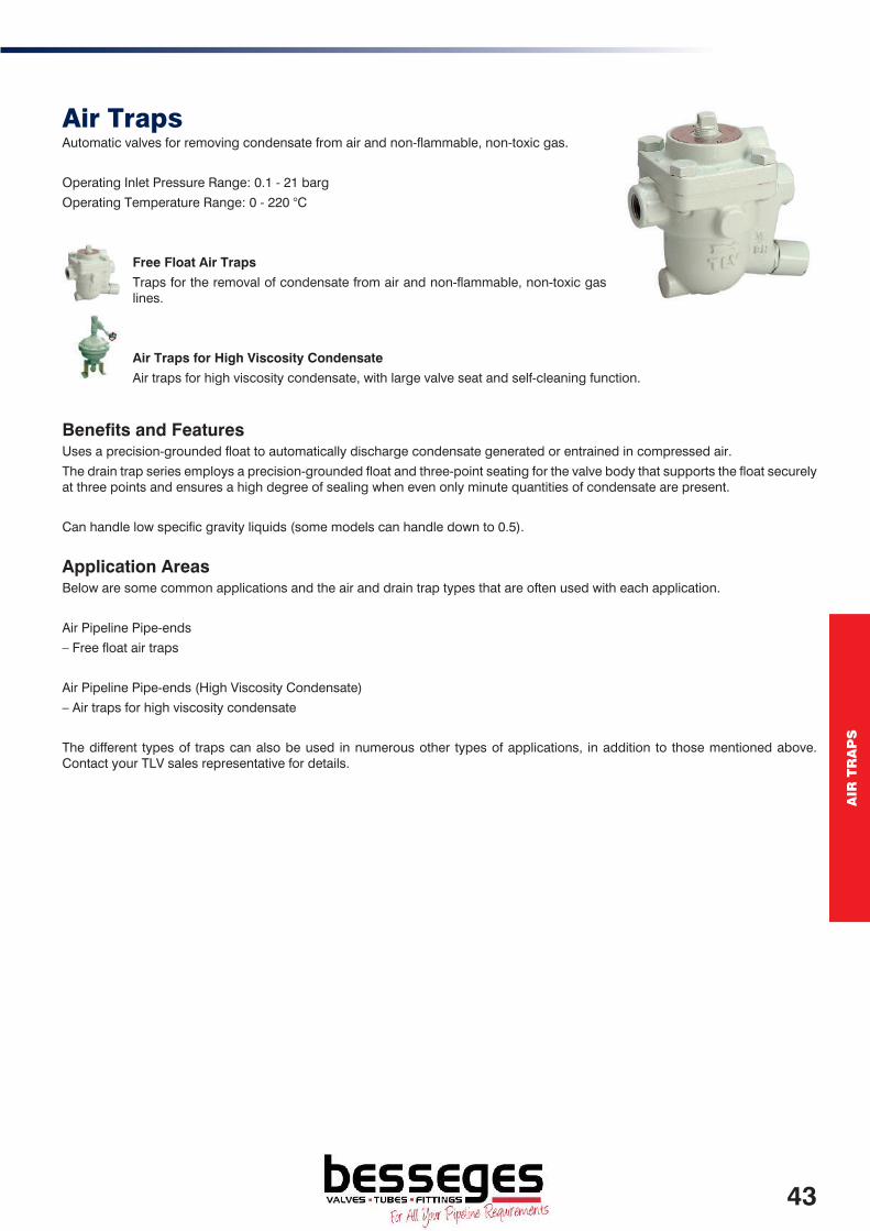
AIR
TR
AP
S
Air TrapsAutomatic valves for removing condensate from air and non-flammable, non-toxic gas.
Operating Inlet Pressure Range: 0.1 - 21 barg
Operating Temperature Range: 0 - 220 °C
Free Float Air Traps
Traps for the removal of condensate from air and non-flammable, non-toxic gas lines.
Air Traps for High Viscosity Condensate
Air traps for high viscosity condensate, with large valve seat and self-cleaning function.
Benefits and FeaturesUses a precision-grounded float to automatically discharge condensate generated or entrained in compressed air.
The drain trap series employs a precision-grounded float and three-point seating for the valve body that supports the float securely at three points and ensures a high degree of sealing when even only minute quantities of condensate are present.
Can handle low specific gravity liquids (some models can handle down to 0.5).
Application AreasBelow are some common applications and the air and drain trap types that are often used with each application.
Air Pipeline Pipe-ends
– Free float air traps
Air Pipeline Pipe-ends (High Viscosity Condensate)
– Air traps for high viscosity condensate
The different types of traps can also be used in numerous other types of applications, in addition to those mentioned above. Contact your TLV sales representative for details.
43

Free Float Air TrapsA
IR T
RA
PS
Air TrapsFree Float Air TrapsTraps for the removal of condensate from air lines and non-hazardous gases.
Operating Inlet Pressure Range: 0.1 - 16 barg
Operating Temperature Range: 0 - 100 °C
Benefits and FeaturesFree float construction using a precision-grounded float
The valve opening is under a continuous water-seal, so no air can escape through the valve.
Long Service LifeThe high precision spherical float rotates, allowing its entire surface to function as valve sealing surfaces and thus ensuring long service life.
Stable Operation of Air-using FacilitiesThe scale-removal function can be used to eliminate oily clogs without disassembling the body (JA3).
Easy PipeworkCompact, light-weight design requires little installation space.
JA3DCompact free float air trap with built-in strainer to automatically drain condensate from air lines.
JA3Light free float air trap with built-in strainer to discharge condensate or oil from air systems. Manual blowdown feature assists with removal of oily clogs.
SS1VGFree float drain trap with built-in strainer, can be used up to 21 barg. For use with both air and non-flammable, non-toxic gas.
For use on vertical pipelines. Available with rubber seat “-R” for a “bubble-tight” seal (up to 10 barg, 150 °C) or metal seat “-M” (up to 21 barg). Four orifice sizes – from max pressure of 5 barg (greatest capacity) to max pressure of 21barg.
ModelMax Operating Pressure (barg)
Max Operating Temperature (°C)
Max Allowable Pressure (barg)
Max Allowable Temperature (°C)
Body Material
JA3D 16 100 16 100 Zinc Alloy
JA3 16 100 21 100 Ductile Cast Iron
SS1VG-R 10 150 21 220 Stainless Steel
SS1VG-M 5, 10, 16, 21 220 21 220 Stainless Steel
Model Body MaterialConnection
Type1/2"
DN153/4"
DN201"
DN25
JA3D Zinc Alloy* Screwed 190.00 - -
JA3 S.G.Iron Screwed 184.00 196.00 211.00
SS1VG-R Stainless Steel Screwed 597.50 614.00 629.00
SS1VG-M Stainless Steel Screwed 597.50 614.00 629.00
* All internal parts are made from Stainless Steel.
44
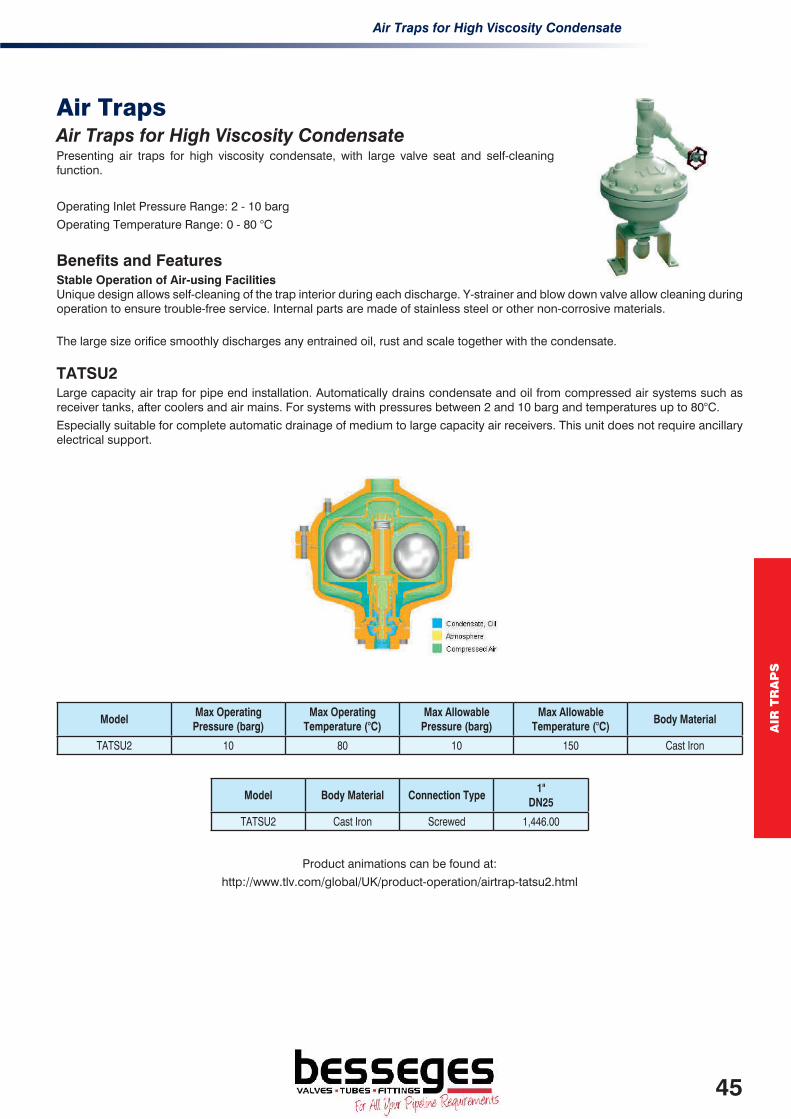
Air Traps for High Viscosity Condensate
AIR
TR
AP
S
Air TrapsAir Traps for High Viscosity CondensatePresenting air traps for high viscosity condensate, with large valve seat and self-cleaning function.
Operating Inlet Pressure Range: 2 - 10 barg
Operating Temperature Range: 0 - 80 °C
Benefits and FeaturesStable Operation of Air-using FacilitiesUnique design allows self-cleaning of the trap interior during each discharge. Y-strainer and blow down valve allow cleaning during operation to ensure trouble-free service. Internal parts are made of stainless steel or other non-corrosive materials.
The large size orifice smoothly discharges any entrained oil, rust and scale together with the condensate.
TATSU2Large capacity air trap for pipe end installation. Automatically drains condensate and oil from compressed air systems such as receiver tanks, after coolers and air mains. For systems with pressures between 2 and 10 barg and temperatures up to 80°C.
Especially suitable for complete automatic drainage of medium to large capacity air receivers. This unit does not require ancillary electrical support.
ModelMax Operating Pressure (barg)
Max Operating Temperature (°C)
Max Allowable Pressure (barg)
Max Allowable Temperature (°C)
Body Material
TATSU2 10 80 10 150 Cast Iron
Model Body Material Connection Type1"
DN25
TATSU2 Cast Iron Screwed 1,446.00
Product animations can be found at:
http://www.tlv.com/global/UK/product-operation/airtrap-tatsu2.html
45

ST
EA
M T
RA
PS
Steam TrapsSummary
A steam trap is an automatic valve that discharges condensate generated during processes and in steam transport lines, without allowing the discharge of any steam.
Steam trap operation principles can be roughly divided into three categories – mechanical, thermostatic and thermodynamic. TLV manufactures all three of these categories.
An extensive product line-up makes it possible to select the optimal product to suit the objective or application.
Each trap offers the highest level of energy conservation in its class.
Significant consideration is given to the aspect of maintenance; as evidenced by the designs of the steam traps. These include interchangeable parts and utilisation of re-useable PTFE gaskets.
TLV has developed the ‘Free Float Trap’ to eliminate the problems previously experienced by mechanical steam traps. Due to its success, it has become one of TLV’s core products, leading the industry with regards to innovation and reliability.
The development of the Free Float Steam Trap has increased the longevity and reliability of the trap by reducing the number of moving parts to one – the “Free Float”. The high quality component has a spherical tolerance of only 0.004D, resulting in unparalleled sealing performance, even when operating under low condensate loads at high pressures and temperatures.
All Free Float Steam Traps are designed with an integral perforated stainless steel strainer screen, again extending the life of the trap internals.
Rapid start up of processes is assisted by balanced pressure X-element or bi-metal air-vents located at the top of the traps where incondensable gases tend to accumulate.
The operation principle of mechanical traps takes advantage of the difference between the density of condensate and steam.
Free Float Steam Traps offer the following features:
• The moving float provides an infinite number of contact surfaces with the valve seat, ensuring long service life.
• Air venting feature for improved equipment productivity.
• Compact design with no levers or hinges.
• Large tolerance for backpressure allows for problem-free operation.
Suitable for use in a variety of applications, including steam main lines, heat exchangers and insulation of tracing lines.
47

S
TE
AM
TR
AP
S
Application GuideBelow are some common applications and the steam trap types that are often used for each application.
INDUSTRIAL APPLICATIONS TRAP CHOICESuperheated Steam – All Service P ≤ 80 barg 80 barg < P ≤ 120 barg 120 barg < P ≤ 260 barg
FFT FF TD
Saturated Steam Mains FFTSteam TurbinesSupply Lines Governor/Trip & Throttle Valve Casing Drains: P ≤ 0 barg Casing Drains: P > 0 barg Exhaust Steam Lines: P ≤ 0 barg Exhaust Steam Lines: P > 0 barg
FFT FFT MPT FFT MPT FFT
Process Equipment Supply Lines FFTTracing LinesLow Temperature: T ≤ 80°C High Temp. Supported: T > 80°C High Temp. Unsupported: T > 80°C Sampling Equipment: T ≤ 70°C Sampling Equipment: T > 70°C
BMT FFT BPT BMT FFT
Sulphur UnitPit Coils Jacketed Pipe
FF-LRV FFT
Process Heaters: P ≤ 10 barg SupplyStall Condition No Stall Condition
MPT FFT
Process Heaters: P > 10 barg SupplyStall Condition No Stall Condition
FFT / MP FFT
Storage Tank Heating with Temperature Control Valve Stall Condition No Stall Condition
MPT FFT
Storage Tank Heating without Temperature Control ValveTemperature Control Not Required Partial Temperature Control by Trap
FFT BMT
INDUSTRIAL APPLICATIONS TRAP CHOICEFreeze Protection BMTMotive Steam Supply to Mechanical Pump FFTExtrudersBarrel Jackets / Screen Holder Die Plate
FFT FFT
Paper MillsDigesters Rolling Dryers Press Dryer
FFT FF-LRV
FFTSurface Condensers (Require a Pressure-Balancing Line)Intercooler After Cooler Gland Seal Condenser
FF FF FF
Vacuum Jets Supply Line FFTHeating and Air ConditioningAbsorption Chillers Air heating Coils with Stall Condition Air heating Coils without Stall Condition Heat Exchangers with Stall Condition Heat Exchangers without Stall Condition Radiators
FFT MPT FFT MPT FFT BPT
Hospital EquipmentSterilisers / Autoclaves FFTFood EquipmentKettles Boiling Pans - Fixed / Tilting Hot Plates / Ovens Retorts
FFT FFT FFT FFT
Process EquipmentBrewing Coppers Drying Coils / Water Heaters Platen Presses Vulcanisers
FFT FFT FFT FFT
FFT - Free Float with Thermostatic Air VentFF - Free FloatFF-LRV - Free float with Lock Release ValveTD - Thermodynamic
MPT - Mechanical Pump with Built-in TrapMP - Mechanical PumpBPT - Balanced Pressure ThermostaticBMT - Bimetal Thermostatic (Temp. Control Trap)
48

ST
EA
M T
RA
PS
Free Float Steam Traps Summary
The operation principle for these steam traps utilises buoyancy.
Operating Inlet Pressure Range: 0.1 - 120 barg
Operating Temperature Range: 0 - 530 °C (up to 600 °C on special applications)
Free Float Steam Traps (Low Pressure) Free float steam traps, which offer continuous discharge, are optimal for processes.
Models for use on low pressure up to 21 barg.
Free Float Steam Traps (Medium / High Pressure) Free float steam traps, which offer continuous discharge, are optimal for processes.
Models for use on mid to high pressure up to 120 barg, and some models for main lines are also available.
Free Float Steam Traps for Main Lines Free float steam traps for main lines, with a tight seal even under low condensate load conditions.
Large Capacity Float Steam Traps Large capacity steam traps with a maximum discharge capacity of 150,000 kg/h.
For Clean Steam Free Float Traps – see Clean Steam Trap Section.
Orifice Sizing
The orifice size for the free float steam trap is based on the maximum steam pressure and the maximum differential pressure. The orifice should be selected based on the above in mind and with reference to the capacity charts available on the Steam Trap Datasheets (SDS sheet). The SDS are available online at www.TLV.com or can be obtained by contacting your local Regional Sales Engineer or TLV Sales Office.
Product animations can be found at:
http://www.tlv.com/global/UK/product-operation/free-float-steam-trap-jx.html
49

J-SeriesS
TE
AM
TR
AP
S
Free Float Steam Traps (Low Pressure)J-SeriesSteam Traps for low pressure processes.
Benefits and FeaturesImproved Efficiency of Heating Equipment and Reduced Maintenance CostsThe float (free float) rises and falls as the flow of condensate fluctuates, opening the valve to discharge condensate and closing off the valve when steam enters.
The built-in X-element functions as an air vent, discharging both cool and hot air. As a result, the steam chamber inside the equipment contains only steam, which allows the equipment to achieve optimised heating performance.
Long Service Life, Excellent DurabilityThe high precision spherical float rotates, allowing its entire surface to function as valve sealing surfaces and thus ensuring a long service life. The bodies of the J3S-X and J5S-X and J6SX models are constructed of stainless steel for increased durability.Built-in strainers.
Protects EquipmentThe X-element is designed to fail open, so the valve remains open even in the event of failure.
J3X / JF3X / J5X / JF5X Free float steam trap with built-in strainer and X-element type automatic air vent, for use on process equipment.
Lock release valve option available.
J3SX / JF3SX / J5SX / J6SXAll stainless steel construction free float steam trap with integral strainer for use on process equipment.
J7X / J7.2X / J7.5X / J8XFree float steam trap with built-in strainer and X-element type automatic air vent, for use on process equipment.
ModelMax Differential
Pressure range (barg)Max Operating
Temperature (°C)Max Allowable
Pressure (barg)Max Allowable
Temperature (°C)Body Material
Capacities up to kg/h
J3X 2, 5, 8, 10, 13 200 13 200 Ductile Cast Iron 700J3SX 2, 5, 10, 14, 21 220 21 220 Stainless Steel 760J5X 2, 5, 8, 10, 13 200 13 200 Ductile Cast Iron 1,000
J5SX 2, 5, 10, 14, 21 220 21 220 Stainless Steel 1,050J6SX 2, 5, 10, 16, 21 220 21 220 Stainless Steel 3,500J7X 2.5, 5, 10, 13 200 13 200 Cast Iron 3,000
J7.2X 0.5, 1, 2, 5, 10, 13 200 13 200 Cast Iron 7,000J7.5X 1, 2, 5, 10, 13 200 13 200 Cast Iron 15,000J8X 0.5, 1, 2, 5, 10, 13 200 13 200 Cast Iron 20,000
Model Body MaterialConnection
Type1/2"
DN153/4"
DN201"
DN251 1/4" DN32
1 1/2" DN40
2" DN50
3" DN80
4" DN100
J3X^ Ductile Cast Iron Screwed 189.00 199.50 259.50 - - - - -JF3X^ Ductile Cast Iron Flanged 316.00 332.00 444.00 - - - - -J3SX^ Stainless Steel Screwed 225.00 235.00 247.00 - - - - -JF3SX Stainless Steel Flanged 380.00 396.00 421.00 - - - - -J5X^ Ductile Cast Iron Screwed - 341.50 341.50 388.50 388.50 - - -
JF5X^ Ductile Cast Iron Flanged - 438.00 462.00 486.00 559.00 638.50 - -J5SX^ Stainless Steel Screwed - 493.50 496.00 515.50 545.00 - - -J5SX^ Stainless Steel Flanged - 870.50 875.00 - - - - -J6SX^ Stainless Steel Screwed 534.50 544.00 550.00 - - - - -JS7X^ Cast Iron Screwed - - 716.00 - 757.00 - - -J7X^ Cast Iron Flanged - 798.00 798.00 805.50 805.50 821.00 - -
J7.2X^ Cast Iron Flanged - - - - 1,385.00 1,424.00 - -J7.5X^ Cast Iron Flanged - - - - 1,734.50 1,773.50 1,910.00 -J8X^ Cast Iron Flanged - - - - - 3,774.00 3,968.00 4,117.00
^ Other connection standards available.
Lock release valve option available, typically used on heated rollers and plating tank coils.
50
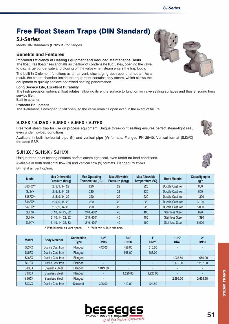
SJ-Series
ST
EA
M T
RA
PS
Free Float Steam Traps (DIN Standard)SJ-SeriesMeets DIN standards (DN2501) for flanges.
Benefits and FeaturesImproved Efficiency of Heating Equipment and Reduced Maintenance CostsThe float (free float) rises and falls as the flow of condensate fluctuates, opening the valve to discharge condensate and closing off the valve when steam enters the trap body.
The built-in X-element functions as an air vent, discharging both cool and hot air. As a result, the steam chamber inside the equipment contains only steam, which allows the equipment to quickly achieve optimised heating performance.
Long Service Life, Excellent DurabilityThe high precision spherical float rotates, allowing its entire surface to function as valve sealing surfaces and thus ensuring long service life.Built-in strainer.
Protects EquipmentThe X-element is designed to fail open, so the valve remains open even in the event of failure.
SJ3FX / SJ3VX / SJ5FX / SJ6FX / SJ7FX Free float steam trap for use on process equipment. Unique three-point seating ensures perfect steam-tight seal, even under no-load conditions.
Available in both horizontal pipe (N) and vertical pipe (V) formats. Flanged PN 25/40. Vertical format (SJ3VX) threaded BSP.
SJH3X / SJH5X / SJH7X Unique three-point seating ensures perfect steam-tight seal, even under no-load conditions.
Available in both horizontal flow (N) and vertical flow (V) formats. Flanged PN 25/40.
Bi-metal air vent option.
ModelMax Differential Pressure (barg)
Max Operating Temperature (°C)
Max Allowable Pressure (barg)
Max Allowable Temperature (°C)
Body MaterialCapacity up to
kg/h
SJ3FX** 2, 5, 9, 14, 22 220 22 220 Ductile Cast Iron 800SJ3VX 2, 5, 9, 14, 22 220 22 220 Ductile Cast Iron 800
SJ5FX** 2, 5, 9, 14, 22 220 22 220 Ductile Cast Iron 1,390SJ6FX** 2, 5, 9, 14, 22 220 22 220 Ductile Cast Iron 3,100SJ7FX** 2, 5, 9, 14, 22 220 22 220 Ductile Cast Iron 5,000SJH3X 5, 10, 14, 22, 32 240, 400* 40 400 Stainless Steel 890SJH5X 5, 10, 14, 22, 32 240, 400* 40 400 Stainless Steel 1,390SJH7X 5, 10, 14, 22, 32 240, 400* 40 400 Stainless Steel 5,000
* With bi-metal air vent option. ** With two built-in strainers.
Model Body MaterialConnection
Type1/2"
DN153/4"
DN201"
DN251 1/2" DN40
2" DN50
SJ3FX Ductile Cast Iron Flanged 442.00 456.00 510.50 - -SJ5FX Ductile Cast Iron Flanged - 568.00 588.00 - -SJ6FX Ductile Cast Iron Flanged - - - 1,037.50 1,069.00SJ7FX Ductile Cast Iron Flanged - - - 1,172.00 1,237.00SJH3X Stainless Steel Flanged 1,049.00 - - - -SJH5X Stainless Steel Flanged - 1,220.00 1,220.00 - -SJH7X Stainless Steel Flanged - - - 2,599.00 2,635.50SJ3VX Ductile Cast Iron Screwed 398.00 412.00 424.50 - -
51

JH-SeriesS
TE
AM
TR
AP
S
Free Float Steam Traps (Medium / High Pressure)JH-SeriesSuitable for medium to high pressure processes.
Operating Inlet Pressure Range: 0.1 - 120 barg
Operating Temperature Range: 0 - 530 °C
Benefits and FeaturesImproved Efficiency of Heating Equipment and Reduced Maintenance CostsThe float (free float) rises and falls as the flow of condensate fluctuates, opening the valve to discharge condensate and closing off the valve when steam enters.
The built-in X-element functions as an air vent, discharging both cool and hot air. As a result, the steam chamber inside the equipment contains only steam, which allows the equipment to achieve optimised heating performance.
Long Service Life, Excellent DurabilityThe high precision spherical float rotates, allowing its entire surface to function as valve sealing surfaces and thus ensuring long service life. Built-in strainer.
Protects EquipmentThe X-element is designed to fail open, so the valve remains open even in the event of failure.
JH3SX / JH3SBAll stainless steel construction free float trap for use on high pressure process applications.
Optional bi-metal air vent (JH3SB) for max allowable temperature of 350°C.
JH5RLX / JH5RLB / JH5SLX / JH5SLBCast steel (JH5RLX) / All Stainless Steel (JH5SLX) construction free float trap for use on high pressure process applications.
Optional bi-metal air vent (JH5RLB / JH5SLB) for max operating pressure is 46 barg.
JH5RHB / JH5SHBCast steel (JH5RHB) / all stainless steel (JH5SHB) construction free float trap for use on high pressure process applications.
ModelMax Differential Pressure (barg)
Max Operating Temperature (°C)
Max Allowable Pressure (barg)
Max Allowable Temperature (°C)
Body MaterialCapacity up to
kg/hJH3 SX 2, 5, 10, 14, 22, 32 240 32 350 Stainless Steel 600JH3 SB 2, 5, 10, 14, 22, 32 350 32 350 Stainless Steel 600
JH5 RL X 5, 10, 14, 22, 32 240 40 400 Cast Steel 1,000JH5 RL B 2, 5, 10, 14, 22, 32, 40, 46 400 46 400 Cast Steel 1,000JH5 RH B 80 400 80 400 Cast Steel 1,200JH5 SL X 5, 10, 22, 32 240 40 425 Stainless Steel 1,000JH5 SL B 2, 5, 10, 14, 22, 32,40, 46 425 46 425 Stainless Steel 1,000JH5 SH B 65 425 65 425 Stainless Steel 150
Model Body MaterialConnection
Type1/2"
DN153/4"
DN201"
DN251 1/2" DN40
2" DN50
JH3 SX/B^Stainless Steel Screwed/SW 375.00 402.00 428.50 - -Stainless Steel Flanged** 583.00 625.00 645.00 - -
JH5 RL X/B^Cast Steel Screwed/SW 742.50 750.00 772.00 - -Cast Steel Flanged** 862.00 888.50 911.50 1,058.50 1,079.50
JH5 RH B^Cast Steel SW 1,407.00 1,434.50 1,461.50 1,498.50 1,539.50Cast Steel Flanged** 1,557.00 1,623.50 1,670.50 1,957.50 2,286.00
JH5 SL X/B^Stainless Steel Screwed/SW 1,108.00 1,133.00 1,155.00 1,204.50 1,317.00Stainless Steel Flanged** 1,283.00 1,315.00 1,396.50 1,656.00 1,668.50
JH5 SH B^Stainless Steel SW 1,474.50 1,518.50 1,564.50 1,621.50 1,670.50Stainless Steel Flanged** 1,621.50 1,674.00 1,730.50 2,013.00 2,061.00
* SW only ^ other connection standards available.** Connections according to DIN/ASME available.
52

JH-Series (Cont 1)
ST
EA
M T
RA
PS
Free Float Steam Traps (Medium / High Pressure)JH-Series (Cont 1)Suitable for medium to high pressure processes.
Operating Inlet Pressure Range: 0.1 - 120 barg
Operating Temperature Range: 0 - 530 °C
Benefits and FeaturesImproved Efficiency of Heating Equipment and Reduced Maintenance Costs.The float (free float) rises and sinks as the flow of condensate fluctuates, opening the valve to discharge condensate and closing off the valve when steam enters.
The built-in X-element functions as an air vent, discharging both cool and hot air. As a result, the steam chamber inside the equipment contains only steam, which allows the equipment to achieve optimised heating performance.
Long Service Life, Excellent DurabilityThe high precision spherical float rotates, allowing its entire surface to function as valve sealing surfaces and thus ensuring long service life.
Protects EquipmentThe X-element is designed to fail open, so the valve remains open even in the event of failure.
JH7RLX / JH7RLBFree float trap for use on high pressure process applications.
Optional bimetal automatic air vent for maximum operating pressure is 46 barg.
JH7RMBFree float trap for use on high pressure process applications.
JH7RHB / JH7RHP / JH7RHWFree float trap for use on high pressure process applications.
ModelMax Differential Pressure (barg)
Max Operating Temperature (°C)
Max Allowable Pressure (barg)
Max Allowable Temperature (°C)
Body MaterialCapacity up to
kg/h
JH7 RL X 2, 5, 10, 14, 22, 32 240 40 400 Cast Steel 5,000
JH7 RL B 2, 5, 10, 14, 22, 32, 40, 46 400 46 400 Cast Steel 5,000
JH7 RM B 65 400 65 400 Cast Steel 4,000
JH7 RH B/(P/W) 80 ,100, (120) 425 (530) 120 425 (530) Cast Steel 6,000
Values in () are those for P/W variations only
Model Body MaterialConnection
Type1/2"
DN153/4"
DN201"
DN251 1/2" DN40
2" DN50
JH7 RL X/B^Cast Steel Screwed/SW - 1,416.50 1,448.00 1,536.00 1,580.50
Cast Steel Flanged** - 1,537.00 1,579.00 1,592.00 1,721.00
JH7 RM B^Cast Steel SW - 2,117.00 2,192.50 2,352.00 2,421.50
Cast Steel Flanged** - 2,270.00 2,324.00 2,513.00 2,752.00
JH7 RH B/P/W^Cast Steel SW 5,173.50 5,173.50 5,173.50 - -
Cast Steel Flanged** 5,968.00 5,968.00 5,968.00 - -* SW only ^ other connection standards available. ** Connections according to DIN/ASME available.
53

JH-Series (Cont 2)S
TE
AM
TR
AP
S
Free Float Steam Traps (Medium / High Pressure)JH-Series (Cont 2)Suitable for medium to high pressure processes.
Operating Inlet Pressure Range: 0.1 - 120 barg
Operating Temperature Range: 0 - 530 °C (up to 600 °C on special applications)
Benefits and FeaturesImproved Efficiency of Heating Equipment Reduced Maintenance CostsThe float (free float) rises and falls as the flow of condensate fluctuates, opening the valve to discharge condensate and closing off the valve when steam enters.
The built-in X-element functions as an air vent, discharging both cool and hot air. As a result, the steam chamber inside the equipment contains only steam, which allows the equipment to achieve optimised heating performance.
Long Service Life, Excellent DurabilityThe high precision spherical float rotates, allowing its entire surface to function as valve sealing surfaces ensuring long service life.
Protects EquipmentThe X-element is designed to fail open, so the valve remains open even in the event of failure.
JH7.2RX/B / JH7.5RX/B / JH8RX/BFree float trap for use on high pressure process applications. Optional bi-metal air vent for max operating pressure up to 46 barg.
JH15E / JH15M / JH15S Extra-large capacity high pressure float steam trap with two built-in screens. Maximum operating pressure is 46 barg. FLOATDYNAMIC® feature uses a free float as a pilot valve.
ModelMax Differential Pressure (barg)
Max Operating Temperature (°C)
Max Allowable Pressure (barg)
Max Allowable Temperature (°C)
Body MaterialCapacity up to
kg/hJH7.2RX 2, 5, 10, 14, 22, 32 240 46 400 Cast Steel 6,000JH7.2RB 2, 5, 10, 14, 22, 32, 40, 46 400 46 400 Cast Steel 6,000JH7.5RX 2, 5, 10, 14, 22, 32 240 46 400 Cast Steel 15,000JH7.5RB 2, 5, 10, 14, 22, 32, 40, 46 400 46 400 Cast Steel 15,000JH8RX 0.5, 2, 5, 10, 14, 22, 32 240 46 400 Cast Steel 25,000JH8RB 0.5, 2, 5, 10, 14, 22, 32,40, 46 400 46 400 Cast Steel 25,000
JH15E-21 21 400 50 400 Cast Steel 130,000JH15M-21 21 400 50 400 Cast Steel 68,000JH15S-21 21 400 50 400 Cast Steel 25,000JH15E-46 46 400 50 400 Cast Steel 160,000JH15M-46 46 400 50 400 Cast Steel 85,000JH15S-46 46 400 50 400 Cast Steel 25,000
Model Body MaterialConnection
Type1 1/2" DN40
2" DN50
3" DN80
4" DN100
JH7.2R X/B^Cast Steel SW 2,323.00 2,445.50 - -Cast Steel Flanged** 2,323.00 2,445.50 - -
JH7.5R X/B^Cast Steel SW 3,339.00 3,359.00 3,702.50 -Cast Steel Flanged** 3,339.00 3,359.00 3,702.50 -
JH8R X/B^Cast Steel SW - 6,254.00 6,558.50 6,797.00Cast Steel Flanged** - 6,254.00 6,558.50 6,797.00
JH15E/M/S-21^ Cast Steel Flanged** - - - 12,608.50JH15E/M/S-46^ Cast Steel Flanged** - - - 14,404.00
^ Other connection standards available. ** Connections according to DIN/ASME available.
54

S-Series
ST
EA
M T
RA
PS
Free Float Steam Traps (For Mains Lines)S-SeriesSuitable for mains lines drainage.
Operating Inlet Pressure Range: 0.1 - 46 barg
Operating Temperature Range: 0 - 425 °C
Benefits and FeaturesImproved Efficiency of Heating Equipment and Reduced Maintenance CostsThe float (free float) rises and falls as the flow of condensate fluctuates, opening the valve to discharge condensate and closing off the valve when steam enters.
Automatic bi-metal air vent for rapid start up. As a result, the steam space contains only steam, which allows optimised heating performance.
Long Service Life, Excellent DurabilityThe high precision spherical float rotates, allowing its entire surface to function as a valve sealing surface ensuring long service life. Furthermore the internal built-in strainer ensures the steam traps excellent durability.
SS1 Maintainable free float trap for use on steam mains. Available in horizontal (N) and vertical (V) formats and low (L) and high (H) temperature option.
SS3Sealed free float trap for use on steam mains. Welded all stainless steel construction with built-in strainer. Available in horizontal (N) and vertical (V) formats. Insulation cover also available.
SS3 BioSealed free float trap designed for biotechnical applications. Complete condensate discharge after shutdown by being of a free draining design. Welded stainless steel construction with built-in strainer. Vertical format only.
SS5Free float trap for use on steam mains. Unique three-point seating ensures steam-tight seal, even under no-load conditions. Welded all stainless steel construction with built-in strainer. Available in horizontal (N) and vertical (V) formats.
For Free Float Quick Traps – see our QuickTrap Section
ModelMax Differential Pressure (barg)
Max Operating Tem-perature (°C)
Max Allowable Pres-sure (barg)
Max Allowable Tem-perature (°C)
Body MaterialCapacity up to
kg/hSS1(L) 5, 10, 21 220 21 220 Stainless Steel 200SS1(H) 5, 10, 21 350 21 350 Stainless Steel 200
SS3 5, 10, 21 400 24 400 Stainless Steel 300SS3 Bio 5, 10, 21 260 21 260 Stainless Steel 300SS5 (H) 5, 10, 16, 21, 32, (46) 425 46 425 Stainless Steel 800
Model Body MaterialConnection
Type1/2"
DN153/4"
DN201"
DN25
SS1^Stainless Steel Screwed/SW 252.00 272.00 278.50
Stainless Steel Flanged** 339.00 351.00 377.00
SS3^Stainless Steel Screwed/SW 250.00 262.50 292.00
Stainless Steel Flanged** 376.00 387.50 401.00
SS3 Bio Stainless Steel Screwed 483.00 496.00 524.00
SS5(H)^Stainless Steel Screwed/SW 418.00 439.00 469.50
Stainless Steel Flanged** 672.00 769.50 844.00^ Other connection standards available. ** Connections according to DIN/ASME available.
55

SH-SeriesS
TE
AM
TR
AP
S
Free Float Steam Traps (High Pressure)SH-SeriesSuitable for very high pressures and superheated steam
Operating Inlet Pressure Range: 14 - 100 barg
Operating Temperature Range: 0 - 400 °C
Benefits and FeaturesImproved Efficiency of Heating Equipment and Reduced Maintenance CostsThe float (free float) rises and falls as the flow of condensate fluctuates, opening the valve to discharge condensate and closing off the valve when steam enters.
The built-in bi-metal an air vent, discharging both cool and hot air. As a result, the steam chamber inside the equipment contains only steam, which allows the equipment to achieve optimised heating performance.
Long Service Life, Excellent DurabilityThe high precision spherical float rotates, allowing its entire surface to function as a valve sealing surface ensuring long service life.Futhermore the internal built-in strainer ensures the steam traps excellent durability.
SH3NLFree float steam trap with built-in strainer for use on high pressure steam mains
For use on horizontal pipelines.
SH5NL / SH5NHFree float steam trap with built-in strainer for use on high pressure steam mains. For use on horizontal pipelines.
ModelMax Differential Pressure (barg)
Max Operating Temperature (°C)
Max Allowable Pressure (barg)
Max Allowable Temperature (°C)
Body Material Capacity up to kg/h
SH3NL 14, 32, 45 400 45 400 Cast Steel 300
SH5NL/H 14, 32, 46, 65, 100* 400 65, 100* 400 Cast Steel 600
*For SH5NH only.
Model Body MaterialConnection
Type1/2"
DN153/4"
DN201"
DN25
SH3NL^Cast Steel SW 849.50 863.00 879.00
Cast Steel Flanged** 860.00 870.50 901.00
SH5NL^Cast Steel SW 870.50 893.50 913.50
Cast Steel Flanged** 1,002.00 1,024.00 1,037.50
SH5NHCast Steel SW 1,446.00 1,460.50 1,486.00
Cast Steel Flanged** 1,656.00 1,918.50 2,067.50^ Other connection standards available. ** Connections according to ASME.
56

SH-Series (cont.)
ST
EA
M T
RA
PS
Free Float Steam Traps (High Pressure) SH-Series (cont.)Suitable for very high pressures and superheated steam
Operating Inlet Pressure Range: 14 - 100 barg
Operating Temperature Range: 0 - 400 °C
Benefits and FeaturesImproved Efficiency of Heating Equipment and Reduced Maintenance CostsThe float (free float) rises and falls as the flow of condensate fluctuates, opening the valve to discharge condensate and closing off the valve when steam enters.
The built-in X-element functions as an air vent, discharging both cool and hot air. As a result, the steam chamber inside the equipment contains only steam, which allows the equipment to achieve optimised heating performance.
Long Service Life, Excellent DurabilityThe high precision spherical float rotates, allowing its entire surface to function as valve sealing surfaces and thus ensuring long service life. Futhermore the internal built-in strainer ensures the steam traps excellent durability.
SH6NL / SH6NHFree float steam trap with built-in strainer for use on high pressure steam mains.
SH7NL / SH7NHFree float steam trap with built-in strainer for use on high pressure steam mains. For use on horizontal pipelines.
ModelMax Differential Pressure (barg)
Max Operating Temperature (°C)
Max Allowable Pressure (barg)
Max Allowable Temperature (°C)
Body Material Capacity up to kg/h
SH6NL/H 14, 32, 46, 65, 100* 400 65, 100* 400 Cast Steel 2,000
SH7NL/H 14, 32, 46, 65, 100* 400 65, 100* 400 Cast Steel 3,000
*For SH6NH and SH7NH respectively only.
Model Body MaterialConnection
Type3/4"
DN201"
DN251 1/2" DN40
2" DN50
SH6NL^Cast Steel SW - - 2,081.00 2,188.00
Cast Steel Flanged - - 2,851.00 2,908.50
SH6NHCast Steel SW - - 3,453.50 -
Cast Steel Flanged - 3,363.00 3,453.50 -
SH7NL^Cast Steel SW - - 2,810.00 2,841.50
Cast Steel Flanged - - 3,598.50 4,104.50
SH7NHCast Steel SW 3,922.00 3,922.00 3,922.00 4,100.00
Cast Steel Flanged 4,540.50 4,540.50 4,540.50 4,728.00^ Other connection standards available.Connections according to ASME.
57

Large Capacity TrapsS
TE
AM
TR
AP
S
Free Float Steam Traps (Large Capacity)Large Capacity TrapsSteam traps suitable for large levels of condensate.
Operating Inlet Pressure Range: 5 - 46 barg
Operating Temperature Range: 0 - 425 °C
Benefits and FeaturesImproved Efficiency of Heating Equipment and Reduced Maintenance CostsThe float (free float) rises and falls as the flow of condensate fluctuates, opening the valve to discharge condensate and closing off the valve when steam enters.
The built-in X-element functions as an air vent, discharging both cool and hot air. As a result, the steam chamber inside the equipment contains only steam, which allows the equipment to achieve optimised heating performance.
Long Service Life, Excellent DurabilityThe high precision spherical float rotates, allowing its entire surface to function as valve sealing surfaces and thus ensuring long service life.
Protects EquipmentThe X-element is designed to fail open, so the valve remains open even in the event of failure (fail open design).
J10 Extra-large capacity float steam trap. FLOATDYNAMIC® feature uses a free float as a pilot valve.
JL9X / JLH9X Lever Float with Dual Valve mechanism for high capacity, for use on process equipment. Features thermostatic air venting.
JL14X / JLH14X / JLH14BLever Float with Dual Valve mechanism for high capacity, for use on process equipment. Features thermostatic air venting.
Bi-metal air vent option.
ModelMax Differential Pressure (barg)
Max Operating Temperature (°C)
Max Allowable Pressure (barg)
Max Allowable Temperature (°C)
Body Material Capacity up to kg/h
J10 16 220 16 220 Cast Iron* 60,000JL 9X 10, 13 200 13 200 Cast Iron 18,000**
JL H 9X 10, 18, (32) 220 (240) 32 400 Cast Steel 18,000**JL 14X 10, 13 200 13 200 Cast Iron 60,000**
JL H 14X/B 10, 18 240 / 400ª 32 400 Cast Steel 60,000*** Cast Steel option available () Values are that for the 32 barg variant. ª With bi-metal air vent option ** Minimum flow rate is applicable
Model Body MaterialConnection
Type2"
DN503"
DN804"
DN100
J10^ Cast Iron Flanged - - 6,503.00
JL 9XCast Iron Screwed 1,568.00 - -Cast Iron Flanged 1,743.00 - -
JL H 9XCast Steel Screwed/SW 3,744.50 - -Cast Steel Flanged 3,744.50 - -
JL 14XCast Iron Screwed - 2,920.00 -Cast Iron Flanged - 2,920.00 -
JL H 14X/BCast Steel Screwed/SW - 4,792.00 -Cast Steel Flanged - 6,274.00 -
^ Other connection standards available.
58

Large Capacity Traps
ST
EA
M T
RA
PS
Thermodynamic Steam TrapsSummary
The operation principle for these traps utilises the difference in the thermodynamic properties of condensate and steam.
Also known as 'Disc Traps'
Operating Inlet Pressure Range: 0.3 - 260 barg
Operating Temperature Range: 0 - 550 °C
Disc Type Steam Traps
Extremely versatile disc type steam traps.
Benefits and FeaturesReduced Maintenance Costs
Disc type traps and impulse type traps are both examples of steam traps belonging to this classification. TLV’s thermodynamic steam traps are all disc type traps, which allow less steam leakage and have fewer problems with sticky scale and build-up of dirt.
Application Areas Suitable for a variety of applications, such a steam main lines, tracers, steam heating equipment, etc.
Product animations can be found at:
http://www.tlv.com/global/UK/product-operation/thermodynamic-steam-trap-a3n.html
59

Disc Type Steam Traps S
TE
AM
TR
AP
S
Thermodynamic Steam TrapsDisc Type Steam Traps
Operating Inlet Pressure Range: 0.3 - 46 barg Operating Temperature Range: 0 - 550 °C
Benefits and FeaturesReduced Maintenance CostsOnly TLV has a line of thermodynamic (disc) steam traps that have been developed to cover the complete range of pressures from Low Pressures to Super-high Pressures (260 barg).
Insulating Air JacketDisc steam trap operation may suffer if the trap is exposed to cold air and rain, so to prevent wasteful leakage of steam TLV has developed a steam-jacketed pressure chamber model. The high-precision machined disc valve and valve seat offer excellent sealing properties, preventing wasteful discharge of steam. Other models include an integrated air jacket.
Integrated Bimetal Air VentProductivity is impaired if the large amounts of cold condensate and air inside the system are not discharged as soon as the equipment is started up. With the exception of models P46S, HR150A and HR260A, all models have an integral bimetal type automatic air venting feature. The valve is fully open when temperatures are low, allowing for the rapid discharge of cold condensate and air.
A3NSteam-jacketed pressure chamber model. Operates well even when subjected to harsh environmental conditions.
P46S Thermodynamic steam trap which can be used up to 21 barg.
P46SRN Thermodynamic steam trap which can be used up to 46 barg.
P46SRM Thermodynamic steam trap which can be used up to 46 barg.
P46SRWThermodynamic steam trap which can be used to up to 46 barg. It features a single internal wider passage which is less likely to block.
P65SRN Thermodynamic steam trap which can be used up to 65 barg.
ModelMax Differential Pressure (barg)
Max Operating Temperature (°C)
Max Allowable Pressure (barg)
Max Allowable Temperature (°C)
Body Material Capacity up to kg/h
A3N 13 200 13 200 Cast Iron 650P46S 21 400 42 400 Stainless Steel 420
P46SRN 46 425* 56 425/550* Carbon Steel/SS 750P46SRM 46 425* 56 425/550* Forged Steel/SS 1,400P46SRW 46 425* 46 425* Carbon Steel 2,500P65SRN 65 425* 65 425/550* Carbon Steel/SS 450
*400°C on PN Flange models
Model Body MaterialConnection
Type1/4" DN8
3/8" DN10
1/2" DN15
3/4" DN20
1" DN25
A3N^Cast Iron Screwed - - 127.00 163.00 221.50Cast Iron Flanged - - 223.00 275.00 298.00
P46S^ Stainless Steel Screwed 106.00 106.00 106.00 - -
P46SRN^
Carbon Steel Screwed/SW - - 127.00 130.00 134.50Carbon Steel Flanged - - 201.50 208.00 241.50
Stainless Steel Screwed/SW - - 167.00 171.00 176.50Stainless Steel Flanged - - 227.00 245.00 289.00
P46SRM^Carbon Steel Screwed/SW - - 198.50 204.00 221.50Carbon Steel Flanged - - 387.50 412.50 444.00
P46SRW* Carbon Steel Screwed/SW - - - - 286.50
P65SRN^Carbon Steel SW - - 216.50 233.00 305.50Carbon Steel Flanged - - 466.00 476.00 502.00
^ Other connection standards and stainless steel options available. * Flanged connection also available.
60

Disc Type Steam Traps (Cont)
ST
EA
M T
RA
PS
Thermodynamic Steam TrapsDisc Type Steam Traps (Cont)
Operating Inlet Pressure Range: 8 - 260 barg
Operating Temperature Range: 0 - 550 °C
Benefits and FeaturesReduced Maintenance CostsOnly TLV has a line of thermodynamic (disc) steam traps that have been developed to cover the complete range of pressures from Low Pressures to Super-high Pressures (260 barg).
In-line maintenanceWith the exception of models P46S and P46UC, the valve and valve seat of all models are a single, modular unit, allowing for easy and economical maintenance when replacement is necessary due to wear, etc. The entire trap on model P46UC is inline replaceable.
Air-jacketed pressure chamberDisc steam trap operation may suffer if the trap is exposed to cold air and rain, so to prevent wasteful leakage of steam TLV has developed an air-jacketed pressure chamber model. The high-precision machined disc valve and valve seat offer excellent sealing properties, preventing wasteful discharge of steam.
HR80A Thermodynamic steam trap which can be used on pressures up to 80 barg.
HR150A Thermodynamic steam trap which can be used on high pressures up to 150 barg.
HR260A Thermodynamic steam trap which can be used on high pressures up to 260 barg.
ModelMax Differential Pressure (barg)
Max Operating Temperature (°C)
Max Allowable Pressure (barg)
Max Allowable Temperature (°C)
Body Material Capacity up to kg/h
HR80A 80 475 80 475 Alloy Steel 190
HR150A 150 550 150 550 Alloy Steel 230
HR260A 260 550 260 550 Alloy Steel 230
Model Body MaterialConnection
Type1/2"
DN153/4"
DN201"
DN25
HR80AAlloy Steel SW / BW 834.00 883.00 915.50
Alloy Steel Flanged 1,477.50 1,567.00 1,639.00
HR150AAlloy Steel SW / BW 1,516.00 1,538.50 1,560.50
Alloy Steel Flanged 3,194.00 3,249.00 3,363.00
HR260A Alloy Steel SW 1,976.00 1,992.00 2,103.00
61

Disc Type Steam Traps (Cont)
ST
EA
M T
RA
PS
Thermostatic Steam TrapsSummary
The operation principle for these traps utilises the difference in the temperatures of steam and condensate.
Also known as 'Temperature Control Traps' or 'Balanced Pressure Traps.'
Thermostatic Steam Traps (Balanced Pressure type)These steam traps operate by the temperature difference between steam and condensate.
Temperature Control Traps (Bimetal type) Temperature control steam traps with built-in scale removal function.
Benefits and FeaturesThe operation principle for thermostatic steam traps utilises the temperature difference between steam and condensate. TLV traps offer two types of temperature-sensing materials to detect differences in temperature.
• Thermo-liquid
• Bimetal
TLV steam traps offer the following features:
• Improved productivity
• Energy conservation
• Long service life
• Easy maintenance
Application Areas Suitable for use on air conditioning, room heating, steam tracers, etc. Models suitable for use with steam heating equipment are also available (thermostatic steam traps L-series).
63
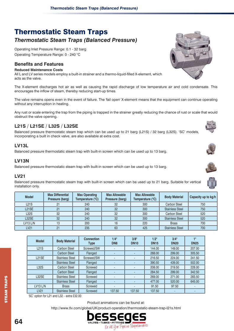
Thermostatic Steam Traps (Balanced Pressure)S
TE
AM
TR
AP
S
Thermostatic Steam TrapsThermostatic Steam Traps (Balanced Pressure)
Operating Inlet Pressure Range: 0.1 - 32 barg
Operating Temperature Range: 0 - 240 °C
Benefits and FeaturesReduced Maintenance CostsAll L and LV series models employ a built-in strainer and a thermo-liquid-filled X-element, which acts as the valve.
The X-element discharges hot air as well as causing the rapid discharge of low temperature air and cold condensate. This encourages the inflow of steam, thereby reducing start-up times.
The valve remains opens even in the event of failure. The 'fail open' X-element means that the equipment can continue operating without any interruption in heating.
Any rust or scale entering the trap from the piping is trapped in the strainer greatly reducing the chance of rust or scale that would obstruct the valve opening.
L21S / L21SE / L32S / L32SE Balanced pressure thermostatic steam trap which can be used up to 21 barg (L21S) / 32 barg (L32S). ‘SC’ models, incorporating a built in check valve, are also available at extra cost.
LV13L Balanced pressure thermostatic steam trap with built-in screen which can be used up to 13 barg.
LV13N Balanced pressure thermostatic steam trap with built-in screen which can be used up to 13 barg.
LV21 Balanced pressure thermostatic steam trap with built-in screen which can be used up to 21 barg. Suitable for vertical installation only.
ModelMax Differential Pressure (barg)
Max Operating Temperature (°C)
Max Allowable Pressure (barg)
Max Allowable Temperature (°C)
Body Material Capacity up to kg/h
L21S 21 240 32 300 Carbon Steel 750L21SE 21 240 32 300 Stainless Steel 750L32S 32 240 32 300 Carbon Steel 520
L32SE 32 240 32 300 Stainless Steel 520LV13 L/N 13 200 16 220 Brass 700
LV21 21 235 63 425 Stainless Steel 700
Model Body MaterialConnection
Type1/4" DN8
3/8" DN10
1/2" DN15
3/4" DN20
1" DN25
L21S Carbon Steel Screwed/SW - - 144.00 149.00 207.00Carbon Steel Flanged - - 268.00 299.00 305.50
L21SE Stainless Steel Screwed/SW - - 216.50 224.00 241.50Stainless Steel Flanged - - 390.50 439.00 502.00
L32S Carbon Steel Screwed - - 208.00 219.50 228.00Carbon Steel Flanged - - 284.50 299.00 342.50
L32SE Stainless Steel Screwed - - 269.00 271.00 283.50Stainless Steel Flanged - - 477.00 520.00 645.00
LV13 L/N Brass Screwed - - 91.50 97.50 -LV21 Stainless Steel Screwed 137.50 137.50 137.50 - -
‘SC’ option for L21 and L32 – extra £32.00
Product animations can be found at:
http://www.tlv.com/global/UK/product-operation/thermostatic-steam-trap-l21s.html
64
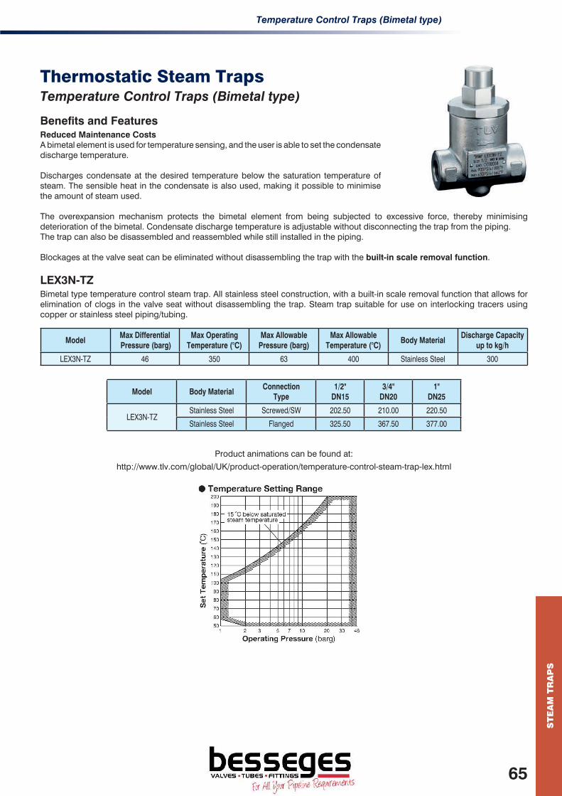
Temperature Control Traps (Bimetal type)
ST
EA
M T
RA
PS
Thermostatic Steam TrapsTemperature Control Traps (Bimetal type)
Benefits and FeaturesReduced Maintenance CostsA bimetal element is used for temperature sensing, and the user is able to set the condensate discharge temperature.
Discharges condensate at the desired temperature below the saturation temperature of steam. The sensible heat in the condensate is also used, making it possible to minimise the amount of steam used.
The overexpansion mechanism protects the bimetal element from being subjected to excessive force, thereby minimising deterioration of the bimetal. Condensate discharge temperature is adjustable without disconnecting the trap from the piping.The trap can also be disassembled and reassembled while still installed in the piping.
Blockages at the valve seat can be eliminated without disassembling the trap with the built-in scale removal function.
LEX3N-TZ Bimetal type temperature control steam trap. All stainless steel construction, with a built-in scale removal function that allows for elimination of clogs in the valve seat without disassembling the trap. Steam trap suitable for use on interlocking tracers using copper or stainless steel piping/tubing.
ModelMax Differential Pressure (barg)
Max Operating Temperature (°C)
Max Allowable Pressure (barg)
Max Allowable Temperature (°C)
Body MaterialDischarge Capacity
up to kg/h
LEX3N-TZ 46 350 63 400 Stainless Steel 300
Model Body MaterialConnection
Type1/2"
DN153/4"
DN201"
DN25
LEX3N-TZStainless Steel Screwed/SW 202.50 210.00 220.50
Stainless Steel Flanged 325.50 367.50 377.00
Product animations can be found at:
http://www.tlv.com/global/UK/product-operation/temperature-control-steam-trap-lex.html
65

Steam Traps S
TE
AM
TR
AP
S
Clean Steam TrapsSteam Traps Clean steam traps designed to allow complete condensate drainage and easy disassembly and cleaning.
Operating Inlet Pressure Range: 0.1 - 6 barg
Operating Temperature Range: 0 - 165 °C
Benefits and FeaturesReduced Maintenance CostsThe interior of these steam traps are designed to prevent corrosion and growth of bacteria. All components are stainless steel.
X-elementThe X-element discharges hot air as well as causing the rapid discharge of low temperature air and cold condensate. This encourages the inflow of steam, thereby reducing start-up times.
Clamp connection at the joint allows for easy disassembly and cleaning.
Range of Products to Meet the Required Cleanliness LevelInterior and exterior surfaces of the steam trap are available in three classes, natural machining, fine machining and buff-polishing. Models are also available with electro-polished surfaces for further improvement to prevent bacterial growth.
SS3PFree float type clean steam trap. Crevice-free design allows for condensate drainage without pooling. Internal finishes available are SS3E – 25µm Ra electro-polished, SS3P – 0.8µm Ra buff-polished or 25µm Ra electro-polished and SS3ER – buff polished and then 0.4µm Ra electro-polished.
SS5P Free float type clean steam trap. Crevice-free design allows for condensate drainage without pooling. Internal finish – buff polished 0.8µm Ra. 0.4µm Ra finish also available.
VS3PFree float tyype liquid air vent. Precision-ground float, three-point seating and valve seat with rubber ensures superior sealing. Internal finishes available are VS3E – 25µm Ra electro-polished, VS3P – 0.8µm Ra buff polished or 25µm Ra electro-polished and VS3EP – buff polished and then 0.4µm Ra electro-polished.
LV6Thermostatic steam traps for clean steam. Virtually crevice-free design allows for condensate drainage without pooling. Internal finishes available are LV6CE – Natural Machining, LV6SF – Fine Machining 0.8µm Ra, LV6P – Polished 0.8µm Ra. LV6EP 0.4µm Ra finish also available. Bodies supplied with tri-clamp or tube end connections.
ModelMax Differential Pressure (barg)
Max Operating Temperature (°C)
Max Allowable Pressure (barg)
Max Allowable Temperature (°C)
Body MaterialDischarge Capacity
up to kg/h
SS5P 6 165 10 185 Stainless Steel 510
LV6 6 165 10 185 Stainless Steel 780
SS3P 6 165 10 185 Stainless Steel 170
VS3P 6 100 10 185 Stainless Steel 120
Model Body MaterialConnection
Type1/2"
DN153/4"
DN201"
DN25
SS3P^* Stainless Steel Tri clamp 713.00 732.00 -
SS5P^ Stainless Steel Tri clamp - - 938.00
LV6CE Stainless Steel Tri clamp / Tube end 302.50 325.50 341.50
LV6SF Stainless Steel Tri clamp / Tube end 491.50 510.50 593.50
LV6P Stainless Steel Tri clamp / Tube end 630.00 648.00 779.00
VS3P* Stainless Steel Tri clamp 713.00 732.00 -
^ Tube connections available on request * Different surface finishes are available.
66

Steam Traps
ST
EA
M T
RA
PS
QuickTrapsSteam Traps
Operating Inlet Pressure Range: 0.1 - 46 barg
Operating Temperature Range: 0 - 425 °C
Benefits and FeaturesReduced Maintenance Costs
TLV QuickTrap two-bolt system will enable the most inexperienced personnel to easily replace a steam trap in minutes.
Also the design of the universal flange permits the installation of a steam trap in the correct position regardless of the piping installation.
Connections for the Steam Traps and the Stations are universal; therefore traps can be interchanged for different types and manufactures.
Please note: the steam trap and stations are bought separately.
S3 / S5 / S5H QuickTrap® Free Flow Steam Traps. Free float trap for use on steam mains.
QuickTrap connections allow for inline replacement. Can be used on either vertical or horizontal pipelines.
P46UC/P46UC-Y QuickTrap® Thermodynamic Steam Traps. Can be used up to 46 barg. Integral universal flange allows for inline replacement. Air-jacketing insulates and reduces the influence of harsh environmental conditions. Stainless steel body. The P46UC-Y steam trap integrates a screen to the traps body making it suitable for connectors that do not have a screen built in the connector body.
L32 QuickTrap® Thermostatic Steam Traps. Can be used up to 32 barg. Universal flange allows for inline replacement. Trap cover is carbon steel. Body and connector body are stainless steel.
ModelMax Operating Pressure (barg)
Max Operating Temperature (°C)
Max Allowable Pressure (barg)
Max Allowable Temperature (°C)
Body MaterialDischarge Capacity
up to kg/h
S3^ 5, 10, 21 400 21 400 Stainless Steel 310
S5^ 5, 10, 21, 32 400 32 400 Stainless Steel 800
S5H^ 46 425 46 425 Stainless Steel 800
P46UC^ 46 400 46 400 Stainless Steel 740
L32^ 32 240 32 300 Stainless Steel 520
^Requires Universal Connector in addition unless compatible connector is already installed.
Model Body MaterialConnection
TypePrice
S3^ Stainless Steel Universal 201.50
S5^ Stainless Steel Universal 365.50
S5H^ Stainless Steel Universal 455.00
P46UC^ Stainless Steel Universal 153.50
P46UC-Y^ Stainless Steel Universal 209.00
L32^ Stainless Steel Universal 174.50
^Requires F46 Universal Connector (page 117) in addition unless compatible connector is already installed.
67

Trap StationsS
TE
AM
TR
AP
S
QuickTrapsTrap Stations
Operating Inlet Pressure Range: 0.1 - 46 barg
Operating Temperature Range: 0 - 425 °C
Benefits and FeaturesReduced Maintenance Costs
TLV QuickTrap two-bolt system allows for easy replacement of a steam trap in minutes. Guidance on the correct installation can be found in the Operation and Maintenance Manual.
Also, the design of the universal flange permits the installation of a steam trap in the correct position regardless of the piping installation.
Connections for the steam traps and the stations are universal; therefore traps can be interchanged for different types and manufacturers.
Please note: the steam trap and stations are supplied separately.
F46 Stainless steel trap in-line connector with in-built strainer. The station is from the QuickTrap series, which makes conversion and installation easy. The QuickTrap connection is universal and different types and other manufacturers’ traps can be interchanged.
When used with the S3 and S5, the combination is referred to as the FS3 and FS5 respectively. This is similar for the P46UC and L32 which are referred to as FP46UC and FL32 respectively. Also available in male thread “union” connection (F46UN) and pipe end connection (F46UN-P).
V1 / V2 SeriesStainless steel trap station incorporating bellows sealed valves. The station is from the QuickTrap series, which makes conversion between types of traps and installation easy. The QuickTrap connection is universal and different types and different manufacturers’ traps can be interchanged.
The stations are ‘handed’ (RB / LB) and direction of flow should be advised at time of placing order.
V1 incorporates one valve at the trap inlet whilst V2 incorporates 2 valves at the inlet and the outlet of the trap.
Model V1-RB V1-LB V2-RB V2-LB
Flow direction
ModelMax Operating Pressure (barg)
Max Operating Temperature (°C)
Max Allowable Pressure (barg)
Max Allowable Temperature (°C)
Body Material
F46 46 ª 425 ª 46 425 Stainless SteelV1 46 ª 400 ª 46 400 Stainless SteelV2 46 ª 400 ª 46 400 Stainless Steel
ª Actual condition limitation is governed by trap selection
Model Body MaterialConnection
Type1/2"
DN153/4"
DN201"
DN25
F46Stainless Steel Screwed/SW 92.50 93.50 167.00Stainless Steel Flanged 211.00 228.00 290.00Stainless Steel Pipe ends 163.00 167.00 197.50
F46UN Stainless Steel Union (male thread) 120.00 120.00 182.00F46UN-P Stainless Steel Pipe end 168.00 169.00 236.00
V1^ Stainless Steel Screwed/SW 367.50 479.00 -V2^ Stainless Steel Screwed/SW 629.00 645.00 -
^ Other connection standards available.* Unit shown is the FP46UC.
*
68

CO
ND
EN
SA
TE
RE
CO
VE
RY
Condensate Recovery EquipmentSummaryPresenting condensate recovery pumps.
Offering products suitable for use on high-lift closed recovery applications and applications involving mechanical pumps where the use of electric power is not possible. Equipment for recovering and transporting condensate even in negative differential situations, without cavitation issues..
GT PowerTrap® (Mechanical Pump with Built-in Trap) Condensate recovery pump with integral trap requiring no electricity.
GP PowerTrap® (Mechanical Pump) Condensate recovery pumps requiring no electricity.
Packaged Pump SystemsComplete pre-fabricated packages requiring no electricity.
Benefits and Features A broad line-up of optimised condensate recovery equipment, to suit each condensate recovery application and capacity.
Comprehensive consulting services for optimised condensate recovery systems, including onsite surveys, measures to ensure water quality, system design, pipeline construction, and confirmation of results.
Application Areas Recovers high temperature condensate and delivers it to another location.
Collects, removes and transports condensate that has accumulated inside the equipment.
69

GT PowerTrap® (Mechanical Pump with Built-in Trap & Check Valves)C
ON
DE
NS
AT
E R
EC
OV
ER
Y
Condensate Recovery EquipmentGT PowerTrap® (Mechanical Pump with Built-in Trap & Check Valves)
Operating Pressure Range: Vacuum - 14 barg
Operating Temperature Range: 0 - 220 °C
Benefits and FeaturesRecovers and pumps condensate in order to recycle heat energy and water resources. The snap-action mechanism rapidly switches between sending condensate to the mechanical pump and preventing delay-induced leakage of motive medium (steam/air).
Steam using equipment utilising control valves, have a tendency to suffer from the 'stall' phenomenon. This results in process temperature swings, water hammer or tube corrosion. By installing PowerTrap® this stall phenomenon can be prevented. The GT series has an integral steam trap, making it suitable for condensate recovery from equipment that experiences fluctuations in pressure from negative to positive pressure.
The unit is powered by steam or air, so there is no need for electrical facilities, which makes it suitable for use in hazardous area installations. They are designed to allow maintenance without being removed from condensate recovery lines.
GT5C Most compact mechanical Pump/Trap with lowest filling head.
GT10LThis is the compact version of the GT10. Requires a lower filling head than the GT10.
GT14L/GT14MThis compact version of the GT14 and can operate with a low filling head (min. 300mm (GT14L),350 mm(GT14M)).
GT10/GT14 High capacity version for larger loads. Minimum filling head of 710mm.
ModelMax Operating Pressure (barg)
Max Operating Temperature (°C)
Max Allowable Pressure (barg)
Max Allowable Temperature (°C)
Body MaterialCapacity up to kg/h
Pump TrappingGT5C 5 185 8 200 Cast Iron / Stainless Steel 250* 1,000
GT10L 10.5 185 13 (CI)/21 (CS/SS) 200 (CI)/220 (CS/SS)Cast Iron / Cast Steel /
Stainless Steel1,4450 10,000
GT10 10.5 185 13 (CI)/16 (CS/SS) 200 (CI)/220 (CS/SS)Cast Iron / Cast Steel /
Stainless Steel8,200 35,000
GT14L 13 200 13(CI) 200(CI) Cast Iron 2,200 14,000
GT14M 13 220 14 220 Cast Steel / Stainless Steel 3,200 15,000
GT14 14 200 16 220 Cast Steel 5,500 35,000
* Please refer to specification data sheets / consult TLV for your applicaiton.
Model Body MaterialConnection
Type1" x 1"
DN25 x 251 1/2" x 1" DN40 x 25
1 1/2" x 1 1/2" DN40 x 40
2" x 2" DN50 x 50
3" x 2" DN80 x 50
GT5CCast Iron Screwed / Flanged 1,372.50 - - - -
Stainless Steel Screwed / Flanged 2,485.50 - - - -
GT10L
Cast Iron Screwed 2,461.00 2,839.00 - - -
Cast Steel Screwed 3,379.00 4,046.00 - - -
Stainless Steel Screwed 5,222.00 5,909.50 - - -
GT10Cast Iron Screwed / Flanged - - - - 6,814.50
Cast Steel Screwed - - - - 8,365.50
GT14L Cast Steel Flanged - 4,474.00 - - -
GT14MCast Iron Screwed - - 6,202.50 - -
Stainless Steel Flanged - - 7,026.50 - -
GT14 Cast Steel Flanged - - - 8,635.00 8,635.00
70
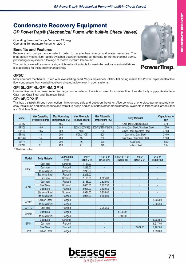
GP PowerTrap® (Mechanical Pump with built-in Check Valves)
CO
ND
EN
SA
TE
RE
CO
VE
RY
Condensate Recovery EquipmentGP PowerTrap® (Mechanical Pump with built-in Check Valves)
Operating Pressure Range: Vacuum - 21 bargOperating Temperature Range: 0 - 220 °C
Benefits and FeaturesRecovers and pumps condensate in order to recycle heat energy and water resources. The snap-action mechanism rapidly switches between sending condensate to the mechanical pump, preventing delay-induced leakage of motive medium (steam/air).
The unit is powered by steam or air, which makes it suitable for use in hazardous area installations. It is designed for insitu maintenance lines.
GP5CMost compact mechanical Pump with lowest filling head. Very simple linear inlet/outlet piping makes this PowerTrap® ideal for low flow condensate from vented receivers situated at low level in open systems.
GP10L/GP14L/GP14M/GP14Uses motive medium pressure to discharge condensate, so there is no need for construction of an electricity supply. Available in Cast Iron, Cast Steel and Stainless Steel.
GP10F/GP21F This has a straight through connection - inlet on one side and outlet on the other. Also consists of one-piece pump assembly for easy installation and maintenance and retrofit to pump bodies of certain other manufacturers. Available in fabricated Carbon Steel and Stainless Steel.
ModelMax Operating Pressure (barg)
Max Operating Temperature (°C)
Max Allowable Pressure (barg)
Max Allowable Temperature (°C)
Body MaterialCapacity up to
kg/hGP5C 5 185 10 200 Cast Iron / Stainless Steel 270GP10L 10.5 185 13(CI)/21(CS/SS) 200(CI)/220(CS/SS) Cast Iron / Cast Steel /Stainless Steel 1,500GP10F 10.5 220 10.5 220 Carbon Steel /Stainless Steel 7,500GP14L 13 200 13(CI)/21(CS) 200 Cast Iron / Cast Steel 2,400GP14M 14 200 13 200 Cast Steel / Stainless Steel 5,500GP14 14 200 16 220 Cast Steel 6,00
GP21F 21 220 21 220 Carbon Steel 8,5--* Cast steel option
Model Body Material Connection Type
1" x 1" DN25 x 25
1 1/2" x 1" DN40 x 25
1 1/2" x 1 1/2" DN40 x 40
2" x 2" DN50 x 50
3" x 2" DN80 x 50
GP5C
Cast Iron Screwed 1,157.00 - - - -Cast Iron Flanged 1,296.00 - - - -
Stainless Steel Screwed 2,248.00 - - - -Stainless Steel Flanged 2,293.00 - - - -
GP10L
Cast Iron Screwed 2,166.00 2,525.00 - - -Cast Iron Flanged 2,166.00 2,525.00 - - -Cast Steel Screwed 3,005.00 3,622.50 - - -Cast Steel Flanged 3,005.00 3,622.50 - - -
Stainless Steel Screwed 4,934.00 5,858.00 - - -Stainless Steel Flanged 4,934.00 5,858.00 - - -
GP10FCarbon Steel Flanged - - - - 4,005.00
Stainless Steel Flanged - - - - 7,925.50GP14L Cast Iron Flanged - 3,265.50 - - -
GP14MCast Steel Flanged - - 4,208.50 - -
Stainless Steel Flanged - - 6,840.00 - -
GP14Cast Steel Screwed - - - - 6,203.50Cast Iron Flanged - - - - 6,517.00Cast Steel Flanged - - - 7,021.00 7,162.00
GP21 Carbon Steel Flanged - - - 6,650.00
71

Packaged Pump SystemsC
ON
DE
NS
AT
E R
EC
OV
ER
Y
Condensate Recovery EquipmentPackaged Pump Systems
Benefits and FeaturesComplete package for the return of condensate from process area to hotwell. Simple selection and installation with compact design to ensure efficient use of available floor space.
Interconnecting pipe work and receiver also included. Primed and painted finish. Stainless steel option also available.
Improved energy efficiency by using the residual heat energy of the condensate to maintain the hotwell temperature.
Available with receiver constructed from either Steel or Stainless Steel (dependent on model selected) and also with a duty/stand-by or full duplex (parallel operating) option.
All models are intrinsically safe.
GP10L / GP14L / GP14M Packaged Pump SystemAutomatic steam operated mechanical pump system.
Complete system including; inlet and outlet check valves, motive steam isolation valve and strainer, exhaust pipe steam isolsation valve and motive steam trap.
Mounted on a common carbon steel frame. Interconnecting pipework and receiver also included. Primed and painted finish. Stainless steel options also available.
GP10F Packaged Pump SystemAutomatic steam operated carbon steel mechanical pump (GP10F) system. Capacity up to 8,000 kg/h.
Complete systems including; inlet and outlet check valves, motive steam isolation valve and strainer, exhaust steam isolation valve and motive steam trap.
All connections are flanged and mounted on a common carbon steel frame. Interconnecting pipe work and receiver also included. Primed and painted finish. Stainless Steel option also available.
ModelMax Operating Pressure (barg)
Max Operating Temperature (°C)
Max Allowable Pressure (barg)
Max Allowable Temperature (°C)
Body MaterialCapacity p to
kg/h
GP10L 10.5 185 13(CS)/21(CS) 200 / 220 Cast Iron / Cast Steel 1,800
GP14L 14 220 14 220 Cast Iron / Cast Steel 2,400
GP14M 13 / 14 200 / 220* 13 / 21 200 / 220* Cast Iron / Cast Steel 4,000
GP10F Package 10.5 220 10.5 220 Carbon Steel / Stainless Steel 8,000
* Depending on the GP14M Body Material selection.
Model Body MaterialConnection
Type1" x 1"
DN25 x 251 1/2" x 1" DN40 x 25
3" x 2" DN80 x 50
GL10L Cast Iron Screwed / Flanged 5,045.00 5,884.00 -
Cast Steel Screwed / Flanged 6,450.00 7,289.00 -
GP14LCast Iron Flanged - 7,324.00 -
Cast Steel Flanged - 11,570.00 -
GP10FCarbon Steel Flanged - - 8,567.00
Stainless Steel Flanged - - 15,607.00Options
(additional cost to base price, for Carbon Steel model only*)Duty/Stand-by - - - - 5,218.50
Full Duplex - - - - 7,323.00
* For different material options contact TLV
72

HeatPacks
PA
CK
AG
ED
SO
LU
TIO
NS
Packaged SolutionsHeatPacksPresenting TLV Packaged HeatPack solutions.
Operating Inlet Pressure Range: 0.1 – 7.5 barg Heat Load: 75 – 2350 kW
Benefits and FeaturesHeatPack heat exchanger systems are designed, manufactured, tested and supplied in accordance with TLV Euro Engineering UK Ltd material, component and assembly specifications. Units are designed with a small footprint to deliver the rated output within agreed parameters and can be connected with BMS.
Domestic Hot Water (DHW)• The packaged unit delivers a constant, stable temperature supply of hot water, even with sudden and
large load fluctuations found in domestic hot water systems.• An integrated shunt pump ensures residual heat is removed from the heat exchanger during low-load situations providing
protection against pressurisation due to boiling-off of the secondary fluid.
Low Temperature Hot Water (LTHW)• The packaged unit ensures accurate control of temperature whatever the heating load requirement.• Unit responds exceptionally well to changes in load throughout the heating circuits.
Tube HeatReady to install free standing fabricated package. Incorporates stainless steel tubular heat exchanger, tailored to meet given load and pressure criteria, with stainless steel primary and secondary pipework.
Utilises fast acting electric or pneumatic actuated control valve with PID microprocessor controller with PT100 sensor complete with touch screen display. Optional pumped condensate removal system.
Available with cast iron, ductile cast iron and cast steel ancillary components.
Plate HeatReady to install free standing fabricated package. Incorporates a stainless steel plate heat exchanger, tailored to meet your given load criteria, with stainless steel primary and secondary pipework.
Utilises fast acting electric or pneumatic actuated control valve with PID microprocessor controller and PT100 sensor complete with touch screen display. Optional pumped condensate removal system.
Available with cast iron, ductile cast iron and cast steel ancillary components.
Package DesignatorTube Heat Exchanger Plate Heat Exchanger
Heat Load (kW)Min Max Min Max
A 110 185 75 120B 185 295 120 195C 295 475 195 300D 475 750 300 490E 750 1150 490 750F 1150 1600 750 1025G 1600 2350 1025 1525
Steam Supply Pressure 7.5 barg to 5 barg 4.5 barg to 3 barg
Units are fully compliant with PER, and CE marked where appropriate.
Standard Package Designators
E.g. TH D-LTHW-EL-ST-SGIHeat Exchanger
TypePackage
Designator (Size)Application Control Valve
Steam Trap Option
Ancillary Component Body Material
TH Tube Heat
Letter (A-G)DHW
Domestic Hot WaterEL
ElectricalST
Steam TrapCI
Cast IronPH
Plate HeatLTHW
Low Temp Hot WaterPN
PneumaticGT
Pumped TrapSGI
Ductile Cast Iron
PoR PoR PoR PoRCS
Cast Steel
73
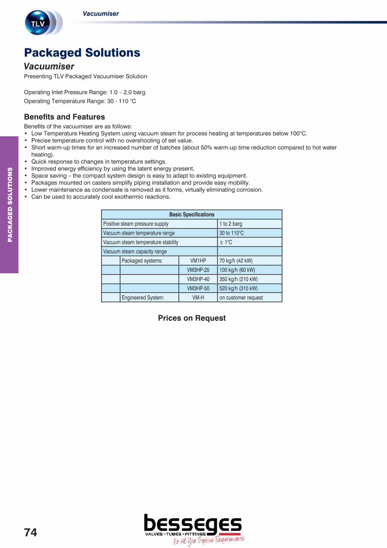
VacuumiserP
AC
KA
GE
D S
OLU
TIO
NS
Packaged SolutionsVacuumiserPresenting TLV Packaged Vacuumiser Solution
Operating Inlet Pressure Range: 1.0 – 2.0 barg
Operating Temperature Range: 30 - 110 °C
Benefits and FeaturesBenefits of the vacuumiser are as follows:• Low Temperature Heating System using vacuum steam for process heating at temperatures below 100°C.• Precise temperature control with no overshooting of set value.• Short warm-up times for an increased number of batches (about 50% warm-up time reduction compared to hot water
heating).• Quick response to changes in temperature settings.• Improved energy efficiency by using the latent energy present.• Space saving – the compact system design is easy to adapt to existing equipment.• Packages mounted on casters simplify piping installation and provide easy mobility.• Lower maintenance as condensate is removed as it forms, virtually eliminating corrosion.• Can be used to accurately cool exothermic reactions.
Basic Specifications
Positive steam pressure supply 1 to 2 barg
Vacuum steam temperature range 30 to 110°C
Vacuum steam temperature stability ± 1°C
Vacuum steam capacity range
Packaged systems: VM1HP 70 kg/h (42 kW)
VM3HP-25 100 kg/h (60 kW)
VM3HP-40 350 kg/h (210 kW)
VM3HP-50 520 kg/h (310 kW)
Engineered System: VM-H on customer request
Prices on Request
74
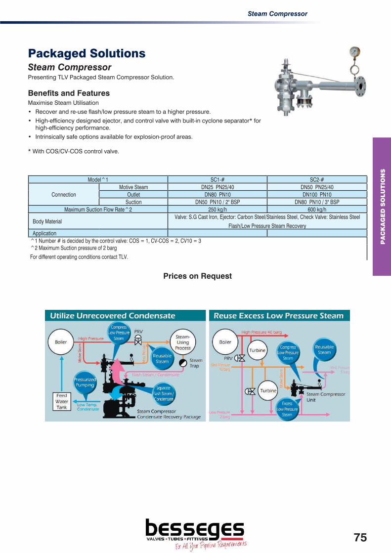
Steam Compressor
PA
CK
AG
ED
SO
LU
TIO
NS
Packaged SolutionsSteam CompressorPresenting TLV Packaged Steam Compressor Solution.
Benefits and FeaturesMaximise Steam Utilisation
• Recover and re-use flash/low pressure steam to a higher pressure.
• High-efficiency designed ejector, and control valve with built-in cyclone separator* for high-efficiency performance.
• Intrinsically safe options available for explosion-proof areas.
* With COS/CV-COS control valve.
Model^1 SC1-# SC2-#
ConnectionMotive Steam DN25 PN25/40 DN50 PN25/40
Outlet DN80 PN10 DN100 PN10Suction DN50 PN10 / 2" BSP DN80 PN10 / 3" BSP
Maximum Suction Flow Rate^2 250 kg/h 600 kg/h
Body MaterialValve: S.G Cast Iron, Ejector: Carbon Steel/Stainless Steel, Check Valve: Stainless Steel
Flash/Low Pressure Steam Recovery Application^1 Number # is decided by the control valve: COS = 1, CV-COS = 2, CV10 = 3 ^2 Maximum Suction pressure of 2 barg
For different operating conditions contact TLV.
Prices on Request
75

Manifolds and Trap Stations
MA
NIF
OLD
S
ManifoldsManifolds and Trap StationsPresenting manifolds suitable for use on steam supply branches and for convergence of condensate from trace lines etc.
Operating Pressure Range: 0 - 50 bargOperating Temperature Range: 0 - 400 °C
Benefits and FeaturesThe simple installation of a manifold to steam or condensate piping often reduces the labour necessary for both design and piping construction. By packaging valves and steam traps together, a manifold offers optimisation of management. Inspection and maintenance are easy after installation.
The manifolds for condensate collection can accommodate various types of steam traps with the QuickTrap design.
ManifoldsSM / CMForged steel manifold with maintainable built in bellows sealed valves suitable for use on trace line branches or where trap outlet piping meets. Line-up features manifold body with inlet isolation valves with or without optional extras. Nominal bore of manifold is 40mm. Customised design to meet customer’s need.
SM - Steam Manifold, Individual manifold complete with upstream steam inlet valve, and steam trap connector and isolation valve on the manifold drain. Comes in option of 4 (SM4), 8 (SM8) or 12 (SM12) branch models.
CM - Condensate Manifold, Individual manifold complete with V1 trap stations on condensate inlets, bellows sealed valve on condensate outlet and blow-off valve on manifold base. Comes in option of 4 (CM4), 8 (CM8) or 12 (CM12) branch models.
All items come preassembled.
Trap StationsV1 / V2 SeriesStainless steel trap station incorporating bellows sealed valve. Steam trap station compatible with all steam traps from the QuickTrap series, which makes conversion and installation easy. Standard connection is BSP screwed or socket weld. V1 / V2 can be supplied with optional stub pipe ends for Lok-ring connection technology.
^NB: Traps not included
ModelMax Operating Pressure (barg)
Max Operating Temperature (°C)
Max Allowable Pressure (barg)
Max Allowable Temperature (°C)
Body Material
SM4/SM8/SM12 50* 400^ 57 425 Carbon SteelCM4/CM8/CM12 50* 400^ 57 425 Carbon Steel
V1 46* 400^ 46 400 Stainless SteelV2 46* 400^ 46 400 Stainless Steel
^ Restrictions to traps used
Manifolds
4 Branch Manifold 8 Branch Manifold 12 Branch Manifold
Model Body MaterialConnection
Type1/2"
DN153/4"
DN201/2"
DN153/4"
DN201/2"
DN153/4"
DN20
Steam Manifold^ Carbon Steel Socket WeldSM4
2,412.00SM4
2,421.50SM8
3,252.00SM8
3,745.50SM12
4,977.00SM12
5,011.00Condensate Manifold^
Carbon Steel Socket WeldCM4
3,613.00CM4
3,691.00CM8
6,213.00CM8
6,251.00CM12
8,821.00CM12
8,901.00Trap Stations
1/2" 3/4"
V1 Stainless Steel Screwed / SW 367.50 479.00
V2 Stainless Steel Screwed / SW 629.00 645.00
Pipe end for Lockrings for V1 / V2 97.00
77

PT1 Pocket TrapMan
MA
INT
EN
AN
CE
IN
ST
RU
ME
NT
S
Maintenance InstrumentsPT1 Pocket TrapManPortable diagnostic tool suitable for small sites or random spot checks
Benefits and FeaturesDaily inspection tool used to measure vibration (ultrasound) and temperature, and for basic operational judgement of steam traps, valves and shaft bearings.
Takes a simultaneous ultrasonic and temperature reading. Compact design, easy to carry around in a pocket, also comes with removable earphones.
The band pass filter eliminates interference from ambient noises, resulting in high precision ultrasonic measurement.
Automatically gives a quick judgment of traps or valve leaks on air piping.
ModelMax Trap Surface Temperature (°C)
Price
PT1 350 1,469.00
79

PT1 Pocket TrapManM
AIN
TE
NA
NC
E I
NS
TR
UM
EN
TS
Steam Trap SurveysThe steam trap survey is a two step process.
Firstly, all steam traps within the scope of the survey are identified and catalogued. This is assisted by tagging each steam trap with sequentially numbered aluminium (or stainless steel) tags.
Secondly, the testing instrument will identify any steam trap which is faulty and in certain failure modes identify the intensity of the failure. Failure could include blocked traps, leaking traps, incorrect installation or accidental damage. From this data, a report is produced which estimates the actual cost of the leaking traps in terms of steam costs.
The instrument used to test the steam traps is a highly sophisticated hand held data logging device – the TLV TM5 TrapMan, which has been specifically designed and developed by TLV for the testing of steam traps. The unit is pre-programmed with the sonic foot print of over 5000 different steam trap models from all of the worlds’ major manufacturers at various steam pressures and operational statuses.
The engineer can be expected to test in the region of 60 to 100 steam traps in one working day (8 hours). Once all of the steam traps have been tested, the engineer will then download the data from the TM5 TrapMan into bespoke software to allow a report to be created. This report tabulates all steam traps tested including type, location, pressure, temperature, status, leak rate (if applicable) and can estimate the cost of steam losses due to any leaks. The software can be used to publish lists of trap failures, and produce various graphs including failure rate by trap type or manufacturer and estimated steam leakage costs.
A report will then be compiled, in addition to the survey test results, to include recommended steam traps that can be used to replace faulty units, and also a quotation for the replacement steam traps.
We recommend that steam trap surveys are carried out at least annually. Surveys detect steam leaks and correlating ‘costs’ of the leaks are detailed. The detection and rectification of steam leaks will usually offset the cost of the survey, whilst improving the efficiency of the plant and minimising environmental impacts. In many cases, reduction in energy use far outweighs cost of the survey and replacement steam traps.
80

CO
NS
ULT
AT
ION
& A
UD
ITIN
G S
ER
VIC
ES
Consultation and Auditing Services
Recent legislation by international organisations has seen a substantial increase in the awareness of global warming, the need to reduce carbon emissions from fossil fuels and to conserve energy. Whilst steam is one of the most efficient sources of heat energy used in modern processes, any plant which uses this medium must be regularly inspected and maintained to ensure that the equipment, which is crucial to the efficiency of the process plant, is operating correctly.
TLV offers a range of consultation and auditing services that do not only identify and suggest possible solutions to problems associated with steam systems but also quantifies the losses and offers solutions in order to reduce costs.
TLV’s services are as follows:
Steam System AuditThe Steam System Audit is a general steam system assessment and provides details of areas of concern.
Any cost savings, from steam losses, will be quantified wherever possible. At all times significant focus will be made onto health and safety issues to ensure safe operation of steam system. These proposed changes would be supported with detailed drawings of the areas requiring change. Assessments include any energy losses due to unlagged pipes and will also consider efficient equipment installation and process design.
Targeted Steam System AuditA more specific Steam System Audit, focusing on a specific issue within the plant. This may include, poor system performance, water hammer, areas of low pressures and fluctuating steam temperatures.
Engineers will carry out an analysis of the affected system and perform tests to correctly diagnose the problems. Results will be detailed in a written report and will include possible solutions to rectifying the problem.
Steam Energy AuditSteam Energy Audit will offer a check of steam systems with particular focus on steam losses and energy inefficiencies in plant users.
As such the audit will focus on boiler house equipment and condensate return systems. It will also include a comprehensive examination of process steam pressures and equipment design.
A full written report will be produced, with recommendations for improvements where possible. The report will contain a graphical analysis and quantify the inefficiencies in terms of costs.
Drawing FunctionDrawing Function offers TLV to create a CAD overlay on existing plant schematics showing accurate steam and condensate layout. If adjustment to the site installation is necessary, we can include before and after drawings if required.
PricesSurveys are bespoke to size and complexity of plant; proposals are calculated by a fixed daily rate with the exception of the Drawing Function where a fixed cost proposal will be offered after an initial site survey.
Please contact TLV to discuss your site requirements.
81

S
TE
AM
& C
ON
DE
NS
AT
E
TR
AIN
ING
SE
MIN
ER
S
Steam and Condensate Training Seminars
Every month TLV trains hundreds of steam users worldwide either in TLV Classrooms or on-site on best practice methods to manage steam and condensate systems.
More than 300 workshops and seminars are held annually, covering topics such as steam basics, trapping principals & applications, and effective energy utilization. For advanced steam users, training on steam and condensate piping design, control theory and waste heat management is also available.
Special workshops are also organized where plant managers and other key personnel are invited to exchange opinions and discuss new ways of optimizing their steam system.
Increase Your Expertise
Strengthen Your Skills
Create a strong foundation that strengthens problem-solving skills and enhances plant safety awareness by reviewing applied steam engineering principles.
Learn Through Experience
Learn interactively by manipulating product cross-sections and participating in live demonstrations that help visualize thermodynamic concepts.
Apply Your New KnowledgeDiscover new ways to reduce energy costs through case studies that help quantify energy and monetary savings, and then apply these principles to your system for improved efficiency.
2017 Seminar Schedule - EuropeTLV Euro Engineering offer a three-day steam training seminar with hands-on opportunities covering the efficient use of process steam through which you may achieve a Level 3 BTEC Advanced Award.
Topic Efficient Use of Process Steam
Winter Dates TBC
Schedule Summer Dates TBC
Autumn Dates TBC
The three-day seminar is followed by a two a written papers and an observation-based test to gain certification.
The seminars are held in English at TLV’s European headquarters in Germany.
BTEC syllabus• Fundamentals of steam and condensate
• System design, pipe sizing, valve sizing and best practice
• Steam trap testing, management and maintenance
• Improving efficiency and reducing losses
• Pressure reduction, temperature control and metering
• Trapping and condensate return
• Energy conservation and its recovery
On-site Seminars*On-site seminars are available to interested parties unable to attend courses held at the TLV training facilities. Qualified trainers can visit your factory and offer customized training tailored to the needs of your steam system.
* Seminar content and availability varies per location. For detailed information on training in your area, please contact us.
82

DO
CU
ME
NT
AT
ION
&
AP
PLIC
AT
ION
DR
AW
ING
S
DocumentationTest and Material Certificates
Description Price
PERFORMANCE TEST CERTIFICATE 45.00
CERTIFICATE OF CONFORMITY FOC
HYDROSTATIC PRESSURE TEST CERTIFICATE 45.00
MATERIAL CERTIFICATE BS EN10204-2.2 (CHARGED PER LINE ITEM) 45.00
MATERIAL CERTIFICATE BS EN10204-3.1 (CHARGED PER LINE ITEM) 85.00
CERTIFICATE OF ORIGIN 37.00
SET POINT CERTIFICATE FOR SAFETY VALVE FOC
PLEASE STATE ANY CERTIFICATION REQUIREMENTS WHEN PLACING AN ORDER.
RETROSPECTIVE SUPPLY OF CERTIFICATES MAY NOT BE POSSIBLE AND WILL INCUR ADDITIONAL COST.
83

DO
CU
ME
NT
AT
ION
&
AP
PLIC
AT
ION
DR
AW
ING
S
Application Drawings
On the following pages are typical installation drawings for steam applications. They include:
Steam Distribution System DrainageDraining Steam Mains-Free Float, Draining Steam Mains-Thermodynamic Steam Trap, Draining and Air Venting the Terminal Point of Steam Mains, Draining a Steam Header.
Pressure ControlLow Level Pressure Reducing Station, COSR Pressure Reducing Station, Series Pressure Reducing Valve Station for High Turndown Ratio, Parallel Pressure Reducing Valve Station for Wide Load Variations, Protection Critical Steam Supply With Surplussing Valve, COSPECT Pressure Reducing Station.
Temperature ControlBasic Tank Heating Coil, Plate Heat Exchanger, Shell and Tube Heat Exchanger, Prevention of Stall on a Shell and Tube Heat Exchangers.
Condensate and Flash Steam RecoverySteam Pipe Draining to a Manifold, Flash Vessel Installation, General Condensate Recovery System using GP10, Example of Flash Steam and Condensate Recovery from an Air Heater, Air Handling Unit – Gravitational Drainage (Zero Back Pressure), Air Handling Unit – Pumped Drainage (For High Level Condensate Recovery), Condensate Recovery from a Cylinder Dryer using a GP10 Power Trap.
Other Applications Boiling Pan (Fixed), Laundry Conditioning Tunnel, Multi-Roll Ironer, Platen Press, Plating Tank, Mill Roller and Cylinder Dryer, Space Heater, Sump Pit Waste Water Removal, Multi-Cylinder Dryer, Laundry Tumble Dryer, Small Ironer.
The following are provided as a guide only and professional advice should be sought before carrying out any installations. For any queries reference equipment suitability visit www.tlv.com or contact TLV’s Technical Sales Department.
85

D
OC
UM
EN
TA
TIO
N &
A
PP
LIC
AT
ION
DR
AW
ING
S
Steam Distribution System DrainageDraining Steam Mains-Free Float
Dwg No: A001-0102
TLV Stop Valve
TLV Free Float Steam Trap with Built-in Strainer and Air Vent
TLV Sight Glass
TLV Check Valve
Collection Leg and Dirt Pocket
Blowdown discharge. Pipe safely to drain.
To condensate return, drain or manifold.
B
1
2
3
4
A
C
NOTE: Drawing is not for installation purposes !
1 2 3 4 1
C
B
A
1
Steam Distribution System DrainageDraining Steam Mains-Thermodynamic Steam Trap
Dwg No: A002-0102
TLV Stop Valve
TLV Thermodynamic Steam Trap with Built-in Strainer and Air Vent
TLV Sight Glass
TLV Check Valve
Collection Leg and Dirt Pocket
Blowdown discharge. Pipe safely to drain.
The minimum distance should be 1 meter (3 feet).
B
1
2
3
4
A
C
To condensate return, drain or manifold.D
NOTE: Drawing is not for installation purposes !
1 2
B
A 3 4 1
D
C
1
86

DO
CU
ME
NT
AT
ION
&
AP
PLIC
AT
ION
DR
AW
ING
S
Steam Distribution System DrainageDraining and Air Venting the Terminal Point of Steam Mains
DWG No:A004-0102
A
B
1 3 4 5 1
D
1
2 5
1
TLV Stop Valve
TLV Air Vent With Built-in Strainer
TLV Free Float Steam Trap with Built-in Strainer and Air Vent
TLV Sight Glass
Collection Leg and Dirt Pocket
Blowdown discharge. Pipe safely to drain.
1
2
To condensate return, drain or manifold.
TLV Check Valve
B
3
4
A
D
5
NOTE: Drawing is not for installation purposes !
Steam Distribution System DrainageDraining a Steam Header
Dwg No:A005-0102
TLV Stop Valve
TLV Pressure Gauge
TLV Free Float Steam Trap with Built-in Strainer and Air Vent
TLV Sight Glass
1
3
4
2
TLV Check Valve
To condensate return, drain or manifold.A
5
NOTE: Drawing is not for installation purposes !
1
31 5
A
1
2
4
1
87

D
OC
UM
EN
TA
TIO
N &
A
PP
LIC
AT
ION
DR
AW
ING
S
Pressure ControlLow Level Pressure Reducing Station
Dwg No:B001-0102
TLV Stop Valve
TLV Pressure Gauge
TLV Strainer (installed in a 3 or 9 o'clock position)
TLV Pressure Reducing Valve
TLV Free Float Steam Trap with Built-in Strainer and Air
Vent
TLV Sight Glass
TLV Check Valve
TLV Pressure Safety Relief Valve
Vent (pipe to a safe area).
Drip Pan Elbow
Blowdown discharge. Pipe safely to drain.C
1
2
3
4
5
7
6
8
A
B
At least 10 pipe diameters is recommended.D
More than 15 pipe diameters, but at least
1 meter (3 feet) is recommended.
E
NOTE: The internal sensing line option is shown. Use with external sensing line is also possible.NOTE: Drawing is not for installation purposes !
1
2
4
1
2
8
1
5 7
6
1
3
1
1
C
C
A
B
E
D
1
5
6
7
1
Pressure ControlCOSR Pressure Reducing Station
Dwg No:B002-0102
5
3
2
1
4 TLV Pressure Reducing Valve
TLV Strainer (installed in a 3 or 9 o'clock position)
TLV Pressure Gauge
TLV Pressure Safety Relief Valve
TLV Stop Valve
A
D
B
C
Drip Pan Elbow
Vent (pipe to a safe area).
At least 10 pipe diameters is recommended.
More than 15 pipe diameters, but at least 1 meter
(3 feet) is recommended.
NOTE: Drawing is not for installation purposes !
2 31
A
B
C
D
2
4
1
5
NOTE: The internal sensing line option is shown. Use with external sensing line is also possible.
88

DO
CU
ME
NT
AT
ION
&
AP
PLIC
AT
ION
DR
AW
ING
S
Pressure ControlSeries Pressure Reducing Valve Station for High Turndown Ratio
Dwg No:B003-0102
TLV Pressure Gauge1
TLV Stop Valve
2
3
4
5
6
TLV Pressure Reducing Valve with Built-in
Strainer, Separator and Free Float Steam Trap
TLV Pressure Reducing Valve
TLV Pressure Safety Relief Valve
TLV Check Valve
A
B
C
D
E
F
To condensate return, drain or manifold.
At least 10 pipe diameters is recommended.
At least 30 pipe diameters is recommended.
Vent (pipe to a safe area).
Drip Pan Elbow
7
TLV Free Float Steam Trap with Built-in
Strainer and Air Vent
8
TLV Sight Glass
Blowdown discharge. Pipe safely to drain.
NOTE: Drawing is not for installation purposes !
12
3
1
4
2
1
5
6
2
A
C
E
F
G
B
D
A
2
6 7
2
8
2
G
At least 15 pipe diameters is recommended.
Pressure ControlParallel Pressure Reducing Valve Station for Wide Load Variations
Dwg No:B004-0102
NOTE: The safety valve should be sized to pass the capacity of the bypass plus both reducing valves in a fail full open mode.
1
2
3
4
5
TLV Pressure Gauge
TLV Stop Valve
TLV Pressure Reducing Valve with Built-in Strainer,
Separator and Free Float Steam Trap
TLV Check Valve
TLV Pressure Safety Relief Valve
At least 10 pipe diameters is recommended.
A
B
To condensate return, drain or manifold.
At least 15 pipe diameters is recommended.C
Vent (pipe to a safe area).D
Drip Pan ElbowE
Consider installation of a condensate drain
pocket and steam trap.
F
Consider installation of a condensate drain pocket and steam trap if piping rises.
G
NOTE: Drawing is not for installation purposes !
1
2
3
2
2
1
5
2
3
2
B
A
D
E
C
B
A
2
4
4
C
F
G
2
89

D
OC
UM
EN
TA
TIO
N &
A
PP
LIC
AT
ION
DR
AW
ING
S
Pressure ControlProtection Critical Steam Supply With Surplussing Valve
Dwg No:B005-0101
TLV Separator with Built-in Strainer and Steam
Trap
1
TLV Stop Valve
2
TLV Pressure Gauge
3
TLV Surplussing Valve
4
TLV Pressure Reducing Valve
5
TLV Pressure Safety Relief Valve
6
At least 10 pipe diameters is
recommended.
A
TLV Check Valve
7
NOTE: Drawing is not for installation purposes !
F
At least 15 pipe diameters is recommended.B
Vent (pipe to a safe area).
C
Drip Pan ElbowD
E
More than 15 pipe diameters, but at least1 meter (3 feet) is recommended.
Critical steam supply.
G Non critical steam supply.
H
To condensate return, drain or manifold.
F
B
B
B
A
2
4 3
2
3
G
1
7 2
H
2
2
6
C
D
3
E
5
Pressure ControlCOSPECT Pressure Reducing Station (Internal Sensing Line)
Dwg No:B006-0102
TLV Pressure Gauge
1
NOTE: An internal sensing line is shown. Use withexternal sensing line is also possible.
TLV Check Valve5
TLV Pressure Safety Relief Valve4
TLV Stop Valve
2
TLV Pressure Reducing Valve with Built-in Strainer,
Separator and Free Float Steam Trap
3
NOTE: Drawing is not for installation purposes !
At least 10 pipe diameters is recommended.A
Vent (pipe to a safe area).
D
Drip Pan Elbow
E
To condensate return, drain or manifold.
B
At least 15 pipe diameters is recommended.
C
1
2
3
2
2
4
A
B
C
D
E
3
5
90

DO
CU
ME
NT
AT
ION
&
AP
PLIC
AT
ION
DR
AW
ING
S
Temperature ControlBasic Tank Heating Coil
Dwg No:C001-0102
TLV Stop Valve
TLV Check Valve
TLV Sight Glass
TLV Free Float Steam Trap with Built-in Strainer and Air Vent
TLV Pressure Gauge
1
2
3
4
5
TLV Strainer (installed in a 3 or 9 o'clock position)
TLV Self Acting Temperature Regulator
TLV Vacuum Breaker
TLV Temperature Gauge
To condensate return, drain or manifold.A
7
6
8
9
NOTE: Drawing is not for installation purposes !
1
2
3 4 1
1 5 76
8
9
A
A
51 4 3 2 1
1
Temperature ControlPlate Heat Exchanger
Dwg No:C004-0102
TLV Stop Valve
TLV Pressure GaugeTLV Pressure Reducing Valve with Built-in Strainer, Separator and Free Float Steam TrapTLV Pressure Safety Relief Valve
TLV Check Valve
TLV Vacuum Breaker
TLV Controller
TLV Control Valve with I/P Converter and PositionerTLV Free Float Steam Trap with Built-in Strainer and Air Vent
TLV Sight Glass
TLV Temperature Sensor
10
1
2
3
4
5
7
6
8
9
At least 10 pipe diameters is recommended.A
11
At least 15 pipe diameters is recommended.B
Drip Pan ElbowC
Vent (pipe to a safe area).D
To condensate return, drain or manifold.E
NOTE: Drawing is not for installation purposes !
Blowdown discharge. Pipe safely to drain.F
E
1
1
12 1
3
2
4
C
D
E
1
5
5 1
E
F
7
8
1
91
11
10
1
1 9
1
5
10
A B
6
1
91

D
OC
UM
EN
TA
TIO
N &
A
PP
LIC
AT
ION
DR
AW
ING
S
Dwg No:C005-1020TLV Stop Valve2
TLV Pressure Gauge1
TLV Pressure Reducing Valve with Built-in Strainer, Separator and Free Float Steam Trap3TLV Control Valve with I/P Converter and Positioner4
TLV Controller5
TLV Pressure Safety Relief Valve6
TLV Vacuum Breaker
7
TLV Free Float Steam Trap with Built-in Strainer and Air Vent
8
TLV Sight Glass
9
TLV Check Valve
10
To condensate return, drain or manifold.A
Vent (pipe to a safe area).B
11
TLV Temperature Sensor
Drip Pan ElbowC
At least 10 pipe diameters is recommended.D
At least 30 pipe diameters is recommended.E
NOTE: Drawing is not for installation purposes !
5
6
2
2
8
2 2
A
A
B
11
D E
11
10
9 2
1
1 4 231 2
C7
2
Dwg No:C006-0102
TLV Pressure Gauge
TLV Stop Valve
TLV Pressure Reducing Valve with Built-in Strainer,
Separator and Free Float Steam Trap
TLV Control Valve with I/P Converter and Positioner
TLV Controller
TLV Pressure Safety Relief Valve
TLV Temperature Sensor
TLV Check Valve
TLV Air Vent with Built-in Strainer
TLV Power Trap with Built-in Steam Trap
At least 10 pipe diameters is recommended.
10
A
1
2
3
4
5
7
6
8
9
At least 30 pipe diameters is recommended.B
TLV Strainer11
To condensate return, drain or manifold.C
Vent (pipe to a safe area).D
Drip Pan ElbowE
To condensate return (at high level).F
Slightly pitch to pump inlet.G
TLV Free Float Steam Trap with Built-in Strainer and Air
Vent
12
TLV Sight Glass13
NOTE: Drawing is not for installation purposes !
5
8
2
1
1
2
2
F
C
D
G
2
E
A B
D
2 3 4
6
2
7
2
10
1
1
1
8
2
8
13
12
11
2
2
2
11
8
9
8
Temperature ControlShell and Tube Heat Exchanger
Temperature ControlPrevention of Stall on a Shell and Tube Heat Exchangers
92
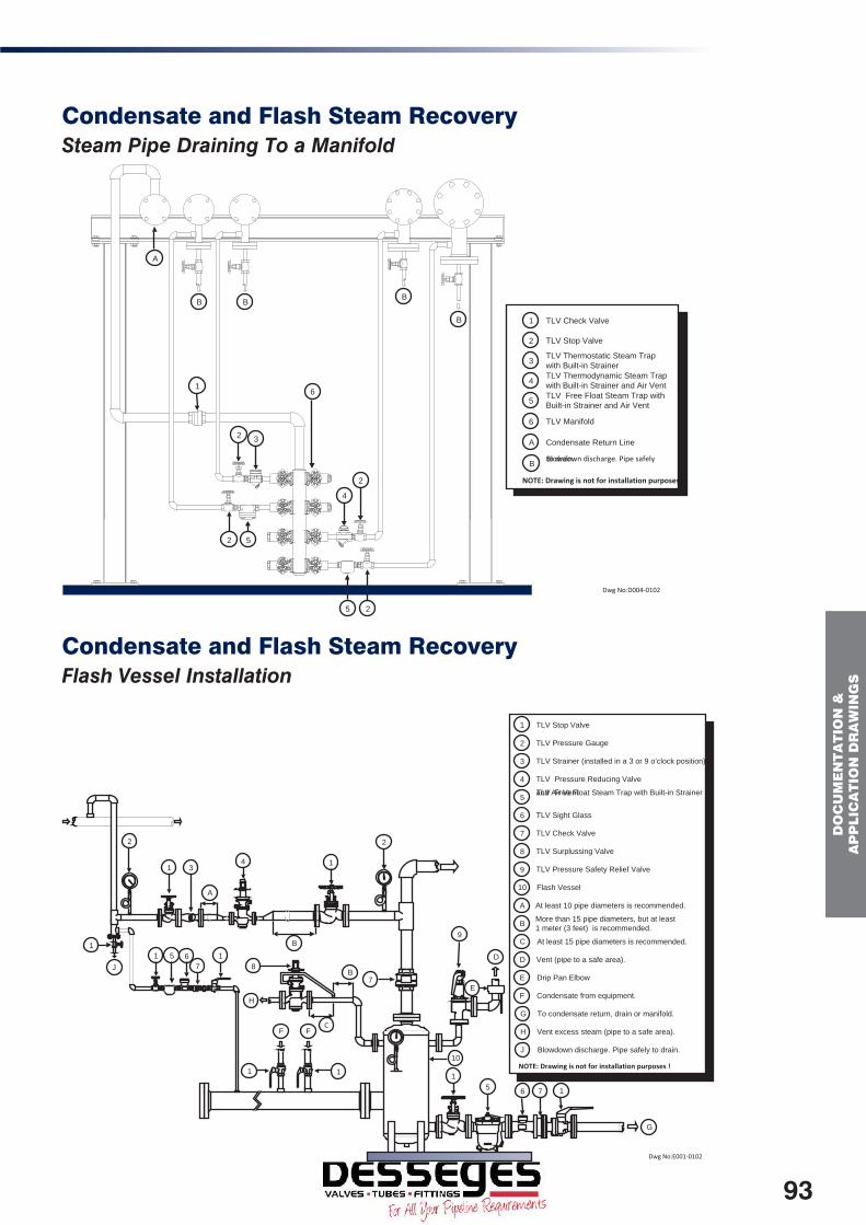
DO
CU
ME
NT
AT
ION
&
AP
PLIC
AT
ION
DR
AW
ING
S
Dwg No:D004-0102
TLV Check Valve
TLV Stop Valve
TLV Thermostatic Steam Trap
with Built-in Strainer
TLV Thermodynamic Steam Trap
with Built-in Strainer and Air Vent
TLV Free Float Steam Trap with
Built-in Strainer and Air Vent
1
2
3
4
5
TLV Manifold
6
A
NOTE: Drawing is not for installation purposes !
Blowdown discharge. Pipe safely to drain.B
Condensate Return Line
2 5
3
2
4
2
2
A
5
6
1
B B
B
B
Dwg No:E001-0102
TLV Stop Valve1
TLV Pressure Gauge
2
TLV Strainer (installed in a 3 or 9 o'clock position)
3
TLV Pressure Reducing Valve
4
TLV Free Float Steam Trap with Built-in Strainer and Air Vent
5
TLV Sight Glass
6
TLV Check Valve
7
TLV Surplussing Valve
8
TLV Pressure Safety Relief Valve
9
Flash Vessel10
At least 10 pipe diameters is recommended.A
B
More than 15 pipe diameters, but at least
1 meter (3 feet) is recommended.
CAt least 15 pipe diameters is recommended.
DVent (pipe to a safe area).
EDrip Pan Elbow
FCondensate from equipment.
GTo condensate return, drain or manifold.
HVent excess steam (pipe to a safe area).
JBlowdown discharge. Pipe safely to drain.
NOTE: Drawing is not for installation purposes !
C
1
2
4
3
1
2
1 5
6
7
A
B
D
1
5
6
7 1
1
8
F F
9
E
G
10
1
1
H
B
J
1
7
Condensate and Flash Steam RecoverySteam Pipe Draining To a Manifold
Condensate and Flash Steam RecoveryFlash Vessel Installation
93

D
OC
UM
EN
TA
TIO
N &
A
PP
LIC
AT
ION
DR
AW
ING
S
Dwg No:E003-0102
TLV Stop Valve
TLV Pressure Gauge
TLV Control Valve with I/P Converter and Positioner
TLV Controller
COSR Pressure Reducing Station (see separate drawing for details)
TLV Temperature Sensor
TLV Free Float Steam Trap with Built-in Strainer and Air VentFlash Vessel Installation (see separate drawing for details)
10
1
2
3
4
5
7
6
8
9
11
TLV Sight Glass
Blowdown discharge. Pipe safely to drain.
TLV Check Valve
Vent (pipe to a safe area).
To condensate return (at high level).
Slightly pitch to pump inlet.
General Condensate Recovery System with GP10 (see separate drawing for details)
A
B
C
D
NOTE: Drawing is not for installation purposes !
Overflow (pipe safely to drain).E
3
5
8
11
7
4
6
2
1
B
E
C
10
D
B
B
9
1
1
1
A
1
1
A
Condensate and Flash Steam RecoveryGeneral Condensate Recovery System using GP10 PowerTrap
1
2
3
4
5
6
7
NOTE: Drawing is not for installation purposes !
Condensate from equipment.
Slightly pitch to pump inlet.
Overflow (pipe safely to drain).
TLV Stop Valve
TLV Power Trap
TLV Strainer
TLV Check Valve
TLV Free Float Steam Trap with Built-in Strainer and Air Vent
TLV Sight Glass
TLV Pressure Gauge
A
B
C
Vent (pipe to a safe area).
D
Dwg No:E002-0102
1
1
2
7
1
4
5
6
4
4
D
A
1
C
2
1
1
B
B
1
3
Condensate and Flash Steam RecoveryExample of Flash Steam and Condensate Recovery from an Air Heater
94

DO
CU
ME
NT
AT
ION
&
AP
PLIC
AT
ION
DR
AW
ING
S
Condensate and Flash Steam RecoveryAir Handling Unit – Gravitational Drainage (Zero Back Pressure)
Dwg No:M001-0102
TLV Stop Valve
TLV Pressure Gauge
TLV Control Valve with I/P Converter and Positioner
TLV Controller
COSR Pressure Reducing Station (see separate drawing for details)
TLV Temperature Sensor
TLV Free Float Steam Trap with Built-in Strainer and Air Vent1
2
3
4
5
7
6
8
9
TLV Sight Glass
TLV Check Valve
Vent (pipe to a safe area).
To condensate return.
A
B
NOTE: Drawing is not for installation purposes !
5 4
6
21
3
1
2A
79
B
B
1 18
A
10
10 TLV Trap Set
Condensate and Flash Steam RecoveryAir Handling Unit – Pumped Drainage (For High Level Condensate Recovery)
Dwg No:M002-0102
5 4
6
21
3
1
2A
79
B
1 18
TLV Stop Valve
TLV Pressure Gauge
TLV Control Valve with I/P
Converter and Positioner
TLV Controller
COSR Pressure Reducing Station
(see separate drawing for details)
TLV Temperature Sensor
TLV Free Float Steam Trap with
Built-in Strainer and Air Vent
1
2
3
4
5
7
6
8
9
TLV Sight Glass
TLV Check Valve
Vent (pipe to a safe area).
To condensate return.
A
B
NOTE: Drawing is not for installation purposes !
B
A
A
TLV Trap Set
10
10
A
95

D
OC
UM
EN
TA
TIO
N &
A
PP
LIC
AT
ION
DR
AW
ING
S
Condensate and Flash Steam RecoveryCondensate Recovery from a Cylinder Dryer using a GP10 Power Trap
Dwg No:E004-0102
TLV Stop Valve
TLV Check Valve
TLV Sight Glass
TLV Free Float Steam Trap with Built-In
Strainer, Air Vent and Steam Lock Release Valve
General Condensate Recovery System with GP10
(see separate drawing for details).
1
2
3
4
5
Motive Steam Supply
Vent (pipe to a safe area).
To condensate return (at high level).
A
B
C
Slightly pitch to pump inlet.
D
Overflow (pipe safely to drain).
E
NOTE: Drawing is not for installation purposes !
12
A
1 1
3
4
5
1
2
3
4
B
C
E
D
Other Applications Boiling Pan (Fixed)
Dwg No:F002-0102
TLV Pressure GaugeTLV Stop Valve
TLV Pressure Reducing Valve with Built-in
Strainer, Separator and Free Float Steam Trap
TLV Pressure Safety Relief Valve
TLV Free Float Steam Trap with Built-in
Strainer and Air Vent
TLV Sight Glass
TLV Check Valve
TLV Air Vent with Built-in Strainer
At least 10 pipe diameters is recommended.
At least 15 pipe diameters is recommended.
A
1
2
3
4
5
7
6
8
B
To condensate return, drain or manifold.C
Vent (pipe to a safe area).D
Drip Pan ElbowE
NOTE: Drawing is not for installation purposes !
2 31
2
4
2 6
5
2
8
4
7
2
2
7
6
5
2
8
C
C
C
C
D
D
C
E
E
2
2
7
26
5
2
7
2
7
6
5
2
D
D
1
A
B
2
2
96

DO
CU
ME
NT
AT
ION
&
AP
PLIC
AT
ION
DR
AW
ING
S
Other Applications Laundry Conditioning Tunnel
Dwg No:F004-0102
TLV Pressure Gauge
TLV Stop Valve
TLV Pressure Reducing Valve with Built-in
Strainer, Separator and Free Float Steam Trap
TLV Pressure Reducing Valve
TLV Check Valve
TLV Air Vent with Built-in Strainer
TLV Sight Glass
1
2
3
4
5
7
6
TLV Free Float Steam Trap with Built-in
Strainer and Air Vent
8
At least 10 pipe diameters is recommended.
A
At least 15 pipe diameters is recommended.
B
Air Heater
C
Vent (pipe to a safe area).
D
To condensate return, drain or manifold.
E
NOTE: Drawing is not for installation purposes !
1
D
2
2
3
1
5
2
5
7
8
2
2
2
1
4
2
A
B
E
6
A B
C
2
Other Applications Multi-Roll Ironer
Dwg No:F005-0102
1
2
A
B
B
B
C
5 3
2 4
2
CB
6
3
2 4
2
22
5 3
2 4
25
3
24
2
TLV Air Vent with Built-in Strainer
TLV Stop Valve
TLV Check Valve
TLV Sight Glass
1
2
3
4
NOTE: Drawing is not for installation purposes !TLV Free Float Steam Trap with Built-in Strainer and Air Vent5
Vent (pipe to a safe area).
To condensate return, drain or manifold.
A
B
TLV Free Float Steam Trap with Built-in Strainer, Air
Vent and Steam Lock Release Valve
6
Blowdown discharge. Pipe safely to drain.
C
97

D
OC
UM
EN
TA
TIO
N &
A
PP
LIC
AT
ION
DR
AW
ING
S
Other Applications Platen Press
Dwg No:F006-0102
TLV Stop Valve
TLV Check Valve
TLV Sight Glass
TLV Free Float Steam Trap with Built-in Strainer and Air Vent
TLV Thermodynamic Steam Trap with Built-in Strainer and Air Vent
Vent (pipe to a safe area).
To condensate return, drain or manifold.
1
2
3
4
5
B
A
Blowdown discharge. Pipe safely to drain.C
NOTE: Drawing is not for installation purposes !
6
TLV Air Vent with Built-in Strainer
1
6
14 53
1
2
1
B
B
1
C
A
2
1
Other Applications Plating Tank
Dwg No:F007-0102
TLV Stop Valve
TLV Free Float Steam Trap with Built-in Strainer and Air Vent
TLV Sight Glass
TLV Check Valve
TLV Temperature Gauge
To condensate return, drain or manifold.
1
2
3
4
5
A
Lift FittingB
NOTE: Drawing is not for installation purposes !
1
1 2 3
4
1
A
5
B
98

DO
CU
ME
NT
AT
ION
&
AP
PLIC
AT
ION
DR
AW
ING
S
Other Applications Mill Roller and Cylinder Dryer
Dwg No:F008-0102
TLV Stop Valve
TLV Check Valve
TLV Sight Glass
TLV Free Float Steam Trap with Built-in Strainer and Air VentTLV Free Float Steam Trap with Built-in Strainer, Air Vent and Steam Lock Release Valve
1
2
3
4
5
NOTE: Drawing is not for installation purposes !
143
21
1
15
32 1
Other Applications Space Heater
F010-0102-SPACE HEATER.VSD
TLV Stop Valve
TLV Free Float Steam Trap with Built-in Strainer and Air
Vent
TLV Sight Glass
TLV Check Valve
1
2
3
4
NOTE: Drawing is not for installation purposes !
11
1
2 3
4
1
1
2 3
4
1
99

D
OC
UM
EN
TA
TIO
N &
A
PP
LIC
AT
ION
DR
AW
ING
S
Other Applications Sump Pit Waste Water Removal using a GP10L (Motive Medium: Air)
Dwg No:F011-0102
2
B
1
1
A
34
65
5
TLV Stop Valve
TLV Pressure Gauge
TLV Strainer
TLV Power Trap
TLV Check Valve
Vent (pipe to a safe area).
To condensate return, drain or manifold.
1
2
3
4
5
B
A
NOTE: Drawing is not for installation purposes !
Conical Strainer6
Other Applications Multi-Cylinder Dryer
Dwg No:F012-0102
TLV Air Vent with Built-in Strainer
TLV Stop Valve
TLV Check Valve
TLV Free Float Steam Trap with Built-in Strainer, Air
Vent and Steam Lock Release Valve
TLV Sight Glass
TLV Free Float Steam Trap With Built In Strainer And Air
Vent
General Condensate Recovery with GP10 (see separate
drawing for details).
1
2
3
4
5
7
6
Utilize or vent excess steam (pipe to a safe area).
Blowdown discharge. Pipe safely to drain.
Overflow (pipe safely to drain).C
A
B
To condensate return, drain or manifold.D
NOTE: Drawing is not for installation purposes !
1A
4
5
2
3
2
B
A
C
D
7
2
6
3 2
5
2
100

DO
CU
ME
NT
AT
ION
&
AP
PLIC
AT
ION
DR
AW
ING
S
Other Applications Laundry Tumble Dryer
Dwg No:F013-0102
TLV Pressure Gauge
TLV Stop Valve
TLV Pressure Reducing Valve with Built In Strainer, Separator and Free Float Steam Trap
TLV Pressure Safety Relief Valve
TLV Check Valve
TLV Strainer (installed in a 3 or 9 o'clock position)
TLV Sight Glass
TLV Free Float Steam Trap with Built-in Strainer and Air Vent
1
2
3
4
5
7
6
8
NOTE: Drawing is not for installation purposes !
At least 10 pipe diameters is recommended.A
At least 15 pipe diameters is recommended.B
Vent (pipe to a safe area).C
Drip Pan ElbowD
To condensate return, drain or manifold.E
E
E
25
7 2
6
2
2
2 57
1
D
1
4
2 23
2
C
E
A B
25
7 2
6
2
2
25
7
E
E
5
8 8
8
8
Other Applications Small Ironer
TLV Stop Valve
TLV Check Valve
TLV Sight Glass
TLV Free Float Steam Trap with Built-in Strainer, Air Vent and Steam Lock Release ValveTLV Thermodynamic Steam Trap with Built-in Strainer and Air Vent
1
2
3
4
5
NOTE: Drawing is not for installation purposes !
TLV Thermostatic Steam Trap with Built-in Strainer
The minimum distance should be 1 meter (3 feet).
6
A
Dwg No:F014-0102
1
5
3
2
1
1
A
1
1
6
3
2
1
1
1
4
3
2
1
101

D
OC
UM
EN
TA
TIO
N &
A
PP
LIC
AT
ION
DR
AW
ING
S
Other Applications Hospital Steriliser
F009-0102-STERILIZER.VSD
TLV Stop Valve
TLV Check Valve
TLV Sight Glass
TLV Free Float Steam Trap with Built-in Strainerand Air Vent
TLV Pressure Safety Relief Valve
1
2
3
4
5
TLV Air Vent with Built-in Strainer6
TLV Thermostatic Steam Trap with Built-in Strainer7
To condensate return, drain or manifold.
Vent (pipe to a safe area).
Drip Pan ElbowC
A
B
NOTE: Drawing is not for installation purposes !
5
14
3
2
1
A
B
C
B
1
7
21
6
A
1
Other Applications Optimum Critical Process Line Trace
Tracing Cross Section
D002-0102-CRITICAL PROCESS LINE TRACING.VSD
TLV Stop Valve
TLV Free Float Steam Trap with Built-in Strainer and Air Vent
TLV Sight Glass
TLV Check Valve
Insulation Flange Cuff
Insulation
To condensate return, drain or manifold.
1
2
3
4
A
C
B
NOTE: Drawing is not for installation purposes !
CC
C
C
1
1 2 3 1
4
A
B
41 2 3 1
1 2 3 1
1
41 2 3 1
C
C
1 2 3 1
1 2 3 1
4
4
4
102
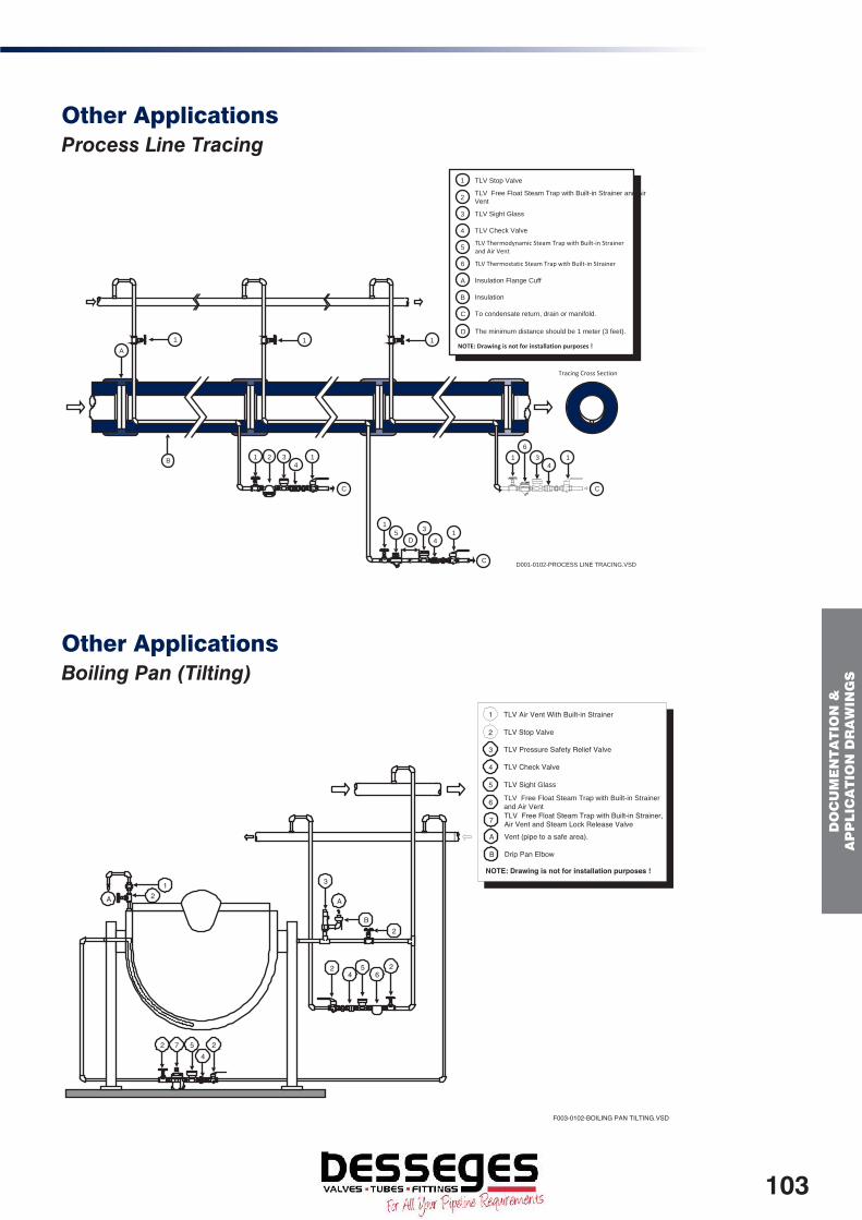
DO
CU
ME
NT
AT
ION
&
AP
PLIC
AT
ION
DR
AW
ING
S
Other Applications Process Line Tracing
Tracing Cross Section
D001-0102-PROCESS LINE TRACING.VSD
TLV Stop Valve
TLV Free Float Steam Trap with Built-in Strainer and Air
Vent
TLV Sight Glass
TLV Check Valve
Insulation Flange Cuff
Insulation
To condensate return, drain or manifold.
1
2
3
4
A
C
B
NOTE: Drawing is not for installation purposes !
TLV Thermodynamic Steam Trap with Built-in Strainer and Air Vent
TLV Thermostatic Steam Trap with Built-in Strainer
5
6
The minimum distance should be 1 meter (3 feet).
D
CC
C
1
4
1
6
3 1
A
B
4
1
5 1
4
1 2 3 1
1 1
D
3
Other Applications Boiling Pan (Tilting)
F003-0102-BOILING PAN TILTING.VSD
TLV Air Vent With Built-in Strainer
TLV Stop Valve
1
2
TLV Pressure Safety Relief Valve
TLV Check Valve
TLV Sig ht Glass
TLV Free Float Steam Trap with Built-in Strainer
and Air Vent
NOTE: Drawing is not for installation purposes !
3
4
5
6
TLV Free Float Steam Trap with Built-in Strainer,Air Vent and Steam Lock Release Valve7
Vent (pipe to a safe area).A
Drip Pan ElbowB
A
1
2
2564
2
22 7 54
A 2
3
B
103

FA
Qs
FAQsQuestions about TrapsIs it OK to insulate steam traps?The operating principle of some types of steam traps relies on fluctuations in temperature, so those types of traps must not be insulated. Mechanical types (float and bucket) may be insulated without any problem. Thermostatic types will not operate properly if insulated. For thermodynamic types, insulating measures should be limited to rain-proofing.
Is it OK to submerse trap outlets?Trap outlets should not be submerged as a general rule. If submerged, there is the danger that a vacuum will form inside the trap or at the trap inlet when the equipment is shut down, causing water to be sucked back up. This is not a problem if only water is sucked up, but if particulate matter such as dirt or sand is also sucked up, it can result in problems. If for some reason the outlet must be submerged, make a small air-intake hole in the piping to prevent the formation of a vacuum.
Is it OK to have a rise in the trap outlet piping?If the condensate is pressurised, this pressure (self-pressure) will allow the condensate to flow upward through rising piping. For example, the self-pressure of condensate at 1 barg will theoretically allow it to flow upward through a rise of approximately 10 m. However, and this is not limited to rises in piping, if the trap backpressure increases, the risk of the following must be considered:
• Reduced discharge capacity due to a decrease in trap operating differential pressure
• Tendency for failure of traps with low allowable backpressures (e.g. disc type)
In addition, as condensate will pool in vertical sections of piping during equipment shutdown, some arrangement for blowing out this condensate must be considered if such pooling is undesirable.
What is the safety factor for trap selection?The mechanism of operation for traps differs depending on the trap operation type. Some traps are extremely responsive, whereas others are extremely slow to respond. The recommended safety factors are determined based on the different operation types. Another parameter used in determining the various safety factors is the speed with which equipment start-up occurs. If rapid start-up times are required, a larger safety factor must be considered.
What is the possible trap operating pressure?Traps have a specified maximum operating pressure. They may not be used at pressures exceeding this value. Mechanical traps are broken down minutely into categories of maximum operating pressures. The maximum operating pressure is usually found in the numbers displayed at the end of each model of almost all TLV free float traps (units: bar). If this pressure is exceeded, the operation principle will cause the valve-closing force to become greater than the valve-opening force, and the trap will cease to operate (i.e. valve will no longer open).
Questions about Pressure Reducing Valves and Control ValvesIs a safety factor necessary in pressure reducing valve selection?There is no need to take into account a safety factor if selecting from within the designated flow rate.
Is it necessary to install a strainer in front of a pressure reducing valve?All TLV pilot-type reducing valves have an integral screen in the pilot section. In the COS series (with built-in separator and trap), there is an integral main valve screen. The COS-R series, however, does not have an integral main valve screen, so installation of a strainer with a minimum of a 60 mesh is recommended. In addition, in the COS series, if there is noticeable clogging of the integral screen due to dirt or scale, use the COS in conjunction with a strainer.
Questions about SparesDoes TLV supply Spare parts for their equipment?TLV offers a comprehensive range of replacement parts for their products. Should you need advice, please contact us.
Is there a Spare Parts guide?A product manual is supplied with all equipment. Within this document you can find exploded / cross sectional views with detailed descriptions of the Spare Parts available.
Details for routine maintenance and product specific trouble shooting can also be found within the manual.
Please contact TLV if you would like an electronic copy of these documents.
104

FA
Qs
General Questions about SteamWhy is a separator used?Separators are installed in steam or air piping and are used to separate out and remove moisture entrained in the steam or air. TLV’s DC-A and DC-S series features a cyclone style separator and free float trap combined into one unit.
What is the difference between an air vent for steam and an air vent for water?An air vent for steam is used to discharge air from a system in which both steam and air are found. An air vent for water is used to remove air from water piping systems. The air vent for steam employs thermostatic trap technology, which operates based on temperature differences. The air vent for water employs free float trap technology, which makes use of buoyancy. Thus, though they are both called ‘air vents,’ they cannot be used interchangeably; the air vent for steam must not be used on water systems, and vice versa.
What is ‘stall?’‘Stall’ occurs when a lack of trap operating differential pressure (the difference between the pressure in front of the trap and the pressure behind the trap) causes condensate to no longer be discharged from the trap and instead to pool inside the heat exchanger. It is sometimes due to the relationship between the load and heat transfer surface area of the equipment whose temperature is being controlled. A detailed explanation with animated drawings is available on our website
What is ‘steam locking?’‘Steam locking’ occurs when the flow of condensate into the trap is hindered by the steam pocket in front of the trap, and the discharge of condensate is delayed. Steam locking has a tendency to occur in equipment such as that with a rotating body and on which a siphon pipe is used (cylinder dryers, roll heaters). There are steam traps with an optional ‘lock release valve’ designed to eliminate such steam locking.
What are dampeners and siphon pipes used for?Dampeners are used to minimise the effects of pulsations or sudden surges on equipment such as pressure gauges. They restrict the pathway by means of a throttling mechanism similar to that of a needle valve. Siphon pipes are filled with fluid to prevent high temperature fluids from coming into direct contact with pressure gauges and transmitters, while at the same time preventing the radiant transmission of heat from the surface to the instrumentation.
Please note a detailed explanation with animated drawings can be found online at:
http://www.tlv.com/global/UK/steam-theory/
Questions about Condensate RecoveryAre check valves needed at trap outlets?Trap outlets are piped independently, and no check valve is required if the outlet is piped to atmosphere. For applications in which trap outlets are piped to a condensate return line, if some equipment may still be running while others are shutdown there is a chance that condensate will flow back up through the trap. A check valve must be installed to prevent this backflow.
What is two-phase flow design for condensate return lines?As the name implies, condensate return lines are pipelines through which condensate flows. Flash steam often accompanies hot condensate, however, and in this case flash steam (gas phase) and condensate (liquid phase) are found mixed together inside the piping. Two-phase flow piping design takes into account this mixture of gas and liquid. As the specific volume of steam is 100’s to over 1,000 times that of condensate, condensate return piping is more like steam piping than water piping. However, consideration must be given to flow rates that prevent the occurrence of condensate-induced (liquid phase) water hammer.
What is the motive medium for PowerTrap?Motive medium at a pressure higher than the backpressure is introduced into the body of the PowerTrap, and this pressure forces the discharge of condensate from the PowerTrap. The motive medium acts as the driving force, in the same manner as the piston in a child’s water pistol.
Is it ok to connect the outlets of traps with different pressures to the same return line?It depends on the conditions. Condensate will flash into flash steam when it travels from high pressure to low pressure. This results in a two-phase flow of flash steam and condensate inside the condensate return line. Such conditions require that this flash steam be taken into account when sizing the condensate return line (selecting proper pipe diameter). Careful consideration must be given if high pressure condensate is to be added to a return line designed to receive only low pressure condensate.
105
FA
Qs
Questions about Air and Drain TrapsWhat is the difference between air and drain traps?Air traps are used to remove condensate from the ends of air piping, from receiver tanks, etc. Some models have larger orifices to facilitate the removal of high viscosity condensate with entrained oil or scale. As corrosion resistance is not of particular importance, trap bodies are typically constructed of cast iron.
Drain traps, as defined by TLV, are traps which are available in two forms - for air or non-flammable, non-toxic gas applications. Drain traps are used to remove condensate from air or non-flammable, non-toxic gas systems requiring a tight seal. For this reason, TLV drain traps employ 3-point seating to provide a tight seal even under low condensate load conditions. Products constructed of materials suitable for use on high pressure lines are also available.
What is the difference between metal valve seats and rubber valve seats?The most important feature of rubber valve seats in comparison with metal valve seats is their superior sealing ability under low condensate load conditions. Rubber valve seats are therefore ideal for applications in which a trap is necessary but the amount of condensate is extremely small. However, even under the same maximum operating pressure rubber valve seats also feature small discharge capacities, low maximum operating temperatures and a limited number of fluids with which they can be used.
I’m using an air trap, but why is condensate not being removed as expected?Is the trap designed for use with a pressure-balancing line? If the displacement of the air inside the trap by the inflowing condensate is not taking place as it should, condensate can no longer flow into the trap and the discharge of condensate from the trap will cease completely. A pressure-balancing line will prevent this from occurring. The air inside the trap is released through the pressure-balancing line when condensate flows into the trap, allowing the condensate to be discharged smoothly.
General Questions about Air SystemsWhy does water drip from air equipment during hot, humid weather?In humid weather incoming air contains a higher water content and this is seen being discharged. If the condensate that forms inside the piping is not removed properly, the operation of air-using equipment such as receiver tanks, after-coolers and piping may be hindered. In particular, during periods of high humidity and high temperatures condensate flow rates increase, this can lead to these types of problems.
Is there a valve for use on air applications?TLV ball butterfly valves are a soft-seat type, employing a Fluorine Resin (PTFE) valve seat, making them suitable for use on air applications. These products are not listed in our promotional materials or website so please contact us directly for further information. The standard bellows-sealed valve series are of a metal-seat type with a metal valve seat and valve body, which from the standpoint of sealing ability are not particularly suited for use on air applications.
General Questions about InformationAre there Operating Manuals for TLV equipment? And how can I get them?All TLV products are shipped with the relevant Operation and Maintenance Manuals. These offer a detailed explanation of the product along with exploded views for better understanding of the products. Spare parts list and maintenance guidelines are also included. If you need an additional copy, please feel free to contact TLV to request these. Most are also available to download on our website.
Is there any more information for the products included within this price list?A range of literature is available online at www.TLV.com should the information you seek cannot be found there, please feel free to contact us by phone or email.
106

TA
BLE
S &
DA
TA
Tables and Data
Steam Table
Gauge PressureSaturated
TemperatureSpecific enthalpy
Water Evaporation Steam
(P) (t) (hf) (hfg) (hg)barg kPa °C kJ/kg kJ/kg kJ/kg
0.0 0 100.0 419 2257 26760.1 10 102.7 430 2250 26800.2 20 105.1 441 2243 26840.3 30 107.4 450 2237 26880.4 40 109.6 460 2231 26910.5 50 111.6 468 2226 2694
0.6 60 113.6 476 2220 26970.7 70 115.4 484 2215 27000.8 80 117.1 492 2211 27020.9 90 118.8 499 2206 27051.0 100 120.4 506 2201 2707
1.5 150 127.6 536 2181 27172.0 200 133.7 562 2163 27262.5 250 138.9 584 2147 27313.0 300 143.8 605 2133 27393.5 350 147.9 623 2120 27434.0 400 152.0 641 2108 27494.5 450 155.6 656 2097 27535.0 500 158.9 671 2086 2757
5.5 550 162.1 685 2076 27606.0 600 165.0 698 2066 27646.5 650 167.8 710 2057 27677.0 700 170.5 721 2048 27697.5 750 173.0 733 2039 27728.0 800 175.4 743 2031 27748.5 850 177.8 753 2023 27769.0 900 180.0 763 2015 27789.5 950 182.1 773 2008 278010.0 1000 184.1 782 2000 2782
11.0 1100 188.0 799 1986 278512.0 1200 191.7 815 1973 278813.0 1300 195.1 830 1960 279014.0 1400 198.4 845 1947 279215.0 1500 201.5 859 1935 279416.0 1600 204.4 872 1923 279617.0 1700 207.2 885 1912 279718.0 1800 209.9 897 1901 279919.0 1900 212.5 909 1891 280020.0 2000 215.0 920 1880 2801
21.0 2100 217.4 931 1870 280122.0 2200 219.7 942 1860 280223.0 2300 221.9 952 1850 280324.0 2400 224.0 962 1841 280325.0 2500 226.1 972 1831 2804
107

T
AB
LE
S &
DA
TA
Steam Capacity (kg/h) in a pipe based on VelocitiesPressure
bargVelocity
(m/s)Pipe Size (mm)
15 20 25 32 40 50 65 80 100 125 150 200 250
0.5 10 7 12 19 33 45 72 120 166 279 423 619 1048 165415 10 18 29 50 67 108 180 249 419 634 928 1572 248120 14 24 39 67 90 144 241 332 559 846 1238 2096 330830 21 36 59 101 135 217 361 498 839 1269 1857 3145 4963
1 10 9 15 25 44 59 94 157 217 366 553 810 1372 216515 14 23 38 66 88 142 236 325 549 830 1215 2058 324720 19 31 51 88 118 189 315 434 732 1107 1620 2744 433030 28 47 77 132 177 284 473 651 1098 1661 2430 4116 6495
2 10 13 23 37 64 86 138 230 317 535 809 1184 2006 316515 20 34 56 96 130 208 346 476 803 1214 1777 3009 474820 27 46 75 129 173 277 461 635 1071 1619 2369 4012 633130 41 69 113 193 260 416 692 953 1606 2429 3554 6018 9497
3 10 18 30 49 84 113 181 302 416 701 1060 1552 2628 414715 27 45 74 126 170 272 453 624 1052 1591 2328 3942 622120 36 60 99 169 227 363 604 832 1403 2121 3104 5257 829530 54 91 149 253 340 545 906 1248 2104 3182 4656 7885 12443
4 10 22 37 61 104 140 224 372 513 865 1308 1914 3242 511615 33 56 91 156 210 336 559 770 1298 1962 2871 4863 767420 45 75 122 208 280 448 745 1027 1730 2617 3829 6484 1023230 67 112 183 313 420 672 1118 1540 2596 3925 5743 9726 15348
5 10 26 44 72 123 166 266 442 609 1027 1554 2273 3850 607515 40 66 109 185 249 399 664 914 1541 2331 3410 5775 911320 53 89 145 247 332 532 885 1219 2055 3108 4547 7700 1215130 80 133 218 371 499 798 1328 1829 3083 4662 6821 11551 18226
6 10 31 51 84 143 192 307 512 705 1189 1797 2630 4454 702815 46 77 126 215 288 461 768 1058 1783 2696 3945 6681 1054320 62 103 168 286 385 615 1024 1411 2378 3595 5260 8909 1405730 93 154 252 430 577 923 1536 2116 3567 5393 7891 13363 21086
7 10 35 58 95 162 218 349 581 800 1349 2041 2986 5057 797915 52 87 143 244 327 524 872 1201 2024 3061 4479 7585 1196920 70 117 191 325 437 699 1163 1601 2699 4082 5972 10114 1595930 105 175 286 488 655 1048 1774 2402 4049 6123 8958 15171 23938
8 10 39 65 106 182 244 390 650 895 1509 2282 3339 5654 892215 59 98 160 273 366 586 975 1343 2264 3423 5008 8482 1338320 78 130 213 364 488 781 1300 1791 3018 4564 6678 11309 1784530 118 196 320 546 733 1172 1950 2686 4528 6847 10017 16964 26767
9 10 43 72 118 201 270 432 718 990 1668 2523 3691 6251 986315 65 108 177 301 405 648 1078 1485 2502 3784 5537 9376 1479520 87 144 236 402 540 864 1437 1980 3337 5046 7382 12502 1972730 130 217 354 603 810 1296 2156 2970 5005 7569 11074 18753 29590
10 10 47 79 129 220 296 473 787 1084 1828 2764 4045 6850 1080815 71 118 194 330 444 710 1181 1627 2742 4147 6067 10275 1621320 95 158 258 441 592 946 1575 2169 3656 5529 8090 13700 2161730 143 237 388 661 888 1420 2363 3254 5485 8294 12135 20550 32426
14 10 64 106 174 297 398 637 1061 1461 2462 3724 5448 9227 1455915 96 160 261 445 598 956 1591 2192 3694 5586 8173 13840 2183920 128 213 348 594 797 1275 2122 2922 4925 7448 10897 18454 2911830 192 320 523 891 1196 1913 3183 4384 7388 11172 16346 27681 43678
16 10 72 120 196 335 450 719 1197 1649 2779 4202 6149 10413 1643015 108 180 295 502 675 1079 1796 2473 4169 6304 9223 15619 2464620 145 241 393 670 900 1439 2395 3298 5558 8405 12298 20826 3286130 217 361 590 1005 1350 2159 3592 4947 8338 12608 18447 31239 49292
21 10 93 155 253 431 579 926 1540 2122 3576 5408 7912 13399 2114315 139 232 379 647 868 1389 2311 3183 5364 8112 11868 20099 3171420 186 310 506 862 1158 1852 3081 4244 7153 10816 15825 26798 4228630 279 465 759 1294 1737 2778 4622 6366 10729 16224 23737 40198 63429
Based on DIN 2448 Reihe 1
108

Index
AA3N 60A-DR20 25Air Traps 43, 44, 45Air Vents 39, 40, 41, 42
BBD2 14BE3L 7BE8H 7BOA-H 7BV1 6BV6 6BV4290 6BV4290-ACT 33BV4291-ACT 33BV5111 6BZ 15
CCertificates 83Check Valves 9CK3M 9CK3T 9CKF3M 9COS-3 22COS-16 22COS-21 22COSR-3 24, 25COSR-16 24COSR-21 24CV5 32CV-COS 32
DDBB 8DBB-16 8DBB-25 8DBB-40 8DC3A 15DC3S 15DC7 15Documentation 83DR 27DR8-EP 26DR8-P 26DR20 25
EEF200 19
FF46 68Fig 500 29Filters 17
GGL14M Packaged Pump System 72GLP10L Packaged Pump System 72GP5C 71GP10F 71GP10F Packaged Pump System 72GP10L 71GP14 71GP14L 71GP14L Packaged Pump System 72GP14M 71GP21F 71GT5C 70GT10/GT14 70GT10L 70GT10M/GT14M 70
HHeatPacks 73HR80A 61HR150A 61HR260A 61
JJ3SX 50J3X 50J5SX 50J5X 50J6SX 50J7.2X 50J7.5X 50J7X 50, 51J8X 50J10 58JA3 44JA3D 44JF3SX 50JF3X 50JF5X 50JH3SB 52JH3SX 52JH5RHB 52JH5RLB 52JH5RLX 52JH5SHB 52JH5SLB 52JH5SLX 52JH7.2RX/B 54JH7.5RX/B 54JH7RHB 53JH7RHP 53JH7RHW 53JH7RLB 53JH7RLX 53JH7RMB 53JH8RX/B 54JH15E 54JH15M 54JH15S 54JL9X 58JL14X 58JLH9X 58JLH14B 58
LL21S 64L21SE 64L32 67L32S 64L32SE 64LA13L 42LA21 42LEX3N-TZ 65LH14X 58LV6 66LV13L 64LV13N 64LV21 64
MM1 37M4 37Manifolds 77
NNF6 14
PP46S 60P46SRM 60P46SRN 60P46SRW 60P46UC 67P46UC-Y 67P65SRN 60P-EGS Series 17PN-COS 32Pressure Reducing Valves 21Pressure Transmitter 27PT1 79PT100 27
SSA3 41Safety Valves 29SCOS-16 22SCOSR-16 24Separators (Cyclone Type) 15Series 451 29Series 645 29Series 851 29SF1 17SF-320 12SG18 13SG18E 13SH3NL 56SH5NH 56SH5NL 56SH6NH 57SH6NL 57SH7NH 57SH7NL 57Sight Glasses 11, 12, 13, 14SJ3FX 51SJ3VX 51
109

TLV Guarantee
Customer SatisfactionTLV is true to the philosophy of complete customer satisfaction through strict adherence to its two fundamental policies:
• Quality First
• Incomparable Originality
Only through providing superior products and services that are of great benefit to the customer can complete satisfaction be guaranteed. This is the credo that has supported TLV's growth since its inception, and will continue to be the guide into the future.
Quality First
TLV's quality system is certified to ISO9001, with products and services exceeding the strictest standards and requirements for a wide range of applications including nuclear power generation and pharmaceutical grade clean steam.
Incomparable Originality
TLV approaches product development with continuous dedication to customer needs. Development means the creation of totally new ideas and concepts. The many patents derived through this development process attest to TLV's dedication to innovation.
SJ5FX 51SJ6FX 51SJ7FX 51SJH3X 51SJH5X 51SJH7X 51SP-COSR-16 36SR 20.40 9SS1 55SS1VG 44SS3 55SS3 Bio 55SS3P 66SS5 55SS5P 66Steam Compressor 75Strainers 11, 12, 13, 14SV441 29
TT5N 13T8N 13TATSU 45TC1 35TC1-S 35TC2 35TF8N 13Type 2100 33
VV1 68V2 68V2001-E1 34V2001-E3 34VA 40Vacuumiser 74
VAS 40VC 41VC3 41VC4 41VK70 42Vortex Flowmeters 19VS1C 41VS3P 66
XX5 37
YY3 12Y8F 12
110

Useful InformationConnection StandardsTLV offers products in a variety of connection standards for flexibility to customers. As standard, screwed connections comply with British Pipe Standards (BSP) and flanged connections to DIN 2501 (PN16, 25 and 40) and ASME Class (125, 150, 300, 600 and 900) unless otherwise stated.
Other options include:Screwed – BSP, NPTSocket Weld – ASME B16.11 Butt Weld – DIN 3239 Form CFlanges – DIN 2501 (PN16, 25 & 40), ANSI (Class 150, 300, 600, 900)Tube end - 8, 10, 15mm OD (suitable for Lockring couplings) (F32)Tri-clamp† connections – 2 piece and 3 piece to ISO, DIN and BS standards† Trademark of Tri-Clover Inc.
ContactTLV Euro Engineering UK Ltd.Star Lodge,Montpellier Drive,Cheltenham,Gloucestershire. GL50 1TYTelephone: +44(0)1242 227 223Fax: +44(0)1242 223 077
Please contact our Technical Team ([email protected]) if you require any technical advice about any TLV products, future projects or current installations. TLV Sales team ([email protected]) can offer support for purchasing, invoicing and delivery information.
TLV also offers site visits from one of our Regional Sales Engineer.