Embed Size (px)
Citation preview

Price list 2014International
Valid from 01/01/2014

Reflex has set itself the goal of supporting you with well thought-out solutions. Whatever job you need doing in water supply engineering, why not put your trust in our compre-hensive range of products and accompanying tailored services? We will ensure that your decision to opt for Reflex is the right one in every respect – from advice and design to installation and ongoing operation.
Reflex's mission is embodied in the company's slogan: "Thinking solutions". Reflex's strength is to think in terms of solutions. Reflex develops ideas that help you to move forward based on decades of experience, in-depth technical understanding and intimate knowledge of the industry!
We are only satisfied if you are.
2

33
We are only satisfied if you are.
We make sure that everything fits
Heating, cooling and hot water supply systems – the de-mands on supply equipment are varied and complex. You'll be well-advised for every eventuality with our coordinated product ranges. Reflex can offer you the right components for each specific task – and you can be sure that they can be integrated seamlessly into the interplay of a larger overall solution. The result: well thought-out systems that simply perform better.
In this price list, we've summarised our entire product range for you (as at 12/2013), meaning you can locate all our available products, series and technical information quickly and easily. Please note that all quotes are inclusive of recommended retail prices in euros plus VAT. All weights given are net weights. Reflex reserve the right to modify the details published in this document and our General Terms and Conditions of Business and Delivery apply as of the 01/01/2013 version.
Contents
Diaphragm Expansion VesselsDiaphragm expansion vessels for heating, solar power and cooling water systemsReflex N and NG 7Reflex F 8Reflex C 8Reflex G 9Reflex S 10Intermediate vessels 11Accessories for Reflex 12–13
Diaphragm expansion vessels for potable water systems, pressure booster systems and hot water systems
Refix DD 15 Refix DT 17–18 Refix DE 20–21 Refix DC 24Refix HW 26
Pressurisation SystemsCompressor-controlled systems Reflexomat (incl. accessories) 29–34 Pump-controlled systems Variomat (incl. accessories) 35-40 Variomat Giga (incl. accessories) 41-44
Water Make-Up Systems & Water TreatmentFillset 47Fillcontrol 48-49Fillsoft 50
Deaeration Systems & Separation TechnologyServitec 52-54Exvoid 55-57Exdirt 58-60Extwin 61-62Accessories, dirt collectors 63Air separators 64Expansion traps 64
Hot Water Storage Tanks & Heat ExchangersStoratherm Heat buffer storage tank 66-68Storatherm Heat storage combined storage tank 69Accessories for storage tank 69-71Storatherm Aqua 72–76Accessories for Storatherm Aqua 77–81 Longtherm 82-85Accessories for Longtherm 86-87
ServicesYour field sales contact 92-93General Terms and Conditions of Business and Delivery 94
DiaphragmExpansionVessels
PressurisationSystems
Water Make-UpSystems &Water Treatment
Hot Water Storage Tanks & Heat Exchangers
Services
Deaeration Systems & SeparationTechnology
The Reflex
Product Range

Product highlights 2014Reflex ControlThe latest evolution in the operation and control of make-up stations, pressurisation systems and deaeration systems. It received the renowned Plus X Award for operating convenience and functionality.
• Simple operation• Wide range of interfaces• Maximum versatility in the system networking• Plain text display (Control Touch)• Process visualisation (Control Touch)• Integrated service and operation menu (Control Touch)
Further information can be found on page 28 and with the following Reflex products:
Reflex ExferroFor reliable protection of sensitive highly efficient pumps
• Efficient separation of ferromagnetic substances in the main flow
• Available in dirt separators of the Exdirt series and in combined air and dirt separators of the Extwin series
Further information on pages 59, 61 and 63
Reflex Storatherm Heat CombiLatest generation freshwater tank
• Storage tank with corrugated stainless steel pipe in four sizes: 500 l, 800 l, 1000 l and 1500 l
• 120 mm non-woven thermal insulation• Available with one or two heat exchangers for efficient
integration of several heat sources
Further information on page 69
Fillcontrol Plus(from page 48)
Fillcontrol Auto Compact(from page 49)
Servitec(from page 52)
Reflexomat(from page 29)
Variomat(from page 35)
4

Diap
hrag
m E
xpan
sion
Ves
sels
Diaphragm Expansion Vessels

Definitions in accordance with DIN EN 12828 and following DIN 4807 T1/T2 based on the example of a heating system with a diaphragm expansion vessel.
pSV Safety valve activation pressure
pf Final pressure
pfil Filling pressure
pi Initial pressure
pst Static pressure
p0 Minimum operating temperature = Input pressure for expansion vessel = PLmin Minimum pressure limiter
= PLmax pressure relief valve 0.2
bar
Clos
ing
pres
sure
di
ffere
nce
acc.
to T
RD 7
21 =
ASV
Ve E
xpan
sion
vol
ume
Setp
oint
val
ue ra
nge
for
pres
sure
mai
nten
ance
=
norm
al p
ress
ure
leve
l
V WS W
ater
se
al
≥ 0.
3 ba
r≥
0.2
bar
+ pe
The permissible excess operating pressure must not be exceeded at any point within the system.
Pressure in the system at maximum temperature
Pressure in the system at filling tem-peraturePressure in the system at minimum temperature
Minimum pressure to prevent - Vacuum formation - Evaporation - Cavitation
Pressure of liquid column based on static height (H)
Normal pressure range = Pressure maintenance
setpoint value
between pi and pf
Water seal VWS to cover system-related water losses
PLmin acc. to DIN EN 12828; to ensure p0 in hot water systems, an automatic water make-up system is recommended, along with an optional minimum pressure limiter.
PLmax required in accord-ance with DIN EN 12828 if individual boiler output> 300 kW
PAZ+
PAZ
ReflexDiaphragm Expansion Vessels
Most common configuration = Suction pressure maintenance• Circulating pump in advance• Expansion vessel in return
Diap
hrag
m E
xpan
sion
Ves
sels
tV
pSV
pf
p0
pst, H
pfil, pi
tR
PAZ+
PAZ
6

7
Diaphragm Expansion Vessels
Reflex N and NG
• For closed heating and cooling systems • With threaded connections• From 35 litres upright• Diaphragm in accordance with DIN EN 13831, perm. operat-
ing temperature 70 °C• For up to 50 % addition of anti-freeze • Approved in accordance with Pressure Equipment Directive
97/23/EC
Type3 bar/120 °C
Article no. Grey White
Unit price€
Material group
PU Weightkg
Ø Dmm
Hmm
hmm
A Pre-set pressure bar
N 8 8202500 7202800 37.80 12 96 1.9 206 286 – R ¾ 1.5N 12 8203300 7203500 39.20 12 60 2.2 272 313 – R ¾ 1.5N 18 8204300 7204400 42.10 12 60 2.9 308 361 – R ¾ 1.5N 25 8206300 7206400 50.40 12 48 3.6 308 481 – R ¾ 1.5N 35 8208400 7208500 64.40 12 24 5.0 376 465 130 R ¾ 1.5
Type6 bar/120 °C
Article no. Grey White
Unit price€
Material group
PU Weightkg
Ø Dmm
Hmm
hmm
A Pre-set pressure bar
N 50 8001011 7001100 81.10 11 24 5.7 409 493 175 R ¾ 1.5N 80 8001211 7001300 120.00 11 12 8.7 480 565 175 R 1 1.5N 100 8001411 7001500 226.00 11 10 11.4 480 670 175 R 1 1.5N 140 8001611 7001700 265.00 11 8 13.1 480 912 175 R 1 1.5
3 ba
r6
bar
Diap
hrag
m E
xpan
sion
Ves
sels
Ø D
8 – 25 litresA
H
300–1000 litres
Ø D
H
h
Ø D
35 – 250 litres
H
h
Vn Nominal volume/litres
Vn Nominal volume/litres
Vn Nominal volume/litres
Type6 bar/120 °C
Article no. Grey White
Unit price€
Material group
PU Weightkg
Ø Dmm
Hmm
hmm
A Pre-set pressure bar
NG 8 8230100 7230107 37.80 10 96 1.6 206 285 – R ¾ 1.5NG 12 8240100 7240107 39.20 10 72 2.4 280 275 – R ¾ 1.5NG 18 8250100 7250107 42.10 10 56 3.4 280 345 – R ¾ 1.5NG 25 8260100 7260107 50.40 10 42 4.2 280 465 – R ¾ 1.5NG 35 8270100 7270107 64.40 10 24 4.8 354 460 130 R ¾ 1.5NG 50 8001011 7001100 81.10 11 24 5.7 409 493 175 R ¾ 1.5NG 80 8001211 7001300 120.00 11 12 8.7 480 565 175 R 1 1.5NG 100 8001411 7001500 226.00 11 10 11.4 480 670 175 R 1 1.5NG 140 8001611 7001700 265.00 11 8 13.1 480 912 175 R 1 1.5
N 50 8209300 7209400 59.15 13 24 9.6 441 496 175 R ¾ 1.5N 80 8210200 7210600 87.90 13 12 13.3 512 566 175 R 1 1.5N 100 8216300 – 165.50 13 10 15.8 512 673 175 R 1 1.5N 140 8211400 – 193.00 13 6 19.9 512 892 175 R 1 1.5
N 200 8213300 – 319.00 18 4 22.0 634 758 205 R 1 1.5N 250 8214300 – 457.00 18 4 24.7 634 888 205 R 1 1.5N 300 8215300 – 535.00 18 – 27.0 634 1092 235 R 1 1.5N 400 8218000 – 659.00 18 – 47.0 740 1102 245 R 1 1.5N 500 8218300 – 879.00 18 – 52.0 740 1321 245 R 1 1.5N 600 8218400 – 1,338.00 18 – 66.0 740 1531 245 R 1 1.5N 800 8218500 – 1,660.00 18 – 96.0 740 1996 245 R 1 1.5N 1000 8218600 – 2,123.00 18 – 118.0 740 2406 245 R 1 1.5
6 ba
r

Diaphragm Expansion Vessels
Diap
hrag
m E
xpan
sion
Ves
sels
Vn Nominal volume/litres
Reflex F
• Flat vessel for heating and cooling water systems, especially suited for installation within the boiler
• For up to 50 % addition of anti-freeze • Diaphragm in accordance with DIN EN 13831,
perm. operating temperature 70 °C• From 18 litres, supplied with suspension bracket• Approval in accordance with the Pressure Equipment Directive
97/23/EC
Type3 bar/120 °C
Article no.White
Unit price€
Material group
PU Weightkg
Hmm
W mm
D mm
A Pre-set pressure bar
F 8 9600011 64.40 15 54 6.3 389 389 88 G 0.75F 12 9600030 75.70 15 36 7.7 444 350 108 G ½ 1.0F 15 9600040 79.90 15 36 8.2 444 350 134 G ¾ 1.0F 18 9600000 83.90 15 28 8.7 444 350 158 G ¾ 1.0F 24 9600010 107.00 15 25 9.4 444 350 180 G ¾ 1.0
8 litres 12–24 litres
W WD D
H HH H
A A
3 ba
r3
bar
Vn Nominal volume/litres
Reflex C
• For heating and cooling water systems • For up to 50 % addition of anti-freeze • Incl. suspension bracket for ease of installation • Butyl diaphragm in accordance with DIN EN 13831, perm.
operating temperature 70 °C• Approval in accordance with the Pressure Equipment
Directive 97/23/EC
Type3 bar/120 °C
Article no.Grey
Unit price€
Material group
PU Weightkg
Ø Dmm
Hmm
D mm
W mm
A Pre-set pressure bar
C 8 8280000 49.50 17 96 2.8 280 287 163 52 G ½ 1.0C 12 8280100 51.90 17 60 3.2 354 362 168 64 G ½ 1.0C 18 8280200 56.70 17 42 4.7 354 362 222 76 G ¾ 1.0C 25 8280300 64.80 17 42 5.5 409 419 239 93 G ¾ 1.0C 35 8280400 75.50 17 24 7.3 480 457 240 97 G ¾ 1.0C 50 8280500 100.00 17 20 8.1 480 457 318 125 G ¾ 1.5C 80 8280600 141.00 17 8 14.5 634 612 325 135 G ¾ 1.5
Ø D
A
H
D
W
8

9
10 b
arDiaphragm Expansion Vessels
Reflex G
• For heating and cooling water systems • Up to 1000 l/Ø 740 mm, with threaded connections• From 1000 l/Ø 1000 mm with flanged connections DN 65• Diaphragm in accordance with DIN EN 13831, perm. operating
temperature 70 °C• Approval in accordance with the Pressure Equipment Directive
97/23/EC• With inspection port• Incl. pressure gauge• Pressure gauge and pre-set pressure valve protected by metal
brackets• Diaphragm can be replaced
Non-standard models on request
• Individual approval carried out by the TÜV [Technical Inspection Association], in accordance with the Pressure Equipment Directive 97/23/EC
• From 1000 litres/Ø 1000 mm with MBM coupling• Special vessel > 10 bar
Type6 bar/120 °C
Article no.Grey
Unit price€
Material group
Weightkg
Ø Dmm
Hmm
hmm
A Pre-set pressure bar
G 400 8521605 1,084.00 21 43.0 740 1253 146 G 1 3.5G 500 8521705 1,266.00 21 51.0 740 1473 146 G 1 3.5G 600 8522605 1,402.00 21 66.0 740 1718 146 G 1 3.5G 800 8523610 1,719.00 21 94.0 740 2183 146 G 1 3.5
G 1000 Ø 740 8546605 2,210.00 21 150.0 740 2593 146 G 1 3.5
G 1000 Ø 1000 8524605 3,466.00 22 228.0 1000 1973 307 DN 65/PN 6 3.5G 1500 8526605 4,197.00 22 280.0 1200 1971 305 DN 65/PN 6 3.5G 2000 8527605 6,797.00 22 250.0 1200 2431 305 DN 65/PN 6 3.5G 3000 8544605 9,396.00 22 620.0 1500 2480 334 DN 65/PN 6 3.5G 4000 8529605 10,526.00 22 770.0 1500 3053 334 DN 65/PN 6 3.5G 5000 8530605 11,656.00 22 849.0 1500 3588 334 DN 65/PN 6 3.5
Type10 bar/120 °C
Article no.Grey
Unit price€
Material group
Weightkg
Ø Dmm
Hmm
hmm
A Pre-set pressure bar
G 100 8518000 657.00 21 14.9 480 856 153 G 1 3.5G 200 8518100 923.00 21 33.4 634 972 144 G 1 ¼ 3.5G 300 8518200 1,227.00 21 34.6 634 1273 144 G 1 ¼ 3.5G 400 8521005 1,757.00 21 51.0 740 1245 133 G 1 ¼ 3.5G 500 8521006 2,056.00 21 57.1 740 1475 133 G 1 ¼ 3.5G 600 8522006 2,620.00 21 118.0 740 1859 263 G 1 ½ 3.5G 800 8523005 2,980.00 21 166.0 740 2324 263 G 1 ½ 3.5
G 1000 Ø 740 8546005 3,407.00 21 174.0 740 2604 263 G 1 ½ 3.5
G 1000 Ø 1000 8524005 4,056.00 22 335.0 1000 2001 286 DN 65/PN 16 3.5G 1500 8526005 4,959.00 22 390.0 1200 1991 291 DN 65/PN 16 3.5G 2000 8527005 7,689.00 22 485.0 1200 2451 291 DN 65/PN 16 3.5G 3000 8544005 11,371.00 22 830.0 1500 2532 320 DN 65/PN 16 3.5G 4000 8529005 12,261.00 22 1064.0 1500 3107 320 DN 65/PN 16 3.5G 5000 8530005 13,153.00 22 1274.0 1500 3642 320 DN 65/PN 16 3.5
Vn Nominal volume/litres
Ø D
HH
h
600 – 1000 litresØ 740
1000 – 5000 litresØ 1000
100 – 500 litres
Ø D
h h
Ø D
H
6 ba
r
Diap
hrag
m E
xpan
sion
Ves
sels

Diaphragm Expansion Vessels
Diap
hrag
m E
xpan
sion
Ves
sels
10 b
ar
Reflex S
• For solar, heating and cooling water systems • For up to 50 % addition of anti-freeze • With threaded connections• Diaphragm in accordance with DIN EN 13831, perm.
operating temperature 70 °C• Approval in accordance with the Pressure Equipment
Directive 97/23/EC• 33 litres with suspension brackets, from 50 litres with feet
Notes for the installer
• Because of the low temperature load, the circulating pump and Reflex S are located in the collector return. This means that the expansion vessel must be installed on the pressure side of the circulating pump. The circulating pump pressure must therefore be considered when calculating the pre-set pressure p0.
• There is no need to install the Reflex 'V in-line vessel' where the maximum possible temperature load for the expansion vessel is 70 °C.
Type10 bar/120 °C
Article no. Grey White
Unit price€
Material group
PU Weightkg
Ø Dmm
Hmm
hmm
A Pre-set pressure
barS 2 8707700 – 31.30 14 280 1.0 132 260 – G ¾ 0.5S 8 8703900 9702600 57.40 14 96 2.5 206 316 – G ¾ 1.5S 12 8704000 9702700 61.70 14 72 2.5 280 300 – G ¾ 1.5S 18 8704100 9702800 67.30 14 56 3.2 280 374 – G ¾ 1.5S 25 8704200 9702900 83.90 14 42 4.5 280 496 – G ¾ 1.5S 33 8706200 9706300 115.00 14 24 6.3 354 455 – G ¾ 1.5
S 50 8209500 – 260.00 19 20 9.5 409 469 158 R ¾ 3.0S 80 8210300 – 363.00 19 12 14.6 480 538 166 R 1 3.0S 100 8210500 – 395.00 19 10 15.5 480 644 166 R 1 3.0S 140 8211500 – 628.00 19 6 17.4 480 941 210 R 1 3.0S 200 8213400 – 662.00 19 – 35.6 634 758 205 R 1 3.0S 250 8214400 – 771.00 19 – 40.8 634 888 205 R 1 3.0S 300 8215400 – 850.00 19 – 47.0 634 1092 235 R 1 3.0S 400 8219000 – 1,210.00 19 – 61.0 740 1102 245 R 1 3.0S 500 8219100 – 1,300.00 19 – 72.0 740 1321 245 R 1 3.0S 600 8219200 – 1,596.00 19 – 87.0 740 1559 245 R 1 3.0
Vn Nominal volume/litres
300 – 600 litres50 – 250 litres20 – 33 litres
Ø D
H
h
Ø DØ D
HH
hA
Reflex S in a solar heating application
ReflexIn-line vessel
Reflex S
10

11
10 b
ar6
bar
Diaphragm Expansion Vessels
40 litres6 – 20 litres 60 – 350 litres 500 – 750 litres 1000 – 2000 litres 3000 – 5000 litres
Non-standard models on request
Individual approval carried out by the TÜV [Technical Inspection Association], in accordance with the Pressure Equipment Directive 97/23/EC
• Special vessel > 10 bar
• Required for systems with return temperatures > 70 °C or in cooling systems at ≤ 0 °C• Approval in accordance with the Pressure Equipment Directive 97/23/EC• Use as a buffer vessel
Type10 bar/120 °C
Article no. Grey
Unit price €
Material group
PU Weightkg
Ø Dmm
Hmm
hmm
A
V 6 8403100 48.40 24 96 2.0 206 244 – R ¾V 12 8403200 59.00 24 72 3.0 280 287 – R ¾V 20 8402000 125.00 24 42 4.0 280 360 – R ¾V 40 8403400 154.00 24 18 7.8 409 562 113 R 1V 60 8402600 369.00 24 12 23.0 409 732 172 R 1
V 200 8701800 710.00 24 – 43.0 634 901 142 DN 40/PN 16V 300 8701900 812.00 24 – 48.0 634 1201 142 DN 40/PN 16V 350 8702400 1,124.00 24 – 51.0 640 1341 210 DN 40/PN 16
V 1000 8400205 4,135.00 24 – 560.0 1000 2055 286 DN 65/PN 16V 1500 8400305 5,066.00 24 – 780.0 1200 2045 284 DN 65/PN 16V 2000 8400405 6,709.00 24 – 940.0 1200 2055 284 DN 65/PN 16V 3000 8400505 10,853.00 24 – 1405.0 1500 2598 313 DN 65/PN 16V 4000 8400605 12,864.00 24 – 1930.0 1500 3178 313 DN 65/PN 16V 5000 8400705 13,796.00 24 – 2015.0 1500 3173 313 DN 65/PN 16
Type6 bar/120 °C
Article no. Grey
Unit price €
Material group
PU Weightkg
Ø Dmm
Hmm
hmm
A
V 500 8852800 1,369.00 24 – 160.0 750 1652 210 DN 40/PN 6V 750 8851800 1,738.00 24 – 205.0 750 2323 210 DN 40/PN 6
V 1000 8851905 2,323.00 24 – 310.0 1000 2020 305 DN 65/PN 6V 1500 8852305 2,862.00 24 – 445.0 1200 2020 305 DN 65/PN 6V 2000 8852405 4,106.00 24 – 545.0 1200 2478 305 DN 65/PN 6V 3000 8852505 6,892.00 24 – 775.0 1500 2556 340 DN 65/PN 6V 4000 8853405 7,705.00 24 – 1060.0 1500 3131 340 DN 65/PN 6V 5000 8854805 8,516.00 24 – 1095.0 1500 3666 340 DN 65/PN 6
Reflex intermediate vessels
Vn Nominal volume/litres
h
Ø D
AA A A
HH
Ø DØ D
Ø D
Ø D
Ø D
H H H H
AAh h h h
Diap
hrag
m E
xpan
sion
Ves
sels

Diaphragm Expansion Vessels
Diap
hrag
m E
xpan
sion
Ves
sels
95Rp ½
Filling connection Connection for pressure gauge Rp
Connection for deareation Rp
30Connection for
expansion line Rp ¾Connection for expansion
vessel Rp ¾
DN 32
95
30
280
210
• Bracket with multiple connections, for Reflex 8–25 litres with a top vessel connection Article no.: 7612000 Unit price: €27.60 Material group 75 PEX 36
• Bracket with tightening strap for Reflex 8–25 litres, vertical assem-bly, top or bottom vessel connection Article no.: 7611000 Unit price: €7.60 Material group 75 PEX 36
Reflex wall bracket
• Signals in the event of diaphragm rupture in the Refix DT, DE and Reflex G from 60 litres • Consisting of an electrode relay and an electrode (factory-fitted)• Voltage supply 230 V/50 Hz• Floating output (changeover switch)• Only supplied in conjunction with a vessel
Article no.: 7857700 Unit price: €330.00 Material group 86
Diaphragm rupture detector
12
13
Diaphragm Expansion Vessels
Diap
hrag
m E
xpan
sion
Ves
sels
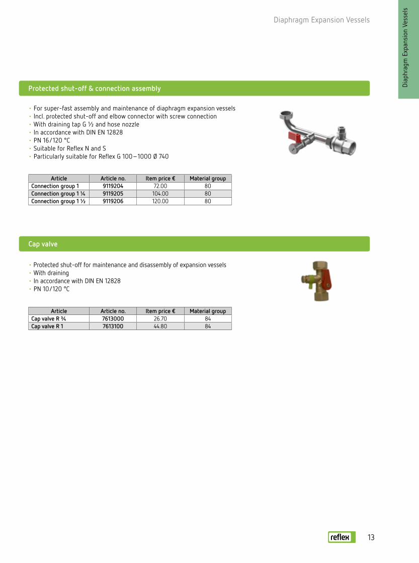
Article Article no. Item price € Material groupConnection group 1 9119204 72.00 80Connection group 1 ¼ 9119205 104.00 80Connection group 1 ½ 9119206 120.00 80
Article Article no. Item price € Material groupCap valve R ¾ 7613000 26.70 84Cap valve R 1 7613100 44.80 84
• For super-fast assembly and maintenance of diaphragm expansion vessels• Incl. protected shut-off and elbow connector with screw connection• With draining tap G ½ and hose nozzle• In accordance with DIN EN 12828• PN 16/120 °C• Suitable for Reflex N and S• Particularly suitable for Reflex G 100–1000 Ø 740
• Protected shut-off for maintenance and disassembly of expansion vessels• With draining• In accordance with DIN EN 12828• PN 10/120 °C
Protected shut-off & connection assembly
Cap valve

Diaphragm Expansion Vessels
Diap
hrag
m E
xpan
sion
Ves
sels
Heating systems: 90/70 °C
H [m]10
Safety valve psv bar 2.5 Vn 3.0 Vn 4.0 Vn 5.0 Vn
Pre-set pressure p0
bar 1.0 1.5 L i -tres
0.5 1.0 1.5 1.8 L i -tres
1.5 2.0 2.5 3.0 L i -tres
2.0 2.5 3.0 3.5 4.0 Litres
Content VA
Litres 30 --- 8 85 50 19 --- 8 55 30 5 --- 8 55 37 16 --- --- 8
45 --- 12 120 75 29 --- 12 80 45 7 --- 12 85 55 24 --- --- 12
85 --- 18 200 130 60 17 18 140 85 28 --- 18 140 100 55 8 --- 18
150 33 25 320 220 120 55 25 230 150 70 --- 25 230 170 110 43 --- 25
240 80 35 470 340 200 110 33 330 240 130 25 33 360 270 180 95 5 33
380 110 50 700 510 320 200 50 540 380 230 70 50 550 420 300 170 43 50
500 170 80 1120 840 440 260 80 870 650 410 120 80 890 710 530 320 95 80
620 210 100 1400 1050 540 330 100 1090 820 430 150 100 1110 890 670 420 120 100
870 300 140 1960 1470 760 460 140 1530 1140 610 200 140 1560 1250 940 510 170 140
1240 420 200 2800 2100 1090 660 200 2180 1630 870 290 200 2230 1780 1340 720 240 200
1550 530 250 3500 2630 1360 820 250 2720 2040 1090 370 250 2790 2230 1670 900 300 250
1860 630 300 4200 3150 1630 990 300 3270 2450 1300 440 300 3340 2670 2010 1080 360 300
2480 850 400 5600 4200 2180 1320 400 4360 3270 1740 580 400 4460 3570 2670 1440 480 400
3100 1060 500 6920 5250 2720 1650 500 5450 4080 2170 730 500 5570 4460 3340 1800 600 500
3720 1270 600 8400 6300 3260 1980 600 6540 4900 2610 880 600 6680 5350 4010 2170 730 600
4970 1690 800 11200 8400 4350 2640 800 8710 6540 3480 1170 800 8910 7130 5350 2890 970 800
6210 2120 1000 13830 10500 5440 3300 1000 10890 8170 4350 1460 1000 11140 8910 6680 3610 1210 1000
Approximate water content:
RadiatorsVA = Q [kW] x 13.5 l/kWPanel-type radiatorsVA = Q [kW] x 8.5 l/kW
Selection example
pSV = 3 barH = 13 mQ = 40 kW (plates 90/70 °C)
VPH = 1000 l (V buffer storage tank) Calculate: → VA = 40 kW x 8.5 l/kW + 1000 = 1340 l → p0 ≥ + 0.2 bar = 1.5 bar
From the table:
With pSV = 3 bar, p0 = 1.5 bar,
VA = 1340 litres
→ Vn = 250 litres (for VA max. 1360)
Selected:
1 x Reflex N 250, 6 bar → p. 7
1 x cap ball valve → p. 131310( )
NNS S
N N
Quick selection table for diaphragm expansion vessels
Reflex recommendations:
- Select sufficiently high safety valve actuation pressure: psv ≥ p0 + 1.5 bar
- If possible, apply a 0.2 bar margin when calculating the gas
input pressure: p0 ≥ + 0.2 bar
- Due to the required supply pressure for the circulating pumps, select an pre-set pressure of at
least 1 bar for roof-mounted systems also: p0 ≥ 1 bar
- In a vented system in cold conditions, set the water-side filling or initial pressure
at least 0.3 bar higher than the pre-set pressure: pfil ≥ p0 + 0.3 bar
Heating systems: 90/70 °C
For detailed calculations, refer to our brochure “Pressurisation Systems - Planning, Calculation, Equipment” or visit www.reflex.de to use our Reflex Pro calculation software
14

15
Diaphragm Expansion Vessels
Diap
hrag
m E
xpan
sion
Ves
sels
The complete solution: Refix DD with Flowjet flow-through valve The Flowjet flow-through valve is easy to install in accordance with DIN requirements, as the shut-off facility, draining capability and flow of the Refix vessel are guaranteed.
25 b
ar10
bar
Refix
Refix DD
• For potable water systems, pressure booster systems and hot water systems in accordance with DIN 1988, stainless steel connection
• Highest hygienic standard by continous flow through the vessel• Diaphragm in accordance with DIN EN 13831, DIN 4807 T5, KTW-C and
W 270• Built and tested in accordance with DIN 4807 T5, DIN DVGW reg. no.
NW-0411AT2534• Approval in accordance with the Pressure Equipment Directive 97/23/EC• Coated outside and inside in compliance with KTW-A• Pre-set pressure 4 bar• Can be combined with Flowjet flow-through valve• 33 litres with suspension brackets
Vn Nominal volume/litres 1) Supplied without T-piece
Type10 bar/70 °C
Article no. Green White
Unit price€
Material group
PU Weightkg
D mm
Hmm
A
DD 2 1) 7381500 – 88.00 48 288 1.0 132 269 G ¾DD 8 7308000 7307700 91.20 48 96 1.7 206 330 G ¾DD 12 7308200 7307800 96.80 48 72 2.0 280 318 G ¾DD 18 7308300 7307900 111.00 48 56 2.5 280 387 G ¾DD 25 7308400 7380400 135.00 48 42 3.3 280 507 G ¾DD 33 7380700 7380800 213.00 48 24 5.8 354 468 G ¾
Type25 bar/70 °C
Article no. Green White
Unit price€
Material group
PU Weightkg
D mm
Hmm
A
DD 8 7290200 7290300 196.00 48 60 3.2 206 336 G ¾
33 litres with suspension brackets
(shown from the rear)8 - 25 litres
T-piece Rp ¾ included (for DD 8 – 33 litres)
Ø DØ D
A
A
HH
ACS
Notes for the installer
• The input pressure side must be adjusted to the water utility company.
Criteria
• When switching a PBS pump on or off, the flow velocity in the connection line must not change by more than 0.15 m/s, and by not more than 0.5 m/s in the event of the failure of all pumps.
• During pump operation, the supply pressure must not drop below 50 % of the minimum value pminS and must be at least 1 bar.

Diaphragm Expansion Vessels
Diap
hrag
m E
xpan
sion
Ves
sels
Reflex wall bracket
• Bracket with tightening strap for 8–25 litre vessels• Ultra-simple assembly
Article no.: 7611000 Unit price: €7.60 Material group 75 PEX 36
Flowjet flow-through valve ¾
• Protected shut-off valve with drainage for Refix DD in accordance with DIN 4807 T5
• Perm. excess operating pressure 16 bar• Perm. operating temperature 70 °C• Connections on both sides G ¾“, m/f thread• Can be combined with T-pieces (on site) with nominal width 1“
Article no.: 9116799 Unit price: €18.00 Material group 85
16

17
Diaphragm Expansion Vessels
Diap
hrag
m E
xpan
sion
Ves
sels
10 b
ar
Refix DT
• For potable water systems, pressure booster systems and hot water systems in accordance with DIN 1988
• Flowjet, incl. shut-off and drainage or duo-connection• Diaphragm in accordance with DIN EN 13831, DIN 4807 T5, KTW-C and W 270• Built and tested in acc. with DIN 4807 T5, DIN DVGW reg. no. NW-0411AT2094• Approval in accordance with the Pressure Equipment Directive 97/23/EC• Coated outside and inside in compliance with KTW-A• Pre-set pressure 4 bar• Diaphragm can be replaced• Incl. pressure gauge• Pressure gauge and pre-set pressure valve protected by metal brackets
Type Connection Article no. Unit price Material Weight Ø D H h10 bar/70 °C Green € group kg mm mm mm
DT 60 Flowjet Rp 1 ¼ 7309000 1,125.00 47 15.0 409 766 80DT 80 Flowjet Rp 1 ¼
DN 50/PN 16DN 65/PN 16DN 80/PN 16
7309100736500073357057335805
1,164.001,187.001,225.001,254.00
47 474747
16.5 23.0 24.0 26.0
480480480480
750750750750
65100110115
DT 100 Flowjet Rp 1 ¼ DN 50/PN 16DN 65/PN 16DN 80/PN 16
7309200736540073654057365406
1,406.001,429.001,466.001,497.00
47474747
18.6 26.0 27.0 28.0
480480480480
856856856856
65100110115
DT 200 Flowjet Rp 1 ¼ DN 50/PN 16DN 65/PN 16DN 80/PN 16
7309300736510073651057365106
1,539.001,562.001,600.001,630.00
47474747
37.053.054.057.0
634634634634
975975975975
80105115120
DT 300 Flowjet Rp 1 ¼ DN 50/PN 16DN 65/PN 16DN 80/PN 16
7309400736520073363057336405
1,633.001,657.001,695.001,723.00
47474747
43.559.0 60.0 63.0
634634634634
1275127512751275
80105115120
DT 400 Flowjet Rp 1 ¼ DN 50/PN 16DN 65/PN 16DN 80/PN 16
7319305736550073365057336605
2,065.002,087.002,126.002,155.00
47474747
73.0 79.0 80.0 83.0
740740740740
1245124512451245
7095105110
DT 500 Flowjet Rp 1 ¼ DN 50/PN 16DN 65/PN 16DN 80/PN 16
7309500736530073653077365305
2,385.002,407.002,447.002,477.00
47474747
69.085.086.089.0
740740740740
1475147514751475
7090100110
DT 600 DN 50/PN 16DN 65/PN 16DN 80/PN 16
736560073367057336806
3,619.003,670.003,702.00
474747
164.0165.0177.4
740740740
186018601860
235235235
DT 800 DN 50/PN 16DN 65/PN 16DN 80/PN 16
736570073369057337006
4,314.004,364.004,396.00
474747
204.0205.0208.0
740740740
232523252325
235235235
DT 1000 Ø 740 DN 50/PN 16DN 65/PN 16DN 80/PN 16
736580073371057337205
5,090.005,139.005,171.00
474747
244.0245.0248.0
740740740
260426042604
235235235
DT 1000 Ø 1000 DN 65/PN 16DN 80/PN 16DN 100/PN 16
732010573373057337405
5,723.005,831.005,974.00
464646
386.2386.2386.2
100010001000
200020002000
160150140
DT 1500 DN 65/PN 16DN 80/PN 16DN 100/PN 16
7320305 73375057337605
6,765.006,871.007,017.00
464646
502.4502.4502.4
120012001200
200020002000
160150140
DT 2000 DN 65/PN 16DN 80/PN 16DN 100/PN 16
732050573377057337805
9,334.009,443.009,584.00
464646
686.5686.5686.5
120012001200
245024502450
160150140
DT 3000 DN 65/PN 16DN 80/PN 16DN 100/PN 16
732070573379057338005
14,802.0014,910.0015,053.00
464646
1054.01057.01057.0
150015001500
252025202520
190180170
Vn Nominal volume/litres
Ø D
H
h
60–500 litres (with Flowjet)
Ø D
H
h
600 – 1000
(Ø 740) litres
A

Diaphragm Expansion Vessels
Diap
hrag
m E
xpan
sion
Ves
sels
16 b
ar
Refix DT (continued)
Type Connection Article no. Unit price Material Weight Ø D H h16 bar/70 °C Green € group kg mm mm mm
DT 80 Flowjet Rp 1 ¼ DN 50/PN 16DN 65/PN 16DN 80/PN 16
7316005737000073103067310307
1,335.001,362.001,406.001,440.00
47 474747
27.0 32.0 33.0 35.0
480480480480
750750750750
65100110115
DT 100 Flowjet Rp 1 ¼ DN 50/PN 16DN 65/PN 16DN 80/PN 16
7365408737010073701017370102
1,613.001,637.001,682.001,716.00
47474747
29.0 34.0 35.0 37.0
480480480480
835835835835
65100110115
DT 200 Flowjet Rp 1 ¼ DN 50/PN 16DN 65/PN 16DN 80/PN 16
7365108737020073702057370206
1,766.001,791.001,836.001,871.00
47474747
55.0 61.0 62.0 65.0
634634634634
975975975975
80105115120
DT 300 Flowjet Rp 1 ¼ DN 50/PN 16DN 65/PN 16DN 80/PN 16
7319205737030073142057314206
1,874.001,900.001,944.001,977.00
47474747
64.0 70.0 71.0 74.0
634634634634
1275127512751275
80105115120
DT 400 DN 50/PN 16DN 65/PN 16DN 80/PN 16
737040073390067339005
2,394.002,437.002,472.00
474747
113.0 119.0 122.0
740740740
139513951395
235235235
DT 500 DN 50/PN 16DN 65/PN 16DN 80/PN 16
737050073705077370505
2,763.002,806.002,840.00
474747
130.0 131.0134.0
740740740
161516151615
235235235
DT 600 DN 50/PN 16DN 65/PN 16DN 80/PN 16
737060073391057339205
3,896.003,940.003,974.00
474747
174.0175.0178.0
740740740
186018601860
235235235
DT 800 DN 50/PN 16DN 65/PN 16DN 80/PN 16
737070073393057339406
4,715.004,758.004,789.00
474747
224.0225.0228.0
740740740
232523252325
235235235
DT 1000 Ø 740 DN 50/PN 16DN 65/PN 16DN 80/PN 16
737080073395057339605
5,641.005,684.005,716.00
474747
259.0260.0263.0
740740740
260426042604
235235235
DT 1000 Ø 1000 DN 65/PN 16DN 80/PN 16DN 100/PN 16
732020573397057339805
6,563.006,670.006,814.00
464646
488.0488.0488.0
100010001000
200020002000
160150140
DT 1500 DN 65/PN 16DN 80/PN 16DN 100/PN 16
732040573399057340005
7,548.007,657.007,798.00
464646
630.0630.0630.0
120012001200
200020002000
160150140
DT 2000 DN 65/PN 16DN 80/PN 16DN 100/PN 16
732060573401057340205
10,809.0010,917.0011,062.00
464646
850.0850.0850.0
120012001200
245024502450
160150140
DT 3000 DN 65/PN 16DN 80/PN 16DN 100/PN 16
732080573403057340405
17,186.0017,295.0017,440.00
464646
1240.01240.01200.0
150015001500
252025202520
190180170
Vn Nominal volume/litres
Ø D
H
h
3000 litres
A
Ø D
H
h
1000 (Ø 1000)–2000 litresA
Special versions >16 bar available on request
• From 1000 litres/Ø 1000 mm with MBM coupling
18
19
Diaphragm Expansion Vessels
Diap
hrag
m E
xpan
sion
Ves
sels
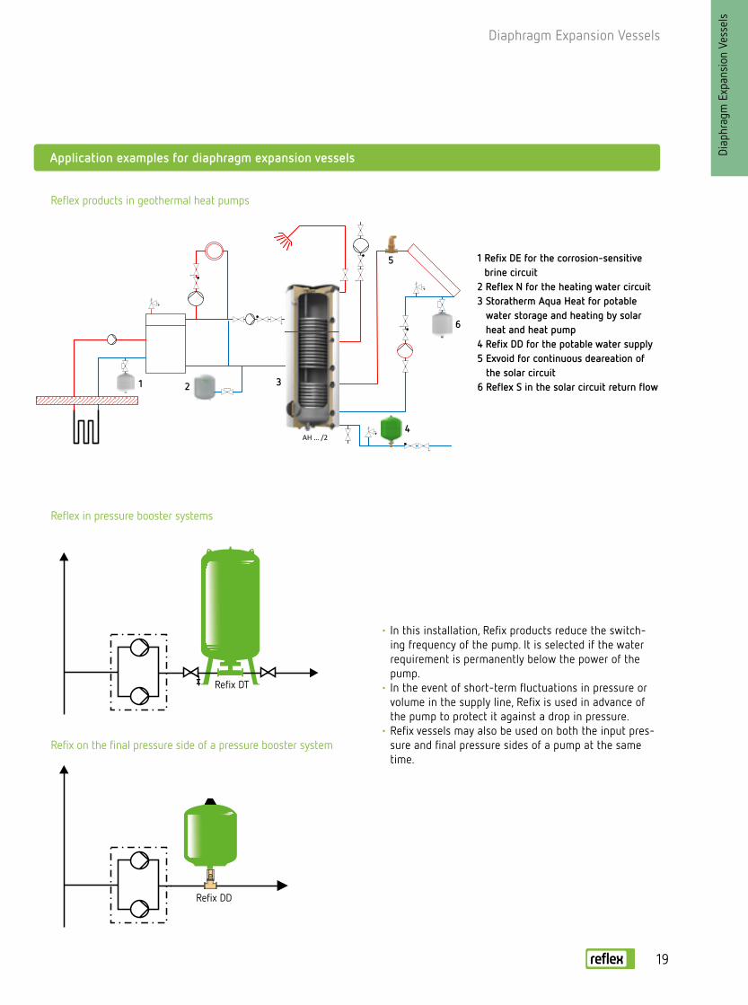
Application examples for diaphragm expansion vessels
Refix DT
• In this installation, Refix products reduce the switch-ing frequency of the pump. It is selected if the water requirement is permanently below the power of the pump.
• In the event of short-term fluctuations in pressure or volume in the supply line, Refix is used in advance of the pump to protect it against a drop in pressure.
• Refix vessels may also be used on both the input pres-sure and final pressure sides of a pump at the same time.
1 Refix DE for the corrosion-sensitive brine circuit
2 Reflex N for the heating water circuit3 Storatherm Aqua Heat for potable
water storage and heating by solar heat and heat pump
4 Refix DD for the potable water supply5 Exvoid for continuous deareation of
the solar circuit6 Reflex S in the solar circuit return flow
Reflex products in geothermal heat pumps
Reflex in pressure booster systems
Refix on the final pressure side of a pressure booster system
AH … /2
1 2 3
4
5
6
Refix DD

10 b
ar
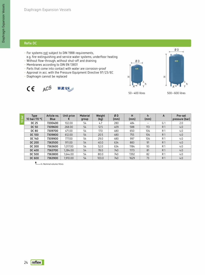
• For systems not subject to DIN 1988 requirements, e.g. fire-extinguishing and service water systems, underfloor heating, geothermal energy
• Without flow-through, without shut-off and discharge• Full diaphragm according to DIN EN 13831/can be replaced from 50 litres• Parts that come into contact with water are corrosion-proof• Approval in acc. with the Pressure Equipment Directive 97/23/EC• Pre-set pressure 4 bar• 33 litres with suspension brackets• From Ø 1000 mm incl. pressure gauge• Pressure gauge and pre-set pressure valve protected
by metal brackets
Diaphragm Expansion Vessels
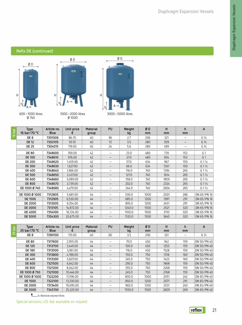
Refix DE
Type 10 bar/70 °C
Article no.Blue
Unit price€
Material group
PU Weightkg
Ø Dmm
Hmm
hmm
A
DE 2 7200300 66.70 40 288 1.0 132 260 – G ¾DE 8 7301000 70.10 40 96 1.7 206 316 – G ¾DE 12 7302000 72.90 40 72 2.4 280 307 – G ¾DE 18 7303000 83.90 40 56 2.8 280 377 – G ¾DE 25 7304000 102.00 40 42 3.7 280 496 – G ¾DE 33 7303900 179.00 40 24 5.7 354 454 – G ¾
DE 33 1) 7305500 179.00 40 24 6.5 354 520 66 G ¾
DE 50 7306005 420.00 42 20 9.5 409 604 102 G 1DE 60 7306400 493.00 42 18 11.2 409 734 161 G 1DE 80 7306500 613.00 42 10 14.0 480 729 153 G 1DE 100 7306600 795.00 42 10 16.0 480 834 153 G 1DE 200 7306700 1,233.00 42 4 36.5 634 967 150 G 1 ¼DE 300 7306800 1,323.00 42 – 41.6 634 1267 150 G 1 ¼DE 400 7306850 1,684.00 42 – 73.0 740 1245 139 G 1 ¼DE 500 7306900 2,138.00 42 – 103.0 740 1475 133 G 1 ¼DE 600 7306950 2,812.00 42 – 128.0 740 1859 263 G 1 ½DE 800 7306960 3,340.00 42 – 176.0 740 2325 263 G 1 ½
DE 1000 Ø 740 7306970 3,927.00 42 – 214.0 740 2604 263 G 1 ½
DE 1000 Ø 1000 7311405 4,953.00 44 – 427.0 1000 2001 286 DN 65/PN 16DE 1500 7311605 5,856.00 44 – 542.0 1200 1991 291 DN 65/PN 16DE 2000 7311705 8,079.00 44 – 717.0 1200 2451 291 DN 65/PN 16DE 3000 7311805 12,805.00 44 – 962.0 1500 2521 320 DN 65/PN 16DE 4000 7354000 14,400.00 44 – 1085.0 1500 3070 320 DN 65/PN 16DE 5000 7354200 17,802.00 44 – 1050.0 1500 3635 320 DN 65/PN 16
Vn nominal volume/litres * ACS symbol applies for DE-2- to DE-33 vessels 1) Vertical design
Ø D
Ø D
A A
H H
h
H
A
2 – 25 litres 50 – 500 litres33 litres
ACS *
Diap
hrag
m E
xpan
sion
Ves
sels
Ø D
20
21
Diaphragm Expansion Vessels25
bar
16 b
ar Type 16 bar/70 °C
Article no.Blue
Unit price€
Material group
PU Weightkg
Ø Dmm
Hmm
hmm
A
DE 8 7301006 86.70 40 96 2.7 206 321 – G ¾DE 12 7302105 93.10 40 72 3.5 280 309 – G ¾DE 25 7304015 119.00 40 24 5.6 280 499 – G ¾
DE 80 7348600 769.00 42 – 23.0 480 729 153 G 1DE 100 7348610 976.00 42 – 27.0 480 834 153 G 1DE 200 7348620 1,459.00 42 – 57.0 634 967 150 G 1 ¼DE 300 7348630 1,627.00 42 – 66.0 634 1267 150 G 1 ¼DE 400 7348640 1,966.00 42 – 116.0 740 1394 265 G 1 ½DE 500 7348650 2,437.00 42 – 127.0 740 1614 265 G 1 ½DE 600 7348660 3,089.00 42 – 158.0 740 1859 265 G 1 ½DE 800 7348670 3,739.00 42 – 202.0 740 2324 265 G 1 ½
DE 1000 Ø 740 7348680 4,479.00 42 – 244.0 740 2604 265 G 1 ½
DE 1000 Ø 1000 7312805 5,681.00 44 – 530.0 1000 2001 286 DN 65/PN 16DE 1500 7312905 6,530.00 44 – 685.0 1200 1991 291 DN 65/PN 16DE 2000 7313005 9,354.00 44 – 895.0 1200 2451 291 DN 65/PN 16DE 3000 7313105 14,872.00 44 – 1240.0 1500 2521 320 DN 65/PN 16DE 4000 7354100 16,724.00 44 – 1100.0 1500 3110 320 DN 65/PN 16DE 5000 7354300 20,675.00 44 – 1120.0 1500 3645 320 DN 65/PN 16
Refix DE (continued)
Type 25 bar/70 °C
Article no.Blue
Unit price€
Material group
PU Weightkg
Ø Dmm
Hmm
hmm
A
DE 8 7290100 115.00 40 60 3.5 206 321 – G ¾
DE 80 7317600 2,955.00 44 – 70.0 450 942 159 DN 50/PN 40DE 120 7313700 3,449.00 44 – 100.0 450 1253 159 DN 50/PN 40DE 180 7313500 3,961.00 44 – 116.0 450 1528 159 DN 50/PN 40DE 300 7313800 4,788.00 44 – 150.0 750 1318 160 DN 50/PN 40DE 400 7313300 5,607.00 44 – 245.0 750 1423 160 DN 50/PN 40DE 600 7321500 6,642.00 44 – 290.0 750 1868 159 DN 50/PN 40DE 800 7321200 8,042.00 44 – 355.0 750 2268 159 DN 50/PN 40
DE 1000 Ø 750 7321000 10,446.00 44 – 245.0 750 2768 159 DN 50/PN 40DE 1000 Ø 1000 7322200 11,596.00 44 – 800.0 1000 2051 242 DN 65/PN 40
DE 1500 7322100 13,330.00 44 – 850.0 1200 2071 291 DN 65/PN 40DE 2000 7313400 19,095.00 44 – 960.0 1200 2531 240 DN 65/PN 40DE 3000 7345700 25,220.00 44 – 1550.0 1500 2609 269 DN 65/PN 40
Vn Nominal volume/litres
600 – 1000 litresØ 740
1000 – 2000 litresØ 1000
3000 – 5000 litres
Ø D Ø D
Ø D
A
H
hA
A
H H
hh
Special versions >25 bar available on request
Diap
hrag
m E
xpan
sion
Ves
sels

DT
DDDD
DT
Diaphragm Expansion Vessels
Diap
hrag
m E
xpan
sion
Ves
sels
Selection according to nominal volume Vn
Selected
10 °C Cold water inlet temperature
60 °C Storage tank temperature
psv [bar] 6 7 8 10
VSt [litres] Refix nominal volume [litres]
90 8 8 8 8100 8 8 8 8120 8 8 8 8130 8 8 8 8150 8 8 8 8180 12 8 8 8200 12 12 8 8250 12 12 12 8300 18 18 12 12400 25 18 18 18500 25 25 18 18600 33 25 25 18700 33 33 25 25800 60 33 33 25900 60 60 33 25
1000 60 60 33 331500 80 80 60 602000 100 100 80 803000 200 200 100 100
Quick selection table for Refix
pa pSVVn p0
VSt
Gas input pressure p0 = 3.0 bar
Set pressure of pressure reducing valve pa ≥ 3.2 bar
Gas input pressure p0 = 4.0 bar = standard
Set pressure of pressure reducing valve pa ≥ 4.2 bar
psv [bar] 6 7 8 10
VSt [litres] Refix nominal volume [litres]
90 8 8 8 8100 12 8 8 8120 12 8 8 8130 12 8 8 8150 18 12 8 8180 18 12 8 8200 18 12 12 8250 25 18 12 12300 25 18 18 12400 33 33 18 18500 60 33 25 18600 60 60 25 25700 60 60 33 25800 80 60 60 25900 80 60 60 33
1000 100 60 60 601500 200 100 80 602000 200 200 100 803000 300 200 200 100
Selection example
Storage volume (VSt) 900 litres
Hot water temperature (THw) 60 °C
Set pressure of pressure reducing valve (pi) 4.2 bar
Safety valve (pSV) 10.0 bar
Expansion (60 °C/10 °C) (n) 1.7 %
Pre-set pressure (p0) 4.0 bar
Nominal volume (Vn) 31.5 litres
V SV
22
Diaphragm Expansion Vessels
Diap
hrag
m E
xpan
sion
Ves
sels
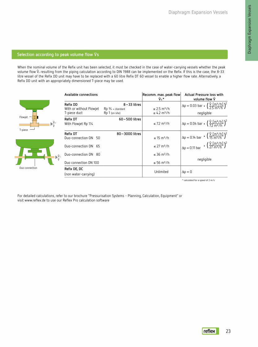
For detailed calculations, refer to our brochure “Pressurisation Systems - Planning, Calculation, Equipment” or visit www.reflex.de to use our Reflex Pro calculation software
When the nominal volume of the Refix unit has been selected, it must be checked in the case of water-carrying vessels whether the peak volume flow V s resulting from the piping calculation according to DIN 1988 can be implemented on the Refix. If this is the case, the 8-33 litre vessel of the Refix DD unit may have to be replaced with a 60 litre Refix DT 60 vessel to enable a higher flow rate. Alternatively, a Refix DD unit with an appropriately dimensioned T-piece may be used.
Flowjet
T-piece
Duo connection
Selection according to peak volume flow V s
* calculated for a speed of 2 m/s
V [m³/h] 2.5 m³/h
V [m³/h] 7.2 m³/h
V [m³/h] 15 m³/h
V [m³/h] 27 m³/h
( )2
( )2
( )2
( )2
Available connections Recomm. max. peak flow V S *
Actual Pressure loss with volume flow V
Refix DDWith or without FlowjetT-piece duct
8 – 33 litresRp ¾ = standardRp 1 (on site)
≤ 2.5 m³/h≤ 4.2 m³/h
∆p = 0.03 bar
negligible
Refix DTWith Flowjet Rp 1¼
60 – 500 litres≤ 7.2 m³/h ∆p = 0.04 bar
Refix DTDuo-connection DN 50
Duo-connection DN 65
Duo-connection DN 80
Duo connection DN 100
80 – 3000 litres ≤ 15 m³/h
≤ 27 m³/h
≤ 36 m³/h
≤ 56 m³/h
∆p = 0.14 bar
∆p = 0.11 bar
negligible
Refix DE, DC(non water-carrying)
Unlimited ∆p = 0
V S V
V S V
23
Diaphragm Expansion Vessels
• For systems not subject to DIN 1988 requirements, e.g. fire-extinguishing and service water systems, underfloor heating
• Without flow-through, without shut-off and draining• Membranes according to DIN EN 13831• Parts that come into contact with water are corrosion-proof• Approval in acc. with the Pressure Equipment Directive 97/23/EC• Diaphragm cannot be replaced
Refix DC
Type10 bar/70 °C
Article no.Blue
Unit price€
Material group
Weight (kg)
Ø D (mm)
H (mm)
h (mm)
A Pre-set pressure (bar)
DC 25 7200400 102.00 54 4.7 280 484 – G 1 2.0DC 50 7309600 268.00 54 12.5 409 588 113 R 1 4.0DC 80 7309700 471.00 54 17.0 480 650 104 R 1 4.0DC 100 7309800 612.00 54 20.5 480 755 104 R 1 4.0DC 140 7309900 777.00 54 29.0 480 997 104 R 1 4.0DC 200 7363500 911.00 54 40.0 634 883 91 R 1 4.0DC 300 7363600 1,017.00 54 52.0 634 1184 93 R 1 4.0DC 400 7363700 1,284.00 54 78.0 740 1173 81 R 1 4.0DC 500 7363800 1,644.00 54 80.0 740 1392 82 R 1 4.0DC 600 7363900 1,910.00 54 103.0 740 1629 73 R 1 4.0
Vn Nominal volume/litres
Ø D
Ø D
H H
h hAA
50 – 400 litresACS
500 – 600 litres
10 b
ar
Diap
hrag
m E
xpan
sion
Ves
sels
24

25
• For devices with quick-close valves, e.g. washing machines, automatic dishwashers • Approval in acc. with the Pressure Equipment Directive 97/23/EC• Total volume 165 cm³ • Pre-set pressure 4 bar• 10 bar/70 °C Article no.: 7351000 Unit price: €34.40 Material group 74
Water shock arrestor
Diaphragm Expansion Vessels
∅ 86
115
G ½
Diap
hrag
m E
xpan
sion
Ves
sels
For example, upstream of washing machines, dishwashers, automatic flush valves, gas combi heaters

Diap
hrag
m E
xpan
sion
Ves
sels
• For use as buffer vessel for domestic water systems that are not subject to DIN 1988 requirements
• Vessel surface and parts that come into contact with the water are plastic-coated
• Diaphragm can be replaced at HW 50–HW 100• Pre-set pressure 2 bar
Refix HW
Type10 bar/70 °C
Article no.Blue
Unit price€
Material group
PU Weightkg
Ø Dmm
Hmm
L mm
F mm
W mm
C mm
A
HW 25 7200310 117.00 49 36 5.3 280 293.4 484 228 214 270 G ¾HW 50 7200320 284.00 49 20 15.0 409 433 503 175 285 350 G ¾HW 80 7200340 480.00 49 – 17.0 480 494 576 230 285 355 G 1HW 100 7200350 654.00 49 – 15.0 480 494 681 340 285 355 G 1
Vn Nominal volume/litres
Digital test manometer
• Reflex pre-set pressure gauge up to around 9 bar Article no.: 9119198 Unit price: €17.00 Material group 86
ACS
• Signals in the event of diaphragm rupture in the Refix DT, DE and Reflex G from 60 litres • Consisting of an electrode relay and an electrode (factory-fitted)• Voltage supply 230 V/50 Hz• Floating output (changeover switch)• Only supplied in conjunction with a vessel
Article no.: 7857700 Unit price: €330.00 Material group 86
Diaphragm rupture detector
H
Ø D
WW2
LL2
A
10 b
ar
26

Pressurisation Systems
Diap
hrag
m E
xpan
sion
Ves
sels
Pres
suris
atio
n Sy
stem
s

Pressurisation Systems
Diap
hrag
m E
xpan
sion
Ves
sels
• 2-line LCD display• 8 control keys• 2 status displays• Integrated control of system pressure, deaeration and
water make-up• Manual and automatic operation• Floating external common error message• Floating input, e.g. for contact water meter• RS-485 interface for control panel connection
Control Basic controller
• 4.3" touch screen colour display• Graphic user interface• Simply structured plain text menus including operating instruc-
tions and help texts• Integrated control of system pressure, deaeration and water
make-up• Manual and automatic operation• Permanent display of the most important operating parameters
in the system diagram• Intelligent Plug & Play operational management• Evaluation and storage of the most important operational data• Extensive interfaces:
– 1 x floating input, e.g. for contact water meter– 2 x floating outputs for error messages– 2 x analogue parametrisable outputs for pressure and level– 2 x RS-485 interfaces for control panel connection and further
networking– Plugs for Bluetooth module, HMS networks and KNX module,
as well as SD card
Control Touch controller
Pres
suris
atio
n Sy
stem
s
Control unit
28

29
Pressurisation Systems
Reflexomat
Diap
hrag
m E
xpan
sion
Ves
sels
Pres
suris
atio
n Sy
stem
s
Reflex Fillset
Expansion line
RS control unit
RG basic vessel
Make-up water
RS 90/1 230 V / 50 Hz from RS 150/1 400 V, 50 HzConfigurable floating common error message + RS-485 (from RS 90/2)
Reflex MV with ball valve
P
WM
LIS Water make-up
Water make-up in the event of system-based water losses is integrated into the Reflexomat controls. It is performed based on the filling level in the basic vessel. The level measurement is carried out by evaluating the weight of the basic vessel. The solenoid valve for water make-up and the Reflex Fillset with water meter and system separator can be ordered optionally. Water make-up is monitored by a leakage monitor and interrupted in the event of any malfunctions. The signals of a contact water meter can be evaluated (Reflex Fillset with contact water meter). The Reflex Fillcontrol Auto make-up station with integrated pump is available for very high system pressures.
PIS Pressure maintenance, compensating for the expansion volume
The compressor and solenoid valve are actuated in such a way that if pressure is maintained at approximately ± 0.1 bar, the expansion water flowing in or out via expansion line P is compensated for in the basic vessel. Because pressure is "stored" in the form of an air buffer in the expansion vessel (basic vessel), the method of operation is very gentle. Reflexomats with 2 compressors work with load-based, automatically alternating operation and automatic malfunction switchover.
Reflexomat with a compressor for systems up to 12 MW

Pressurisation Systems
Diap
hrag
m E
xpan
sion
Ves
sels
Pres
suris
atio
n Sy
stem
s
Reflexomat – compressor-controlled dynamic pressure maintenance
Reflexomat with RS 300/1 control unit and RG 1000 basic vessel
• A Reflexomat always consists of the control unit and the expansion vessel
• For systems with up to a 600 l vessel volume, the controller is mounted with the compressor on the vessel
• Larger expansion volumes can be implemented, both in accordance with large vessels as well as through a serial circuit of a basic vessel and one or several secondary vessels
• Reflexomat systems are also available without a compressor, if a compressed air supply is available on-site
30

31
Pressurisation Systems
Diap
hrag
m E
xpan
sion
Ves
sels
Pres
suris
atio
n Sy
stem
s
• Compact compressor-controlled pressurisation system for heating and cooling water systems
• Approval in acc. with the Pressure Equipment Directive 97/23/EC
• Membranes according to DIN EN 13831• Perm. excess operating pressure 6 bar• Perm. advance temperature 120 °C*• Perm. operating temperature 70 °C**• Perm. ambient temperature 0–45 °C• Degree of protection: IP 54• With Control Basic• Power supply 230 V• Collective error signal and RS 485 interface
Type Article no. Unit price€
Material group Ø Dmm
Hmm
hmm
System connection
Weightkg
RC 200 8806405 4,085.00 31 634 1320 135 R 1 52.0RC 300 8801705 4,319.00 31 634 1620 135 R 1 69.0RC 400 8802805 4,425.00 31 740 1620 135 R 1 80.0RC 500 8803705 4,800.00 31 740 1745 135 R 1 93.0
Commissioning (optional) by Reflex Customer Service Article no.: 7945600 Price: Price on request1) 1) Services not discountable
Ø D
h
H
Reflexomat Compact
* According to maximum possible setting value - Temperature control 105 °C, in accordance with DIN EN 12828
** Installation in the system return, diaphragm load of expansion vessels max. 70 °C. Please consult us for permanent temperatures of ≤ 0 °C

Pressurisation Systems
Reflexomat control units
Wall mount
• Compressor-controlled pressurisation system for heating and cooling water systems
• Perm. flow temperature 120 °C*• Perm. operating temperature 70 °C**• Perm. ambient temperature 0–45 °C• Degree of protection: IP 54• Power supply 230 or 400 V• Collective error signal and RS 485 interface• Control Touch from RS 150 as standard• Control Touch: graphic menu display, permanent display of
the operating parameters, extensive interfac-es, e.g. for control panel connection, remote monitoring and system expansion
• Control Touch is also available for RS90
• For user-friendly installation of the RS control unit in conjunction with RG 600 basic vessels (observe installation height H/HG)
• Incl. 3 m long connection hoses
Article no.: 7881900 Unit price: €170.00 Material group 35
Type Article no. Unit price€
Material group
Heightmm
Widthmm
Depthmm
Weightkg
Compressor
RS 90/1 8880111 3,164.00 33 415 395 520 21.0Up to 600 l
RS 90/1 on the basic vessel
RS 90/1 8880211 3,214.00 33 690 395 345 25.0 From 800 l RS 90/1 adjacent
RS 150/1 8880311 4,576.00 33 920 395 600 28.0
adjacentRS 300/1 8880411 5,149.00 33 920 395 700 34.0RS 400/1 8880511 6,098.00 33 920 395 700 51.0RS 580/1 8880611 7,656.00 33 920 395 700 102.0
Type Article no. Unit price€
Material group
Heightmm
Widthmm
Depthmm
Weightkg
Compressors
RS 90/2 8882100 4,740.00 33 920 1225 800 33.0
adjacentRS 150/2 8883100 6,509.00 33 920 1225 800 45.0RS 300/2 8884100 7,976.00 33 920 1225 800 61.0RS 400/2 8885100 9,516.00 33 920 1225 800 95.0RS 580/2 8886100 12,737.00 33 920 1225 800 197.0
RS control unit with 1 compressor
RS control unit with 2 compressors
Voltage 230 V/50 Hz; from RS 150 400 V/50 Hz
* According to maximum possible setting value - Temperature control 105 °C, in accordance with DIN EN 12828** Installation in the system return, diaphragm load of expansion vessels max. 70 °C. Please consult us for permanent temperatures of ≤ 0 °C
H
DW
Pres
suris
atio
n Sy
stem
sDi
aphr
agm
Exp
ansi
on V
esse
ls
32
33
Pressurisation Systems
Diap
hrag
m E
xpan
sion
Ves
sels
Pres
suris
atio
n Sy
stem
s
6 ba
r10
bar
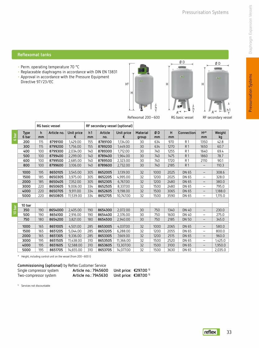
Reflexomat tanks
Commissioning (optional) by Reflex Customer Service Single compressor system Article no.: 7945600 Unit price: €297.00 1)
Two-compressor system Article no.: 7945630 Unit price: €387.00 1)
1) Services not discountable
Ø D
H
h 1
Type6 bar
hmm
Article no. Unit price€
h 1mm
Article no.
Unit price€
Material group
Ø Dmm
Hmm
Connection HG*mm
Weightkg
200 115 8799100 1,429.00 155 8789100 1,134.00 30 634 970 R 1 1350 42.8300 115 8799200 1,756.00 155 8789200 1,449.00 30 634 1270 R 1 1650 60.7400 100 8799300 2,034.00 140 8789300 1,712.00 30 740 1255 R 1 1640 69.4500 100 8799400 2,299.00 140 8789400 1,964.00 30 740 1475 R 1 1860 78.7600 100 8799500 2,685.00 140 8789500 2,323.00 30 740 1720 R 1 2110 90.1800 100 8799600 3,106.00 140 8789600 2,732.00 30 740 2185 R 1 – 110.3
1000 195 8650105 3,545.00 305 8652005 3,139.00 32 1000 2025 DN 65 – 308.61500 185 8650305 3,975.00 305 8652205 4,995.00 32 1200 2025 DN 65 – 328.02000 185 8650405 7,352.00 305 8652305 6,767.00 32 1200 2480 DN 65 – 380.03000 220 8650605 9,006.00 334 8652505 8,337.00 32 1500 2480 DN 65 – 795.04000 220 8650705 9,911.00 334 8652605 9,198.00 32 1500 3065 DN 65 – 1,188.05000 220 8650805 11,539.00 334 8652705 10,747.00 32 1500 3590 DN 65 – 1,115.0
10 bar350 190 8654000 2,405.00 190 8654300 2,072.00 30 750 1340 DN 40 – 230.0500 190 8654100 2,916.00 190 8654400 2,376.00 30 750 1600 DN 40 – 275.0750 180 8654200 3,821.00 180 8654500 2,940.00 30 750 2185 DN 50 – 345.0
1000 165 8651005 4,501.00 285 8653005 4,037.00 32 1000 2065 DN 65 – 580.01500 165 8651205 5,044.00 285 8653205 6,288.00 32 1200 2055 DN 65 – 800.02000 165 8651305 9,336.00 285 8653305 7,669.00 32 1200 2515 DN 65 – 960.03000 195 8651505 11,438.00 310 8653505 11,366.00 32 1500 2520 DN 65 – 1,425.04000 195 8651605 12,588.00 310 8653605 13,307.00 32 1500 3100 DN 65 – 1,950.05000 195 8651705 14,655.00 310 8653705 14,077.00 32 1500 3630 DN 65 – 2,035.0
RG basic vessel RF secondary vessel (optional)
* Height, including control unit on the vessel (from 200–600 l)
Ø D
HHG
H
hhA A
• Perm. operating temperature 70 °C• Replaceable diaphragms in accordance with DIN EN 13831• Approval in accordance with the Pressure Equipment
Directive 97/23/EC
Reflexomat 200 – 600 RG basic vessel RF secondary vessel

Pressurisation Systems
Pres
suris
atio
n Sy
stem
sDi
aphr
agm
Exp
ansi
on V
esse
ls
The circuits must be adjusted to suit local conditions
Master-Slave Connect
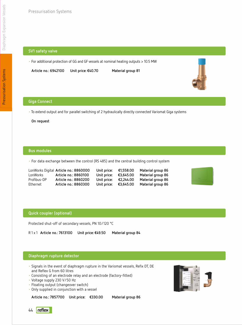
Bus modules
• Software tool for operating up to 10 Reflexomats in a hydraulic group to a distance of 1000 m Article no.: 7859000 Unit price: €295.00 Material group 35
• For data exchange between the controller (RS 485) and the central building control system
LonWorks Digital Article no.: 8860000 Unit price: €1,558.00 Material group 86LonWorks Article no.: 8860100 Unit price: €3,645.00 Material group 86Profibus-DP Article no.: 8860200 Unit price: €2,244.00 Material group 86Ethernet Article no.: 8860300 Unit price: €3,645.00 Material group 86
Reflexomat control unit without compressor (for on-site compressed air)
Surcharge for solenoid valve for supply of on-site, oil-free compressed air (fitted ready-to-connect in the RS 90/1 control unit without compressor)
MV ¼ Article no.: 7913000 Unit price: €200.00 Material group 35
Type Article no. Item price € Material group H/W/D (mm)* Weight (kg)*up to 600 l RS 90/1 8881100 2,636.00 33 415/395/520 9.0above 800 l RS 90/1 8881105 2,684.00 33 690/395/345 9.0
* without compressor
I/O modules
• Two additional analogue outputs for controlling pressure and level • Six freely programmable digital inputs • Six freely programmable floating outputs Article no.: 8858405 Unit price: €1,203.00 Material group 35
• Signals in the event of diaphragm rupture in Reflexomat vessels, Refix DT, DE and Reflex G from 60 litres
• Consisting of an electrode relay and an electrode (factory-fitted)• Voltage supply 230 V/50 Hz• Floating output (changeover switch)• Only supplied in conjunction with a vessel
Article no.: 7857700 Unit price: €330.00 Material group 86
Diaphragm rupture detector
34

Pressurisation Systems
Diap
hrag
m E
xpan
sion
Ves
sels
Pres
suris
atio
n Sy
stem
s
Variomat
Variomat – pump-controlled dynamic pressure maintenance
• Pump-controlled pressurisation system with integral water-make-up and deaeration for heating and cooling water systems
• A Variomat always consists of the control unit, the expansion vessel and a connection set
• Larger expansion volumes can be implemented, both in accordance with large vessels as well as through a serial circuit of a basic vessel and one or several secondary vessels
Variomat with VS 2-2/60 control unit and VG 500 basic vessel
* without compressor
LIS Water make-up
• The volume of discharged free gases and water losses are automatically replenished. The level measurement is carried out by evaluating the weight of the basic vessel. Water make-up based on the filling level in the basic vessel is monitored by a leakage monitor and interrupted in the event of any malfunctions. With the Variomat 2, the signals of a contact water meter can be evaluated (Reflex Fillset with contact water meter).
PIS Pressure maintenance, compensating for the expansion volume
The pump and overflow valve are actuated in such a way that pressure remains constant within a range of around ±0.2 bar. The expansion water is supplied to or discharged from the depressur-ised basic vessel in 2 separate expansion lines.
Variomat 1 with a pump and basic vessel on a heating system up to 2 MW
TIME Deaeration
A part flow of the heating water is released into the basic vessel and thus degassed. The deaeration mode can be selected from the following versions:• Continuous deaeration: constant deaeration after start-
up and repairs in the supply system, to allow all residual air to be removed from the system.
• Follow-up deaeration: activated automatically after continuous deaeration and performed after every pump operation.
• Interval deaeration: performed after a specified schedule.
35

Pressurisation Systems
Pres
suris
atio
n Sy
stem
sDi
aphr
agm
Exp
ansi
on V
esse
ls
• Approval in acc. with the Pressure Equipment Directive 97/23/EC
• Variomat controller VS 1 with Control Basic • From Variomat controller VS 2 with Control Touch and
soft start (alternatively, also available for VS 1)• Perm. advance temperature 120 °C*• Perm. operating temperature 70 °C**• Perm. ambient temperature 0–45 °C• Sound level approx. 55 dB• Degree of protection: IP 54• Water make-up connection Rp ½• Pump/overflow valve connection Rp 1/Rp 1• Collective error signal and RS 485 interface
Type Article no. Item price €
Material group
p0
barHeight
mmWidthmm
Depthmm
Basic vessel Weightkg
VS 1 8910100 4,002.00 38 ≤ 2.5 680 530 580 2 x G 1 25.0VS 2-1/60 8910200 4,967.00 38 ≤ 4.8 920 470 730 2 x G 1 33.0VS 2-1/75 8910300 5,740.00 38 ≤ 6.5 920 530 640 2 x G 1 35.0VS 2-1/95 8910400 5,956.00 38 ≤ 8.0 920 530 640 2 x G 1 37.0
Type Article no. Item price €
Material group
p0
barHeight
mmWidthmm
Depthmm
Basic vessel Weightkg
VS 2-2/35 8911100 7,084.00 38 ≤ 2.5 920 700 780 2 x G 1 ¼ 54.0VS 2-2/60 8911200 7,366.00 38 ≤ 4.8 920 700 780 2 x G 1 ¼ 58.0VS 2-2/75 8911300 8,640.00 38 ≤ 6.5 920 720 800 2 x G 1 ¼ 72.0VS 2-2/95 8911400 9,063.00 38 ≤ 8.0 920 720 800 2 x G 1 ¼ 76.0
Control unit with 1 pump
Control unit with 2 pumps
p0 = Setting value on the control = static height + evaporation pressure + 0.2 bar (recommended)
* According to maximum possible setting value - Temperature control 105 °C, in accordance with DIN EN 12828** Installation in the system return, diaphragm load of expansion vessels max. 70 °C. Please consult us for permanent temperatures of ≤ 0 °C
Variomat control units
H
DW
H
DWVariomat VS 2-1/60 Variomat VS 2-2/95
36

Pressurisation Systems
Ø D Ø D
HH
h h
VG basic vessel VF secondary vessel
Variomat vessels
Type
Article no. Item price €
Article no. Item price €
Material group
Ø Dmm
Hmm
hmm
Connec-tion
Weightkg
200 8600011 1,241.00 8610000 955.00 36 634 1060 146 G 1 41.4300 8600111 1,377.00 8610100 1,092.00 36 634 1360 146 G 1 52.2400 8600211 1,553.00 8610200 1,267.00 36 740 1345 133 G 1 72.2500 8600311 1,716.00 8610300 1,429.00 36 740 1560 133 G 1 81.8600 8600411 1,989.00 8610400 1,704.00 36 740 1810 133 G 1 96.8800 8600511 2,272.00 8610500 2,041.00 36 740 2275 133 G 1 109.9
1000 Ø 740 8600611 2,558.00 8610600 2,327.00 36 740 2685 133 G 1 156.0
1000 Ø 1000 8600705 3,215.00 8610705 3,023.00 37 1000 2130 350 G 1 292.81500 8600905 4,509.00 8610905 4,331.00 37 1200 2130 350 G 1 320.02000 8601005 5,501.00 8611005 5,305.00 37 1200 2590 350 G 1 565.03000 8601205 8,484.00 8611205 8,287.00 37 1500 2590 380 G 1 795.04000 8601305 9,199.00 8611305 9,001.00 37 1500 3160 380 G 1 1080.05000 8601405 10,018.00 8611405 9,821.00 37 1500 3695 380 G 1 1115.0
* Optional
VG basic vessel VF secondary vessel*
• Approval in acc. with the Pressure Equipment Directive 97/23/EC
• Replaceable diaphragm in accordance with DIN EN 13831
Diap
hrag
m E
xpan
sion
Ves
sels
Pres
suris
atio
n Sy
stem
s
37

Pressurisation Systems
Variomat G 1 connection set
Variomat connection set
• For connecting Variomat pump systems to VG basic vessels with protected shut-offs and screw connections
• For connecting Variomat two-pump systems to VG basic vessels
VG vessel (Ø/mm) Article no. Item price € Material group Weight (kg)480–740 6940100 160.00 39 2.0
1000-1500 6940200 182.00 39 3.0
VG vessel (Ø/mm) Article no. Item price € Material group Weight (kg)480–740 6940300 182.00 39 2.0
1000-1500 6940400 219.00 39 3.0
Pres
suris
atio
n Sy
stem
sDi
aphr
agm
Exp
ansi
on V
esse
ls
I/O modules
• Two additional analogue outputs for controlling pressure and level • Six freely programmable digital inputs • Six freely programmable floating outputs• Standard in the GS 3 Variomat Giga controller Article no.: 8997705 Unit price: €1,203.00 Material group 39
38

Pressurisation Systems
Thermal insulation for Variomat vessels
Variomat VS 2-2/60 with VG 500 basic vessel and VW 500 thermal insulation
Type
Article no. Item price €
Material group
Ø Dmm
Hmm
hmm
Connection Weightkg
200 7985700 180.00 39 634 1060 146 G 1 3.0300 7986000 197.00 39 634 1360 146 G 1 3.5400 7995600 214.00 39 740 1345 133 G 1 4.5500 7983900 222.00 39 740 1560 133 G 1 5.5600 7995700 285.00 39 740 1810 133 G 1 6.0800 7993800 296.00 39 740 2275 133 G 1 8.0
1000 Ø 740 7993900 318.00 39 740 2685 133 G 1 8.0
1000 Ø 1000 7986800 318.00 39 1000 2130 350 G 1 10.01500 7987000 355.00 39 1200 2130 350 G 1 12.52000 7987100 393.00 39 1200 2590 350 G 1 15.03000 7993200 496.00 39 1500 2590 380 G 1 16.04000 7993300 560.00 39 1500 3160 380 G 1 18.05000 7993400 616.00 39 1500 3695 380 G 1 24.0
VW thermal insulation* for VG basic vessels
* Optional
Commissioning (optional) by Reflex Customer Service Single-pump system Article no.: 7945600 Unit price: Price on request1)
Dual-pump system Article no.: 7945630 Unit price: Price on request1)
1) Services not discountable
• 50 mm flexible foam thermal insulation with laminated orange PE cladding with zip fastener
Diap
hrag
m E
xpan
sion
Ves
sels
Pres
suris
atio
n Sy
stem
s
39

Pressurisation Systems
Pres
suris
atio
n Sy
stem
sDi
aphr
agm
Exp
ansi
on V
esse
ls
Selecting Variomat control units
Variomat basic and secondary vessel selection
For cooling water systems up to 30 °C, only 50 % of the nominal heat output is to be considered when selecting the control unit
In the green range of outputs ≤ 500 kW and Vn < 200 litres, we recommend using Reflex Servitec + Reflex instead
Minimum operating pressure p0/bar
Perm. operating temperature 70 °C
Height x Width x Depth 304 x 291 x 91 mm
Nominal volume Vn Approximate from diagram or calculation according to formula
0.2 bar [≤ 100 °C]
p0 ≥ H[m]
10 +0.5 bar [ 105 °C]
0.7 bar [ 110 °C]
1.2 bar [ 120 °C]
Safety temperature
H = static height
System flow temperature
Vn = Nominal volumeVA = Water content in the system
0.031 [ 70 °C]
Vn ≥ VA x0.045 [ 90 °C]
0.054 [ 100 °C]
0.063 [ 110 °C]
The nominal volume can can be distrib-uted across multiple vessels (VG basic and VF secondary vessels).
Q /MW Q /MW
p0 bar
p0 bar
Variomat 1, Variomat 2-1 Control unit with 1 pump
Variomat 2-2 Control unit with 2 pumps
Variomat 2-1/95*
Variomat 2-1/75*
Variomat 2-1/60
Variomat 1p0 = 1.3 bar min. setting value for continuous deaeration mode
p0 = 1.3 bar min. setting value for continuous deaeration mode
Variomat 2-2/95*
Variomat 2-2/75*
Variomat 2-2/60
Variomat 2-2/35
Total heat output of heat generation system
In output ranges > 2 MW we recom-mend using two-pump systems
Per pump and overflow valve 50 % of the total output
Q /MWInstalled heat performance in heating surfaces
6 l/kW convectors8.5 l/kW plates/ventilation
13.5 l/kW radiators
20 l/kW
Guideline values for 90/70 °C Heating systems
1 2 3 4
Vn
Litres
Basic and secondary vessels
Selection example
- Output of heat generator Q = 1000 kW- Water content VA = unknown
→ Approximate from the installed heating output Q = 1000 kW, radiators, 90/70 °C, no additional pipelines
- Design temperature = 90 °C- Safety temperature = 110 °C- Static height = 25 m → p0 ≥ bar + 0.7 bar [110 °C]
p0 ≥ bar + 0.7 bar = 3.2 bar
→ Vn from diagram = 600 litres
Selected: Variomat 2-1/60 control unit
+ Basic vessel 600 → p. 37 + Reflex Fillset → p. 47
+ Connection set → p. 38 – We recommend two-pump
systems from 2 MW
– The secondary vessel does
not require any thermal insulation
H [m]10 25 10
40

Pressurisation Systems
Variomat Giga
• Pump-controlled pressure maintenance for particularly high outputs and pressures. For example, in district heating systems and industrial heating and cooling supplies
• Designed for the highest level of reliability• Special systems for temperatures > 110 °C and vessel volumes of up
to 20,000 litres possible• A Variomat Giga always consists of the control unit, the hydraulic
module, the vessel and, if necessary, further options• Larger expansion volumes can be implemented, both in accordance
with large vessels as well as through a serial circuit of a basic vessel and one or several secondary vessels
Variomat Giga
Diap
hrag
m E
xpan
sion
Ves
sels
Pres
suris
atio
n Sy
stem
s
Variomat Giga with basic and secondary vessels on the heating system
41

Pressurisation Systems
Pres
suris
atio
n Sy
stem
sDi
aphr
agm
Exp
ansi
on V
esse
ls
Variomat Giga control units
• Pump-controlled pressurisation system with integral water-make-up and deaeration (RL ≤ 70 °C) for heating and cooling water systems
• With 2 pumps and 2 overflow valves• Perm. excess operating pressure 16 bar• Perm. advance temperature 120 °C*• Perm. operating temperature 0–70 °C**• Sound level approx. 55 dB• Pump connection DN 80/PN 16 • Basic vessel connection DN 80/PN 6• Water make-up connection Rp ½• Control Touch as standard
Type Article no. Item price €
Material group
Electrical power kW
Voltage for hydraulic model
Heightmm
Widthmm
Depthmm
GS 1.1 8912500 2,602.00 38 2.20 230 V/50Hz GH 50/GH 70 1200 1170 1020GS 3 8912600 4,220.00 38 6.60 400 V/50Hz GH 90/GH 100 1200 1170 830
Type Article no. Unit price€
Material group p0
barHeight
mmWidthmm
Depthmm
GH 50 8931000 13,637.00 38 ≤ 4.0 1200 1170 830GH 70 8932000 14,040.00 38 ≤ 6.0 1200 1170 830GH 90 8931400 20,735.00 38 ≤ 8.0 1200 1170 830GH 100 8931200 18,031.00 38 ≤ 9.5 1200 1170 830
Control modules
Hydraulic modules
p0 = Setting value on the control = static height + evaporation pressure + 0.2 bar (recommended)
* According to maximum possible setting value - Temperature control 105 °C, in accordance with DIN EN 12828** Installation in the system return, diaphragm load of expansion vessels max. 70 °C. Please consult us for permanent temperatures of ≤ 0 °C
H
DW
42

Pressurisation Systems
I/O modules
• Two additional analogue outputs for controlling pressure and level • Six freely programmable digital inputs • Six freely programmable floating outputs• Standard in the GS 3 Variomat Giga controller Article no.: 8997700 Unit price: €1,203.00 Material group 39
Master-Slave Connect
• Software tool for operating up to 10 Variomat systems in a hydraulic group to a distance of 1000 m
Article no.: 7859100 Unit price: €295.00 Material group 39
Diap
hrag
m E
xpan
sion
Ves
sels
Pres
suris
atio
n Sy
stem
s
Commissioning (optional) by Reflex Customer Service Article no.: 7945630 Unit price: Price on request1)
1) Services not discountable
Variomat Giga vessels
Type
Article no. Item price €
Article no. Item price €
Material group
Ø Dmm
Hmm
hmm
h1mm
A Weightkg
1000 8920105 3,376.00 8930105 3,170.00 37 1000 2130 285 305 DN 65/PN 6 330.01500 8920305 4,735.00 8930305 4,546.00 37 1200 2130 285 305 DN 65/PN 6 465.02000 8920405 5,776.00 8930405 5,571.00 37 1200 2590 285 305 DN 65/PN 6 565.03000 8920605 8,906.00 8930605 8,702.00 37 1500 2590 314 335 DN 65/PN 6 795.04000 8920705 9,659.00 8930705 9,451.00 37 1500 3160 314 335 DN 65/PN 6 1,080.05000 8920805 10,520.00 8930805 10,312.00 37 1500 3695 314 335 DN 65/PN 6 1,115.0
GG basic vessel GF secondary tank*
* Optional
Ø D
H
h
Ø D
H
h1
GG basic vessel GF secondary vessel
• Approval in acc. with the Pressure Equipment Directive 97/23/EC
• Replaceable diaphragm in accordance with DIN EN 13831
43
Pressurisation Systems
Pres
suris
atio
n Sy
stem
sDi
aphr
agm
Exp
ansi
on V
esse
ls
Quick coupler (optional)
Protected shut-off of secondary vessels, PN 10/120 °C
R 1 x 1 Article no.: 7613100 Unit price: €49.50 Material group 84
Bus modules
• For data exchange between the control (RS 485) and the central building control system
LonWorks Digital Article no.: 8860000 Unit price: €1,558.00 Material group 86LonWorks Article no.: 8860100 Unit price: €3,645.00 Material group 86Profibus-DP Article no.: 8860200 Unit price: €2,244.00 Material group 86Ethernet Article no.: 8860300 Unit price: €3,645.00 Material group 86
• Signals in the event of diaphragm rupture in the Variomat vessels, Refix DT, DE and Reflex G from 60 litres
• Consisting of an electrode relay and an electrode (factory-fitted)• Voltage supply 230 V/50 Hz• Floating output (changeover switch)• Only supplied in conjunction with a vessel
Article no.: 7857700 Unit price: €330.00 Material group 86
Diaphragm rupture detector
Giga Connect
• To extend output and for parallel switching of 2 hydraulically directly connected Variomat Giga systems
On request
SV1 safety valve
• For additional protection of GG and GF vessels at nominal heating outputs > 10.5 MW
Article no.: 6942100 Unit price: €40.70 Material group 81
44

Diap
hrag
m E
xpan
sion
Ves
sels
Pres
suris
atio
n Sy
stem
sW
ater
Mak
e-U
p Sy
stem
s &
W
ater
Tre
atm
ent
Water Make-Up Systems & Water Treatment

Water Make-Up Systems & Water Treatment
Overview of Reflex water make-up systemsDiap
hrag
m E
xpan
sion
Ves
sels
Pres
suris
atio
n Sy
stem
sW
ater
Mak
e-U
p Sy
stem
s &
W
ater
Tre
atm
ent
Water make-up fittings Automatic water make-up systems
Automatic water make-up systems with pump
Fillset Compact
Fillset Fillset Impuls Fillcontrol Plus Fillcontrol Plus Compact
Fillcontrol Auto Compact
Fillcontrol Auto
DVGW-approved system separation X X X X
5 litres System separation vessel
KVS 1.5 m3/h 1.5 m3/h 1.5 m3/h 1.4 m3/h 0.4 m3/h 0.18 m3/h 0.18 m3/h
Pump – – – – – 8.5 bar 8.5 bar
Integrated shut-off X X X X X X X
Wall mount X X X X
Automatic water make-up
Based on time, cycle or total
amount
Based on time, cycle or total
amount
Based on time, cycle or total
amount
Level-control on pressurisation
systems
Level-control on pressurisation
systems
Level-control on pressurisation
systems
Pressure- dependent Magcontrol
Pressure- dependent Magcontrol
Pressure- dependent Magcontrol
Pressure- dependent Magcontrol
Alarm message X X X X
Water meter XContact water
meter
Water softening evaluation
With contact water meter
With contact water meter
With contact water meter
46

Water Make-Up Systems & Water Treatment
Fillset
Fillset Compact
• Connection group for water make-up systems in line with D IN 1988 and DIN 1717 for direct connection to potable water networks
• With DVGW-certified system separator type BA• Input and output-side shut-offs• Including standard/contact water meter and wall bracket
• Connection group for water make-up systems in accordance with DIN 1988 and DIN 1717 for direct connection to potable water systems
• With DVGW-certified system separator type BA• Input and output-side shut-offs• Without water meter
1) p0 = Gas input pressure in expansion vessel = minimum operating pressure of the system
2) As a single assembly3) In conjunction with Fillcontrol Plus, Variomat, Reflexomat or
Servitec
Fillset with standard water meter Fillset with contact water meterArticle no. 6811105 6811205Item price € 362.00 448.00Material group 70 70Perm. excess operating pressure 10 bar 10 barPerm. operating temperature 60 °C 60 °CWidth x Height 293 x 230 mm 293 x 230 mmWeight 1.7 kg 1.7 kgInlet/outlet connection R ½/R ½ R ½/R ½Minimum flow pressure1) p0 + 1.3 bar p0 + 1.3 barFlow coefficient 2) kvs 0.8 m3/h 0.8 m3/hFlow coefficient 3) kvs 0.7 m3/h 0.7 m3/h
Article no. 6811305Item price € 238.00Material group 70Perm. excess operating pressure 10 barPerm. operating temperature 60 °CWidth x Height 175 x 214 mmWeight 0.9 kgInlet/outlet connection R ½/R ½Minimum flow pressure1) p0 + 1.3 barFlow coefficient 2) kvs 0.8 m3/hFlow coefficient 3) kvs 0.7 m3/h
1) p0 = Gas input pressure in expansion vessel = minimum operating pressure of the system
2) As a single assembly3) In conjunction with Fillsoft
Fillset
Diap
hrag
m E
xpan
sion
Ves
sels
Pres
suris
atio
n Sy
stem
sW
ater
Mak
e-U
p Sy
stem
s &
W
ater
Tre
atm
ent
47

Water Make-Up Systems & Water Treatment
Diap
hrag
m E
xpan
sion
Ves
sels
Pres
suris
atio
n Sy
stem
sW
ater
Mak
e-U
p Sy
stem
s &
W
ater
Tre
atm
ent
Fillcontrol Plus Compact
Fillcontrol Plus – make-up station without pump
• To monitor diaphragm expansion vessels and for the automatic water make-up of the set initial pressure
• Incl. wall bracket• With Control Basic control unit• RS 485 interface, connection of bus/extension modules possible• Capacity monitoring of a Fillsoft water treatment system possible
• Compact automatic water make-up station1), can be used for systems with diaphragm expansion vessels in accordance with DIN 1988 and DIN EN 1717
• With system separator type BA• Controlled water make-up• Water make-up volume approx. 0.5 m3/h at ∆p = 1.5 bar
Standard Stainless steelArticle no. 8812100 8812200Item price € 1,178.00 3,179.00Material group 70 70Perm. operating temperature 90 °C 90 °CHeight x width x depth 320 x 340 x 190 mm 320 x 340 x 190 mmWeight 2.5 kg 2.5 kgInlet/outlet connection G ¾/G ½ G ¾/G ½Perm. excess operating pressure 10 bar 10 barInput pressure Max. 10 bar Max. 10 barMinimum flow pressure p p0 + 1.3 bar1) p0 + 1.3 bar1)
Max. normal pressure p0 + 4 bar2) p0 + 4 bar2)
Connection voltage 230 V/50 Hz 230 V/50 HzFlow coefficient3) kvs 1.4 m3/h 1.4 m3/h Flow coefficient4) kvs 0.7 m3/h 0.7 m3/h
Article no. 6811500Item price € 632.00Material group 79Perm. operating temperature 70 °CHeight x width x depth 304 x 240 x 91 mmEmpty weight 3 kgInlet/outlet connection R ½/R ½Minimum flow pressure2) p0 + 1.3 bar
Output pressure 3) 0.5-5 barInput pressure Max. 10 bar Connection voltage 230 V/50 Hz
1) An external pressure sensor must be used in combination with Fillsoft 2) p0 = pst + 0.2 (recommendation) static pressure (= stat. height [m]/10)3) System pressure, factory configuration 3 bar
1) p0 = Gas input pressure in expansion vessel = minimum operating pressure of the system
2) If exceeded, fit pressure reducing valve upstream3) As a single assembly4) In conjunction with Fillset
Fillcontrol
48

e.g. Reflex
e.g. Reflex Reflexomat → p. 29Reflex Reflexomat Compact → p. 31Reflex Variomat → p. 35Reflex Servitec → p. 52
Reflex External pressure sensor
Reflex Fillset Compact → p. 47
Reflex Fillcontrol → p. 48
Reflex Fillset → p. 47
Reflex Magcontrol
Alternative Optional
Diaphragm Expansion Vessels
Reflex pressurisation or deaeration systems
Reflex Fillsoft Reflex Fillmeter
Reflex Softmix
Reflex Softmix
Reflex Fillsoft
Water Make-Up Systems & Water Treatment
Fillcontrol Auto – water make-up station with pump
• Fully automatic water make-up systems with integrated pump• Fillcontrol Auto Compact with integrated intermediate tank as a means of system separation• Fillcontrol Auto for water make-up, e.g. from containers or conditioning systems• Systems equipped with Control Basic for simple and clear operation• RS 485 interface, connection of bus/extension modules possible• Capacity monitoring of a Fillsoft water treatment system possible• Including system separation in accordance with DIN 1988 and DIN EN 1717 with Fillcontrol Auto Compact• Fillcontrol Auto for applications suitable for max. 50 % anti-freeze
Fillcontrol Auto Compact
Fillcontrol Auto for use with anti-freeze
Article no. 8688500 8812300Item price € 2,697.00 2,112.00Material group 70 70Perm. excess operating pressure 10 bar 8 barPerm. operating temperature 30 °C 30 °CHeight x width x depth 620 x 580 x 290 mm 690 x 470 x 440 mmWeight 17.5 kg 1) 25 kg 1)
Pump pressure Max. 8.5 bar Max. 5.5 bar Heating connection G ½ G 1Potable water connection G ½ – Overflow connection DN 32 –Supply pressure max. 5.5 bar 2) Delivery rate 120–180 l/h 4 m3/hReq. Feed capacity min. 360 l/h min. 360 l/hSuction connection at tank – 1 ¼
1) Without water volume2) If exceeded, fit pressure reducing valve upstream
Fillcontrol Auto Compact
Fillcontrol Auto
Diap
hrag
m E
xpan
sion
Ves
sels
Pres
suris
atio
n Sy
stem
sW
ater
Mak
e-U
p Sy
stem
s &
W
ater
Tre
atm
ent
Combination options
49

Diap
hrag
m E
xpan
sion
Ves
sels
Pres
suris
atio
n Sy
stem
sW
ater
Mak
e-U
p Sy
stem
s &
W
ater
Tre
atm
ent
Water Make-Up Systems & Water Treatment
• Water softening device for initial filling and water make-up in heating systems• Fillsoft I: Soft water capacity 6000 l x °dH• Fillsoft II: Soft water capacity 12000 l x °dH• Incl. shut-off with sample cock and segment connection*
• Fillset I incl. flow limiter
Fillsoft I Fillsoft IIArticle no. 6811600 6811700Item price € 171.00 278.00Material group 78 78Perm. excess operating pressure 8 bar 8 barPerm. operating temperature 40 °C 40 °CHeight 600 mm 600 mmWidth 260 mm 380 mmMax. continuous flow 0.4 m3/h 0.4 m3/hWeight 4.1 kg 7.6 kgInlet/outlet connection Rp ½/Rp ½ Rp ½/Rp ½Capacity 6000 l x °dH 12000 l x °dH
Fillsoft I/II
Accessories
Fillmeter Article no.: 9119193 Unit price: €151.00 Material group 78Softmix Article no.: 9119219 Unit price: €80.30 Material group 78External pressure sensor Article no.: 9112004 Unit price: €92.00 Material group 86Fillsoft cartridge Article no. 6811800 Unit price: €33.70 Material group 86Total hardness testing kit Article no.: 6811900 Unit price: €5.80 Material group 86
External pressure sensor required for combination with Fillcontrol
Fillsoft
Fillsoft I
Fillsoft II
* For the necessary system separation in accordance with DIN EN 1717 and DIN 1988, we recommend the Fillset Compact (→ p. 47)
The use of a water meter, e.g. fillmeter, is required to monitor the residual capacity.
Fillmeter Measuring kit
Pressure sensor
Fillsoft cartridgeSoftmix
50

Deae
ratio
n Sy
stem
s &
Se
para
tion
Tech
nolo
gyDi
aphr
agm
Exp
ansi
on V
esse
lsPr
essu
risat
ion
Syst
ems
Wat
er M
ake-
Up
Syst
ems
&
Wat
er T
reat
men
t
Deaeration Systems & Separation Technology

• Vacuum spray-tube deaeration with intergrated water make-up systems used in conunction with diaphragm expansion vessels or pressurisation systems
• Flexible adjustment of the Servitec Magcontrol or Levelcontrol operating modes• Central deaeration of the water in the system and make-up water• Perm. excess operating pressure: 8 bar – type 25, 35, 60 10 bar – type 75, 95, 120• Perm. flow temperature up to 120 °C• Microprocessor controller with plain text display for pressure • Floating contact for common message• Simple commissioning with auto setup• Patented, fully automatic overflow regulation• SafeControl (water make-up using the actuator valve)• Water make-up is possible from a storage tank (on site)• Control Touch from Servitec 120
Servitec 30 Servitec 35 Servitec 60 Servitec 95
Deaeration Systems & Separation Technology
Servitec
Servitec
H
D
W
Diap
hrag
m E
xpan
sion
Ves
sels
Pres
suris
atio
n Sy
stem
sW
ater
Mak
e-U
p Sy
stem
s &
W
ater
Tre
atm
ent
Reflex Servitec in ’Magcontrol’ mode for systems with diaphragm pressure expansion vessels
Deae
ratio
n Sy
stem
s &
Se
para
tion
Tech
nolo
gy
PIS Filling, water make-up, pressure-dependent
• The pressure is shown in the display• Excess and insufficient pressure levels are
signalled• Automatic, controlled make-up in the
event that the system fails to reach the filling pressure of 0.2 bar
• Servitec deaeration of the make-up and filling water
TIME Deaeration
Vacuum deaeration of a part flow of the circuit water takes place according to an optimised schedule using a selectable deaeration mode• Continuous deaeration (after start-up)• Interval deaeration (automatically acti-
vated after continuous deaeration)
52

Servitec (continued)
Deaeration Systems & Separation Technology
TypeServitec
Article no. Unit price €
Material group
System volumeVA (m3), 70 °C
Working pressure(bar), 70 °C
Make-up rate(m3/h)
H x W x D(mm)
Weight(kg)
30 8830720 3,155.00 71 up to 12 0.5 to 2.5 up to 0.05 660 x 545 x 290 13.035 8829000* 3,940.00 71 up to 220 0.5 to 2.5 up to 0.35 1,030 x 620 x 440 28.060 8829100* 4,092.00 71 up to 220 0.5 to 4.5 up to 0.55 1,215 x 685 x 440 34.075 8829200* 5,966.00 71 up to 220 0.5 to 5.4 up to 0.55 1,215 x 600 x 525 39.095 8829300* 6,181.00 71 up to 220 0.5 to 7.2 up to 0.55 1,215 x 600 x 525 40.0
Magcontrol 120 8829400 8,425.00 71 up to 220 1.3 to 9.0 up to 0.55 1,215 x 600 x 525 43.0Levelcontrol 120 8829500 8,229.00 71 up to 220 1.3 to 9.0 up to 0.55 1,215 x 600 x 525 43.0
* Version 30–95 with a working pressure above 0.5 bar and a water make-up pressure of > 0.1 bar
Type Article no. Unit price Material System volume Working pressure Make-up rate H x W x D WeightServitec € group VA (m3), 90 °C (bar), 90 °C (m3/h) (mm) (kg)
75 8825300 6,827.00 71 up to 220 1.3 to 5.4 up to 0.55 1,215 x 600 x 525 39.095 8825400 7,042.00 71 up to 220 1.3 to 7.2 up to 0.55 1,215 x 600 x 525 40.0
Magcontrol 120 8825500 8,996.00 71 up to 220 1.3 to 9.0 up to 0.55 1,215 x 600 x 525 43.0Levelcontrol 120 8825600 9,091.00 71 up to 220 1.3 to 9.0 up to 0.55 1,215 x 600 x 525 43.0
Type Article no. Unit price Material System volume Working pressure Make-up rate H x W x D WeightServitec € group VA (m3), 70 °C, gl* (bar), 70 °C, gl* (m3/h) (mm) (kg)
30 gl 8828900 3,255.00 71 up to 4 0.5 to 2.5 up to 0.05 660 x 545 x 290 13.060 gl 8828100* 4,282.00 71 up to 50 1.3 to 4.5 up to 0.55 1,215 x 685 x 440 34.075 gl 8828200 6,151.00 71 up to 50 1.3 to 4.9 up to 0.55 1,215 x 600 x 525 39.095 gl 8828300 6,366.00 71 up to 50 1.3 to 6.7 up to 0.55 1,215 x 600 x 525 40.0
Magcontrol 120 gl 8828400 8,607.00 71 up to 50 1.3 to 8.3 up to 0.55 1,215 x 600 x 525 43.0Levelcontrol 120 gl 8828500 8,413.00 71 up to 50 1.3 to 8.3 up to 0.55 1,215 x 600 x 525 43.0
* Version with a working pressure above 0.5 bar and a water make-up pressure of > 0.1 bar
Permissible maximum operating temperature: 70 °C
Special versions: permissible maximum operating temperature: 90 °C
Special versions: permissible maximum operating temperature: 70 °C, for use with anti-freeze
Deae
ratio
n Sy
stem
s &
Se
para
tion
Tech
nolo
gyDi
aphr
agm
Exp
ansi
on V
esse
lsPr
essu
risat
ion
Syst
ems
Wat
er M
ake-
Up
Syst
ems
&
Wat
er T
reat
men
t
53

Deae
ratio
n Sy
stem
s &
Se
para
tion
Tech
nolo
gyDi
aphr
agm
Exp
ansi
on V
esse
lsPr
essu
risat
ion
Syst
ems
Wat
er M
ake-
Up
Syst
ems
&
Wat
er T
reat
men
tDeaeration Systems & Separation Technology
Bus modules
Non-standard models on request
• For data exchange between the control (RS 485) and the central building control system
LonWorks Digital Article no.: 8860000 Unit price: €1,558.00 Material group 86LonWorks Article no.: 8860100 Unit price: €3,645.00 Material group 86Profibus-DP Article no.: 8860200 Unit price: €2,244.00 Material group 86Ethernet Article no.: 8860300 Unit price: €3,645.00 Material group 86
• System volume > 220 m³• Working pressure > 9.0 bar
I/O modules
• Two additional analogue outputs for controlling pressure and level • Six freely programmable digital inputs • Six freely programmable floating outputs Article no.: 8997700 Unit price: €1,203.00 Material group 39
Commissioning Article no.: 7945600 Unit price: €297.001) Material group 95
1) Services not discountable
54

Deae
ratio
n Sy
stem
s &
Se
para
tion
Tech
nolo
gyDi
aphr
agm
Exp
ansi
on V
esse
lsPr
essu
risat
ion
Syst
ems
Wat
er M
ake-
Up
Syst
ems
&
Wat
er T
reat
men
t
Ø
H
Ø
H
Deaeration Systems & Separation Technology
Exvoid
Type Article no. Item price € Material group Connection Ø (mm) H (mm)T 1/2 9250000 50.00 82 Rp ½ 63 120
Type Article no. Item price € Material group Connection Ø (mm) H (mm)T 1/2 S 9250600 78.00 82 Rp ½ 63 120
T, brass• 110 °C, 10 bar
micro-bubble separator• Removes free circulating air and gas bubbles• Functions in fully automated, continuous operation• Only produces a minimal, constant drop in pressure• Suitable for up to 50 % addition of anti-freeze• Enables much faster hydraulic balancing after filling processes• Prevents development of noise, wear through corrosion and loss in performance
through the formation of larger air bubbles• Full range in terms of operating pressures, temperatures and materials
T Solar, brass• 180 °C, 10 bar
Exvoid
Reflex
Exvoid TExvoid T
Reflex
Exvoid T Exvoid T
Exvoid T for system deaeration, e.g. after filling processes
55
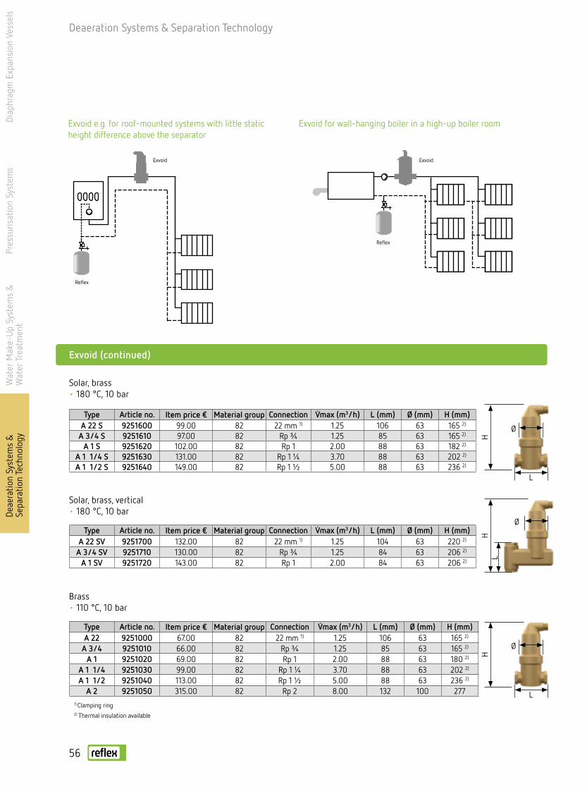
Diap
hrag
m E
xpan
sion
Ves
sels
Pres
suris
atio
n Sy
stem
sW
ater
Mak
e-U
p Sy
stem
s &
W
ater
Tre
atm
ent
Deae
ratio
n Sy
stem
s &
Se
para
tion
Tech
nolo
gy
Exvoid (continued)
Deaeration Systems & Separation Technology
Type Article no. Item price € Material group Connection V̇max (m3/h) L (mm) Ø (mm) H (mm)A 22 S 9251600 99.00 82 22 mm 1) 1.25 106 63 165 2)
A 3/4 S 9251610 97.00 82 Rp ¾ 1.25 85 63 165 2)
A 1 S 9251620 102.00 82 Rp 1 2.00 88 63 182 2)
A 1 1/4 S 9251630 131.00 82 Rp 1 ¼ 3.70 88 63 202 2)
A 1 1/2 S 9251640 149.00 82 Rp 1 ½ 5.00 88 63 236 2)
Type Article no. Item price € Material group Connection V̇max (m3/h) L (mm) Ø (mm) H (mm)A 22 9251000 67.00 82 22 mm 1) 1.25 106 63 165 2)
A 3/4 9251010 66.00 82 Rp ¾ 1.25 85 63 165 2)
A 1 9251020 69.00 82 Rp 1 2.00 88 63 180 2)
A 1 1/4 9251030 99.00 82 Rp 1 ¼ 3.70 88 63 202 2)
A 1 1/2 9251040 113.00 82 Rp 1 ½ 5.00 88 63 236 2)
A 2 9251050 315.00 82 Rp 2 8.00 132 100 277
Type Article no. Item price € Material group Connection V̇max (m3/h) L (mm) Ø (mm) H (mm)A 22 SV 9251700 132.00 82 22 mm 1) 1.25 104 63 220 2)
A 3/4 SV 9251710 130.00 82 Rp ¾ 1.25 84 63 206 2)
A 1 SV 9251720 143.00 82 Rp 1 2.00 84 63 206 2)
Solar, brass• 180 °C, 10 bar
Solar, brass, vertical• 180 °C, 10 bar
Brass• 110 °C, 10 bar
1) Clamping ring 2) Thermal insulation available
Ø
Ø
HH
L
L
Ø
HL
Exvoid e.g. for roof-mounted systems with little static height difference above the separator
Exvoid for wall-hanging boiler in a high-up boiler room
Exvoid
Reflex
Reflex
Exvoid
56

Deaeration Systems & Separation Technology
Exdirt
Deae
ratio
n Sy
stem
s &
Se
para
tion
Tech
nolo
gyDi
aphr
agm
Exp
ansi
on V
esse
lsPr
essu
risat
ion
Syst
ems
Wat
er M
ake-
Up
Syst
ems
&
Wat
er T
reat
men
t
Type Article no. Unit price €
Material group
Connection V̇max (m3/h)
L (mm)
Ø (mm)
H (mm)
HA(mm)
A 50 8251300 796.00 83 DN 50/PN 16 12.5 350 132 629 1) 145A 65 8251310 823.00 83 DN 65/PN 16 20.0 350 132 629 1) 155A 80 8251320 1,127.00 83 DN 80/PN 16 27.0 470 206 743 1) 151A 100 8251330 1,173.00 83 DN 100/PN 16 47.0 475 206 743 1) 161A 125 8251340 2,171.00 83 DN 125/PN 16 72.0 635 354 767 1) 206A 150 8251350 2,254.00 83 DN 150/PN 16 108.0 635 354 767 1) 221A 200 8251360 3,395.00 83 DN 200/PN 16 180.0 775 409 1050 276A 250 8251370 6,886.00 83 DN 250/PN 16 288.0 890 480 1157 338A 300 8251380 12,259.00 83 DN 300/PN 16 405.0 1005 634 1426 393
Steel with flange connection• 110 °C, 10 bar
1) Thermal insulation available
1) Thermal insulation available
Type Article no. Unit price €
Material group
Connection (mm)
V̇max (m3/h)
L (mm)
Ø (mm)
H (mm)
HA(mm)
A 60.3 8251100 612.00 83 60.3 12.5 260 132 629 1) 145A 76.1 8251110 630.00 83 76.1 20.0 260 132 629 1) 155A 88.9 8251120 915.00 83 88.9 27.0 370 206 743 1) 151A 114.3 8251130 943.00 83 114.3 47.0 370 206 743 1) 161A 139.7 8251140 1,909.00 83 139.7 72.0 525 354 767 1) 206A 168.3 8251150 1,964.00 83 168.3 108.0 525 354 767 1) 221A 219.1 8251160 3,082.00 83 219.1 180.0 650 409 1050 276A 273.0 8251170 6,210.00 83 273.0 288.0 750 480 1157 338A 323.9 8251180 11,546.00 83 323.9 405.0 850 634 1426 393
Steel with welded connection• 110 °C, 10 bar
Exvoid (continued)
Type Article no. Item price € Material group Connection V̇max (m3/h) L (mm) Ø (mm) H (mm)A 22 V 9251500 96.00 82 22 mm 1) 1.25 84 63 206 2)
A 3/4 V 9251510 95.00 82 Rp ¾ 1.25 84 63 206 2)
A 1 V 9251520 98.00 82 Rp 1 1.25 84 63 206 2)
Brass, vertical• 110 °C, 10 bar
1) Clamping ring 2) Thermal insulation available
Special versions for increased volume flows on request
Ø
HL
Ø
Ø
L
L
H
HAHA
H
min. 50 mm
min. 50 mm
57

Deaeration Systems & Separation Technology
Exdirt
Type Article no. Item price € Material group Connection V̇max (m3/h) L (mm) Ø (mm) H (mm)D 22 9252000 67.00 82 22 mm 1) 1.25 85 63 103 2)
D 3/4 9252010 66.00 82 Rp ¾ 1.25 85 63 103 2)
D 1 9252020 69.00 82 Rp 1 2.00 88 63 120 2)
D 1 1/4 9252030 99.00 82 Rp 1 ¼ 3.70 88 63 140 2)
D 1 1/2 9252040 113.00 82 Rp 1 ½ 5.00 88 63 174 2)
D 2 9252050 315.00 82 Rp 2 8.00 132 100 215
Brass• 110 °C, 10 bar
1) Clamping ring 2)Thermal insulation available
Exdirt
Ø
H
L
Dirt and sludge separator• Removes free-circulating dirt and sludge particles• Functions in fully automated, continuous operation• Only produces a minimal, constant drop in pressure• Maintenance takes just 5 seconds• Permanent free throughflow opening for the water• No shut-off valves or bypass lines required• Desludging possible during system operation• Full range in terms of operating pressures, temperatures and materials• Continually ensures flawless functionality of heat generators, thermostat valves, etc.• Reduces the risk of defects and breakdowns in the long term
Diap
hrag
m E
xpan
sion
Ves
sels
Pres
suris
atio
n Sy
stem
sW
ater
Mak
e-U
p Sy
stem
s &
W
ater
Tre
atm
ent
Deae
ratio
n Sy
stem
s &
Se
para
tion
Tech
nolo
gy
Exdirt for protecting the heat generator from sludge build-up in a multi-boiler system
Exdirt in the supply to sensitive consumers, e.g. fan con-vectors, fine-tune valves, etc.
Exdirt
ReflexReflex
Reflex
Exdirt
Exdirt
Exdirt for protecting the heat generator from sludge build-up in a multi-boiler system
Exdirt
58
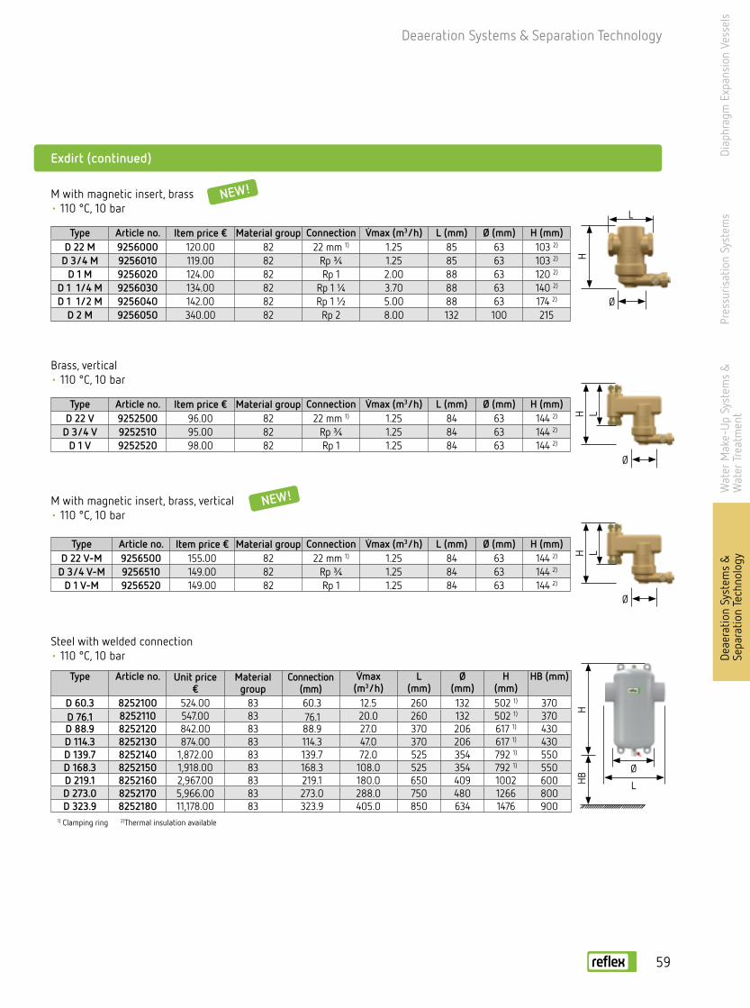
Deaeration Systems & Separation Technology
Exdirt (continued)
Type Article no. Item price € Material group Connection V̇max (m3/h) L (mm) Ø (mm) H (mm)D 22 V 9252500 96.00 82 22 mm 1) 1.25 84 63 144 2)
D 3/4 V 9252510 95.00 82 Rp ¾ 1.25 84 63 144 2)
D 1 V 9252520 98.00 82 Rp 1 1.25 84 63 144 2)
Brass, vertical• 110 °C, 10 bar
Type Article no. Item price € Material group Connection V̇max (m3/h) L (mm) Ø (mm) H (mm)D 22 M 9256000 120.00 82 22 mm 1) 1.25 85 63 103 2)
D 3/4 M 9256010 119.00 82 Rp ¾ 1.25 85 63 103 2)
D 1 M 9256020 124.00 82 Rp 1 2.00 88 63 120 2)
D 1 1/4 M 9256030 134.00 82 Rp 1 ¼ 3.70 88 63 140 2)
D 1 1/2 M 9256040 142.00 82 Rp 1 ½ 5.00 88 63 174 2)
D 2 M 9256050 340.00 82 Rp 2 8.00 132 100 215
M with magnetic insert, brass• 110 °C, 10 bar
Type Article no. Item price € Material group Connection V̇max (m3/h) L (mm) Ø (mm) H (mm)D 22 V-M 9256500 155.00 82 22 mm 1) 1.25 84 63 144 2)
D 3/4 V-M 9256510 149.00 82 Rp ¾ 1.25 84 63 144 2)
D 1 V-M 9256520 149.00 82 Rp 1 1.25 84 63 144 2)
Type Article no. Unit price €
Material group
Connection (mm)
V̇max (m3/h)
L (mm)
Ø (mm)
H (mm)
HB (mm)
D 60.3 8252100 524.00 83 60.3 12.5 260 132 502 1) 370D 76.1 8252110 547.00 83 76.1 20.0 260 132 502 1) 370D 88.9 8252120 842.00 83 88.9 27.0 370 206 617 1) 430D 114.3 8252130 874.00 83 114.3 47.0 370 206 617 1) 430D 139.7 8252140 1,872.00 83 139.7 72.0 525 354 792 1) 550D 168.3 8252150 1,918.00 83 168.3 108.0 525 354 792 1) 550D 219.1 8252160 2,967.00 83 219.1 180.0 650 409 1002 600D 273.0 8252170 5,966.00 83 273.0 288.0 750 480 1266 800D 323.9 8252180 11,178.00 83 323.9 405.0 850 634 1476 900
Steel with welded connection• 110 °C, 10 bar
M with magnetic insert, brass, vertical• 110 °C, 10 bar
1) Clamping ring 2)Thermal insulation available
Ø
H
L
Ø
L
H
Ø
H LØ
H LHB
NEW!
NEW!
Deae
ratio
n Sy
stem
s &
Se
para
tion
Tech
nolo
gyDi
aphr
agm
Exp
ansi
on V
esse
lsPr
essu
risat
ion
Syst
ems
Wat
er M
ake-
Up
Syst
ems
&
Wat
er T
reat
men
t
59
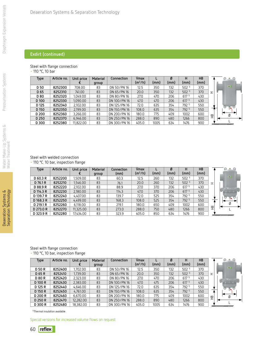
Deaeration Systems & Separation Technology
Diap
hrag
m E
xpan
sion
Ves
sels
Pres
suris
atio
n Sy
stem
sW
ater
Mak
e-U
p Sy
stem
s &
W
ater
Tre
atm
ent
Deae
ratio
n Sy
stem
s &
Se
para
tion
Tech
nolo
gy
Type Article no. Unit price €
Material group
Connection (mm)
V̇max (m3/h)
L (mm)
Ø (mm)
H (mm)
HB(mm)
D 60.3 R 8252200 1,509.00 83 60.3 12.5 260 132 502 1) 370D 76.1 R 8252210 1,546.00 83 76.1 20.0 260 132 502 1) 370D 88.9 R 8252220 2,102.00 83 88.9 27.0 370 206 617 1) 430D 114.3 R 8252230 2,180.00 83 114.3 47.0 370 206 617 1) 430D 139.7 R 8252240 4,407.00 83 139.7 72.0 525 354 792 1) 550D 168.3 R 8252250 4,499.00 83 168.3 108.0 525 354 792 1) 550D 219.1 R 8252260 6,118.00 83 219.1 180.0 650 409 1002 600D 273.0 R 8252270 11,325.00 83 273.0 288.0 750 480 1266 800D 323.9 R 8252280 17,434.00 83 323.9 405.0 850 634 1476 900
Steel with welded connection• 110 °C, 10 bar, inspection flange
Exdirt (continued)
Steel with flange connection• 110 °C, 10 bar
Type Article no. Unit price €
Material group
Connection V̇max (m3/h)
L (mm)
Ø (mm)
H (mm)
HB(mm)
D 50 8252300 708.00 83 DN 50/PN 16 12.5 350 132 502 1) 370D 65 8252310 741.00 83 DN 65/PN 16 20.0 350 132 502 1) 370D 80 8252320 1,049.00 83 DN 80/PN 16 27.0 470 206 617 1) 430D 100 8252330 1,090.00 83 DN 100/PN 16 47.0 470 206 617 1) 430D 125 8252340 2,102.00 83 DN 125/PN 16 72.0 635 354 792 1) 550D 150 8252350 2,199.00 83 DN 150/PN 16 108.0 635 354 792 1) 550D 200 8252360 3,266.00 83 DN 200/PN 16 180.0 775 409 1002 600D 250 8252370 6,946.00 83 DN 250/PN 16 288.0 890 480 1266 800D 300 8252380 11,822.00 83 DN 300/PN 16 405.0 1005 634 1476 900
Type Article no. Unit price €
Material group
Connection V̇max (m3/h)
L (mm)
Ø (mm)
H (mm)
HB(mm)
D 50 R 8252400 1,702.00 83 DN 50/PN 16 12.5 350 132 502 1) 370D 65 R 8252410 1,739.00 83 DN 65/PN 16 20.0 350 132 502 1) 370D 80 R 8252420 2,323.00 83 DN 80/PN 16 27.0 470 206 617 1) 430D 100 R 8252430 2,383.00 83 DN 100/PN 16 47.0 475 206 617 1) 430D 125 R 8252440 4,646.00 83 DN 125/PN 16 72.0 635 354 792 1) 550D 150 R 8252450 4,761.00 83 DN 150/PN 16 108.0 635 354 792 1) 550D 200 R 8252460 6,670.00 83 DN 200/PN 16 180.0 775 409 1002 600D 250 R 8252470 12,282.00 83 DN 250/PN 16 288.0 890 480 1266 800D 300 R 8252480 18,382.00 83 DN 300/PN 16 405.0 1005 634 1476 900
Steel with flange connection• 110 °C, 10 bar, inspection flange
1) Thermal insulation available
Special versions for increased volume flows on request
Ø
LH
Ø
Ø
L
L
HH
HBHB
HB
60
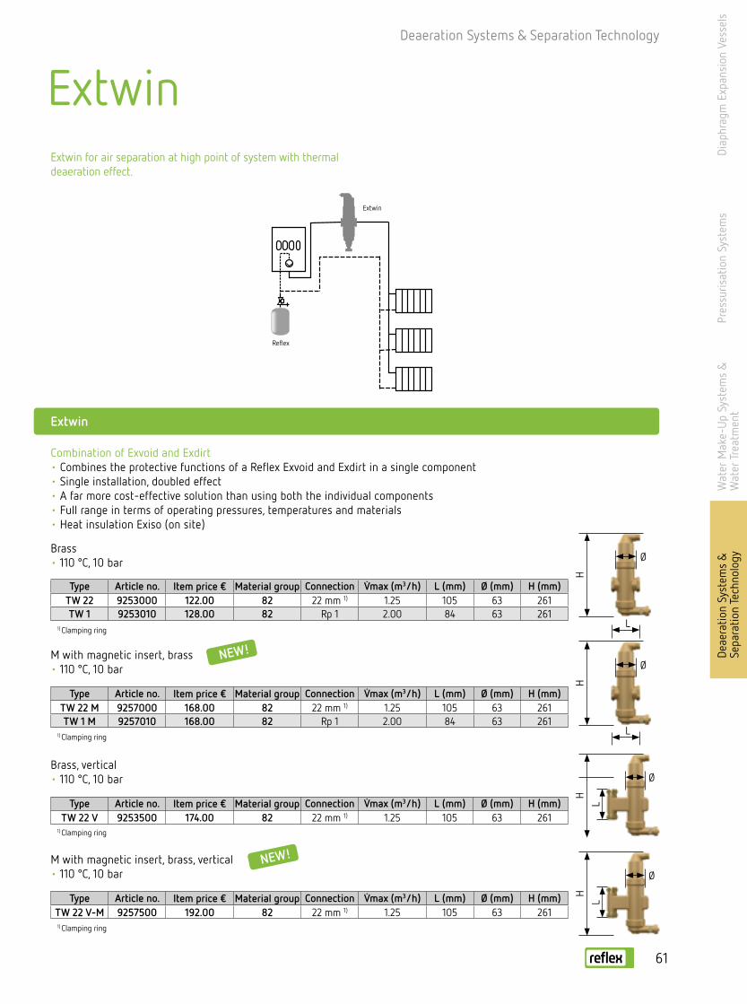
Deaeration Systems & Separation Technology
Type Article no. Item price € Material group Connection V̇max (m3/h) L (mm) Ø (mm) H (mm)TW 22 M 9257000 168.00 82 22 mm 1) 1.25 105 63 261TW 1 M 9257010 168.00 82 Rp 1 2.00 84 63 261
M with magnetic insert, brass• 110 °C, 10 bar
Extwin
Type Article no. Item price € Material group Connection V̇max (m3/h) L (mm) Ø (mm) H (mm)TW 22 9253000 122.00 82 22 mm 1) 1.25 105 63 261TW 1 9253010 128.00 82 Rp 1 2.00 84 63 261
Brass• 110 °C, 10 bar
1) Clamping ring
Extwin
Ø
Ø
HH
L
L
Combination of Exvoid and Exdirt • Combines the protective functions of a Reflex Exvoid and Exdirt in a single component• Single installation, doubled effect• A far more cost-effective solution than using both the individual components• Full range in terms of operating pressures, temperatures and materials• Heat insulation Exiso (on site)
NEW!
Diap
hrag
m E
xpan
sion
Ves
sels
Pres
suris
atio
n Sy
stem
sW
ater
Mak
e-U
p Sy
stem
s &
W
ater
Tre
atm
ent
Deae
ratio
n Sy
stem
s &
Se
para
tion
Tech
nolo
gy
Brass, vertical• 110 °C, 10 bar
1) Clamping ringType Article no. Item price € Material group Connection V̇max (m3/h) L (mm) Ø (mm) H (mm)
TW 22 V 9253500 174.00 82 22 mm 1) 1.25 105 63 261
1) Clamping ring
1) Clamping ring
Ø
H
L
M with magnetic insert, brass, vertical• 110 °C, 10 bar
Type Article no. Item price € Material group Connection V̇max (m3/h) L (mm) Ø (mm) H (mm)TW 22 V-M 9257500 192.00 82 22 mm 1) 1.25 105 63 2611) Clamping ring
Ø
H
L
NEW!
Extwin for air separation at high point of system with thermal deaeration effect.
Extwin
Reflex
61

Deaeration Systems & Separation Technology
Diap
hrag
m E
xpan
sion
Ves
sels
Pres
suris
atio
n Sy
stem
sW
ater
Mak
e-U
p Sy
stem
s &
W
ater
Tre
atm
ent
Deae
ratio
n Sy
stem
s &
Se
para
tion
Tech
nolo
gy
Type Article no. Unit price €
Material group
Connection (mm) V̇max (m3/h)
L (mm)
Ø (mm)
H (mm)
HB (mm)
TW 60.3 R 8253200 1,748.00 83 60.3 12.5 350 132 770 370TW 76.1 R 8253210 1,794.00 83 76.1 20.0 350 132 770 370TW 88.9 R 8253220 2,415.00 83 88.9 27.0 470 206 925 430TW 114.3 R 8253230 2,461.00 83 114.3 47.0 475 206 925 430TW 139.7 R 8253240 4,876.00 83 139.7 72.0 635 354 1185 550TW 168.3 R 8253250 4,968.00 83 168.3 108.0 635 354 1185 550TW 219.1 R 8253260 6,808.00 83 219.1 180.0 775 409 1455 600TW 273.0 R 8253270 12,834.00 83 273.0 288.0 890 480 1855 800TW 323.9 R 8253280 22,540.00 83 323.9 405.0 1005 634 2175 900
Steel with welded connection• 110 °C, 10 bar, inspection flange
Steel with flange connection• 110 °C, 10 bar
Type Article no. Unit price €
Material group
Connection V̇max (m3/h)
L (mm)
Ø (mm)
H (mm)
HB (mm)
TW 50 8253300 966.00 83 DN 50/PN 16 12.5 350 132 770 370TW 65 8253310 1,012.00 83 DN 65/PN 16 20.0 350 132 770 370TW 80 8253320 1,329.00 83 DN 80/PN 16 27.0 470 206 925 430TW 100 8253330 1,389.00 83 DN 100/PN 16 47.0 475 206 925 430TW 125 8253340 2,461.00 83 DN 125/PN 16 72.0 635 354 1185 550TW 150 8253350 2,553.00 83 DN 150/PN 16 108.0 635 354 1185 550TW 200 8253360 4,370.00 83 DN 200/PN 16 180.0 775 409 1455 600TW 250 8253370 9,154.00 83 DN 250/PN 16 288.0 890 480 1855 800TW 300 8253380 15,962.00 83 DN 300/PN 16 405.0 1005 634 2175 900
Extwin (continued)
Steel with flange connection• 110 °C, 10 bar, inspection flange
Type Article no. Unit price €
Material group
Connection V̇max (m3/h)
L (mm)
Ø (mm)
H (mm)
HB (mm)
TW 50 R 8253400 1,946.00 83 DN 50/PN 16 12.5 350 132 770 370TW 65 R 8253410 2,006.00 83 DN 65/PN 16 20.0 350 132 770 370TW 80 R 8253420 2,631.00 83 DN 80/PN 16 27.0 470 206 925 430TW 100 R 8253430 2,714.00 83 DN 100/PN 16 47.0 475 206 925 430TW 125 R 8253440 5,152.00 83 DN 125/PN 16 72.0 635 354 1185 550TW 150 R 8253450 5,290.00 83 DN 150/PN 16 108.0 635 354 1185 550TW 200 R 8253460 7,590.00 83 DN 200/PN 16 180.0 775 409 1455 600TW 250 R 8253470 13,892.00 83 DN 250/PN 16 288.0 890 480 1855 800TW 300 R 8253480 23,092.00 83 DN 300/PN 16 405.0 1005 634 2175 900
min. 50 mm
Ø
L
H
min. 50 mm
Ø
L
H
min. 50 mm
Ø
L
HHB
HBHB
Type Article no. Unit price €
Material group
Connection (mm)
V̇max (m3/h)
L (mm)
Ø (mm)
H (mm)
HB(mm)
TW 60.3 8253100 777.00 83 60.3 12.5 260 132 770 370TW 76.1 8253110 814.00 83 76.1 20.0 260 132 770 370TW 88.9 8253120 1,113.00 83 88.9 27.0 370 206 925 430TW 114.3 8253130 1,150.00 83 114.3 47.0 370 206 925 430TW 139.7 8253140 2,194.00 83 139.7 72.0 525 354 1185 550TW 168.3 8253150 2,254.00 83 168.3 108.0 525 354 1185 550TW 219.1 8253160 3,910.00 83 219.1 180.0 650 409 1455 600TW 273.0 8253170 8,809.00 83 273.0 288.0 750 480 1855 800TW 323.9 8253180 15,180.00 83 323.9 405.0 850 634 2175 900
Steel with welded connection• 110 °C, 10 bar
min. 50 mm
Ø
L
HHB
62

6 ba
r10
bar
Type Article no. Item price € Material groupInsulation thick-
ness (mm) Ø (mm) H (mm)
A/D 22 1 ½ 9254811 22.00 82 15 125 215-275
Type Article no. Item price € Material groupInsulation thick-
ness (mm) Ø (mm) H (mm)
50-76.1 9254831 132.00 83 30.5 228 44780-114.1 9254841 164.00 83 30.5 290 567
125-168.3 9254851 264.00 83 30.5 395 742
Type Article no. Item price € Area of application Installation length (mm)D 50/140.3 9258300 385.00 DN 50 – DN 100 300D 125/219.1 9258310 435.00 DN 125 – DN 200 350D 250/323.9 9258320 530.00 DN 250 – DN 300 400D 350/600 9258330 630.00 > DN 100 500
Exiso
Thermal insulation for Exvoid type A 22 A1½ and Exdirt D 22-D1½
• Solenoid insert for sludge separator• 110 °C/10 bar• Magnetic bar screwed into thermowell/T-piece• For uptake of ferromagnetic substances
Thermal insulation for Exvoid and Exdirt, steel version
Deaeration Systems & Separation Technology
Exferro
Accessories
Dirt collectors
Type10 bar/120 °C
Article no. Unit price €
Material group Ø D mm
H mm
hmm
A1 A2
EB 30 8636000 228.00 25 409 455 270 R 1 ¼ R 1EB 60 8635100 327.00 25 409 770 465 DN 50/PN 16 R 1EB 80 8636200 423.00 25 480 765 468 DN 65/PN 16 R 1EB 100 8636300 593.00 25 480 870 535 DN 80/PN 16 R 1
6 bar/120 °CEB 180 8632000 1,178.00 25 600 1110 726 DN 100/PN 6 R 1EB 300 8633000 1,461.00 25 600 1600 1141 DN 125/PN 6 R 1EB 400 8634000 1,972.00 25 750 1500 1027 DN 150/PN 6 R 1EB 750 8634100 2,543.00 25 750 2215 1677 DN 250/PN 6 R 1
• For installation in liquid circuits for sedimentation of fine sludge and suspended matter
• Coated grey
60–750 litres
H
A1
A2
A1Ø D
30 litres
Ø D
H
A1
A1
A2
h hDi
aphr
agm
Exp
ansi
on V
esse
lsPr
essu
risat
ion
Syst
ems
Wat
er M
ake-
Up
Syst
ems
&
Wat
er T
reat
men
tDe
aera
tion
Syst
ems
&
Sepa
ratio
n Te
chno
logy
63

Diap
hrag
m E
xpan
sion
Ves
sels
Pres
suris
atio
n Sy
stem
sW
ater
Mak
e-U
p Sy
stem
s &
W
ater
Tre
atm
ent
Deaeration Systems & Separation Technology
Deae
ratio
n Sy
stem
s &
Se
para
tion
Tech
nolo
gy
10 b
ar
Air separators
Type10 bar/120 °C
Article no. Unit price €
Material group L mm
h mm
Ø D mm
A
LA 32 8671000 83.90 72 300 30 206 DN 32LA 40 8672000 88.30 72 300 40 206 DN 40LA 50 8673000 117.00 72 300 40 206 DN 50LA 65 8674000 146.00 72 390 60 280 DN 65LA 80 8675000 153.00 72 390 60 280 DN 80LA 100 8676000 336.00 72 390 50 280 DN 100LA 125 8677000 363.00 72 390 40 280 DN 125LA 150 8678000 437.00 72 590 90 409 DN 150LA 200 8679000 613.00 72 590 40 409 DN 200
• For separating gas bubbles in fluid circuits, particularly at low static pressures• With welded connection
DE
Coupling Rp 3/8
L
DE
L
LA 32 – LA 50 LA 65 – LA 200
W
hA
B
h
Coupling Rp 3/8
A
Expansion traps
Type Article no. Unit price €
Material group H mm
h mm
Ø Dmm
A 1DN
A 2DN
A 3 DN
T 170 8680000 75.70 73 328 55 206 50 65 65T 270 8681000 108.00 73 400 65 280 65 80 80T 380 8682000 177.00 73 528 75 490 80 100 100T 480 8683000 219.00 73 710 115 480 125 150 150T 550 8684000 369.00 73 896 125 634 150 200 200
• For connection to safety valves of heat generators for separating water-steam mixtures in accordance with DIN EN 12828
• Coated grey • Max. operating temperature 120 °C
A 2
Ø D
A 1hH
A 3
64
Diap
hrag
m E
xpan
sion
Ves
sels
Pres
suris
atio
n Sy
stem
sW
ater
Mak
e-U
p Sy
stem
s &
W
ater
Tre
atm
ent
Deae
ratio
n Sy
stem
s &
Se
para
tion
Tech
nolo
gyH
ot W
ater
Sto
rage
Tank
s &
H
eat
Exch
ange
rs
Hot Water Storage Tanks & Heat Exchangers

Storatherm Heat buffer storage tank
• Storage tank made of high-grade steel S235JRG2 (RSt 37-2)• Up to 2000 litres incl. removable 90 mm PU flexible foam insulation with white or
silver foil cladding• For cooling water systems, Storatherm buffer storage tanks are also available without
foam insulation (type "H"); in this case, appropriate diffusion-resistant insulation must be provided on-site
• Untreated on the inside, with an outer plastic coating• Perm. excess operating pressure for storage tank 3 bar (6 bar above 1500 litres)• Perm. excess operating pressure for heat exchanger 16 bar• Perm. operating temperature for storage tank 95 °C • Perm. operating temperature for heat exchanger 110 °C• Storatherm Heat HF .... and H ....: basic buffer storage tank• Storatherm Heat HF .... /R and H .... /R: with additional cleaning and inspection
aperture, LK 150 mm• Storatherm Heat HF .... /1 and HF .... /1: with a smooth tube heat exchanger for
connecting an additional heat source• Storatherm Heat HF .... /2 and HF .... /2: with two smooth tube heat exchangers for
connecting two additional heat sources• Type HF: Buffer storage tank with thermal insulation, insulated• Type H: Buffer storage tank without thermal insulation for cold water systems;
insulation for heating water systems for 3000 l, 4000 l and 5000 l sizes is available separately (see page 68)
Storage tank type
Article no. White Silver
Unit price€
Material group
Ø Dmm
Height Hmm
Couplings9 x
Tipping dimension 2)
mm
Weightkg
HF 2001) 8500000 8502000 590.00 63 660 1) 1500 Rp 1 ½ 1525 51.01)
HF 3001) 8500010 8502010 656.00 63 777 1) 1320 Rp 1 ½ 1355 59.0 1)
HF 5001) 8500020 8502020 759.00 63 777 1) 1950 Rp 1 ½ 1974 72.0 1)
HF 8001) 8500030 8502030 1,102.00 63 970 1) 1825 Rp 1 ½ 1870 124.0 1)
HF 10001) 8500040 8502040 1,324.00 63 970 1) 2115 Rp 1 ½ 2153 139.0 1)
HF 15001) 8500050 8502050 1,929.00 63 1180 1) 2120 Rp 1 ½ 2178 186.0 1)
HF 20001) 8500060 8502060 2,649.00 63 1380 1) 2122 Rp 1 ½ 2200 266.0 1)
H 2002) 7788000 385.00 63 480 2) 1500 Rp 1 ½ 1525 47.0 2)
H 3002) 7783000 415.00 63 597 2) 1320 Rp 1 ½ 1355 55.0 2)
H 5002) 7783100 469.00 63 597 2) 1950 Rp 1 ½ 1975 66.0 2)
H 8002) 7783225 723.00 63 790 2) 1825 Rp 1 ½ 1870 116.0 2)
H 10002) 7783333 892.00 63 790 2) 2115 Rp 1 ½ 2153 131.0 2)
H 15002) 7783400 1,387.00 63 1000 2) 2120 Rp 1 ½ 2178 178.0 2)
H 20002) 7783500 2,024.00 63 1200 2) 2122 Rp 1 ½ 2200 257.0 2)
H 30002) 7788100 3,209.00 63 1500 2) 2101 Rp 2 2205 567.0 2)
H 40002) 7788400 3,909.00 63 1500 2) 2676 Rp 2 2756 674.0 2)
H 50002) 7788700 4,809.00 63 1500 2) 3211 Rp 2 3264 811.0 2)
Hot Water Storage Tanks & Heat Exchangers
1) Incl. thermal insulation 2) Without thermal insulation
Storatherm Heat buffer storage tank without smooth tube heat exchanger or inspection flange
Storatherm Heat
Ø D
H
Diap
hrag
m E
xpan
sion
Ves
sels
Pres
suris
atio
n Sy
stem
sW
ater
Mak
e-U
p Sy
stem
s &
W
ater
Tre
atm
ent
Deae
ratio
n Sy
stem
s &
Se
para
tion
Tech
nolo
gyH
ot W
ater
Sto
rage
Tank
s &
H
eat
Exch
ange
rs
66

Hot Water Storage Tanks & Heat Exchangers
Storatherm Heat buffer storage tanks for heating systems (continued)
Storage tank type
Article no. White Silver
Unit price€
Material group
Ø Dmm
Height Hmm
Couplings9 x
Tipping dimension 2)
mm
Weightkg
HF 300/R1) 8500070 8502070 698.00 63 777 1) 1320 Rp 1 ½ 1355 62.0 1)
HF 500/R1) 8500080 8502080 798.00 63 777 1) 1950 Rp 1 ½ 1974 75.0 1)
HF 800/R1) 8500090 8502090 1,150.00 63 970 1) 1825 Rp 1 ½ 1870 127.0 1)
HF 1000/R1) 8500100 8502100 1,372.00 63 970 1) 2115 Rp 1 ½ 2153 142.0 1)
HF 1500/R1) 8500200 8502200 2,010.00 63 1180 1) 2120 Rp 1 ½ 2178 189.0 1)
HF 2000/R1) 8500300 8502300 2,693.00 63 1380 1) 2122 Rp 1 ½ 2200 269.0 1)
H 300/R2) 7783600 440.00 63 597 2) 1320 Rp 1 ½ 1355 58.0 1)
H 500/R2) 7783800 493.00 63 597 2) 1950 Rp 1 ½ 1974 71.0 1)
H 800/R2) 7784005 756.00 63 790 2) 1825 Rp 1 ½ 1870 121.0 1)
H 1000/R2) 7784205 925.00 63 790 2) 2115 Rp 1 ½ 2153 135.0 1)
H 1500/R2) 7784400 1,449.00 63 1000 2) 2120 Rp 1 ½ 2178 181.0 1)
H 2000/R2) 7784600 2,052.00 63 1200 2) 2122 Rp 1 ½ 2200 257.0 1)
H 3000/R2) 7788200 3,269.00 63 1500 2) 2101 Rp 2 2205 570.0 1)
H 4000/R2) 7788500 3,996.00 63 1500 2) 2676 Rp 2 2756 677.0 1)
H 5000/R2) 7788800 4,996.00 63 1500 2) 3211 Rp 2 3264 814.0 1)
1) Incl. thermal insulation 2) Without thermal insulation
The EFHR screw-in heater and RWT1 ribbed-tube heat exchanger may be installed
Storatherm Heat buffer storage tank without smooth tube heat exchanger, with inspection flange, LK 150
Storatherm Heat buffer storage tank with one smooth tube heat exchanger
Storage tank type
Article no. White Silver
Unit price€
Material group
Ø Dmm
Height Hmm
Couplings9 x
Tipping dimension 2)
mm
Weightkg
Heating surface
m2
HF 300/11) 8500400 8502400 781.00 63 777 1) 1320 Rp 1 ½ 1355 82.0 1) 1.34HF 500/11) 8500500 8502500 907.00 63 777 1) 1950 Rp 1 ½ 1974 100.0 1) 1.88HF 800/11) 8500600 8502600 1,376.00 63 970 1) 1825 Rp 1 ½ 1870 197.0 1) 3.76HF 1000/11) 8500700 8502700 1,606.00 63 970 1) 2115 Rp 1 ½ 2153 225.0 1) 4.48HF 1500/11) 8500800 8502800 2,309.00 63 1180 1) 2120 Rp 1 ½ 2178 272.0 1) 4.48HF 2000/11) 8500900 8502900 2,996.00 63 1380 1) 2122 Rp 1 ½ 2200 352.0 1) 4.48
H 300/12) 7783700 541.00 63 597 2) 1320 Rp 1 ½ 1335 74.0 2) 1.34H 500/12) 7783900 619.00 63 597 2) 1950 Rp 1 ½ 1974 95.0 2) 1.88H 800/12) 7784115 989.00 63 790 2) 1925 Rp 1 ½ 1870 190.0 2) 3.76H 1000/12) 7784315 1,170.00 63 790 2) 2115 Rp 1 ½ 2153 216.0 2) 4.48H 1500/12) 7784500 1.75800 63 1000 2) 2120 Rp 1 ½ 2178 265.0 2) 4.48H 2000/12) 7784700 2,365.00 63 1200 2) 2122 Rp 1 ½ 2200 341.0 2) 4.48 H 3000/12) 7788300 3,540.00 63 1500 2) 2101 Rp 2 2205 637.0 2) 5.00H 4000/12) 7788600 4,540.00 63 1500 2) 2676 Rp 2 2756 754.0 2) 6.00H 5000/12) 7788900 5,340.00 63 1500 2) 3211 Rp 2 3264 871.0 2) 7.00
1) Incl. thermal insulation 2) Without thermal insulation
Diap
hrag
m E
xpan
sion
Ves
sels
Pres
suris
atio
n Sy
stem
sW
ater
Mak
e-U
p Sy
stem
s &
W
ater
Tre
atm
ent
Deae
ratio
n Sy
stem
s &
Se
para
tion
Tech
nolo
gyH
ot W
ater
Sto
rage
Tank
s &
H
eat
Exch
ange
rs
67

Hot Water Storage Tanks & Heat Exchangers
Reflex HWF foil cladding
Thermal insulation for Storatherm Heat buffer storage tanks with 3000, 4000 and 5000 litre volumes
Type Article no. Blue Silver Orange
Unit price€
Material group
HWF 200 9119330 9119340 9119320 43.10 64HWF 300 9119331 9199341 9119321 52.60 64HWF 500 9119332 9119342 9119322 67.20 64HWF 800 9119484 9119485 9119483 99.60 64HWF 1000 9119488 9119489 9119487 114.00 64HWF 1500 9119335 9119345 9119325 129.00 64HWF 2000 9119336 9119346 9119326 149.00 64
• Additional coloured foil cladding for Reflex buffer storage tank
Diap
hrag
m E
xpan
sion
Ves
sels
Pres
suris
atio
n Sy
stem
sW
ater
Mak
e-U
p Sy
stem
s &
W
ater
Tre
atm
ent
Deae
ratio
n Sy
stem
s &
Se
para
tion
Tech
nolo
gy
• Made of 90 mm thick PU flexible foam with a white, laminated foil cladding
• Removable, for assembly on site
Type Article no. White Orange Blue Silver
Unit price €
Material group
HW 3000 9119307 9119327 9119337 9119347 716.00 64HW 4000 9119308 9119328 9119338 9119348 845.00 64HW 5000 9119309 9119329 9119339 9119349 1,040.00 64
Storatherm Heat buffer storage tanks for heating systems (continued)
Storatherm Heat buffer storage tank with two smooth tube heat exchangers
Storage tank type
Article no. White Silver
Unit price€
Material group
Ø Dmm
Height Hmm
Couplings9 x
Tipping dimension 2)
mm
Weightkg
Heating sur-face
top/bottom, m2
HF 500/21) 8500513 8500510 1,025.00 63 777 1) 1950 Rp 1 ½ 1974 125 1) 1.17/1.88HF 800/21) 8500613 8500610 1,473.00 63 970 1) 1825 Rp 1 ½ 1870 267 1) 1.86/2.47HF 1000/21) 8500713 8500710 1,761.00 63 970 1) 2115 Rp 1 ½ 2153 308 1) 2.47/3.10HF 1500/21) 8500813 8500810 2,513.00 63 1180 1) 2120 Rp 1 ½ 2178 355 1) 2.37/3.72HF 2000/21) 8500913 8500910 3,224.00 63 1380 1) 2122 Rp 1 ½ 2200 438 1) 2.05 /3.72
H 500/22) 7787900 on req. 63 597 2) 1950 Rp 1 ½ 1974 118 2) 1.17/1.88H 800/22) 7787910 on req. 63 790 2) 1825 Rp 1 ½ 1870 259 2) 1.86/2.47H 1000/22) 7787920 on req. 63 790 2) 2115 Rp 1 ½ 2153 279 2) 2.47/3.1H 1500/22) 7787930 on req. 63 100 2) 2120 Rp 1 ½ 2178 346 2) 2.37/3.72H 2000/22) 7787940 on req. 63 120 2) 2122 Rp 1 ½ 2200 425 2) 2.05/3.72
1) Incl. thermal insulation 2) Without thermal insulation
Hot
Wat
er S
tora
ge Ta
nks
&
Hea
t Ex
chan
gers
68

Hot Water Storage Tanks & Heat Exchangers
Storatherm Heat Combi
Type Article no. Unit price€
Material group
Tank sizelitres
OutputkW
VoltageV
Installation length
mm
Bmm
Hmm
DEmm
EFHR 4.0 9116314 534.00 68 150 – 5000 4.0/2.7/2.0 400 295 150 110 185EFHR 6.0 9116315 602.00 68 300 – 5000 6.0/4.0/3.0 400 395 150 110 185EFHR 8.0 9116316 614.00 68 300 – 5000 8.0/5.5/4.0 400 495 150 110 185EFHR 10.0 9116317 720.00 68 300 – 5000 10.0/6.7/5.0 400 495 150 110 185
Thermal insulation for Storatherm Heat buffer storage tanks with 3000, 4000 and 5000 litre volumes
Reflex EFHR electrical screw-in heater
• Hygienic storage tank for heating hot water and back-up for heating systems• Storage tank made of high-grade steel S235JRG2 (RSt 37-2)• Hot water heating in a large-volume corrugated stainless steel pipe • Heat infeed using one (HC ..../1) or two (HC ..../2) smooth tube heat exchangers• With coupling 1 ½" for the optional installation of supplementary electric heating• Incl. 120 mm polyester fleece insulation with a silver PS outer cladding• Untreated on the inside, with an outer plastic coating • Heating surfaces: Max. 10 bar/110 °C• Storage tank: Max. 3 bar/95 °C• Potable water: 6 bar/95 °C
Storage tank type
Article no. Unit price€
Material group
Volume of hot water corrugated
pipe l
Ø D1)
mmHeight
mmWeight
kgTipping
dimension 2)
mm
Heating surfacetop/bottom m2
HC 500/1 8601000 2,390.00 63 27 840 1970 92 1974 1.60HC 800/1 8601010 2,780.00 63 37 1030 1850 131 1870 2.60HC 1000/1 8601020 3,245.00 63 47 1030 2140 152 2153 2.60HC 1500/1 8601030 4,225.00 63 52 1240 2130 219 2178 2.15
HC 500/2 8601050 2,505.00 63 27 840 1970 106 1974 1.14/1.60HC 800/2 8601060 2,982.00 63 37 1030 1850 152 1870 1.75/2.60HC 1000/2 8601070 3,410.00 63 47 1030 2140 179 2153 2.2/2.6HC 1500/2 8601080 4,470.00 63 52 1240 2130 237 2178 1.50/2.15
1) Incl. thermal insulation 2) Without thermal insulation
• As supplementary electrical heating• Approved for continuous operation• Suitable for types: Storatherm Heat HF ..../R Storatherm Heat H ..../R• For integration via the inspection opening of the storage tank• Pitch circle 150 mm• 3 power levels, switchable• With temperature control up to 95 °C• Safety temperature limiter 120 °C• On-site electrical connection• Incl. flange and seal
Installation length
HDE
B
Diap
hrag
m E
xpan
sion
Ves
sels
Pres
suris
atio
n Sy
stem
sW
ater
Mak
e-U
p Sy
stem
s &
W
ater
Tre
atm
ent
Deae
ratio
n Sy
stem
s &
Se
para
tion
Tech
nolo
gy
HC ..../1 HC ..../2
Hot
Wat
er S
tora
ge Ta
nks
&
Hea
t Ex
chan
gers
69

Hot Water Storage Tanks & Heat Exchangers
Diap
hrag
m E
xpan
sion
Ves
sels
Pres
suris
atio
n Sy
stem
sW
ater
Mak
e-U
p Sy
stem
s &
W
ater
Tre
atm
ent
Deae
ratio
n Sy
stem
s &
Se
para
tion
Tech
nolo
gy
Reflex EEHR electric screw-in heater 1 ½"
Heating time information for electrical back-up heating
Type Article no. Unit price€
Material group Tank sizelitres
OutputkW
VoltageV
Installation lengthmm
EEHR 3.0 7755100 375.00 68 > 100 3.00 230 375EEHR 4.5 7755300 435.00 68 > 300 4.50 400 450EEHR 6.0 7755400 459.00 68 > 300 6.00 400 510EEHR 8.0 7755550 558.00 68 > 750 8.00 400 620EEHR 10.0 7755600 583.00 68 > 1000 10.00 400 750
Litres 5 kW 10 kW 15 kW 20 kW 25 kW
100 01:09 00:34 00:23 00:17 00:13300 02:19 01:44 01:09 00:52 00:42500 05:48 02:54 01:56 01:27 01:09800 04:38 04:38 03:05 02:19 01:511000 09:16 05:48 03:52 02:54 02:191500 17:24 08:42 05:48 04:21 03:28
• As supplementary electrical heating • Assembly in 1½" sleeve• Suitable for types: Storatherm Heat Combi HC ..../1 Storatherm Heat Combi HC ..../2• Safety temperature limiter (STL) 120 °C• Indicator light as operating display• Degree of protection IP 54• On-site electrical connection• Not approved for continuous operation• Water hardness max. 14 °dH
L 125
G 1 ½, flat seal
90
Please note: EFHR screw-in heaters are not approved for continuous operation.
Hot
Wat
er S
tora
ge Ta
nks
&
Hea
t Ex
chan
gers
70

Hot Water Storage Tanks & Heat Exchangers
Diap
hrag
m E
xpan
sion
Ves
sels
Pres
suris
atio
n Sy
stem
sW
ater
Mak
e-U
p Sy
stem
s &
W
ater
Tre
atm
ent
Deae
ratio
n Sy
stem
s &
Se
para
tion
Tech
nolo
gy
Type Article no. Unit price€
Material group Power1)
kWSurface
m2Installation
lengthmm
Bmm
D1mm
RWT 1 7755900 380.00 68 9.0-11.0 1.1 420 150 110
Type Article no.White
Unit price€
Material group
Blind flange LK 150 7760700 33.00 68Flange seal LK 150 7760900 9.70 68
Article Article no. Unit price€
Material group
Flange seal LK 150 (flat seal) 7761020 23.40 68Thermostat controller 9200447 80.00 68
Article Article no. Unit price€
Material group
Seal 1½" 9119368 2.50 68Thermostat controller (green housing) 9200445 80.00 68
Article Article no. Unit price€
Material group
Flange cover LK 150, enam. with 2 bore holes for RWT 1 7759950 63.80 68Flange seal LK 150 (flat seal) 7761020 23.40 68
Reflex RWT 1 ribbed-tube heat exchanger
Flanges and seals for type Storatherm Heat HF …. /R and H .... /R
Spare parts for EFHR electrical screw-in heater
Spare parts for EEHR electric screw-in heater – G 1½
Spare parts for RWT 1 ribbed-tube heat exchanger
• For integration with an additional heat gen-erator, e.g. a solar energy system
• Suitable for the following models: Storatherm Heat HF ..../R Storatherm Heat H ..../R• Incl. counterflange and seal• LK 150 mm• Approved for heating water, solar fluid• Made of ribbed copper pipe• Perm. excess operating pressure 10 bar• Perm. operating temperature 90 °C
Installation length
B
G ¾
D1
1) Outputs for HW-VL 70–80 °C with 0.65 m3/n, TW of 10 °C to 45 °C
Hot
Wat
er S
tora
ge Ta
nks
&
Hea
t Ex
chan
gers
71

Hot Water Storage Tanks & Heat Exchangers
Diap
hrag
m E
xpan
sion
Ves
sels
Pres
suris
atio
n Sy
stem
sW
ater
Mak
e-U
p Sy
stem
s &
W
ater
Tre
atm
ent
Deae
ratio
n Sy
stem
s &
Se
para
tion
Tech
nolo
gy
Storatherm Aqua
• Standing storage tank for all heating systems, in particular low temperature systems• Enamelling in accordance with DIN 4753 T3• With magnesium anode, thermometer and adjustable feet• 750 l and 1000 l sizes: 2 magnesium anodes, mounted on the side• 1500 l, 2000 l and 3000 l sizes with 1 maintenance-free active anode• Above 150 litres with cleaning and inspection aperture for the optional installation of
supplementary electric heating or a finned tube heat exchanger• Type AB ..../1: CFC-free PU rigid foam with coloured sheet steel cladding• Type AF ..../1 to 500 l CFC-free PU rigid foam with coloured foil cladding• Type AF ..../1 from 750 l CFC-free PU flexible foam, removable, with white foil cladding
(assembly on site)• Type AF ..../1-M with additional Rp 1½" coupling for the optional installation of
supplementary electric heating above the heater coil• Perm. excess operating pressure: Heating water 16 bar, potable water 10 bar• Perm. operating temperature: Heating water 110 °C, potable water 95 °C.
1) incl. thermal insulation
From 150 l, EFHR screw-in heater may be usedFrom 300 l, RWT may be used
Storage tank type Blue Orange Silver White
Unit price€
Material group
Ø Dmm
Heightmm
Weightkg
Tipping di-mension 1)
mm
Heating surface
m2
AB 100/1 7763000 7763100 7763900 7763800 879.00 60 512 849 50 960 0.61AB 150/1 7750100 7750600 7764100 7763600 1,002.00 60 540 1222 67 1290 0.75AB 200/1 7750200 7750700 7764200 7763300 1,050.00 60 540 1473 79 1530 0.95AB 300/1 7750300 7750800 7764300 7763400 1,146.00 60 700 1334 117 1472 1.45AB 400/1 7750400 7750900 7764400 7763500 1,630.00 60 700 1631 137 1738 1.80AB 500/1 7750500 7751000 7764500 7763700 1,827.00 60 700 1961 189 2044 1.90
AF 150/1 7759200 7743700 7768800 7764000 1,002.00 60 540 1222 67 1290 0.75AF 200/1 7759300 7743800 7768900 7741800 1,050.00 60 540 1473 79 1530 0.95AF 300/1 7760400 7760500 7759400 7741900 1,146.00 60 700 1334 117 1472 1.45AF 400/1 7772200 7757500 7759500 7742000 1,630.00 60 700 1631 137 1738 1.80AF 500/1 7772000 7743900 7772100 7742100 1,827.00 60 700 1961 189 2044 1.90
AF 200/1-M – – – 7741805 1,100.00 60 540 1473 79 1530 0.95AF 300/1-M – – – 7741905 1,196.00 60 700 1334 117 1472 1.45AF 400/1-M – – – 7742005 1,680.00 60 700 1631 137 1738 1.80AF 500/1-M – – – 7742105 1,877.00 60 700 1961 189 2044 1.90
AF 750/1 – – – 7754600 3,132.00 609101)/750
20231)/1932
259 1990 3.70
AF 1000/1 – – – 7754700 3,793.00 6010101)/
85020501)/
1959322 2025 4.50
AF 1500/1 – – – 7800700 5,723.00 6012001)/1000
22161)/2019
480 2520 6.00
AF 2000/1 – – – 7800800 7,712.00 6014001)/1200
21261)/2019
650 2545 7.00
AF 3000/1 – – – 7800900 on req. 6014001)/1200
28781)/2784
790 3300 9.50
Article no.
Storatherm Aqua
Hot
Wat
er S
tora
ge Ta
nks
&
Hea
t Ex
chan
gers
72

Hot Water Storage Tanks & Heat Exchangers
Diap
hrag
m E
xpan
sion
Ves
sels
Pres
suris
atio
n Sy
stem
sW
ater
Mak
e-U
p Sy
stem
s &
W
ater
Tre
atm
ent
Deae
ratio
n Sy
stem
s &
Se
para
tion
Tech
nolo
gy
Storatherm Aqua Compact
• Base storage tank for space-saving boiler/storage tank combination• Can be used in all heating systems, in particular low-temperature systems• Type AC 150/1 and AC 250/1 preferably when combined with a sit-on boiler, max. load 300 kg• Type AC 120/1 preferably when combined with a wall-mounted heater• Enamelling in accordance with DIN 4753 T3• With magnesium anode, thermometer and adjustable feet• Thermal insulation: Type AC 150/1 and AC 250/1 CFC-free PU rigid foam (45 mm)
with coloured sheet steel cladding Type AC 120/1 CFC-free PU rigid foam (30 mm) with white foil cladding
• Perm. excess operating pressure: Heating water 16 bar, potable water 10 bar• Perm. operating temperature: Heating water 110 °C, potable water 95 °C.
Type of storage
tankBlue Orange Silver White
Unit price€
Material group
Ø / Width mm
Heightmm
Depthmm
Weight 1)
kgDiagonal height
mm
Heating surface
m2
AC 150/1 7762000 7762100 7765000 7761900 €1,069 62 620 590 995 85 – 0.9AC 250/1 7762500 7762600 7765100 7761300 €1,319 62 653 644 1095 114 – 0.9AC 120/1 – – – 7759600 €831 60 560 800 – 56 980 0.71
Article no.
1) incl. packaging
AC 120/1AC 250/1
Storatherm Aqua Load
• For the heating of hot water in storage/charging systems• Enamelling in accordance with DIN 4753 T3• With magnesium anode, thermometer and adjustable feet• Sizes from 1500 l with 2 magnesium anodes, mounted on the side• Sizes 1500/2000/3000 l optionally with 3 inspection openings for the installation of supple-
mentary electric heating or a ribbed tube heat exchanger• Thermal insulation: up to 500 l CFC-free PU rigid foam, 80 mm, with white foil cladding
from 750 l CFC-free PU flexible foam, 100 mm, removable, with white foil cladding (delivered separately, assembly on site)
• Type AL ..../R with inspection flange• Type AL ..../R2 with two inspection flanges• Type AL ..../R3 with three inspection flanges• Perm. excess operating pressure: 10 bar• Perm. operating temperature: 95 °C
1) Incl. thermal insulation 2) Without thermal insulation
Storage tank type
Article no. Unit price€
Material group
Ø D with ins.mm
Ø D without ins.mm
Height with ins.mm
Height with-out ins.
mm
Weightkg
Tipping dimension 1)
mm
AL 300/R 6500500 1,061.00 51 600 - 1834 - 90 1892AL 500/R 6500600 1,717.00 51 700 - 1961 - 155 2044AL 750/R 6500000 2,941.00 51 910 750 2010 1932 214 1990
AL 1000/R2 6500100 3,596.00 51 1010 850 2035 1959 267 2025AL 1500/R2 6500300 4,978.00 51 1200 1000 2215 2122 390 2220AL 2000/R2 6500400 6,683.00 51 1400 1200 2126 2033 550 2235AL 3000/R2 6501200 7,450.00 51 1400 1200 2876 2800 630 2848AL 1500/R3 6500303 on req. 51 1200 1000 2215 2122 395 2220AL 2000/R3 6500403 on req. 51 1400 1200 2126 2033 555 2235AL 3000/R3 6501203 on req. 51 1400 1200 2876 2800 635 2848
Hot
Wat
er S
tora
ge Ta
nks
&
Hea
t Ex
chan
gers
73

Hot Water Storage Tanks & Heat Exchangers
Diap
hrag
m E
xpan
sion
Ves
sels
Pres
suris
atio
n Sy
stem
sW
ater
Mak
e-U
p Sy
stem
s &
W
ater
Tre
atm
ent
Deae
ratio
n Sy
stem
s &
Se
para
tion
Tech
nolo
gy
Type of storage
tankBlue Orange Silver White
Unit price€
Material group
Ø D1)
mmHeight
mmWeight 2)
kgDiagonal height
mm
Heating surfacetop/bottom m2
AF 200/2 – – – 7743400 1,428.00 61 540 1473 84 1530 0.7/0.95AF 300/2 7740100 7740000 7740800 7741500 1,558.00 61 600 1834 123 1892 0.8/1.55AF 300/23) – – – 7753300 1,588.00 61 700 1334 123 1472 0.85/1.45AF 400/2 7753500 7753600 7740900 7741300 1,887.00 61 700 1631 149 1738 1.05/1.80AF 500/2 7754000 7754100 7741000 7741400 2,123.00 61 700 1961 179 2044 1.30/1.90AF 750/2 – – – 7743200 3,330.00 61 9101)/
75020231)/
1932249 1990 1.17/1.93
AF 1000/2 – – – 7743300 3,991.00 61 10101)/850
20501)/
1989309 2025 1.17/2.45
AF 1500/2 – – – 7800750 5,975.00 52 12001)/1000
22161)/
2019495 2250 1.9/3.9
AF 2000/2 – – – 7800850 7,950.00 52 14001)/1200
21261)/
2019670 2200 2.25/4.2
AF 3000/2 7800950 on req. 52 1400 2875 820 3300 3.4/6.8
AB 300/2 7740500 7760600 7741600 7742200 1,558.00 61 600 1834 123 1892 0.8/1.55AB 400/2 7761200 7767100 7742300 7742400 1,887.00 61 700 1631 149 1738 1.05/1.80AB 500/2 7757000 7740700 7741700 7707500 2,123.00 61 700 1961 179 2044 1.30/1.90
Article no.
Storatherm Aqua Solar
• Standing storage tank with additional heating coil for the use of solar energy• Enamelling in accordance with DIN 4753 T3• With magnesium anode, thermometer and adjustable feet• 1500 l, 2000 l and 3000 l sizes with 1 maintenance-free active anode• With additional Rp 1½" coupling for the optional installation of supplementary electric heating• With cleaning and inspection aperture for the optional installation of supplementary electric
heating or a finned tube heat exchanger• Type AB ..../2: CFC-free PU rigid foam with coloured sheet steel cladding• Type AF ..../2 to 500 l CFC-free PU rigid foam with coloured foil cladding• Type AF ..../2 from 750 l CFC-free PU flexible foam, removable
with coloured foil cladding (assembly on site)• Perm. excess operating pressure: Heating water 16 bar, potable water 10 bar• Perm. operating temperature: Heating water 110 °C, potable water 95 °C.
1) Incl. thermal insulation 2) Incl. packaging 3) Special model, diameter 700 mm
MTW may be used from 300 l
Hot
Wat
er S
tora
ge Ta
nks
&
Hea
t Ex
chan
gers
74

Hot Water Storage Tanks & Heat Exchangers
Diap
hrag
m E
xpan
sion
Ves
sels
Pres
suris
atio
n Sy
stem
sW
ater
Mak
e-U
p Sy
stem
s &
W
ater
Tre
atm
ent
Deae
ratio
n Sy
stem
s &
Se
para
tion
Tech
nolo
gy
Storatherm Aqua Heat Pump
• Highly efficient storage tank with larger heating coil, ideal for efficient use in heat pump systems
• Enamelling in accordance with DIN 4753 T3• With magnesium anode and thermometer• Cleaning aperture and 1½" coupling for the optional installation of supplementary electric
heating or a ribbed tube heat exchanger• Thermal insulation: up to 500 l CFC-free PU rigid foam with white foil cladding,
from 750 l CFC-free PU flexible foam, removable, with white foil cladding (delivered separately, assembly on site)
• Type AH ..../1 with a smooth tube heat exchanger• Type AH ..../2 with two smooth tube heat exchangers• Perm. excess operating pressure: Heating water 10 bar, potable water 10 bar• Perm. operating temperature: Heating water 110 °C, potable water 95 °C.
1) incl. thermal insulation EFHR up to 6 kW may be used
Storage tank type
Article no. Unit price€
Material group
Ø D1)
mmHeight
mmWeight
kgTipping dimen-
sion 1)
mm
Heating surfacetop/bottom m2
AH 300/1 7772310 1,548.00 60 700 1294 139 1393 3.2AH 400/1 7772410 1,754.00 60 700 1591 170 1672 5.0AH 500/1 7772510 2,021.00 60 700 1921 222 1990 6.2AH 750/1 7782200 2,610.00 60 990 2050 263 1972 (2173) 7.0
AH 1000/1 7782900 2,970.00 60 1090 2083 335 2010 (2226) 9.2
AH 300/2 7772320 1,706.00 60 700 1294 145 1393 2.4/1.1AH 400/2 7772420 1,899.00 60 700 1591 189 1672 3.2/1.4AH 500/2 7772520 2,166.00 60 700 1921 235 1990 4.3/1.6AH 750/2 7782220 2,790.00 60 990 2050 290 1972 (2173) 5.2/2.2
AH 1000/2 7782920 3,170.00 60 1090 2083 385 2010 (2226) 6.1/3.1
Type Article no. Unit price €
Material group
AHW 750/1 9119696 421.00 68AHW 750/2 9119697 421.00 68AHW 1000/1 9119698 464.00 68AHW 1000/2 9119699 464.00 68
Thermal insulation for Storatherm Aqua Heat Pump in sizes 750 l and 1000 l, ordered separately
Hot
Wat
er S
tora
ge Ta
nks
&
Hea
t Ex
chan
gers
75

Hot Water Storage Tanks & Heat Exchangers
Diap
hrag
m E
xpan
sion
Ves
sels
Pres
suris
atio
n Sy
stem
sW
ater
Mak
e-U
p Sy
stem
s &
W
ater
Tre
atm
ent
Deae
ratio
n Sy
stem
s &
Se
para
tion
Tech
nolo
gy
Storatherm Aqua Combi
• Combined storage tank for heating hot water and back-up for heating systems• Hot water production in an enamelled internal tank• Enamelling in accordance with DIN 4753 T3 • With magnesium anode and adjustable feet• Clamping rails for variable sensor positioning• Order insulation separately• Perm. excess operating pressure: Heating water 3 bar Potable water 10 bar, Solar heat exchanger 16 bar• Perm. operating temperature: Heating water 95 °C Potable water 95 °C Solar heat exchanger 110 °C
1) incl. thermal insulation 2) = incl. packaging
• For thermal insulation of Storatherm Aqua Combi …/200 combined storage tank made out of CFC-free PU flexible foam (100 mm)
• ACW thermal insulation for use with heating water only
• Thermal insulation for Storatherm Aqua Combi
Storage tank type
Article no. Unit price€
Material group Ø Dmm
Heightmm
Weight 2)
kgDiagonal height
mm
Heating sur-face
Solar m2
AC 600/200 7774600 1,973.00 60 9001)/700
18801)/1808
178 1830 2.1
AC 750/200 7774750 2,200.00 60 9901)/790
19101)/1844
200 1868 2.6
AC 900/200 7774900 2,495.00 60 9901)/790
20801)/2006
214 2028 3.0
Type Article no. Unit price €
Material group
ACW 600/200 9118391 441.00 68ACW 750/200 9118392 484.00 68ACW 900/200 9118393 521.00 68
Hot
Wat
er S
tora
ge Ta
nks
&
Hea
t Ex
chan
gers
76

Hot Water Storage Tanks & Heat Exchangers
Diap
hrag
m E
xpan
sion
Ves
sels
Pres
suris
atio
n Sy
stem
sW
ater
Mak
e-U
p Sy
stem
s &
W
ater
Tre
atm
ent
Deae
ratio
n Sy
stem
s &
Se
para
tion
Tech
nolo
gy
1) Not for AB/AF 300/2 Ø 600
Article no. Unit price €
Material group Tank sizelitres
Pitch circle LKmm
7760000 29.00 68 150 - 500 1507760100 40.00 68 750 - 3000 225
Article no. Unit price €
Material group Tank sizelitres
Pitch circle LKmm
7760900 10.00 68 150 - 500 1507761000 12.00 68 750 - 3000 225
Reflex EEHR electric screw-in heater 1 ½"
Reflex flange with holes for EEHR electric screw-in heaters
Type Article no. Unit price€
Material group Tank sizelitres
OutputkW
VoltageV
Installation lengthmm
EEHR 1.8 9200277 368.00 68 > 100 1.80 230 375EEHR 2.4 9200278 371.00 68 > 100 2.40 230 375EEHR 3.0 7755100 375.00 68 > 100 3.00 230 375EEHR 4.5 7755300 435.00 68 > 300 4.50 400 450EEHR 6.01) 7755400 459.00 68 > 300 6.00 400 510EEHR 8.0 7755550 558.00 68 > 750 8.00 400 620EEHR 10.0 7755600 583.00 68 > 1000 10.00 400 750
• As supplementary electrical heating• Suitable for the following types: Storatherm Aqua Heat Pump Storatherm Aqua Solar Storatherm Aqua AF .... /1-M• For flange assembly, additional seal and flange cover required• Safety temperature limiter (STL) 120 °C• Indicator light as operating display• Degree of protection IP 54• On-site electrical connection• Not approved for continuous operation• Water hardness max. 14 °dH
• For optional assembly of a 1½" EEHR screw-in heater• Flange with holes replaces standard blind flange on tank inspection opening• Order seal separately
L 125
G 1 ½, flat seal
90
Flange with holes:
Seal:
Hot
Wat
er S
tora
ge Ta
nks
&
Hea
t Ex
chan
gers
77

Hot Water Storage Tanks & Heat Exchangers
Diap
hrag
m E
xpan
sion
Ves
sels
Pres
suris
atio
n Sy
stem
sW
ater
Mak
e-U
p Sy
stem
s &
W
ater
Tre
atm
ent
Deae
ratio
n Sy
stem
s &
Se
para
tion
Tech
nolo
gy
Type Article no. Unit price€
Material group
Tank sizelitres
OutputkW
VoltageV
Installation length
mm
Bmm
Hmm
DEmm
EFHR 4.0 9116314 €534 68 150 – 5000 4.0/2.7/2.0 400 295 150 110 185EFHR 6.0 9116315 €602 68 300 – 5000 6.0/4.0/3.0 400 395 150 110 185EFHR 8.01) 9116316 €614 68 300 – 5000 8.0/5.5/4.0 400 495 150 110 185EFHR 10.01) 9116317 €720 68 300 – 5000 10.0/6.7/5.0 400 495 150 110 185EFHR 16.02) 9116501 €1,250 68 750 - 5000 16.0 / 11.0 / 8.0 400 610 225 140 280EFHR 19.02) 9116502 €1,377 68 1000- 5000 19.0 / 12.7 / 9.0 400 740 225 140 280EFHR 25.02) 9115569 €1,508 68 1000 - 5000 25.0 / 18.8 / 12.5 400 740 225 140 280
Reflex EFHR electrical screw-in heater
• As supplementary electrical heating• Approved for continuous operation• Suitable for types: Storatherm Aqua Heat Pump Storatherm Aqua Solar Storatherm Aqua Storatherm Aqua Load• Trouble-free integration via the inspection opening of the storage tank• Up to 10.0 kW LK 150 mm --> ≤ 500 litres of storage volume• From 16.0 kW LK 225 mm --> ≤ 500 litres of storage volume• 3 power levels, switchable• With temperature control up to 95 °C• Safety temperature limiter 120 °C• On-site electrical connection• Incl. flange and seal
Installation length HDE
B
1) Not for AB/AF 300/2 Ø 600; AH 300/1 and /2; AH 500/1 and /2 2) Not for AH 750/1 and /2; AH 1000/1 and /2
Hot
Wat
er S
tora
ge Ta
nks
&
Hea
t Ex
chan
gers
78

Hot Water Storage Tanks & Heat Exchangers
Diap
hrag
m E
xpan
sion
Ves
sels
Pres
suris
atio
n Sy
stem
sW
ater
Mak
e-U
p Sy
stem
s &
W
ater
Tre
atm
ent
Deae
ratio
n Sy
stem
s &
Se
para
tion
Tech
nolo
gy
Heating time information for electrical back-up heating
Type Article no. Unit price€
Material group Power1)
kWSurface
m2Installation
lengthmm
Bmm
D1mm
RWT 1 7755900 380.00 68 9.00 - 11.00 1.1 420 150 110RWT 1 7756300 797.00 68 31.00 - 39.00 2.3 540 225 170
Reflex ribbed-tube heat exchanger
• For integration with an additional heat gen-erator, e.g. a solar energy system
• Suitable for the following models: Storatherm Aqua Heat Pump Storatherm Aqua Solar Storatherm Aqua Storatherm Aqua Load• Incl. counterflange and seal• RWT1: LK 150 mm --> ≤ 500 litres of storage volume• RWT2: LK 225 mm --> ≤ 500 litres of storage volume• Approved for heating water, solar fluid• Made of ribbed copper pipe• Electrically insulated connections for galvanic separation• Perm. excess operating pressure 10 bar• Perm. operating temperature 90 °C
Installation length
BG ¾
D1
1) Output for HW-VL 70–80 °C with 0.65 m3/h; TW of 10 °C to 45 °C
Litres 5kW 10kW 15kW 20kW 25kW
100 01:09 00:34 00:23 00:17 00:13300 02:19 01:44 01:09 00:52 00:42500 05:48 02:54 01:56 01:27 01:09800 04:38 04:38 03:05 02:19 01:511000 09:16 05:48 03:52 02:54 02:191500 17:24 08:42 05:48 04:21 03:28
Please note: EFHR screw-in heaters are not approved for continuous operation.
Hot
Wat
er S
tora
ge Ta
nks
&
Hea
t Ex
chan
gers
79

Hot Water Storage Tanks & Heat Exchangers
Diap
hrag
m E
xpan
sion
Ves
sels
Pres
suris
atio
n Sy
stem
sW
ater
Mak
e-U
p Sy
stem
s &
W
ater
Tre
atm
ent
Deae
ratio
n Sy
stem
s &
Se
para
tion
Tech
nolo
gyH
ot W
ater
Sto
rage
Tank
s &
H
eat
Exch
ange
rs
Magnesium protection anodes
• For cathodic protection against corrosion• All Storatherm Aqua potable water storage tanks have
factory-fitted magnesium rod anodes• From type AF 750/1, AF 750/2, AL 1500/R2, AH 750/1 and
AH 750/2 with double anode
Type Article no. Unit price €
Material group
Note Storage tank type
Magnesium protection anode 7751580 34.10 68 G 1 x 26 x 400 AF/AB 100/1
Magnesium protection anode 7757400 33.40 68 M 8 x 26 x 420 AC 120/1
Magnesium protection anode 7751400 37.20 68 G 1 x 26 x 480 AC 150/1; AF/AB 150/1
Magnesium protection anode 7751500 35.90 68 G 1 x 26 x 550 AF/AB 200/1, AF/AB 200/2, AC …/200
Magnesium protection anode 7751510 39.90 68 G 1 x 26 x 800 AL 300/R; AF/AB 300/1, AF/AB 300/2 Ø 700
Magnesium protection anode 7751520 45.30 68 G 1 x 26 x 900AL 300/R - AL 500/R; AF/AB 400/1, AF/ AB 300/1 Ø 600; AF/AB 400/2
Magnesium protection anode 7751530 49.20 68 G 1 x 26 x 1100 AL 500/R; AF/AB 500/1, AF/AB 500/2
Magnesium protection anode 7751540 53.20 68G 1¼ x 33 x 530; 2 pcs. required
AF 750/1 (2 pcs. required)
Magnesium protection anode 7751610 73.30 68G 1¼ x 33 x 625; 2 pcs. required
AH 300/1; AH 300/2; AF 1000/1 (2 pcs. required)
Magnesium protection anode 7751570 117.00 68 G 1¼ x 33 x 1060AH 400/1; AH 400/2; AF 750/2; AH 750/1; AH 750/2
Magnesium protection anode 7751590 137.00 68 G 1¼ x 33 x 1250AH 500/1; AH 500/2, AF 1000/2; AH 1000/1; AH 1000/2
Magnesium protection anode 7751560 37.80 68 G ¾ x 22 x 790 AC 250/1
Magnesium protection anode 7751620 95.10 68 G 1¼ x 33 x 590AL 750/R; AH 750/1; AH 750/2; AH 1000/1; AH 1000/2
Magnesium protection anode 7751630 111.00 68 G 1¼ x 33 x 690 AL 1000/R2
Magnesium protection anode 7751540 53.20 68G 1¼ x 33 x 530; 2 pcs. required
AL 1500/R2 - AL 3000/R2; AL 1500/R2 - AL 3000/R2
Article Article no. Unit price €
Material group Note
Chain anode, G1 x 22 x 1600 mm 7751600 151.00 68
Not for AC 120/1; AC 150/1; AC 250/1; AF 750/ 1 - AF 3000/1; AL 750/R - AL 3000/
R2: AH 750/1; AH 1000/1; AH 750/2; AH 1000/2
Chain anodes
• For retrofitting in case of low ceiling heights
80

Hot Water Storage Tanks & Heat Exchangers
Diap
hrag
m E
xpan
sion
Ves
sels
Pres
suris
atio
n Sy
stem
sW
ater
Mak
e-U
p Sy
stem
s &
W
ater
Tre
atm
ent
Deae
ratio
n Sy
stem
s &
Se
para
tion
Tech
nolo
gy
Article Article no. Unit price €
Material group Note
Active anodes, G ¾" x 400 mm, 230 V 7751300 386.00 68
Not for AC 120/1, Reducer G 1 – G ¾ on site
Active anodes, G ¼" x 800 mm, 230 V 9119365 436.00 68 Not for AF 1500-2000
Active anode
Spare parts for EFHR electrical screw-in heater
Spare parts for RWT ribbed-tube heat exchanger
Other
Spare parts for EEHR electric screw-in heater – G 1½
• Maintenance-free long-term protection in accordance with DIN 4753 T3 and T6
• Voltage-controlled power supply 230 V; 50/60 Hz• Non-wearing titanium electrodes• Protection category II• Reducer G 1 – G ¾ on site
Article Article no. Unit price €
Material group
Flange seal LK 150 (flat seal) 7761020 23.40 68Flange seal LK 225 (flat seal) 7761030 36.60 68Thermostat controller 9200447 80.00 68
Article Article no. Unit price €
Material group
Flange cover LK 150, enam. with 2 bore holes for RWT 1 7759950 63.80 68Flange seal LK 150 (flat seal) 7761020 23.40 68Flange cover LK 225, enam. with 2 bore holes for RWT 2 7759960 71.60 68Flange seal LK 225 (flat seal) 7761030 36.60 68
Article Article no. Unit price €
Material group
Flange cover LK 150, enam. with coupling Rp 2 7759900 79.10 68Flange cover LK 150 (profile seal) for flange cover with coupling 7760900 9.70 68Control thermostat for storage tank charge pump 7751100 48.10 68
Article Article no. Item price €
Material group
Seal 1½" 9119368 2.50 68Flange cover LK 150, enam. with coupling Rp 1½ 7760000 29.20 68Flange seal LK 150 (profile seal) for flange cover with coupling 7760900 9.70 68Flange cover LK 225, enam. with coupling Rp 1½ 7760100 39.90 68Flange seal LK 225 (profile seal) for flange cover with coupling 7761000 12.30 68Thermostat controller (green housing) 9200445 80.00 68
Hot
Wat
er S
tora
ge Ta
nks
&
Hea
t Ex
chan
gers
81

Diap
hrag
m E
xpan
sion
Ves
sels
Pres
suris
atio
n Sy
stem
sW
ater
Mak
e-U
p Sy
stem
s &
W
ater
Tre
atm
ent
Deae
ratio
n Sy
stem
s &
Se
para
tion
Tech
nolo
gy
rhc
15rh
c 40
rhc
60
Hot Water Storage Tanks & Heat Exchangers
Longtherm with threaded connections
Duct shape and model
Number of plates
Article no.rhc
Article no.rlc
Unit price€
Material group
Length Lmm
Width W/wmm
Height H/hmm
Weightkg
Connectionmm
Contents s1/s2 in l
Contents s3/s4 in l
rhc 15 10 6712100 – 190.00 76 51 74/40 204/170 1.4G ¾
0.10 0.13rhc 15 20 6712200 – 238.00 76 74 74/40 204/170 1.9 0.23 0.25rhc 15 30 6712300 – 290.00 76 97 74/40 204/170 2.4 0.35 0.38
rhc 40 10 6713100 – 332.00 76 53 124/73 335/281 3.2
G 1
0.26 0.33rhc 40 20 6713200 – 465.00 76 76 124/73 335/281 4.5 0.59 0.65rhc 40 30 6713300 – 584.00 76 99 124/73 335/281 5.8 0.91 0.98rhc 40 40 6713400 – 695.00 76 122 124/73 335/281 7.1 1.24 1.30rhc 40 50 6713500 – 804.00 76 145 124/73 335/281 8.4 1.56 1.63rhc 40 60 6713600 – 916.00 76 168 124/73 335/281 9.7 1.89 1.95
rhc 60 6 6714100 – 358.00 76 44 124/73 532/478 3.7
G 1 ¼
0.20 0.30rhc 60 8 6714200 – 392.00 76 49 124/73 532/478 3.9 0.30 0.40rhc 60 10 6714300 – 423.00 76 53 124/73 532/478 4.4 0.40 0.50rhc 60 14 6714400 – 490.00 76 63 124/73 532/478 5.2 0.60 0.70rhc 60 20 6714500 – 592.00 76 76 124/73 532/478 6.5 0.90 1.00rhc 60 24 6714600 – 659.00 76 86 124/73 532/478 7.3 1.10 1.20rhc 60 30 6714700 – 761.00 76 99 124/73 532/478 8.6 1.40 1.50rhc 60 40 6714800 – 929.00 76 122 124/73 532/478 10.7 1.90 2.00rhc 60 50 6714900 – 1,096.00 76 145 124/73 532/478 12.8 2.40 2.50rhc 60 60 6715000 – 1,262.00 76 168 124/73 532/478 14.9 2.90 3.00rhc 60 80 6715100 – 1,598.00 76 214 124/73 532/478 19.1 3.90 4.00rhc 60 100 6715200 – 1,932.00 76 260 124/73 532/478 23.3 4.90 5.00
Longtherm
• Heat exchanger made of stainless steel panels soldered with copper filler metal
• Without counterflanges, screws or seals• Approval in acc. with the Pressure Equipment Directive 97/23/EC• For threaded connections, see page 86• Perm. operating temperature 195 °C• Perm. excess operating pressure 30 bar
rhc 40 rhc 60 rhc 15
Hot
Wat
er S
tora
ge Ta
nks
&
Hea
t Ex
chan
gers
82

Hot Water Storage Tanks & Heat Exchangers
Diap
hrag
m E
xpan
sion
Ves
sels
Pres
suris
atio
n Sy
stem
sW
ater
Mak
e-U
p Sy
stem
s &
W
ater
Tre
atm
ent
Deae
ratio
n Sy
stem
s &
Se
para
tion
Tech
nolo
gy
r…c
85rh
c 15
0rh
c 20
0
Duct shape and model
Number of plates
Article no.rhc
Article no.rlc
Unit price€
Material group
Length Lmm
Width W/wmm
Height H/hmm
Weightkg
Connectionmm
Contents s1/s2 in l
Contents s3/s4 in l
r...c 85 30 G 2 6719100 6718100 1,289.00 76 145 271/200 532/460 27.6
G 2
3.22 3.45r...c 85 40 G 2 6719200 6718200 1,529.00 76 168 271/200 532/460 33.0 4.37 4.60r...c 85 50 G 2 6719300 6718300 1,772.00 76 191 271/200 532/460 38.4 5.52 5.75r...c 85 60 G 2 6719400 6718400 2,054.00 76 214 271/200 532/460 43.8 6.67 6.90r...c 85 80 G 2 6719500 6718500 2,656.00 76 260 271/200 532/460 54.6 8.97 9.20r...c 85 100 G 2 6719600 6718600 3,442.00 76 306 271/200 532/460 65.4 11.27 11.50r...c 85 120 G 2 6719700 6718700 3,931.00 76 352 271/200 532/460 76.2 13.57 13.80
rhc 150 50 G 2 ½ 6721100 – 2,286.00 76 197 271/161 532/421 39.4
G 2 ½
5.30 5.53rhc 150 60 G 2 ½ 6721200 – 2,572.00 76 221 271/161 532/421 44.8 6.41 6.63rhc 150 80 G 2 ½ 6721300 – 3,143.00 76 269 271/161 532/421 55.6 8.62 8.84rhc 150 100 G 2 ½ 6721400 – 3,705.00 76 317 271/161 532/421 66.4 10.83 11.05rhc 150 120 G 2 ½ 6721500 – 4,269.00 76 365 271/161 532/421 77.2 13.04 13.26rhc 150 150 G 2 ½ 6721600 – 5,111.00 76 437 271/161 532/421 93.4 16.35 16.58rhc 150 180 G 2 ½ 6721800 – 5,835.00 76 509 271/161 532/421 109.6 19.67 19.89rhc 150 200 G 2 ½ 6721700 – 6,559.00 76 557 271/161 532/421 120.4 21.88 22.10
rhc 200 50 G 2 ½ 6723100 – 3,931.00 76 197 271/161 802/690 53.9
G 2 ½
9.58 9.98rhc 200 60 G 2 ½ 6723200 – 4,387.00 76 221 271/161 802/690 61.9 11.57 11.97rhc 200 80 G 2 ½ 6723300 – 5,286.00 76 269 271/161 802/690 77.9 15.56 15.96rhc 200 100 G 2 ½ 6723400 – 6,215.00 76 317 271/161 802/690 93.9 19.55 19.95rhc 200 120 G 2 ½ 6723500 – 7,103.00 76 365 271/161 802/690 109.9 23.54 23.94rhc 200 150 G 2 ½ 6723600 – 8,498.00 76 437 271/161 802/690 133.9 29.53 29.93rhc 200 180 G 2 ½ 6723800 – 9,593.00 76 509 271/161 802/690 157.9 35.51 35.91rhc 200 200 G 2 ½ 6723700 – 10,684.00 76 557 271/161 802/690 173.9 39.50 39.90
Longtherm with threaded connections (continued)
rhc 85 rhc 150rhc 200
H
B L
Hot
Wat
er S
tora
ge Ta
nks
&
Hea
t Ex
chan
gers
83

*Foot construction and transport straps are not included in the standard delivery
When ordering, we recommend ordering 2 sets (equal to 4 units) of counter-flanges per heat exchanger.
Starting at size rhc 150, it is a requirement to order 2 sets (equal to 4 units) of counterflanges (see p. 86) per heat exchanger.
Longtherm with flanged connections
1) Length of rhc 150, rhc 200, rhc 300 without counterflange
Duct shape and model
Number of plates
Article no.rhc
Article no.rlc
Unit price€
Material group
Length L 1)
mmWidth W/wmm
Height H/hmm
Weightkg
Connectionmm
Contentss1/s2 in l
Contentss3/s4 in l
r...c 85 30 6717100 6716100 1,755.00 76 180 271/200 532/460 38.0
FlangeDN 50/ PN 40
3.22 3.45r...c 85 40 6717200 6716200 1,998.00 76 203 271/200 532/460 43.4 4.37 4.60r...c 85 50 6717300 6716300 2,239.00 76 226 271/200 532/460 48.8 5.52 5.75r...c 85 60 6717400 6716400 2,483.00 76 249 271/200 532/460 54.2 6.67 6.90r...c 85 80 6717500 6716500 3,051.00 76 295 271/200 532/460 65.0 8.97 9.20r...c 85 100 6717600 6716600 3,836.00 76 341 271/200 532/460 75.8 11.27 11.50r...c 85 120 6717700 6716700 4,328.00 76 387 271/200 532/460 86.6 13.57 13.80
rhc 150 50 6720100 – 3,085.00 76 194 271/161 532/421 45.8
FlangeDN 65/ PN 40
5.30 5.53rhc 150 60 6720200 – 3,372.00 76 218 271/161 532/421 51.2 6.41 6.63rhc 150 80 6720300 – 3,944.00 76 266 271/161 532/421 62.0 8.62 8.84rhc 150 100 6720400 – 4,507.00 76 314 271/161 532/421 72.8 10.83 11.05rhc 150 120 6720500 – 5,070.00 76 362 271/161 532/421 83.6 13.04 13.26rhc 150 150 6720600 – 5,910.00 76 434 271/161 532/421 99.8 16.35 16.58rhc 150 180 6720800 – 6,634.00 76 506 271/161 532/421 116.0 19.67 19.89rhc 150 200 6720700 – 7,361.00 76 554 271/161 532/421 126.8 21.88 22.10
rhc 150*
Hot Water Storage Tanks & Heat Exchangers
r...c
85
rhc
150
Diap
hrag
m E
xpan
sion
Ves
sels
Pres
suris
atio
n Sy
stem
sW
ater
Mak
e-U
p Sy
stem
s &
W
ater
Tre
atm
ent
Deae
ratio
n Sy
stem
s &
Se
para
tion
Tech
nolo
gyH
ot W
ater
Sto
rage
Tank
s &
H
eat
Exch
ange
rs
• Heat exchanger made of stainless steel panels soldered with copper filler metal
• Flange connections, from rhc 150 special flange• Approval in acc. with the Pressure Equipment Directive 97/23/EC• Perm. operating temperature 195 °C• Perm. excess operating pressure 30 bar
84
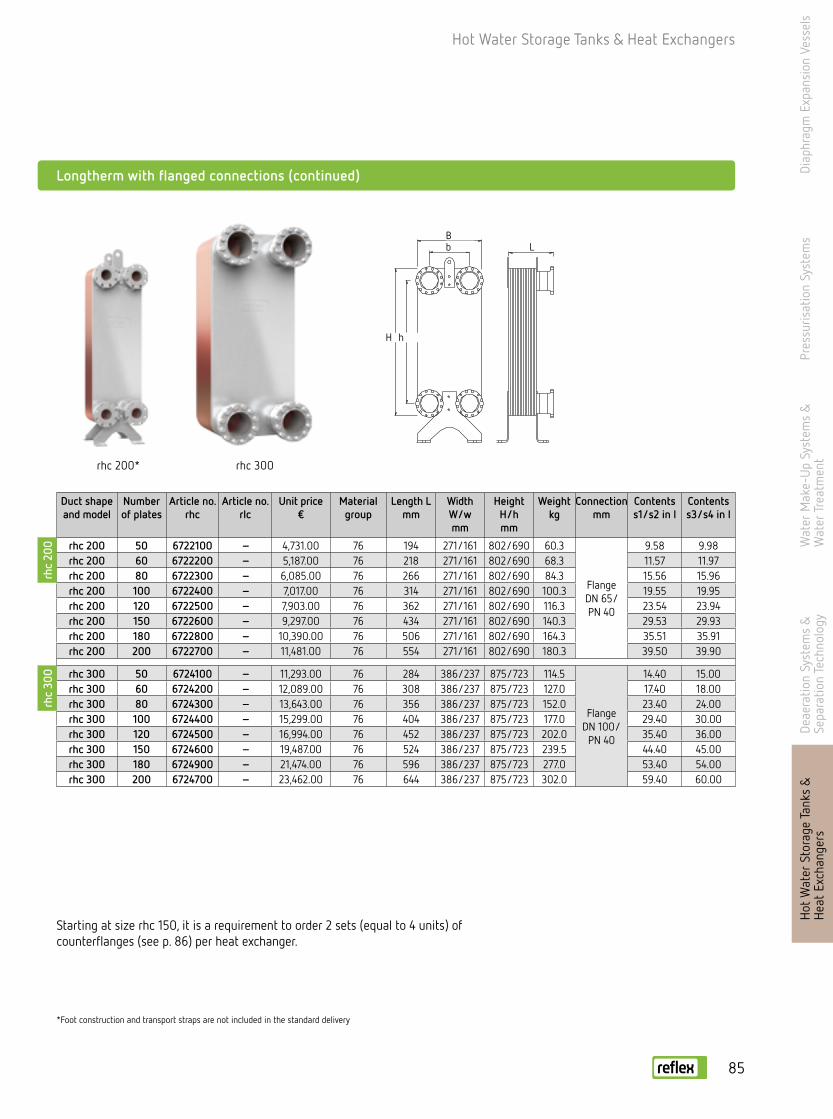
Hot Water Storage Tanks & Heat Exchangers
*Foot construction and transport straps are not included in the standard delivery
Starting at size rhc 150, it is a requirement to order 2 sets (equal to 4 units) of counterflanges (see p. 86) per heat exchanger.
Longtherm with flanged connections (continued)
Duct shape and model
Number of plates
Article no.rhc
Article no.rlc
Unit price€
Material group
Length Lmm
Width W/wmm
Height H/hmm
Weightkg
Connection mm
Contents s1/s2 in l
Contents s3/s4 in l
rhc 200 50 6722100 – 4,731.00 76 194 271/161 802/690 60.3
FlangeDN 65/ PN 40
9.58 9.98rhc 200 60 6722200 – 5,187.00 76 218 271/161 802/690 68.3 11.57 11.97rhc 200 80 6722300 – 6,085.00 76 266 271/161 802/690 84.3 15.56 15.96rhc 200 100 6722400 – 7,017.00 76 314 271/161 802/690 100.3 19.55 19.95rhc 200 120 6722500 – 7,903.00 76 362 271/161 802/690 116.3 23.54 23.94rhc 200 150 6722600 – 9,297.00 76 434 271/161 802/690 140.3 29.53 29.93rhc 200 180 6722800 – 10,390.00 76 506 271/161 802/690 164.3 35.51 35.91rhc 200 200 6722700 – 11,481.00 76 554 271/161 802/690 180.3 39.50 39.90
rhc 300 50 6724100 – 11,293.00 76 284 386/237 875/723 114.5
FlangeDN 100/
PN 40
14.40 15.00rhc 300 60 6724200 – 12,089.00 76 308 386/237 875/723 127.0 17.40 18.00rhc 300 80 6724300 – 13,643.00 76 356 386/237 875/723 152.0 23.40 24.00rhc 300 100 6724400 – 15,299.00 76 404 386/237 875/723 177.0 29.40 30.00rhc 300 120 6724500 – 16,994.00 76 452 386/237 875/723 202.0 35.40 36.00rhc 300 150 6724600 – 19,487.00 76 524 386/237 875/723 239.5 44.40 45.00rhc 300 180 6724900 – 21,474.00 76 596 386/237 875/723 277.0 53.40 54.00rhc 300 200 6724700 – 23,462.00 76 644 386/237 875/723 302.0 59.40 60.00
rhc 300 rhc 200*
Lb
B
hH
Lb
B
hH
rhc
200
rhc
300
Bb L
H h
Diap
hrag
m E
xpan
sion
Ves
sels
Pres
suris
atio
n Sy
stem
sW
ater
Mak
e-U
p Sy
stem
s &
W
ater
Tre
atm
ent
Deae
ratio
n Sy
stem
s &
Se
para
tion
Tech
nolo
gyH
ot W
ater
Sto
rage
Tank
s &
H
eat
Exch
ange
rs
85

Diap
hrag
m E
xpan
sion
Ves
sels
Pres
suris
atio
n Sy
stem
sW
ater
Mak
e-U
p Sy
stem
s &
W
ater
Tre
atm
ent
Deae
ratio
n Sy
stem
s &
Se
para
tion
Tech
nolo
gyH
ot W
ater
Sto
rage
Tank
s &
H
eat
Exch
ange
rsHot Water Storage Tanks & Heat Exchangers
Longtherm connection options
• Flat-sealed threaded connections, including seal, system connection as external thread, soldered end or welded end
• Starting at size rhc 150, the heat exchangers are equipped with special flanges• Set, consisting of 2 units, only delivered as a set
G1
L
G2
G
L
Ø
G
L
Ø
Ø
With external thread – brass
With welded end – steel
With soldered end – brass
Counterflange – stainless steel
Counterflange – steel
Screw connec-tion for type
Article no. Set price €
Material group G 1 G 2 Lmm
rhc 15 6762100 42.10 77 ¾ ½ 36rhc 40 6762200 47.80 77 1 ¾ 41rhc 60 6762300 64.40 77 1 ¼ 1 51r...c 85 6762400 83.90 77 2 1 ½ 60rhc 150 6762500 410.00 77 2 ½ 2 66rhc 200 6762500 410.00 77 2 ½ 2 66
Screw connec-tion for type
Article no. Set price €
Material group G 1 Ømm
Lmm
rhc 15 6760100 22.50 77 ¾ 21.2 30rhc 40 6760200 25.20 77 1 26.9 30rhc 60 6760300 39.20 77 1 ¼ 33.7 40r...c 85 6760400 42.10 77 2 48.3 40rhc 150 6760500 289.00 77 2 ½ 60.3 50rhc 200 6760500 289.00 77 2 ½ 60.3 50
Screw connec-tion for type
Article no. Set price€
Material group G 1 Ømm
Lmm
rhc 15 6761100 19.60 77 ¾ 18 16rhc 40 6761200 30.80 77 1 22 19rhc 60 6761300 36.30 77 1 ¼ 28 22
Flange for type
Article no. Set price €
Material group DN Ømm
rhc 150 6770200 201.00 77 65 76.1rhc 200 6770200 201.00 77 65 76.1rhc 300 6770400 452.00 77 100 114.3
Flange for type
Article no. Set price€
Material group DN Ømm
rhc 150 6770100 101.00 77 65 76.1rhc 200 6770100 101.00 77 65 76.1rhc 300 6770300 297.00 77 100 114.3
When ordering, we recommend ordering 2 sets (equal to 4 units) of counter-flanges per heat exchanger.
86
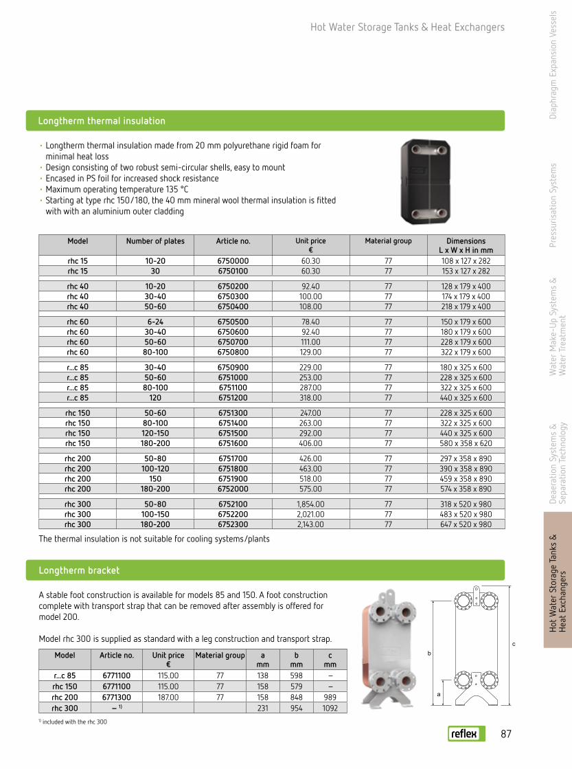
Hot Water Storage Tanks & Heat Exchangers
Diap
hrag
m E
xpan
sion
Ves
sels
Pres
suris
atio
n Sy
stem
sW
ater
Mak
e-U
p Sy
stem
s &
W
ater
Tre
atm
ent
Deae
ratio
n Sy
stem
s &
Se
para
tion
Tech
nolo
gy
Longtherm thermal insulation
Longtherm bracket
1) included with the rhc 300
• Longtherm thermal insulation made from 20 mm polyurethane rigid foam for minimal heat loss
• Design consisting of two robust semi-circular shells, easy to mount • Encased in PS foil for increased shock resistance• Maximum operating temperature 135 °C• Starting at type rhc 150/180, the 40 mm mineral wool thermal insulation is fitted
with with an aluminium outer cladding
A stable foot construction is available for models 85 and 150. A foot construction complete with transport strap that can be removed after assembly is offered for model 200.
Model rhc 300 is supplied as standard with a leg construction and transport strap.
Model Number of plates Article no.
Unit price€
Material group DimensionsL x W x H in mm
rhc 15 10-20 6750000 60.30 77 108 x 127 x 282rhc 15 30 6750100 60.30 77 153 x 127 x 282
rhc 40 10-20 6750200 92.40 77 128 x 179 x 400rhc 40 30-40 6750300 100.00 77 174 x 179 x 400rhc 40 50-60 6750400 108.00 77 218 x 179 x 400
rhc 60 6-24 6750500 78.40 77 150 x 179 x 600rhc 60 30-40 6750600 92.40 77 180 x 179 x 600rhc 60 50-60 6750700 111.00 77 228 x 179 x 600rhc 60 80-100 6750800 129.00 77 322 x 179 x 600
r...c 85 30-40 6750900 229.00 77 180 x 325 x 600r...c 85 50-60 6751000 253.00 77 228 x 325 x 600r...c 85 80-100 6751100 287.00 77 322 x 325 x 600r...c 85 120 6751200 318.00 77 440 x 325 x 600
rhc 150 50-60 6751300 247.00 77 228 x 325 x 600rhc 150 80-100 6751400 263.00 77 322 x 325 x 600rhc 150 120-150 6751500 292.00 77 440 x 325 x 600rhc 150 180-200 6751600 406.00 77 580 x 358 x 620
rhc 200 50-80 6751700 426.00 77 297 x 358 x 890rhc 200 100-120 6751800 463.00 77 390 x 358 x 890rhc 200 150 6751900 518.00 77 459 x 358 x 890rhc 200 180-200 6752000 575.00 77 574 x 358 x 890
rhc 300 50-80 6752100 1,854.00 77 318 x 520 x 980rhc 300 100-150 6752200 2,021.00 77 483 x 520 x 980rhc 300 180-200 6752300 2,143.00 77 647 x 520 x 980
Model Article no. Unit price€
Material group amm
bmm
cmm
r...c 85 6771100 115.00 77 138 598 –rhc 150 6771100 115.00 77 158 579 –rhc 200 6771300 187.00 77 158 848 989rhc 300 – 1) 231 954 1092
a
bc
The thermal insulation is not suitable for cooling systems/plantsH
ot W
ater
Sto
rage
Tank
s &
H
eat
Exch
ange
rs
87
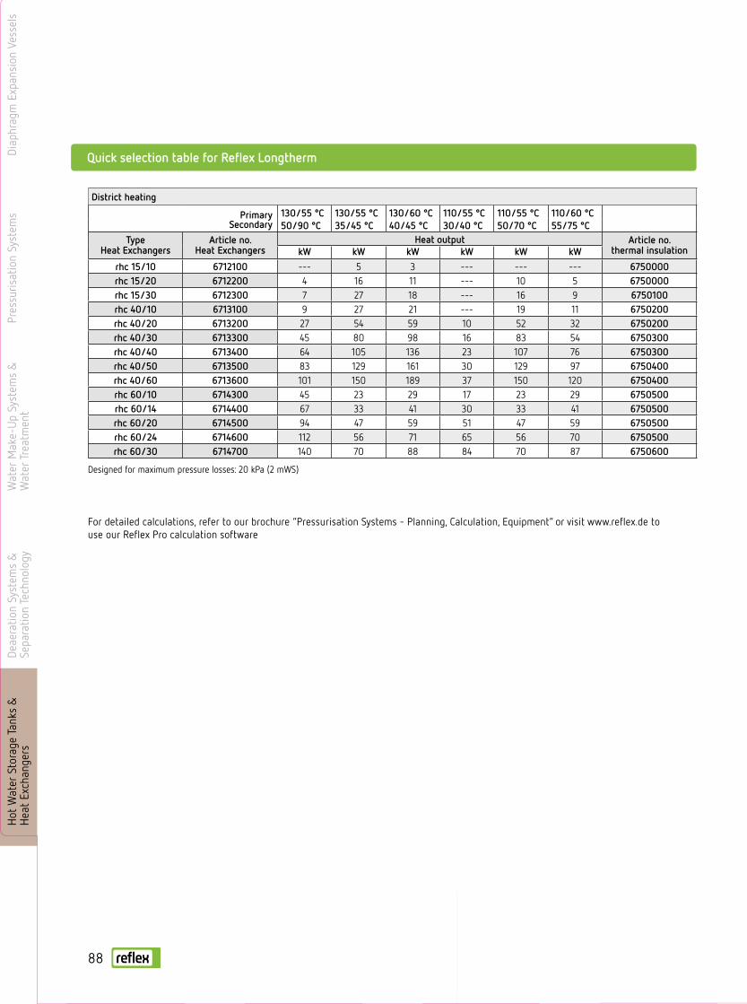
Diap
hrag
m E
xpan
sion
Ves
sels
Pres
suris
atio
n Sy
stem
sW
ater
Mak
e-U
p Sy
stem
s &
W
ater
Tre
atm
ent
Deae
ratio
n Sy
stem
s &
Se
para
tion
Tech
nolo
gyH
ot W
ater
Sto
rage
Tank
s &
H
eat
Exch
ange
rs
District heating
PrimarySecondary
130/55 °C 130/55 °C 130/60 °C 110/55 °C 110/55 °C 110/60 °C50/90 °C 35/45 °C 40/45 °C 30/40 °C 50/70 °C 55/75 °C
Type Heat Exchangers
Article no.Heat Exchangers
Heat output Article no.thermal insulationkW kW kW kW kW kW
rhc 15/10 6712100 --- 5 3 --- --- --- 6750000rhc 15/20 6712200 4 16 11 --- 10 5 6750000rhc 15/30 6712300 7 27 18 --- 16 9 6750100rhc 40/10 6713100 9 27 21 --- 19 11 6750200rhc 40/20 6713200 27 54 59 10 52 32 6750200rhc 40/30 6713300 45 80 98 16 83 54 6750300rhc 40/40 6713400 64 105 136 23 107 76 6750300rhc 40/50 6713500 83 129 161 30 129 97 6750400rhc 40/60 6713600 101 150 189 37 150 120 6750400rhc 60/10 6714300 45 23 29 17 23 29 6750500rhc 60/14 6714400 67 33 41 30 33 41 6750500rhc 60/20 6714500 94 47 59 51 47 59 6750500rhc 60/24 6714600 112 56 71 65 56 70 6750500rhc 60/30 6714700 140 70 88 84 70 87 6750600
Designed for maximum pressure losses: 20 kPa (2 mWS)
For detailed calculations, refer to our brochure “Pressurisation Systems - Planning, Calculation, Equipment” or visit www.reflex.de to use our Reflex Pro calculation software
Quick selection table for Reflex Longtherm
88

Services
Diap
hrag
m E
xpan
sion
Ves
sels
Pres
suris
atio
n Sy
stem
sW
ater
Mak
e-U
p Sy
stem
s &
W
ater
Tre
atm
ent
Deae
ratio
n Sy
stem
s &
Se
para
tion
Tech
nolo
gyH
ot W
ater
Sto
rage
Tank
s &
H
eat
Exch
ange
rsSe
rvic
es

Count on us - from the initial id ea to the solution
Reflex offer a range of services to assist you in finding the solution that best suits your needs. Take advantage of our combined expertise and experience and develop professional solutions together with us, down to the very last detail.
Made-to-measure design: With the Reflex Pro calculation program
Take the easiest route to correct design and sizing: Reflex Pro is the proven, continuously developed software solu-tion you can use to quickly and simply achieve precise results.The software is available in three versions and we also offer a CAD library of our products for integration into your construction programmes.
Visit www.reflex.de/pro for further information and the option of downloading free of charge.
Reflex Pro Web
The online version calculates pressure retention and heat transfer systems in a few simple steps. The results are provided in the form of a PDF or text file for further use.
Reflex Pro App
Reflex Pro is available as an app for iPhone, iPad and iPod touch! Whether you need to make a quick calculation on site or design a project on your mobile – you will always leave a profes-sional impression with your customers with the Reflex Pro app.
Reflex Pro Win
The full range of services for convenient use even without an Internet connec-tion. The download version for Windows systems is perfect when you are regu-larly planning and designing pressure retention and heat transfer systems.
Diap
hrag
m E
xpan
sion
Ves
sels
Pres
suris
atio
n Sy
stem
sW
ater
Mak
e-U
p Sy
stem
s &
W
ater
Tre
atm
ent
Deae
ratio
n Sy
stem
s &
Se
para
tion
Tech
nolo
gyH
ot W
ater
Sto
rage
Tank
s &
H
eat
Exch
ange
rsServices
Serv
ices 90

Count on us - from the initial id ea to the solution
Our product literature - designed to be used
Make sure your decisions about all future steps are based on solid foundations – with Reflex product information. You will find everything you need to know about products and systems in our brochures and at www.reflex.de. Well arranged and clearly explained – from the wider context to technical details.
Request the latest Reflex brochures directly from your Reflex field sales engineer, via our central phone number or – even simpler – online as PDFs at www.reflex.de.
Our field sales team - always on the road for you
Our Reflex field sales team is your first point of contact when you need professional advice on site. From recommending relevant products to design and support in the preparation of a tender. You can rely on our experts!
Call our central phone number or check out www.reflex.de under Contact Us to find the field sales representative re-sponsible for your region.
Diap
hrag
m E
xpan
sion
Ves
sels
Pres
suris
atio
n Sy
stem
sW
ater
Mak
e-U
p Sy
stem
s &
W
ater
Tre
atm
ent
Deae
ratio
n Sy
stem
s &
Se
para
tion
Tech
nolo
gyH
ot W
ater
Sto
rage
Tank
s &
H
eat
Exch
ange
rsSe
rvic
es
Services
91

Diap
hrag
m E
xpan
sion
Ves
sels
Pres
suris
atio
n Sy
stem
sW
ater
Mak
e-U
p Sy
stem
s &
W
ater
Tre
atm
ent
Deae
ratio
n Sy
stem
s &
Se
para
tion
Tech
nolo
gyBu
ffer
sto
rage
tan
ks &
he
at e
xcha
nger
sServices
How to reach us? It's easy!
This brochure presents a wide range of our services on offer. Our priority is to make using our services as simple as possible for you. That's why we have included a summary of all our contact information once again for you here. You can also visit our website at www.reflex.de for the latest information and extensive offers. We look forward to receiving your enquiry!
International +49 2382 7069-... Extension Fax Head of OEM Business Rein van Rijt -9559 -39 559 [email protected] of Supply Chain Management Hendrik Westhölter -9541 -39 541 [email protected]
Internal Sales Assistant Stefan Echtermann -9528 -39 528 [email protected] Lydia Kreibel -9563 -39 563 [email protected] Florence Margout -9509 -39 509 [email protected] Tanja Sell -9571 -39 562 [email protected]
Int. Technical Manager Willem Tieleman +49 151 18 02 40 30 [email protected] Lars Leer +45 40 56 18 88 [email protected]
Region Central Europe
Reflex NordicJohan RoennbladRatakatu 610300 KarjaaFinlandMobile: +358 40 160 [email protected]
Reflex RomaniaAndrei Stoican2nd District, 15 Oltetului Street, 023871 Bucharest, RomaniaPhone: +40 318 170 713 Fax: +40 133 180 82 Mobile: +40 751 248 [email protected]
Region Western Europe
Reflex Belux Michel BlainMobile: +32 474 59 80 [email protected]
Regional Sales Director: Peter Schmid
Regional Sales Director: Frédéric Passot
Reflex Austria GmbHWolfgang BurianekHirschstettner Strasse 19-21 BT. I/3. OG 1220 Vienna, AustriaPhone: +43 1 616 02 510 Fax: +43 1 616 02 50 [email protected]@reflex-austria.atwww.reflex-austria.at
Reflex Balkans, BulgariaWolfgang BurianekMobile: +43 664 883 88841 [email protected]
Reflex Nederland B.V.Roderick van GeelKerkstraat 2a2971 AL Bleskensgraaf CAThe NederlandsPhone: +31 184 67 05 30 Fax: +31 184 67 05 [email protected]
Reflex HungaryDomotech Bt Peter GösiFalk Miksa ú 41055 BudapestHungary Phone/Fax: +36 133 180 82Mobile: +36 309 311 850 [email protected]
Reflex Switzerland GmbHRoger Fisch Hohenrainstrasse 10 4133 Pratteln, SwitzerlandPhone: +41 61 825 69 52 Fax: +41 61 825 69 [email protected]
Reflex FranceFrédéric PassotPhone/Fax: +33 628 635 [email protected]
Reflex Spain, PortugalFrédéric Passot Mobile: +34 608 56 79 47 [email protected]
Reflex Hellas A.E.Tina LamprinidouVouliagmenis Av. 16517237 DafniGreecePhone: +30 210 67 14 737 Fax: +30 210 67 14 [email protected]@reflex-hellas.grwww.reflex.de
Reflex ItalyWalter BachmannMobile: +39 348 688 [email protected]
Reflex UK + Ireland Tim WilliamsPhone: +44 77 02 49 31 [email protected]
Serv
ices 92

Diap
hrag
m E
xpan
sion
Ves
sels
Pres
suris
atio
n Sy
stem
sW
ater
Mak
e-U
p Sy
stem
s &
W
ater
Tre
atm
ent
Deae
ratio
n Sy
stem
s &
Se
para
tion
Tech
nolo
gyH
ot W
ater
Sto
rage
Tank
s &
H
eat
Exch
ange
rsSe
rvic
es
Services
How to reach us? It's easy!
Region Middle East/Africa
Reflex TurkeyDaghan InalGrezan Plaza No: 1/8 Kayisdagi Cad.34398 Istanbul TurkeyMobile: +90 549 605 52 [email protected]
Reflex AfricaMoustapha FahmyArkan PlazaSheikh Zayed city6th October/GizaEgyptMobile: +49 151 180 242 [email protected]
Reflex GCCPramod KadkolP.O. Box 125084DubaiUAEPhone/Fax: +97 150 340 [email protected]
Region Asia/Pacific
Reflex Asia/PacificMichael WolfGersteinstrasse 1959227 AhlenGermanyPhone: +49 2382 7069-9533Fax: +49 2382 7069-39 533Mobile: +49 151 11 72 29 [email protected]
Region America
Reflex AmericaMichael Wolf Gersteinstrasse 19 59227 AhlenGermanyPhone: +49 2382 7069-9522 Fax: +49 2382 7069-39 [email protected]
Region China
Reflex (Shanghai) Heating & Energy Equipment Ltd. CoTommy CaoNo. 159 Renbao Rd. Fengchen Town, Fenxian District201408 Shanghai, P. R. ChinaPhone: +86 21 57171822-168Fax: +86 21 57171833Mobile: +86 136 3654 [email protected]
Regional Sales Director: Moustapha Fahmy
Region Eastern Europe
Reflex POLSKA Sp. z o.o.Dr. Alfred Jerszynskiul. Swojska 1360-592 Poznán PolandPhone: +48 61 653 14 02Fax: +48 61 653 14 [email protected]
Reflex SK, s.r.o.Dipl.-Ing. Peter PáltikRakovo 038 42 PribovceSlovac RepublicPhone: +421 43 423 0983Fax: +421 43 423 [email protected]
Reflex CZ, s.r.o.Vit GabrielSezemická 2757/2193 00 Prag 9 Czech RepublicPhone: +420 272 090 301 Fax: +420 272 090 [email protected] [email protected] www.reflexcz.cz
Office Reflex Russia Konstantin Ortlieb Kastomarowskij Per 3 105120 MoscowRussia Phone: +7 495 363 15 49Fax: +7 495 363 11 84Mobile: +7 903 009 [email protected]
Reflex BaltikumVygantas MilaknisP.O. Box 1542002 RokiškisLithuaniaFax: +370 458 31 244Mobile: +370 687 27 [email protected]
Reflex Kazakhstan, Belarus, UkraineAnatol PivtorakMobile: +380 67 408 [email protected]
Regional Sales Director: Jacek Kieszkowski
93

Please also see our General Terms and Conditions of Delivery, available for download on our homepage www.reflex.de.
General Terms and Conditions of Business and DeliveryDi
aphr
agm
Exp
ansi
on V
esse
lsPr
essu
risat
ion
Syst
ems
Wat
er M
ake-
Up
Syst
ems
&
Wat
er T
reat
men
tDe
aera
tion
Syst
ems
&
Sepa
ratio
n Te
chno
logy
Buff
er s
tora
ge t
anks
&
heat
exc
hang
ers
Serv
ices 94

Services
Diap
hrag
m E
xpan
sion
Ves
sels
Pres
suris
atio
n Sy
stem
sW
ater
Mak
e-U
p Sy
stem
s &
W
ater
Tre
atm
ent
Deae
ratio
n Sy
stem
s &
Se
para
tion
Tech
nolo
gyH
ot W
ater
Sto
rage
Tank
s &
H
eat
Exch
ange
rsSe
rvic
es95

PI13
41en
/ 9
1199
43 /
02
- 14
Su
bjec
t to
tech
nica
l mod
ifica
tions
Reflex Winkelmann GmbHGersteinstrasse 19
59227 Ahlen, Germany
Tel.: +49 2382 7069-0Fax: +49 2382 7069-588
www.reflex.de