Embed Size (px)
Citation preview

Product review
Primary flow elements

2
Contents
Part of your business
WIKA product lines 3
Everything at a glance 4
Orifice plates and assemblies 6
Meter runs 8
Flow nozzles 9
Venturi tubes 10
FloTec (averaging pitot tubes) 11
Restriction orifices 12
The right solution 13
Technical information 14
WIKA worldwide 16
Ability to meet any challenge
Efficient logistics Fully automatic production
Certified calibration laboratories
As a family-run business acting globally, with over 8,500 highly qualified employees, the WIKA group of companies is a worldwide leader in pressure and temperature measurement. The company also sets the standard in the measurement of level and flow, and in calibration technology. Founded in 1946, WIKA is today a strong and reliable partner for all the requirements of industrial measurement technology, thanks to a broad portfolio of high-precision instruments and comprehensive services.
With manufacturing locations around the globe, WIKA ensures flexibility and the highest delivery performance. Every year, over 50 million quality products, both standard and customer-specific solutions, are delivered in batches of 1 to over 10,000 units. With numerous wholly-owned subsidiaries and partners, WIKA competently and reliably supports its customers worldwide. Our experienced engineers and sales experts are your competent and dependable contacts locally.

3
WIKA product lines
For all product lines product reviews are available.
The WIKA programme covers the following product lines for various fields of application.
WIKA product lines
Electronic pressure measurementWIKA offers a complete range of electronic pressure measuring instruments: pressure sensors, pressure switches, pressure transmitters and process transmitters for the measurement of gauge, absolute and differential pressure. Our pressure measuring instruments are available in the measuring ranges 0 … 0.6 mbar to 0 … 15,000 bar. These instruments come supplied with standardised current or voltage output signals (also intrinsically safe per ATEX or with flameproof enclosure), interfaces and protocols for various field buses. Whether ceramic thick film, metal thin film or piezo-resistive, WIKA is the leading manufacturer worldwide that develops and produces the full range of today’s leading sensor technologies.
Mechatronic pressure measurementAs a result of the almost unlimited options for different combinations of mechanical and electrical connections, an extraordinary range of instrument variants is possible. Various digital and analogue output signals are also available for these measuring instruments.For our measuring instruments we use latest sensors, tested in automotive applications millions of times over. They work without any kind of mechanical contact, consequently they are wear-resistant, and there's absolutely no influence on the mechanics.
Mechanical pressure measurementIndicating pressure gauges for gauge, absolute and dif-ferential pressure with Bourdon tube, diaphragm or capsule pressure elements have been tested millions of times over. These instruments cover scale ranges from 0 … 0.5 mbar to 0 … 7,000 bar and indication accuracies of up to 0.1 %.
Diaphragm sealsWIKA diaphragm seals, mounted with pressure gauges, pressure transducers, pressure transmitters etc., are recognised and valued internationally for the most difficult of measuring tasks. The measuring instruments can therefore be used at extreme temperatures (-130 … +400 °C), and with aggressive, corrosive, heterogeneous, abrasive, highly viscous or toxic media. The optimal diaphragm seal designs, materials and filling media are available for each application.
Electrical temperature measurementOur range of products includes thermocouples, resistance thermometers (also with on-site display), temperature switches as well as analogue and digital temperature transmitters for all industrial applications. Measuring ranges from -200 … +1,700 °C are covered.
Mechatronic temperature measurementAs a result of the integration of switch contacts and output signals into our mechanical temperature measuring instru-ments, we can offer a wide variety of combined instruments. With switch contacts the pointer position triggers a change-over. Electrical output signals are realised via an additional, independent sensor circuit (resistance thermometer or thermocouple).
Mechanical temperature measurementThe mechanical temperature measuring instruments work on the bimetal, expansion or gas actuation principle and cover scale ranges from -200 … +700 °C. All thermometers are suited for operation in a thermowell if necessary.
Level measurementWIKA has a comprehensive range of level measuring instruments available for temperatures up to 450 °C, specific gravity from 400 kg/m³ and pressure ranges up to 500 bar. This includes standard instruments and customised products.
Flow measurementOrifice plates, meter runs, flow nozzles, Venturi tubes and pitot tubes are part of our portfolio of primary flow elements and restriction orifices. The wide range of our products is able to cover the majority of industrial applications. Customised solutions can be developed to meet your special needs.
Calibration technologyWIKA offers a broad product range of calibration instruments for the physical units of measurement for pressure and temperature, and for electrical measurands. Numerous patents ensure unmatched performance from many of our calibration instruments. The range of services covers the calibration of pressure and temperature measuring instruments in our accredited DKD/DAkkS calibration laboratories and a mobile service to calibrate your instruments on site.
4
Primary flow elements
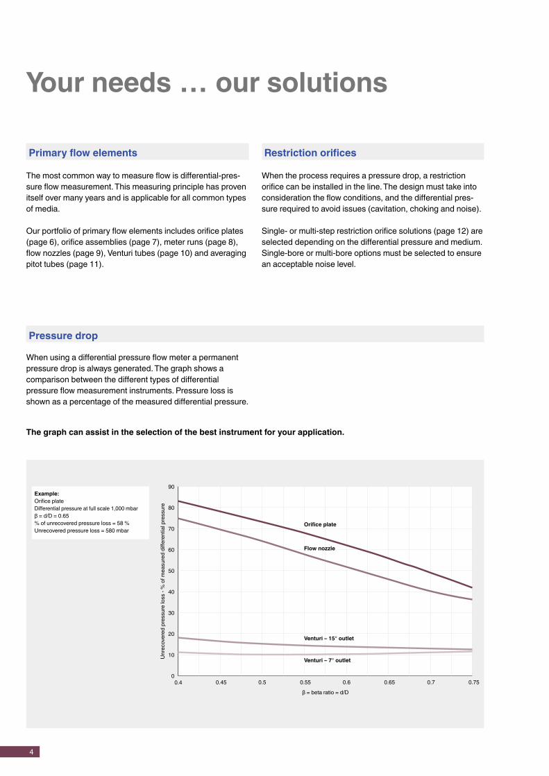
The most common way to measure flow is differential-pres-sure flow measurement. This measuring principle has proven itself over many years and is applicable for all common types of media.
Our portfolio of primary flow elements includes orifice plates (page 6), orifice assemblies (page 7), meter runs (page 8), flow nozzles (page 9), Venturi tubes (page 10) and averaging pitot tubes (page 11).
Pressure drop
Restriction orifices
When the process requires a pressure drop, a restriction orifice can be installed in the line. The design must take into consideration the flow conditions, and the differential pres-sure required to avoid issues (cavitation, choking and noise).
Single- or multi-step restriction orifice solutions (page 12) are selected depending on the differential pressure and medium. Single-bore or multi-bore options must be selected to ensure an acceptable noise level.
Your needs … our solutions
When using a differential pressure flow meter a permanent pressure drop is always generated. The graph shows a comparison between the different types of differential pressure flow measurement instruments. Pressure loss is shown as a percentage of the measured differential pressure.
90
80
70
60
50
40
30
20
10
0
Example:Orifice plateDifferential pressure at full scale 1,000 mbarβ = d/D = 0.65% of unrecovered pressure loss = 58 %Unrecovered pressure loss = 580 mbar
Unre
cove
red
pres
sure
loss
- %
of m
easu
red
diffe
rent
ial p
ress
ure
β = beta ratio = d/D0.4 0.45 0.5 0.55 0.6 0.65 0.7 0.75
The graph can assist in the selection of the best instrument for your application.
Orifice plate
Flow nozzle
Venturi – 15° outlet
Venturi – 7° outlet

5
Everything at a glance
Medium characteristics
Not all instruments can be used in all applications. The type of medium (gas, liquid or steam) and its conditions must be taken into account when selecting the right instrument for your medium condition.
The following selection chart will assist in choosing the right instrument:
Reynolds number
Your needs … our solutions
Orifice plate and related assemblies(Orifice flange / Meter run / Annular chambers)
Flow nozzle
Venturi tube Pitot tube
Square edge Quarter circle Conical entrance
Eccentric Segmental
GasClean ++ – – + + ++ ++ ++Dirty – – – ++ ++ + + –
Liquid
Clean ++ ++ ++ + + ++ ++ ++Viscous – ++ ++ – – + + +Dirty + + + ++ ++ + + –Corrosive + + + + + + + +
Steam + + + + + ++ + –Page 6 … 8 9 10 11
Dimensions Reynolds numberN ND
Orifice plate and related assemblies
Orifice flangeMeter runAnnular chambers
Integral < 1.5" < 40 > 100
Square edge > 1.5" > 40 > 2,000
Quarter circle > 1.5" > 40 > 200
Conical entrance > 1.5" > 40 > 200
Eccentric > 4" > 100 > 10,000
Segmental > 4" > 100 > 1,000
Flow nozzle > 2" > 50 > 75,000
Venturi tube > 2" > 50 > 12,500
Pitot tube > 4” > 100 no limits
It is difficult to evaluate the many variables affecting the velocity profile for all flow meters and for all pipeline conditions. To combine medium properties (density and viscosity), flow rate and geometrical aspects the Reynolds number is used.
The table shows you the smallest possible Reynolds number that can be used with each instrument.
++ Preferred + Suitable – Not suitable

6
Orifice plates represent the most common primary flow elements in the world due to their proven technology and ease of installation and maintenance.
Main characteristics � Maximum operating temperature up to 800 °C � Maximum operating pressure up to 400 bar � Suitable for liquid, gas and steam flow measurement � Accuracy ±0.5 ... 2.5 % � Repeatability of measurement 0.1 %
Orifice plates and assemblies
FLC-OPOrifice plate
Standards: ■ ISO 5167-2 ■ ASME MFC3M
Pipe size: ■ ≥ 2" ■ ≥ 50 mm
β: Depending on versionAccuracy: 1) uncalibrated ±0.5 ... 2.5 %Data sheet: FL 10.01
Detail
Detail
Detail
Detail
Designs
� Square edge orifice plates (standard version) This design is intended for general applications in clean liquids and gases.
� Quarter circle and conical entrance orifice plates The best choice for measurement of liquids with low Reynolds number.
� Segmental orifice plates For measurements with two-phase, dirty and particle-laden media.
� Eccentric orifice plates The application areas are similar to the segmental version. However, an eccentric orifice plate is the better solution for smaller pipe diameters.
β: 0.10 … 0.75
Conical entrance: β 0.10 … 0.316Quarter circle: β 0.245 … 0.60
β: 0.35 … 0.85
β: 0.46 … 0.84
1) The actual measuring deviation is specified during the engineering phase

7
Orifice plates and assemblies
FLC-FLOrifice flanges
Standards: ISO 5167-2Pipe size: ■ ≥ 2"
■ ≥ 50 mmβ: Depending on versionAccuracy: 1) Uncalibrated ±0.5 ... 2.5 %Data sheet: FL 10.01
FLC-ACAnnular chambers
Standards: ISO 5167-2Pipe size: ■ ≥ 2"
■ ≥ 50 mmβ: Depending on versionAccuracy: 1) Uncalibrated ±0.5 ... 2.5 %Data sheet: FL 10.01
Orifice flanges are intended for use instead of standard pipe flanges when an orifice plate or flow nozzle must be installed. Pairs of pressure tappings are machined into the orifice flange, making separate orifice carriers or tappings in the pipe wall unnecessary.
Main characteristics � Wide range of materials available � The number and type of pressure tapping (flange
tap or corner tap) can be manufactured to customer requirements
� Special assemblies can be designed on request
Annular chambers are designed to be mounted between standard pipe flanges. Versions are available to suit all common flange standards, including DIN and ANSI B16.5.
Main characteristics � Standard material is 316/316L stainless steel, but a wide
range of alternative materials is available � Gaskets are included in the scope of delivery (as standard,
4.4 mm thick spiral-wound gasket 316/graphite filler, unless requested otherwise)
8
Meter runs
Meter runs
FLC-MRMeter run
Standards: ISO 5167-2Pipe size: ■ ½ … 1½ in
■ 12 … 40 mmβ: 0.2 … 0.75Accuracy: Uncalibrated ±1 ... 2 %Data sheet: FL10.02
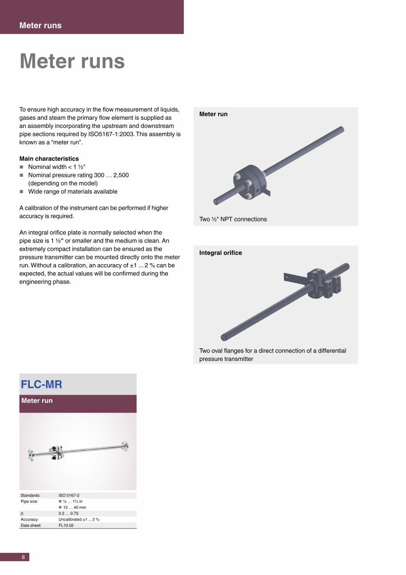
To ensure high accuracy in the flow measurement of liquids, gases and steam the primary flow element is supplied as an assembly incorporating the upstream and downstream pipe sections required by ISO5167-1:2003. This assembly is known as a “meter run”.
Main characteristics � Nominal width < 1 ½" � Nominal pressure rating 300 … 2,500
(depending on the model) � Wide range of materials available
A calibration of the instrument can be performed if higher accuracy is required.
An integral orifice plate is normally selected when the pipe size is 1 ½" or smaller and the medium is clean. An extremely compact installation can be ensured as the pressure transmitter can be mounted directly onto the meter run. Without a calibration, an accuracy of ±1 ... 2 % can be expected, the actual values will be confirmed during the engineering phase.
Two ½" NPT connections
Meter run
Integral orifice
Two oval flanges for a direct connection of a differential pressure transmitter
9
Flow nozzles
Flow nozzles
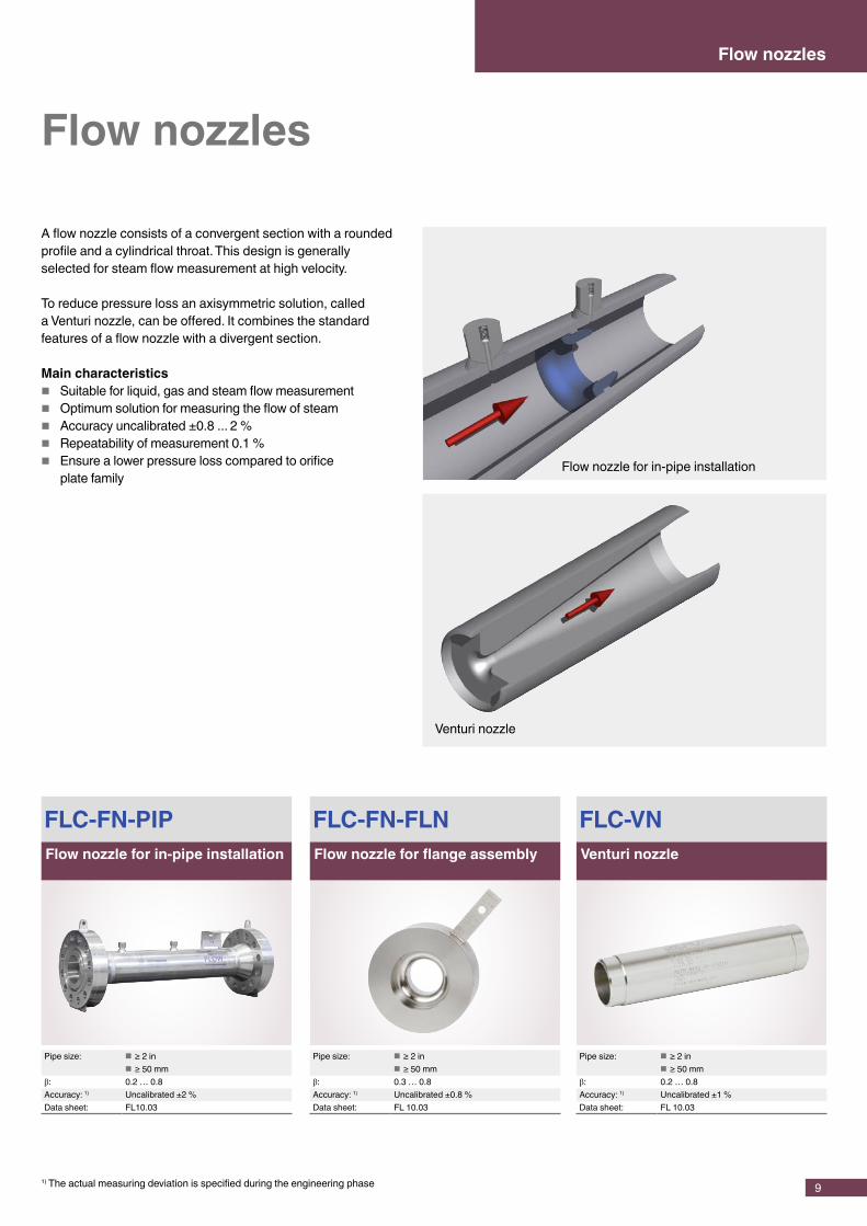
A flow nozzle consists of a convergent section with a rounded profile and a cylindrical throat. This design is generally selected for steam flow measurement at high velocity.
To reduce pressure loss an axisymmetric solution, called a Venturi nozzle, can be offered. It combines the standard features of a flow nozzle with a divergent section.
Main characteristics � Suitable for liquid, gas and steam flow measurement � Optimum solution for measuring the flow of steam � Accuracy uncalibrated ±0.8 ... 2 % � Repeatability of measurement 0.1 % � Ensure a lower pressure loss compared to orifice
plate family
FLC-FN-FLNFlow nozzle for flange assembly
Pipe size: ■ ≥ 2 in ■ ≥ 50 mm
β: 0.3 … 0.8Accuracy: 1) Uncalibrated ±0.8 %Data sheet: FL 10.03
FLC-FN-PIPFlow nozzle for in-pipe installation
Pipe size: ■ ≥ 2 in ■ ≥ 50 mm
β: 0.2 … 0.8Accuracy: 1) Uncalibrated ±2 %Data sheet: FL10.03
FLC-VNVenturi nozzle
Pipe size: ■ ≥ 2 in ■ ≥ 50 mm
β: 0.2 … 0.8Accuracy: 1) Uncalibrated ±1 %Data sheet: FL 10.03
Flow nozzle for in-pipe installation
Venturi nozzle
1) The actual measuring deviation is specified during the engineering phase

10
Venturi tubes
A Venturi tube is a reliable and easily-managed and main-tained instrument that can measure a wide range of clean liquids and gases.
The main advantage of a Venturi tube over other differential pressure flow measuring instruments is the higher pressure recovery and the lower upstream and downstream straight pipe length requirements.
Main characteristics � In accordance with ISO 5167-4 & ASME MFC-3M
standards � Fabricated from plate or machined from bar/forgings � Flanged or weld-in construction � Wide range of materials available � Pipe sizes from 50 … 1,200 mm � Wide variety of pressure tappings available � Calibration service available on request � Accuracy: uncalibrated ±1 ... 1.5 %
FLC-VT-BARVenturi tube, bar body
Pipe size: ■ 2 … 32 in ■ 50 … 250 mm
β: 0.4 … 0.75Accuracy: 1) Uncalibrated ±1.25 %Data sheet: FL 10.04
FLC-VT-WSVenturi tube, welded sheet
Pipe size: ■ ≥ 14 in ■ 200 … 1,200 mm
β: 0.4 … 0.7Accuracy: 1) Uncalibrated ±1.5 %Data sheet: FL 10.04
Venturi tubes
Venturi tube, bar body
1) The actual measuring deviation is specified during the engineering phase

11
FloTec (averaging pitot tubes)
FloTec (averaging pitot tubes)
Flotec (a multi-port, averaging pitot flow meter) measures the difference between the static pressure and the dynamic pressure of the media in the pipe. The volumetric flow is calculated from that difference using Bernoulli’s principle and taking into account the pipe inner diameter. Using four dynamic ports this instrument is able to evaluate a better velocity profile inside the pipe. This ensures a higher accuracy in the flow measurement.
Main characteristics � Low installation costs � Long-term accuracy � Minimal unrecovered pressure loss � Fixed and extractable versions available
Vortex generation
Vortex shedding frequencyDepending on the inner diameter, the medium characteristics and the Reynolds number, a vortex will be generated around the pitot tube. A support mounted on the opposite side of the pipe can be supplied should the natural frequency of the pitot coincide with the vortex shedding frequency. The necessity test is performed during the design phase.
FLC-APT-EFloTec, extractable
Pipe size: ■ ≥ 3 in ■ ≥ 50 … 1,800 mm
β: n.a.Accuracy: Uncalibrated ±3 %Data sheet: FL 10.05
FLC-APT-FFloTec, fixed
Pipe size: ■ ≥ 3 in ■ ≥ 50 … 1,800 mm
β: n.a.Accuracy: Uncalibrated ±3 %Data sheet: FL 10.05
12
FLC-RO-STSingle-step restriction orifice
Data sheet: FL 20.01
FLC-RO-MSMulti-step restriction orifice
Data sheet: FL 20.01
Multi-step restriction orifice
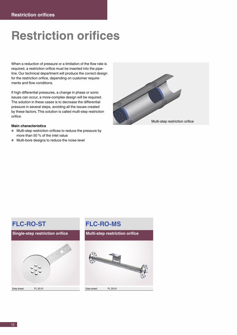
When a reduction of pressure or a limitation of the flow rate is required, a restriction orifice must be inserted into the pipe-line. Our technical department will produce the correct design for the restriction orifice, depending on customer require-ments and flow conditions.
If high differential pressures, a change in phase or sonic issues can occur, a more-complex design will be required. The solution in these cases is to decrease the differential pressure in several steps, avoiding all the issues created by these factors. This solution is called multi-step restriction orifice.
Main characteristics � Multi-step restriction orifices to reduce the pressure by
more than 50 % of the inlet value � Multi-bore designs to reduce the noise level
Restriction orifices
Restriction orifices

13
The right solution
Not all customer needs can be fulfilled with standard products. Some challenges require an individual approach: As a result of our long experience we are able to cover special require-ments such as off-shore and petrochemical installations, high-pressure lines and meter tubes for measurement in gas turbine power plants.
For all of these special applications and many more, we are able to deliver the optimal solution.Talk to us.
Special applications
The accuracy of the measuring solution is often an important issue for many customers.
Sometimes the end-user needs best-in-class measurement levels, in terms of accuracy, precision and repeatability of the measurement.
CalibrationWe can support you in this challenge through the entire design and manufacturing process - suggesting the best solution for your project, ensuring the highest class manufacturing quality and providing the relevant calibration certificates in accordance with ASME PTC6, ISPESL and IBR standards.

14
All our primary flow elements are designed in accordance with the principles and requirements of international standards:
� ISO 5167/ISO TR 15377 � ASME MFC � ASME PTC6 � BS 1042 � DIN 19206 � UNI 10023
Standards
Stainless steels are the standard materials used in industrial process technology. The most commonly used material worldwide is 316L. For high-pressure measurement, high-strength stainless steel is used, while for pressure measurements at elevated temperatures, temperature-resistant stainless steel is needed.
For chemical processes involving highly aggressive media an extensive range of chemically resistant materials is available. In these cases, all wetted parts are manufactured from the appropriate special material. Our primary flow elements are manufactured from 316L stainless steel as a standard.
International standards are our standard. We are able to deliver products in accordance with ASTM or ASME in line with your requirements. In addition we are able to offer materials to EN ISO 15156-3/NACE MR 0175 and NACE MR 0103 for the petrochemical industry.
All pressure-bearing materials used can be supplied with a 3.1 traceability certificate.
Materials � Carbon steel (ASTM A105/LF2) � Stainless steel (316/316L, 304/304L) � Duplex/Superduplex � Hastelloy® B3 � Hastelloy® C22 � Hastelloy® C276 (ASTM B426 UNS N10276) � Incoloy alloy 825 � Inconel alloy 718 � Monel alloy 400 (ASTM B564 UNS N0440)
Pressure equipment conformityIf required the technical documentation may be supplied with pressure equipment certificates. The European pressure equipment directive 97/23/EC must be applied to most mechanical and electrical pressure measuring instruments, throughout the European Union. For ABSA certification on instruments, Canadian design and construction requirements must be followed.
15
Technical information
Non-destructive test/evaluation
Non-destructive testing (NDT) and non-destructive evaluation (NDE). A number of different tests can be carried out by WIKA to determine deficiencies or defects in or on the surface of materials depending on your requirements.
Liquid penetrant inspection (LPI) is used to locate surface defects on relatively smooth and non-porous materials. This test method is normally used for welded parts to guaran-tee a good quality of the weld surface. Typical weld defects that can be discovered are cracks, porosities, overlaps and laminations.
Magnetic particle inspection (MPI) is a non-destructive test method for the detection of surface and sub-surface discontinuities in ferrous materials. The test method involves the application of an external magnetic field to the material or applying an electric current through the material, which in turn produces a magnetic flux in the material. Simultaneously, visible ferrous particles are sprinkled or sprayed on the test surface. The presence of a surface or near-surface discontinuity in the material causes distortion in the magnetic flux which in turn causes leakage of the magnetic field at the discontinuity. The magnetic particles are attracted by the surface field in the area of the discontinuity and adhere to the edges of the discontinuity, indicating the shape of the discontinuity.
X-ray testing (RT) is used extensively on the weld seams of pipes, fittings, etc.. The method is based on the differing absorption of penetrating radiation and thus it detects differ-ences in density due to material composition, thickenings and flaws. Defects are found internally and may typically be present in raw materials, castings, and forgings, as well as in welded and soldered joints. X-ray tests are normally used for components that must fulfil critical requirements. Irregularities or flaws that can be detected include: surface and internal cracks, voids, laminations, thickenings, lack of fusion, lack of penetration, excessive penetration, porosity, inclusions, misassembly and misalignments.
Hydrostatic pressure tests are used to (statically) test assemblies, piping systems and Venturi tubes under their working pressure. The hydrostatic pressure and strength test is conducted with water at ambient temperatures.
Ultrasonic testing is used as an independent test or in conjunction with X-ray testing. It is a method in which high frequency sound waves are introduced into a material. Any surface or subsurface discontinuities or flaws that are present interrupt the sound waves and reflect a proportion of them. The magnitude of the reflected waves depends on the size of the discontinuity or flaw. The defects that can be detected are similar to those that can be found through X-ray testing. Ultrasonic testing often replaces X-ray methods when there is difficulty in positioning the X-ray film or where the required distance from the radiation source cannot be maintained, which may lead to safety risks.
Positive material identification (PMI): A common method is spectroscopy with X-ray fluorescence analysis (RFA). With this method the analysing instrument has a low-level radioactive source. The basic principal is based upon the fact that each material has a different electron energy level and the instrument determines the required energy to remove an electron and thus, for example, to cause an ionisation. The analyser can only identify a limited number of metallic elements. This testing of material composition is fast, easy and effective when determining the accuracy of material certificates, of identifying material that has lost its marking, or when a large quantity of material must be checked.

WIKA Alexander Wiegand SE & Co. KGAlexander-Wiegand-Straße 30∙63911 Klingenberg∙GermanyTel. +49 9372 132-0∙Fax +49 9372 [email protected]∙www.wika.de
Europe
AustriaWIKA MessgerätevertriebUrsula Wiegand GmbH & Co. KGPerfektastr. 731230 ViennaTel. +43 1 8691631Fax: +43 1 [email protected]
BelarusWIKA BelrusUl. Zaharova 50B, Office 3H220088 MinskTel. +375 17 2945711Fax: +375 17 [email protected]
BeneluxWIKA BeneluxIndustrial estate De BerkNewtonweg 126101 WX EchtTel. +31 475 535500Fax: +31 475 [email protected]
BulgariaWIKA Bulgaria EOODAkad.Ivan Geshov Blvd. 2EBusiness Center Serdika, office 3/1041330 SofiaTel. +359 2 82138-10Fax: +359 2 [email protected]
CroatiaWIKA Croatia d.o.o.Hrastovicka 1910250 Zagreb-LuckoTel. +385 1 6531-034Fax: +385 1 [email protected]
FinlandWIKA Finland OyMelkonkatu 2400210 HelsinkiTel. +358 9 682492-0Fax: +358 9 [email protected]
FranceWIKA Instruments s.a.r.l.Parc d‘Affaires des Bellevues8 rue Rosa Luxembourg95610 Eragny-sur-OiseTel. +33 1 343084-84Fax: +33 1 [email protected]
GermanyWIKA Alexander Wiegand SE & Co. KGAlexander-Wiegand-Str. 3063911 KlingenbergTel. +49 9372 132-0Fax: +49 9372 [email protected]
ItalyWIKA Italia S.r.l. & C. S.a.s.Via G. Marconi 820020 Arese (Milano)Tel. +39 02 93861-1Fax: +39 02 [email protected]
PolandWIKA Polska spółka z ograniczoną odpowiedzialnością sp. k.Ul. Legska 29/3587-800 WloclawekTel. +48 54 230110-0Fax: +48 54 [email protected]
RomaniaWIKA Instruments Romania S.R.L.050897 BucurestiCalea Rahovei Nr. 266-268Corp 61, Etaj 1Tel. +40 21 4048327Fax: +40 21 [email protected]
RussiaAO WIKA MERAWjatskaya Str. 27, Building 17Office 205/206127015 MoscowTel. +7 495-648018-0Fax: +7 [email protected]
SerbiaWIKA Merna Tehnika d.o.o.Sime Solaje 1511060 BeogradTel. +381 11 2763722Fax: +381 11 [email protected]
SpainInstrumentos WIKA S.A.U.C/Josep Carner, 11-1708205 Sabadell BarcelonaTel. +34 933 9386-30Fax: +34 933 [email protected]
SwitzerlandMANOMETER AGIndustriestrasse 116285 HitzkirchTel. +41 41 91972-72Fax: +41 41 [email protected]
TurkeyWIKA Instruments IstanbulBasinc ve Sicaklik Ölcme CihazlariIth. Ihr. ve Tic. Ltd. Sti.Bayraktar Bulvari No. 1734775 Yukari Dudullu - IstanbulTel. +90 216 41590-66Fax: +90 216 [email protected]
UkraineTOV WIKA PryladM. Raskovoy Str. 11, APO 20002660 KyivTel. +38 044 4968380Fax: +38 044 [email protected]
United KingdomWIKA Instruments LtdMerstham, Redhill RH13LGTel. +44 1737 644-008Fax: +44 1737 [email protected]
North America
CanadaWIKA Instruments Ltd.Head Office3103 Parsons RoadEdmonton, Alberta, T6N 1C8Tel. +1 780 4637035Fax: +1 780 [email protected]
USAWIKA Instrument, LP1000 Wiegand BoulevardLawrenceville, GA 30043Tel. +1 770 5138200Fax: +1 770 [email protected]
Gayesco-WIKA USA, LP229 Beltway Green BoulevardPasadena, TX 77503Tel. +1 713 47500-22Fax: +1 713 [email protected]
Mensor Corporation201 Barnes DriveSan Marcos, TX 78666Tel. +1 512 396-4200Fax: +1 512 [email protected]
Latin America
ArgentinaWIKA Argentina S.A.Gral. Lavalle 3568(B1603AUH) Villa MartelliBuenos AiresTel. +54 11 47301800Fax: +54 11 [email protected]
BrazilWIKA do Brasil Ind. e Com. Ltda.Av. Ursula Wiegand, 03CEP 18560-000 Iperó - SPTel. +55 15 34599700Fax: +55 15 [email protected]
ChileWIKA Chile S.p.A.Av. Coronel Pereira 72Oficina 101Las Condes - Santiago de ChileTel. +56 2 [email protected]
ColombiaInstrumentos WIKA Colombia S.A.S.Dorado Plaza,Avenida Calle 26 No. 85D – 55Local 126 y 126 ABogotá – ColombiaTel. +57 1 744 [email protected]
MexicoInstrumentos WIKA Mexico S.A. de C.V.Viena 20 Ofna 301Col. Juarez, Del. Cuauthemoc06600 Mexico D.F.Tel. +52 55 50205300Fax: +52 55 [email protected]
Asia
AzerbaijanWIKA Azerbaijan LLCCaspian Business Center9th floor 40 J.Jabbarli str.AZ1065 BakuTel. +994 12 49704-61Fax: +994 12 [email protected]
ChinaWIKA Instrumentation Suzhou Co., Ltd.81, Ta Yuan Road, SNDSuzhou 215011Tel. +86 512 6878 8000Fax: +86 512 6809 [email protected]. wika.com.cn
IndiaWIKA Instruments India Pvt. Ltd.Village Kesnand, WagholiPune - 412 207Tel. +91 20 66293-200Fax: +91 20 [email protected]
IranWIKA Instrumentation Pars Kish (KFZ) Ltd.Apt. 307, 3rd Floor8-12 Vanak St., Vanak Sq., TehranTel. +98 21 88206-596Fax: +98 21 [email protected]
JapanWIKA Japan K. K.MG Shibaura Bldg. 6F1-8-4, Shibaura, Minato-kuTokyo 105-0023Tel. +81 3 5439-6673Fax: +81 3 [email protected]
KazakhstanTOO WIKA KazakhstanRaimbekstr. 169, 3rd floor050050 AlmatyTel. +7 727 2330848Fax: +7 727 [email protected]
KoreaWIKA Korea Ltd.39 Gajangsaneopseo-ro Osan-siGyeonggi-do 447-210Tel. +82 2 86905-05Fax: +82 2 [email protected]
MalaysiaWIKA Instrumentation M Sdn. Bhd.No. 27 & 29 Jalan Puteri 5/20Bandar Puteri Puchong47100 Puchong, SelangorTel. +60 3 806310-80Fax: +60 3 [email protected]
PhilippinesWIKA Instruments Philippines, Inc.Unit 102 Skyway Twin Towers351 Capt. Henry Javier St.Bgy. Oranbo, Pasig City 1600Tel. +63 2 234-1270Fax: +63 2 [email protected]
SingaporeWIKA Instrumentation Pte. Ltd.13 Kian Teck Crescent628878 SingaporeTel. +65 6844 5506Fax: +65 6844 [email protected]
TaiwanWIKA Instrumentation Taiwan Ltd.Min-Tsu Road, Pinjen32451 TaoyuanTel. +886 3 420 6052Fax: +886 3 490 [email protected]
ThailandWIKA Instrumentation Corporation (Thailand) Co., Ltd.850/7 Ladkrabang Road, LadkrabangBangkok 10520Tel. +66 2 32668-73Fax: +66 2 [email protected]
Africa / Middle East
EgyptWIKA Near East Ltd.Villa No. 6, Mohamed FahmyElmohdar St. - of Eltayaran St.1st District - Nasr City - CairoTel. +20 2 240 13130Fax: +20 2 240 [email protected]
NamibiaWIKA Instruments Namibia Pty Ltd.P.O. Box 31263PioniersparkWindhoekTel. +26 4 61238811Fax: +26 4 [email protected]
South AfricaWIKA Instruments Pty. Ltd.Chilvers Street, DenverJohannesburg, 2094Tel. +27 11 62100-00Fax: +27 11 [email protected]
United Arab EmiratesWIKA Middle East FZEWarehouse No. RB08JB02P.O. Box 17492Jebel Ali, DubaiTel. +971 4 883-9090Fax: +971 4 [email protected]
Australia
AustraliaWIKA Australia Pty. Ltd.Unit K, 10-16 South StreetRydalmere, NSW 2116Tel. +61 2 88455222Fax: +61 2 [email protected]
New ZealandWIKA Instruments LimitedUnit 7 / 49 Sainsbury RoadSt Lukes - Auckland 1025Tel. +64 9 8479020Fax: +64 9 [email protected]
WIKA worldwide
14067170 08/2015 EN