Embed Size (px)
Citation preview
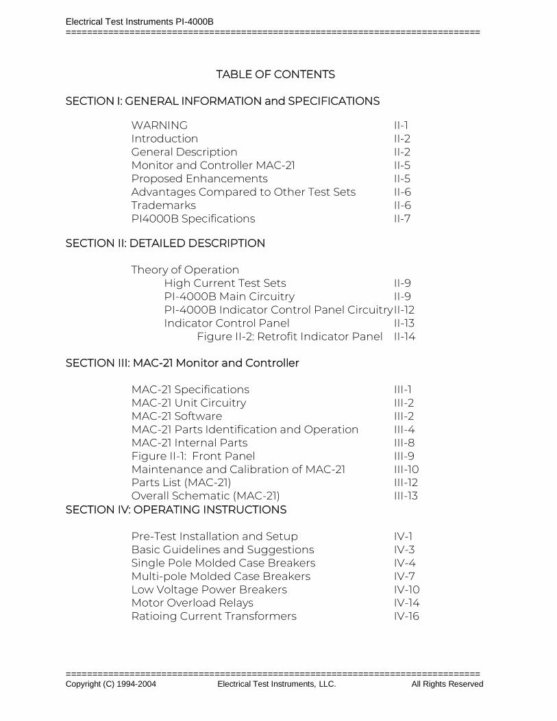
PRIMARY INJECTION CIRCUIT BREAKER TEST SET
INSTRUCTION MANUAL
Model
PI-4000B
Electrical Test Instruments, LLC. 1301 Avondale Road, Suite J
New Windsor, MD 21776
www.ETIPrecision.com
(410) 857-1880 Fax (410) 857-1387
Electrical Test Instruments PI-4000B ==============================================================================
============================================================================== Copyright (C) 1994-2004 Electrical Test Instruments, LLC. All Rights Reserved
TABLE OF CONTENTS SECTION I: GENERAL INFORMATION and SPECIFICATIONS WARNING II-1 Introduction II-2 General Description II-2 Monitor and Controller MAC-21 II-5 Proposed Enhancements II-5 Advantages Compared to Other Test Sets II-6 Trademarks II-6 PI4000B Specifications II-7 SECTION II: DETAILED DESCRIPTION Theory of Operation
High Current Test Sets II-9 PI-4000B Main Circuitry II-9 PI-4000B Indicator Control Panel Circuitry II-12
Indicator Control Panel II-13 Figure II-2: Retrofit Indicator Panel II-14 SECTION III: MAC-21 Monitor and Controller MAC-21 Specifications III-1 MAC-21 Unit Circuitry III-2 MAC-21 Software III-2 MAC-21 Parts Identification and Operation III-4 MAC-21 Internal Parts III-8 Figure II-1: Front Panel III-9 Maintenance and Calibration of MAC-21 III-10 Parts List (MAC-21) III-12 Overall Schematic (MAC-21) III-13 SECTION IV: OPERATING INSTRUCTIONS Pre-Test Installation and Setup IV-1 Basic Guidelines and Suggestions IV-3 Single Pole Molded Case Breakers IV-4 Multi-pole Molded Case Breakers IV-7 Low Voltage Power Breakers IV-10 Motor Overload Relays IV-14 Ratioing Current Transformers IV-16
Electrical Test Instruments PI-4000B ==============================================================================
============================================================================== Copyright (C) 1994-2004 Electrical Test Instruments, LLC. All Rights Reserved
SECTION V: SERVICE INFORMATION AND DOCUMENTATION Maintenance and Calibration of PI-4000B V-1 Maintenance and Calibration of MAC-21 V-1 Parts List (PI-4000B) V-4 Parts List (Indicator Control Panel) V-5 Parts List (MAC-21) V-6 Overall Schematic (PI-4000B) V-7 Overall Schematic (Indicator Control Panel) V-8 Warranty END Additional Schematics END
Electrical Test Instruments PI-4000B Section II – Detailed Description ==============================================================================
============================================================================== Copyright(C) 1994-2004 Electrical Test Instruments, LLC. All Rights Reserved
SECTION I
GENERAL INFORMATION
Electrical Test Instruments PI-4000B Section II - Detailed Description ==============================================================================
============================================================================== Copyright(C) 1994-2004 Electrical Test Instruments, LLC. All Rights Reserved Page II-1
SECTION I
GENERAL INFORMATION
WARNING
WARNING - READ THIS ENTIRE MANUAL AND THOROUGHLY FAMILIARIZE YOURSELF WITH THE UNIT OPERATION PRIOR TO CONNECTING THE UNIT TO A SOURCE OF POWER. HIGH CURRENT TEST SETS ARE NORMALLY POWERED FROM HIGH CAPACITY 208 VOLT TO 575 VOLT SERVICES, AND IMPROPER CONNECTION OR OPERATION COULD CAUSE DAMAGE TO THE TEST SET AND EQUIPMENT UNDER TEST, AS WELL AS CREATE AN UNSAFE CONDITION FOR PERSONS OPERATING THE SET.
Electrical Test Instruments PI-4000B Section II - Detailed Description ==============================================================================
============================================================================== Copyright(C) 1994-2004 Electrical Test Instruments, LLC. All Rights Reserved Page II-2
INTRODUCTION
A primary injection test set such as the PI-4000B is a device with high current, low voltage AC outputs for testing direct acting low voltage circuit breakers. Current is injected through the main contacts of the breaker to simulate actual fault conditions, which tests the operation of CTs, solid state, thermal, or electromechanical trip devices, and the actual trip mechanisms and breaker contacts.
GENERAL DESCRIPTION
The PI-4000B is a versatile and technologically advanced primary injection test set capable of testing circuit breakers up to 4000 amperes frame size. It incorporates an improved low impedance output transformer with dual primaries to facilitate its use on power sources of 480 VAC as well as 240 and 208 VAC, and dual secondaries to provide optimal impedance matching to a wide range of breaker sizes. High capacity internal fan cooling allows maximum utilization of the output transformer and faster recovery after overload conditions.
It is housed in a rugged steel enclosure with removable sides and top for easy access to internal components. The sides are clear of protruding components, and full-width handles with provisions for lifting hooks are on both ends. Locking swivel castors on all four corners provide ease of mobility.
The indicator control panel and MAC-21 are mounted in a compact hood with a hinged lid on the top, which provides maximum protection during transportation and a large flat area on the top surface for convenient placement of manuals, breaker curve books, and auxiliary instruments. A hinged access panel in the back of the hood provides a storage area for manuals, contact leads, fuses, and other small items. The auxiliary 120 VAC GFI protected outlet is conveniently located on the side of the hood, and protected by an 8-ampere circuit breaker.
The output stab plates accommodate standard breaker stab adaptors. The rugged silver-plated copper stab adaptors supplied with the test set are designed to be used for both vertical and horizontal stabs, and have both ½” and ¾” output plates. Standard ½”-13 stainless steel hex head bolts with matching nuts and washers are used to connect the output stab plates, and they may be replaced easily.
An optional series adaptor assembly allows the output to be configured for continuous current of 2000 amps at 22 VAC for testing breakers that require connection via cables. An automatic sensor adjusts the internal CT output for proper readings in either configuration.
The test set may be plugged into any 60 Hz AC voltage source of 200-250 VAC

Electrical Test Instruments PI-4000B Section II - Detailed Description ==============================================================================
============================================================================== Copyright(C) 1994-2004 Electrical Test Instruments, LLC. All Rights Reserved Page II-3
or 400-500 VAC, and will work on 50 Hz sources of 200-210 VAC or 400-420 VAC. The line voltage is displayed on the indicator control panel digital meter. An internal voltage sensor automatically configures the AC control power for nominal 240 or 480 VAC, and monitors input voltage for compliance to specifications. The main output section may be configured by means of a simple rotary switch on the power input panel, and an interlock allows the power section to be energized only when properly configured for the applied voltage.
The Vernier uses a large wheel to adjust the output manually within the range determined by the coarse tap, as well as a motorized control actuated by means of a smart control switch. When the switch is pressed briefly, the Vernier moves in a very small increment for fine control. When the switch is held, the Vernier moves very quickly, so that the entire span may be traversed in less than five seconds. The approximate Vernier position is displayed on an LED indicator bar graph. For the PI-4000B, the Vernier is always turned clockwise to increase output.
The electronically controlled tap selection uses power contactors to set the coarse tap. The unit powers up in the lowest tap position (1), and the setting may be adjusted by means of a rocker switch on the indicator/control panel. If the switch is held, the taps change at a rate of about one per second. Tap change is not allowed when output is on.
The indicator/control panel features two temperature indicators: one for the output bus temperature, and the other for the overall system temperature. This is determined by a combination of actual winding temperature, and a “virtual temperature” which is derived from time and current duty cycle usage as monitored by a “POD”, or Programmable Overload Device. Additional details are available in a separate manual. If either temperature exceeds a safe operating level, the interlock is asserted and the output section is de-energized. Additional thermostatic sensors in the output transformer windings will also assert the interlock if unsafe temperature levels are detected.
The output voltage of the test set is provided on the indicator/control panel for monitoring by means of a separate digital voltmeter.
Primary catastrophic overload protection for the test set is accomplished with input fuses having high interrupting current capacity. Overload of the output system is sensed by means of the previously mentioned “POD” on the Vernier autotransformer, and thermal sensors in each winding and on the SCR. The combination of these devices allows full utilization of the overload capability of the test set, and eliminates costly and cumbersome fuse replacement required in other test sets.
The output of the test set is controlled by means of a proven SCR controller. This provides precise initial phase angle control to reduce DC offset for inductive
Electrical Test Instruments PI-4000B Section II - Detailed Description ==============================================================================
============================================================================== Copyright(C) 1994-2004 Electrical Test Instruments, LLC. All Rights Reserved Page II-4
loads and more consistent pulse currents. The phase angle is internally adjustable.
The measurement of output current and time is accomplished by means of the proven MAC-21, which uses highly accurate A/D circuitry and intelligent firmware to resolve true-RMS values of distorted waveforms. It also provides features such as preset ON times for convenient jogging of output current without overheating the breaker or causing unwanted trips.
The entire test set has been designed for reliability, ruggedness, and ease of use. Sophisticated electronics in the indicator/control panel and the MAC-21 provide state of the art accuracy and convenience, while simple connections allow for easy removal and replacement for transportation or service. All covers are removable, allowing easy access to all internal components. A horizontal relay panel located just under the top panel contains most of the circuitry, facilitating service and maintenance. Two large front-mounted fans provide maximum airflow to the transformer and output bus, and rear exhaust directs air flow away from the operator. The cabinet is designed with no protruding components on the sides, so it can be navigated through narrow doorways without problems. The input jacks and voltage switch are protected by the heavy-duty full width handles on both ends.
Electrical Test Instruments PI-4000B Section II - Detailed Description ==============================================================================
============================================================================== Copyright(C) 1994-2004 Electrical Test Instruments, LLC. All Rights Reserved Page II-5
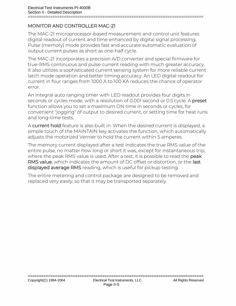
MONITOR AND CONTROLLER MAC-21
The MAC-21 microprocessor-based measurement and control unit features digital readout of current and time enhanced by digital signal processing. Pulse (memory) mode provides fast and accurate automatic evaluation of output current pulses as short as one-half cycle.
The MAC-21 incorporates a precision A/D converter and special firmware for true-RMS continuous and pulse current reading with much greater accuracy. It also utilizes a sophisticated current sensing system for more reliable current latch mode operation and better timing accuracy. An LED digital readout for current in four ranges from 1000 A to 100 KA reduces the chance of operator error.
An integral auto ranging timer with LED readout provides four digits in seconds or cycles mode, with a resolution of 0.001 second or 0.5 cycle. A preset function allows you to set a maximum ON time in seconds or cycles, for convenient "jogging" of output to desired current, or setting time for heat runs and long-time tests.
A current hold feature is also built in. When the desired current is displayed, a simple touch of the MAINTAIN key activates the function, which automatically adjusts the motorized Vernier to hold the current within 5 amperes.
The memory current displayed after a test indicates the true RMS value of the entire pulse, no matter how long or short it was, except for instantaneous trip, where the peak RMS value is used. After a test, it is possible to read the peak RMS value, which indicates the amount of DC offset or distortion, or the last displayed average RMS reading, which is useful for pickup testing.
The entire metering and control package are designed to be removed and replaced very easily, so that it may be transported separately.
Electrical Test Instruments PI-4000B Section II - Detailed Description ==============================================================================
============================================================================== Copyright(C) 1994-2004 Electrical Test Instruments, LLC. All Rights Reserved Page II-6
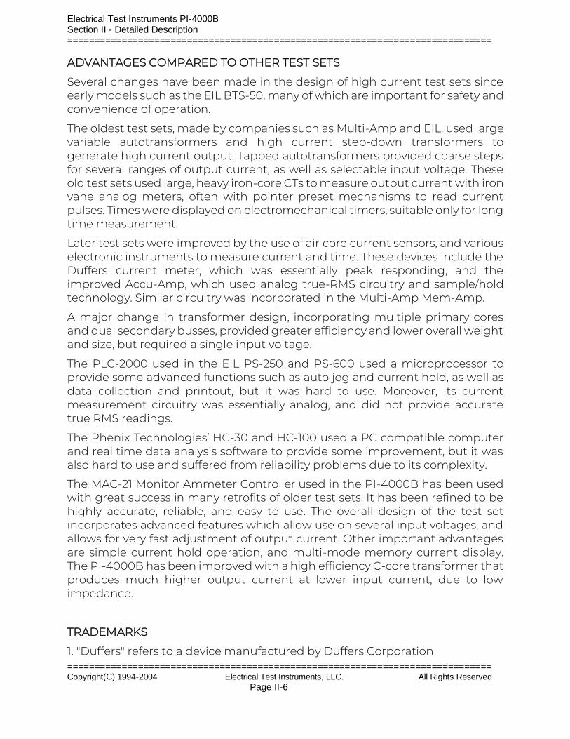
ADVANTAGES COMPARED TO OTHER TEST SETS
Several changes have been made in the design of high current test sets since early models such as the EIL BTS-50, many of which are important for safety and convenience of operation.
The oldest test sets, made by companies such as Multi-Amp and EIL, used large variable autotransformers and high current step-down transformers to generate high current output. Tapped autotransformers provided coarse steps for several ranges of output current, as well as selectable input voltage. These old test sets used large, heavy iron-core CTs to measure output current with iron vane analog meters, often with pointer preset mechanisms to read current pulses. Times were displayed on electromechanical timers, suitable only for long time measurement.
Later test sets were improved by the use of air core current sensors, and various electronic instruments to measure current and time. These devices include the Duffers current meter, which was essentially peak responding, and the improved Accu-Amp, which used analog true-RMS circuitry and sample/hold technology. Similar circuitry was incorporated in the Multi-Amp Mem-Amp.
A major change in transformer design, incorporating multiple primary cores and dual secondary busses, provided greater efficiency and lower overall weight and size, but required a single input voltage.
The PLC-2000 used in the EIL PS-250 and PS-600 used a microprocessor to provide some advanced functions such as auto jog and current hold, as well as data collection and printout, but it was hard to use. Moreover, its current measurement circuitry was essentially analog, and did not provide accurate true RMS readings.
The Phenix Technologies’ HC-30 and HC-100 used a PC compatible computer and real time data analysis software to provide some improvement, but it was also hard to use and suffered from reliability problems due to its complexity.
The MAC-21 Monitor Ammeter Controller used in the PI-4000B has been used with great success in many retrofits of older test sets. It has been refined to be highly accurate, reliable, and easy to use. The overall design of the test set incorporates advanced features which allow use on several input voltages, and allows for very fast adjustment of output current. Other important advantages are simple current hold operation, and multi-mode memory current display. The PI-4000B has been improved with a high efficiency C-core transformer that produces much higher output current at lower input current, due to low impedance.
TRADEMARKS
1. "Duffers" refers to a device manufactured by Duffers Corporation
Electrical Test Instruments PI-4000B Section II - Detailed Description ==============================================================================
============================================================================== Copyright(C) 1994-2004 Electrical Test Instruments, LLC. All Rights Reserved Page II-7
2. "Accu-Amp" is a trademark for a device originally made by EIL Instruments, Inc.
3. "SmartCore" is a trademark of ZWorld Engineering, Davis, CA.
Electrical Test Instruments PI-4000B Section II - Detailed Description ==============================================================================
============================================================================== Copyright(C) 1994-2004 Electrical Test Instruments, LLC. All Rights Reserved Page II-8
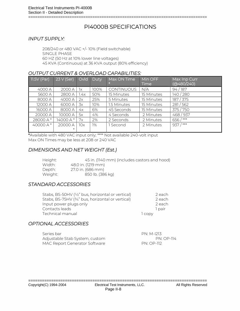
PI4000B SPECIFICATIONS INPUT SUPPLY: 208/240 or 480 VAC +/- 10% (Field switchable) SINGLE PHASE 60 HZ (50 Hz at 10% lower line voltages) 45 KVA (Continuous) at 36 KVA output (80% efficiency) OUTPUT CURRENT & OVERLOAD CAPABILITIES:
11.5V (Par) 23 V (Ser) Ovld Duty Max ON Time *
Min OFF Time
Max Inp Curr (@480/240)
4000 A 2000 A 1x 100% CONTINUOUS N/A 94 / 187 5600 A 2800 A 1.4x 50% 15 Minutes 15 Minutes 140 / 280 8000 A 4000 A 2x 25% 5 Minutes 15 Minutes 187 / 375
12000 A 6000 A 3x 10% 1.5 Minutes 15 Minutes 281 / 562 16000 A 8000 A 4x 6% 45 Seconds 15 Minutes 375 / 750
20000 A 10000 A 5x 4% 4 Seconds 2 Minutes 468 / 937 28000 A * 14000 A * 7x 2% 2 Seconds 2 Minutes 656 / *** 40000 A * 20000 A
* 10x 1% 1 Second 2 Minutes 937 / ***
*Available with 480 VAC input only; **** Not available 240-volt input Max ON Times may be less at 208 or 240 VAC DIMENSIONS AND NET WEIGHT (Est.) Height: 45 in. (1140 mm) (includes castors and hood) Width: 48.0 in. (1219 mm) Depth: 27.0 in. (686 mm) Weight: 850 lb. (386 kg) STANDARD ACCESSORIES Stabs, BS-50HV (½” bus, horizontal or vertical) 2 each Stabs, BS-75HV (¾” bus, horizontal or vertical) 2 each Input power plugs only 2 each Contacts leads 1 pair Technical manual 1 copy OPTIONAL ACCESSORIES Series bar PN: M-I213 Adjustable Stab System, custom PN: OP-114 MAC Report Generator Software PN: OP-112
Electrical Test Instruments PI-4000B Section II - Detailed Description ==============================================================================
============================================================================== Copyright(C) 1994-2004 Electrical Test Instruments, LLC. All Rights Reserved Page II-9
SECTION II DETAILED DESCRIPTION
Electrical Test Instruments PI-4000B Section II - Detailed Description ==============================================================================
============================================================================== Copyright(C) 1994-2004 Electrical Test Instruments, LLC. All Rights Reserved Page II-10
SECTION II
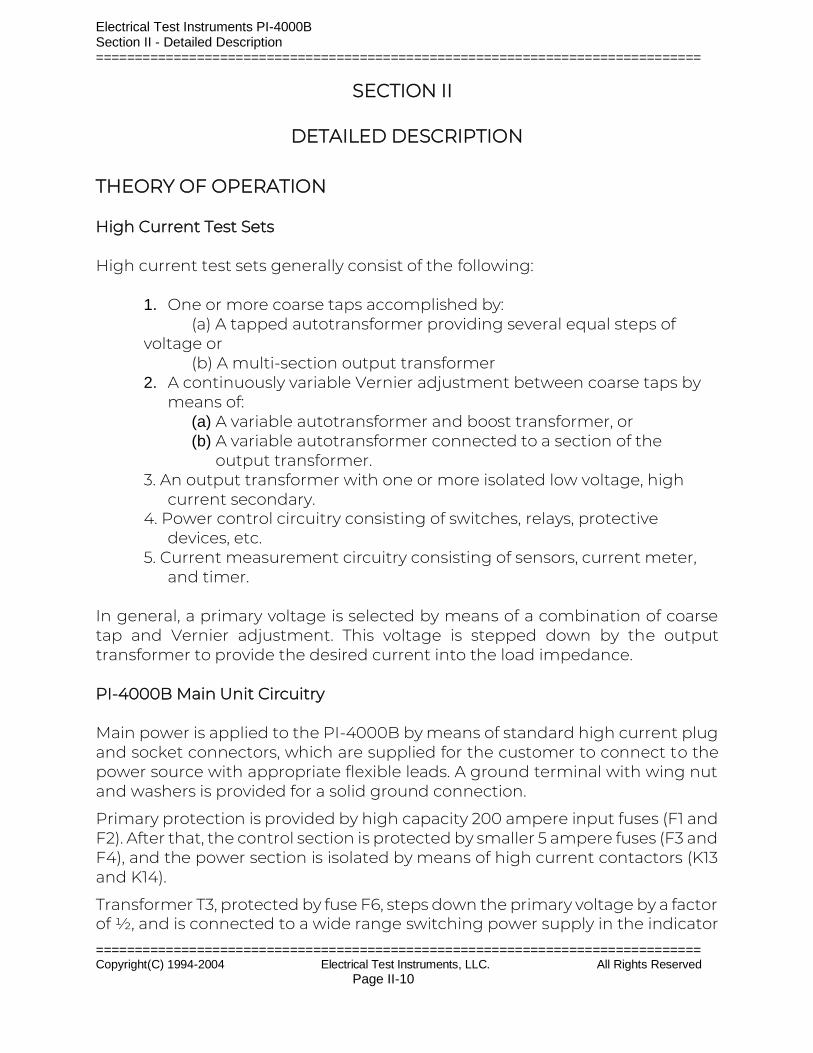
DETAILED DESCRIPTION THEORY OF OPERATION High Current Test Sets High current test sets generally consist of the following:
1. One or more coarse taps accomplished by: (a) A tapped autotransformer providing several equal steps of
voltage or (b) A multi-section output transformer
2. A continuously variable Vernier adjustment between coarse taps by means of:
(a) A variable autotransformer and boost transformer, or (b) A variable autotransformer connected to a section of the
output transformer. 3. An output transformer with one or more isolated low voltage, high
current secondary. 4. Power control circuitry consisting of switches, relays, protective
devices, etc. 5. Current measurement circuitry consisting of sensors, current meter,
and timer. In general, a primary voltage is selected by means of a combination of coarse tap and Vernier adjustment. This voltage is stepped down by the output transformer to provide the desired current into the load impedance. PI-4000B Main Unit Circuitry Main power is applied to the PI-4000B by means of standard high current plug and socket connectors, which are supplied for the customer to connect to the power source with appropriate flexible leads. A ground terminal with wing nut and washers is provided for a solid ground connection.
Primary protection is provided by high capacity 200 ampere input fuses (F1 and F2). After that, the control section is protected by smaller 5 ampere fuses (F3 and F4), and the power section is isolated by means of high current contactors (K13 and K14).
Transformer T3, protected by fuse F6, steps down the primary voltage by a factor of ½, and is connected to a wide range switching power supply in the indicator

Electrical Test Instruments PI-4000B Section II - Detailed Description ==============================================================================
============================================================================== Copyright(C) 1994-2004 Electrical Test Instruments, LLC. All Rights Reserved Page II-11
control panel to provide 12 VDC. Transformer T6, protected by fuse F5, steps it down by a factor of ¼, and this voltage is sensed by a voltage relay circuit. When the primary voltage is between about 200 and 270 VAC, this circuit allows operation in 240 VAC mode. If the voltage is between about 420 and 520 VAC, operation is allowed in 480 VAC mode. Control power cannot be turned on if the voltage is outside these bounds.
When the input voltage selector switch S11 is the 208/240 V position, relay K9 is energized, setting the primary windings of transformer T4 in parallel. This also energizes relay K1 on the voltage sensor PCB, and provides an interlock and input selector error indication. The voltage sensor PCB rapidly flashes the Input Select Error LED on the control panel for 5 seconds during startup, and then turns off if input voltage is within bounds as determined by the input selector switch position. If line voltage is incorrect, the Input Select Error LED will flash, and control power cannot be turned on. If control power is energized, brief voltage sags or surges will flash the LED as a warning. If such voltage excursions persist for longer than about 0.2 seconds, the control power will drop out.
Binding post BP1 is provided for separate connection to an earth ground, to check for ground integrity. When there is continuity from this point to chassis ground, relay K2 on the voltage sensor PCB is energized, and enables the interlock for control power. If ground integrity is not sensed, the Ground Open LED DS1 will light. A separate lead should be connected to the external equipment ground system to verify that the main grounding cable is intact. Do not defeat this safety feature by jumpering the ground binding post to the test set frame.
When the control power switch in the indicator control panel is pressed, and all voltage interlocks are OK, relay K10 is energized, which provides 120 VAC control power to the entire test set, including the fans and the auxiliary GFI outlet, protected by 8 ampere circuit breaker CB1.
If all power interlocks are OK, the Main Power switch in the indicator control panel may be pressed to activate main contactors K13-14. This provides high current power to the test set output circuitry through the SCR controller. The switched output voltage is supplied to distribution blocks DB1 and DB2.
The Vernier autotransformer T1 and output transformer T2 are connected to input voltage selector switch S11. This allows for connection in series for 480 VAC, and parallel for 208/240 VAC. Vernier T1 is connected directly to the first primary of T2, so that clockwise rotation produces an output voltage of about 0-1.5 VAC. Relays K1, K2, and K3 connect the second primary windings for fixed outputs of 0, 1.25, or 2.50 VAC for taps 1, 2 and 3. For subsequent taps, the large sections T2C, T2D, and T2E are added to the circuit, while the second section alternates between 1.25 and 2.5 VAC, for a series of nine (9) overlapping output ranges up to 11.5 VAC.

Electrical Test Instruments PI-4000B Section II - Detailed Description ==============================================================================
============================================================================== Copyright(C) 1994-2004 Electrical Test Instruments, LLC. All Rights Reserved Page II-12
Output current is detected by means of an air core CT around both main busses. When the series bar is attached to the output, a switch is actuated, which divides the signal by a factor of 2. Calibration of series and parallel modes is accomplished with potentiometers on the S/P calibration/switch assembly under the output face plate.
The output section is energized when a signal is applied to the trigger board of the SCR controller. The initial phase angle is determined by a zero-crossing detector in the trigger PCB, and a delay which is normally preset to 70 degrees.
The Vernier autotransformer may be adjusted manually by means of a handwheel, or by activating the motor drive. Increasing output is clockwise for all taps.
When T1 is energized, 120 VAC is applied to the primary of T5. This provides a voltage of about 12 VAC which is used for output ON detection in the indicator control panel.
Thermistor TH1 senses the temperature of the output bus, and TH2 reads the temperature of the first primary of T2. These normally have a resistance of 10 K ohms at room temperature, and lower values as the temperature increases.
Relays K1 through K6 are energized through the indicator control panel. Relays K1, K2, and K3 are equipped with a electrical interlocks to avoid damage if all three are simultaneously energized. Catastrophic protection is provided by fuses F7 through F16.
The adjustable Vernier assembly in the PI-4000B consists of a stack of four 120 VAC decks, with each series connected pair connected to a 240 VAC primary on T2A. Minor voltage imbalance up to about 2 VAC is corrected by means of paralleling transformer T7, and actual current in each primary circuit is monitored by means of 50:5 current transformers T10 and T11. Resistors R1 through R4 ensure voltage balance on the series connected pairs, and also provide a resistive load to stabilize the SCR controller at low output settings.
The secondary currents from T10 and T11 are monitored by the Programmable Overload Monitor (POD), which also measures actual temperature in the primary winding of T2A. The overall system status is displayed on the bar graph of the indicator control panel, and an interlock relay shuts down the output of the test set if abnormal conditions are detected. More details are in a separate manual.
The voltage on the coil of interlock relays K13 and K14 is monitored by interlock detector relay K7. If the voltage drops to a point where the relays would drop out, this module turns off the signal to the SCR trigger board, so as to turn off main output current before the interlock relays actually open.
The PI-4000B features a very efficient low impedance output transformer with enhanced reliability and cooler operation due to output plates brazed directly
Electrical Test Instruments PI-4000B Section II - Detailed Description ==============================================================================
============================================================================== Copyright(C) 1994-2004 Electrical Test Instruments, LLC. All Rights Reserved Page II-13
to the secondary bus conductors. The high strength and corrosion resistant stainless-steel output bolts should rarely require replacement, but may be serviced by simply removing the sixteen screws on the phenolic output faceplate, and then removing one of four bolt retainers. The standard hex head bolts may then be pushed through and replaced. The bolt retainers for the upper bolts in the lower plates are also the air core CTs.

Electrical Test Instruments PI-4000B Section II - Detailed Description ==============================================================================
============================================================================== Copyright(C) 1994-2004 Electrical Test Instruments, LLC. All Rights Reserved Page II-14
PI-4000 Indicator Control Panel Circuitry
The power for the control panel is provided by the INV/2 circuit, which is the main input voltage divided by 2. This voltage, ranging from 104 VAC to 240 VAC, powers a wide range switching power supply, which supplies 12 VDC to the rest of the circuitry. When the CTL ON switch S1 is pressed, DS1 lights and relay K4 is energized, and latches on if voltage interlocks are OK and the external control relay energizes. K4 also provides 12 VDC power to the PC board, which has circuitry for Vernier position display and adjustment, tap selection and display, and temperature readings. Pressing S2 turns control power off.
If any external interlock is open, as sensed by K1, indicator DS4 will light. Otherwise, K2 will energize, which energizes K2 and allow operation of S3. When MAIN ON switch S3 is pressed, relay K3 energizes, MAIN READY lamp DS3 lights, and power is provided to external main contactor. If it operates, K3 is latched on through its auxiliary contact.
If the output of the test set is ON, 12 VAC will be applied to DS5, and also will be sensed by the PC board, which will inhibit tap change.
The INV/4A and B signals provide a voltage equal to ¼ the input voltage. This is rectified and filtered by the metering PC board, and displayed on the panel meter.
Output is inhibited during tap change or when an interlock condition exists. An interlock (INTLKB) will be asserted if either temperature readouts exceed an adjusted setpoint.
The Vernier position signal is supplied to the PC board, and displayed as a 0-100% reading on a ten segment LED bar graph. The signal is about 1.0 to 4.0 VDC.
The bus temperature is from a 10 K ohm thermistor. System temperature is a variable voltage from the POD, as discussed elsewhere. Circuitry in the PC board converts these signals to voltages which are displayed on multicolor bar graphs. When the signal exceeds that which lights one red bar, the interlock is tripped.
The output voltage of the test set is supplied at binding posts BP1 and BP2.
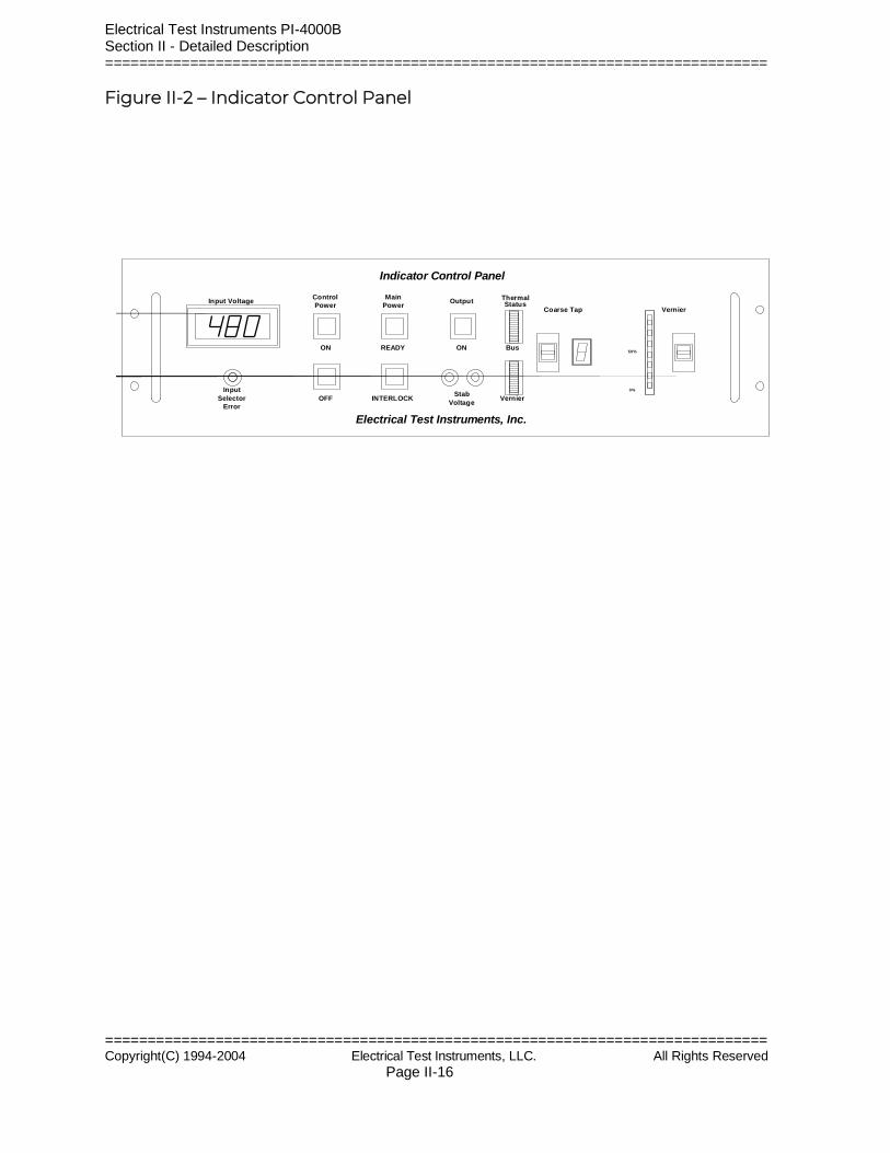
Indicator Control Panel
Input Voltage Meter: This LED panel meter indicates the approximate input voltage applied to the test set.
Control Power ON switch: This green switch turns on 120 VAC control power to the test set, and its green lamp lights when ON.
Control Power OFF switch: This red switch turns off the 120 VAC control power to the test set.

Electrical Test Instruments PI-4000B Section II - Detailed Description ==============================================================================
============================================================================== Copyright(C) 1994-2004 Electrical Test Instruments, LLC. All Rights Reserved Page II-15
Main Power READY switch: This green switch turns on the main power to the output section of the test set, and its green lamp lights when ON.
Main Power INTERLOCK switch: This red switch turns off the main power to the test set. It lights if an interlock condition is detected.
Output ON indicator: This yellow lamp lights when output voltage is ON.
Output Voltage binding posts: These binding posts are connected to output stabs 1 and 4, and may be used to monitor voltage on the breaker with a DMM.
Thermal Status - Bus: This multicolor bar graph indicates approximate temperature of the output bus. Green bars indicate normal temperature. Yellow bars indicate significant heating, and heavy testing should be postponed until unit cools. Red bars indicate overheating, and unit must cool to yellow range before testing. Output initiation will be inhibited if second red bar lights. Excessive temperature may indicate poor output connections.
Thermal Status - System: This indicates temperature of the output section, and other conditions, as determined by the POD. A thermistor in the winding of the first section of the output transformer provides actual temperature, but the POD also calculates a “virtual” temperature based on overload duty cycle limits as indicated in the specifications. The ten bar graph LEDs correspond to temperatures of approximately 80 to 280 degrees F, with about 20 degrees per bar. Testing is allowed up to a reading of two red bars, but will then be inhibited until temperature cools to no more than four yellow bars.
Coarse Tap Switch: This rocker switch selects the coarse tap. The unit powers up in tap 1. Pressing the switch briefly UP or DOWN will raise or lower the tap by one. Holding it will change taps about one per second.
Coarse Tap Indicator: This seven-segment red LED indicates tap position from 1 to 9.
Vernier Indicator Bar graph: This ten-segment red LED indicates approximate Vernier position. 0 or 1 segment lit indicates minimum position, and 9 or 10 segments lit indicates maximum position.
Vernier Adjust Switch: This rocker switch adjusts the Vernier position. Pressing it briefly UP or DOWN causes the Vernier to move by a very small increment, for fine control. Holding it for about a second will cause the Vernier to move very quickly, for rapid rough adjustment.
Electrical Test Instruments PI-4000B Section II - Detailed Description ==============================================================================
============================================================================== Copyright(C) 1994-2004 Electrical Test Instruments, LLC. All Rights Reserved Page II-16
Figure II-2 – Indicator Control Panel
ThermalStatus
Bus
Vernier
Up
Down
Up
Down
ON
Stab
Voltage
READY
INTERLOCK
ON
OFF
OutputMainControl
Coarse Tap VernierPower
Input Voltage
0%
50%
100%
Electrical Test Instruments, Inc.
Indicator Control Panel
Power
Input
Selector
Error

Electrical Test Instruments PI-4000B Section II – Detailed Description ==============================================================================
============================================================================== Copyright(C) 1994-2004 Electrical Test Instruments, LLC. All Rights Reserved
MEMORY AMMETER CONTROLLER MAC-21
INSTRUCTION MANUAL Firmware Version 3.06 and above
Electrical Test Instruments, LLC 1301 Avondale Road, Suite J
Electrical Test Instruments MAC-21 Section III – MAC-21 ==============================================================================
============================================================================== Copyright(C) 1994-2004 Electrical Test Instruments, LLC All Rights Reserved Page III-1
New Windsor, MD 21776 www.ETIPrecision.com
(410) 857-1880
Fax (410) 857-1387
Electrical Test Instruments MAC-21 Section III – MAC-21 ==============================================================================
============================================================================== Copyright(C) 1994-2004 Electrical Test Instruments, LLC All Rights Reserved Page III-2
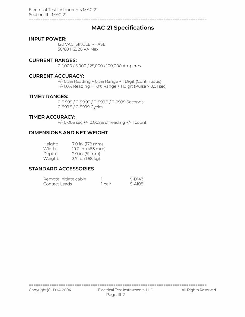
MAC-21 Specifications INPUT POWER: 120 VAC, SINGLE PHASE 50/60 HZ, 20 VA Max
CURRENT RANGES: 0-1,000 / 5,000 / 25,000 / 100,000 Amperes CURRENT ACCURACY: +/- 0.5% Reading + 0.5% Range + 1 Digit (Continuous) +/- 1.0% Reading + 1.0% Range + 1 Digit (Pulse > 0.01 sec) TIMER RANGES: 0-9.999 / 0-99.99 / 0-999.9 / 0-9999 Seconds 0-999.9 / 0-9999 Cycles TIMER ACCURACY: +/- 0.005 sec +/- 0.005% of reading +/- 1 count DIMENSIONS AND NET WEIGHT Height: 7.0 in. (178 mm) Width: 19.0 in. (483 mm) Depth: 2.0 in. (51 mm) Weight: 3.7 lb. (1.68 kg) STANDARD ACCESSORIES Remote Initiate cable 1 S-B143
Contact Leads 1 pair S-A108
Electrical Test Instruments MAC-21 Section III – MAC-21 ==============================================================================
============================================================================== Copyright(C) 1994-2004 Electrical Test Instruments, LLC All Rights Reserved Page III-3
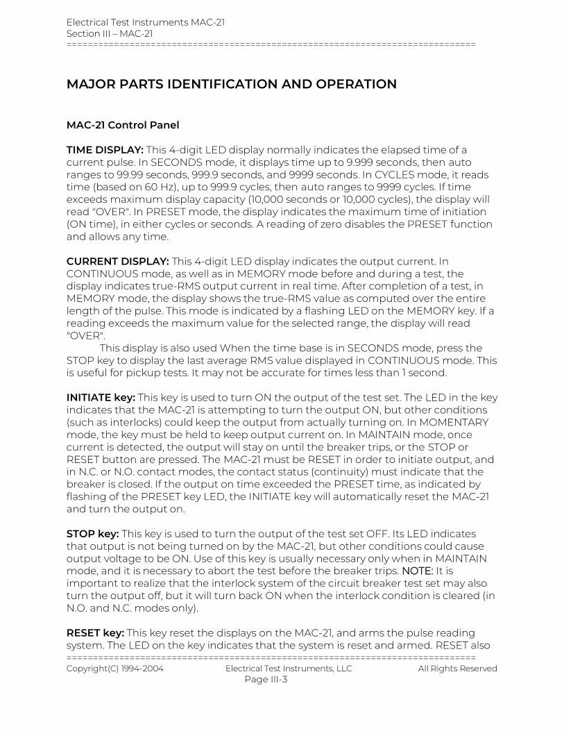
MAJOR PARTS IDENTIFICATION AND OPERATION MAC-21 Control Panel TIME DISPLAY: This 4-digit LED display normally indicates the elapsed time of a current pulse. In SECONDS mode, it displays time up to 9.999 seconds, then auto ranges to 99.99 seconds, 999.9 seconds, and 9999 seconds. In CYCLES mode, it reads time (based on 60 Hz), up to 999.9 cycles, then auto ranges to 9999 cycles. If time exceeds maximum display capacity (10,000 seconds or 10,000 cycles), the display will read "OVER". In PRESET mode, the display indicates the maximum time of initiation (ON time), in either cycles or seconds. A reading of zero disables the PRESET function and allows any time. CURRENT DISPLAY: This 4-digit LED display indicates the output current. In CONTINUOUS mode, as well as in MEMORY mode before and during a test, the display indicates true-RMS output current in real time. After completion of a test, in MEMORY mode, the display shows the true-RMS value as computed over the entire length of the pulse. This mode is indicated by a flashing LED on the MEMORY key. If a reading exceeds the maximum value for the selected range, the display will read "OVER". This display is also used When the time base is in SECONDS mode, press the STOP key to display the last average RMS value displayed in CONTINUOUS mode. This is useful for pickup tests. It may not be accurate for times less than 1 second. INITIATE key: This key is used to turn ON the output of the test set. The LED in the key indicates that the MAC-21 is attempting to turn the output ON, but other conditions (such as interlocks) could keep the output from actually turning on. In MOMENTARY mode, the key must be held to keep output current on. In MAINTAIN mode, once current is detected, the output will stay on until the breaker trips, or the STOP or RESET button are pressed. The MAC-21 must be RESET in order to initiate output, and in N.C. or N.O. contact modes, the contact status (continuity) must indicate that the breaker is closed. If the output on time exceeded the PRESET time, as indicated by flashing of the PRESET key LED, the INITIATE key will automatically reset the MAC-21 and turn the output on. STOP key: This key is used to turn the output of the test set OFF. Its LED indicates that output is not being turned on by the MAC-21, but other conditions could cause output voltage to be ON. Use of this key is usually necessary only when in MAINTAIN mode, and it is necessary to abort the test before the breaker trips. NOTE: It is important to realize that the interlock system of the circuit breaker test set may also turn the output off, but it will turn back ON when the interlock condition is cleared (in N.O. and N.C. modes only). RESET key: This key reset the displays on the MAC-21, and arms the pulse reading system. The LED on the key indicates that the system is reset and armed. RESET also
Electrical Test Instruments MAC-21 Section III – MAC-21 ==============================================================================
============================================================================== Copyright(C) 1994-2004 Electrical Test Instruments, LLC All Rights Reserved Page III-4
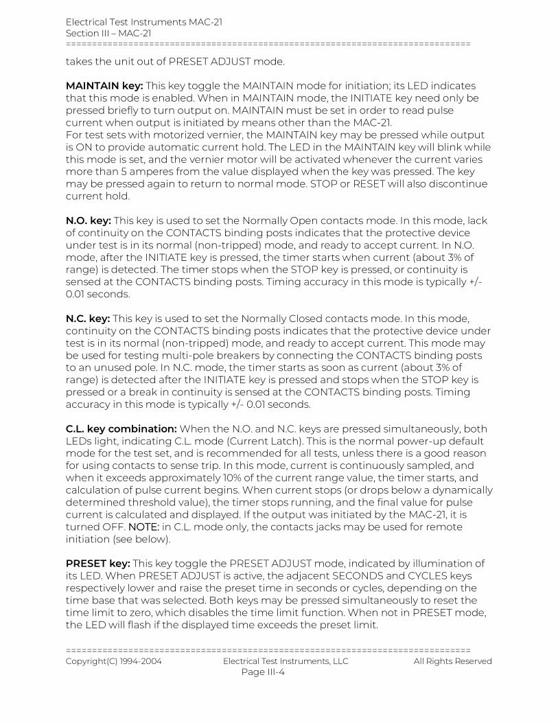
takes the unit out of PRESET ADJUST mode. MAINTAIN key: This key toggle the MAINTAIN mode for initiation; its LED indicates that this mode is enabled. When in MAINTAIN mode, the INITIATE key need only be pressed briefly to turn output on. MAINTAIN must be set in order to read pulse current when output is initiated by means other than the MAC-21. For test sets with motorized vernier, the MAINTAIN key may be pressed while output is ON to provide automatic current hold. The LED in the MAINTAIN key will blink while this mode is set, and the vernier motor will be activated whenever the current varies more than 5 amperes from the value displayed when the key was pressed. The key may be pressed again to return to normal mode. STOP or RESET will also discontinue current hold. N.O. key: This key is used to set the Normally Open contacts mode. In this mode, lack of continuity on the CONTACTS binding posts indicates that the protective device under test is in its normal (non-tripped) mode, and ready to accept current. In N.O. mode, after the INITIATE key is pressed, the timer starts when current (about 3% of range) is detected. The timer stops when the STOP key is pressed, or continuity is sensed at the CONTACTS binding posts. Timing accuracy in this mode is typically +/- 0.01 seconds. N.C. key: This key is used to set the Normally Closed contacts mode. In this mode, continuity on the CONTACTS binding posts indicates that the protective device under test is in its normal (non-tripped) mode, and ready to accept current. This mode may be used for testing multi-pole breakers by connecting the CONTACTS binding posts to an unused pole. In N.C. mode, the timer starts as soon as current (about 3% of range) is detected after the INITIATE key is pressed and stops when the STOP key is pressed or a break in continuity is sensed at the CONTACTS binding posts. Timing accuracy in this mode is typically +/- 0.01 seconds. C.L. key combination: When the N.O. and N.C. keys are pressed simultaneously, both LEDs light, indicating C.L. mode (Current Latch). This is the normal power-up default mode for the test set, and is recommended for all tests, unless there is a good reason for using contacts to sense trip. In this mode, current is continuously sampled, and when it exceeds approximately 10% of the current range value, the timer starts, and calculation of pulse current begins. When current stops (or drops below a dynamically determined threshold value), the timer stops running, and the final value for pulse current is calculated and displayed. If the output was initiated by the MAC-21, it is turned OFF. NOTE: in C.L. mode only, the contacts jacks may be used for remote initiation (see below). PRESET key: This key toggle the PRESET ADJUST mode, indicated by illumination of its LED. When PRESET ADJUST is active, the adjacent SECONDS and CYCLES keys respectively lower and raise the preset time in seconds or cycles, depending on the time base that was selected. Both keys may be pressed simultaneously to reset the time limit to zero, which disables the time limit function. When not in PRESET mode, the LED will flash if the displayed time exceeds the preset limit.
Electrical Test Instruments MAC-21 Section III – MAC-21 ==============================================================================
============================================================================== Copyright(C) 1994-2004 Electrical Test Instruments, LLC All Rights Reserved Page III-5
SECONDS key: This key normally selects the SECONDS time base. If the PRESET mode is selected, this key is used to LOWER the preset time limit by decrements of 1.000 second (5.000 seconds above 10.00) with the SECONDS time base, or 1.0 cycles with the CYCLES time base. If it is held, the reading will decrease at a rate of about 5 intervals per second. If a preset time limit was set in SECONDS mode, the output will be turned off within 200 milliseconds of the limit. SECONDS or CYCLES time base may be selected at any time before, during, or after a test. CYCLES key: This key normally selects the CYCLES time base. If the PRESET mode is selected, this key is used to RAISE the preset time limit by increments of 1.000 seconds (5.000 seconds above 10.00) with the SECONDS time base, or 1.0 cycles with the CYCLES time base. If it is held, the reading will increase at a rate of about 5 intervals per second. If a preset time limit was set in CYCLES mode, the output will be turned off within several milliseconds after the limit has been reached. SECONDS or CYCLES time base may be selected at any time before, during, or after a test. MEMORY key: This key toggle the MEMORY mode, indicated by illumination of its LED. When in CONTINUOUS mode (LED off), the current display always reads the real-time continuous output current of the test set. In MEMORY mode (LED on), the current display will read the continuous output current until the test is complete. At this time, the LED will flash, and the display will read the computed true-RMS value of the entire current pulse for the duration indicated on the TIME display. This key may be pressed at any time before, during, or after the test, to toggle between the two modes. As described above, pressing the STOP key provides access to display of peak RMS and last average RMS current. 1000 A range key: This key selects the 1000 ampere range, which provides best accuracy of readings up to about 1000 amperes. Nominal currents close to this limit, when applied to the device under test, will sometimes cause higher peak currents, causing the display to read "OVER", indicating an overrange condition. If this happens, select the next higher range. Pressing any range switch will also RESET the MAC-21. 5 KA range key: This key selects the 5.000 KA range, for output currents up to about 5,000 amperes. See above for information common to all ranges. 25 KA range key: This key selects the 25.00 KA range, for output currents up to about 25,000 amperes. See above for information common to all ranges. 100 KA range key: This key selects the 100.0 KA range, for output currents up to about 100,000 amperes. See above for information common to all ranges. CONTINUITY lamp: This LED lights when continuity is detected at the CONTACTS binding posts in N.O. and N.C. modes. The beeper will also sound whenever contacts change state. CONTACTS/REMOTE jacks: These jacks provide a low-power AC signal which detects continuity in N.O. and N.C. modes, or is used with a pushbutton cord switch for
Electrical Test Instruments MAC-21 Section III – MAC-21 ==============================================================================
============================================================================== Copyright(C) 1994-2004 Electrical Test Instruments, LLC All Rights Reserved Page III-6
remote initiate function (see below). A resistance of about 200 ohms or less will be interpreted as continuity. Although the signal is low power and transformer isolated, it is good practice to avoid touching any conductive surface connected to these terminals. CAUTION: NEVER CONNECT THESE TERMINALS TO ANY LIVE CIRCUIT! REMOTE INITIATE: In C.L. mode only, the CONTACTS jacks provide a remote initiate function. For safety reasons, this function is disabled in MAINTAIN mode, unless a preset value is set in CYCLES time base. SERIAL port: This standard serial port may be connected to a printer, computer, or other device to print or store time and current values of test results in ASCII format. It is set for 9600 baud, 8 bits, 1 stop bit, no parity, no flow control. This information is sent at the end of each test, or by pressing the Stop and Reset keys. Report Generator Software Option: we also offer a software package for a Windows based computer that takes the data from the serial port and inserts time and current values into an excel document. Must have Microsoft office installed for this software to function properly. This can be custom tailored to Your excel document or use the generic document that is provided with the software
Electrical Test Instruments MAC-21 Section III – MAC-21 ==============================================================================
============================================================================== Copyright(C) 1994-2004 Electrical Test Instruments, LLC All Rights Reserved Page III-7
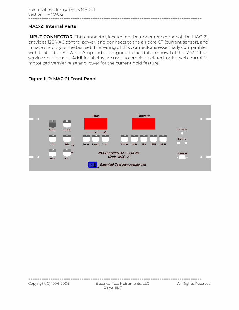
MAC-21 Internal Parts INPUT CONNECTOR: This connector, located on the upper rear corner of the MAC-21, provides 120 VAC control power, and connects to the air core CT (current sensor), and initiate circuitry of the test set. The wiring of this connector is essentially compatible with that of the EIL Accu-Amp and is designed to facilitate removal of the MAC-21 for service or shipment. Additional pins are used to provide isolated logic level control for motorized vernier raise and lower for the current hold feature. Figure II-2: MAC-21 Front Panel
Electrical Test Instruments MAC-21 Section III – MAC-21 ==============================================================================
============================================================================== Copyright(C) 1994-2004 Electrical Test Instruments, LLC All Rights Reserved Page III-8
SERVICE INFORMATION AND DOCUMENTATION MAINTENANCE AND CALIBRATION OF THE MAC-21 The MAC-21 is manufactured using solid state components that should not require extensive maintenance. However, the accuracy of the MAC-21 is critical to the testing of circuit breakers and is dependent upon the output of an air-core current sensing coil, which could change due to movement caused by shock or vibration encountered in transporting the test set. Other factors which may affect calibration are contact resistance in the control cable, unusual magnetic fields, insulation leakage, and aging of electronic components in the MAC-21. Therefore, proper operation and calibration should be checked at regular intervals and adjusted if proper equipment is available. The inherently delicate nature of electronic circuitry and metering make it generally inadvisable to leave the MAC-21 fastened into the breaker test set while it is being transported, and subject to shock and vibration. The standard rack-mount hardware and twist-lock connector make it simple to remove the MAC-21 and carry it separately.
Field calibration of the MAC-21 may be performed as follows: 1. Obtain a current measuring calibration standard capable of reading TRUE-
RMS current up to at least 1000 Amperes to an accuracy of at least 0.25%. This may consist of a shunt or current transformer, in conjunction with a digital multimeter or laboratory grade AC ammeter.
2. Set up the breaker test set for normal breaker testing. If adjustments are anticipated, remove the MAC-21 from the test set.
3. Connect the calibration standard to the desired output tap. If cables are used, it is recommended that they be twisted so as to minimize radiation and pickup of stray magnetic fields.
4. Apply power to test set and allow at least one minute for circuits to stabilize.
5. Check ammeter zero in all ranges. If reading on current meter is greater than 1% of range, internal zero adjustment may be required.
6. Set MAC-21 Range to 1000 A and adjust output of breaker test set to exactly 800 Amperes. If Coarse Tap is 1, and Output Control Vernier is less than 50%, additional resistance must be added to output circuit. This is
Electrical Test Instruments MAC-21 Section III – MAC-21 ==============================================================================
============================================================================== Copyright(C) 1994-2004 Electrical Test Instruments, LLC All Rights Reserved Page III-9
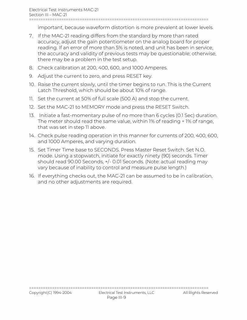
important, because waveform distortion is more prevalent at lower levels.
7. If the MAC-21 reading differs from the standard by more than rated accuracy, adjust the gain potentiometer on the analog board for proper reading. If an error of more than 5% is noted, and unit has been in service, the accuracy and validity of previous tests may be questionable; otherwise, there may be a problem in the test setup.
8. Check calibration at 200, 400, 600, and 1000 Amperes.
9. Adjust the current to zero, and press RESET key.
10. Raise the current slowly, until the timer begins to run. This is the Current Latch Threshold, which should be about 10% of range.
11. Set the current at 50% of full scale (500 A) and stop the current.
12. Set the MAC-21 to MEMORY mode and press the RESET Switch.
13. Initiate a fast-momentary pulse of no more than 6 cycles (0.1 Sec) duration. The meter should read the same value, within 1% of reading + 1% of range, that was set in step 11 above.
14. Check pulse reading operation in this manner for currents of 200, 400, 600, and 1000 Amperes, and varying duration.
15. Set Timer Time base to SECONDS. Press Master Reset Switch. Set N.O. mode. Using a stopwatch, initiate for exactly ninety (90) seconds. Timer should read 90.00 Seconds, +/- 0.01 Seconds. (Note: actual reading may vary because of inability to control and measure pulse length.)
16. If everything checks out, the MAC-21 can be assumed to be in calibration, and no other adjustments are required.
Electrical Test Instruments MAC-21 Section III – MAC-21 ==============================================================================
============================================================================== Copyright(C) 1994-2004 Electrical Test Instruments, LLC All Rights Reserved Page III-10
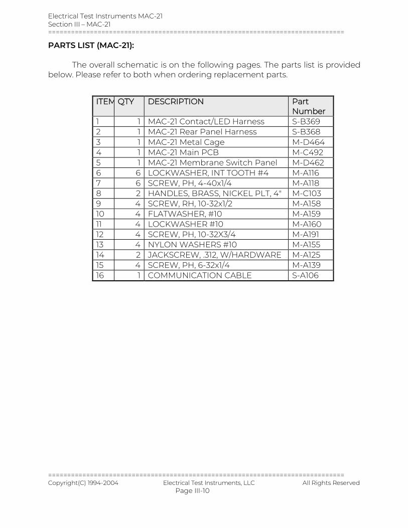
PARTS LIST (MAC-21): The overall schematic is on the following pages. The parts list is provided below. Please refer to both when ordering replacement parts.
ITEM QTY DESCRIPTION Part Number
1 1 MAC-21 Contact/LED Harness S-B369 2 1 MAC-21 Rear Panel Harness S-B368 3 1 MAC-21 Metal Cage M-D464 4 1 MAC-21 Main PCB M-C492 5 1 MAC-21 Membrane Switch Panel M-D462 6 6 LOCKWASHER, INT TOOTH #4 M-A116 7 6 SCREW, PH, 4-40x1/4 M-A118 8 2 HANDLES, BRASS, NICKEL PLT, 4" M-C103 9 4 SCREW, RH, 10-32x1/2 M-A158 10 4 FLATWASHER, #10 M-A159 11 4 LOCKWASHER #10 M-A160 12 4 SCREW, PH, 10-32X3/4 M-A191 13 4 NYLON WASHERS #10 M-A155 14 2 JACKSCREW, .312, W/HARDWARE M-A125 15 4 SCREW, PH, 6-32x1/4 M-A139 16 1 COMMUNICATION CABLE S-A106
Electrical Test Instruments MAC-21 Retrofit Package Section III – MAC-21 ===============================================================================================================
============================================================================================================= Copyright(C) 1994-2003 Electrical Test Instruments, LLC All Rights Reserved
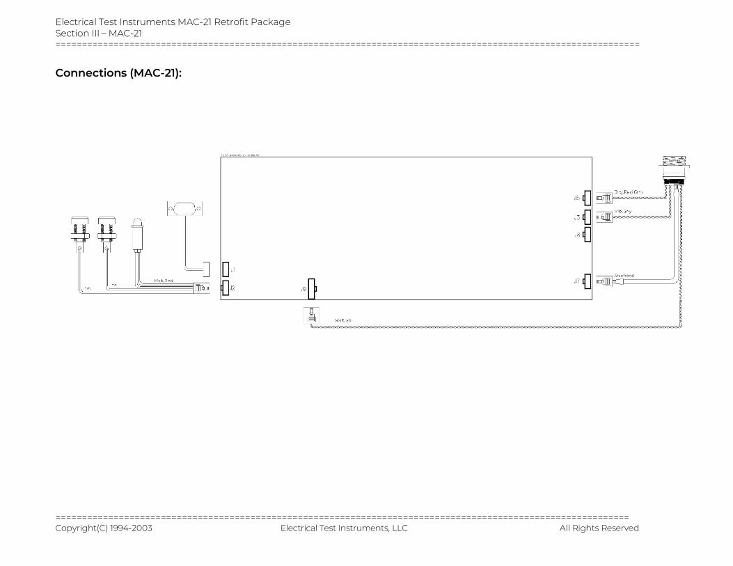
Connections (MAC-21):
Electrical Test Instruments PI-4000B Section IV - Operating Instructions ==============================================================================
============================================================================== Copyright(C) 1994-2004 Electrical Test Instruments, LLC. All Rights Reserved
SECTION IV
OPERATING INSTRUCTIONS

Electrical Test Instruments PI-4000B Section IV - Operating Instructions ==============================================================================
============================================================================== Copyright(C) 1994-2004 Electrical Test Instruments, LLC. All Rights Reserved Page IV-1
SECTION IV
OPERATING INSTRUCTIONS PRE-TEST INSTALLATION AND SET-UP 1. The following components of the test set should be available and in good
condition:
a) PI-4000B Main Unit
b) MAC-21
c) Stab set to match breaker to be tested
d) Input power plugs and cables
e) Input ground lead
f) Auxiliary ground lead
g) MAC-21 control cable
h) Contact lead set (If applicable)
i) Remote initiate cable (optional)
2. Additional requirements for testing are as follows:
a) Breakers to be tested
b) Manufacturers' curve data
c) Test log and/or report forms (See examples at end of section)
d) Basic hand tools (wrench, screwdriver, etc.)
e) Safety equipment (safety glasses, gloves, etc.)
f) Reliable and sufficient power source
g) Clean, spacious, and well-lit work area.
3. The voltage selector must be set to match input voltage.
4. Calculate KVA requirements for the source per manufacturer’s manual.
5. Locate a suitable earth ground, and connect it to the Main Control Unit with at least #6 AWG wire.
6. Connect the Ground Integrity binding post separately to earth ground.
7. Open hood cover, exposing MAC-21 and indicator control panel.
8. If possible, TURN OFF power at source.
Electrical Test Instruments PI-4000B Section IV - Operating Instructions ==============================================================================
============================================================================== Copyright(C) 1994-2004 Electrical Test Instruments, LLC. All Rights Reserved Page IV-2
9. Connect power source to input, using connectors supplied.
10. Turn on power at source, if turned off in step 8 above.
11. Input Voltage meter should indicate actual line voltage. Verify that voltage selector is set for this voltage. Input selector error LED should light if incorrect.
12. Verify that Ground Open LED is not lit. Control power cannot be turned on if ground integrity is not sensed.
13. Press Control Power switch. Green lamp should light, control panel should power up to tap 1, and MAC-21 should power up. Fans should run.
14. If Interlock lamp is not lit, press Main Power Ready switch. Main contactor should energize, and green lamp should light.
15. Connect breaker under test to appropriate output tap, using stabs or cables and series bar as required.
16. Make sure that breaker is CLOSED.
17. Follow Step-by-Step procedures below, as required, for testing.
18. When tests are completed, press INTERLOCK switch to turn Main Power OFF.
19. Press Control Power Off switch to turn Control Power OFF.
20. Turn off supply power, if possible, and disconnect input power cables.
21. Close lid on hood and secure latch (if supplied).
22. Remove ground cables from Main Control Unit to earth ground.
Electrical Test Instruments PI-4000B Section IV - Operating Instructions ==============================================================================
============================================================================== Copyright(C) 1994-2004 Electrical Test Instruments, LLC. All Rights Reserved Page IV-3
BASIC GUIDELINES AND SUGGESTIONS 1. Best timing and current accuracy will be obtained with the MAC-21 in
current latch (C.L.) mode.
2. Current Latch modes are preferred for most testing purposes. Exceptions are:
a) Non-series-connected devices such as motor overload relays or shunt-trip breakers.
b) Ratioing of current transformers.
c) Heat runs of cables, bus work, etc. (Connect contacts to thermostat).
3. If Contacts Mode is selected, use caution when connecting continuity sensing cables. Although the voltage and current are minimal, under some conditions it could cause electrical shock. ALWAYS connect one clip at a time, and NEVER rest the other hand on any current-carrying parts of the breaker while the test set is powered up.
4. Always choose an ammeter range that allows the test current to be read in the area from 20% to 80% of the maximum. This provides greatest accuracy of readings, least chance of overrange, and optimum current latch operation.
5. To obtain maximum output current from the test set, especially when using output cables, it is important to minimize both input and output impedance. This can be accomplished by using the largest cable size possible, or using multiple cables in parallel, to reduce resistance, and by keeping cables close together by tying or twisting, to reduce inductance.
6. For all breaker test sets, much better output current waveform and stability can be achieved when the controls of the test set are in their higher positions. To test smaller breakers, it is helpful to introduce additional output impedance, by using some length of adequate, but lighter gauge, wire to connect the breaker to the output connections. When using tap 1, the Vernier control should always be at least at 30% to produce desired test current.
Electrical Test Instruments PI-4000B Section IV - Operating Instructions ==============================================================================
============================================================================== Copyright(C) 1994-2004 Electrical Test Instruments, LLC. All Rights Reserved Page IV-4
SINGLE POLE MOLDED CASE CIRCUIT BREAKERS Timing Test 1. Consult breaker manufacturer's literature to determine any necessary
precautions and expected test results. A test current of three times the rating of the breaker should be used for this test.
2. Follow steps 1 through 16 in pre-test installation and setup, as required, to set up the breaker test set.
3. Setup MAC-21 for C.L. Maint (MAINTAIN on).
4. Set MAC-21 RANGE to lowest range that is greater than desired test current.
5. Set TIMEBASE to CYCLES.
6. Press PRESET key. Adjust preset time to 5.0 cycles. This value may be set higher or lower, depending on trip characteristics of breaker.
7. Press PRESET again to return to normal mode.
8. Select MEMORY mode.
9. Repeatedly jog the INITIATE button, while adjusting the OUTPUT CONTROL higher, until the desired test current is read on the ammeter. If insufficient current is obtained at maximum position of the Vernier, set the OUTPUT TAP control to the next higher tap, return the Vernier to zero, and continue.
10. Press RESET button.
11. Set TIMEBASE to SECONDS.
12. Select MAINTAIN mode.
13. Press and release INITIATE key; OUTPUT ON light should glow, timer should run, and current display should read desired output current.
14. While test is running, observe current reading. If necessary, adjust to correct value by using Vernier control, or press MAINTAIN key for current hold.
15. When breaker trips, the test set output should de-energize, timer should stop, and OUTPUT ON light should turn off.
16. Read and record trip current and trip time. Compare to manufacturer's time/current curve.
17. If test is to be repeated, make sure that breaker cools completely.
Electrical Test Instruments PI-4000B Section IV - Operating Instructions ==============================================================================
============================================================================== Copyright(C) 1994-2004 Electrical Test Instruments, LLC. All Rights Reserved Page IV-5
18. Shut down test set, disconnect breaker, and prepare for subsequent testing or relocation according to steps 18 through 22 in pre-test installation and setup outlined above.
Electrical Test Instruments PI-4000B Section IV - Operating Instructions ==============================================================================
============================================================================== Copyright(C) 1994-2004 Electrical Test Instruments, LLC. All Rights Reserved Page IV-6
Pick-Up of Instantaneous Element
1. Consult breaker manufacturer's literature to determine any necessary precautions and expected test results. Check the breaker's instantaneous setting. Pickup should occur at about that current.
2. Follow steps 1 through 16 in pre-test installation and setup, as required, to set up the breaker test set.
3. Setup MAC-21 for C.L. Maint (MAINTAIN on).
4. Set MAC-21 RANGE to lowest range that is greater than desired test current.
5. Set TIMEBASE to CYCLES.
6. Press PRESET key. Adjust preset time to 5.0 cycles. This value may be set higher or lower, depending on trip characteristics of breaker.
7. Press PRESET again to return to normal mode.
8. Select MEMORY mode.
9. Repeatedly jog the INITIATE button, while adjusting the OUTPUT CONTROL higher, until the circuit breaker trips instantaneously. This is the approximate pickup point. If insufficient current is obtained at maximum position of the Vernier, set the OUTPUT TAP control to the next higher tap, return the Vernier to zero, and continue.
10. Close breaker under test.
11. By repeating the test, determine the MINIMUM SETTING of the OUTPUT CONTROL, at which the breaker under test opens immediately, whenever the INITIATE button is depressed.
12. Read and record ammeter reading as instantaneous pick-up of the breaker.
13. Shut down test set, disconnect breaker, and prepare for subsequent testing or relocation according to steps 18 through 22 in pre-test installation and setup outlined above.

Electrical Test Instruments PI-4000B Section IV - Operating Instructions ==============================================================================
============================================================================== Copyright(C) 1994-2004 Electrical Test Instruments, LLC. All Rights Reserved Page IV-7
Instantaneous Trip Time Test
1. Perform Instantaneous Pickup Test as outlined above.
2. Adjust controls to obtain current above pickup, at approximate desired multiple of rating.
3. Close breaker under test.
4. Press the INITIATE button. Breaker should trip instantaneously.
5. Read and record timer and ammeter readings as instantaneous trip time and current.
6. Shut down test set, disconnect breaker, and prepare for subsequent testing or relocation according to steps 18 through 22 in pre-test installation and setup outlined above.
Electrical Test Instruments PI-4000B Section IV - Operating Instructions ==============================================================================
============================================================================== Copyright(C) 1994-2004 Electrical Test Instruments, LLC. All Rights Reserved Page IV-8
MULTI-POLE MOLDED CASE CIRCUIT BREAKERS
Timing Test
1. Consult breaker manufacturer's literature to determine any necessary precautions and expected test results. A test current of three times the rating of the breaker should be used for this test.
2. Follow steps 1 through 16 in pre-test installation and setup, as required, to set up the breaker test set.
3. Connect appropriate output tap to one pole of breaker under test.
4. Setup MAC-21 for C.L. Maint (MAINTAIN on).
5. Set MAC-21 RANGE to lowest range that is greater than desired test current.
6. Set TIMEBASE to CYCLES.
7. Press PRESET key. Adjust preset time to 5.0 cycles. This value may be set higher or lower, depending on trip characteristics of breaker.
8. Press PRESET again to return to normal mode.
9. Select MEMORY mode.
10. Repeatedly jog the INITIATE button, while adjusting the OUTPUT CONTROL higher, until the desired test current is read on the ammeter. If insufficient current is obtained at maximum position of the Vernier, set the OUTPUT TAP control to the next higher tap, return the Vernier to zero, and continue.
11. Press RESET button.
12. Set TIMEBASE to SECONDS.
13. Select MAINTAIN mode.
14. If desired, N.C. mode may be used; connect contacts leads to an unused pole of the breaker.
15. Press and release INITIATE key; OUTPUT ON light should glow, timer should run, and current display should read desired output current.
16. While test is running, observe current reading. If necessary, adjust to correct value by using Vernier control.
17. When breaker trips, the test set output should de-energize, timer should stop, and OUTPUT ON light should turn off.
18. Read and record trip current and trip time. Compare to manufacturer's time/current curve.
Electrical Test Instruments PI-4000B Section IV - Operating Instructions ==============================================================================
============================================================================== Copyright(C) 1994-2004 Electrical Test Instruments, LLC. All Rights Reserved Page IV-9
19. Repeat above tests for other poles of the breaker. Allow time for breaker to cool. Note: it is acceptable if all poles of the breaker trip within +/- 15% of the manufacturer's time range for the value of test current chosen. All poles of the breaker need not trip in exactly the same amount of time.
20. Shut down test set, disconnect breaker, and prepare for subsequent testing or relocation according to steps 18 through 22 in pre-test installation and setup outlined above.
Pick-Up of Instantaneous Element
1. Consult manufacturer's literature to determine any necessary precautions and expected test results. Check the breaker's instantaneous setting. Pickup should occur at about that current.
2. Follow steps 1 through 16 in pre-test installation and setup, as required, to set up the breaker test set.
3. Setup MAC-21 for C.L. MOM.
4. Set MAC-21 RANGE to lowest range that is greater than desired test current.
5. Set TIMEBASE to CYCLES.
6. Press PRESET key. Adjust preset time to 5.0 cycles. This value may be set higher or lower, depending on trip characteristics of breaker.
7. Press PRESET again to return to normal mode.
8. Select MEMORY mode.
9. Repeatedly jog the INITIATE button, while adjusting the OUTPUT CONTROL higher, until the circuit breaker trips instantaneously. This is the approximate pickup point. If insufficient current is obtained at maximum position of the Vernier, set the OUTPUT TAP control to the next higher tap, return the Vernier to zero, and continue.
10. Close breaker under test.
11. By repeating the test, determine the MINIMUM SETTING of the OUTPUT CONTROL, at which the breaker under test opens immediately, whenever the INITIATE button is depressed.
12. Read and record ammeter reading as instantaneous pick-up of the breaker.
13. Repeat the above test for the other poles of the circuit breaker.
14. Shut down test set, disconnect breaker, and prepare for subsequent testing or relocation according to steps 18 through 22 in pre-test
Electrical Test Instruments PI-4000B Section IV - Operating Instructions ==============================================================================
============================================================================== Copyright(C) 1994-2004 Electrical Test Instruments, LLC. All Rights Reserved Page IV-10
installation and setup outlined above.
Instantaneous Trip Time Test
1. Perform Instantaneous Pickup Test as outlined above.
2. Adjust controls to obtain current above pickup, at approximate desired multiple of rating.
3. Close breaker under test.
4. Press the INITIATE button. Breaker should trip instantaneously.
5. Read and record timer and ammeter readings as instantaneous trip time and current.
6. Repeat the above test for the other poles of the circuit breaker.
7. Shut down test set, disconnect breaker, and prepare for subsequent testing or relocation according to steps 18 through 22 in pre-test installation and setup outlined above.

Electrical Test Instruments PI-4000B Section IV - Operating Instructions ==============================================================================
============================================================================== Copyright(C) 1994-2004 Electrical Test Instruments, LLC. All Rights Reserved Page IV-11
LOW VOLTAGE POWER CIRCUIT BREAKERS Nearly all low voltage power circuit breakers are multi-pole devices. The trip units may be either magnetic with a dash pot or solid-state electronic devices. Test procedures would be the same for either type. However, electronic trip types may incorporate ground fault protection. If so, it is necessary to either block or by-pass ground fault protection when tests are being conducted on phase fault characteristics. This is because the tests are being conducted on one pole at a time, and the ground fault protection would consider this operation to be a ground fault. Most low voltage power circuit breakers have either Long Time Delay, and Short Time Delay, and/or instantaneous tripping characteristics. In this case, for test purposes, it is recommended that the instantaneous unit be set in its maximum calibration. This is to prevent an instantaneous trip while trying to set the current for the Short Time Delay characteristic. Electrical tests to be conducted on low voltage power circuit breakers include timing test on L.T.D.; timing test on S.T.D.; and instantaneous pick-up. It is recommended that the magnitude of test current for the L.T.D. timing test be 3 times coil rating or transformer tap. For timing test on S.T.D. the test current should be about 1.5 times the S.T.D. setting. In both cases, tripping time should be within the manufacturer's published time range. Pick-up of the instantaneous unit should be +/- 10% of the setting for the electronic device and +/- 20% of the setting for the magnetic device. Testing the instantaneous trip on very large circuit breakers set at or near maximum calibration may sometimes exceed the capacity of the test set. In most cases, the instantaneous element has several calibration marks between "LO" and "HI". In such cases, it may be necessary to perform the test at one of the lower calibration marks. Always be sure to record the "AS FOUND" settings, and return the adjustments to these settings after testing. To perform testing, adjust the screw to a lower setting that allows the test set to verify that the unit will pick up. If the instantaneous unit picks up at the proper current at a lower calibration point, it may be assumed that the unit will operate properly at higher calibration points. This has been verified by manufacturers and by means of field tests. Specific test procedures for all electrical tests are outlined on the following pages.
Electrical Test Instruments PI-4000B Section IV - Operating Instructions ==============================================================================
============================================================================== Copyright(C) 1994-2004 Electrical Test Instruments, LLC. All Rights Reserved Page IV-12
Timing Test, Long Time Delay 1. Consult breaker manufacturer's literature to determine any necessary
precautions and expected test results. A test current of three times the rating of the breaker should be used for this test.
2. Follow steps 1 through 16 in pre-test installation and setup, as required, to set up the breaker test set.
3. Connect appropriate output tap to one pole of breaker under test.
4. Setup MAC-21 for C.L. Maint (MAINTAIN on).
5. Set MAC-21 RANGE to lowest range that is greater than desired test current.
6. Set TIMEBASE to CYCLES.
7. Press PRESET key. Adjust preset time to 5.0 cycles. This value may be set higher or lower, depending on trip characteristics of breaker.
8. Press PRESET again to return to normal mode.
9. Select MEMORY mode.
10. Repeatedly jog the INITIATE button, while adjusting the OUTPUT CONTROL higher, until the desired test current is read on the ammeter. If insufficient current is obtained at maximum position of the Vernier, set the OUTPUT TAP control to the next higher tap, return the Vernier to zero, and continue.
11. Press RESET button.
12. Set TIMEBASE to SECONDS.
13. Select MAINTAIN mode.
14. If desired, N.C. mode may be used; connect contacts leads to an unused pole of the breaker.
15. Press and release INITIATE key; CLOSE or OUTPUT ON light should glow, timer should run, and current display should read desired output current.
16. While test is running, observe current reading. If necessary, adjust to correct value by using Vernier control, or press MAINTAIN key for current hold.
17. When breaker trips, the test set output should de-energize, timer should stop, and OUTPUT ON light should turn off.
18. Read and record trip current and trip time. Compare to manufacturer's time/current curve. If necessary, adjust the trip unit and repeat the test.
Electrical Test Instruments PI-4000B Section IV - Operating Instructions ==============================================================================
============================================================================== Copyright(C) 1994-2004 Electrical Test Instruments, LLC. All Rights Reserved Page IV-13
19. Repeat the above tests for the other poles of the breaker, allowing time for breaker to cool. Note: Results are acceptable if all poles of the breaker trip within the manufacturer's time range for the value of test current chosen. All poles of the breaker need not trip in exactly the same amount of time.
20. Shut down test set, disconnect breaker, and prepare for subsequent testing or relocation according to steps 18 through 22 in pre-test installation and setup outlined above.
Timing Test, Short Time Delay Note: The breaker's trip time for short time delay will always be less than 30 cycles and may be as low as 4-5 cycles. Therefore, setting test current will require some practice. However, the magnitude of the test current is not critical; for instance, if the S.T.D. is set for 1000 amperes, there will be little or no difference in timing if a test current of 1500, 2000 or 2500 amperes is used. Set up of controls is the same as for timing test L.T.D. Consult breaker manufacturer's literature to determine any necessary precautions and expected test results. 1. Follow steps 1 through 8 under Timing Test Long Time Delay.
2. Repeatedly jog the INITIATE button, while adjusting the OUTPUT CONTROL higher, until the desired test current is read on the ammeter. If insufficient current is obtained at maximum position of the Vernier, set the OUTPUT TAP control to the next higher tap, return the Vernier to zero, and continue.
3. Press RESET button.
4. Set TIMEBASE to SECONDS.
5. Select MAINTAIN mode.
6. If desired, N.C. mode may be used; connect contacts leads to an unused pole of the breaker.
7. Press and release INITIATE key; OUTPUT ON light should glow, timer should run, and current display should read desired output current.
8. Breaker should trip within 30 cycles (0.5 seconds). When breaker trips, the test set output should de-energize, timer should stop, OUTPUT ON light should turn off.
9. Read and record trip current and trip time. Compare to manufacturer's time/current curve. If necessary, adjust the trip unit and repeat the test.
Electrical Test Instruments PI-4000B Section IV - Operating Instructions ==============================================================================
============================================================================== Copyright(C) 1994-2004 Electrical Test Instruments, LLC. All Rights Reserved Page IV-14
10. Repeat the above tests for the other poles of the breaker, allowing time for breaker to cool. Note: Results are acceptable if all poles of the breaker trip within the manufacturer's time range for the value of test current chosen. All poles of the breaker need not trip in exactly the same amount of time.
11. Shut down test set, disconnect breaker, and prepare for subsequent testing or relocation according to steps 18 through 22 in pre-test installation and setup outlined above.
Pick-Up of the Instantaneous Unit 1. Consult breaker manufacturer's literature to determine any necessary
precautions and expected test results. Note: If the instantaneous setting is such that the expected test result is above that which may be easily produced by the test set, a valid test may be performed by adjusting the setting to its minimum value. At the end of the test, restore the instantaneous setting to its specified value.
2. Follow steps 1 through 16 in pre-test installation and setup, as required, to set up the breaker test set.
3. Setup MAC-21 for C.L. Maint (MAINTAIN on).
4. Set MAC-21 RANGE to lowest range that is greater than desired test current.
5. Set TIMEBASE to CYCLES.
6. Press PRESET key. Adjust preset time to 5.0 cycles. This value may be set higher or lower, depending on trip characteristics of breaker.
7. Press PRESET again to return to normal mode.
8. Select MEMORY mode.
9. Repeatedly jog the INITIATE button, while adjusting the OUTPUT CONTROL higher, until circuit breaker trips instantaneously. This is the approximate pickup point. If insufficient current is obtained at maximum position of the Vernier, set OUTPUT TAP control to next higher tap, return the Vernier to zero, and continue.
10. Close breaker under test.
11. By repeating the test, determine the MINIMUM SETTING of the OUTPUT CONTROL, at which the breaker under test opens immediately, whenever the INITIATE button is depressed.
12. Read and record ammeter reading as instantaneous pick-up of the breaker.
Electrical Test Instruments PI-4000B Section IV - Operating Instructions ==============================================================================
============================================================================== Copyright(C) 1994-2004 Electrical Test Instruments, LLC. All Rights Reserved Page IV-15
13. Repeat the above test for the other poles of the circuit breaker.
14. If trip settings were modified for test purposes, restore them to their original values.
15. Shut down test set, disconnect breaker, and prepare for subsequent testing or relocation according to steps 18 through 22 in pre-test installation and setup outlined above.
Instantaneous Trip Time Test 1. Perform Instantaneous Pickup Test as outlined above.
2. Adjust controls to obtain current above pickup, at approximate desired multiple of rating.
3. Close breaker under test.
4. Press the INITIATE button. Breaker should trip instantaneously.
5. Read and record timer and ammeter readings as instantaneous trip time and current.
6. Repeat the above test for the other poles of the circuit breaker.
7. Shut down test set, disconnect breaker, and prepare for subsequent testing or relocation according to steps 18 through 22 in pre-test installation and setup outlined above.
Electrical Test Instruments PI-4000B Section IV - Operating Instructions ==============================================================================
============================================================================== Copyright(C) 1994-2004 Electrical Test Instruments, LLC. All Rights Reserved Page IV-16
MOTOR OVERLOAD RELAYS The motor overload relay is designed to provide overload protection for a motor; therefore, it offers only one time/current characteristic, which is essentially a long-time delay. It may be multi-pole; however, most relays are single pole. In the case of a multi-pole device each pole is tested individually as in the case of a multi-pole direct acting circuit breaker. The motor overload relay contains two separate circuits. The current carrying circuit which contains the relay's operating coil or heater. The control circuit which contains a set of contacts; these contacts open when the relay "operates". It is the opening of these control circuit contacts that deenergizes the motor starter holding coils, thus allowing the starter contactors to open, shutting down the motor. Timing Tests 1. Consult the relay manufacturer's literature to determine any necessary
precautions and the expected timing test results. The test current should be 3 to 4 times the rating of the relay operating coil or heater.
2. Follow steps 1 through 16 in pre-test installation and setup, as required, to set up the breaker test set.
3. Setup MAC-21 for C.L. Maint (MAINTAIN on).
4. Set MAC-21 RANGE to lowest range that is greater than desired test current.
5. Set TIMEBASE to CYCLES.
6. Press PRESET key. Adjust preset time to 5.0 cycles. This value may be set higher or lower, depending on trip characteristics of breaker.
7. Press PRESET again to return to normal mode.
8. Select MEMORY mode.
9. Connect the relay operating coil or heater circuit terminals to the breaker test set common terminal and the proper output tap terminal.
10. Connect the relay control circuit contacts to the CONTACTS terminals, and determine that they are closed by observing the CONTINUITY lamp.
11. Repeatedly jog the INITIATE button, while adjusting the OUTPUT CONTROL higher, until the desired test current is read on the ammeter. If insufficient current is obtained at maximum position of the Vernier, set the
Electrical Test Instruments PI-4000B Section IV - Operating Instructions ==============================================================================
============================================================================== Copyright(C) 1994-2004 Electrical Test Instruments, LLC. All Rights Reserved Page IV-17
OUTPUT TAP control to the next higher tap, return the Vernier to zero, and continue.
12. Press RESET button.
13. Set MAC-21 to N.C. mode. Set MAINTAIN on.
14. Press and release INITIATE button; OUTPUT ON light should glow, timer should operate, and current should indicate on display.
15. When the relay control circuit contacts open, the test set output should deenergize and the timer should stop.
16. Read and record the test value of current and the time of the test. Compare the results to the manufacturer's specifications. If possible, adjust the relay. Usually, if the relay time of operation is incorrect, it is necessary to replace the relay heater with one of the recommended sizes for the motor being protected. If a check test is desired, the relay must be allowed to cool for a period of time (approximately 15 to 30 minutes).
17. For a multi-pole relay, repeat the above tests for the other relay poles.
18. Shut down test set, disconnect breaker, and prepare for subsequent testing or relocation according to steps 18 through 22 in pre-test installation and setup outlined above.
Electrical Test Instruments PI-4000B Section IV - Operating Instructions ==============================================================================
============================================================================== Copyright(C) 1994-2004 Electrical Test Instruments, LLC. All Rights Reserved Page IV-18
RATIOING CURRENT TRANSFORMERS To conduct a ratio test on a current transformer, a good multi-range bench ammeter is required in addition to the breaker test set. The breaker test set supplies primary current to the transformer and the bench ammeter is used to read the transformer secondary current. It is suggested that a graph of the test results be plotted. Primary current should be the abscissa and corresponding secondary current the ordinate of the graph. WARNING: It is extremely important that the secondary circuit of the current transformer never be broken or opened while the primary circuit is energized. Should the secondary circuit of an energized current transformer be opened, the collapsing magnetic field generates an extremely high voltage across the open ends of the circuit until the resultant arc is extinguished. Under these conditions, personal injury and/or damage to the current transformer under test are probable.
1. Follow steps 1 through 16 in pre-test installation and setup, as required, to set up the breaker test set.
2. Connect the current transformer primary terminals to the breaker test set common terminal and the proper output tap terminal.
3. Connect the current transformer secondary terminals to the bench ammeter.
4. Set the MAC-21 to N.O. mode. Set MAINTAIN on.
5. Press and release INITIATE button; CLOSE or OUTPUT ON light should glow, timer should operate, and current should indicate on display.
6. Adjust OUTPUT CONTROL higher until the desired current transformer primary current is read on the MAC-21 ammeter. Adjust OUTPUT TAP switch, if necessary, to obtain required current.
7. Read and record the readings on both the breaker test set (MAC-21) and the bench ammeter.
8. Repeat steps 6 and 7 until the desired number of test points have been obtained. Note: It is suggested that test points be obtained in multiples of the current transformer rating. For instance, for a 200/5 current transformer, test points would be obtained at primary currents of 200, 400, 600, 800 amperes, etc.
9. Shut down test set, disconnect CT, and prepare for subsequent testing or relocation according to steps 18 through 22 in pre-test installation and setup outlined above.
Electrical Test Instruments PI-4000B Section V - Service Information and Documentation
==============================================================================
============================================================================== Copyright(C) 1994-2004 Electrical Test Instruments, LLC. All Rights Reserved
SECTION V
SERVICE INFORMATION AND DOCUMENTATION

Electrical Test Instruments PI-4000B Section V - Service Information and Documentation ==============================================================================
============================================================================= Copyright(C) 1994-2004 Electrical Test Instruments, LLC. All Rights Reserved Page V-1
SECTION V
SERVICE INFORMATION AND DOCUMENTATION MAINTENANCE AND CALIBRATION OF THE PI-4000B The PI-4000B requires only minimal maintenance. Mechanical components such as casters and hinges may need periodic lubrication. External surfaces should be kept clean, and screws on access panels should be checked for tightness. The output stab adapter plates must be kept clean and smooth, and studs should be maintained in good condition. Poor output connections are the main cause of overheating and poor performance. Occasionally, or more often if used in dusty environments, it is important to inspect and clean interior components. Disconnect from all sources of power, and remove all access covers. Carefully blow out any dust, and inspect all connections for tightness and any sign of deterioration due to corrosion or overheating. The fans should be cleaned with a damp rag, and checked for signs of bearing wear by spinning. Vernier brushes should be inspected for signs of wear or overheating, and cleaned or replaced as required. Calibration of the PI-4000B requires accurate current measurement in both series and parallel connection. Adjustment may be accomplished by means of the potentiometers accessible through the output stab plate. The outer pot is for parallel connection, and the inner pot is for series. MAINTENANCE AND CALIBRATION OF THE MAC-21 The MAC-21 is manufactured using solid state components that should not require extensive maintenance. However, the accuracy of the MAC-21 is critical to the testing of circuit breakers, and is dependent upon the output of an air-core current sensing coil, which could change due to movement caused by shock or vibration encountered in transporting the test set. Other factors which may affect calibration are contact resistance in the control cable, unusual magnetic fields, insulation leakage, and aging of electronic components in the MAC-21. Therefore, proper operation and calibration should be checked at regular intervals, and adjusted if proper equipment is available. The manufacturer’s recommended calibration interval is (1) one year.
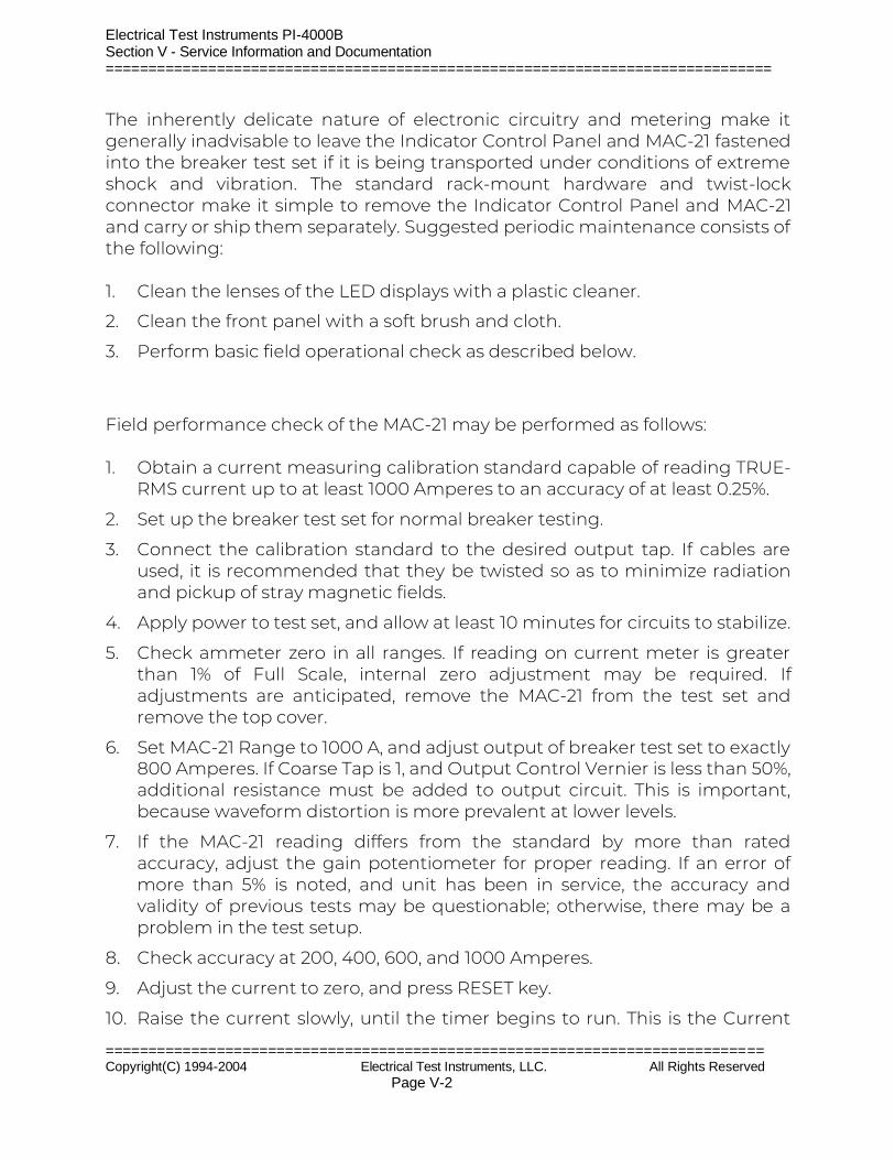
Electrical Test Instruments PI-4000B Section V - Service Information and Documentation ==============================================================================
============================================================================= Copyright(C) 1994-2004 Electrical Test Instruments, LLC. All Rights Reserved Page V-2
The inherently delicate nature of electronic circuitry and metering make it generally inadvisable to leave the Indicator Control Panel and MAC-21 fastened into the breaker test set if it is being transported under conditions of extreme shock and vibration. The standard rack-mount hardware and twist-lock connector make it simple to remove the Indicator Control Panel and MAC-21 and carry or ship them separately. Suggested periodic maintenance consists of the following: 1. Clean the lenses of the LED displays with a plastic cleaner.
2. Clean the front panel with a soft brush and cloth.
3. Perform basic field operational check as described below.
Field performance check of the MAC-21 may be performed as follows: 1. Obtain a current measuring calibration standard capable of reading TRUE-
RMS current up to at least 1000 Amperes to an accuracy of at least 0.25%.
2. Set up the breaker test set for normal breaker testing.
3. Connect the calibration standard to the desired output tap. If cables are used, it is recommended that they be twisted so as to minimize radiation and pickup of stray magnetic fields.
4. Apply power to test set, and allow at least 10 minutes for circuits to stabilize.
5. Check ammeter zero in all ranges. If reading on current meter is greater than 1% of Full Scale, internal zero adjustment may be required. If adjustments are anticipated, remove the MAC-21 from the test set and remove the top cover.
6. Set MAC-21 Range to 1000 A, and adjust output of breaker test set to exactly 800 Amperes. If Coarse Tap is 1, and Output Control Vernier is less than 50%, additional resistance must be added to output circuit. This is important, because waveform distortion is more prevalent at lower levels.
7. If the MAC-21 reading differs from the standard by more than rated accuracy, adjust the gain potentiometer for proper reading. If an error of more than 5% is noted, and unit has been in service, the accuracy and validity of previous tests may be questionable; otherwise, there may be a problem in the test setup.
8. Check accuracy at 200, 400, 600, and 1000 Amperes.
9. Adjust the current to zero, and press RESET key.
10. Raise the current slowly, until the timer begins to run. This is the Current
Electrical Test Instruments PI-4000B Section V - Service Information and Documentation ==============================================================================
============================================================================= Copyright(C) 1994-2004 Electrical Test Instruments, LLC. All Rights Reserved Page V-3
Latch Threshold, which should be about 5% of full-scale range.
11. Set the current at 50% of full scale (500 A), and stop the current.
12. Set the MAC-21 to MEMORY mode, and press the RESET Switch.
13. Initiate a fast-momentary pulse of no more than 6 cycles (0.1 Sec) duration. The meter should read the same value, within 2%, that was set in step 11 above.
14. Check pulse reading operation in this manner for currents of 200, 400, 600, and 1000 Amperes, and varying duration.
15. Set Timer Time base to SECONDS. Press Master Reset Switch. Set N.O. mode. Using a timing standard, initiate for exactly ninety (90) seconds. Timer should read 90.00 Seconds, +/- 0.01 Seconds. (Note: actual reading may vary because of inability to control and measure pulse length.)
16. If everything checks out, the MAC-21 can be assumed to be in calibration, and no other adjustments are required.
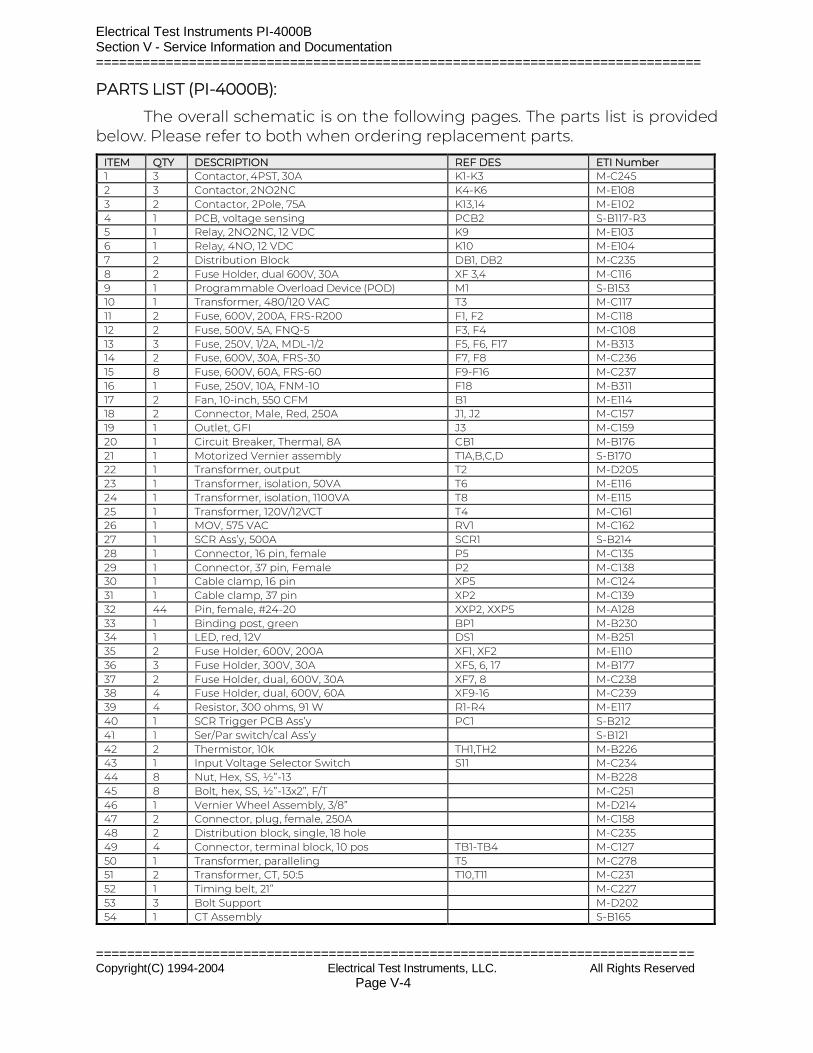
Electrical Test Instruments PI-4000B Section V - Service Information and Documentation ==============================================================================
============================================================================= Copyright(C) 1994-2004 Electrical Test Instruments, LLC. All Rights Reserved Page V-4
PARTS LIST (PI-4000B):
The overall schematic is on the following pages. The parts list is provided below. Please refer to both when ordering replacement parts.
ITEM QTY DESCRIPTION REF DES ETI Number 1 3 Contactor, 4PST, 30A K1-K3 M-C245 2 3 Contactor, 2NO2NC K4-K6 M-E108 3 2 Contactor, 2Pole, 75A K13,14 M-E102 4 1 PCB, voltage sensing PCB2 S-B117-R3 5 1 Relay, 2NO2NC, 12 VDC K9 M-E103 6 1 Relay, 4NO, 12 VDC K10 M-E104 7 2 Distribution Block DB1, DB2 M-C235 8 2 Fuse Holder, dual 600V, 30A XF 3,4 M-C116 9 1 Programmable Overload Device (POD) M1 S-B153 10 1 Transformer, 480/120 VAC T3 M-C117 11 2 Fuse, 600V, 200A, FRS-R200 F1, F2 M-C118 12 2 Fuse, 500V, 5A, FNQ-5 F3, F4 M-C108 13 3 Fuse, 250V, 1/2A, MDL-1/2 F5, F6, F17 M-B313 14 2 Fuse, 600V, 30A, FRS-30 F7, F8 M-C236 15 8 Fuse, 600V, 60A, FRS-60 F9-F16 M-C237 16 1 Fuse, 250V, 10A, FNM-10 F18 M-B311 17 2 Fan, 10-inch, 550 CFM B1 M-E114 18 2 Connector, Male, Red, 250A J1, J2 M-C157 19 1 Outlet, GFI J3 M-C159 20 1 Circuit Breaker, Thermal, 8A CB1 M-B176 21 1 Motorized Vernier assembly T1A,B,C,D S-B170 22 1 Transformer, output T2 M-D205 23 1 Transformer, isolation, 50VA T6 M-E116 24 1 Transformer, isolation, 1100VA T8 M-E115 25 1 Transformer, 120V/12VCT T4 M-C161 26 1 MOV, 575 VAC RV1 M-C162 27 1 SCR Ass’y, 500A SCR1 S-B214 28 1 Connector, 16 pin, female P5 M-C135 29 1 Connector, 37 pin, Female P2 M-C138 30 1 Cable clamp, 16 pin XP5 M-C124 31 1 Cable clamp, 37 pin XP2 M-C139 32 44 Pin, female, #24-20 XXP2, XXP5 M-A128 33 1 Binding post, green BP1 M-B230 34 1 LED, red, 12V DS1 M-B251 35 2 Fuse Holder, 600V, 200A XF1, XF2 M-E110 36 3 Fuse Holder, 300V, 30A XF5, 6, 17 M-B177 37 2 Fuse Holder, dual, 600V, 30A XF7, 8 M-C238 38 4 Fuse Holder, dual, 600V, 60A XF9-16 M-C239 39 4 Resistor, 300 ohms, 91 W R1-R4 M-E117 40 1 SCR Trigger PCB Ass’y PC1 S-B212 41 1 Ser/Par switch/cal Ass’y S-B121 42 2 Thermistor, 10k TH1,TH2 M-B226 43 1 Input Voltage Selector Switch S11 M-C234 44 8 Nut, Hex, SS, ½”-13 M-B228 45 8 Bolt, hex, SS, ½”-13x2”, F/T M-C251 46 1 Vernier Wheel Assembly, 3/8” M-D214 47 2 Connector, plug, female, 250A M-C158 48 2 Distribution block, single, 18 hole M-C235 49 4 Connector, terminal block, 10 pos TB1-TB4 M-C127 50 1 Transformer, paralleling T5 M-C278 51 2 Transformer, CT, 50:5 T10,T11 M-C231 52 1 Timing belt, 21” M-C227 53 3 Bolt Support M-D202 54 1 CT Assembly S-B165
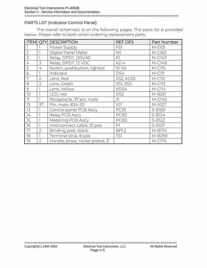
Electrical Test Instruments PI-4000B Section V - Service Information and Documentation ==============================================================================
============================================================================= Copyright(C) 1994-2004 Electrical Test Instruments, LLC. All Rights Reserved Page V-5
PARTS LIST (Indicator Control Panel):
The overall schematic is on the following pages. The parts list is provided below. Please refer to both when ordering replacement parts.
ITEM QTY DESCRIPTION REF DES Part Number 1 1 Power Supply PS1 M-E101 2 1 Digital Panel Meter M1 M-C163 3 1 Relay, DPDT, 120VAC K1 M-C147 4 3 Relay, DPDT, 12 VDC K2-4 M-C149 5 4 Switch, pushbutton, lighted S1-S4 M-C110 6 1 Indicator DS4 M-C111 7 2 Lens, Red XS2, XDS2 M-C112 8 2 Lens, Green XS1, XS3 M-C113 9 1 Lens, Yellow XDS4 M-C114 10 1 LED, red DS5 M-B251 11 1 Receptacle, 37 pin, male J1 M-C140 12 37 Pin, male, #24-20 XJ1 M-A127 13 1 Control panel PCB Ass’y PCB1 S-B169 14 1 Relay PCB Ass’y PCB2 S-B124 15 1 Metering PCB Ass’y PCB3 S-B122 16 1 Interconnect cable, 10 pos P1 S-A107 17 2 Binding post, black BP1,2 M-B174 18 1 Terminal strip, 8 pos TS1 M-B259 19 2 Handle, brass, nickel plated, 3” M-C174
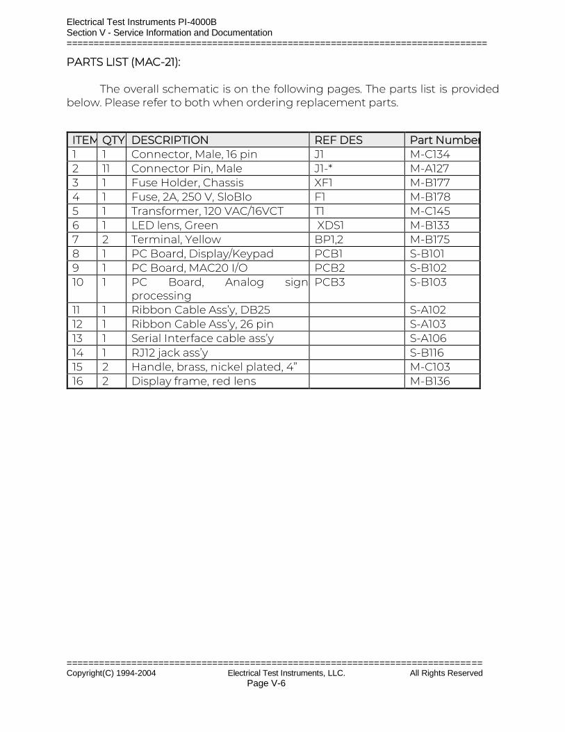
Electrical Test Instruments PI-4000B Section V - Service Information and Documentation ==============================================================================
============================================================================= Copyright(C) 1994-2004 Electrical Test Instruments, LLC. All Rights Reserved Page V-6
PARTS LIST (MAC-21): The overall schematic is on the following pages. The parts list is provided below. Please refer to both when ordering replacement parts.
ITEM QTY DESCRIPTION REF DES Part Number 1 1 Connector, Male, 16 pin J1 M-C134 2 11 Connector Pin, Male J1-* M-A127 3 1 Fuse Holder, Chassis XF1 M-B177 4 1 Fuse, 2A, 250 V, SloBlo F1 M-B178 5 1 Transformer, 120 VAC/16VCT T1 M-C145 6 1 LED lens, Green XDS1 M-B133 7 2 Terminal, Yellow BP1,2 M-B175 8 1 PC Board, Display/Keypad PCB1 S-B101 9 1 PC Board, MAC20 I/O PCB2 S-B102 10 1 PC Board, Analog signal
processing PCB3 S-B103
11 1 Ribbon Cable Ass’y, DB25 S-A102 12 1 Ribbon Cable Ass’y, 26 pin S-A103 13 1 Serial Interface cable ass’y S-A106 14 1 RJ12 jack ass’y S-B116 15 2 Handle, brass, nickel plated, 4” M-C103 16 2 Display frame, red lens M-B136
Electrical Test Instruments PI-4000B Section V - Service Information and Documentation
=========================================================================================================
============================================================================================================= Copyright(C) 1994-2004 Electrical Test Instruments, LLC. All Rights Reserved Page V-7
OVERALL SCHEMATIC (PI-4000B)
OVERALL SCHEMATIC (Indicator Control Panel)
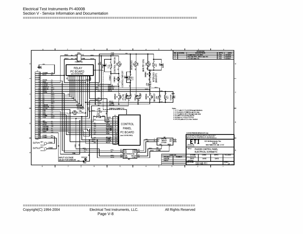
Electrical Test Instruments PI-4000B Section V - Service Information and Documentation ==============================================================================
============================================================================= Copyright(C) 1994-2004 Electrical Test Instruments, LLC. All Rights Reserved Page V-8
Electrical Test Instruments PI-4000B Section IV - Service Information and Documentation
==============================================================================
============================================================================== Copyright(C) 1994-2003 Electrical Test Instruments, LLC. All Rights Reserved
Electrical Test Instruments Retrofit Package Section V - Service Information and Documentation
==============================================================================
WARRANTY Electrical Test Instruments, LLC, will correct any defect in workmanship or material for two years after date of purchase of any Electrical Test Instruments product. Such corrective measures will be limited to repairing or replacing the unit, at Electrical Test Instruments' option. This limited warranty shall not apply to equipment which has been subjected to negligence, accident or damage by operation, maintenance or storage, or to non-normal use or service. This limited warranty does not cover reimbursements for transportation, removal, installation, repair or replacement, except as may otherwise be specifically agreed to in writing by Electrical Test Instruments. The foregoing is in lieu of all other warranties expressed or implied, and all other obligations or liabilities whether arising under contract, negligence or otherwise, on the part of Electrical Test Instruments. In no event shall Electrical Test Instruments be liable for consequential or special damages, including but not limited to loss of use, loss of income, loss of profit or cost of replacement.