Embed Size (px)
Citation preview

Back to Contents Slide 1
PRIMER 16.0

Slide 2Back to Contents
PRIMER 16.0 - Contents
• Keyword Input and Output
• Improvements for Large Models
• Morphing
• Meshing Improvements
• Shell Split
• Geometry Mesh
• Swages Updates
• ICFD Setup
• Displaying Shell Normals
• ISO Geometric Analyses
• *CONSTRAINED
• Connections
• Multi Stage Positioning
• Seatsquash
• Undo for Renumbering
• Adding/Replacing and Include File
• New Orient Translate Option
• New Options for Orient Dialogue Command
• Rigidwall Visualisation
• Rigidify Panel Options
• Display and Cut-Section Options
• FMH Markup Tool
• Pedestrian Markup Tool
• Images
• JavaScript API
• Model Check
• Element Quality Checks
• LS-DYNA Output Files
• PTF/d3plot Write
• Preferences
• Licensing 16.0

Back to Contents Slide 3
Keyword Input and Output

Slide 4Back to Contents
Input and Output Improvements
• Keyword input and output significantly faster for large models due to increased parallelisation
of i/o and other improvements. Data are i/o times in seconds.
File sizes:
• Raw ascii 5.0 GBytes
• Zipped ascii 1.3 GBytes
• Raw binary 1.6 Gbytes
• Zipped binary 0.8 Gbytes

Slide 5Back to Contents
Input and Output Improvements
• Zipped (ascii and binary) i/o on a slow or congested network will be significantly
better than raw i/o because smaller file sizes mean less network traffic.
Local disk i/o shows proportionally similar speed improvements.
• Can now read encrypted .zip format files.
Will detect encryption and prompt for a password
(Note: PRIMER does not *write* encrypted files.)
• Binary Keyword files now get the extension “.kby” to distinguish them from “.key”.
• When a directory contains multiple versions of an include file, for example:
child.key (Original file)
child.kby (File modified in PRIMER and written out in binary format)
PRIMER searches all variants and lists them, but reads the newest by default.

Back to Contents Slide 6
Other Improvements for Large Models

Slide 7Back to Contents
Other Improvements for Large Models
These improvements apply to models of all sizes, but will become more noticeable for
models with > 10m elements and nodes:
• Response to “change of graphics” is faster:
• Application of blanking and unblanking at least 2x faster.
• Selection of parts, elements and nodes by area at least 2x faster.
• Cut-section display improved.
• Speed of dragging a cut-section through a model dramatically (> 5x) faster.
• As with the improvements to Model Check and Keyword input most of the increase in
speed comes from parallelisation. This trend will continue, and the larger the model
the more it will benefit from a greater number of cores on the machine.

Back to Contents Slide 8
Morphing

Slide 9Back to Contents
High Order Morph Boxes
Morph boxes can now have more than 2 by 2 by 2 morph
points. These high order morph boxes give you more control
over mesh smoothness while morphing.
Basic order
box with 2 by
2 by 2 points
High order
box with 3 by
2 by 2 points

Slide 10Back to Contents
A Box With Different Morph Point Visibility
Corner points only Corner and edge
points visible
Corner, edge and
face points visibleAll morph points
visible

Slide 11Back to Contents
Morph Point Interpolation
Original position No interpolation Full interpolation
Morph point movements can be interpolated. Without interpolation only
the explicitly selected morph points move, whereas with interpolation
others move as well by a fraction of the vector. This is illustrated in the
pictures where only one edge point is explicitly selected. The option
“Hidden points only” only interpolates those whose visibility is turned off.
Slide 12Back to Contents
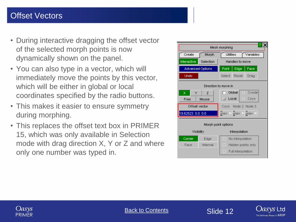
Offset Vectors
• During interactive dragging the offset vector
of the selected morph points is now
dynamically shown on the panel.
• You can also type in a vector, which will
immediately move the points by this vector,
which will be either in global or local
coordinates specified by the radio buttons.
• This makes it easier to ensure symmetry
during morphing.
• This replaces the offset text box in PRIMER
15, which was only available in Selection
mode with drag direction X, Y or Z and where
only one number was typed in.

Slide 13Back to Contents
Deleting Morph Boxes
• The Reset tab in PRIMER 15 has
now been replaced with a Utilities
tab, which also allows deletion of
morph boxes.
Slide 14Back to Contents
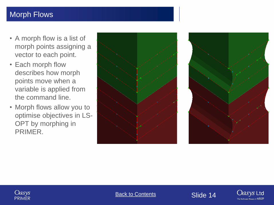
Morph Flows
• A morph flow is a list of
morph points assigning a
vector to each point.
• Each morph flow
describes how morph
points move when a
variable is applied from
the command line.
• Morph flows allow you to
optimise objectives in LS-
OPT by morphing in
PRIMER.

Slide 15Back to Contents
Morphing Tutorials
• Tutorials are available on
Help -> Tutorials.
• The Morph Boxes with High
Order tutorial explains in more
detail how smoothness can be
controlled and what options
are available.
• Details of the setup and the
use for LS-OPT can be found
in the Morphing Optimisation
tutorial.

Back to Contents Slide 16
Meshing Improvements

Slide 17Back to Contents
Meshing Improvements
Corners can be preserved
during remeshing around
spotwelds:
• Corners formed by an angle
on one shell only are always
preserved
• Corners formed by an angle at
the junction of two (or more)
shells are preserved if that
angle is greater than a user
specified value. This value can
be saved as preference.
Corners preserved at
(default) 10° setting
Corners not
preserved at 20°
setting

Back to Contents Slide 18
Shell Split Using 3x3 Split

Slide 19Back to Contents
Shell Split Using 3x3 Split
• A “3x3” option has been added to Shell split. Shell can be split using ‘Single’ option as well as
‘Multiple’ option.
Mesh Tools->Split->Shell panel
Predefined split
pattern popup
Input
Output

Back to Contents Slide 20
Geometry Mesh

Slide 21Back to Contents
Geometry Mesh
• PRIMER v16.0 has ability to mesh the selected surface into a single meshed part. For example the image
below shows 12 surfaces that we want to mesh. Each of the 12 surfaces will be meshed together rather
than creating nodes along the shared surface edges.
• Select the surface(s) that you want to mesh in the object menu and press Apply in the object menu.
PRIMER will then show the surfaces that will be meshed together with Grey line boundaries and fixed
points with Grey circles.

Slide 22Back to Contents
Geometry Mesh
• Once the surfaces have been selected and a part ID is given the Apply button will become active.
• If you press it then PRIMER will show a preview of the mesh that will be generated.
Preview of mesh
Meshed surface

Back to Contents Slide 23
Swages Updates

Slide 24Back to Contents
Mesh Tools -> Swages
• Mesh Tools -> “Swages” is used to create swages/beads in shell meshes.

Slide 25Back to Contents
Mesh Tools -> Swages (cont.)
• To define the swage path, previously only points on
shells could be used. Now the user can also use nodal
points to define a path.
• A new ‘Outline’ button just shows the outline of the
proposed swage sketch.
• The TOP surface of the swage can be created in a
circular shape with a new input parameter : R1. This
parameter can take values up to half the size of the TOP
surface width, or half the size of the Swage Height,
whichever is lower.

Back to Contents Slide 26
ICFD Setup

Slide 27Back to Contents
ICFD Model Setup Tool
A new tool has been created to generate an ICFD model from shell parts.
It includes an option to create far field fluid boundaries around a central
specified part.

Slide 28Back to Contents
ICFD Model Setup Tool
Option to automatically create far field boundaries around
central part.

Slide 29Back to Contents
ICFD Model Setup Tool
Boundary Inputs
Keywords automatically
created

Slide 30Back to Contents
ICFD Model Setup Tool

Back to Contents Slide 31
Displaying Shell Normals

Slide 32Back to Contents
Display Shell Normals as Arrows
• A “Vector” sub option has been added in View->Contour plots->Shell Normals to display
the direction of shell normals as arrows (rather than shell contouring).
• The length of the arrows can be changed in View->contour plots->Settings panel.
• The shell normal arrows can also be accessed from the Shell Elements panel: Elements->
Shell-> Normals/Align
• The “Draw Normals” toggle button displays the shell normal direction as Arrows.
• The shell normals can be drawn for the “Selected” shells (via ‘Select Shells’) or for all the “All”
shells in the model.
• The length of the shell normal arrows can be changed in the same panel.
View->Contour plots popup Shell Normals settings panel Elements-> Shell-> Normals/Align panel

Slide 33Back to Contents
Display Shell Normals as Arrows
Shell Normals->Contour sub option Shell Normals->Vector sub option

Slide 34Back to Contents
Hex Assembly Column in Connection Table
• A column “Hex Assembly” has been added to the connection table.
• The column shows the labels of Hex assemblies
(*DEFINE_HEX_SPOTWELD_ASSEMBLY) of solid elements associated
with connection entities in the model.
Connection table along with Hex Assembly column

Back to Contents Slide 35
Iso Geometric Analyses

Slide 36Back to Contents
Iso Geometric Analyses
Iso Geometric Analyses can be run in LS-DYNA using the keywords
*ELEMENT_SHELL_NURBS_PATCH and *DEFINE_NURBS_CURVE to define the surfaces.
In v16 PRIMER can now display those surfaces.
Slide 37Back to Contents
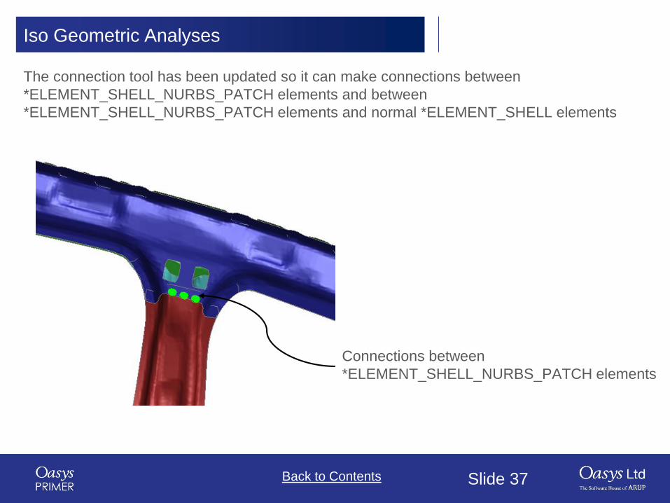
Iso Geometric Analyses
The connection tool has been updated so it can make connections between
*ELEMENT_SHELL_NURBS_PATCH elements and between
*ELEMENT_SHELL_NURBS_PATCH elements and normal *ELEMENT_SHELL elements
Connections between
*ELEMENT_SHELL_NURBS_PATCH elements

Back to Contents Slide 38
*CONSTRAINED

Slide 39Back to Contents
*CONSTRAINED_INTERPOLATION_SPOTWELD C_SPR C_SPR2
These are now drawn using projection to the specified sheets
Default is red head on master part and green
tail. On Display > colour this may be changed
to colour by node set

Back to Contents Slide 40
Connections
Slide 41Back to Contents
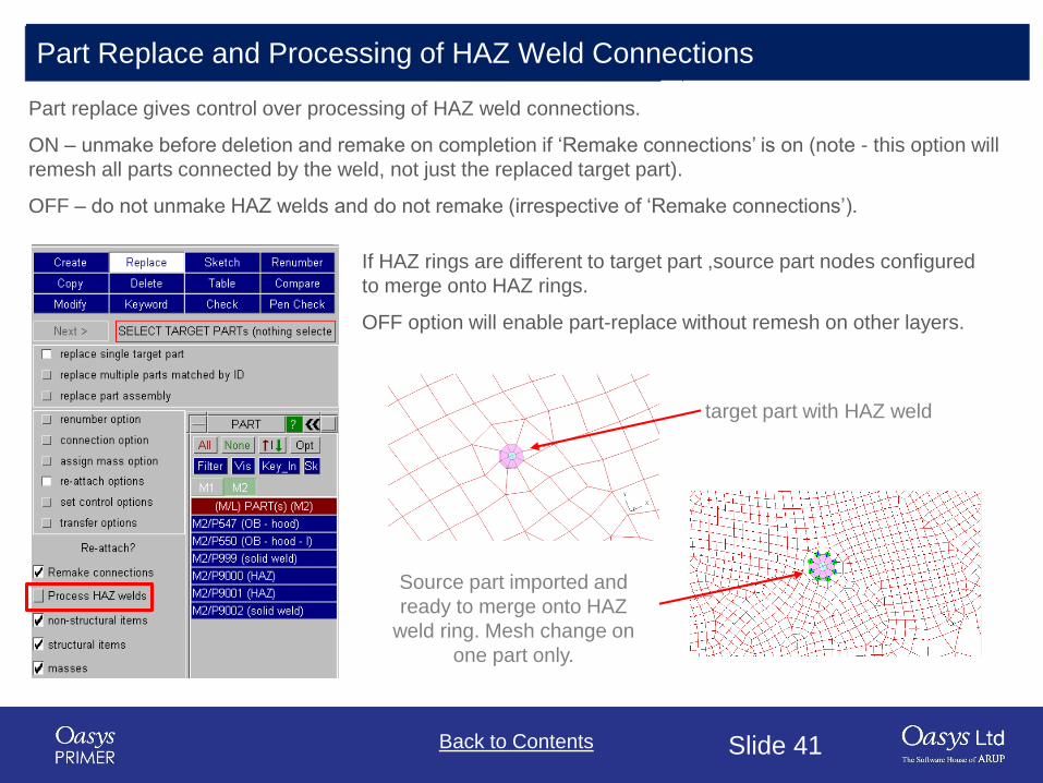
Part Replace and Processing of HAZ Weld Connections
Part replace gives control over processing of HAZ weld connections.
ON – unmake before deletion and remake on completion if ‘Remake connections’ is on (note - this option will
remesh all parts connected by the weld, not just the replaced target part).
OFF – do not unmake HAZ welds and do not remake (irrespective of ‘Remake connections’).
If HAZ rings are different to target part ,source part nodes configured
to merge onto HAZ rings.
OFF option will enable part-replace without remesh on other layers.
target part with HAZ weld
Source part imported and
ready to merge onto HAZ
weld ring. Mesh change on
one part only.

Slide 42Back to Contents
Welding to SOLIDS, TSHELLS & SHELL_NURBS_PATCH
PRIMER spot-welder will now form segments on external faces of shell/solid/tshell parts and on
shell_nurbs_patch enabling welds (or adhesive) to be made to them.
Selection of all elements for weld creation in
spotweld mode now considers shells, solids
and shell_nurb_patch under “All”.

Slide 43Back to Contents
NRB Bolt Connections Across Includes use SET_COLLECT
If NRB bolt connection spans include files, PRIMER will use
SET_COLLECT to avoid SET_LIST with latent nodes which can
get lost e.g. accidental cleanup on stand alone include.Include 1 read stand alone has nset
Include 2 read stand alone has nrb
Master file shows NRB from
complete node set

Back to Contents Slide 44
Multi Stage Positioning
Slide 45Back to Contents
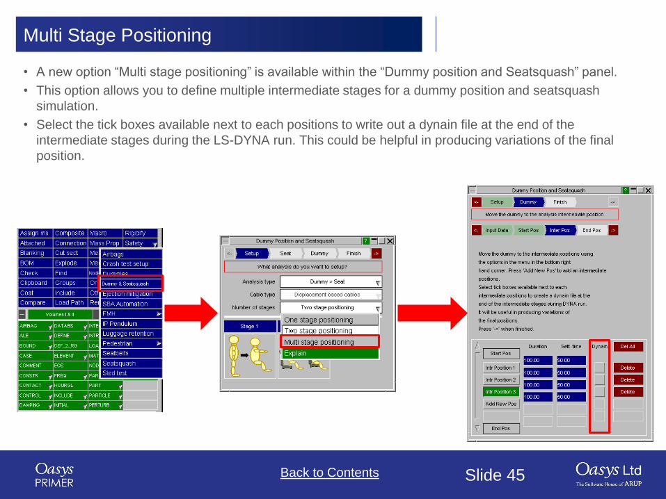
Multi Stage Positioning
• A new option “Multi stage positioning” is available within the “Dummy position and Seatsquash” panel.
• This option allows you to define multiple intermediate stages for a dummy position and seatsquash
simulation.
• Select the tick boxes available next to each positions to write out a dynain file at the end of the
intermediate stages during the LS-DYNA run. This could be helpful in producing variations of the final
position.

Slide 46Back to Contents
Multi Stage Positioning
• Example of multi-stage positioning – all in one analysis:
Stage 1 – Occupant starts
above seat
Stage 2 – Occupant is moved
into seat (seat-squash)
Stage3 – Arms are moved to
either side of the steering
wheel

Slide 47Back to Contents
Multi Stage Positioning
• Example of multi-stage positioning – all in one analysis:
Stage 4 – Hands moved onto
steering wheel
Stage 5 – Feet moved onto
pedals – dynain file produced
Stage 6 – Hands moved to
different position on steering
wheel – dynain file produced

Back to Contents Slide 48
Seatsquash

Slide 49Back to Contents
Alternative Method for Outputting dynain File
An LS-DYNA seatsquash analysis set up in
PRIMER will, by default, output a dynain using the
*INTERFACE_SPRINGBACK keyword.
In LS-DYNA R9, any parts that use *MAT_FABRIC
using this method are not output to the dynain file,
so an alternative method of outputting the dynain
file has been added.
This uses STAGED_CONSTRUCTION cards and
can be selected interactively on the seatsquash
menu and set with the preference.
primer*squash_use_define_construction: TRUE

Back to Contents Slide 50
Undo for Renumbering
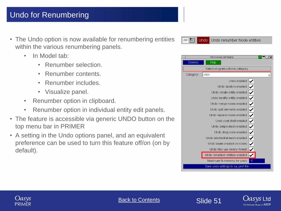
Slide 51Back to Contents
Undo for Renumbering
• The Undo option is now available for renumbering entities
within the various renumbering panels.
• In Model tab:
• Renumber selection.
• Renumber contents.
• Renumber includes.
• Visualize panel.
• Renumber option in clipboard.
• Renumber option in individual entity edit panels.
• The feature is accessible via generic UNDO button on the
top menu bar in PRIMER
• A setting in the Undo options panel, and an equivalent
preference can be used to turn this feature off/on (on by
default).

Back to Contents Slide 52
Adding/Replacing an INCLUDE file

Slide 53Back to Contents
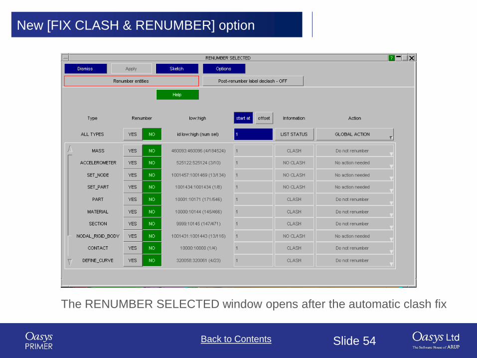
New [FIX CLASH & RENUMBER] Option
• When adding or replaying an include file, if label clashes are detected, users now
have the option to manually renumber the corrected include file.
New option added
Slide 54Back to Contents
New [FIX CLASH & RENUMBER] option
The RENUMBER SELECTED window opens after the automatic clash fix
Back to Contents Slide 55
New Orient Translate Option

Slide 56Back to Contents
New [VECTOR] Option
• The orient tool now has a [VECTOR]
option under the Translate tab that
works similar to the [N1->N2] option.

Back to Contents Slide 57
New Options for Orient Dialogue
Command

Slide 58Back to Contents
New option for Orient command
• New options for orient contact are available as dialogue input (text input) command.
• “ADD_GAP” adjusts the back off distance of the entities from the point of contact.
• “THICKNESS” (Contact Thk) over-rides the actual contact thickness if non-zero.

Back to Contents Slide 59
Rigidwall Visualisation

Slide 60Back to Contents
Added Visualisation of Normal Vector

Back to Contents Slide 61
Rigidify Panel Options

Slide 62Back to Contents
Rigidify Panel Options
• Extra options (CMO, CON1, CON2) are available on the
rigidify panel.(Tools->Rigidify).
• These allow you to set the rigid material (MAT_20)
properties CMO, CON1 and CON2 directly from the panel
while rigidifying parts of your model.
• These fields are available for both ‘Rigidify part of model’
and ‘Bolt (make rigid patch)’ options.
Tools->Rigidify (Part Panel)

Back to Contents Slide 63
Display and Cut-Section Options
Slide 64Back to Contents
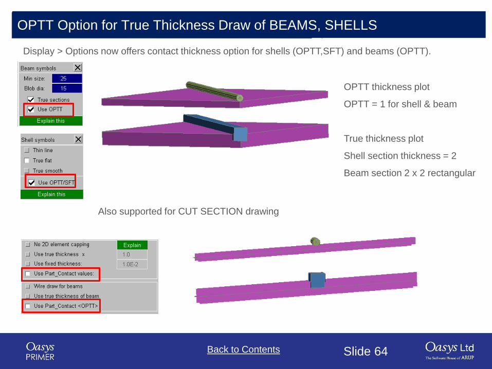
OPTT Option for True Thickness Draw of BEAMS, SHELLS
Display > Options now offers contact thickness option for shells (OPTT,SFT) and beams (OPTT).
OPTT thickness plot
OPTT = 1 for shell & beam
True thickness plot
Shell section thickness = 2
Beam section 2 x 2 rectangular
Also supported for CUT SECTION drawing

Back to Contents Slide 65
FMH Markup Tool

Slide 66Back to Contents
FMH: Settings Options
• Settings options on the 1st panel has
been moved to the bottom of the
window
• Settings options added to the final
panel

Slide 67Back to Contents
FMH: New Prompts
• New prompts have been added to give
users more information on what to
select, and also provide checking
feedback.

Slide 68Back to Contents
SR2 Calculation
• There are now two
ways to calculate target
point SR2.
1. Default: With
respect to APR.
2. With respect to BPR
(or RPR if there is
no B-pillar).

Slide 69Back to Contents
SR2 with respect to APR

Slide 70Back to Contents
SR2 with respect to BPR
Slide 71Back to Contents
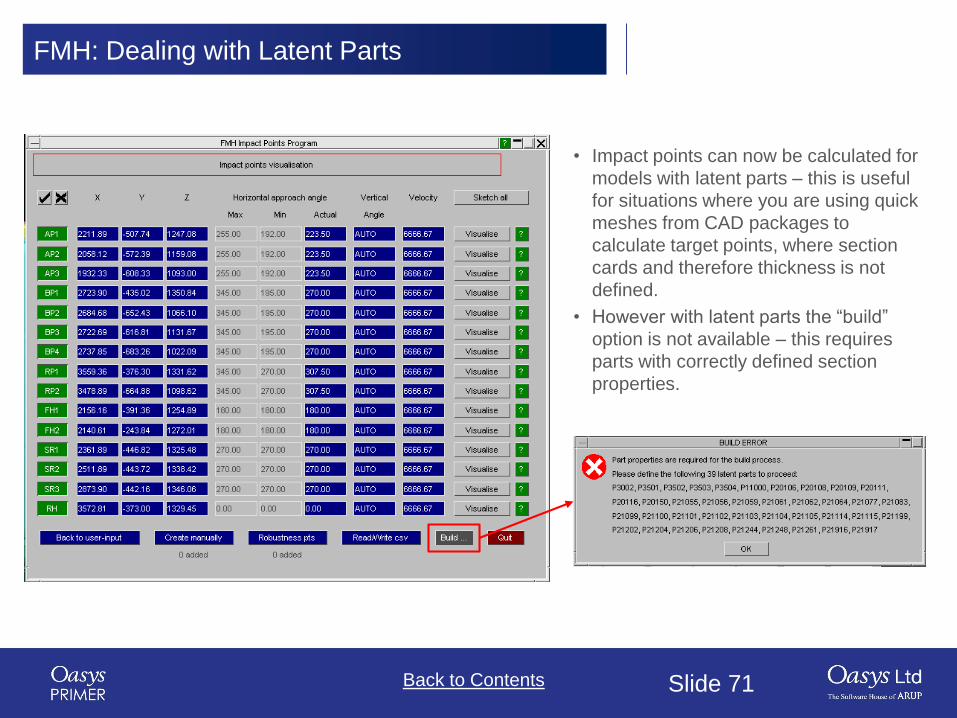
FMH: Dealing with Latent Parts
• Impact points can now be calculated for
models with latent parts – this is useful
for situations where you are using quick
meshes from CAD packages to
calculate target points, where section
cards and therefore thickness is not
defined.
• However with latent parts the “build”
option is not available – this requires
parts with correctly defined section
properties.

Back to Contents Slide 72
Pedestrian Markup Tool

Slide 73Back to Contents
Pedestrian Markup Tool
The model output by the pedestrian markup tool containing the “sticks” and mark-up information now also
contains the outline of the semi-circular template used to join the rear reference line with the side reference line.
Back to Contents Slide 74
Images
Slide 75Back to Contents
Images
PRIMER 16 introduces the following changes to the handling of output image filenames:
• If an explicit filename (optionally, with path) is typed in or selected for one image type, say JPEG, that
new filename and path will then become a seed for every image type. Changing to a different image
type, say PNG, will not require users to browse to the user-defined path again. Instead the new seed
name will be used for the PNG file with the appropriate extension (.png) and a unique increment
<nnn> added if needed.
• Extensions that are an obvious mismatch will be auto-corrected and a warning issued. For example, if
a user attempts to write out a BMP with the filename myfile.gif, the filename will be changed to
myfile.bmp automatically. The filename myfile.image will, however, not be auto-corrected.
• If a user-chosen filename exists, clicking the ‘NEW_FILE’ option will not take the user back to the
current working directory as was done in the past. Instead, a unique 3 digit increment <nnn> will be
appended to the same name to generate a new filename.
• A sub-folder (one level only) is now also automatically created as a part of image creation, if needed.
• All of the above now also applies to postscript files (PS and PDF), although the handling of images
and postscript files is kept disparate. So, choosing a new image name will not alter the default
filename for movie or postscript files. Choosing a new postscript filename will, however, update the
default filename for pdfs.

Back to Contents Slide 76
JavaScript API

Slide 77Back to Contents
JavaScript API
• Various JavaScript API enhancements include:
• The object returned from the Dummy GetPoint() method now includes a ‘hpt’ property that is
true if the point has been automatically generated by PRIMER at the H-point.
• There are now new classes MorphPoint and MorphBox for the existing morphing keywords as
well as MorphFlow for the new post-*END keyword *MORPH_FLOW.
• A new class function FlagVisible() is added for Part class. The API can flag all the visible or
unblanked parts in a model.
• The part class function CentreOfGravity has been re-written to allow user control of the mass
calculation. The following options are supported, for example:
var cofg = p.CentreOfGravity({slaveparts:true, skipslave:true, transfermass:true,
lumpedmass:true, nrbmass:false, timestep_mass:false,
plot:true});
• Updates to keyword classes for R11.0 (see manual).

Back to Contents Slide 78
Model Check

Slide 79Back to Contents
Model Check Improvements
• Up to 20% faster for a typical model, very model content dependent.
• Substantially (2x or better) faster for models containing many solids and thick shells when
these are used in tied contacts.
• Substantially (2x or better) faster for models containing many adhesive and spotweld
connections. (The speed of use of the connection table also benefits from this.)
Much of the speed up comes from further parallelisation of bottle-necks, and the improvement will depend
heavily on model size, content and organisation. Also on the number of available cores.
Generally the larger the model the more it will benefit from parallelisation, as splitting tasks up over cores has
a fixed overhead, but larger models require more useful work. In a large model the ratio of
(useful work / overhead)
improves, because the length of a “run” of useful work per core gets longer. Large models will also benefit
more from a greater number of cores for the same reason. PRIMER currently limits this sort of parallelism to
min(#cores, 16) threads by default, but this limit can be changed.
Hyper-threading (2 logical cores per physical core) helps a little, perhaps 10% in a large model.

Back to Contents Slide 80
Element Quality Checks

Slide 81Back to Contents
Element Quality Checks
Two new element quality checks have been
added:
• Max taper (SHELL elements only)
𝑡𝑎𝑝𝑒𝑟 = 1 −2𝐴𝑖𝐴𝑞𝑢𝑎𝑑 𝑚𝑎𝑥
• Min tetra collapse (SOLID elements only)
𝑡𝑒𝑡 𝑐𝑜𝑙𝑙𝑎𝑝𝑠𝑒 =ℎ𝑖
1.24 𝐴𝑖 𝑚𝑖𝑛
Checking can be toggled on/off as well as the
failure criteria and weighting factors specified via
the ‘CHECK OPTIONS’ panel.
(weighting factors are used in
giving quality checks precedence
in ‘Quality Imperfection’ and
‘Failed Criteria’ CT/SI plots)
Tetra Collapse
Taper
Taper & Tet Collapse values can also be obtained
via the JavaScript API:
s.Taper() - (where s is a SHELL object)
s.TetCollapse() - (where s is a SOLID object)

Slide 82Back to Contents
Element Quality Checks
These element checks can be displayed as contour plots:

Slide 83Back to Contents
Element Quality Checks
These checks can also feed into Quality Imperfection and Failed Criteria contour plots:
Slide 84Back to Contents
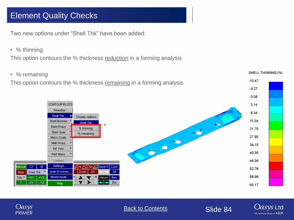
Element Quality Checks
Two new options under “Shell Thk” have been added:
• % thinning
This option contours the % thickness reduction in a forming analysis
• % remaining
This option contours the % thickness remaining in a forming analysis

Slide 85Back to Contents
Element Quality Checks
New contour option: LOAD SHELL DIRECTION.
This adds the ability to contour LOAD SHELL initial direction:
• Blue Loading in away direction.
• Magenta Loading in towards direction.
• Yellow Loading in both directions.
• Grey No loading.

Slide 86Back to Contents
Element Quality Checks
A JavaScript function has been added to display a contour plot of any of the Quality Checks:
View.SetContourType
The function takes 1 or 2 arguments, depending on what you want to contour:
• Type.
• Subtype.
Examples:
• View.SetContourType(View.LOADSHELLDIRECTION);
• View.SetContourType(View.ELEMPROPS, View.FORMULATION);

Back to Contents Slide 87
LS-DYNA Output Files

Slide 88Back to Contents
LS-DYNA Output Files
ToolsCheckDYNA Output.
More search criteria:
• mes*
• *.mes*
• *.d3hsp
• User specified ‘Additional search’
• Compressed file search
Additional search:
• Turn on or off via check box
• Can use wildcards:
‘?’ – one character
‘*’ – any number of characters
• Can save as preferences:
‘additional_dyna_output’ – search string
‘additional_dyna_output_search’ – search turned on/off
(TRUE/FALSE)

Slide 89Back to Contents
LS-DYNA Output Files
ToolsCheckDYNA Output
More search criteria:
• mes*
• *.mes*
• *.d3hsp
• User specified ‘Additional search’
• Compressed file search
Compressed search:
• Turn on or off via check box.
• Searches for files ending in “.gz” or “.zip”.
• When such files are selected, clicking ‘Apply’ will open
them and present their data just like any other non-
compressed file.

Slide 90Back to Contents
LS-DYNA Output Files
You can now view 100
smallest timesteps data:
• Viewing of timestep messages
can be toggled on/off with the
‘smallest timesteps’ button.
• Error mode will show
messages in order of
ascending timestep value.
• Item mode will show
messages in order of
ascending entity label.
• As with existing warnings, if
the entity being referred to
exists, further operations can
be performed (Only, Sketch,
Edit etc.).

Back to Contents Slide 91
PTF / d3plot Write

Slide 92Back to Contents
PTF / d3plot Write
Prior to v16, if a model contained
*INITIAL_STRESS_(T)SHELL cards with multiple on plan
points (NPLANES > 1), the PTF / d3plot writer would only
write data for the first integration point on each layer.
This restriction has been removed in v16 and it now writes the
data for each on plan point.

Slide 93Back to Contents
PTF / d3plot Write
A new option has been added to the PTF / d3plot writer to add
space for on plan integration point results.
If the file doesn't contain any *INITIAL_STRESS_(T)SHELL
cards the file will only contain one data slot for stress data per
(T)SHELL. Users may want to create a JavaScript user defined
UBIN component in D3PLOT to add values to the model and
this limitation means they can only write it at one layer and one
on plan point.
Selecting the option to add space for on plan integration point
results will make PRIMER write a file with data slots available
for multiple on plan points (the number of layers will still be
limited to 1).
NOTE: The ELFORM field on the *SECTION card needs to be
set to a formulation that supports multiple on plan integration
points otherwise D3PLOT will still think it only has space for
one on plan point.

Back to Contents Slide 94
Preferences
Slide 95Back to Contents
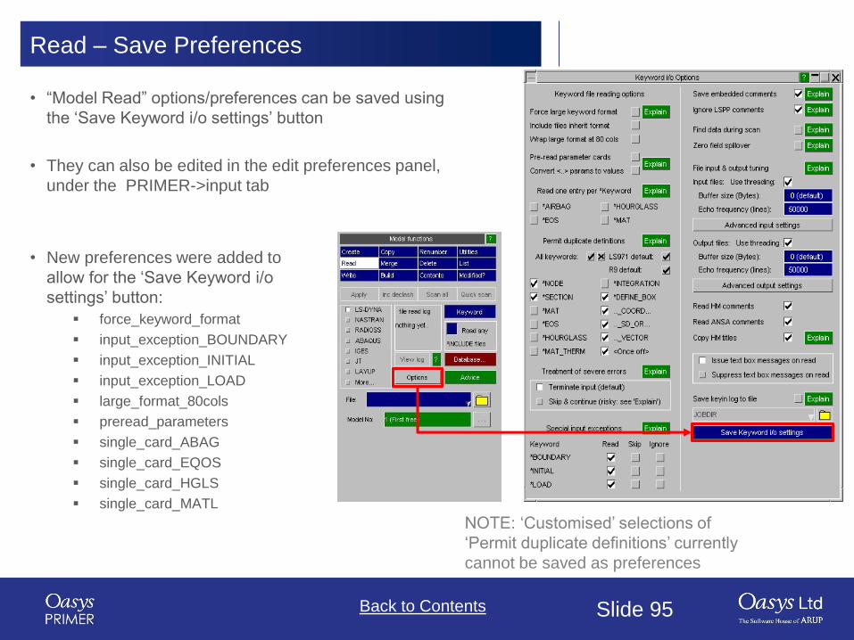
Read – Save Preferences
• New preferences were added to
allow for the ‘Save Keyword i/o
settings’ button:
▪ force_keyword_format
▪ input_exception_BOUNDARY
▪ input_exception_INITIAL
▪ input_exception_LOAD
▪ large_format_80cols
▪ preread_parameters
▪ single_card_ABAG
▪ single_card_EQOS
▪ single_card_HGLS
▪ single_card_MATL
NOTE: ‘Customised’ selections of
‘Permit duplicate definitions’ currently
cannot be saved as preferences
• “Model Read” options/preferences can be saved using
the ‘Save Keyword i/o settings’ button
• They can also be edited in the edit preferences panel,
under the PRIMER->input tab

Slide 96Back to Contents
Text Edit of Preference File
• In addition to the preference editing tool, PRIMER now supports text edit of a
preference file.
• User gets choice to edit Home or Install oa_pref (if permissions allow).
How to load modified preferences to current session
• If preferences are created/modified but not deleted REREAD PRIMER PREFS
will load the preference files without loss of any current settings. This process
will effectively ignore deleted prefs – those settings will be unchanged.
• If preferences have been deleted RESET PRIMER PREFS will reset all
possible preference settings to default and then load the preference files.
• Both options will read Admin, Install, Home and cwd preference files in that
order.

Slide 97Back to Contents
New Preference for Composite ztf Output
• When writing a ztf file for a
model containing composite
data, without any PRIMER ply
information, The below
message appears, giving the
user the option to create
PRIMER ply information to aid
post-processing of composite
information.
• New preference
‘ztf_output_composite_action’
can be used to preselect the
option on this dialogue box (set
to ‘Yes_Del’, ‘Yes’, or ‘No’).

Slide 98Back to Contents Slide 98Back to Contents Slide 98Back to Contents Slide 98Back to ContentsBack to Contents Slide 98
Licensing 16.0
Slide 99Back to Contents Slide 99Back to Contents Slide 99Back to Contents Slide 99Back to ContentsBack to Contents Slide 99
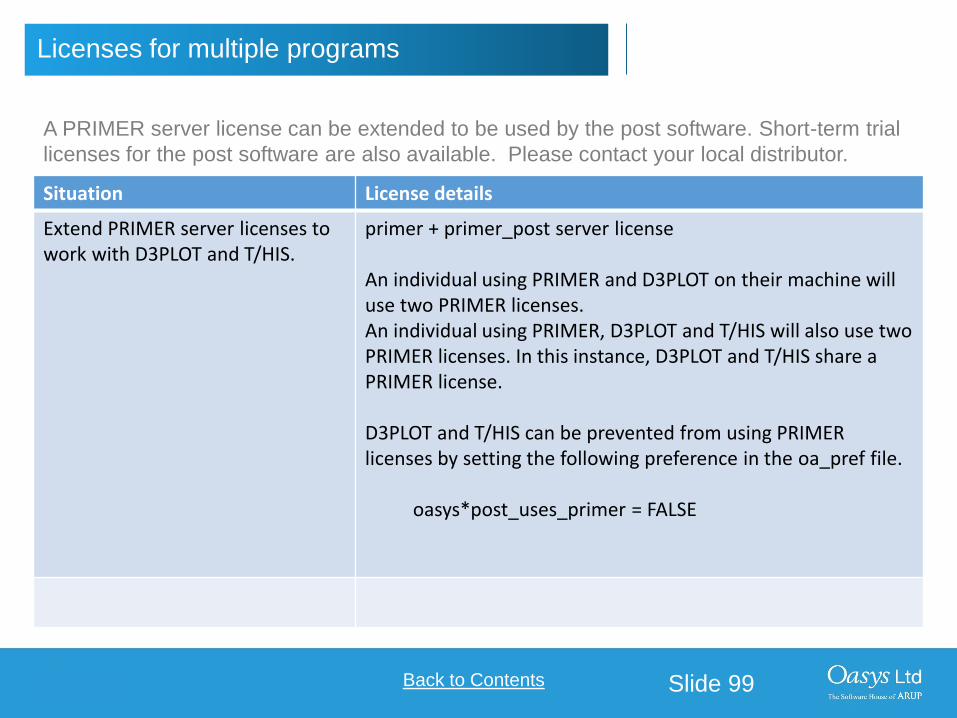
Licenses for multiple programs
Situation License details
Extend PRIMER server licenses to work with D3PLOT and T/HIS.
primer + primer_post server license
An individual using PRIMER and D3PLOT on their machine will use two PRIMER licenses.An individual using PRIMER, D3PLOT and T/HIS will also use two PRIMER licenses. In this instance, D3PLOT and T/HIS share a PRIMER license.
D3PLOT and T/HIS can be prevented from using PRIMER licenses by setting the following preference in the oa_pref file.
oasys*post_uses_primer = FALSE
A PRIMER server license can be extended to be used by the post software. Short-term trial
licenses for the post software are also available. Please contact your local distributor.

Slide 100Back to Contents Slide 100Back to Contents Slide 100Back to Contents Slide 100Back to ContentsBack to Contents Slide 100
Licenses for multiple programs (trial access)
Situation License
PRIMER with trial access to D3PLOT and T/HIS for server licenses.
primer + post_trial server license
An individual can use PRIMER, D3PLOT and T/HIS simultaneously on their machine. Doing so will use one ‘primer’ server license and one ‘post_trial’ server license.
Once the trial license expires, only PRIMER can be accessed.
PRIMER with trial access to D3PLOT and T/HIS for node-locked licenses.
primer + post_trial node-locked license
You can use PRIMER, D3PLOT and T/HIS simultaneously on your machine.
Once the trial license expires, only PRIMER can be accessed.
D3PLOT with trial access to T/HIS. This will enable you to use the T/HIS link.
d3plot + post_trial
You can use D3PLOT and T/HIS simultaneously on your machine.
Once the trial license expires, only D3PLOT can be accessed.

Slide 101Back to Contents Slide 101Back to Contents Slide 101Back to Contents Slide 101Back to ContentsBack to Contents Slide 101
Licenses for single or multiple programs
You can buy server or node locked licenses which allow access to all programs in the
Oasys Suite.
It is also possible to buy server or node locked licenses for individual programs.
Program License required
PRIMER primer
D3PLOT d3plot
T/HIS this
D3PLOT and T/HIS link d3plot + this
REPORTER reporter*
All programs in the Oasys Suite primer, d3plot, this + reporter
*REPORTER is also able to run without the reporter license. In this situation the software
checks for any available Oasys license and then releases it again.

Slide 102Back to Contents Slide 102Back to Contents Slide 102Back to Contents Slide 102Back to ContentsBack to Contents Slide 102
Restricted-use licenses for all programs
We provide restricted-use licenses free of charge through our website www.arup.com/dyna
for certain domain names, for example for students at UK Universities.
These licenses can also be sold commercially by a local distributor.
Similar licenses are available restricted to a different number of nodes or curves.
Program License
All programs in the Oasys Suite, restricted to models with less than 10,000 nodes (PRIMER and D3PLOT) and 12 curves (T/HIS).
primer, d3plot and this licenses restricted

Slide 103Back to Contents Slide 103Back to Contents Slide 103Back to Contents Slide 103Back to ContentsBack to Contents Slide 103
REPORTER and SHELL licensing
REPORTER
If you have licenses for any of our programs, you are licensed to use REPORTER to
interact with that program.
For example, if you have a “primer” license, you can use PRIMER, or use REPORTER
to create reports with PRIMER objects in them.
SHELL
The Oasys SHELL can be used without a license.

Slide 104Back to Contents Slide 104Back to Contents Slide 104Back to Contents Slide 104Back to ContentsBack to Contents Slide 104
FAQs

Slide 105Back to Contents Slide 105Back to Contents Slide 105Back to Contents Slide 105Back to ContentsBack to Contents Slide 105
Using the extended PRIMER license
1. License check-out priority - When customer has both the extended PRIMER license
(primer + primer_post) and D3PLOT license (d3plot), which license will be checked
out first when running D3PLOT?
D3PLOT will always look for a D3PLOT license first. If no D3PLOT licenses are available, it will then try and use a PRIMER license. If D3PLOT uses a PRIMER license then by default a window is displayed warning the user that they are using a PRIMER license.
2. Can a user on one machine have a unlimited number of PRIMER sessions with one
primer license (as was previously the case)?
This hasn’t changed if they are running versions 16 or 15. In versions 16 or 15 if a user runs multiple copies of PRIMER on the same machine then they all share a single license.
If a user runs version 14 and either version 16 or 15 at the same time then they will count as 2 separate licenses.

Slide 106Back to Contents Slide 106Back to Contents Slide 106Back to Contents Slide 106Back to ContentsBack to Contents Slide 106
Using the extended PRIMER license (CON’T)
3. Can you let me know how to prevent D3PLOT and T/HIS using a PRIMER license?
To disable license sharing the following preference can be set:
d3plot*post_uses_primer: FALSE
(disables D3PLOT from using a PRIMER license)
this*post_uses_primer: FALSE
(disables T/HIS from using a PRIMER license)
oasys*post_uses_primer: FALSE
(disables D3PLOT and T/HIS from using a PRIMER license)
4. How many extended PRIMER licenses does an individual use?
D3PLOT (or T/HIS) using a PRIMER license is counted separately to a user running PRIMER so an individual on one terminal, running the following combinations of program uses these licenses:
1) 1 x PRIMER only : 1 primer license2) 2 x PRIMER : 1 primer license3) PRIMER + D3PLOT : 2 primer licenses4) 2 x PRIMER + 2 x D3PLOT : 2 primer licenses5) PRIMER + T/HIS : 2 primer licenses6) PRIMER + T/HIS + D3PLOT : 2 primer licenses (D3PLOT and T/HIS share)

Slide 107Back to Contents Slide 107Back to Contents Slide 107Back to Contents Slide 107Back to ContentsBack to Contents Slide 107
Changing from FLEXlm to LMX licensing
We are planning to discontinue the use of FLEXlm licensing in our software from version 17.0 onwards.
We will instead use LMX licensing. Support for LMX licenses is included in our Oasys suite versions 15.x
and 16.x software. The table shows which Oasys suite versions work with each license type.
LMX licenses will be available later in the year for testing purposes.
Oasys Suite version FLEXlm licensing LMX licensing
14.x and earlier
15.x and 16.x
17.x onwards

Slide 108Back to Contents Slide 108Back to Contents Slide 108Back to Contents Slide 108Back to ContentsBack to Contents Slide 108
Contact Information
UK Contact:
The Arup Campus
Blythe Valley Park
Solihull
United Kingdom
B90 8AE
T: +44 121 213 3399
For more information please contact the following:
www.arup.com/dyna
China Contact:
Arup China
39/F-41/F Huaihai Plaza 1045 Huaihai Road (M) Xuhui District, Shanghai China
200031
T: +86 21 3118 8875 [email protected]
India Contact:
Arup India
Ananth Info Park, HiTec City
Madhapur Phase-II
Hyderabad
India
500081, Telangana
T: +91 40 44369797 / 98
USA West Contact:
Arup Americas
c/o 560 Mission Street Suite 700
San Francisco
United States
CA 94105
T: +1 415 940 0959
or your local Oasys distributor