Embed Size (px)
Citation preview
ARL-TR-7479 ● SEP 2015
US Army Research Laboratory
Primer Output and Initial Projectile Motion for 5.56- and 7.62-mm Ammunition
by John J Ritter and Richard A Beyer Approved for public release; distribution is unlimited.

NOTICES
Disclaimers The findings in this report are not to be construed as an official Department of the Army position unless so designated by other authorized documents. Citation of manufacturer’s or trade names does not constitute an official endorsement or approval of the use thereof. Destroy this report when it is no longer needed. Do not return it to the originator.

ARL-TR-7479 ● SEP 2015
US Army Research Laboratory
Primer Output and Initial Projectile Motion for 5.56- and 7.62-mm Ammunition
by John J Ritter and Richard A Beyer Weapons and Materials Research Directorate, ARL Approved for public release; distribution is unlimited.
FOR OFFICIAL USE ONLY (delete if not FOUO)
ii
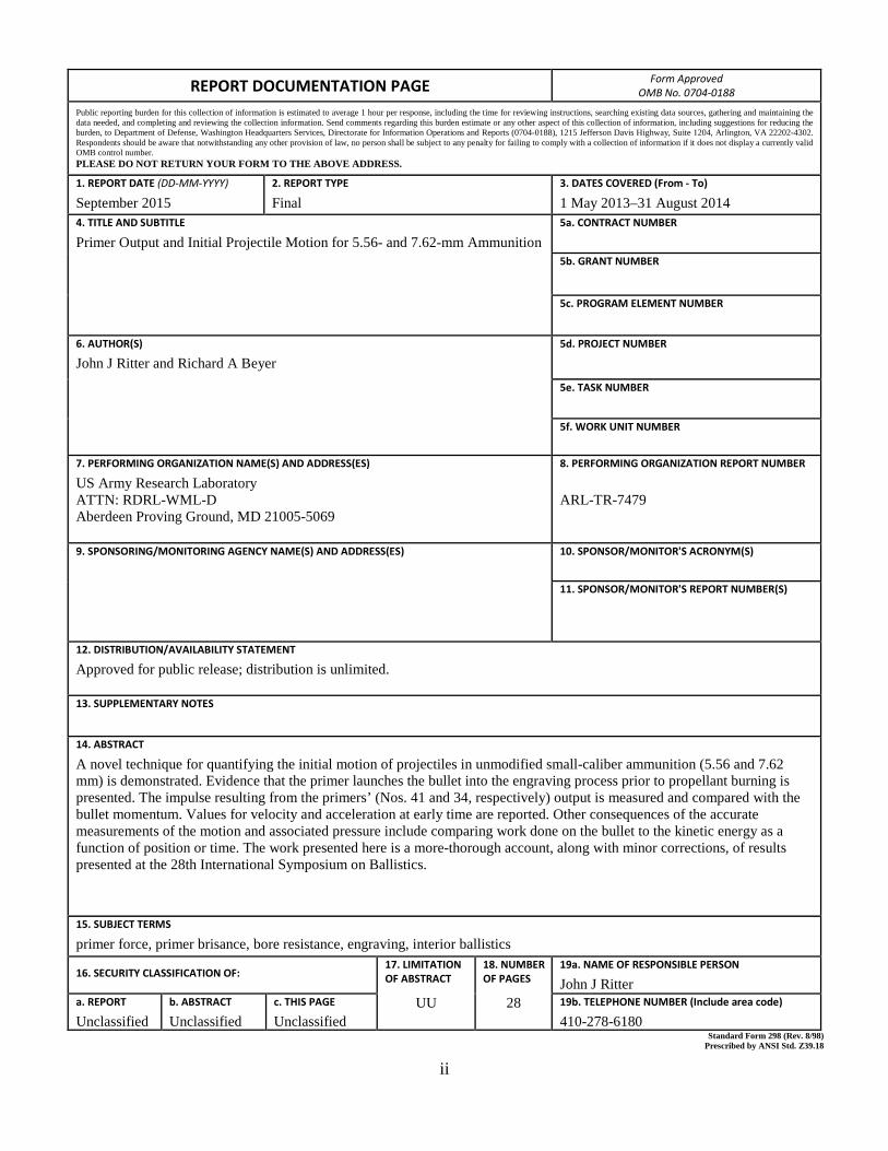
REPORT DOCUMENTATION PAGE Form Approved OMB No. 0704-0188
Public reporting burden for this collection of information is estimated to average 1 hour per response, including the time for reviewing instructions, searching existing data sources, gathering and maintaining the data needed, and completing and reviewing the collection information. Send comments regarding this burden estimate or any other aspect of this collection of information, including suggestions for reducing the burden, to Department of Defense, Washington Headquarters Services, Directorate for Information Operations and Reports (0704-0188), 1215 Jefferson Davis Highway, Suite 1204, Arlington, VA 22202-4302. Respondents should be aware that notwithstanding any other provision of law, no person shall be subject to any penalty for failing to comply with a collection of information if it does not display a currently valid OMB control number. PLEASE DO NOT RETURN YOUR FORM TO THE ABOVE ADDRESS.
1. REPORT DATE (DD-MM-YYYY)
September 2015 2. REPORT TYPE
Final 3. DATES COVERED (From - To)
1 May 2013–31 August 2014 4. TITLE AND SUBTITLE
Primer Output and Initial Projectile Motion for 5.56- and 7.62-mm Ammunition 5a. CONTRACT NUMBER
5b. GRANT NUMBER
5c. PROGRAM ELEMENT NUMBER
6. AUTHOR(S)
John J Ritter and Richard A Beyer 5d. PROJECT NUMBER
5e. TASK NUMBER
5f. WORK UNIT NUMBER
7. PERFORMING ORGANIZATION NAME(S) AND ADDRESS(ES)
US Army Research Laboratory ATTN: RDRL-WML-D Aberdeen Proving Ground, MD 21005-5069
8. PERFORMING ORGANIZATION REPORT NUMBER
ARL-TR-7479
9. SPONSORING/MONITORING AGENCY NAME(S) AND ADDRESS(ES)
10. SPONSOR/MONITOR'S ACRONYM(S)
11. SPONSOR/MONITOR'S REPORT NUMBER(S)
12. DISTRIBUTION/AVAILABILITY STATEMENT
Approved for public release; distribution is unlimited.
13. SUPPLEMENTARY NOTES
14. ABSTRACT
A novel technique for quantifying the initial motion of projectiles in unmodified small-caliber ammunition (5.56 and 7.62 mm) is demonstrated. Evidence that the primer launches the bullet into the engraving process prior to propellant burning is presented. The impulse resulting from the primers’ (Nos. 41 and 34, respectively) output is measured and compared with the bullet momentum. Values for velocity and acceleration at early time are reported. Other consequences of the accurate measurements of the motion and associated pressure include comparing work done on the bullet to the kinetic energy as a function of position or time. The work presented here is a more-thorough account, along with minor corrections, of results presented at the 28th International Symposium on Ballistics.
15. SUBJECT TERMS
primer force, primer brisance, bore resistance, engraving, interior ballistics
16. SECURITY CLASSIFICATION OF: 17. LIMITATION OF ABSTRACT
UU
18. NUMBER OF PAGES
28
19a. NAME OF RESPONSIBLE PERSON
John J Ritter a. REPORT
Unclassified b. ABSTRACT
Unclassified c. THIS PAGE
Unclassified 19b. TELEPHONE NUMBER (Include area code)
410-278-6180 Standard Form 298 (Rev. 8/98) Prescribed by ANSI Std. Z39.18

iii
Contents
List of Figures iv
Acknowledgments v
1. Introduction 1
2. Approach 2
3. Results 4
3.1 Bullet-Rifling Interface 4
3.2 Motion Analysis 4
3.3 Observations of Bullet Motion between Rifled and Smoothbore Barrels 8
3.4 Primer Impulse and Bullet Momentum Measurements 9
3.5 Further Demonstrations of Primer Brisance 11
3.6 Variation in No. 41 Primer Output 13
4. Future Studies 14
5. Conclusions 15
6. References 17
List of Symbols, Abbreviations, and Acronyms 18
Distribution List 19
iv
List of Figures
Fig. 1 Predictions of IB parameters for a 5.56-mm cartridge ..........................1
Fig. 2 Schematic of experimental apparatus ....................................................3
Fig. 3 Velocity graphs for 5.56-mm M855 (left) and 7.62-mm M80 (right) ammunition, showing the estimated position of first bullet contact and full bullet engraving ...............................................................................4
Fig. 4 Images from a video of a 5.56-mm M855 round; 12 µs between frames .....................................................................................................5
Fig. 5 Data averaged from 5 shots showing position-time values for M855 and M856 ...............................................................................................6
Fig. 6 Some calculated parameters for the M855 data of Fig. 5 derived from position data ...........................................................................................7
Fig. 7 Comparison of pressure calculated from the primer force values and the pressure required to produce the observed motion ..........................8
Fig. 8 Work done on the bullet, calculated from pressure, and kinetic energy observed for M855 bullets in rifled (left) and smooth (right) barrels ....9
Fig. 9 Kinetic energy observed for M855 bullets in rifled and smooth barrels .....................................................................................................9
Fig. 10 Impulse from the primer graphed vs. momentum imparted to the bullet for M855 and M80 bullets with 2 assumptions of propellant motion behavior................................................................................................10
Fig. 11 Motion of a 5.56-mm bullet with the cartridge case filled with propellant simulant; 150 µs between images .......................................12
Fig. 12 Launch of 5.56-mm bullet from smooth gun with primer and empty cartridge case; 100 µs between images ................................................13
Fig. 13 Histogram of the measured first peak height for No. 41 primers in 2 lots of M855 ammunition.....................................................................14
Fig. 14 Areas of future studies; improved data fit of position with derivatives in uncalibrated units .............................................................................15
Fig. 15 Four discrete measurements of M80 off-axis motion ..........................15

v
Acknowledgments
The authors would like to acknowledge Mr Andrew Hudson for his assistance in data analysis and generating various plots for this report.

vi
INTENTIONALLY LEFT BLANK.

1
1. Introduction
Providing the fundamental understanding of interior ballistics (IB) to enable increasing performance of small-caliber guns is a continuing goal of our research at the US Army Research Laboratory (ARL). Near-term incremental gains can be made by pushing the limits of current configurations. This goal is achieved through accurate physical and chemical modeling of the IB processes combined with careful experimental measurements of the available parameters such as pressure and projectile motion as functions of time and location on the weapon.
The role of the primer function and subsequent propellant ignition in the initial launch of the projectile in a small-caliber gun has not been the subject of careful empirical study up to the present time. However, a numerical modeling study of these processes in a 5.56-mm gun, with a focus on possible pressure waves in the chamber, has been published by Horst and Conroy.1 They employed the ARL-developed IB code XKTC, which provides a quasi-1-dimensional, macroscopic (with respect to individual grains), 2-phase description of flow in the gun chamber. The relevant figure from their report is shown in Fig. 1. Of particular interest is the acceleration curve, which should mimic the projectile base pressure curve (minus the barrel resistance). The acceleration curve reveals a sharp spike before the gas pressure reaches the base of the projectile, which suggests that intergranular stress within the propellant bed is driving the projectile motion during this period of time. That is, the very brisant primer output drives a stress wave through the propellant bed to the projectile. Until this study there was no empirical data to validate or refute this theory.
Fig. 1 Predictions of IB parameters for a 5.56-mm cartridge1
2
Since propellant burning rates are strongly dependent on pressure, the available volume in which the propellant is burning is critical. A typical modern small-caliber weapon (e.g., firing 5.56-mm M855A1 ammunition) is assembled with virtually no ullage (free volume) in the cartridge case. This starting point makes the launch of the projectile from the case and subsequent volume for the propellant essential for accurate simulations of the process.
Following the introduction to our laboratory of the ability to measure the pressure inside the primer pocket,2 we added various instrumented small-caliber guns3 that utilize the technique most commonly used to establish a precise zero time for primer function. By employing these diagnostics, it is possible to characterize the IB to a higher degree of fidelity than standard mid-case pressure measurements allow, specifically the early time (<100 µs) events that are primarily attributed to the primer performance.
The latest adaptation of the primer force measuring breech was to develop a technique for associating the primer pressure with the measurement of the initial motion (velocity and acceleration) of the bullet. These observations provide the first experimental observations and quantitative measurements of the primer’s role in the launch of the bullet (prior to propellant gas generation) and the transition to chamber pressurization via burning propellant. Analysis has been conducted to understand the impact of primer output on initial projectile motion to include work, momentum, kinetic energy, and impulse. The greatest value of these data is to challenge and provide validation data for the ARL’s IB numerical models of these weapons as we push toward higher performance.
2. Approach
The simplicity of the approach taken here belies the abundance of new data that can be obtained. For these observations, we have truncated the rifled barrel so that when

3
the assembled cartridge is in the chamber and ready to fire, the tip of the bullet protrudes from the muzzle of the barrel. This arrangement is shown schematically in Fig. 2. Even with this extremely shortened bore travel, the barrel retains approximately 0.50 inch of rifling. The motion of the bullet is tracked to calculate its velocity and acceleration by employing high-speed video recorded between 90 and 100k fps depending on setup parameters. The force measured at the primer pocket is synchronized with the video. This measurement provides both the force exerted by the primer itself as well as a measure of pressurization on the breech end of the cartridge case. In early stages (<50 µs) of primer output, the pressure in the primer pocket provides a more accurate measure of the pressure seen by the projectile than the mid-case gauge, which can be nonresponsive due to the compacted propellant. To see measureable pressure at the mid-case gauge, the projectile is required to move a significant amount, allowing for propellant gases to reach the gauge. One of the attractive features of this approach is the possibility of shooting production ammunition without modification. In addition to the obvious parameters such as velocity and acceleration, the off-axis motion of the bullet before it engages the rifling of the barrel can also be observed and measured. While these measurements are of interest for accuracy discussions, they will be the subject of a future paper, with only minimal data presented here.
Fig. 2 Schematic of experimental apparatus
Results presented in this report were obtained by using standard production M855 and M856 5.56-mm cartridges and M80 7.62-mm cartridges. For measurement purposes, the force washer is a Kistler Model 9011A (5.56 mm) or Model 9031A (7.62 mm), the pressure gauge is a Kistler Model 6215, and the video was recorded with a Vision Research monochrome Phantom V7.3. In addition, force measurements were divided by the inside diameter of the primer cup4,5 to report primer pressure. It is assumed that the primer does not move within the pocket, but the cup end acts like a flexible membrane in that it is allowed a very small deflection to allow force gauge recordings.
4
3. Results
3.1 Bullet-Rifling Interface
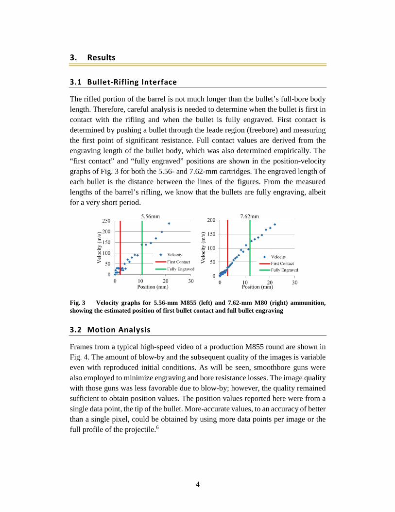
The rifled portion of the barrel is not much longer than the bullet’s full-bore body length. Therefore, careful analysis is needed to determine when the bullet is first in contact with the rifling and when the bullet is fully engraved. First contact is determined by pushing a bullet through the leade region (freebore) and measuring the first point of significant resistance. Full contact values are derived from the engraving length of the bullet body, which was also determined empirically. The “first contact” and “fully engraved” positions are shown in the position-velocity graphs of Fig. 3 for both the 5.56- and 7.62-mm cartridges. The engraved length of each bullet is the distance between the lines of the figures. From the measured lengths of the barrel’s rifling, we know that the bullets are fully engraving, albeit for a very short period.
Fig. 3 Velocity graphs for 5.56-mm M855 (left) and 7.62-mm M80 (right) ammunition, showing the estimated position of first bullet contact and full bullet engraving
3.2 Motion Analysis
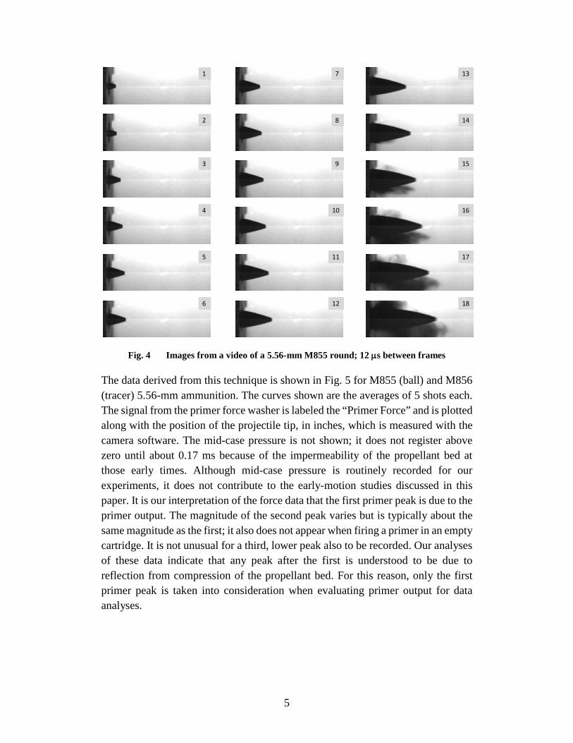
Frames from a typical high-speed video of a production M855 round are shown in Fig. 4. The amount of blow-by and the subsequent quality of the images is variable even with reproduced initial conditions. As will be seen, smoothbore guns were also employed to minimize engraving and bore resistance losses. The image quality with those guns was less favorable due to blow-by; however, the quality remained sufficient to obtain position values. The position values reported here were from a single data point, the tip of the bullet. More-accurate values, to an accuracy of better than a single pixel, could be obtained by using more data points per image or the full profile of the projectile.6
5
Fig. 4 Images from a video of a 5.56-mm M855 round; 12 µs between frames
The data derived from this technique is shown in Fig. 5 for M855 (ball) and M856 (tracer) 5.56-mm ammunition. The curves shown are the averages of 5 shots each. The signal from the primer force washer is labeled the “Primer Force” and is plotted along with the position of the projectile tip, in inches, which is measured with the camera software. The mid-case pressure is not shown; it does not register above zero until about 0.17 ms because of the impermeability of the propellant bed at those early times. Although mid-case pressure is routinely recorded for our experiments, it does not contribute to the early-motion studies discussed in this paper. It is our interpretation of the force data that the first primer peak is due to the primer output. The magnitude of the second peak varies but is typically about the same magnitude as the first; it also does not appear when firing a primer in an empty cartridge. It is not unusual for a third, lower peak also to be recorded. Our analyses of these data indicate that any peak after the first is understood to be due to reflection from compression of the propellant bed. For this reason, only the first primer peak is taken into consideration when evaluating primer output for data analyses.
1
6
2
3
4
5
7
12
8
9
10
11
13
18
14
15
16
17

6
Fig. 5 Data averaged from 5 shots showing position-time values for M855 and M856
There are 2 options for further analysis of the position data. The first option is to fit the data to a reasonable mathematical model or analytical expression. If available for the motion’s behavior, fitting the data to that expression and evaluating first and second derivatives (velocity and acceleration, respectively) would result in the most useful data for evaluations and comparisons. As will be discussed, this approach proved to be difficult, perhaps because the motion is caused by 2 forces, the primer output and the subsequent burning propellant.
The alternative is to fit the position data to a polynomial, typically of the sixth order. While the results of this approach are not as well-behaved, they are generally adequate within the range of the data being analyzed. For our purposes, a polynomial was fit to velocity values that were derived by taking simple differences of the position data. The analytical derivative of this polynomial then provided the acceleration values.
Starting with the M855 position data of Fig. 5, the velocity derived from simple differences is displayed in Fig. 6 as red squares. The early velocity imparted from the primer is clearly seen as distinct prior to further acceleration due to the burning propellant, which starts at about 0.17 ms. Figure 5 also shows the acceleration values for these data, which are displayed as discrete points as calculated from differences in the velocity points. Finally, Fig. 5 shows the calculated acceleration required to produce the observed velocity as represented by the solid blue line. This

7
calculated acceleration is the derivative of a polynomial function fitted to the derived velocity. The final results are essentially the same from both methods— simple differences and polynomial fit.
Fig. 6 Some calculated parameters for the M855 data of Fig. 5 derived from position data
This analysis can also be taken a further step to calculate the pressure that would be required to produce the observed acceleration using the mass and dimensions of the bullet. Or conversely, as shown in Fig. 7, the pressure required to produce the observed motion can be compared with the pressure that is calculated from the measured primer force washer using the primer cup dimensions. The difference in magnitudes of the (first) primer pressure spike and the inferred primer pressure from motion is probably not as important as their respective areas, as we will discuss in Section 3.4 of this report. Figure 7 does show the fundamental agreement obtained with fairly unsophisticated curve fitting and analysis. The differences between the values in Fig. 7 are much smaller than the differences produced from variation in propellant and bullet properties such as between an M855 and the newer M855A1.
Velocity from primer

8
Fig. 7 Comparison of pressure calculated from the primer force values and the pressure required to produce the observed motion
3.3 Observations of Bullet Motion between Rifled and Smoothbore Barrels
Smoothbore guns were constructed for both 5.56- and 7.62-mm cartridges for comparison with rifled barrels to provide better estimates of the engraving force. The bore diameter for the barrels are 5.77 and 7.87 mm, respectively. There was more blow-by in these barrels but most image sequences were sufficiently clear to allow proper measurements. As before, the fundamental data are the position versus time with the pressure record calculated from the primer force washer. From the known mass of the M855 projectile (62 gr or 0.00402 kg) and the velocity fitted to a smooth function (similar to that shown in Fig. 6), the kinetic energy can be calculated as a function of time or position. Similarly, using the pressure from the primer force measurement and the known area of the bullet base, the work done on the bullet can be calculated.
A key assumption in these calculations is that the pressure is equal at the primer pocket and the base of the bullet (i.e., the propellant bed acts as an incompressible fluid when initially acted upon by the primer output). Plotted versus time, it is clear that the smoothbore bullet moves faster, but, plotted versus position, the bullet from smoothbore and rifled barrels have almost the same energy and work values after 20 mm of travel. The values for an M855 in a standard rifled and smoothbore barrel are shown at Fig. 8. More careful examination of the kintic energey data (Fig. 9)
9
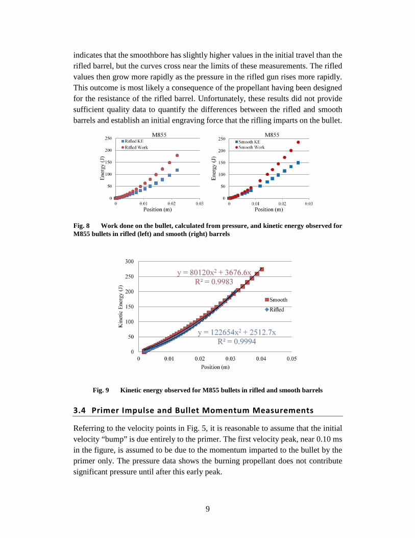
indicates that the smoothbore has slightly higher values in the initial travel than the rifled barrel, but the curves cross near the limits of these measurements. The rifled values then grow more rapidly as the pressure in the rifled gun rises more rapidly. This outcome is most likely a consequence of the propellant having been designed for the resistance of the rifled barrel. Unfortunately, these results did not provide sufficient quality data to quantify the differences between the rifled and smooth barrels and establish an initial engraving force that the rifling imparts on the bullet.
Fig. 8 Work done on the bullet, calculated from pressure, and kinetic energy observed for M855 bullets in rifled (left) and smooth (right) barrels
Fig. 9 Kinetic energy observed for M855 bullets in rifled and smooth barrels
3.4 Primer Impulse and Bullet Momentum Measurements
Referring to the velocity points in Fig. 5, it is reasonable to assume that the initial velocity “bump” is due entirely to the primer. The first velocity peak, near 0.10 ms in the figure, is assumed to be due to the momentum imparted to the bullet by the primer only. The pressure data shows the burning propellant does not contribute significant pressure until after this early peak.
10
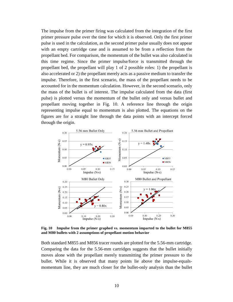
The impulse from the primer firing was calculated from the integration of the first primer pressure pulse over the time for which it is observed. Only the first primer pulse is used in the calculation, as the second primer pulse usually does not appear with an empty cartridge case and is assumed to be from a reflection from the propellant bed. For comparison, the momentum of the bullet was also calculated in this time regime. Since the primer impulse/force is transmitted through the propellant bed, the propellant will play 1 of 2 possible roles: 1) the propellant is also accelerated or 2) the propellant merely acts as a passive medium to transfer the impulse. Therefore, in the first scenario, the mass of the propellant needs to be accounted for in the momentum calculation. However, in the second scenario, only the mass of the bullet is of interest. The impulse calculated from the data (first pulse) is plotted versus the momentum of the bullet only and versus bullet and propellant moving together in Fig. 10. A reference line through the origin representing impulse equal to momentum is also plotted. The equations on the figures are for a straight line through the data points with an intercept forced through the origin.
Fig. 10 Impulse from the primer graphed vs. momentum imparted to the bullet for M855 and M80 bullets with 2 assumptions of propellant motion behavior
Both standard M855 and M856 tracer rounds are plotted for the 5.56-mm cartridge. Comparing the data for the 5.56-mm cartridges suggests that the bullet initially moves alone with the propellant merely transmitting the primer pressure to the bullet. While it is observed that many points lie above the impulse-equals-momentum line, they are much closer for the bullet-only analysis than the bullet

11
and propellant analysis. For the 7.62-mm graph, the data are more widely scattered. From the limited M80 samples, it might be concluded that the propellant and bullet move together as opposed to the 5.56-mm configuration where only the bullet is moving. The difference may be the consequence of the primer mismatch when comparing output versus cartridge volume and propellant charge. While the 7.62-mm cartridge has considerably more volume (~75%), the large rifle primer output is on the same scale as the small rifle primer. Furthermore, the 7.62-mm cartridge has a little more ullage than the 5.56-mm cartridge, affording the propellant greater freedom of motion. It is clear that more measurements are needed in both cartridges before any statistically valid conclusion can be reached.
3.5 Further Demonstrations of Primer Brisance
Two different cartridge configurations were explored to demonstrate the dominant force that the primer exerts on the bullet during the early part of the interior ballistic cycle. Two of the most interesting observations were made with the smoothbore barrel. The major ballistic difference occurs when the bullet would normally engage the rifling. From the contact position of Fig. 3 and the acceleration of Fig. 6, the acceleration drops but does not quite reach a value of zero when the rifling is initially engaged. The delay between the primer discharge and the beginning of bullet motion is attributed to the limited sound speed through the propellant bed. All of this appears to be consistent with the primer debulleting the round and at least initially engaging the rifling.
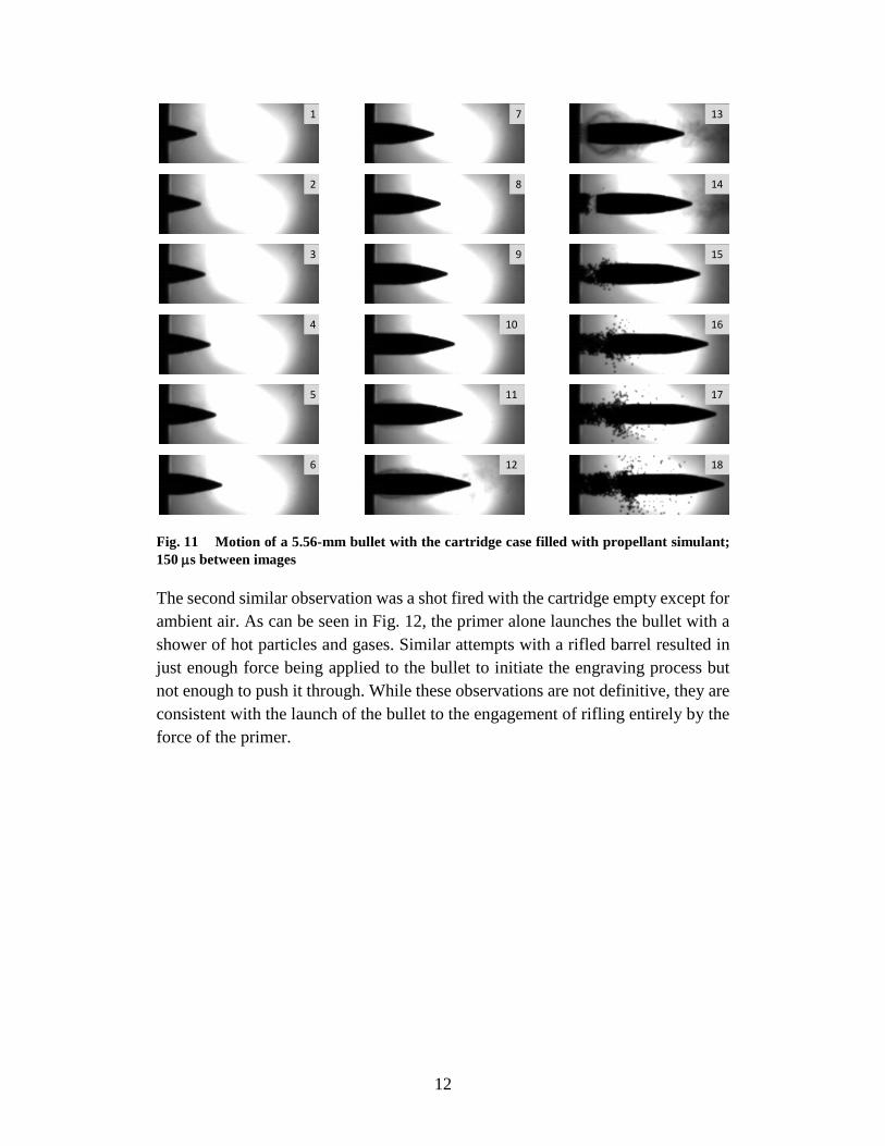
The first of these observations was done with polystyrene balls of approximately the diameter of the normal ball powder used as a propellant simulant. The simulant was loaded to maximum case capacity; however, it does not duplicate the mechanical properties of the propellant and has a lower flow density. The bullet velocity was greatly reduced and the frame rate is slower, as noted in the figure caption. Of particular interest is the 14th frame of Fig. 11: Note the separation between the propellant simulant and the bullet. This appears to show that the primer compressed the propellant simulant against the bullet and then launched it. This initial contact apparently results in an inelastic collision with the propellant and the projectile moving in opposite directions. Shortly thereafter, the propellant catches up with the projectile and is seen to be moving much faster than the projectile outside the gun.
12
Fig. 11 Motion of a 5.56-mm bullet with the cartridge case filled with propellant simulant; 150 µs between images
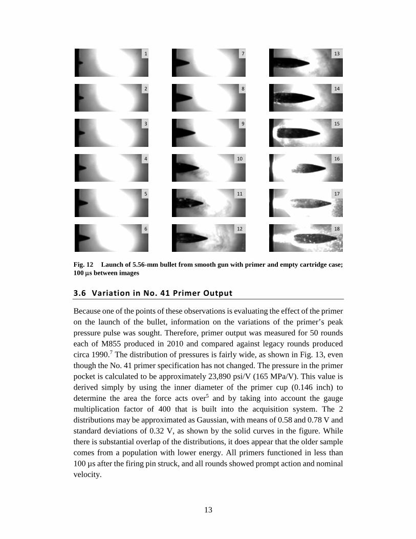
The second similar observation was a shot fired with the cartridge empty except for ambient air. As can be seen in Fig. 12, the primer alone launches the bullet with a shower of hot particles and gases. Similar attempts with a rifled barrel resulted in just enough force being applied to the bullet to initiate the engraving process but not enough to push it through. While these observations are not definitive, they are consistent with the launch of the bullet to the engagement of rifling entirely by the force of the primer.
1
2
3
4
5
6
7
8
9
10
11
12
13
14
15
16
17
18
13
Fig. 12 Launch of 5.56-mm bullet from smooth gun with primer and empty cartridge case; 100 µs between images
3.6 Variation in No. 41 Primer Output
Because one of the points of these observations is evaluating the effect of the primer on the launch of the bullet, information on the variations of the primer’s peak pressure pulse was sought. Therefore, primer output was measured for 50 rounds each of M855 produced in 2010 and compared against legacy rounds produced circa 1990.7 The distribution of pressures is fairly wide, as shown in Fig. 13, even though the No. 41 primer specification has not changed. The pressure in the primer pocket is calculated to be approximately 23,890 psi/V (165 MPa/V). This value is derived simply by using the inner diameter of the primer cup (0.146 inch) to determine the area the force acts over5 and by taking into account the gauge multiplication factor of 400 that is built into the acquisition system. The 2 distributions may be approximated as Gaussian, with means of 0.58 and 0.78 V and standard deviations of 0.32 V, as shown by the solid curves in the figure. While there is substantial overlap of the distributions, it does appear that the older sample comes from a population with lower energy. All primers functioned in less than 100 µs after the firing pin struck, and all rounds showed prompt action and nominal velocity.
1
2
3
4
5
6
13
14
15
16
17
18
7
8
9
10
11
12
14
Fig. 13 Histogram of the measured first peak height for No. 41 primers in 2 lots of M855 ammunition
4. Future Studies
The quality of the position-time data could be improved in at least 2 ways. One improvement would be to increase the frame rate, perhaps approaching twice the present rate. Measuring the position with more than just the bullet tip, such as employing a profile measurement technique, could result in increased precision. A compromise between full image fitting and using multiple points from each image will be explored.
The use of polynomials to fit motion or velocity has been marginally acceptable, but the behavior near the beginning of motion is sometimes not well described. Fitting the data to a more appropriate mathematical expression and then evaluating derivatives would result in the smoothest subsequent derivatives. Fitting the motion with a complex function that better duplicates the known behavior (primer and then propellant) will be pursued. One example, which was labor-intensive and not practical, was done once (Anthony J Kotlar, ARL, 2013, private communication, unreferenced) with results that are shown in Fig. 14. In this example, the position-time data were fitted to a smooth line followed by subsequent derivatives. Some effort toward developing more-automated computer analyses with this level of smoothness will be considered.

15
Fig. 14 Areas of future studies; improved data fit of position with derivatives in uncalibrated units
In studying the videos of these events, it is clear that the bullets can have considerable off-axis motion. Some preliminary data have been obtained (Daniel R Gubernat, US Army Armament Research, Development and Engineering Center, 2013, private communication, unreferenced) such as that shown in Fig. 15 for M80 7.62-mm production rounds. The plot illustrates the off-axis motion of 4 different shots as measured at the projectile tip. Experiments to study and understand the implications of this motion to accuracy are being discussed.
Fig. 15 Four discrete measurements of M80 off-axis motion
5. Conclusions
By employing short-barrel guns, high-speed imaging, and the ARL primer force breech, extensive evaluations have been made into the initial motion, velocity, and acceleration of small-caliber projectiles in both 5.56 and 7.62 mm. These studies have shown that the primer output alone can greatly influence the initial motion of a small-caliber projectile. The primer is capable of producing enough force to
16
debullet the projectile and begin the engraving process prior to any significant propellant burning. The timing of the projectile’s initial motion relative to primer output and propellant ignition is vital to IB models. These initial conditions set the stage for subsequent propellant gas generation and IB performance characteristics. From impulse and momentum measurements associated with the primer output, it was determined that the manner in which the primer force is transmitted through the propellant bed is dependent on the specific cartridge being investigated. It appears that the amount of ullage is the driving mechanism that influences the primer force transmission mode. The ullage provides a certain amount of freedom for the propellant bed to compress and move during the initial stages of the interior ballistic event. With minimal ullage available, the propellant merely transmits the primer force to the projectile, acting much like an incompressible fluid. Conversely, a cartridge with more ullage will create a situation where the initial motion of projectile and propellant act more in unison.
The work and kinetic energy of the projectile was studied in an attempt to quantify initial bore resistance and engraving forces. This was investigated by employing a smoothbore barrel to measure differences from a rifled barrel. Values of work done and kinetic energy at similar distances of the 2 barrels yielded nearly identical values. Therefore, a conclusive quantified value on initial engraving forces cannot be determined from the data recorded.
Finally, all the information gathered from these experiments will be discussed with the IB modelers. Discussions will elucidate which specific data generated can be incorporated into current models, as well as areas where better data is needed. The ultimate goal is to generate more-robust models that will more accurately predict the IB events occurring within a small-caliber cartridge. This is particularly challenging because, as shown through the course of these experiments, shot-to-shot parameters that we can measure vary in detail even when the overall IB process results in a tightly distributed muzzle velocity.

17
6. References
1. Horst, AW, Conroy PJ. Flame-spreading processes in a small-caliber gun. Aberdeen Proving Ground (MD): Army Research Laboratory (US); 2007 July. Report No.: ARL-TR-4181. Also available at: http://www.arl.army.mil/arlreports/2007/ARL-TR-4181.pdf.
2. Beyer RA, Colburn JW. Primer force and chamber pressure measurements at 5.56-mm caliber. Presented at the 26th International Symposium on Ballistics; 2011 Sep 12–16; Miami, FL.
3. Ritter JJ. Characterizing 5.56-mm cartridge performance with novel measurement techniques. Journal of Energetic Materials and Chemical Propulsion. 2013;12(4):361–370.
4. Cup, primer (No. 34). Picatinny Arsenal (NJ): Armament Research, Development and Engineering Center; 1991 Dec. Drawing No.: 8594095, Revision J.
5. Cup, primer (No. 41). Picatinny Arsenal (NJ): Armament Research, Development and Engineering Center; 1999 Jan. Drawing No.: 1053280, Revison G.
6. Beyer RA, Kotlar AJ, Beyer MR. 1991. Application of digital measurement techniques to analysis of range shadowgraphs. Aberdeen Proving Ground (MD): Ballistics Research Laboratory (US); 1991. Report No.: BRL-TR-3271.
7. Ritter JJ, Beyer RA, Canami A. Characterization of 5.56-mm cartridge propellants with ullage. Aberdeen Proving Ground (MD): Army Research Laboratory (US); 2012 July. Report No.: ARL-TR-6045.

18
List of Symbols, Abbreviations, and Acronyms
ARL US Army Research Laboratory
fps frames per second
gr grain
J Joule
IB interior ballistics
in inch
kg kilogram
km/s2 kilometer per second squared
ksi thousand pounds per square inch
m meter
mm millimeter
MPa MegaPascal
ms millisecond
m/s meters per second
No. number
N-s Newton second
psi pounds per square inch
µs microsecond
V volt

19
1 DEFENSE TECHNICAL (PDF) INFORMATION CTR DTIC OCA 2 DIRECTOR (PDF) US ARMY RESEARCH LAB RDRL CIO LL IMAL HRA MAIL & RECORDS MGMT 1 GOVT PRINTG OFC (PDF) A MALHOTRA 4 COMMANDER (PDF) US ARMY ARDEC RDAR MEE W E CARAVACA L LOPEZ K LUHMANN M KAUFFMAN 6 COMMANDER (PDF) US ARMY ARDEC RDAR MEM I G DEROSA D GUBERNAT M VOLKMANN A ISMAILOV J MIDDLETON M MINISI 1 COMMANDER (PDF) US ARMY ARDEC RDAR MEM M NICOLICH 1 COMMANDER (PDF) US ARMY ARDEC RDAR MEE W S NICOLICH 1 COMMANDER (PDF) US ARMY ARDEC RDAR MEE P J WYCKOFF 4 PM MAS (PDF) SFAE AMO MAS SMC R KOWALSKI F HANZL P RIGGS J LUCID
3 ST MARKS POWDER (PDF) A GENERAL DYNAMICS CO J M HOWARD C MEYERS R PULVER 3 ATK SMALL CALIBER SYS (PDF) J BROWN M HAFNER G WINTER 30 DIR USARL (PDF) RDRL WM B FORCH S KARNA RDRL WML M ZOLTOSKI RDRL WML A W OBERLE RDRL WML B N TRIVEDI RDRL WML C S AUBERT RDRL WML D R BEYER A BRANT C CHEN A CANAMI J COLBURN P CONROY T DUTTON S HOWARD M MCQUAID M NUSCA J RITTER J SCHMIDT J VEALS A WILLIAMS Z WINGARD RDRL WML E P WEINACHT RDRL WML F M ILG RDRL WML G T BROSSEAU A MICHLIN J SOUTH RDRL WML H T EHLERS T FARRAND L MAGNESS J NEWILL

20
INTENTIONALLY LEFT BLANK.