Embed Size (px)
Citation preview

Reference Manual – English
PRIMERGY BX400 Blade Server Systems Contents of the MMB S1 Help System December 2010

Certified documentation according to DIN EN ISO 9001:2008 To ensure a consistently high quality standard and user-friendliness, this documentation was created to meet the regulations of a quality management system which complies with the requirements of the standard DIN EN ISO 9001:2008.
cognitas. Gesellschaft für Technik-Dokumentation mbH www.cognitas.de
Copyright and Trademarks Copyright © 2010 Fujitsu Technology Solutions GmbH.
All rights reserved. Delivery subject to availability; right of technical modifications reserved.
All hardware and software names used are trademarks of their respective manufacturers.
Delivery subject to availability; right of technical modifications reserved. All hardware and software names used are trade names and/or trademarks of their respective manufacturers.
The contents of this manual may be revised without prior notice.
Fujitsu assumes no liability for damages to third party copyrights or other rights arising from the use of any information in this manual.
No part of this manual may be reproduced in any form without the prior written permission of Fujitsu.
Microsoft, Windows, Windows Server, and Hyper V are trademarks or registered trademarks of Microsoft Corporation in the USA and other countries.
Intel and Xeon are trademarks or registered trademarks of Intel Corporation or its subsidiaries in the USA and other countries.
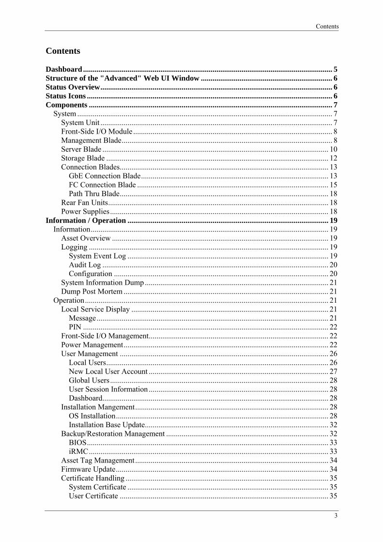
Contents
Contents Dashboard ................................................................................................................................. 5 Structure of the "Advanced" Web UI Window .................................................................... 6 Status Overview........................................................................................................................ 6 Status Icons ............................................................................................................................... 6 Components .............................................................................................................................. 7
System .................................................................................................................................... 7 System Unit ........................................................................................................................ 7 Front-Side I/O Module ....................................................................................................... 8 Management Blade............................................................................................................. 8 Server Blade ..................................................................................................................... 10 Storage Blade ................................................................................................................... 12 Connection Blades............................................................................................................ 13
GbE Connection Blade................................................................................................. 13 FC Connection Blade ................................................................................................... 15 Path Thru Blade............................................................................................................ 18
Rear Fan Units.................................................................................................................. 18 Power Supplies................................................................................................................. 18
Information / Operation ........................................................................................................ 19 Information........................................................................................................................... 19
Asset Overview ................................................................................................................ 19 Logging ............................................................................................................................ 19
System Event Log ........................................................................................................ 19 Audit Log ..................................................................................................................... 20 Configuration ............................................................................................................... 20
System Information Dump ............................................................................................... 21 Dump Post Mortem .......................................................................................................... 21
Operation.............................................................................................................................. 21 Local Service Display ...................................................................................................... 21
Message........................................................................................................................ 21 PIN ............................................................................................................................... 22
Front-Side I/O Management............................................................................................. 22 Power Management.......................................................................................................... 22 User Management ............................................................................................................ 26
Local Users................................................................................................................... 26 New Local User Account ............................................................................................. 27 Global Users................................................................................................................. 28 User Session Information ............................................................................................. 28 Dashboard..................................................................................................................... 28
Installation Mangement.................................................................................................... 28 OS Installation.............................................................................................................. 28 Installation Base Update............................................................................................... 32
Backup/Restoration Management .................................................................................... 32 BIOS............................................................................................................................. 33 iRMC............................................................................................................................ 33
Asset Tag Management .................................................................................................... 34 Firmware Update.............................................................................................................. 34 Certificate Handling ......................................................................................................... 35
System Certificate ........................................................................................................ 35 User Certificate ............................................................................................................ 35
3

Contents
Settings .................................................................................................................................... 36 System unit ........................................................................................................................... 36
Network Interface............................................................................................................. 36 Service LAN................................................................................................................. 36 Management LAN........................................................................................................ 36
SNMP............................................................................................................................... 39 Alerting............................................................................................................................. 39 Date/Time......................................................................................................................... 40
Refresh Settings.................................................................................................................... 41 Language .............................................................................................................................. 41 Base Configuration Wizard.................................................................................................. 41
Rack ......................................................................................................................................... 42 VIOM Manager ...................................................................................................................... 42
4
Dashboard
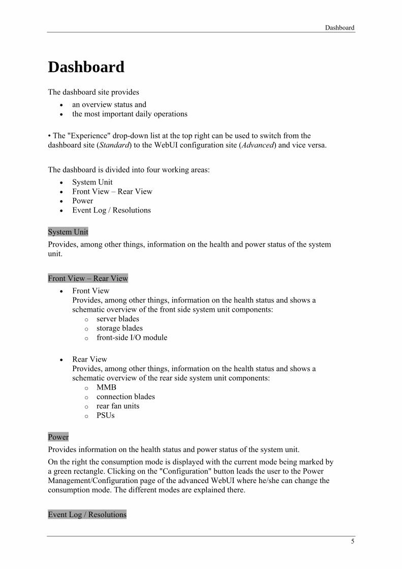
Dashboard The dashboard site provides
• an overview status and • the most important daily operations
• The "Experience" drop-down list at the top right can be used to switch from the dashboard site (Standard) to the WebUI configuration site (Advanced) and vice versa. The dashboard is divided into four working areas:
• System Unit • Front View – Rear View • Power • Event Log / Resolutions
System Unit Provides, among other things, information on the health and power status of the system unit. Front View – Rear View
• Front View Provides, among other things, information on the health status and shows a schematic overview of the front side system unit components:
o server blades o storage blades o front-side I/O module
• Rear View Provides, among other things, information on the health status and shows a schematic overview of the rear side system unit components:
o MMB o connection blades o rear fan units o PSUs
Power Provides information on the health status and power status of the system unit. On the right the consumption mode is displayed with the current mode being marked by a green rectangle. Clicking on the "Configuration" button leads the user to the Power Management/Configuration page of the advanced WebUI where he/she can change the consumption mode. The different modes are explained there. Event Log / Resolutions
5
Structure of the "Advanced" Web UI Window
Provides a table with the newest 10 event log entries from the MMB and the server blades.
Structure of the "Advanced" Web UI Window The Web UI window comprises a total of 5 frames:
1. Banner Frame 2. Status Frame 3. Navigation Frame
This frame consists of a Front View, a Rear View and the Navigation Tree. When you have selected a component in the Navigation Tree, you are offered an associated help text via Help → On Page (top right in the Banner Frame).
4. Main Frame 5. Bottom Frame
Details of the content of the various frames are provided in the User Guide PRIMERGY BX400 Blade Server Systems.
Notes:
You get back from a selected help text to this overview in various ways: by right-clicking the particular page and using the Back option, or simply by striking the backspace key.
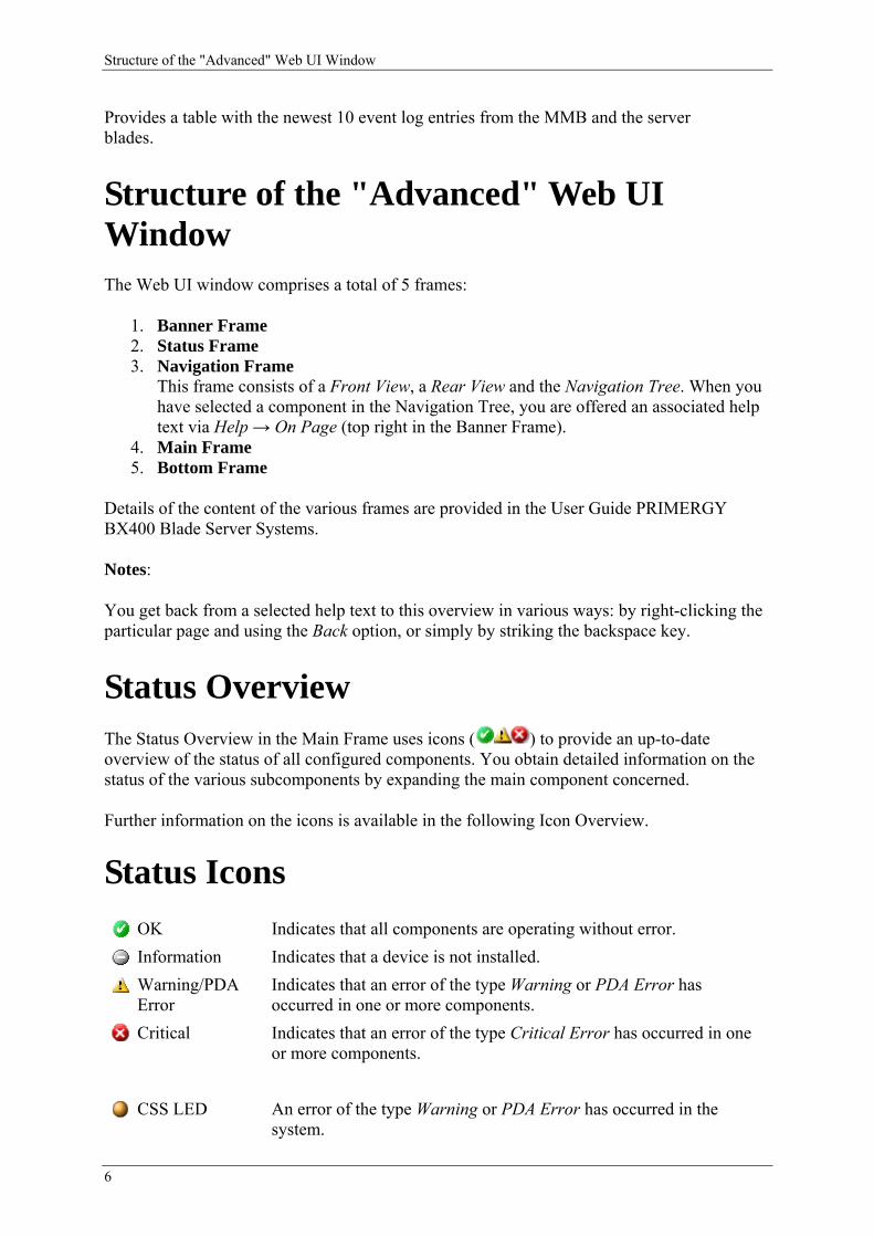
Status Overview The Status Overview in the Main Frame uses icons ( ) to provide an up-to-date overview of the status of all configured components. You obtain detailed information on the status of the various subcomponents by expanding the main component concerned.
Further information on the icons is available in the following Icon Overview.
Status Icons OK Indicates that all components are operating without error.
Information Indicates that a device is not installed.
Warning/PDA Error
Indicates that an error of the type Warning or PDA Error has occurred in one or more components.
Critical Indicates that an error of the type Critical Error has occurred in one or more components.
CSS LED An error of the type Warning or PDA Error has occurred in the system.
6
Components
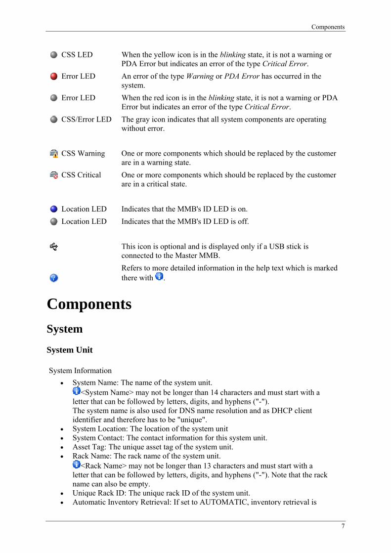
CSS LED When the yellow icon is in the blinking state, it is not a warning or PDA Error but indicates an error of the type Critical Error.
Error LED An error of the type Warning or PDA Error has occurred in the system.
Error LED When the red icon is in the blinking state, it is not a warning or PDA Error but indicates an error of the type Critical Error.
CSS/Error LED The gray icon indicates that all system components are operating without error.
CSS Warning One or more components which should be replaced by the customer are in a warning state.
CSS Critical One or more components which should be replaced by the customer are in a critical state.
Location LED Indicates that the MMB's ID LED is on.
Location LED Indicates that the MMB's ID LED is off.
This icon is optional and is displayed only if a USB stick is connected to the Master MMB.
Refers to more detailed information in the help text which is marked there with .
Components System
System Unit
System Information • System Name: The name of the system unit.
<System Name> may not be longer than 14 characters and must start with a letter that can be followed by letters, digits, and hyphens ("-"). The system name is also used for DNS name resolution and as DHCP client identifier and therefore has to be "unique".
• System Location: The location of the system unit • System Contact: The contact information for this system unit. • Asset Tag: The unique asset tag of the system unit. • Rack Name: The rack name of the system unit.
<Rack Name> may not be longer than 13 characters and must start with a letter that can be followed by letters, digits, and hyphens ("-"). Note that the rack name can also be empty.
• Unique Rack ID: The unique rack ID of the system unit. • Automatic Inventory Retrieval: If set to AUTOMATIC, inventory retrieval is
7
Components
performed automatically for the server blades which are inserted or when the system unit is powered on. If set to MANUAL, automatic inventory retrieval is not performed.
• Update All Connection Blade Names On Changing System Name or Rack Name: When this function is enabled, the names of all connection blades are updated in accordance with the following syntax:
<Rack Name>–<System Name>–CB<Slot Number> This only affects the types "GbE Connection Blade-x" and "10GbE Connection Blade-x". Other types of connection blade are not affected by this function.
Fan Control • Here the status of all fans in the system unit is displayed.
All Fans Have Failed • Enables the user to configure the reaction after all fans have failed or are
unavailable.
Fan Test • Daily test time: Sets the fan test time for the system fan. The format should be
HH:MM. • Test at every startup: Sets the fan behavior when the system powers on. If this
function is checked, all the fans present will rotate at full speed for a while.
Temperature Sensor Control • Enables the user to configure what action will be taken when the system unit's
temperature sensor is in a critical state.
Front-Side I/O Module
Provides product information on the front-side I/O module. The front-side I/O module can be assigned to a server blade. Clicking the corresponding link USB/DVD Assignment opens the "Front-Side I/O Management" page.
Management Blade
Information • Blade Information
o Play Role: The management blade plays the role of the master to handle server management or of a slave for standby.
o Status: Displays the current status of the management blade. o Manufacturer: Displays management blade production information. o Production Date: Displays the management blade production date. o Serial Number: Displays the management blade serial number. o Product Name: Displays the management blade product name.
8
Components
o Model Name: Displays the management blade model name. o Management LAN MAC Address: Physical address (MAC address) of
the management LAN interface of the MMB. o Management LAN IP Address: IP address of the management LAN
interface of the MMB. o Firmware Version: Displays the management blade management
firmware version. o Hardware Version: Displays the management blade hardware version. o Service LAN MAC Address: Physical address (MAC address) of the
service LAN interface of the MMB. o Service LAN IP Address: IP address of the service LAN interface of the
MMB. • Voltage Information
o Voltage Status: Displays the voltage status of the management blade. o Maximum Voltage Value: Displays the maximum voltage value of the
management blade. o Minimum Voltage Value: Displays the minimum voltage value of the
management blade. o Normal Voltage Value: Displays the normal voltage value of the
management blade. o Current Voltage Value: Displays the current voltage value of the
management blade.
Event Log Displays all system events and can be filtered by component and severity by selecting filtering factors and clicking the "Apply" button.
• Event Log Filter o Severity: You can select the events to be displayed (All Events,
Informational, Major, Minor, or Critical).
All event entries in the event log are cleared by clicking the "Clear All Entries" button.
• Event Log Content o Time stamp: Year-Month-Day HH:MM:SS. o Severity: Informational, Major, Minor, or Critical. o Description: Message description.
Configuration
• Reboot Management Blade: The submit button will show "Reboot" when there is only one MMB present.
• Switch Management Role: When a slave MMB is present, the "Switch Role" button is enabled.
o Switch Role on NIC Status Detection: Enables/disables NIC status detection.
o Link Down Timeout (0-300): Defines a timeout (0-300 seconds) for NIC status detection when the timeout is reached; the master and slave MMB
9
Components
then switch roles (if the slave is ok).
Backup/Restoration Backup Configuration
• Backup Media: Click the radio button to choose the backup media. • Memory/USB Backup File: The backup path and filename will be displayed
here. • Memory/USB Backup Status: Shows the memory/USB backup status.
Restore Configuration • Backup Media: Click the radio button to choose the source media. • Memory/USB Backup Files: Select available source files from memory/USB. • Local Backup Files: Choose a source file from the local file system. • Restoration Status: Shows whether or not restoration is in progress. If
restoration is successful, the MMB will reboot automatically.
Server Blade
Information Blade Asset Information
• Manufacturer: Displays the manufacturer of the server blade. • Product Model: Displays the server blade product model name. • Product Name: Displays the server blade product name. • Product Version: Displays the server blade product version. • Model Name: Displays the product part number. • Serial Number: Displays the server blade serial number. • Identification Serial Number: Displays the identification serial number. • Firmware Version: Displays the server blade iRMC firmware version. • Hardware Version: Displays the server blade hardware version. • Production Date: Displays the server blade production date. • Active GUID: Displays the active GUID. • Manufacturer GUID: Displays the manufacturer GUID. • Mezzanine Card: Displays whether a Mezzanine card is installed or not.
Operating System Information • OS Type: Displays the OS platform currently running on the server blade. • OS Version: Displays the OS version currently running on the server blade. • BIOS Version: Displays the server blade BIOS version.
CPU Information Displays CPU processor information including type, speed, CPU stepping, and socket type.
Memory Information
10
Components
Displays memory module information and configuration. Network Card Information / FibreChannel Card Information / Infiniband Card Information Displays information like MAC address/WWPN/Port GUID, IP address/WWNN, NIC type, BIOS enabled, ekeying enabled and information about the associated connection blades.
Event Log Displays all system events and can be filtered by component and severity by selecting filtering factors and clicking the "Apply" button.
• Event Log Filter o Severity: You can select the events to be displayed (All Events,
Informational, Major, Minor, or Critical).
All event entries in the event repository are cleared by clicking the "Clear All Entries" button.
• Event Log Content o Time stamp: Year-Month-Day HH:MM:SS. o Severity: Informational, Major, Minor, or Critical. o Description: Message description.
Power Management Server Blade Power Control
o Power Control Mode: Shows the mode of the selected server blade. There are three modes:
Minimum: The most efficient power consumption behavior is set via the iRMC.
Best Performance: The iRMC sets the system's power consumption behavior optimally with regard to performance.
Disabled: The iRMC has no option to set the system's power consumption behavior. This can, for example, be the case when the server blade is in standby status (no system boot) or when an OS which offers no power management support (e.g. DOS) was loaded.
o Power Status: The user can execute turn-on and shutdown actions of the server blade. There are 6 options available.
power on: Turns on the server blade power. graceful shutdown and off: Shuts down the operating system and
turns off the server blade. graceful shutdown and power cycle: First shuts down the
operating system, then turns off the server blade, and after a delay turns it on again.
hard reset: Resets the server blade. NMI: Generates a nonmaskable interrupt. hard power off: Turns off the system power, which is equivalent
11
Components
to pressing the power button.
Server Blade Power Option
o Power Restore Policy: Sets the behavior of the server blade after AC Fail.
Configuration • ASR (Automatic Server Restart): Enables/disables the Boot Watchdog timer and
configures the action when it times out. • Boot Options: Selects the server blade LAN port for a PXE boot. • Host Name: The user can enter a host name here which is also contained in the
SNMP. If the ServerView agents are installed on the server blade, the MMB takes
over the OS host name. • iRMC Address Configuration: Permits the address configuration of the
associated iRMC. The "Activate Service Session" button enables you to back up the current iRMC LAN parameters. You can restore these with "Deactivate Service Session".
• Mezzanine-2 MUX Configuration: This box enables the Mezzanine Card (Quad-Port Ethernet) in slot 2 of the server blade to be switched from the default value bays 7/8 to bays 5/6 or 5/6/7/8.
The multiplexer (MUX for short) of this Mezzanine Card has four ports. With the default, two ports (dual) lead to bay 7 and two to bay 8. These ports can be switched over in pairs to bays 5/6 or singly to bay 5/6/7/8.
• Power Setting: If the "Force Power-Off" control box is enabled and graceful shutdown of the server blade fails, it is shut down by means of a hard power-off after a specifiable time (1 to 7 minutes).
• Power On/Off Time: The user can set up a power on/off schedule for the server blade.
Backup/Restoration • CMOS Backup: Backup of the server blade BIOS parameters. The server blade
must be powered on before backup/restoration can take place. If this is successful, the backup file will be displayed in a CMOS file selecting table.
• CMOS Restoration: Selects the CMOS file and restoration policy to restore the server blade parameters. If the smart-restore option is selected, it will be restored with verified MAC address, slot ID and BIOS version.
Storage Blade
Blade Asset Information • Manufacturer: Displays the manufacturer of the storage blade. • Product Name: Displays the storage blade product name. • Product Model: Displays the storage blade product model name.
12
Components
• Part Number: Displays the storage blade part number. • Serial Number: Displays the storage blade serial number. • Product Version: Displays the storage blade product version. • Production Date: Displays the storage blade production date. • Hardware Version: Displays the storage blade hardware version.
• Associated Server Blades o Left-hand Side: The adjacent server blade on the left-hand side. o Right-hand Side: The adjacent server blade on the right-hand side.
Connection Blades
GbE Connection Blade Information
• Blade Information o Manufacturer: Displays manufacturer information. o Production Date: Displays the production date. o Serial Number: Displays the serial number. o Product Name: Displays the product name. o Model Name: Displays the model name. o Hardware Version: Displays the board version. o Firmware Version: Displays the management firmware version. o Firmware Mode: Displays the firmware mode. The blade types "10GbE
Connection Blade-x" and "GbE Connection Blade-x" can have the values "Switch" or "IBP".
The mode can be set via the connection blade's built-in command line interface or via the "Configuration" tab, "Firmware Mode Settings". Afterwards the blade has to be rebooted or reboots automatically.
o Stacking Status: For connection blades with the product name "Connection Blade GbE 36/8+2" only. Displays the stacking status ("Master" or "Member").
o Management Port MAC Address: Displays the MAC address of the connection blade's management port.
o Asset Tag: Displays the asset tag of the connection blade if it is defined. o Administrative URL: URL to link the connection blade's web home
page. For blades in stacking mode the URL of the master is displayed (for the members, too).
Power Management • Power Settings: The user can reset the blade after selecting the power action and
clicking the "Apply" button.
Configuration The current status of some parameters is queried using the "Refresh" button. This is necessary as the parameters can also be changed via the connection blade's own management functions. If no change is displayed after the button has been pressed, this means that the parameter has not been changed by the connection blade up to this point
13
Components
in time.
• User Assigned Name: Enter the connection blade's user assigned name. The user assigned name may not be longer than 31 characters and must start
with a letter that can be followed by letters, digits, and hyphens ("-"). Changing the rack name (via the menu item "System Unit" in the Web UI) may overwrite the here defined name (affects the types "GbE Connection Blade-x" and "10GbE Connection Blade-x" only). The connection blade takes the assigned name and uses it (if it was not overwritten) for the following system settings: 1.) Prompt name in the connection blade's built-in command line interface 2.) Port naming 3.) Host name 4.) DHCP client identifier
• Blade Asset Tag: Enter a unique asset tag for the connection blade. • Management Port Settings: Displays the connection blade's network setting
information. o Enable DHCP: Sets the IP mode (DHCP or NO-DHCP) for the
management IP settings of the connection blade. o DHCP Client Name: Set the DHCP client name for the connection blade.
It is only valid when DHCP is enabled. o IP Address / Subnet Mask / Gateway Address: Displays the connection
blade's management IP address / subnet mask / gateway address. • Stacking Port Setting: Enables/disables the internal stacking port (only in the
case of connection blades with the product name "BX900 Connection Blade GbE 36/8+2").
• Reset Interface Settings to Default: Resets the interface settings listed below to their default values:
o User Assigned Name: [<rack name>-]<enclosure name><last 6 digits of enclosure serial no.>-CB<bay no.> As default the <rack name> is empty.
o DHCP OOB: enabled o Internal Stacking Link: disabled o Port-Speed Settings: All ports will be set to 10 Gb/s
• Firmware Mode Settings: Some connection blades are able to boot different firmware modes. Changing the boot mode forces a reboot of the connection blade. Please refer to the corresponding connection blade manual for the detailed information about boot modes.
• Account Settings o Privileged Mode Password: Enter a password for the privileged mode of
the connection blade. o Login User Name: Enter the login user name for the connection blade's
web home page. o Login Password: Enter the login password for connection blade's web
home page.
Note: If the preconfigured user and password settings are changed via the connection blade's command line interface or WebUI, these login settings have to be made here, too. Otherwise the MMB is no longer able to access the connection blade.
14
Components
• Port Group Speed Settings (for 10 GbE Connection Blade-x only): Here you can set the transfer speed separately for port groups comprising three server bays each or uniformly for all server bays.
Backup/Restoration • Backup Configuration
o Backup Media: Here you select the medium on which the interface data between the MMB and the connection blade is to be backed up (Memory, USB or Local File).
o Memory/USB Backup File: You can change the name of the file containing the backed-up data here by clicking the "New Name" button. A new file name consisting of an identification tag and the current date is then generated.
o Memory/USB Backup Status: After you have clicked the "Backup" button, the status is displayed here. After the backup has been completed, you can click the "Refresh Status" button to return to the default status "Not Started".
• Restore Configuration o Backup Media: Here you select the medium from which the interface
data between the MMB and the connection blade is to be restored (Memory, USB or Local File).
o Memory/USB Backup Files: Here you can select the version which you wish to restore from all the versions which have been backed up so far.
o Local Backup Files: Offers you the option of searching for particular versions which have been backed up in local files.
o Restoration Status: After you have clicked the "Restore" button, the status is displayed here. After restoration has been completed, you can click the "Refresh Status" button to return to the default status "Not Started".
o View Configuration: Displays the current interface data between the MMB and the connection blade.
FC Connection Blade
Information • Blade Information
o Manufacturer: Displays manufacturer information. o Date Manufactured: Displays the production date. o Serial Number: Displays the serial number. o Product Name: Displays the product name. o Product Number: Displays the product number. o Hardware Version: Displays the board version. o Firmware Version: Displays the management firmware version. o Management Port MAC Address: Displays the MAC address. o WWN Address: Displays the WWN address for FC connection blade. o Firmware Mode: Displays the firmware mode. "8Gb FC Connection
Blade-x" can have the values "Access Gateway", "Native" or "Interop".
15

Components
The mode can be set via the connection blade's built-in command line interface or via the "Configuration" tab, "Firmware Mode Settings". Afterwards the blade has to be rebooted or reboots automatically.
o Administrative URL: URL to link the connection blade's web home page.
Power Management • Power Settings: The user can reset the blade after selecting the power action and
clicking the "Apply" button.
Configuration The current status of some parameters is queried using the "Refresh" button. This is necessary as the parameters can also be changed via the connection blade's own management functions. If no change is displayed after the button has been pressed, this means that the parameter has not been changed by the connection blade up to this point in time.
• User Assigned Name: Enter the connection blade's user assigned name. The user assigned name may not be longer than 31 characters and must start
with a letter that can be followed by letters, digits, underscores ("_"), and hyphens ("-"). Changing the rack name (via the menu item "System Unit" in the Web UI) may overwrite the here defined name. The connection blade takes the assigned name and uses it (if it was not overwritten) for the following system settings: 1.) Prompt name in the connection blade's built-in command line interface 2.) Port naming 3.) Host name
• FC Domain Settings: The user can find and configure the setting Domain ID for the FC connection blade. When setting the FC connection blade, it needs to disable itself temporarily, and the complete configuration will be cleared when the connection blade is disabled. The setting value should be fffcxx. xx is a hexadecimal value and the validate values range from 1 to 239.
• Management Port Control: This setting permits the management port (network interface for managing the connection blade) to be switched between the positions "external/Front" and "internal/MMB1 or MMB2".
• Management Port Settings: Displays the connection blade's network setting information.
o Enable DHCP: Sets the IP mode (DHCP or NO-DHCP) for the management IP settings of the connection blade.
o IP Address / Subnet Mask / Gateway Address: Displays the connection blade's management IP address / subnet mask / gateway address.
o Current Value: The IP address / subnet mask / gateway address [Current Value] is the current connection blade management IP address / subnet mask / gateway address.
• Reset Interface Settings to Default: Resets the interface settings listed below to
16

Components
their default values: o User Assigned Name: [<rack name>-]<enclosure name><last 6 digits of
enclosure serial no.>-CB<bay no.> As default the <rack name> is empty.
o DHCP OOB: enabled o Internal Stacking Link: disabled o Management Port Select (8Gb FC Connection Blade-x): Depending on
which port the MMB is inserted "00" or "01" is displayed. • Firmware Mode Settings: Some connection blades are able to boot different
firmware modes. Changing the boot mode forces a reboot of the connection blade. Please refer to the corresponding connection blade manual for the detailed information about boot modes.
• Account Settings o Privileged Mode Password: Enter a password for the privileged mode of
the connection blade. o Login User Name: Enter the login user name for the connection blade's
web home page. o Login Password: Enter the login password for connection blade's web
home page.
Note: If the preconfigured user and password settings are changed via the connection blade's command line interface or WebUI, these login settings have to be made here, too. Otherwise the MMB is no longer able to access the connection blade.
Backup/Restoration • Backup Configuration
o Backup Media: Here you select the medium on which the interface data between the MMB and the connection blade is to be backed up (Memory, USB or Local File).
o Memory/USB Backup File: You can change the name of the file containing the backed-up data here by clicking the "New Name" button. A new file name consisting of an identification tag and the current date is then generated.
o Memory/USB Backup Status: After you have clicked the "Backup" button, the status is displayed here. After the backup has been completed, you can click the "Refresh Status" button to return to the default status "Not Started".
• Restore Configuration o Backup Media: Here you select the medium from which the interface
data between the MMB and the connection blade is to be restored (Memory, USB or Local File).
o Memory/USB Backup Files: Here you can select the version which you wish to restore from all the versions which have been backed up so far.
o Local Backup Files: Offers you the option of searching for particular versions which have been backed up in local files.
o Restoration Status: After you have clicked the "Restore" button, the status is displayed here. After restoration has been completed, you can click the "Refresh Status" button to return to the default status "Not Started".
17
Components
o View Configuration: Displays the current interface data between the MMB and the connection blade.
Path Thru Blade Information
• Blade Information o Manufacturer: Displays manufacturer information. o Production Date: Displays the production date. o Serial Number: Displays the serial number. o Product Name: Displays the product name. o Model Name: Displays the model name. o Hardware Version: Displays the board version. o Firmware Version: Displays the management firmware version.
Power Management • Power Settings: The user can reset the blade after selecting the power action and
clicking the "Apply" button.
Configuration (for Ethernet Pass Thru blades only) • Associated Server Bays: Outlines the server bays connected to the Path Thru
blade and the configured transfer speed for each bay (green: 10 Gbps, orange: 1000 Mbps).
• Port Group Speed Settings: Here you can set the transfer speed separately for port groups comprising three server bays each or uniformly for all server bays.
Rear Fan Units
• Manufacturer: Displays the manufacturer information. • Product Name: Displays the product name. • Model Name: Displays the model name. • Product Version: Displays the product version. • Serial Number: Displays the serial number. • Firmware Version: Displays the firmware version. • Hardware Version: Displays the hardware version. • Production Date: Displays the production date. • CSS Component: Displays whether the rear fan unit is a CSS component or not. • Fan Details: Link to the rear fan unit's details.
Power Supplies
Monitoring Group Status Information
• Status: Displays the overall status for the system power supply.
18
Information / Operation
• Redundancy: Displays the power redundant status of this system.
Unit Information • Fan1 - Fan8 Status: Displays the status of fan1 to fan8 in the selected power
supply. • OVP 12V Status: Displays the OVP 12V status. • UVP 12V Status: Displays the UVP 12V status. • OCP 12V Status: Displays the OCP 12V status. • Current Share Status: Displays the current share status. • PWOK Status: Displays the PWOK status of the power supply. • EPOW Status: Displays the EPOW status of the power supply. • AC Range Status: Displays the AC range of the power supply. • DC Range Status: Displays the DC range of the power supply. This status is
displayed only when DC PSUs are used. • Temperature: Displays the current temperature of the power supply.
Information System Power Supply Unit
• Manufacturer: Displays the production information. • Product Name: Displays the product name. • Model Name: Displays the model name. • Product Version: Displays the product version. • Serial Number: Displays the serial number. • Firmware Version: Displays the firmware version. • Hardware Version: Displays the hardware version. • Production Date: Displays the production date.
Information / Operation Information
Asset Overview
This page displays the basic FRU information of the modules presented in the table. Clicking the model name in this table links you to the web page of the selected module.
Logging
System Event Log Export System Event Log Exports all available logs to the selected media as text files.
19
Information / Operation
Event Log Display Filter Displays all system events and can be filtered by component and severity by selecting filtering factors and clicking the "Apply" button. All event entries in the event repository are cleared by clicking the "Clear All Entries" button.
Event Log Content Events are shown in the following format:
• Event Date: Year-Month-Day HH:MM:SS. • Event Severity: Informational Event, Major Event, Minor Event, or Critical
Event. • Event Source: Name of the component that caused the event. • Event Code: Code of the Fujitsu event database. • Event Description: Event message. • CSS Component: Yes|No
Audit Log Export Audit Log Allows the Audit Log to be exported and – if configured in Logging/Configuration/Audit Log – the System Event Log too.
Audit Log Display Filter Allows the Audit Log Display Filter to be defined.
Audit Log Content Displays the Audit Log messages according to the filter selection.
Configuration
General • Behavior On Log Full:
o Wrap Around: The oldest entries can be overwritten (default). o No Further Entries: No further entries are added.
• Enable Audit Log: Defines whether Audit events should be stored and displayed separately or whether log-on/log-off events should be stored and displayed together with the System Event Log. As long as Audit Log is not enabled the Audit Log Tab is disabled, too.
System Event Log Default Display Filter Allows a default display filter to be defined for the WebUI. Default for the default display filter is to show Critical and Major but no Minor and Informational events, no Resolutions/Causes. Both CSS and Non-CSS events are shown. Helpdesk Information
20
Information / Operation
Allows a string to be defined for replacing the "Helpdesk" string within resolutions. Default is "Helpdesk". 63 characters are possible.
Audit Log Default Display Filter Allows a default display filter to be defined for the WebUI. For Audit Log only the severities Minor and Informational are used. Default is both. Notification Configuration Allows thresholds to be defined for creating a warning in the System Event Log when the Audit Log gets full. Export Configuration Allows settings to be configured for the Audit Log export.
System Information Dump
Dump Settings • Enables the user to define where a System Information Dump is to be exported
to. Clicking the "View Dump" button will create a dump for viewing.
Dump Contents • The contents of the dump will be shown in this section.
Dump Post Mortem
Dump Post Mortem • Enables the user to define where System Dump Post Mortem information is to
be exported to. Clicking the "View Dump" button will create a dump for viewing.
Dump Contents • The contents of the post mortem dump will be shown in this section.
Operation
Local Service Display
Message
• Send messages from the Web UI to the Local Service Display. The message text consists of up to 7 lines with up to 26 characters per line (including blanks and
21
Information / Operation
new line characters). If a line is longer than 26 characters, a message to this effect is issued.
Click Send Messagey to send input message to the LSD. Click Clear Message button to clear the input text.
PIN
• Enable/disables the PIN for the Local Service Display and defines a 4-digit value as the PIN. Setting a "0000" (4 zeros) value also disables the PIN.
Front-Side I/O Management
Provides information on the assignment between the front-side I/O module and server blade(s). Assignment Displays information on the assignment between a server blade and the USB/DVD and which server blade in particular is currently assigned to the front-side USB/DVD module. Access Configuration Displays information on which server blade(s) may have access to the front-side USB/DVD module.
Power Management
Monitoring • Actual Power Consumption: The power consumption values of the system unit
are displayed in a table, presenting the PSU input and output values separately. • Power History Options: The metric "Power Monitoring Units" can be switched
from watts to BTU/h (and vice versa), the power monitoring history can be enabled/disabled and the period for the power monitoring history can be set. The period defines the time displayed in the history charts in the "Input Power Details" box below.
• Here a bar chart and a history chart are available for the system unit and for each server blade separately. The bar chart of each component shows the minimum, average, peak, limit (if set), and maximum values as numeric values and as line marks in the bar chart. The different numeric values have different colors corresponding to the line marks. The green bar shows the current power consumption of the respective component. The history chart of each component is hidden under a grey bar marked with a "+" symbol and the denotation of the respective component. Click on the bar to open the history chart. The colors of the lines in the chart correspond to the
22
Information / Operation
colors in the bar chart.
Control The "Control" tab is used to power the system unit on and off. Another option allows to power all server blades on/off if the system unit is on.
• Current System Power: The system unit can be switched off with "hard power off" or "graceful shutdown and off". The system unit can be switched on ("power on") if it is off.
• Power Switch o Enable Forced Power-Off: In the case of Enable: if "graceful shutdown
and off" was selected in the box above and the system unit does not shut down in the time specified under "Delay After Power-Off Failed", a "hard power-off" is enforced for the system unit.
o Delay After Power-Off Failed (1 - 7): Determines the forced power-off delay (1 - 7 minutes).
• Server Blade Power Control: Here all server blades can be shut down sequentially (executed in "graceful shutdown and off" mode) or started up sequentially when the system unit is running.
Configuration Various settings for and dependencies on the power consumption are controlled in the "Configuration" tab. It comprises eight boxes.
• Power Consumption Options o Consumption Mode: The following modes can be selected:
None: No power consumption control. Minimum: Sets power consumption to the lowest possible value.
Default setting. Low Noise: The MMB controls the power consumption of the
server blades to ensure that the system unit fans make not more noise than 45 dB. If necessary, the server blades are forced to work with lowest performance.
Enforced: If a power consumption limit is to be set in the "Enforced Mode" box below (third box, "Maximum Input Power Limit" field), "Enforced" must be set for the "Consumption Mode". With this mode, the system unit power consumption is controlled to ensure that it does not exceed the "Maximum Input Power Limit" value. If necessary, the server blades are forced to work with lowest performance. Note: Before configuring the "Enforced Mode" all server blades and storage blades must have been powered on. Otherwise later no more blades can be powered on than those that were powered on when setting this mode.
Limitation: If a power consumption limit is to be set in the "Consumption Limitation" box below (7th box, "Limit Threshold" field), the "Consumption Mode" must be set to "Limitation". With this mode, the MMB monitors the system unit power consumption and provides information about it when it
23
Information / Operation
has reached a certain value. If "PSU Dynamic Mode" is enabled, the MMB will try to keep the system unit power consumption within configured values.
Scheduled: This setting allows to define a "Scheduled Consumption Configuration" for the system unit for each day of the week (from "Sunday" to "Saturday") or for "Everyday" with two toggle times per day (last box on the page)
o Enable Adaptive Budgeting: Enables/disables the distribution of the available power to the sever blades according to two selectable policies ("Adaptive Budgeting" box on the page, 5th box).
o Enable PSU Control: Enables/disables PSU control. If PSU Control is not activated, the following PSU settings are disabled.
o Number of PSUs: Displays the number of PSUs the system unit is equipped with.
o Available PSUs: Displays the number of PSUs which are currently activated.
o PSU Dynamic Mode: Enables/disables the PSU Dynamic Mode. "PSU Dynamic Mode" together with "No Redundancy" can cause an
immediate system power off if the last active PSU can no longer provide sufficient power.
Disabled: Default. Standard: This setting allows to save power by using some PSUs
with a higher load and deactivating others. o Enable Cabling Configuration: If the system unit is connected to more
than one phase of the supply network, this option has to be enabled. In the "PSU Cabling Configuration" (4th box on the page) you have to enter the information, which PSU is connected to which phase.
o Redundancy: If PSU redundancy is selected ("n+1" or "n+m"), the maximal default available output power for the system unit is reduced, but each redundant PSU increases the reliability and availability of this output power level, because "1" or "m" PSUs can fail without operational disorder. Two PSUs are required for the smallest redundant PSU configuration in a BX400 system unit.
• Server Blade Stop Sequence Definition o Server Blade Stop Sequence: Defines a sequence rule for shutting
down/powering off active server blades. Move the server blades to the list on the right side and give them the order as required.
This applies in all cases that make it necessary to stop server blades (for example when a server blade is powered on and insufficient electricity is available).
o Server Blade Stop Action: Mode in which the server blade is shut down. A server blade shutdown requires installed and running ServerView
agents. • Enforced Mode: This setting has to be made if the "Power Consumption
Options" → "Consumption Mode" was set to "Enforced" for the system unit (first box on the page). Note: Before configuring the "Enforced Mode" all server blades and storage blades must have been powered on. Otherwise later no more blades can be powered on than those that were powered on when setting this mode.
o Maximum Input Power Limit: For the AC input power, a "Maximum
24

Information / Operation
Input Power Limit" can be defined, e.g. to limit the power consumption to a value lower than the circuit breaker of the AC line phase allows. The setting value must be a value between the two values displayed: "Actual Possible Minimum Input Power Limit" and "Maximum Possible Input Power Limit".
• PSU Cabling Configuration: This setting has to be made if the PSUs of the system unit are connected to more than one AC line phase and the "Power Consumption Options" → "Enable Cabling Configuration" was activated (first box on the page).
o Phase Limit Unit: You can select "Watt" or "Ampere" as units for the power values which can be assigned to the phases.
o PSU Phase Connection: Here you have to inform the system power management about the PSU-phase assignment. For each PSU select the phase it is connected to.
o Phase Limit:: You can enter a limitation for each phase as value according to the "Phase Limit Unit" setting.
o Total Input Power Limit:: You can enter a value between the "Actual Total Input Power" and the "Total Max. Input Power" if you want to set a limit for the total input power (input power sum of all active PSUs).
• Adaptive Budgeting: This setting has to be made if the "Power Consumption Options" → "Consumption Mode" was set to "Adaptive" for the system unit (first box on the page).
o Re-Evaluation Period (1 - 60): Sets the polling period (in minutes) for re-evaluating the "Adaptive Budgeting".
o Re-Evaluation Policy Consumption Demand: The available budget which can be used
for server blades is to be distributed to them according to their consumption in the past.
Server Blade Priority: The available budget which can be used for server blades is to be distributed to them according to their priority. The priority is defined by the "Server Blade Stop Sequence Definition" (second box on the page) in which the blade lastly powered off has the highest priority.
o Enable Adaptive Budgeting Event Logging: Enables/disables event log entries caused by Adaptive Budgeting events.
• Server Blade Consumption Control: Displays consumption values for each server blade. Additionally, each server blade can be selected and its "Consumption Mode" can be set depending on the "Consumption Mode" setting for the system unit (see first window section above) and the Adaptive Budgeting setting (see last window section above):
o Consumption Mode If "Adaptive Budgeting" is disabled and the system unit
"Consumption Mode" is set to "None", "Enforced" or "Limitation", then the "Server Blade Consumption Mode" can be individually set to "Minimum" or "Enforced".
If "Adaptive Budgeting" is disabled and the system unit "Consumption Mode" is set to "Minimum" or "Low Noise", then the "Server Blade Consumption Mode" can not be set.
If "Adaptive Budgeting" is enabled and the system unit "Consumption Mode" is set to "None", "Enforced" or
25
Information / Operation
"Limitation", then the server blade "Consumption Mode" can be individually set to "Minimum", "Enforced" or "Adaptive".
If the "Scheduled Consumption Configuration" is set (see next window section below), these settings are decisive for the "System Unit Consumption Mode" and affect the options for the server blades "Consumption Mode" here.
o Input Limit: Depending on the settings for the system unit and the respective server blade this "Input Limit" can be set (or not). The value has to be greater than the "Current Consumption" value of a server blade and less than its "Blade Max" value.
o Power History Period: The period for the power monitoring history for the server blades can be set. The period defines the time displayed in the history charts on the "Power Management" → "Monitoring" page.
• Consumption Limitation: This setting has to be made if the "Power Consumption Options" → "Consumption Mode" was set to "Limitation" for the system unit (first box on the page).
o Limit Threshold: Specifies the limit threshold. The value must be higher than the value currently reached. If you
enter a value which is too low, the system will automatically correct it to the next higher permissible value.
o Warning Threshold (1 - 100): Defines the warning threshold in percent. o Enable Dynamic Power Control: Enables/disables the dynamic power
control. Default is disabled. If this option is enabled, the MMB controls the
power consumption of the system unit by reducing the performance of the server blades (using ACPI functions) as soon as the "Warning Threshold" is reached.
o Limit Duration Time (1 - 7200): Defines the duration the limit status is accepted in seconds.
o Action after Limit exceeded: Defines which action should to be taken with the system unit after reaching the defined limit.
o Threshold Definition: You can set "Relative" or "Absolute" threshold. Depending on this setting the adjacent "Limit Threshold" field shows (and requires) a percentage value ("Relative") or a W or BTU/h value ("Absolute").
• Scheduled Consumption Configuration: This setting has to be made if the "Power Consumption Options" → "Consumption Mode" was set to "Scheduled" for the system unit (first box on the page). Up to 2 different consumption modes per day can be set for each day of the week (from "Sunday" to "Saturday") or for "Everyday".
User Management
Local Users Enables administrators having the appropriate privileges to configure local user accounts. Local User Accounts
• Enabled: Displays the status of account(s) (enabled or disabled).
26
Information / Operation
• Name: Displays the user name. The administrator can configure the user account by clicking the user name hyperlink.
• Permission: Displays the basic user permission rights. Possible basic user permissions are: Administrator – OEM – Operator – User. For details refer to the help text for the "New Local User Account" page displayed after clicking the "New User" button.
• Delete: Deletes a user account. • New User: Switches to the configuration page for a new user account.
New Local User Account
• Enabled: Checkbox for setting the account status (enabled/disabled). • Name: Configures the user name. • Password: Configures the password for the user account. • Confirm Password: Field for double-checking the password. • Permission
o Administrator: The user has full privileges to access the system. o OEM: The user has full privileges for access the system but is not
allowed to configure a user account. o Operator: The user can configure I/O modules. o User: The user has read permission.
• Dashboard on Sign-In: Enables/disables access to the standard GUI on login.
Special MMB Privileges • Configure System Accounts: Only administrators have permission to configure
system accounts. • Configure System Settings: This special privilege enables system settings to be
modified via the web interface.
Special Server Blade Privileges • Configure User Accounts: To grant/restrict user accounts, configure permission
of server blades. • Configure System Settings: This special privilege enables the iRMC
configuration variables (Config Space Variables) to be modified. This allows a user role with few privileges to be granted an additional special privilege.
• Enable Video Redirection: This special privilege enables the information which is displayed on the server blade (graphic or text-based) to be redirected to the users web browser which is connected to the MMB.
Enable Remote Storage: This special privilege enables a storage medium to be accessed which is made available via the server blades iRMC. This allows a user to provide the OS of a server blade with additional IO functionality, e.g. to install OS patches. Configure Connection Blades: Enables/disables the privilege to configure connection blades. Access Bays Access to bays can be granted/restricted. This privilege enables the user to configure the
27
Information / Operation
connection blade via a Command Line Interface which is provided or by means of web access from the MMB.
Global Users Defines if the users authenticated by the directory service have to be accessible over additional directory service types. Two aspects must be observed here:
• Disable Local Login: Disables/enables local login. Warning: If your directory server is unreachable and LDAP is enabled, you
will not be able to sign in. • Always use SSL Login: Enables/disables SSL login.
If LDAP is disabled, this setting disables the standard Web browser authentication/login and forces the user to sign in via HTTPS.
User Session Information Provides an overview of the users currently signed in.
Dashboard Enables/disables the global use of the dashboard.
Installation Mangement
OS Installation This page provides an easy installation of operating systems on server blades: Select an OS and install it on one or several server blades. Easy installation requirements
• A local or remote console with MMB-WebUI is activated (fulfilled when you read this help text).
• The OS installation media must be inserted into the DVD drive of system unit's front side I/O module.
• A bootable USB stick containing the ServerView Installation Manager (SVIM) has to be connected to an USB port at the system unit's front side I/O module.
SVIM USB stick creation: SVIM is part of the ServerView Suite (SVS) which is delivered with each new PRIMERGY server. The SVS DVD 1 contains at its root folder the script "MkUSB.bat" which provides the needed functionality. It prepares the boot block, formats the partition and copies the required data from the DVD to the stick. For more detailed information refer to the "ServerView Installation Manager User Guide".
For the system on which the USB stick is to be prepared at minimum Windows Vista/Windows 7 or Windows Server 2008 as OS platform are required.
The USB memory stick must be bootable, and the amount of data
28
Information / Operation
to be copied requires at least 8 GB free space on the stick. The duration of the copy process varies depending on the DVD
read and USB stick write speeds. Increasing in speed is possible by copying the SVS DVD 1 to hard disk beforehand. Using USB 2.0 devices (stick & port) is recommended.
Execute "MkUSB.bat", select the USB preparation method you are asked for by entering "1", and enter the device ID (logical disk number) of the USB stick. In the "Volume" list its "Type" is "Removable", and you can identify its device ID in the "Disk" list with the help of its storage capacity ("Size") which is displayed in both lists.
OS Installation • The "OS Installation" page mostly comprises the following blocks:
o Installation Targets (one, several or all server blades) Note: Any existing data on the disk(s) of the target server blade(s) are deleted during installation.
o OS Selection (Windows or Linux OS versions) o OS Installation Options (depending on the selected "OS Type") o Install Progress History (displaying the installation messages list and
allowing to export the history)
• Installation Targets o All Server Blades: Activate this option if you want to install the selected
OS on all available server blades. o Blade bay allocation drawing (bays 1 to 8): Here the allocation of all
blade bays of the system unit is displayed as symbolic front view. Server blades are displayed in black color. Server blades (being not strictly excluded from front side I/O module (DVD and USB) access) contain a check box each. Activate the server blades you want to install the selected OS to, or deactivate several server blades. Note: To install the OS on server blades, the MMB user permission "Configure System Settings" is required and the target server blades must not be powered on.
o Installation Progress: During installation here the installation progress for each server blade is shown as colored and raising line chart:
Grey line: Installation in progress. Green line: Successful installation. Red line: Installation failed.
• OS Selection: The list of operating systems offered for installation can be updated by using the "Installation Base Update" page (next node in the navigation tree).
o OS Type: Select the operating system to be installed on the selected server blade(s).
o OS Version/Distribution: Select the version or distribution of the
29
Information / Operation
selected OS. o OS Edition: Select the edition of the selected OS version or OS
distribution.
• OS Installation Options o Windows
Administrator Password: Set the password for the Windows standard OS administrator "Administrator". This login setting is installed with the OS on the selected server blades(s). Use 1 - 14 characters*.
Confirm Password: Re-enter the password. Non-OEM Product-ID (for non Fujitsu-OEM OS installation
media only): Enter the Product-ID (license key) for the Windows OS to be installed.
o Linux Root Password: Set the password for the Linux standard OS
administrator "root". This login setting is installed with the OS on the selected server blades(s) for the user "root". Use 1 - 14 characters*.
Confirm Password: Re-enter the password. RH5 Installation Number (for OS RH5 only): Enter the
Installation Number for Red Hat Enterprise Linux 5.
* Please ensure to use secure passwords corresponding to the requirements of the installed OS.
• On Errors Abort Installation: Enables/disables the abortion of an installation sequence when an installation on a server blade failed. In the default setting (disabled) the installation on the next server blade starts despite the current installation failed.
• Installation Status: Here the messages of the current installation step are displayed, prefixed by the blade bay number of the current server blade.
• Installation Progress History: Here all installation messages are listed. The list can be scrolled (and can be deleted by the "Clear Progress" button). Note: If the message "Installation failed" is displayed, a log file is copied to the USB stick, folder "\Logfiles". Please inspect the log file to determine the failure.
• Export Progress: After an installation (sequence) has been completed, this button allows to export the "Installation Progress History" to a browser-local
30
Information / Operation
file. The folder for the file can be selected, default file name is "Install<timestamp>.txt".
• Clear Progress: This button deletes the "Installation Progress History" and the line charts for the graphical visualization above the "Installation Progress" bar.
• Apply: Saves the current settings for later use. These settings are active when the "OS Installation" page is entered later again.
• Start Installation: Starts the installation. The current settings are not saved for later use. During installation at first the target server blade is assigned to the front I/O module (DVD and USB), then the OS and ServerView are installed. In an installation sequence one server blade is processed after the other, starting with the server blade in the most left bay (with the lowest bay number). The installed blades will be named in accordance with the following name scheme: "Blade-<Slot-Number>-<7 digit dynamical extension>". The MMB's regional settings (time zone and language) will be applied to the installed OS.
How the target storage device is selected by SVIM The RAID configuration is controlled by the onboard RAID controller and configured by the SV RAID Manager as part of the SVIM installation session. 1. Existing RAID arrays are preferably used. The first logical disk detected at any RAID controller will be used as preferred installation target. Usually the sequence of RAID controllers is: server blade internal controllers → external (storage blade) controllers. 2. If no logical RAID disk was detected, the IDE/SCSI/SAS drive group will be scanned. If there is at least one logical disk in this device class, the first of the list is used as new target device. 3. If there is no IDE/SCSI/SAS disk, all non configured RAID controller are discovered. The first controller in the list with disks attached will be configured as target installation device. Note: In every case any existing data on the target disk(s) are deleted during the deployment process.
• Abort Installation: This button invokes a confirmation message "Do you really want to abort the current installation (sequence)?" and activates the "Confirm Abort" and "Cancel" buttons.
31
Information / Operation
• Confirm Abort: This button aborts the current installation (sequence). The OS installation of server blades which have already booted to finalize their OS installation can no longer be aborted.
• Cancel: This button cancels the request for abortion. The current installation (sequence) will not be interrupted.
Installation Base Update This page allows to install newer versions of SVIM (ServerView Installation Manager) and therefore to be able to install newer operating system versions without MMB firmware update. The web browser local system can be searched for an SVIM configuration file ("InstallOsDef.xml"). It is available in the root folder of each SVS DVD 1. After import of this file, it is examined for SVIM versions and supported OS editions and both are displayed so that the current and new versions can be compared by the administrator (special MMB privilege "Configure System Settings" required). As soon as the new version is confirmed for use in the MMB, the new file is enabled.
• Current Installation Base Version: The SVIM version of the current "InstallOsDef.xml" file is displayed.
• Supported OS Editions: All currently available operating systems are listed. The list can be scrolled.
• New Installation Base File: Browse to the "InstallOsDef.xml" file newer than the current version (e.g. to the root folder of a new SVS DVD 1) and select it.
• New Installation Base File Version: The SVIM version of the new "InstallOsDef.xml" file is displayed.
• Check File: Checks the selected file for validity. • Supported OS Editions: All operating systems available by the new Installation
Base are listed. The list can be scrolled.
• Update: This button invokes a confirmation message "Do you really want to replace the current Installation Base <version> with the new version <new version>" and activates the "Confirm Update" and "Cancel" buttons.
• Confirm Update: Replaces the current "InstallOsDef.xml" with the new file version.
• Cancel: The current "InstallOsDef.xml" remains active.
Backup/Restoration Management
32
Information / Operation
BIOS Backup
Permits the complete parameter set or a subset of a selected server blade to be saved.
• BIOS Parameters of Server Blade: Selects one of the available server blades of which the BIOS settings ar to be backed up.
• Current BIOS Parameters: Displays the current BIOS parameter values of the selected server blade.
• Backup Parameter Set (Complete/Partial): Selects backup parameters by groups Restore
Permits the specified BIOS parameters to be restored to one or more server blades.
• Restoration Source: Permits selection of available backup files or a server blade which is to be restored (as they are or modified) to one or more server blades with matching capabilities.
• Restoration BIOS Parameters: The parameters can be taken from backup files or directly from a selected server blade and can be modified "on the fly" before
iRMC Backup
• Selects available server blades to load the iRMC settings, and backs up the iRMC settings using the selected parameters.
Restore
• Loads the iRMC settings from source media and modifies the settings to restore selected parameters to selected blades.
33
Information / Operation
server blades of the same type. This also ensures that all service processors of the server blades have identical settings.
To permit successful restoration, it is necessary that the status display of the MMB glows green.
Asset Tag Management
The asset tag management enables all current asset tags to be modified in one step. The user can define identifying ASCII strings up to 40 characters in length for the following components:
• the system unit itself • management blades • server blades • storage blades • connection blades
Attention: All asset tags must be unique.
Firmware Update
Management Blade • Management Blade Firmware Update
o TFTP Server IP Address: Sets the TFTP server IP address which contains the management blade firmware image file.
o TFTP Boot Image File Name: Sets the management blade image file name.
o Enable TFTP Update: Enables/disables the TFTP update.
Clicking the "Apply" button causes the TFTP firmware update configuration to be stored and starts the firmware update if the TFTP update is enabled (enables single MMB firmware update / dual MMB firmware update).
• Update Progress: Here the messages of the update process are displayed.
Server Blade iRMC and Server Blade BIOS
• Server Blade iRMC / Server Blade BIOS o TFTP Server IP Address: Sets the TFTP server IP address which
contains the server blade firmware image file. o TFTP Test: This button checks the connection between iRMC and TFTP
server. o TFTP Boot Image File Name: Sets the server blade image file name.
">" moves selected blades to the upgrade window. "<" removes selected blades from the upgrade window. ">>" moves all available blades to the upgrade window.
34
Information / Operation
"<<" removes all available blades from the upgrade window.
Clicking the "Apply" button submits the TFTP upgrade.
• Update Progress: Here the messages of the update process are displayed.
Certificate Handling
System Certificate Certificate Displays the details of the SSL/SSH certificate, including the version, serial number, signature algorithm, validity and distinguished name of the subject and issuer. Certificate Upload
• The user can paste the private key and certificate in the blank field.
Certificate Signing Request CSR Generation The following information may be needed for CSR generation:
• Key size: Selects the key size for the key. • Country: Selects the country. • State/Province: The state of your locality. • Location: The locality where your organization is located or registered. • Organization: The official name of the organization. • Organization Unit: Needed if different divisions of the organization have
different certificates. • Common Name: The common name is typically composed of the host + domain
names. If the certificate is to be used on an intranet (or internal network), the common name can consist of one word, and it can also be the name of the server.
• Email Address: The contact email address.
Action on CSR and Private Key • Download CSR: Downloads the CSR file from the MMB. • Download private key: Downloads the private key from the MMB.
User Certificate User Certificate
• User name: The user name for which the MMB will issue the certificate. • Password for User Certificate: Enter the password for the user certificate. • Confirm Password: Enter the password for the user certificate again for
confirmation. • Start Certificate Generation: Generates the user certificate. • Download Certificate: Downloads the generated user certificate. If the user
certificate is not generated yet, error messages will be displayed asking the user
35
Settings
to generate the user certificate first.
Settings System unit
Network Interface
Service LAN • Port Configuration
o Enable IP Protocol Versions IPv4: Enables IPv4 addresses only for the MMBs service port. IPv4 and IPv6: Enables IPv4 and IPv6 addresses for the MMBs
service port. Duplex Execution Mode: Displays the current duplex execution
mode of the NIC of the MMB's service port. Duplex Setting Mode: Sets the duplex mode of the NIC of the
MMB's service port.
• IP Address Setting o IPv4
IP Address: Sets IP address for the MMB's service port. Subnet Mask: Sets the subnet mask for the MMB's service port. Gateway: Sets the gateway for the MMB's service port.
o IPv6 Link Local IP Address: Displays the link local IPv6 address of
the MMB's service port. Enable DHCPv6: Enables/disables the DHCPv6 function for the
MMB's service port. Global IP Addresses: Displays the global IPv6 addresses for the
MMB's service port.
Management LAN
Ethernet • Port Configuration
o Enable IP Protocol Versions IPv4: Enables IPv4 addresses only for the MMBs management
port. IPv4 and IPv6: Enables IPv4 and IPv6 addresses for the MMBs
management port. o Downlink port
Duplex Execution Mode: Displays the duplex execution mode of the NIC of the MMB's management port.
Duplex Setting Mode: Sets the duplex mode of the NIC of the
36
Settings
MMB's management port.
• IP Address Settings o IPv4
Enable DHCP: Enables/disables the DHCP function for the MMB's IP address.
IP Address: Sets MMB's IPv4 address. Subnet Mask: Sets the MMB's subnet mask. Gateway: Sets the MMB's gateway.
o IPv6 Link Local IP Address: Displays the management blade's link
local IPv6 address. Enable DHCPv6: Enables/disables the DHCPv6 function for the
MMB. Global IP Addresses: Displays the global IPv6 addresses of the
MMB.
• Domain Name Server It is possible to obtain the DNS configuration from DHCP or to configure two domain name servers for resolving names.
o DNSv4 Obtain DNS configuration from DHCP: Enables/disables the
DHCP function for the DNSv4 configuration. DNS Server 1: Sets the IPv4 address of the first DNS server. DNS Server 2: Sets the IPv4 address of the second DNS server.
o DNSv6 Obtain DNS configuration from DHCP: Enables/disables the
DHCP function for the DNSv6 configuration. DNS Server 1: Sets the IPv6 address of the first DNS server. DNS Server 2: Sets the IPv6 address of the second DNS server.
• Web Based Access o HTTP Port: Sets the HTTP port number. o Enable HTTPS: Enables/disables SSL for HTTP.
Changing the HTTP Port or enabling/disabling HTTPS will be effective 15 seconds maximum after clicking the "Apply" button.
o HTTPS Port: Sets the HTTPS port number. o Force HTTPS: Enables/disables forcing HTTPS for HTTP. o Enable Client Authentication: Allows the client to use client certificate-
based authentication. Certificate-based authentication is a scheme in which the server authenticates a client identified by an X509 certificate. The default is True.
• Text Based Access o Enable Telnet: Enables/disables Telnet. o Telnet Port: Sets the Telnet port number. o Enable SSH: Enables/disables the SSH function. o SSH Port: Sets the SSH port number.
37
Settings
• Session Timeout o Session Timeout For Web Based And Text Based Access (30 - 65535):
Timeout setting in seconds. If no user input is received by the system, the management and service sessions are terminated automatically after the specified time.
VLAN • VLAN Group Information
The MMB supports up to 27 VLAN groups. The group of network devices with a common VLAN ID is a VLAN group. The settings of all VLAN groups are displayed. For processing select a VLAN group in the first column of the "VLAN Group Information" table.
o Group Name: Shows the VLAN group name (default or defined). o Group Enabled: Shows whether the respective VLAN group is enabled
or disabled. o Group ID: Identifies the VLAN group. o DHCP Enabled: Shows whether DHCP is enabled or disabled for the
respective VLAN group. o VLAN IP Address: Shows the VLAN IP address. o VLAN Network Mask: Shows the VLAN network mask. o Apply: Click the "Apply" button to activate the settings.
• VLAN Group Setting o Enable Group: The selected VLAN group can be enabled/disabled here. o Group Name: Here you can accept the default name or enter a name for
the selected VLAN group (maximal 14 characters). o Group ID (2 - 4094): Enter a number according to the permitted range.
Setting value "0" deletes the VLAN group ID. If this is done while the VLAN Group is enabled, the group gets disabled and the group ID is deleted.
o Enable DHCP: Enables/disables DHCP for the selected VLAN group. o IP Address: Accept the default setting or set the IP address for the
selected VLAN group. o Network Mask: Accept the default setting or set the network mask for
the selected VLAN group. o Apply: Click the "Apply" button to activate the settings.
IP Filter The MMB enables the user to configure up to 10 valid host IP addresses/subnets for each protocol (HTTP/HTTPS, SSH, SNMP and Telnet). The default value permitting any IP address is 255.255.255.255. 0.0.0.0 inhibits a protocol. An exact address like 1.2.3.4 enables only this IP address. Further 3 groups of ranges can be defined (nn.255.255.255 / nn.nn.255.255 / nn.nn.nn.255).
• Protocols Permitted Globally: Selects the globally permissible protocol type (if enabled, one of 10 filter addresses/subnets for this protocol is set to default value 255.255.255.255; if disabled, the value is set to 0.0.0.0).
• IP Filter List: Here the IP filter settings are listed. They are only active if global permission is disabled.
38
Settings
• New IP Filter: Here you can specify a permissible protocol and an IP address or a range of IP addresses in the form of a subnetwork mask which may access the MMB. For example, if the host has an IP address 10.10.10.80, then the following IP filters are possible, i.e. reasonable: 1. IP filter 10.255.255.255: any host IP with 10.xx.xx.xx. 2. IP filter 10.10.255.255: any host IP with 10.10.xx.xx. 3. IP filter 10.10.10.255: any host IP with 10.10.10.xx. 4. IP filter 10.10.10.80: only host IP with 10.10.10.80.
SNMP
Basic • Enable SNMP: Enables/disables SNMP. • SNMP Communities: Displays the SNMP communities table. • New Community: Enter the community name, select the access permission and
click the "New" button to submit a new addition. A maximum of 5 communities can be added to this table.
• SNMP Trap Destination: Displays the SNMP trap destination table. The SNMP trap destinations are the receivers to which the MMB sends the traps. The receiver must be a member of the same community. A maximum of 5 trap destinations can be added to this table.
• New Trap Destination: Either the IP address of the trap receiver or the receiver's DNS name must be entered here.
SNMP V3
• V3 User Setting: Up to 10 user accounts can be configured. o Select User: Selects a user <n>. o User <n>: Enter a name for selected user <n>. o Permission: Selects the read/write permission. o Security Level: Determines the security level (Authentication, No
Authentication, Privacy). o Authentication Hash Method: Selects the authentication method (MD5
or SHA). o Authentication Password: Enter the authentication password. o Privacy Password: Enter the privacy password.
• V3 Trap Destination: Displays the V3 trap destination table. The SNMP V3 trap destinations are the receivers to which the MMB sends the traps.
• New Trap Destination: An entry (trap destination) can be added by entering the trap destination address and selecting User and Event Type. A maximum of 5 trap destinations can be added.
Alerting
39
Settings
Event Configuration This page provides the event filtering configuration. If an event occurs, an alerting email can be sent if these settings are configured.
• Event Log filter: Selection of event source and corresponding error forwarding level (SEL level needs to be sent).
• Server Blade Power-On/Off: Enables/disables the server blade's Power On/Off Event Log function.
• Management Blade Event Log: Enables/disables the management blade's Wrap Around Event Log function.
Mail Configuration
• Email Alerting
>
o Enable Alarm Mail: Enables/disables the mail alert function. o Mail Format: Sets the Mail Format (ITS-Format or REMCS). o Global Email Paging Configuration
SMTP Retry (0 - 7): Sets the retry count (0 - 7) if the SMTP server response failed.
SMTP Retry Delay (0 - 255): Sets the retry interval in seconds if the SMTP server response failed.
o Primary/Secondary SMTP Server Configuration SMTP Server: Sets the domain name or IP address of the SMTP
server. SMTP Port (1 - 65535): Sets the port number of the SMTP
server. Auth Type: Selects the authentication type. Auth-Login, Auth-
Plain and Auth-Cram-md5 are supported. AUTH User Name: Enter the authentication user name. AUTH Password: Enter the authentication password.
o Email-Format-dependent Configuration: The user can configure the sender email address, administrator name and phone number here. Up to 5 user email addresses that can be modified are supported.
Date/Time
Controller Time • Sets the date and time for the MMB. The format is (MM/DD/YYYY) and
(HH:MM:SS).
Time Zone • Sets the time zone for this system.
Network Time Protocol
40
Settings
• Enable NTP: Enables/disables the NTP function. • NTP Server 1: Enter the NTP server IP address. • NTP Server 2: Enter an alternative NTP server IP address (if Redundancy is set,
the MMB takes this second address if the first one cannot be reached). • Sync Mode: There are two sync modes available:
Sync Afterward: Only when the management blade time is ahead of the NTP server time will the management blade synchronize the time from the NTP server. Sync Always: The management blade always synchronizes the time from the NTP server.
• Last Sync Date/Time: Displays the latest date/time that the management blade was synchronized with the NTP Server.
Refresh Settings
Automatic Refresh • Enable Automatic Refresh: Enables/disables the Automatic Refresh Function. • Refresh Cycle (1 - 15): Sets the refresh interval for automatic refresh in minutes.
The valid value is 1 to 15.
Language
The user can set the language of the Web Interface and/or of the Local Service Display.
Base Configuration Wizard
The Base Configuration Wizard facilitates system startup. The wizard appears when the user first signs into the WebUI and is displayed until the first time it has been completed successfully.
• Language Selection: The user can set the language of the Web Interface and of
the Local Service Display.
• Date/Time Settings: Setting date and time for the MMB. The format is (MM/DD/YYYY) and (HH:MM:SS).
• Import Settings: Enables the system unit settings to be imported from a USB memory stick or from a local file to the system unit.
• Identification Settings: The Identification menu provides input boxes to define the system name, rack name, system contact, system location. Caution: The system name may not be longer than 14 characters.
41
Rack
• Network Settings o IPv4: The Network IPv4 menu allows to enable DHCP and provides spin
boxes to define the IP address, subnet mask, gateway, and two DNS server IP addresses.
o IPv6: The Network IPv6 menu allows to enable IPv6 and DHCPv6 (for the IP and DNS settings) and provides spin boxes to define two DNS addresses.
• Connection Blade Settings: For the first connection blade in the system unit, the user assigned name can be set, the IP protocol version(s) and DHCP can be enabled or a IPv4 setting can be made.
• Front-Side I/O Settings: Allows to preset which server blades can be connected to the Front-Side I/O Module (USB/DVD) later and which cannot. To use the Front-Side I/O Module later, one of the here permitted server blades must be assigned to the Module via "Information / Operation" → "Operation" → "Front-Side I/O Management" → "Assignment".
• Power Settings: Allows to enable PSU control, to adjust the the PSU dynamic mode and the PSU redundancy level, and to select the Display Unit for the power consumption (Watt or BTU/h).
• PIN Settings: The PIN menu enables the user to define a PIN number. The PIN number protects the Local Service Display display against unauthorized access.
• Ekeying Check: Reports the number of ekeying mismatch conflicts. Shows the details of each ekeying mismatch conflict.
• Export Settings: The Export Settings menu is used to copy the current system unit settings to a local file or a file on a USB memory stick.
Rack When cascading system units ("Interconnect") are integrated into a rack, these are displayed on this page. This view is enabled by means of Base Configuration Wizard – Network Settings – Interconnect. If the rack contains only one system unit, just the view of the upper left-hand navigation frame is repeated.
VIOM Manager This page of the GUI appears only when the VIOM Manager has taken over control of the server blades at least once. It displays the IP address of the Management Station on which the VIOM Manager is running, as well as a software identifier (GUID) of the VIOM Manager. All values manipulated by the VIOM Manager are reset via the control box, i.e. the virtualization is canceled again.
42

VIOM Manager
43