Embed Size (px)
Citation preview
Eurographics Symposium on Geometry Processing (2006)Konrad Polthier, Alla Sheffer (Editors)
PriMo: Coupled Prisms for Intuitive Surface Modeling
Mario Botsch Mark Pauly Markus Gross Leif KobbeltETH Zurich ETH Zurich ETH Zurich RWTH Aachen
Abstract
We present a new method for 3D shape modeling that achieves intuitive and robust deformations by emulatingphysically plausible surface behavior inspired by thin shells and plates. The surface mesh is embedded in a layerof volumetric prisms, which are coupled through non-linear, elastic forces. To deform the mesh, prisms are rigidlytransformed to satisfy user constraints while minimizing the elastic energy. The rigidity of the prisms preventsdegenerations even under extreme deformations, making the method numerically stable. For the underlying geo-metric optimization we employ both local and global shape matching techniques. Our modeling framework allowsfor the specification of various geometrically intuitive parameters that provide control over the physical surfacebehavior. While computationally more involved than previous methods, our approach significantly improves ro-bustness and simplifies user interaction for large, complex deformations.
Categories and Subject Descriptors (according to ACM CCS): I.3.5 [Computer Graphics]: Computational Geometryand Object Modeling Geometric Transformations;
1. Introduction
In recent years, significant progress has been made in es-tablishing triangle meshes as a representation for advancedgeometric modeling. One of the most challenging geometryprocessing operations for meshes is high quality shape defor-mation. Ideally, mesh editing should be interactive and intu-itive at the same time, but the large space of possible shapemodifications often leaves the effects of user-controlled con-straints hard to predict. With presently available methodsachieving interactive or even real-time performance on largetriangle meshes [BK04, SCOL∗04, LSLCO05, BK05], theamount of “guidance” required from the designer remainsa major bottleneck. Very often, the inherent limitations ofthe underlying deformation models force designers to splitup complex deformations into a sequence of smaller ones.
Physically accurate surface deformations require the min-imization of non-linear stretching and bending energies, re-sulting in the well known thin-plate and thin-shell func-tionals [TPBF87,CG91,WW92]. Linearization of curvatureswith respect to a fixed reference mesh, an approximation of-ten utilized by current mesh modeling approaches, leads toparametric distortions for large deformations and thus to adegradation of the surface. As a consequence, complex de-formations have to be split up into multiple smaller ones,which complicates the overall modeling process.
We propose a new intuitive and robust shape modelingapproach based on a non-linear surface deformation model.Our approach is inspired by the physical behavior of thinshells and computes intuitive deformations by emulating thenatural material behavior of surfaces we experience in real-life. Rather than simulating accurate deformation physics weachieve physically plausible behavior while retaining inter-active performance. Although our method is computation-ally more involved than previous approaches, it trades com-putational effort with the time the designer requires for guid-ing the modeling process.
Our underlying surface deformation model is based on alayer of rigid prisms which is enveloping the mesh faces.The prisms are coupled through non-linear elastic energies,which naturally resist stretching and bending and thus em-ulate the mechanical behavior of thin shells and plates. Therigidity of the prisms prevents them from degenerating evenunder extreme deformations, thus making our method nu-merically stable. The prisms’ rigid motions are guided bya global shape matching procedure. We adapt and improvetechniques developed for simultaneous registration of multi-ple objects [PLH02] for the efficient solution of the under-lying geometric optimization. Its robustness and efficiencyenable our surface model to be incorporated into an interac-tive and intuitive shape deformation application.
c© The Eurographics Association 2006.
Botsch et al. / PriMo: Coupled Prisms for Intuitive Surface Modeling
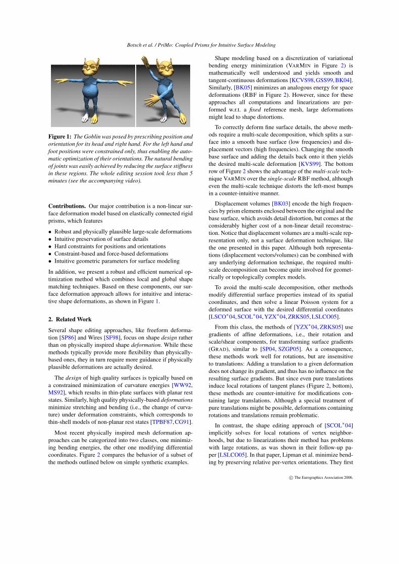
Figure 1: The Goblin was posed by prescribing position andorientation for its head and right hand. For the left hand andfoot positions were constrained only, thus enabling the auto-matic optimization of their orientations. The natural bendingof joints was easily achieved by reducing the surface stiffnessin these regions. The whole editing session took less than 5minutes (see the accompanying video).
Contributions. Our major contribution is a non-linear sur-face deformation model based on elastically connected rigidprisms, which features
• Robust and physically plausible large-scale deformations• Intuitive preservation of surface details• Hard constraints for positions and orientations• Constraint-based and force-based deformations• Intuitive geometric parameters for surface modeling
In addition, we present a robust and efficient numerical op-timization method which combines local and global shapematching techniques. Based on these components, our sur-face deformation approach allows for intuitive and interac-tive shape deformations, as shown in Figure 1.
2. Related Work
Several shape editing approaches, like freeform deforma-tion [SP86] and Wires [SF98], focus on shape design ratherthan on physically inspired shape deformation. While thesemethods typically provide more flexibility than physically-based ones, they in turn require more guidance if physicallyplausible deformations are actually desired.
The design of high quality surfaces is typically based ona constrained minimization of curvature energies [WW92,MS92], which results in thin-plate surfaces with planar reststates. Similarly, high quality physically-based deformationsminimize stretching and bending (i.e., the change of curva-ture) under deformation constraints, which corresponds tothin-shell models of non-planar rest states [TPBF87,CG91].
Most recent physically inspired mesh deformation ap-proaches can be categorized into two classes, one minimiz-ing bending energies, the other one modifying differentialcoordinates. Figure 2 compares the behavior of a subset ofthe methods outlined below on simple synthetic examples.
Shape modeling based on a discretization of variationalbending energy minimization (VARMIN in Figure 2) ismathematically well understood and yields smooth andtangent-continuous deformations [KCVS98, GSS99, BK04].Similarly, [BK05] minimizes an analogous energy for spacedeformations (RBF in Figure 2). However, since for theseapproaches all computations and linearizations are per-formed w.r.t. a fixed reference mesh, large deformationsmight lead to shape distortions.
To correctly deform fine surface details, the above meth-ods require a multi-scale decomposition, which splits a sur-face into a smooth base surface (low frequencies) and dis-placement vectors (high frequencies). Changing the smoothbase surface and adding the details back onto it then yieldsthe desired multi-scale deformation [KVS99]. The bottomrow of Figure 2 shows the advantage of the multi-scale tech-nique VARMIN over the single-scale RBF method, althougheven the multi-scale technique distorts the left-most bumpsin a counter-intuitive manner.
Displacement volumes [BK03] encode the high frequen-cies by prism elements enclosed between the original and thebase surface, which avoids detail distortion, but comes at theconsiderably higher cost of a non-linear detail reconstruc-tion. Notice that displacement volumes are a multi-scale rep-resentation only, not a surface deformation technique, likethe one presented in this paper. Although both representa-tions (displacement vectors/volumes) can be combined withany underlying deformation technique, the required multi-scale decomposition can become quite involved for geomet-rically or topologically complex models.
To avoid the multi-scale decomposition, other methodsmodify differential surface properties instead of its spatialcoordinates, and then solve a linear Poisson system for adeformed surface with the desired differential coordinates[LSCO∗04, SCOL∗04, YZX∗04, ZRKS05, LSLCO05].
From this class, the methods of [YZX∗04, ZRKS05] usegradients of affine deformations, i.e., their rotation andscale/shear components, for transforming surface gradients(GRAD), similar to [SP04, SZGP05]. As a consequence,these methods work well for rotations, but are insensitiveto translations: Adding a translation to a given deformationdoes not change its gradient, and thus has no influence on theresulting surface gradients. But since even pure translationsinduce local rotations of tangent planes (Figure 2, bottom),these methods are counter-intuitive for modifications con-taining large translations. Although a special treatment ofpure translations might be possible, deformations containingrotations and translations remain problematic.
In contrast, the shape editing approach of [SCOL∗04]implicitly solves for local rotations of vertex neighbor-hoods, but due to linearizations their method has problemswith large rotations, as was shown in their follow-up pa-per [LSLCO05]. In that paper, Lipman et al. minimize bend-ing by preserving relative per-vertex orientations. They first
c© The Eurographics Association 2006.
Botsch et al. / PriMo: Coupled Prisms for Intuitive Surface Modeling
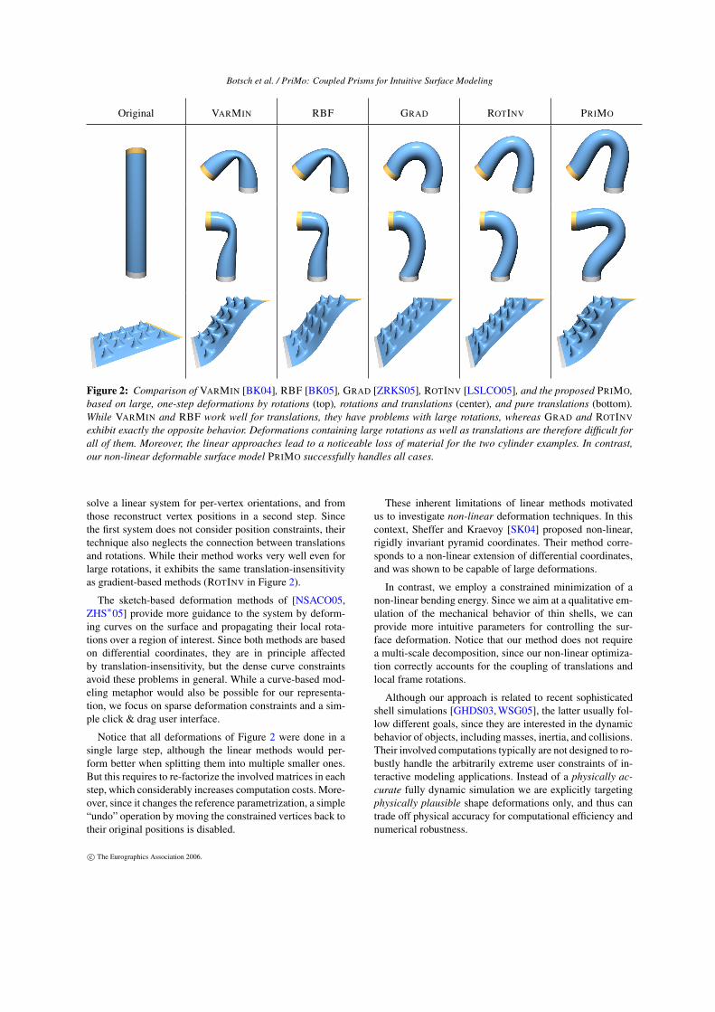
Original VARMIN RBF GRAD ROTINV PRIMO
Figure 2: Comparison of VARMIN [BK04], RBF [BK05], GRAD [ZRKS05], ROTINV [LSLCO05], and the proposed PRIMO,based on large, one-step deformations by rotations (top), rotations and translations (center), and pure translations (bottom).While VARMIN and RBF work well for translations, they have problems with large rotations, whereas GRAD and ROTINV
exhibit exactly the opposite behavior. Deformations containing large rotations as well as translations are therefore difficult forall of them. Moreover, the linear approaches lead to a noticeable loss of material for the two cylinder examples. In contrast,our non-linear deformable surface model PRIMO successfully handles all cases.
solve a linear system for per-vertex orientations, and fromthose reconstruct vertex positions in a second step. Sincethe first system does not consider position constraints, theirtechnique also neglects the connection between translationsand rotations. While their method works very well even forlarge rotations, it exhibits the same translation-insensitivityas gradient-based methods (ROTINV in Figure 2).
The sketch-based deformation methods of [NSACO05,ZHS∗05] provide more guidance to the system by deform-ing curves on the surface and propagating their local rota-tions over a region of interest. Since both methods are basedon differential coordinates, they are in principle affectedby translation-insensitivity, but the dense curve constraintsavoid these problems in general. While a curve-based mod-eling metaphor would also be possible for our representa-tion, we focus on sparse deformation constraints and a sim-ple click & drag user interface.
Notice that all deformations of Figure 2 were done in asingle large step, although the linear methods would per-form better when splitting them into multiple smaller ones.But this requires to re-factorize the involved matrices in eachstep, which considerably increases computation costs. More-over, since it changes the reference parametrization, a simple“undo” operation by moving the constrained vertices back totheir original positions is disabled.
These inherent limitations of linear methods motivatedus to investigate non-linear deformation techniques. In thiscontext, Sheffer and Kraevoy [SK04] proposed non-linear,rigidly invariant pyramid coordinates. Their method corre-sponds to a non-linear extension of differential coordinates,and was shown to be capable of large deformations.
In contrast, we employ a constrained minimization of anon-linear bending energy. Since we aim at a qualitative em-ulation of the mechanical behavior of thin shells, we canprovide more intuitive parameters for controlling the sur-face deformation. Notice that our method does not requirea multi-scale decomposition, since our non-linear optimiza-tion correctly accounts for the coupling of translations andlocal frame rotations.
Although our approach is related to recent sophisticatedshell simulations [GHDS03, WSG05], the latter usually fol-low different goals, since they are interested in the dynamicbehavior of objects, including masses, inertia, and collisions.Their involved computations typically are not designed to ro-bustly handle the arbitrarily extreme user constraints of in-teractive modeling applications. Instead of a physically ac-curate fully dynamic simulation we are explicitly targetingphysically plausible shape deformations only, and thus cantrade off physical accuracy for computational efficiency andnumerical robustness.
c© The Eurographics Association 2006.
Botsch et al. / PriMo: Coupled Prisms for Intuitive Surface Modeling
Initial State
Bending
Stretching
h
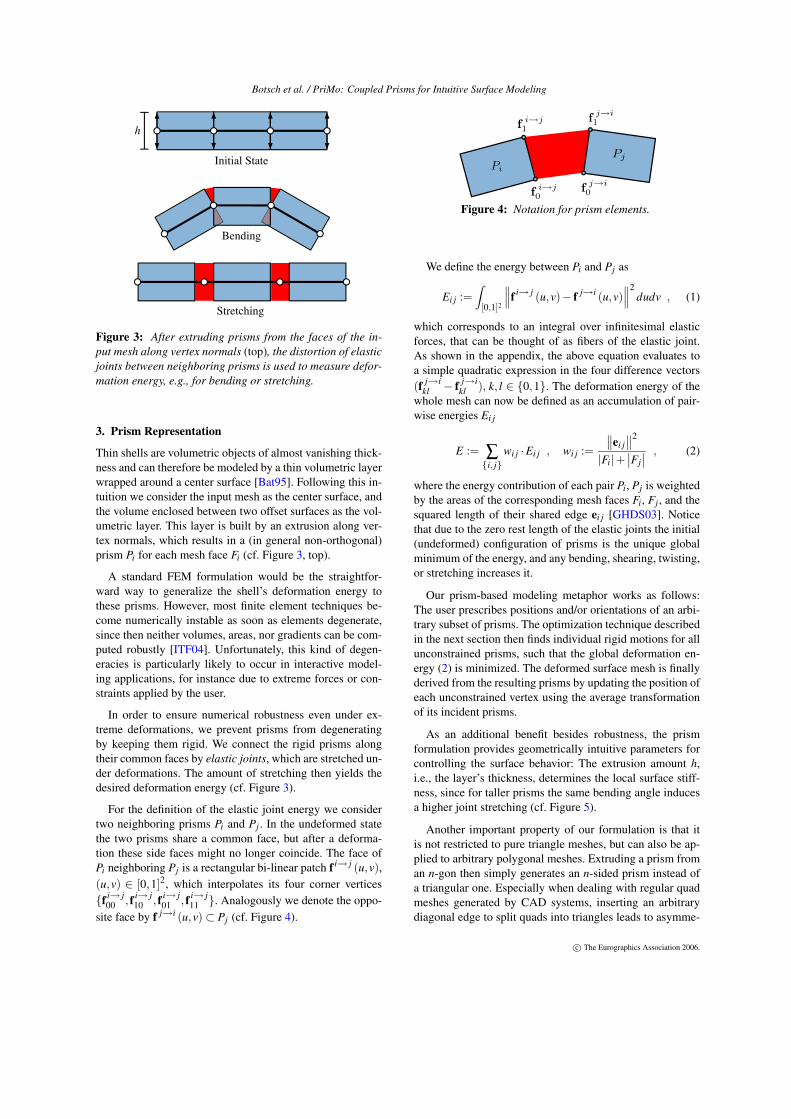
Figure 3: After extruding prisms from the faces of the in-put mesh along vertex normals (top), the distortion of elasticjoints between neighboring prisms is used to measure defor-mation energy, e.g., for bending or stretching.
3. Prism Representation
Thin shells are volumetric objects of almost vanishing thick-ness and can therefore be modeled by a thin volumetric layerwrapped around a center surface [Bat95]. Following this in-tuition we consider the input mesh as the center surface, andthe volume enclosed between two offset surfaces as the vol-umetric layer. This layer is built by an extrusion along ver-tex normals, which results in a (in general non-orthogonal)prism Pi for each mesh face Fi (cf. Figure 3, top).
A standard FEM formulation would be the straightfor-ward way to generalize the shell’s deformation energy tothese prisms. However, most finite element techniques be-come numerically instable as soon as elements degenerate,since then neither volumes, areas, nor gradients can be com-puted robustly [ITF04]. Unfortunately, this kind of degen-eracies is particularly likely to occur in interactive model-ing applications, for instance due to extreme forces or con-straints applied by the user.
In order to ensure numerical robustness even under ex-treme deformations, we prevent prisms from degeneratingby keeping them rigid. We connect the rigid prisms alongtheir common faces by elastic joints, which are stretched un-der deformations. The amount of stretching then yields thedesired deformation energy (cf. Figure 3).
For the definition of the elastic joint energy we considertwo neighboring prisms Pi and Pj. In the undeformed statethe two prisms share a common face, but after a deforma-tion these side faces might no longer coincide. The face ofPi neighboring Pj is a rectangular bi-linear patch f i→ j (u,v),(u,v) ∈ [0,1]2, which interpolates its four corner vertices{f i→ j
00 , f i→ j10 , f i→ j
01 , f i→ j11 }. Analogously we denote the oppo-
site face by f j→i (u,v)⊂ Pj (cf. Figure 4).
Pi
Pj
fi→j
0
fi→j
1
fj→i
1
fj→i
0
Figure 4: Notation for prism elements.
We define the energy between Pi and Pj as
Ei j :=Z
[0,1]2
f i→ j (u,v)− f j→i (u,v)
2dudv , (1)
which corresponds to an integral over infinitesimal elasticforces, that can be thought of as fibers of the elastic joint.As shown in the appendix, the above equation evaluates toa simple quadratic expression in the four difference vectors(f j→i
kl − f j→ikl ), k, l ∈ {0,1}. The deformation energy of the
whole mesh can now be defined as an accumulation of pair-wise energies Ei j
E := ∑{i, j}
wi j ·Ei j , wi j :=
ei j2
|Fi|+Fj
, (2)
where the energy contribution of each pair Pi, Pj is weightedby the areas of the corresponding mesh faces Fi, Fj, and thesquared length of their shared edge ei j [GHDS03]. Noticethat due to the zero rest length of the elastic joints the initial(undeformed) configuration of prisms is the unique globalminimum of the energy, and any bending, shearing, twisting,or stretching increases it.
Our prism-based modeling metaphor works as follows:The user prescribes positions and/or orientations of an arbi-trary subset of prisms. The optimization technique describedin the next section then finds individual rigid motions for allunconstrained prisms, such that the global deformation en-ergy (2) is minimized. The deformed surface mesh is finallyderived from the resulting prisms by updating the position ofeach unconstrained vertex using the average transformationof its incident prisms.
As an additional benefit besides robustness, the prismformulation provides geometrically intuitive parameters forcontrolling the surface behavior: The extrusion amount h,i.e., the layer’s thickness, determines the local surface stiff-ness, since for taller prisms the same bending angle inducesa higher joint stretching (cf. Figure 5).
Another important property of our formulation is that itis not restricted to pure triangle meshes, but can also be ap-plied to arbitrary polygonal meshes. Extruding a prism froman n-gon then simply generates an n-sided prism instead ofa triangular one. Especially when dealing with regular quadmeshes generated by CAD systems, inserting an arbitrarydiagonal edge to split quads into triangles leads to asymme-
c The Eurographics Association 2006.
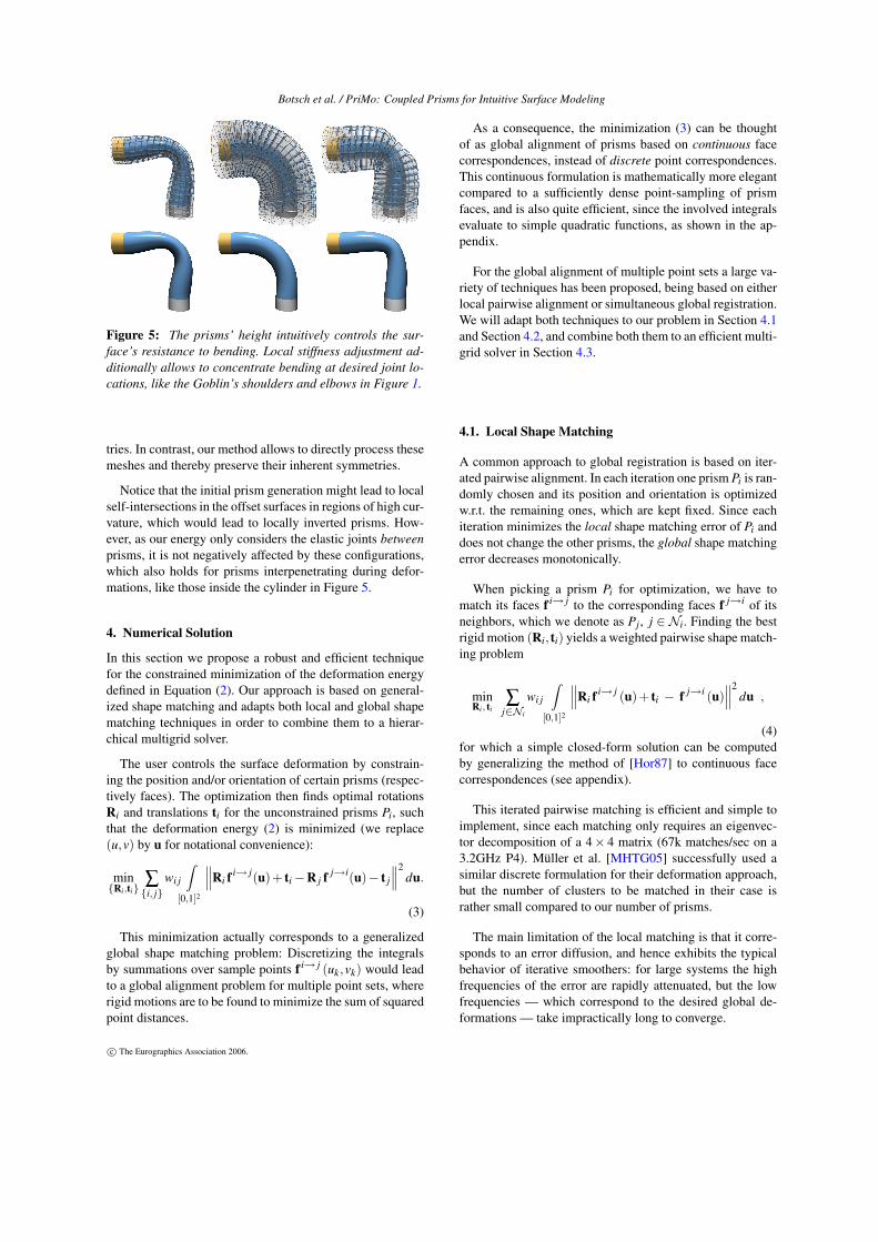
Botsch et al. / PriMo: Coupled Prisms for Intuitive Surface Modeling
Figure 5: The prisms’ height intuitively controls the sur-face’s resistance to bending. Local stiffness adjustment ad-ditionally allows to concentrate bending at desired joint lo-cations, like the Goblin’s shoulders and elbows in Figure 1.
tries. In contrast, our method allows to directly process thesemeshes and thereby preserve their inherent symmetries.
Notice that the initial prism generation might lead to localself-intersections in the offset surfaces in regions of high cur-vature, which would lead to locally inverted prisms. How-ever, as our energy only considers the elastic joints betweenprisms, it is not negatively affected by these configurations,which also holds for prisms interpenetrating during defor-mations, like those inside the cylinder in Figure 5.
4. Numerical Solution
In this section we propose a robust and efficient techniquefor the constrained minimization of the deformation energydefined in Equation (2). Our approach is based on general-ized shape matching and adapts both local and global shapematching techniques in order to combine them to a hierar-chical multigrid solver.
The user controls the surface deformation by constrain-ing the position and/or orientation of certain prisms (respec-tively faces). The optimization then finds optimal rotationsRi and translations ti for the unconstrained prisms Pi, suchthat the deformation energy (2) is minimized (we replace(u,v) by u for notational convenience):
min{Ri,ti}
∑{i, j}
wi j
Z[0,1]2
∥∥∥Ri f i→ j(u)+ ti−R j f j→i(u)− t j
∥∥∥2du.
(3)
This minimization actually corresponds to a generalizedglobal shape matching problem: Discretizing the integralsby summations over sample points f i→ j (uk,vk) would leadto a global alignment problem for multiple point sets, whererigid motions are to be found to minimize the sum of squaredpoint distances.
As a consequence, the minimization (3) can be thoughtof as global alignment of prisms based on continuous facecorrespondences, instead of discrete point correspondences.This continuous formulation is mathematically more elegantcompared to a sufficiently dense point-sampling of prismfaces, and is also quite efficient, since the involved integralsevaluate to simple quadratic functions, as shown in the ap-pendix.
For the global alignment of multiple point sets a large va-riety of techniques has been proposed, being based on eitherlocal pairwise alignment or simultaneous global registration.We will adapt both techniques to our problem in Section 4.1and Section 4.2, and combine both them to an efficient multi-grid solver in Section 4.3.
4.1. Local Shape Matching
A common approach to global registration is based on iter-ated pairwise alignment. In each iteration one prism Pi is ran-domly chosen and its position and orientation is optimizedw.r.t. the remaining ones, which are kept fixed. Since eachiteration minimizes the local shape matching error of Pi anddoes not change the other prisms, the global shape matchingerror decreases monotonically.
When picking a prism Pi for optimization, we have tomatch its faces f i→ j to the corresponding faces f j→i of itsneighbors, which we denote as Pj , j ∈ Ni. Finding the bestrigid motion (Ri, ti) yields a weighted pairwise shape match-ing problem
minRi, ti
∑j∈Ni
wi j
Z[0,1]2
∥∥∥Ri f i→ j (u)+ ti − f j→i (u)∥∥∥2
du ,
(4)for which a simple closed-form solution can be computedby generalizing the method of [Hor87] to continuous facecorrespondences (see appendix).
This iterated pairwise matching is efficient and simple toimplement, since each matching only requires an eigenvec-tor decomposition of a 4× 4 matrix (67k matches/sec on a3.2GHz P4). Müller et al. [MHTG05] successfully used asimilar discrete formulation for their deformation approach,but the number of clusters to be matched in their case israther small compared to our number of prisms.
The main limitation of the local matching is that it corre-sponds to an error diffusion, and hence exhibits the typicalbehavior of iterative smoothers: for large systems the highfrequencies of the error are rapidly attenuated, but the lowfrequencies — which correspond to the desired global de-formations — take impractically long to converge.
c© The Eurographics Association 2006.
Botsch et al. / PriMo: Coupled Prisms for Intuitive Surface Modeling
4.2. Global Shape Matching
Instead of iterated pairwise registrations, several techniquesfor the simultaneous registration of multiple point sets havebeen proposed, see [KLMV05] and the references therein.Most of these methods factorize dense matrices, whose di-mensions are proportional to the number of objects to bematched. While this is not critical when matching < 100 ob-jects, in our setting a large number of prisms would lead toprohibitively complex matrices.
In contrast, Pottmann et al. [PLH02] propose an iterativesimultaneous registration which involves solving sparse lin-ear systems only, and hence can be adapted to our problem.Their technique corresponds to a Newton-type minimizationof the registration error: In each iteration a linear system issolved for a descent direction, which corresponds to an affinemotion per prism. A projection of those onto the manifold ofrigid motions results in a rigid update for each prism. Thisprocess is iterated until convergence.
The descent direction of the Newton-type iteration re-quires first-order approximations Ai of rigid motions (Ri, ti),which can be formulated in terms of linear and angular ve-locities vi and ωi:
Ri (·)+ ti ≈ (·) + ωi× (·) + vi =: Ai (·) . (5)
Reformulating the energy minimization (3) in terms of thesefirst-order approximations yields
min{vi,ωi}
∑{i, j}
wi j
Z
[0,1]2
Ai
f i→ j (u)
−A j
f j→i (u)
2
du .
(6)As all integrals can again by evaluated analytically, (6) rep-resents a standard quadratic minimization in the linear andangular velocities, the optimal values for which can be foundby solving a sparse linear system [PLH02].
The resulting optimal velocities (vi,ωi) correspond to theNewton descent direction and represent first-order approxi-mations Ai. Since those are affine transformations, they haveto be projected back onto the manifold of rigid motions be-fore applying them to the prisms Pi. For this step, [PLH02]propose to choose (Ri, ti) as the helical motion associatedwith (vi,ωi). However, this method turned out to be re-stricted to very small update steps, which is sufficient forregistering pre-aligned point sets, but in our case leads toimpractically slow convergence for large deformations.
We therefore propose to project Ai by finding the “clos-est” rigid motion (Ri, ti), where we measure distances oftransformations by comparing their effects on the prism Pi.We find the closest rigid motion by minimizing
minRi, ti
Z
[0,1]2
Ri f i→ j (u)+ ti − Ai
f i→ j (u)
2
du , (7)
which yields another local shape matching problem, as de-picted in the following figure.
Pi
Ri P
i + ti
Ai(Pi)
This geometrically intuitive projection operator allows formuch larger update steps compared to the helical motionsof [PLH02], which reduces the number of required Newton-type iterations by a factor of about 50 in all our examples.Although our projection is computationally more involved,its costs are still small compared to solving (6). Hence, theoverall performance increases by roughly the same factor.
Finally, the Newton-like descent direction has to be scaledby a suitable step size λ. We thus derive the rigid motions(Ri, ti) by projecting scaled velocities (λvi, λωi) instead,where we simply start with λ = 1 and subsequently halveλ until the new rigid motions are found to decrease the en-ergy (3). Although more elaborate methods exist [PHYH04],this simple technique turned out to be sufficient.
The computational complexity of the non-linear optimiza-tion is dominated by factorizing and solving the linear sys-tem corresponding to the minimization of (6) in each iter-ation. Since the matrix is sparse (about 16 non-zeros/rowon average), symmetric, and positive definite, an efficientsparse Cholesky solver can be used [TCR03]. We can addi-tionally exploit that the non-zero structure of the matrix staysfixed throughout all iterations. This allows us to precomputethe symbolic part of the factorization [BBK05], which savesabout 40% of the total time per iteration.
Combining the matching-based projection (7) with thesymbolic pre-factorization reduces computation time by twoorders of magnitude compared to [PLH02]. However, the op-timization still achieves only 6500 prism updates per secondon a 3.2GHz P4, which is not sufficient for interactive defor-mations of complex meshes. Given these limitations, neitherthe local nor the global shape matching yields a practicallyuseful minimization technique by itself. But combining theirrespective strengths allows us to derive an efficient hierarchi-cal method, as we will show in the next section.
4.3. Hierarchical Shape Matching
To maximize computational efficiency, we perform theshape matching on a multigrid hierarchy. For multigridmethods on irregular triangle meshes the successivelycoarser levels are built by mesh decimation [AKS05]. How-ever, our framework does not require the hierarchy levelsto represent consistent triangulations, since prisms can begenerated from arbitrary polygons. This enables us to con-veniently build the hierarchies levels (typically about 4) bysuccessive clustering of neighboring faces and combiningtheir corresponding prisms by considering them as one sin-gle rigid group.
c The Eurographics Association 2006.
Botsch et al. / PriMo: Coupled Prisms for Intuitive Surface Modeling
A common practice for hierarchical multigrid solvers oflinear systems [AKS05] is to use a direct solver on a coarsehierarchy level to obtain a low frequency approximation ofthe solution, which then is successively refined on higherlevels using iterative techniques. Similarly, we start by ap-plying the global shape matching on the coarsest hierarchylevel in order to efficiently compute the low frequencies ofthe deformation. Since even for detailed surface meshes theshape deformations generally are smooth (low frequency)functions, this initial approximation typically is already veryclose to the exact solution. Since the local shape matchingcorresponds to an iterative error diffusion, we apply a fewiterations (typically 2) on each finer hierarchy level, whichrapidly smooths out the remaining high frequency errors.
Since we do not require consistent triangulations orsophisticated multigrid pre-conditioning, our hierarchicalsolver is considerably easier to implement compared to tra-ditional multigrid techniques. The efficient combination ofglobal and local shape matching yields a robust hierarchicalnon-linear optimization, which provides shape deformationsof moderately complex models at interactive rates. Even ourtwo most complex models, the 100k triangle Dragon of Fig-ure 8 and the 180k triangle Goblin of Figure 1, can be editedinteractively at one frame/sec (see the accompanying video).
4.4. Robustness
One of the main advantages of our method — and the maindifference to existing shell-based techniques — is that dur-ing a deformation the shape quality of prisms will not de-grade, since the individual prisms are kept rigid, which guar-antees numerical robustness even for extreme deformations.
Even the initial shape quality of the prisms — which de-pends on the input mesh — only has a minor influence onthe robustness of our method. The local and global shapematching techniques only fail for prisms that degenerate toa single line, which requires their corresponding triangles todegenerate to single points. However, the more likely casesof needle triangles (one extremely short edge) or caps trian-gles (one large angle) do not cause numerical problems, aslong as stable normals can be computed for the prism extru-sion. This allows us to process even meshes of low initialquality, which would be very likely to cause problems forclassical FEM simulations.
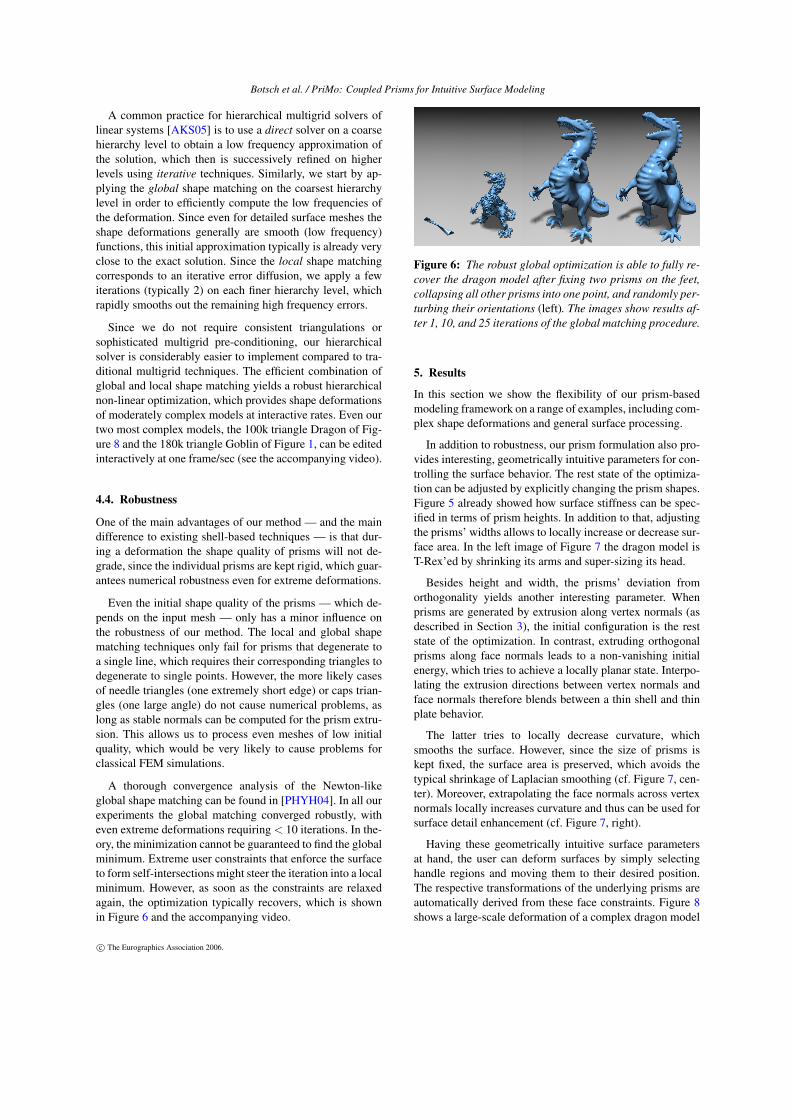
A thorough convergence analysis of the Newton-likeglobal shape matching can be found in [PHYH04]. In all ourexperiments the global matching converged robustly, witheven extreme deformations requiring < 10 iterations. In the-ory, the minimization cannot be guaranteed to find the globalminimum. Extreme user constraints that enforce the surfaceto form self-intersections might steer the iteration into a localminimum. However, as soon as the constraints are relaxedagain, the optimization typically recovers, which is shownin Figure 6 and the accompanying video.
Figure 6: The robust global optimization is able to fully re-cover the dragon model after fixing two prisms on the feet,collapsing all other prisms into one point, and randomly per-turbing their orientations (left). The images show results af-ter 1, 10, and 25 iterations of the global matching procedure.
5. Results
In this section we show the flexibility of our prism-basedmodeling framework on a range of examples, including com-plex shape deformations and general surface processing.
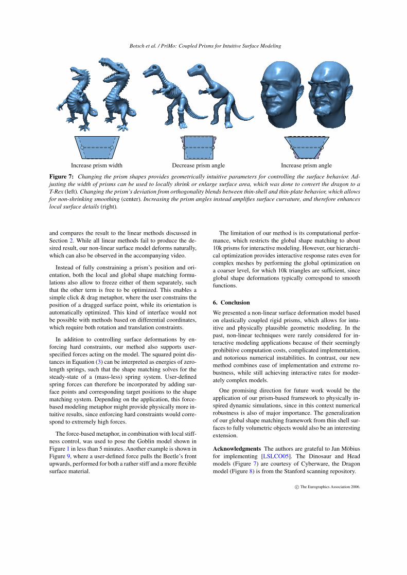
In addition to robustness, our prism formulation also pro-vides interesting, geometrically intuitive parameters for con-trolling the surface behavior. The rest state of the optimiza-tion can be adjusted by explicitly changing the prism shapes.Figure 5 already showed how surface stiffness can be spec-ified in terms of prism heights. In addition to that, adjustingthe prisms’ widths allows to locally increase or decrease sur-face area. In the left image of Figure 7 the dragon model isT-Rex’ed by shrinking its arms and super-sizing its head.
Besides height and width, the prisms’ deviation fromorthogonality yields another interesting parameter. Whenprisms are generated by extrusion along vertex normals (asdescribed in Section 3), the initial configuration is the reststate of the optimization. In contrast, extruding orthogonalprisms along face normals leads to a non-vanishing initialenergy, which tries to achieve a locally planar state. Interpo-lating the extrusion directions between vertex normals andface normals therefore blends between a thin shell and thinplate behavior.
The latter tries to locally decrease curvature, whichsmooths the surface. However, since the size of prisms iskept fixed, the surface area is preserved, which avoids thetypical shrinkage of Laplacian smoothing (cf. Figure 7, cen-ter). Moreover, extrapolating the face normals across vertexnormals locally increases curvature and thus can be used forsurface detail enhancement (cf. Figure 7, right).
Having these geometrically intuitive surface parametersat hand, the user can deform surfaces by simply selectinghandle regions and moving them to their desired position.The respective transformations of the underlying prisms areautomatically derived from these face constraints. Figure 8shows a large-scale deformation of a complex dragon model
c© The Eurographics Association 2006.
Botsch et al. / PriMo: Coupled Prisms for Intuitive Surface Modeling
Increase prism width Decrease prism angle Increase prism angle
Figure 7: Changing the prism shapes provides geometrically intuitive parameters for controlling the surface behavior. Ad-justing the width of prisms can be used to locally shrink or enlarge surface area, which was done to convert the dragon to aT-Rex (left). Changing the prism’s deviation from orthogonality blends between thin-shell and thin-plate behavior, which allowsfor non-shrinking smoothing (center). Increasing the prism angles instead amplifies surface curvature, and therefore enhanceslocal surface details (right).
and compares the result to the linear methods discussed inSection 2. While all linear methods fail to produce the de-sired result, our non-linear surface model deforms naturally,which can also be observed in the accompanying video.
Instead of fully constraining a prism’s position and ori-entation, both the local and global shape matching formu-lations also allow to freeze either of them separately, suchthat the other term is free to be optimized. This enables asimple click & drag metaphor, where the user constrains theposition of a dragged surface point, while its orientation isautomatically optimized. This kind of interface would notbe possible with methods based on differential coordinates,which require both rotation and translation constraints.
In addition to controlling surface deformations by en-forcing hard constraints, our method also supports user-specified forces acting on the model. The squared point dis-tances in Equation (3) can be interpreted as energies of zero-length springs, such that the shape matching solves for thesteady-state of a (mass-less) spring system. User-definedspring forces can therefore be incorporated by adding sur-face points and corresponding target positions to the shapematching system. Depending on the application, this force-based modeling metaphor might provide physically more in-tuitive results, since enforcing hard constraints would corre-spond to extremely high forces.
The force-based metaphor, in combination with local stiff-ness control, was used to pose the Goblin model shown inFigure 1 in less than 5 minutes. Another example is shown inFigure 9, where a user-defined force pulls the Beetle’s frontupwards, performed for both a rather stiff and a more flexiblesurface material.
The limitation of our method is its computational perfor-mance, which restricts the global shape matching to about10k prisms for interactive modeling. However, our hierarchi-cal optimization provides interactive response rates even forcomplex meshes by performing the global optimization ona coarser level, for which 10k triangles are sufficient, sinceglobal shape deformations typically correspond to smoothfunctions.
6. Conclusion
We presented a non-linear surface deformation model basedon elastically coupled rigid prisms, which allows for intu-itive and physically plausible geometric modeling. In thepast, non-linear techniques were rarely considered for in-teractive modeling applications because of their seeminglyprohibitive computation costs, complicated implementation,and notorious numerical instabilities. In contrast, our newmethod combines ease of implementation and extreme ro-bustness, while still achieving interactive rates for moder-ately complex models.
One promising direction for future work would be theapplication of our prism-based framework to physically in-spired dynamic simulations, since in this context numericalrobustness is also of major importance. The generalizationof our global shape matching framework from thin shell sur-faces to fully volumetric objects would also be an interestingextension.
Acknowledgments The authors are grateful to Jan Möbiusfor implementing [LSLCO05]. The Dinosaur and Headmodels (Figure 7) are courtesy of Cyberware, the Dragonmodel (Figure 8) is from the Stanford scanning repository.
c The Eurographics Association 2006.
Botsch et al. / PriMo: Coupled Prisms for Intuitive Surface Modeling
Original VARMIN RBF GRAD ROTINV PRIMO
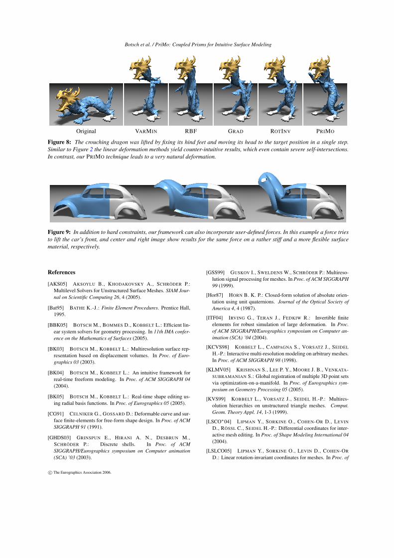
Figure 8: The crouching dragon was lifted by fixing its hind feet and moving its head to the target position in a single step.Similar to Figure 2 the linear deformation methods yield counter-intuitive results, which even contain severe self-intersections.In contrast, our PRIMO technique leads to a very natural deformation.
Figure 9: In addition to hard constraints, our framework can also incorporate user-defined forces. In this example a force triesto lift the car’s front, and center and right image show results for the same force on a rather stiff and a more flexible surfacematerial, respectively.
References
[AKS05] AKSOYLU B., KHODAKOVSKY A., SCHRÖDER P.:Multilevel Solvers for Unstructured Surface Meshes. SIAM Jour-nal on Scientific Computing 26, 4 (2005).
[Bat95] BATHE K.-J.: Finite Element Procedures. Prentice Hall,1995.
[BBK05] BOTSCH M., BOMMES D., KOBBELT L.: Efficient lin-ear system solvers for geometry processing. In 11th IMA confer-ence on the Mathematics of Surfaces (2005).
[BK03] BOTSCH M., KOBBELT L.: Multiresolution surface rep-resentation based on displacement volumes. In Proc. of Euro-graphics 03 (2003).
[BK04] BOTSCH M., KOBBELT L.: An intuitive framework forreal-time freeform modeling. In Proc. of ACM SIGGRAPH 04(2004).
[BK05] BOTSCH M., KOBBELT L.: Real-time shape editing us-ing radial basis functions. In Proc. of Eurographics 05 (2005).
[CG91] CELNIKER G., GOSSARD D.: Deformable curve and sur-face finite-elements for free-form shape design. In Proc. of ACMSIGGRAPH 91 (1991).
[GHDS03] GRINSPUN E., HIRANI A. N., DESBRUN M.,SCHRÖDER P.: Discrete shells. In Proc. of ACMSIGGRAPH/Eurographics symposium on Computer animation(SCA) ’03 (2003).
[GSS99] GUSKOV I., SWELDENS W., SCHRÖDER P.: Multireso-lution signal processing for meshes. In Proc. of ACM SIGGRAPH99 (1999).
[Hor87] HORN B. K. P.: Closed-form solution of absolute orien-tation using unit quaternions. Journal of the Optical Society ofAmerica 4, 4 (1987).
[ITF04] IRVING G., TERAN J., FEDKIW R.: Invertible finiteelements for robust simulation of large deformation. In Proc.of ACM SIGGRAPH/Eurographics symposium on Computer an-imation (SCA) ’04 (2004).
[KCVS98] KOBBELT L., CAMPAGNA S., VORSATZ J., SEIDEL
H.-P.: Interactive multi-resolution modeling on arbitrary meshes.In Proc. of ACM SIGGRAPH 98 (1998).
[KLMV05] KRISHNAN S., LEE P. Y., MOORE J. B., VENKATA-SUBRAMANIAN S.: Global registration of multiple 3D point setsvia optimization-on-a-manifold. In Proc. of Eurographics sym-posium on Geometry Processing 05 (2005).
[KVS99] KOBBELT L., VORSATZ J., SEIDEL H.-P.: Multires-olution hierarchies on unstructured triangle meshes. Comput.Geom. Theory Appl. 14, 1-3 (1999).
[LSCO∗04] LIPMAN Y., SORKINE O., COHEN-OR D., LEVIN
D., RÖSSL C., SEIDEL H.-P.: Differential coordinates for inter-active mesh editing. In Proc. of Shape Modeling International 04(2004).
[LSLCO05] LIPMAN Y., SORKINE O., LEVIN D., COHEN-OR
D.: Linear rotation-invariant coordinates for meshes. In Proc. of
c© The Eurographics Association 2006.
Botsch et al. / PriMo: Coupled Prisms for Intuitive Surface Modeling
ACM SIGGRAPH 05 (2005).
[MHTG05] MÜLLER M., HEIDELBERGER B., TESCHNER M.,GROSS M.: Meshless deformations based on shape matching. InProc. of ACM SIGGRAPH 05 (2005).
[MS92] MORETON H. P., SÉQUIN C. H.: Functional optimiza-tion for fair surface design. In Proc. of ACM SIGGRAPH 92(1992).
[NSACO05] NEALEN A., SORKINE O., ALEXA M., COHEN-OR D.: A sketch-based interface for detail-preserving mesh edit-ing. In Proc. of ACM SIGGRAPH 05 (2005).
[PHYH04] POTTMANN H., HUANG Q.-X., YANG Y.-L., HU S.-M.: Geometry and convergence analysis of algorithms for reg-istration of 3D shapes. Tech. Rep. 117, Vienne University ofTechnology, 2004.
[PLH02] POTTMANN H., LEOPOLDSEDER S., HOFER M.: Si-multaneous registration of multiple views of a 3D object.Archives of the Photogrammetry, Remote Sensing and Spatial In-formation Sciences 34, 3A (2002).
[SCOL∗04] SORKINE O., COHEN-OR D., LIPMAN Y., ALEXA
M., RÖSSL C., SEIDEL H.-P.: Laplacian surface editing. InProc. of Eurographics symposium on Geometry Processing 04(2004).
[SF98] SINGH K., FIUME E.: Wires: A geometric deformationtechnique. In Proc. of ACM SIGGRAPH 98 (1998).
[SK04] SHEFFER A., KRAEVOY V.: Pyramid coordinates formorphing and deformation. In Proc. of Symp. on 3D Data Pro-cessing, Visualization and Transmission (3DPVT) ’04 (2004).
[SP86] SEDERBERG T. W., PARRY S. R.: Free-form deforma-tion of solid geometric models. In Proc. of ACM SIGGRAPH 86(1986).
[SP04] SUMNER R. W., POPOVIC J.: Deformation transfer fortriangle meshes. In Proc. of ACM SIGGRAPH 04 (2004).
[SZGP05] SUMNER R. W., ZWICKER M., GOTSMAN C.,POPOVIC J.: Mesh-based inverse kinematics. In Proc. of ACMSIGGRAPH 05 (2005).
[TCR03] TOLEDO S., CHEN D., ROTKIN V.: Taucs: A library ofsparse linear solvers. http://www.tau.ac.il/∼stoledo/taucs, 2003.
[TPBF87] TERZOPOULOS D., PLATT J., BARR A., FLEISCHER
K.: Elastically deformable models. In Proc. of ACM SIGGRAPH87 (1987).
[WSG05] WICKE M., STEINEMANN D., GROSS M.: Efficientanimation of point-sampled thin shells. In Proc. of Eurographics05 (2005).
[WW92] WELCH W., WITKIN A.: Variational surface modeling.In Proc. of ACM SIGGRAPH 92 (1992).
[YZX∗04] YU Y., ZHOU K., XU D., SHI X., BAO H., GUO B.,SHUM H.-Y.: Mesh editing with Poisson-based gradient fieldmanipulation. In Proc. of ACM SIGGRAPH 04 (2004).
[ZHS∗05] ZHOU K., HUANG J., SNYDER J., LIU X., BAO H.,GUO B., SHUM H.-Y.: Large mesh deformation using the volu-metric graph Laplacian. In Proc. of ACM SIGGRAPH 05 (2005).
[ZRKS05] ZAYER R., RÖSSL C., KARNI Z., SEIDEL H.-P.:Harmonic guidance for surface deformation. In Proc. of Euro-graphics 05 (2005).
Appendix A: Continuous Face-Based Shape Matching
We show how to extend the local and global shape matching ap-proaches of [Hor87] and [PLH02] from discrete point correspon-dences to continuous face correspondences.
Suppose we are given two functions a (u) and b (u) definedby bi-linear interpolation of four values {a00,a10,a01,a11} and{b00,b10,b01,b11}, respectively. Then their L2 inner product sim-plifies to a weighted sum of 16 combinations of corner values:Z
[0,1]2
a (u) ·b (u)du =19
1
∑i, j,k,l=0
ai j ·bkl ·2(−|i−k|−| j−l|)
=: 〈a, b〉2 .
Using this, the continuous pairwise energy of Equation (1) evaluatesto
Ei j =⟨f i→ j − f j→i, f i→ j − f j→i⟩
2 .
In order to generalize the local shape matching of [Hor87], wefirst compute the weighted centroids ci and c∗ of the two face setsto be aligned, which leads to
ci
c∗
}=
1
∑ j∈Niwi j
∑j∈Ni
wi j
4
1
∑k,l=0
{f i→ jk,l
f j→ik,l
.
To derive the optimal rotation Ri according to [Hor87], we build thematrix N =
Sxx + Syy + Szz Syz −Szy Szx −Sxz Sxy −Syx
Syz −Szy Sxx −Syy −Szz Sxy + Syx Szx + Sxz
Szx −Sxz Sxy + Syx −Sxx + Syy −Szz Syz + Szy
Sxy −Syx Szx + Sxz Syz + Szy −Sxx −Syy + Szz
from the component-wise L2 inner products
Sxx = ∑j∈Ni
wi j
⟨(f i→ j − ci)
x ,(f j→i − c∗
)x
⟩2
,
Sxy = ∑j∈Ni
wi j
⟨(f i→ j − ci)
x ,(f j→i − c∗
)y
⟩2
,
and analogously for the other components. The eigenvector corre-sponding to the largest eigenvalue of N gives the optimal rotationRi when interpreted as a unit quaternion. The optimal translationfinally is ti = c∗−Ri ci.
For the generalization of the global shape matching approachof [PLH02] we have to adjust the linear system correspondingto the minimization of Equation (6). Assume two correspondingpoints p i→ j and p j→i sampled from neighboring faces f i→ j (u)and f j→i (u). Their contribution to the global energy is
wi j∥∥(
p i→ j + ωi ×p i→ j + vi)−
(p j→i + ω j ×p j→i + v j
)∥∥2,
which gives four 6× 6 matrix blocks. From those the global blockstructure of the matrix and the numeric values are easily derived.The continuous formulation then only requires to replace the in-volved products of the form (p i→ j)x ·(p j→i)y by the inner products⟨(
f i→ j)
x ,(f j→i
)y
⟩2
in the respective matrix entries.
c© The Eurographics Association 2006.