Embed Size (px)
Citation preview
HBS Series
Hybrid Servo Drive
Datasheet
Version HBS-2014-01
http://www.PrimoPal.com

HBS series Hybrid Servo Drives
PrimoPal Motor Co., Ltd. No.188, Zhangyang Road, Shanghai 200120, China Tel: +86 21 5018 7836 Fax: +86 21 5017 9351 Page 1 of 37 Website: http://www.primopal.com
Description
PrimoPal’s HBS series Hybrid Servo Drive offers an alternative for applications requiring high performance and
high reliability when the servo was the only choice, while it remains cost-effective. The system includes a stepper
motor combined with a fully digital, high performance drive and an internal encoder which is used to close the
position, velocity and current loops in real time, just like servo systems. They are featured with closed position
loop, offering huge torque, excellent acceleration & quick response, no torque reservation, high standstill stiffness,
extra low noise & heating, smooth motor movement, no hunting, no overshooting for almost zero settling time,
and no tuning for almost all applications.
Applications
PrimoPal’s HBS series Hybrid Servo Drives are suitable for both upgrading conventional stepper systems, and
replacing brushless servo systems which have closed loop and high torque requirements. These hybrid servo
drives and matching closed-loop stepper motors have been successfully implemented by many OEM clients in
applications such as CNC routers, plasma, milling machines, engravers, packaging machines, printing equipment,
and so on.
Part Number
PrimoPal’s Hybrid Servo Drives Summary
Model Phase Output Current
Operating Voltage
Driving Motors
Configuration Control
Type
A AC DC NEMA
HBS507 3 0.5-8.0 N/A 20-50 23-24 DIP Switch / RS232 Step & Dir
HBS806 2 0.5-8.2 N/A 24-80 23-34 DIP Switch / RS232 Step & Dir
HBS806AC 2 0.5-8.0 20-70 30-100 34 DIP Switch / RS232 Step & Dir
HBS1108AC 2 0.5-8.0 90-130 127-184 34-42 HMI / RS232 Step & Dir
HBS2206AC 2 0.5-6.0 150-230 212-325 34-42 HMI / RS232 Step & Dir
Max. Output Current 06: 6.0A 08: 8.0A ……
HBS
Max. Input Voltage 5: 50V 8: 80V ……
PrimoPal Hybrid Servo Drive
Serial Number (A-Z)

Datasheet of Hybrid Servo Drive HBS507
PrimoPal Motor Co., Ltd. No.188, Zhangyang Road, Shanghai 200120, China Tel: +86 21 5018 7836 Fax: +86 21 5017 9351 Page 2 of 37 Website: http://www.primopal.com
HBS507 Hybrid Servo Drive
20-50VDC, 8.0A Peak, Closed-loop, No Tuning
Closed-loop, eliminates loss of synchronization
Broader operating range – higher torque and higher speed
Reduced motor heating and more efficient
Smooth motion and super-low motor noise
Do not need a high torque margin
No Tuning and always stable
Quick response, no delay and almost no settle time
High torque at starting and low speed, high stiffness at standstill
Offer servo-like performance at a much lower cost
Specifications
Electrical Specifications
Parameter Min Typical Max Unit
Input Voltage 20 36 50 VDC
Output Current 0 - 8.0(Peak) A
Pulse Input Frequency 0 - 200 kHz
Logic Signal Current 7 10 16 mA
Isolation Resistance 500 - - MΩ
Operating Environment
Cooling Natural Cooling or Forced cooling
Operating Environment
Environment Avoid dust, oil fog and corrosive gases
Ambient Temperature 0℃ - 50℃ (32℉ - 122℉)
Humidity 40%RH - 90%RH
Operating Temperature (Heat sink) 70℃ (158℉) Max
Vibration 5.9m/s2 Max
Storage Temperature -20℃ - 65℃ (-4℉ - 149℉)
Weight 280g (10.0oz)
Datasheet of Hybrid Servo Drive HBS507
PrimoPal Motor Co., Ltd. No.188, Zhangyang Road, Shanghai 200120, China Tel: +86 21 5018 7836 Fax: +86 21 5017 9351 Page 3 of 37 Website: http://www.primopal.com
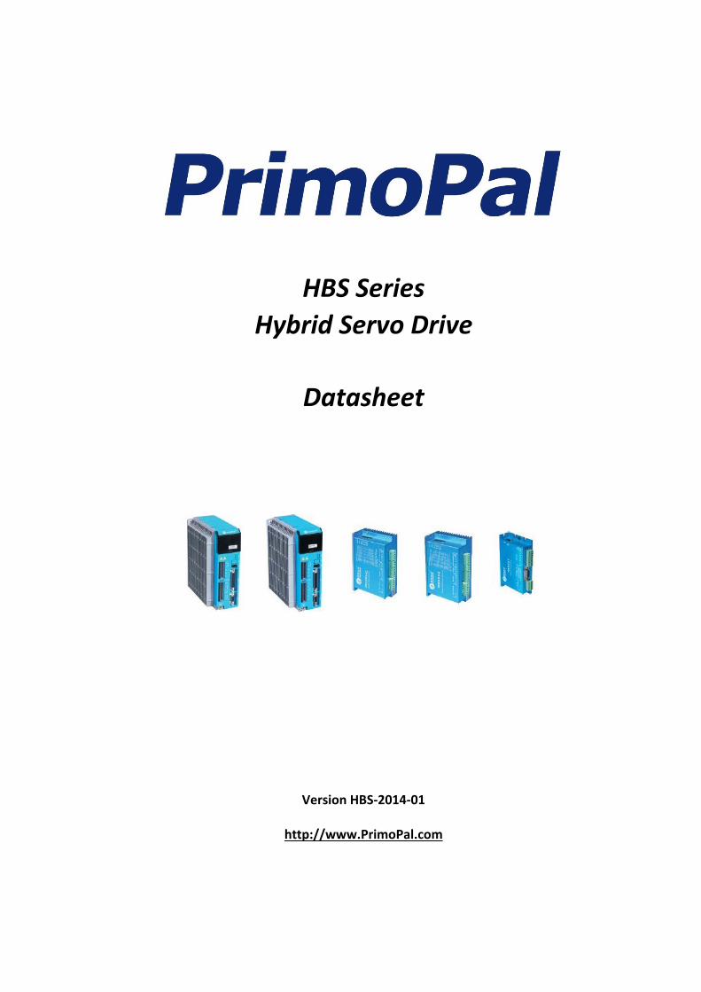
Mechanical Specifications
Protection Indications
Priority Time(s) of
Blink Sequence wave of RED LED Description
1st 1
Over-current protection
2nd 2
Over-voltage protection
3rd 7
Position Following Error
0.2S0.3S
5S
0 . 2 S 0 . 3 S 5 S
0 . 2 S 5 S

Datasheet of Hybrid Servo Drive HBS507
PrimoPal Motor Co., Ltd. No.188, Zhangyang Road, Shanghai 200120, China Tel: +86 21 5018 7836 Fax: +86 21 5017 9351 Page 4 of 37 Website: http://www.primopal.com
Connectors and Pin Assignment
The HBS507 has three connectors, connector for control signals connections, connector for encoder feedback and connector for power and motor connections.
Control Signal Connector - Screw Terminal
Pin Pin
Function I/O Description
1 PUL+ I
Pulse signal: In single pulse (pulse/direction) mode, this input represents pulse signal, each rising or falling edge active (software configurable, see the software operational manual for more details); In double pulse mode (software configurable), this input represents clockwise (CW) pulse, active both at high level and low level. 4-5V when PUL-HIGH, 0-0.5V when PUL-LOW. For reliable response, pulse width should be longer than 2.5μs. Series connect resistors for current-limiting when +12V or +24V used. The same as DIR and ENA signals.
2 PUL- I
3 DIR+ I Direction Signal: In single-pulse mode, this signal has low/high voltage levels, representing two directions of motor rotation. In double-pulse mode (software configurable), this signal is counter-clock (CCW) pulse, active both at high level and low level. For reliable motion response, DIR signal should be ahead of PUL signal by 5μs at least. 4-5V when DIR-HIGH, 0-0.5V when DIR-LOW. Toggle DIP switch SW1 to reverse motion direction.
4 DIR- I
5 ENA+ I Enable Signal: This signal is used for enabling/disabling the driver. In default, high level (NPN control signal) for enabling the driver and low level for disabling the driver. Usually left UNCONNECTED (ENABLED). Please note that PNP and Differential control signals are on the contrary, namely low level for enabling. The active level of ENA signal is software configurable.
6 ENA- I
7 ALM+ O
Alarm Signal: OC output signal, active when one of the following protection is activated: over-voltage, over current, short circuit and position following error. This port can sink or source 20mA current at 24V. In default, the resistance between ALM+ and ALM- is low impedance in normal operation and become high when the HBS57 goes into error. The active level of alarm signal is software configurable. See the software operational manual for more details.
8 ALM- O
Encoder Feedback Connector – HDD15 Female
Pin Name I/O Description
1 EA+ I Encoder channel A+ input
2 EB+ I Encoder channel B+ input
3 EGD GND Signal ground
4 NC I Not Connected, Reserved for future use.
5 NC I Not Connected, Reserved for future use.
6 FG - Ground terminal for shielded
7 NC I Not Connected, Reserved for future use.
8 NC I Not Connected, Reserved for future use.
9 NC I Not Connected, Reserved for future use.
10 NC - Not Connected
11 EA- I Encoder channel A- input
12 EB- I Encoder channel B- input

Datasheet of Hybrid Servo Drive HBS507
PrimoPal Motor Co., Ltd. No.188, Zhangyang Road, Shanghai 200120, China Tel: +86 21 5018 7836 Fax: +86 21 5017 9351 Page 5 of 37 Website: http://www.primopal.com
Connectors and Pin Assignment (Continued)
Encoder Feedback Connector – HDD15 Female
Pin Name I/O Description
13 VCC O +5V @100 mA max.
14 NC - Not Connected
15 NC - Not Connected
Power and Motor Connector- Screw Terminal
Pin Name I/O Description
1 U O Motor Phase U
2 V O Motor Phase V
3 W O Motor Phase W
4 +VDC I Power Supply Input (Positive) 20-45VDC recommended, leaving rooms for voltage fluctuation and back-EMF.
5 GND GND Power Ground (Negative)
RS232 Communication Port
It is used to configure the peak current, microstep, active level, current loop parameters and anti-resonance parameters.
RS232 Communication Port
Pin Name I/O Description
1 NC - Not connected.
2 +5V O +5V power output.
3 TxD O RS232 transmit.
4 GND GND Ground.
5 RxD I RS232 receive.
6 NC - Not connected.
DIP Switch - Motor SEL
The SW1 can be used to change the motor direction. The SW2 is reserved for future use.
Current Control
The motor current will be adjusted automatically regarding to the load or the stator-rotor relationship. However, the user can also configure the current in the tuning software. The configurable parameters include close-loop current, holding current, encoder resolution, micro step and etc.

Datasheet of Hybrid Servo Drive HBS507
PrimoPal Motor Co., Ltd. No.188, Zhangyang Road, Shanghai 200120, China Tel: +86 21 5018 7836 Fax: +86 21 5017 9351 Page 6 of 37 Website: http://www.primopal.com
Typical Connections
Connections to controller of sinking output
Connections to controller of sourcing output
Drive HBS507
GND
PUL+ 1
DIR+ 3
PUL-
DIR-
2
4
ALM+
U
V
W
+Vdc
Encoder Signal
Connector
7
1
2
3
4
5
ENA+ 5
ENA- 6
8ALM-
Encoder
Extension Cable
Power &
Motor Connector
VCC
Step
Direction
Enable
Alarm
Controller
5V
R
R
R
R=0 if VCC=5V;
R=1K(Power>0.125W) if VCC=12V;
R=2K(Power>0.125W) if VCC=24V;
R must be connected to control signal terminal.
Control Signal
Connector
20-45VDC recommended,
leaving rooms for voltage fluctuation
and back EMF of motor
Drive HBS507
GND
ALM+
U
V
W
+Vdc
Encoder Signal
Connector
7
1
2
3
4
58ALM-
Encoder
Extension Cable
Power &
Motor Connector
Alarm
Controller
5V
R=0 if VCC=5V;
R=1K(Power>0.125W) if VCC=12V;
R=2K(Power>0.125W) if VCC=24V;
R must be connected to control signal terminal.
Control Signal
Connector
PUL+ 1
DIR+ 3
PUL-
DIR-
2
4
ENA+ 5
ENA- 6
Step
Direction
Enable
VCC
VCC
VCC
R
R
R
20-45VDC recommended,
leaving rooms for voltage fluctuation
and back EMF of motor
Datasheet of Hybrid Servo Drive HBS507
PrimoPal Motor Co., Ltd. No.188, Zhangyang Road, Shanghai 200120, China Tel: +86 21 5018 7836 Fax: +86 21 5017 9351 Page 7 of 37 Website: http://www.primopal.com
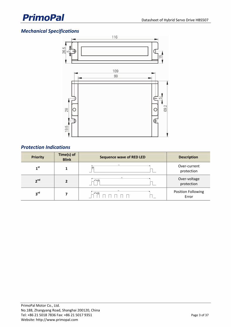
Typical Connections (Continued)
Connections to controller of differential output
Drive HBS507
GND
ALM+
U
V
W
+Vdc
Encoder Signal
Connector
7
1
2
3
4
58ALM-
Encoder
Extension Cable
Power &
Motor Connector
20-45VDC recommended,
leaving rooms for voltage fluctuation
and back EMF of motor
Alarm
Controller
5V
Control Signal
Connector
PUL+ 1
DIR+ 3
PUL-
DIR-
2
4
ENA+ 5
ENA- 6
5V
Step
Direction
Enable

Datasheet of Hybrid Servo Drive HBS806
PrimoPal Motor Co., Ltd. No.188, Zhangyang Road, Shanghai 200120, China Tel: +86 21 5018 7836 Fax: +86 21 5017 9351 Page 8 of 37 Website: http://www.primopal.com
HBS806 Hybrid Servo Drive
30-80VDC, 8.2A Peak, Closed-loop, No Tuning
Closed-loop, eliminates loss of synchronization
Broader operating range – higher torque and higher speed
Reduced motor heating and more efficient
Smooth motion and super-low motor noise
Do not need a high torque margin
No Tuning and always stable
Quick response, no delay and almost no settle time
High torque at starting and low speed, high stiffness at standstill
Offer servo-like performance at a much lower cost
Specifications
Electrical Specifications
Parameter Min Typical Max Unit
Input Voltage 30 48 80 VDC
Output Current 0 - 8.2(Peak) A
Pulse Input Frequency 0 - 200 kHz
Logic Signal Current 7 10 16 mA
Isolation Resistance 500 - - MΩ
Operating Environment
Cooling Natural Cooling or Forced cooling
Operating Environment
Environment Avoid dust, oil fog and corrosive gases
Ambient Temperature 0℃ - 50℃ (32℉ - 122℉)
Humidity 40%RH - 90%RH
Operating Temperature (Heat sink) 70℃ (158℉) Max
Vibration 5.9m/s2 Max
Storage Temperature -20℃ - 65℃ (-4℉ - 149℉)
Weight 580g (20.5oz)

Datasheet of Hybrid Servo Drive HBS806
PrimoPal Motor Co., Ltd. No.188, Zhangyang Road, Shanghai 200120, China Tel: +86 21 5018 7836 Fax: +86 21 5017 9351 Page 9 of 37 Website: http://www.primopal.com
Mechanical Specifications
Protection Indications
Priority Time(s) of
Blink Sequence wave of RED LED Description
1st 1
Over-current protection
2nd 2
Over-voltage protection
3rd 7
Position Following Error 0.2S0.3S
5S
0 . 2 S 0 . 3 S 5 S
0 . 2 S 5 S

Datasheet of Hybrid Servo Drive HBS806
PrimoPal Motor Co., Ltd. No.188, Zhangyang Road, Shanghai 200120, China Tel: +86 21 5018 7836 Fax: +86 21 5017 9351 Page 10 of 37 Website: http://www.primopal.com
Connectors and Pin Assignment
The HBS806 has three connectors, connector for control signals connections, connector for encoder feedback and connector for power and motor connections.
Control Signal Connector - Screw Terminal
Pin Pin
Function I/O Description
1 PUL+ I
Pulse signal: In single pulse (pulse/direction) mode, this input represents pulse signal, each rising or falling edge active (software configurable, see the software operational manual for more details); In double pulse mode (software configurable), this input represents clockwise (CW) pulse, active both at high level and low level. 4.5-24V when PUL-HIGH, 0-0.5V when PUL-LOW. For reliable response, pulse width should be longer than 2.5μs.
2 PUL- I
3 DIR+ I
Direction Signal: In single-pulse mode, this signal has low/high voltage levels, representing two directions of motor rotation. In double-pulse mode (software configurable), this signal is counter-clock (CCW) pulse, active both at high level and low level. For reliable motion response, DIR signal should be ahead of PUL signal by 5μs at least. 4.5-24V when DIR-HIGH, 0-0.5V when DIR-LOW. Please note that rotation direction is also related to motor-driver-encoder wiring match. Exchanging both the connection of two wires for a coil and an encoder channel to the driver he connection will reverse motion direction. Or you can toggle the SW5 to reverse the motion direction.
4 DIR- I
5 ENA+ I Enable signal: This signal is used for enabling/disabling the driver. In default, high level (NPN control signal) for enabling the driver and low level for disabling the driver. Usually left UNCONNECTED (ENABLED). Please note that PNP and Differential control signals are on the contrary, namely Low level for enabling. The active level of ENA signal is software configurable.
6 ENA- I
7 Pend+ O In-position Signal: OC output signal, active when the difference between the actual position and the command position is zero. This port can sink or source 20mA current at 24V. The resistance between Pend+ and Pend- is active at high impedance.
8 Pend- O
9 ALM+ O
Alarm Signal: OC output signal, active when one of the following protection is activated: over-voltage, over current and position following error. This port can sink or source 20mA current at 24V. In default, the resistance between ALM+ and ALM- is low impedance in normal operation and become high when HBS806 goes into error. The active level of alarm signal is software configurable. See Hybrid servo software operational manual for more detail.
10 ALM- O
Encoder Feedback Connector - Screw Terminal
Pin Name I/O Description
1 EB+ I Encoder channel B+ input
2 EB- I Encoder channel B- input
3 EA+ I Encoder channel A+ input
4 EA- I Encoder channel A- input
5 VCC O +5V @100 mA max.
6 EGND GND Signal ground
Datasheet of Hybrid Servo Drive HBS806
PrimoPal Motor Co., Ltd. No.188, Zhangyang Road, Shanghai 200120, China Tel: +86 21 5018 7836 Fax: +86 21 5017 9351 Page 11 of 37 Website: http://www.primopal.com
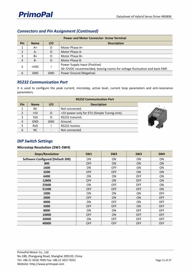
Connectors and Pin Assignment (Continued)
Power and Motor Connector- Screw Terminal
Pin Name I/O Description
1 A+ O Motor Phase A+
2 A- O Motor Phase A-
3 B+ O Motor Phase B+
4 B- O Motor Phase B-
5 +VDC I Power Supply Input (Positive) 30-72VDC recommended, leaving rooms for voltage fluctuation and back-EMF.
6 GND GND Power Ground (Negative)
RS232 Communication Port
It is used to configure the peak current, microstep, active level, current loop parameters and anti-resonance parameters.
RS232 Communication Port
Pin Name I/O Description
1 NC - Not connected.
2 +5V O +5V power only for STU (Simple Tuning Unit).
3 TxD O RS232 transmit.
4 GND GND Ground.
5 RxD I RS232 receive.
6 NC - Not connected.
DIP Switch Settings
Microstep Resolution (SW1-SW4)
Steps/Revolution SW1 SW2 SW3 SW4
Software Configured (Default 200) ON ON ON ON
800 OFF ON ON ON
1600 ON OFF ON ON
3200 OFF OFF ON ON
6400 ON ON OFF ON
12800 OFF ON OFF ON
25600 ON OFF OFF ON
51200 OFF OFF OFF ON
1000 ON ON ON OFF
2000 OFF ON ON OFF
4000 ON OFF ON OFF
5000 OFF OFF ON OFF
8000 ON ON OFF OFF
10000 OFF ON OFF OFF
20000 ON OFF OFF OFF
40000 OFF OFF OFF OFF
Datasheet of Hybrid Servo Drive HBS806
PrimoPal Motor Co., Ltd. No.188, Zhangyang Road, Shanghai 200120, China Tel: +86 21 5018 7836 Fax: +86 21 5017 9351 Page 12 of 37 Website: http://www.primopal.com
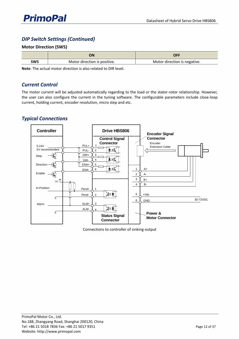
DIP Switch Settings (Continued)
Motor Direction (SW5)
ON OFF
SW5 Motor direction is positive. Motor direction is negative.
Note: The actual motor direction is also related to DIR level.
Current Control
The motor current will be adjusted automatically regarding to the load or the stator-rotor relationship. However, the user can also configure the current in the tuning software. The configurable parameters include close-loop current, holding current, encoder resolution, micro step and etc.
Typical Connections
Connections to controller of sinking output
Drive HBS806
GND
PUL+ 1
DIR+ 3
PUL-
DIR-
2
4
Pend+
A+
A-
B+
+Vdc
Encoder SignalConnector
1
1
2
3
5
6
ENA+ 5
ENA- 6
2Pend-
Encoder
Extension Cable
Power &Motor Connector
30-72VDC
5-24V
5V recommended
Step
Direction
Enable
Alarm
Controller
5V
ALM+ 3
4ALM-
In-Position
Status SignalConnector
4 B-
Control SignalConnector
Datasheet of Hybrid Servo Drive HBS806
PrimoPal Motor Co., Ltd. No.188, Zhangyang Road, Shanghai 200120, China Tel: +86 21 5018 7836 Fax: +86 21 5017 9351 Page 13 of 37 Website: http://www.primopal.com
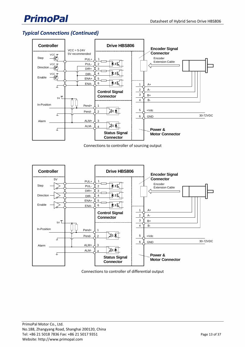
Typical Connections (Continued)
Connections to controller of sourcing output
Connections to controller of differential output
Drive HBS806
GND
A+
A-
B+
+Vdc
Encoder SignalConnector
1
2
3
5
6
Encoder
Extension Cable
Power &Motor Connector
30-72VDC
Controller
Control SignalConnector
4 B-
PUL+ 1
DIR+ 3
PUL-
DIR-
2
4
ENA+ 5
ENA- 6
VCC = 5-24V
5V recommended
Step
Direction
Enable
VCC
VCC
VCC
Pend+ 1
2Pend-
Alarm
5V
ALM+ 3
4ALM-
In-Position
Status SignalConnector
Drive HBS806
GND
A+
A-
B+
+Vdc
Encoder SignalConnector
1
2
3
5
6
EncoderExtension Cable
Power &Motor Connector
30-72VDC
Controller
Control SignalConnector
4 B-
PUL+ 1
DIR+ 3
PUL-
DIR-
2
4
ENA+ 5
ENA- 6
5V
Step
Direction
Enable
Pend+ 1
2Pend-
Alarm
5V
ALM+ 3
4ALM-
In-Position
Status SignalConnector
Datasheet of Hybrid Servo Drive HBS806AC
PrimoPal Motor Co., Ltd. No.188, Zhangyang Road, Shanghai 200120, China Tel: +86 21 5018 7836 Fax: +86 21 5017 9351 Page 14 of 37 Website: http://www.primopal.com
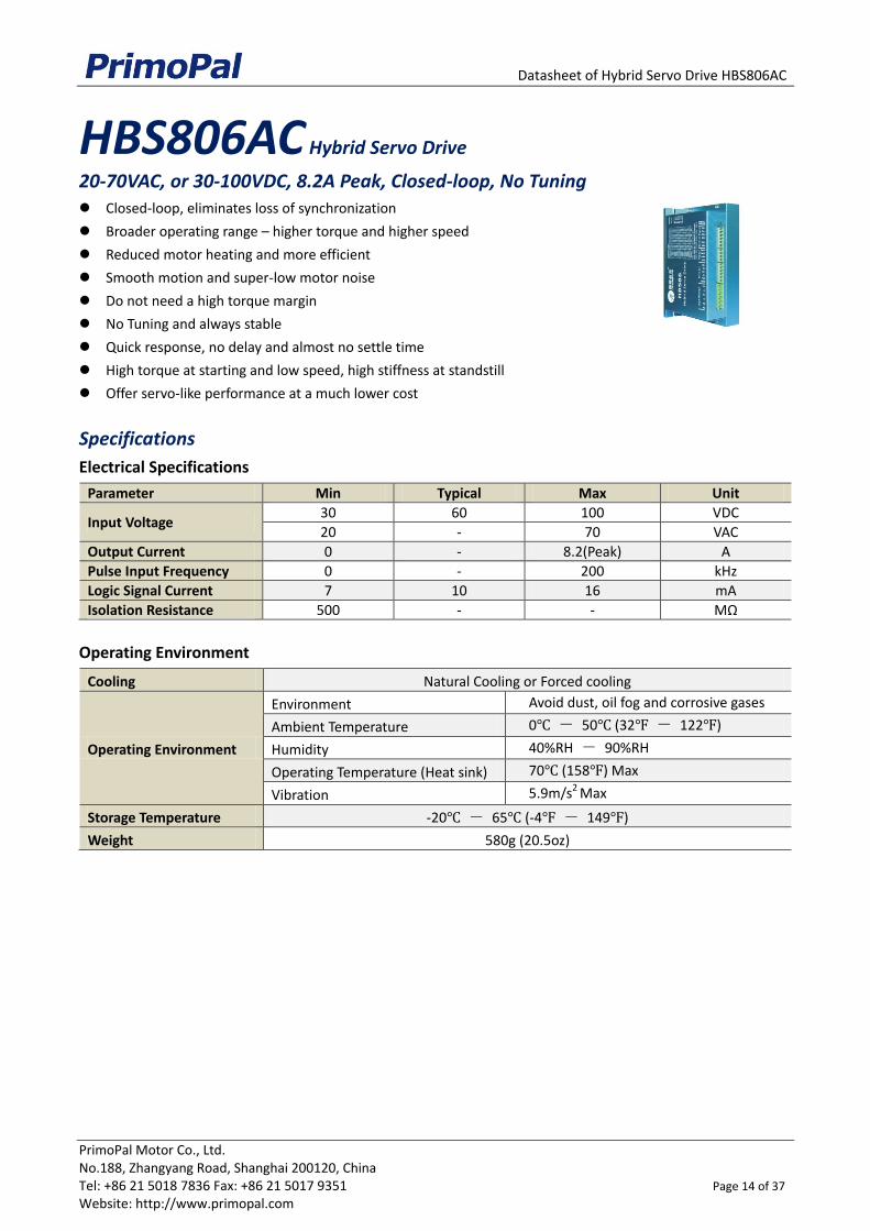
HBS806AC Hybrid Servo Drive
20-70VAC, or 30-100VDC, 8.2A Peak, Closed-loop, No Tuning
Closed-loop, eliminates loss of synchronization
Broader operating range – higher torque and higher speed
Reduced motor heating and more efficient
Smooth motion and super-low motor noise
Do not need a high torque margin
No Tuning and always stable
Quick response, no delay and almost no settle time
High torque at starting and low speed, high stiffness at standstill
Offer servo-like performance at a much lower cost
Specifications
Electrical Specifications
Parameter Min Typical Max Unit
Input Voltage 30 60 100 VDC
20 - 70 VAC
Output Current 0 - 8.2(Peak) A
Pulse Input Frequency 0 - 200 kHz
Logic Signal Current 7 10 16 mA
Isolation Resistance 500 - - MΩ
Operating Environment
Cooling Natural Cooling or Forced cooling
Operating Environment
Environment Avoid dust, oil fog and corrosive gases
Ambient Temperature 0℃ - 50℃ (32℉ - 122℉)
Humidity 40%RH - 90%RH
Operating Temperature (Heat sink) 70℃ (158℉) Max
Vibration 5.9m/s2 Max
Storage Temperature -20℃ - 65℃ (-4℉ - 149℉)
Weight 580g (20.5oz)
Datasheet of Hybrid Servo Drive HBS806AC
PrimoPal Motor Co., Ltd. No.188, Zhangyang Road, Shanghai 200120, China Tel: +86 21 5018 7836 Fax: +86 21 5017 9351 Page 15 of 37 Website: http://www.primopal.com
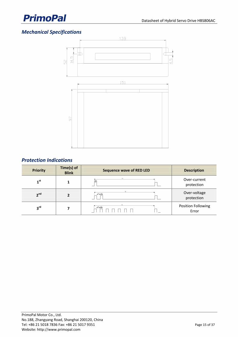
Mechanical Specifications
Protection Indications
Priority Time(s) of
Blink Sequence wave of RED LED Description
1st 1
Over-current protection
2nd 2
Over-voltage protection
3rd 7
Position Following Error
0.2S0.3S
5S
0 . 2 S 0 . 3 S 5 S
0 . 2 S 5 S
Datasheet of Hybrid Servo Drive HBS806AC
PrimoPal Motor Co., Ltd. No.188, Zhangyang Road, Shanghai 200120, China Tel: +86 21 5018 7836 Fax: +86 21 5017 9351 Page 16 of 37 Website: http://www.primopal.com
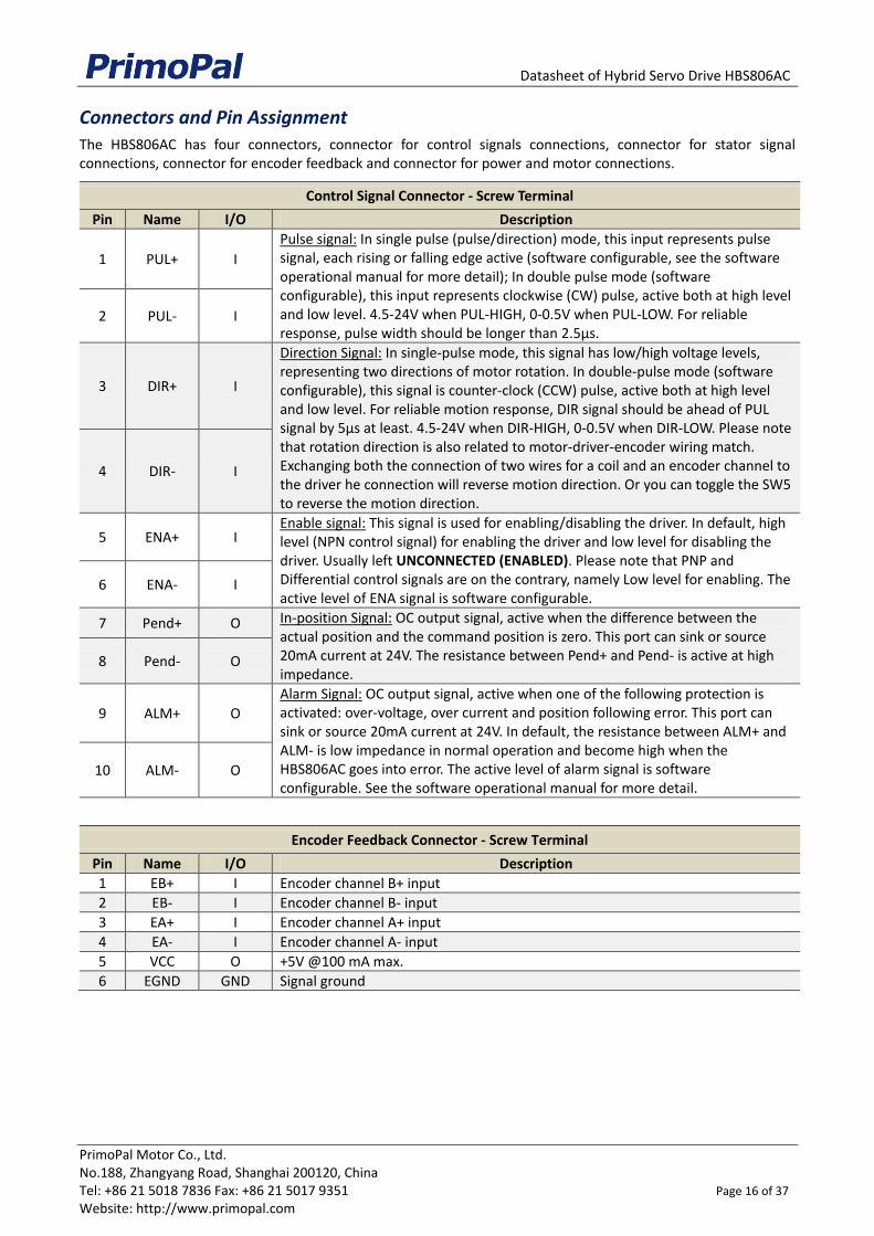
Connectors and Pin Assignment
The HBS806AC has four connectors, connector for control signals connections, connector for stator signal connections, connector for encoder feedback and connector for power and motor connections.
Control Signal Connector - Screw Terminal
Pin Name I/O Description
1 PUL+ I
Pulse signal: In single pulse (pulse/direction) mode, this input represents pulse signal, each rising or falling edge active (software configurable, see the software operational manual for more detail); In double pulse mode (software configurable), this input represents clockwise (CW) pulse, active both at high level and low level. 4.5-24V when PUL-HIGH, 0-0.5V when PUL-LOW. For reliable response, pulse width should be longer than 2.5μs.
2 PUL- I
3 DIR+ I
Direction Signal: In single-pulse mode, this signal has low/high voltage levels, representing two directions of motor rotation. In double-pulse mode (software configurable), this signal is counter-clock (CCW) pulse, active both at high level and low level. For reliable motion response, DIR signal should be ahead of PUL signal by 5μs at least. 4.5-24V when DIR-HIGH, 0-0.5V when DIR-LOW. Please note that rotation direction is also related to motor-driver-encoder wiring match. Exchanging both the connection of two wires for a coil and an encoder channel to the driver he connection will reverse motion direction. Or you can toggle the SW5 to reverse the motion direction.
4 DIR- I
5 ENA+ I Enable signal: This signal is used for enabling/disabling the driver. In default, high level (NPN control signal) for enabling the driver and low level for disabling the driver. Usually left UNCONNECTED (ENABLED). Please note that PNP and Differential control signals are on the contrary, namely Low level for enabling. The active level of ENA signal is software configurable.
6 ENA- I
7 Pend+ O In-position Signal: OC output signal, active when the difference between the actual position and the command position is zero. This port can sink or source 20mA current at 24V. The resistance between Pend+ and Pend- is active at high impedance.
8 Pend- O
9 ALM+ O
Alarm Signal: OC output signal, active when one of the following protection is activated: over-voltage, over current and position following error. This port can sink or source 20mA current at 24V. In default, the resistance between ALM+ and ALM- is low impedance in normal operation and become high when the HBS806AC goes into error. The active level of alarm signal is software configurable. See the software operational manual for more detail.
10 ALM- O
Encoder Feedback Connector - Screw Terminal
Pin Name I/O Description
1 EB+ I Encoder channel B+ input
2 EB- I Encoder channel B- input
3 EA+ I Encoder channel A+ input
4 EA- I Encoder channel A- input
5 VCC O +5V @100 mA max.
6 EGND GND Signal ground
Datasheet of Hybrid Servo Drive HBS806AC
PrimoPal Motor Co., Ltd. No.188, Zhangyang Road, Shanghai 200120, China Tel: +86 21 5018 7836 Fax: +86 21 5017 9351 Page 17 of 37 Website: http://www.primopal.com
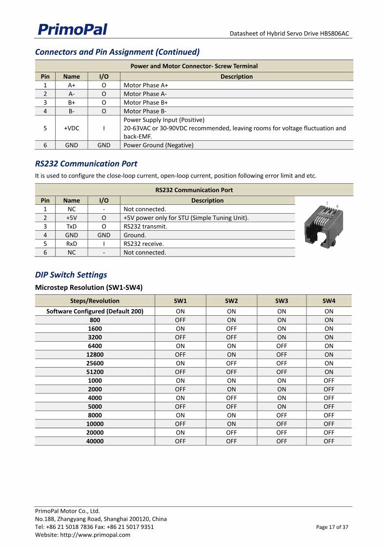
Connectors and Pin Assignment (Continued)
Power and Motor Connector- Screw Terminal
Pin Name I/O Description
1 A+ O Motor Phase A+
2 A- O Motor Phase A-
3 B+ O Motor Phase B+
4 B- O Motor Phase B-
5 +VDC I Power Supply Input (Positive) 20-63VAC or 30-90VDC recommended, leaving rooms for voltage fluctuation and back-EMF.
6 GND GND Power Ground (Negative)
RS232 Communication Port
It is used to configure the close-loop current, open-loop current, position following error limit and etc.
RS232 Communication Port
Pin Name I/O Description
1 NC - Not connected.
2 +5V O +5V power only for STU (Simple Tuning Unit).
3 TxD O RS232 transmit.
4 GND GND Ground.
5 RxD I RS232 receive.
6 NC - Not connected.
DIP Switch Settings
Microstep Resolution (SW1-SW4)
Steps/Revolution SW1 SW2 SW3 SW4
Software Configured (Default 200) ON ON ON ON
800 OFF ON ON ON
1600 ON OFF ON ON
3200 OFF OFF ON ON
6400 ON ON OFF ON
12800 OFF ON OFF ON
25600 ON OFF OFF ON
51200 OFF OFF OFF ON
1000 ON ON ON OFF
2000 OFF ON ON OFF
4000 ON OFF ON OFF
5000 OFF OFF ON OFF
8000 ON ON OFF OFF
10000 OFF ON OFF OFF
20000 ON OFF OFF OFF
40000 OFF OFF OFF OFF

Datasheet of Hybrid Servo Drive HBS806AC
PrimoPal Motor Co., Ltd. No.188, Zhangyang Road, Shanghai 200120, China Tel: +86 21 5018 7836 Fax: +86 21 5017 9351 Page 18 of 37 Website: http://www.primopal.com
DIP Switch Settings (Continued)
Motor Direction (SW5)
ON OFF
SW5 Motor direction is positive. Motor direction is negative.
Note: The actual motor direction is also related to DIR level.
Motor Selection (SW6)
It is reserved for future use. Now it has no function for SW6.
Current Control
The motor current will be adjusted automatically regarding to the load or the stator-rotor relationship. However, the user can also configure the current in the tuning software. The configurable parameters include close-loop current, holding current, encoder resolution, micro step and etc.
Typical Connections
Connections to controller of sinking output
Drive HBS806AC
GND
PUL+ 1
DIR+ 3
PUL-
DIR-
2
4
A+
A-
B+
+Vdc
Encoder SignalConnector
1
2
3
5
6
ENA+ 5
ENA- 6
EncoderExtension Cable
Power &Motor Connector
~20-63VAC Or 30-90VDC recommended,leaving rooms for voltage fluctuation andback EMF of motor
5-24V5V recommended
Step
Direction
Enable
Controller
Control SignalConnector
4 B-
Pend+ 1
2Pend-
Alarm
5V
ALM+ 3
4ALM-
In-Position
Status SignalConnector
Datasheet of Hybrid Servo Drive HBS806AC
PrimoPal Motor Co., Ltd. No.188, Zhangyang Road, Shanghai 200120, China Tel: +86 21 5018 7836 Fax: +86 21 5017 9351 Page 19 of 37 Website: http://www.primopal.com
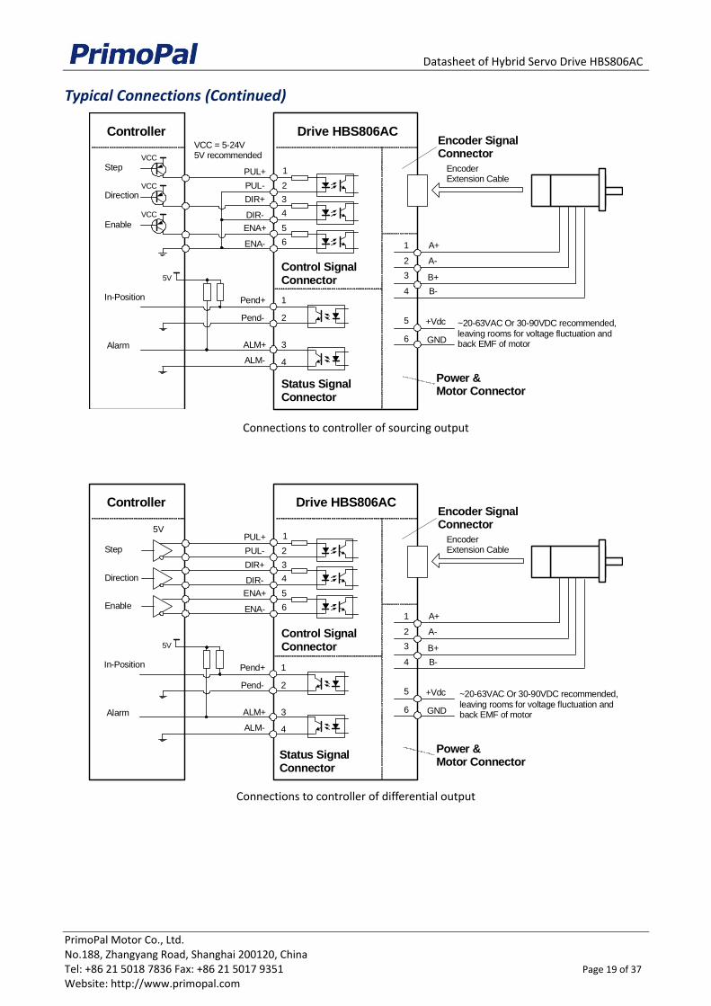
Typical Connections (Continued)
Connections to controller of sourcing output
Connections to controller of differential output
Drive HBS806AC
GND
A+
A-
B+
+Vdc
Encoder SignalConnector
1
2
3
5
6
EncoderExtension Cable
Power &Motor Connector
Controller
Control SignalConnector
4 B-
PUL+ 1
DIR+ 3
PUL-
DIR-
2
4
ENA+ 5
ENA- 6
VCC = 5-24V5V recommended
Step
Direction
Enable
VCC
VCC
VCC
Pend+ 1
2Pend-
Alarm
5V
ALM+ 3
4ALM-
In-Position
Status SignalConnector
~20-63VAC Or 30-90VDC recommended,leaving rooms for voltage fluctuation andback EMF of motor
Drive HBS806AC
GND
A+
A-
B+
+Vdc
Encoder SignalConnector
1
2
3
5
6
EncoderExtension Cable
Power &Motor Connector
Controller
Control SignalConnector
4 B-
PUL+ 1
DIR+ 3
PUL-
DIR-
2
4
ENA+ 5
ENA- 6
5V
Step
Direction
Enable
Pend+ 1
2Pend-
Alarm
5V
ALM+ 3
4ALM-
In-Position
Status SignalConnector
~20-63VAC Or 30-90VDC recommended,leaving rooms for voltage fluctuation andback EMF of motor
Datasheet of Hybrid Servo Drive HBS1108AC
PrimoPal Motor Co., Ltd. No.188, Zhangyang Road, Shanghai 200120, China Tel: +86 21 5018 7836 Fax: +86 21 5017 9351 Page 20 of 37 Website: http://www.primopal.com
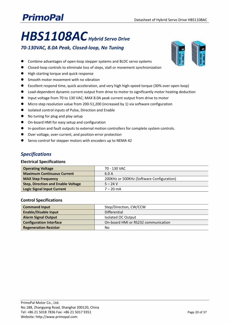
HBS1108AC Hybrid Servo Drive
70-130VAC, 8.0A Peak, Closed-loop, No Tuning
Combine advantages of open-loop stepper systems and BLDC servo systems
Closed-loop controls to eliminate loss of steps, stall or movement synchronization
High starting torque and quick response
Smooth motor movement with no vibration
Excellent respond time, quick acceleration, and very high high-speed torque (30% over open-loop)
Load-dependent dynamic current output from drive to motor to significantly motor heating deduction
Input voltage from 70 to 130 VAC; MAX 8.0A peak current output from drive to motor
Micro step resolution value from 200-51,200 (increased by 1) via software configuration
Isolated control inputs of Pulse, Direction and Enable
No tuning for plug and play setup
On-board HMI for easy setup and configuration
In-position and fault outputs to external motion controllers for complete system controls.
Over voltage, over-current, and position-error protection
Servo control for stepper motors with encoders up to NEMA 42
Specifications
Electrical Specifications
Operating Voltage 70 - 130 VAC
Maximum Continuous Current 6.0 A
MAX Step Frequency 200KHz or 500KHz (Software Configuration)
Step, Direction and Enable Voltage 5 – 24 V
Logic Signal Input Current 7 – 20 mA
Control Specifications
Command Input Step/Direction, CW/CCW
Enable/Disable Input Differential
Alarm Signal Output Isolated OC Output
Configuration Interface On-board HMI or RS232 communication
Regeneration Resistor No
Datasheet of Hybrid Servo Drive HBS1108AC
PrimoPal Motor Co., Ltd. No.188, Zhangyang Road, Shanghai 200120, China Tel: +86 21 5018 7836 Fax: +86 21 5017 9351 Page 21 of 37 Website: http://www.primopal.com
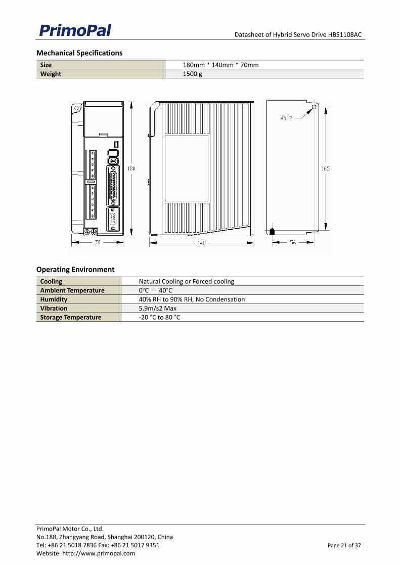
Mechanical Specifications
Size 180mm * 140mm * 70mm
Weight 1500 g
Operating Environment
Cooling Natural Cooling or Forced cooling
Ambient Temperature 0°C - 40°C
Humidity 40% RH to 90% RH, No Condensation
Vibration 5.9m/s2 Max
Storage Temperature -20 °C to 80 °C
Datasheet of Hybrid Servo Drive HBS1108AC
PrimoPal Motor Co., Ltd. No.188, Zhangyang Road, Shanghai 200120, China Tel: +86 21 5018 7836 Fax: +86 21 5017 9351 Page 22 of 37 Website: http://www.primopal.com
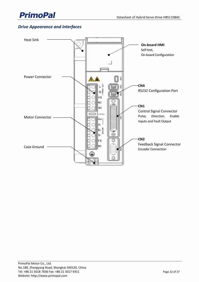
Drive Appearance and Interfaces
Heat Sink
Power Connector
Motor Connector
Case Ground
On-board HMISelf-test,
On-board Configuration
CN4
RS232 Configuration Port
CN1
Control Signal ConnectorPulse, Direction, Enable
Inputs and Fault Output
CN2
Feedback Signal ConnectorEncoder Connection

Datasheet of Hybrid Servo Drive HBS1108AC
PrimoPal Motor Co., Ltd. No.188, Zhangyang Road, Shanghai 200120, China Tel: +86 21 5018 7836 Fax: +86 21 5017 9351 Page 23 of 37 Website: http://www.primopal.com
Connectors and Pin Assignment
CN1 - Control Signal Connector
D-Sub, 26 Pin, Female
Pin Name I/O Description
1 NC - No connection.
2 NC - No connection.
3 PUL+ I
Pulse signal: In single pulse (pulse/direction) mode, this input represents pulse signal, each rising or falling edge active (software configurable); In double pulse mode (software configurable), this input represents clockwise (CW) pulse, active both at high level and low level. 5-24V when PUL-HIGH, 0-0.5V when PUL-LOW. For reliable response, pulse width should be longer than 2.5uS(200K bandwidth) or 1uS(500K bandwidth)
4 PUL- I
5 DIR+ I Direction Signal: In single-pulse mode, this signal has low/high voltage levels, representing two directions of motor rotation. In double-pulse mode (software configurable), this signal is counter-clock (CCW) pulse, active both at high level and low level. For reliable motion response, DIR signal should be ahead of PUL signal by 5μs at least. 5-24V when DIR-HIGH, 0-0.5V when DIR-LOW. The direction signal’s polarity is software configurable.
6 DIR- I
7 ALM+ O Alarm Signal: OC (Open Collector) output signal, activated when one of the following protection is activated: over-voltage, over current, braking error and position following error. They can sink or source MAX 100mA current at 5V. The active impedance of alarm signal is software configurable.
8 ALM- O
9 NC - No connection.
10 NC - No connection.
11 ENA+ O Enable signal: This signal is used for enabling/disabling the driver. By default, high level (NPN control signal) for enabling the driver and low level for disabling the driver. It is usually left UNCONNECTED (ENABLED). Please note that the PNP and Differential control signals are on the contrary, namely Low level for enabling. The active level of ENA signal is software configurable.
12 ENA- O
13 NC - No connection.
14 NC - No connection.
15 NC - No connection.
16 NC - No connection.
17 NC - No connection.
18 NC - No connection.
19 NC - No connection.
20 NC - No connection.
21 NC - No connection.
22 NC - No connection.
23 NC - No connection.
24 NC - No connection.
25 NC - No connection.
26 NC - No connection.
27 NC - No connection.
28 NC - No connection.
29 NC - No connection.
30 NC - No connection.
Datasheet of Hybrid Servo Drive HBS1108AC
PrimoPal Motor Co., Ltd. No.188, Zhangyang Road, Shanghai 200120, China Tel: +86 21 5018 7836 Fax: +86 21 5017 9351 Page 24 of 37 Website: http://www.primopal.com
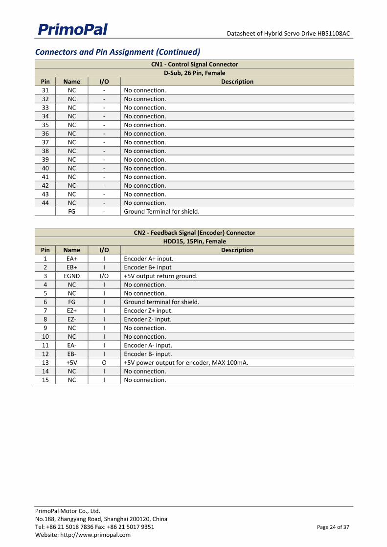
Connectors and Pin Assignment (Continued)
CN1 - Control Signal Connector
D-Sub, 26 Pin, Female
Pin Name I/O Description
31 NC - No connection.
32 NC - No connection.
33 NC - No connection.
34 NC - No connection.
35 NC - No connection.
36 NC - No connection.
37 NC - No connection.
38 NC - No connection.
39 NC - No connection.
40 NC - No connection.
41 NC - No connection.
42 NC - No connection.
43 NC - No connection.
44 NC - No connection.
FG - Ground Terminal for shield.
CN2 - Feedback Signal (Encoder) Connector
HDD15, 15Pin, Female
Pin Name I/O Description
1 EA+ I Encoder A+ input.
2 EB+ I Encoder B+ input
3 EGND I/O +5V output return ground.
4 NC I No connection.
5 NC I No connection.
6 FG I Ground terminal for shield.
7 EZ+ I Encoder Z+ input.
8 EZ- I Encoder Z- input.
9 NC I No connection.
10 NC I No connection.
11 EA- I Encoder A- input.
12 EB- I Encoder B- input.
13 +5V O +5V power output for encoder, MAX 100mA.
14 NC I No connection.
15 NC I No connection.
Datasheet of Hybrid Servo Drive HBS1108AC
PrimoPal Motor Co., Ltd. No.188, Zhangyang Road, Shanghai 200120, China Tel: +86 21 5018 7836 Fax: +86 21 5017 9351 Page 25 of 37 Website: http://www.primopal.com
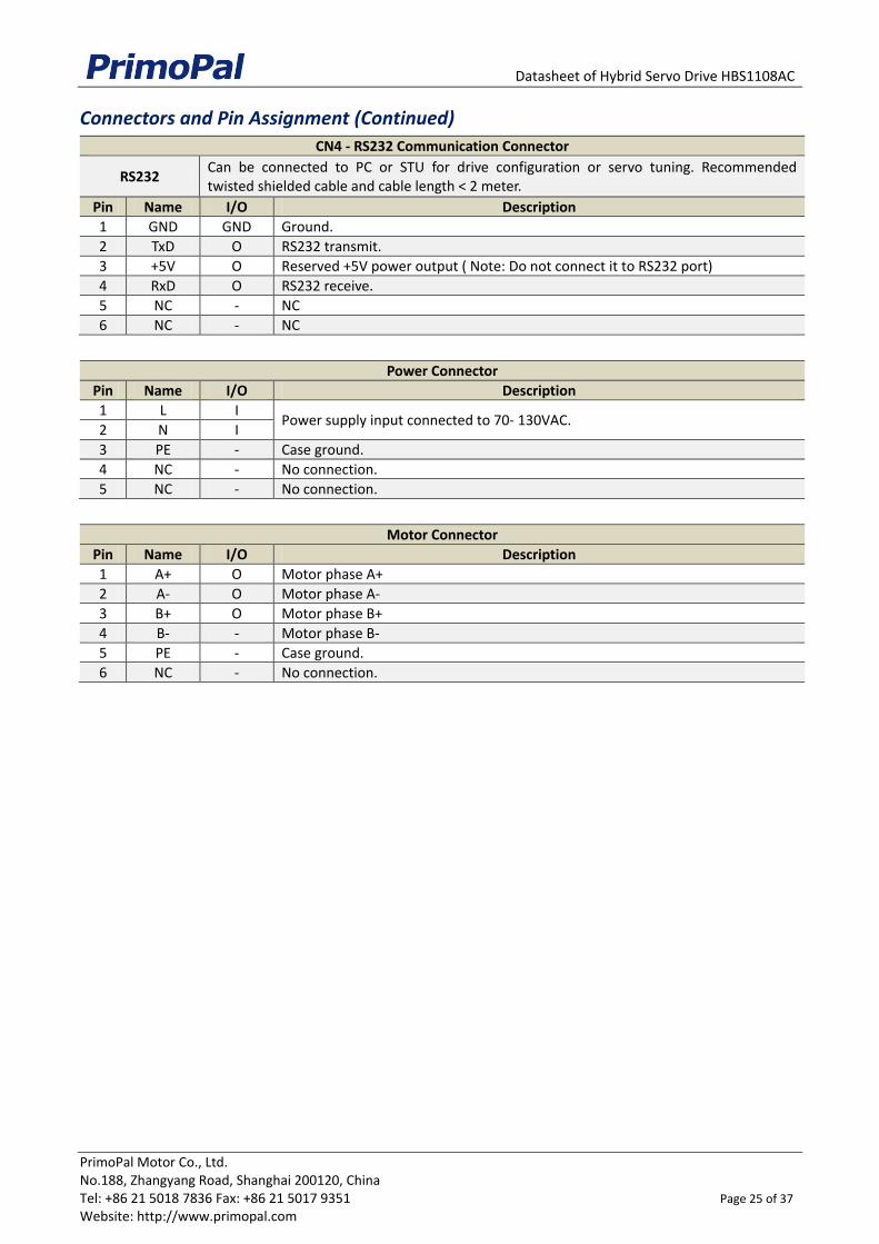
Connectors and Pin Assignment (Continued)
CN4 - RS232 Communication Connector
RS232 Can be connected to PC or STU for drive configuration or servo tuning. Recommended twisted shielded cable and cable length < 2 meter.
Pin Name I/O Description
1 GND GND Ground.
2 TxD O RS232 transmit.
3 +5V O Reserved +5V power output ( Note: Do not connect it to RS232 port)
4 RxD O RS232 receive.
5 NC - NC
6 NC - NC
Power Connector
Pin Name I/O Description
1 L I Power supply input connected to 70- 130VAC.
2 N I
3 PE - Case ground.
4 NC - No connection.
5 NC - No connection.
Motor Connector
Pin Name I/O Description
1 A+ O Motor phase A+
2 A- O Motor phase A-
3 B+ O Motor phase B+
4 B- - Motor phase B-
5 PE - Case ground.
6 NC - No connection.
Datasheet of Hybrid Servo Drive HBS1108AC
PrimoPal Motor Co., Ltd. No.188, Zhangyang Road, Shanghai 200120, China Tel: +86 21 5018 7836 Fax: +86 21 5017 9351 Page 26 of 37 Website: http://www.primopal.com
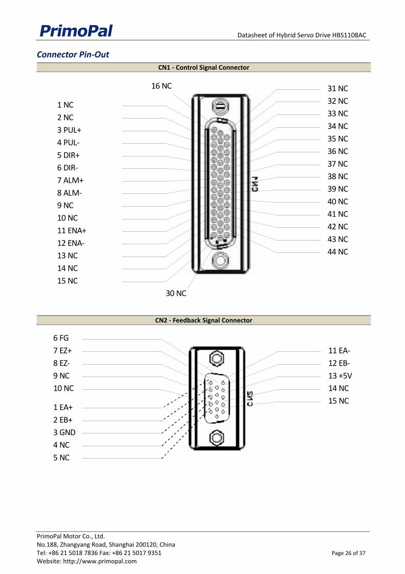
Connector Pin-Out
CN1 - Control Signal Connector
CN2 - Feedback Signal Connector
6 F G
7 E Z +
8 E Z -
9 N C
1 0 N C
1 E A +
2 E B +
3 G N D
4 N C
5 N C
1 1 E A -
1 2 E B -
1 3 + 5 V
1 4 N C
1 5 N C
1 6 N C
3 0 N C
1 5 N C
1 N C
2 N C
1 3 N C
3 P U L +
4 P U L -
5 D I R +
6 D I R -
7 A L M +
8 A L M -
9 N C
1 0 N C
1 1 E N A +
1 2 E N A -
1 4 N C
3 1 N C
4 4 N C
3 3 N C
4 3 N C
4 2 N C
4 1 N C
4 0 N C
3 9 N C
3 8 N C
3 7 N C
3 6 N C
3 5 N C
3 4 N C
3 2 N C
Datasheet of Hybrid Servo Drive HBS1108AC
PrimoPal Motor Co., Ltd. No.188, Zhangyang Road, Shanghai 200120, China Tel: +86 21 5018 7836 Fax: +86 21 5017 9351 Page 27 of 37 Website: http://www.primopal.com
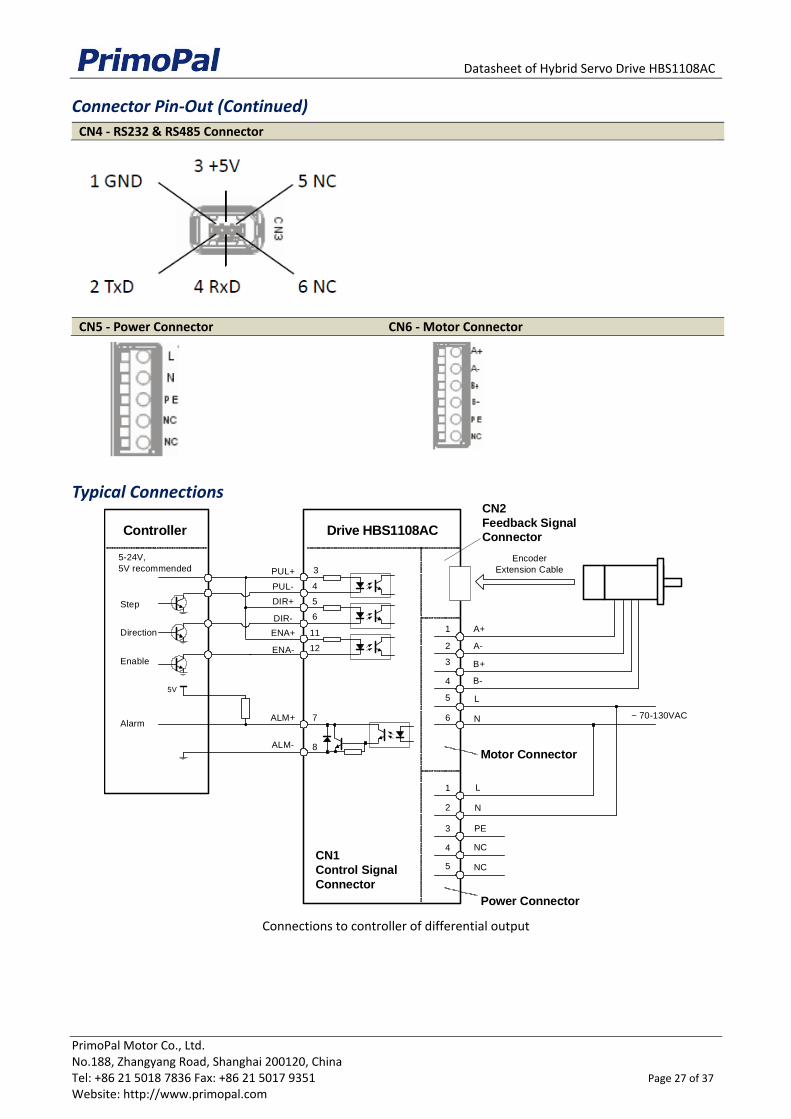
Connector Pin-Out (Continued)
CN4 - RS232 & RS485 Connector
CN5 - Power Connector CN6 - Motor Connector
Typical Connections
Connections to controller of differential output
Drive HBS1108AC
N
PUL+ 3
DIR+ 5
PUL-
DIR-
4
6
ALM+
A+
A-
B+
B-
L
CN2
Feedback SignalConnector
7
CN1
Control Signal
Connector
Power Connector
1
2
3
4
5
6
ENA+ 11
ENA- 12
8ALM-
Encoder
Extension Cable
L
N
PE
NC
NC
1
2
3
4
5
Motor Connector
~ 70-130VAC
5-24V,
5V recommended
Step
Direction
Enable
Alarm
Controller
5V
Datasheet of Hybrid Servo Drive HBS1108AC
PrimoPal Motor Co., Ltd. No.188, Zhangyang Road, Shanghai 200120, China Tel: +86 21 5018 7836 Fax: +86 21 5017 9351 Page 28 of 37 Website: http://www.primopal.com
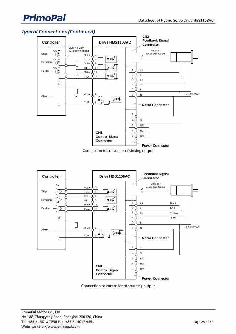
Typical Connections (Continued)
Connection to controller of sinking output
Connection to controller of sourcing output
Drive HBS1108AC
PUL+ 3
DIR+ 5
PUL-
DIR-
4
6
ALM+ 7
CN1
Control Signal
Connector
ENA+ 11
ENA- 12
8ALM-
VCC = 5-24V
5V recommendedStep
Direction
Enable
Alarm
Controller
VCC
VCC
VCC
5V
N
A+
A-
B+
B-
L
CN2
Feedback Signal
Connector
Power Connector
1
2
3
4
5
6
Encoder
Extension Cable
L
N
PE
NC
NC
1
2
3
4
5
Motor Connector
~ 70-130VAC
Drive HBS1108AC
PUL+ 3
DIR+ 5
PUL-
DIR-
4
6
ALM+ 7
CN1
Control Signal
Connector
ENA+ 11
ENA- 12
8ALM-
5V
Step
Direction
Enable
Alarm
Controller
5V
N
A+
A-
B+
B-
L
Feedback Signal
Connector
Power Connector
1
2
3
4
5
6
Encoder
Extension Cable
L
N
PE
NC
NC
1
2
3
4
5
Motor Connector
~ 70-130VAC
Black
Red
Yellow
Blue

Datasheet of Hybrid Servo Drive HBS2206AC
PrimoPal Motor Co., Ltd. No.188, Zhangyang Road, Shanghai 200120, China Tel: +86 21 5018 7836 Fax: +86 21 5017 9351 Page 29 of 37 Website: http://www.primopal.com
HBS2206AC Hybrid Servo Drive
150-230VAC, 6.0A Peak, Close-loop, No Tuning
Combine advantages of open-loop stepper systems and BLDC servo systems
Closed-loop controls to eliminate loss of steps, stall or movement synchronization
High starting torque and quick response
Smooth motor movement with no vibration
Excellent respond time, quick acceleration, and very high high-speed torque (30% over open-loop)
Load-dependent dynamic current output from drive to motor to significantly motor heating deduction
Input voltage from 150 to 230 VAC; MAX 6.0A peak current output from drive to motor
Micro step resolution value from 200-51,200 (increased by 1) via software configuration
Isolated control inputs of Pulse, Direction and Enable
No tuning for plug and play setup
On-board HMI for easy setup and configuration
In-position and fault outputs to external motion controllers for complete system controls.
Over voltage, over-current, and position-error protection
Servo control for stepper motors with encoders up to NEMA 42
Specifications
Electrical Specifications
Operating Voltage 150 - 230 VAC
Maximum Continuous Current 6.0 A
MAX Step Frequency 200KHz or 500KHz (Software Configuration)
Step, Direction and Enable Voltage 5 – 24 V
Logic Signal Input Current 7 – 20 mA
Control Specifications
Command Input Step/Direction, CW/CCW
Enable/Disable Input Differential
Alarm Signal Output Isolated OC Output
Configuration Interface On-board HMI or RS232 communication
Regeneration Resistor Built-in ( 50 Ohm, 100W), Support External

Datasheet of Hybrid Servo Drive HBS2206AC
PrimoPal Motor Co., Ltd. No.188, Zhangyang Road, Shanghai 200120, China Tel: +86 21 5018 7836 Fax: +86 21 5017 9351 Page 30 of 37 Website: http://www.primopal.com
Mechanical Specifications
Size 180mm * 140mm * 70mm
Weight 1500 g
Operating Environment
Cooling Natural Cooling or Forced cooling
Ambient Temperature 0°C - 40°C
Humidity 40% RH to 90% RH, No Condensation
Vibration 5.9m/s2 Max
Storage Temperature -20 °C to 80 °C
Datasheet of Hybrid Servo Drive HBS2206AC
PrimoPal Motor Co., Ltd. No.188, Zhangyang Road, Shanghai 200120, China Tel: +86 21 5018 7836 Fax: +86 21 5017 9351 Page 31 of 37 Website: http://www.primopal.com
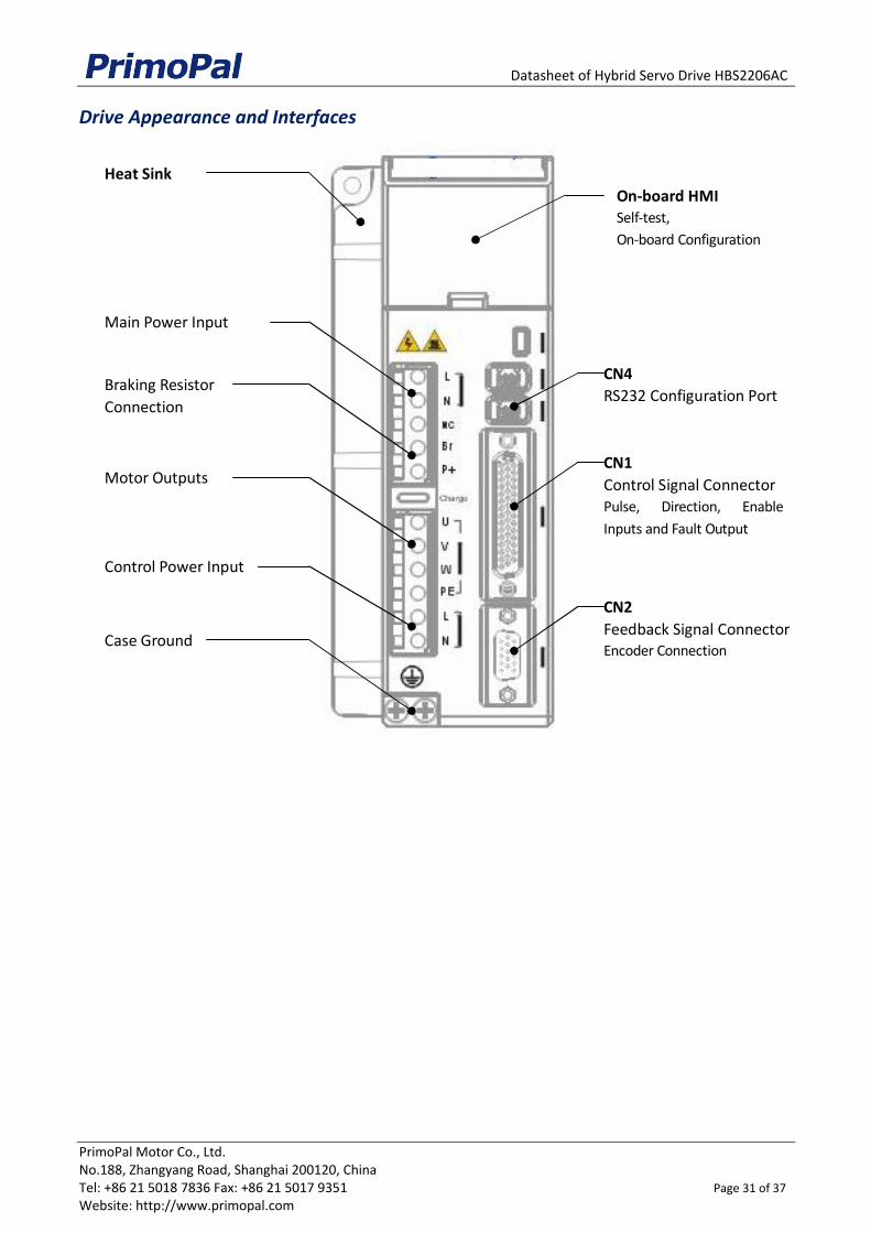
Drive Appearance and Interfaces
Heat Sink
Main Power Input
Motor Outputs
Case Ground
On-board HMISelf-test,
On-board Configuration
CN4
RS232 Configuration Port
CN1
Control Signal ConnectorPulse, Direction, Enable
Inputs and Fault Output
CN2
Feedback Signal ConnectorEncoder Connection
Braking Resistor
Connection
Control Power Input

Datasheet of Hybrid Servo Drive HBS2206AC
PrimoPal Motor Co., Ltd. No.188, Zhangyang Road, Shanghai 200120, China Tel: +86 21 5018 7836 Fax: +86 21 5017 9351 Page 32 of 37 Website: http://www.primopal.com
Connectors and Pin Assignment
CN1 - Control Signal Connector
D-Sub, 26 Pin, Female
Pin Name I/O Description
1 NC - No connection.
2 NC - No connection.
3 PUL+ I
Pulse signal: In single pulse (pulse/direction) mode, this input represents pulse signal, each rising or falling edge active (software configurable); In double pulse mode (software configurable), this input represents clockwise (CW) pulse, active both at high level and low level. 5-24V when PUL-HIGH, 0-0.5V when PUL-LOW. For reliable response, pulse width should be longer than 2.5uS(200K bandwidth) or 1uS(500K bandwidth)
4 PUL- I
5 DIR+ I Direction Signal: In single-pulse mode, this signal has low/high voltage levels, representing two directions of motor rotation. In double-pulse mode (software configurable), this signal is counter-clock (CCW) pulse, active both at high level and low level. For reliable motion response, DIR signal should be ahead of PUL signal by 5μs at least. 5-24V when DIR-HIGH, 0-0.5V when DIR-LOW. The direction signal’s polarity is software configurable.
6 DIR- I
7 ALM+ O Alarm Signal: OC (Open Collector) output signal, activated when one of the following protection is activated: over-voltage, over current, braking error and position following error. They can sink or source MAX 100mA current at 5V. The active impedance of alarm signal is software configurable.
8 ALM- O
9 NC - No connection.
10 NC - No connection.
11 ENA+ O Enable signal: This signal is used for enabling/disabling the driver. By default, high level (NPN control signal) for enabling the driver and low level for disabling the driver. It is usually left UNCONNECTED (ENABLED). Please note that the PNP and Differential control signals are on the contrary, namely Low level for enabling. The active level of ENA signal is software configurable.
12 ENA- O
13 NC - No connection.
14 NC - No connection.
15 NC - No connection.
16 NC - No connection.
17 NC - No connection.
18 NC - No connection.
19 NC - No connection.
20 NC - No connection.
21 NC - No connection.
22 NC - No connection.
23 NC - No connection.
24 NC - No connection.
25 NC - No connection.
26 NC - No connection.
27 NC - No connection.
28 NC - No connection.
29 NC - No connection.
30 NC - No connection.

Datasheet of Hybrid Servo Drive HBS2206AC
PrimoPal Motor Co., Ltd. No.188, Zhangyang Road, Shanghai 200120, China Tel: +86 21 5018 7836 Fax: +86 21 5017 9351 Page 33 of 37 Website: http://www.primopal.com
Connectors and Pin Assignment (Continued)
CN1 - Control Signal Connector
D-Sub, 26 Pin, Female
Pin Name I/O Description
31 NC - No connection.
32 NC - No connection.
33 NC - No connection.
34 NC - No connection.
35 NC - No connection.
36 NC - No connection.
37 NC - No connection.
38 NC - No connection.
39 NC - No connection.
40 NC - No connection.
41 NC - No connection.
42 NC - No connection.
43 NC - No connection.
44 NC - No connection.
FG - Ground Terminal for shield.
CN2 - Feedback Signal (Encoder) Connector
HDD15, 15Pin, Female
Pin Name I/O Description
1 EA+ I Encoder A+ input.
2 EB+ I Encoder B+ input
3 EGND I/O +5V output return ground.
4 NC I No connection.
5 NC I No connection.
6 FG I Ground terminal for shield.
7 EZ+ I Encoder Z+ input.
8 EZ- I Encoder Z- input.
9 NC I No connection.
10 NC I No connection.
11 EA- I Encoder A- input.
12 EB- I Encoder B- input.
13 +5V O +5V power output for encoder, MAX 100mA.
14 NC I No connection.
15 NC I No connection.

Datasheet of Hybrid Servo Drive HBS2206AC
PrimoPal Motor Co., Ltd. No.188, Zhangyang Road, Shanghai 200120, China Tel: +86 21 5018 7836 Fax: +86 21 5017 9351 Page 34 of 37 Website: http://www.primopal.com
Connectors and Pin Assignment (Continued)
CN4 - RS232 Communication Connector
RS232 Can be connected to PC or STU for drive configuration or servo tuning. Recommended twisted shielded cable and cable length < 2 meter.
Pin Name I/O Description
1 GND GND Ground.
2 TxD O RS232 transmit.
3 +5V O Reserved +5V power output ( Note: Do not connect it to RS232 port)
4 RxD O RS232 receive.
5 NC - NC
6 NC - NC
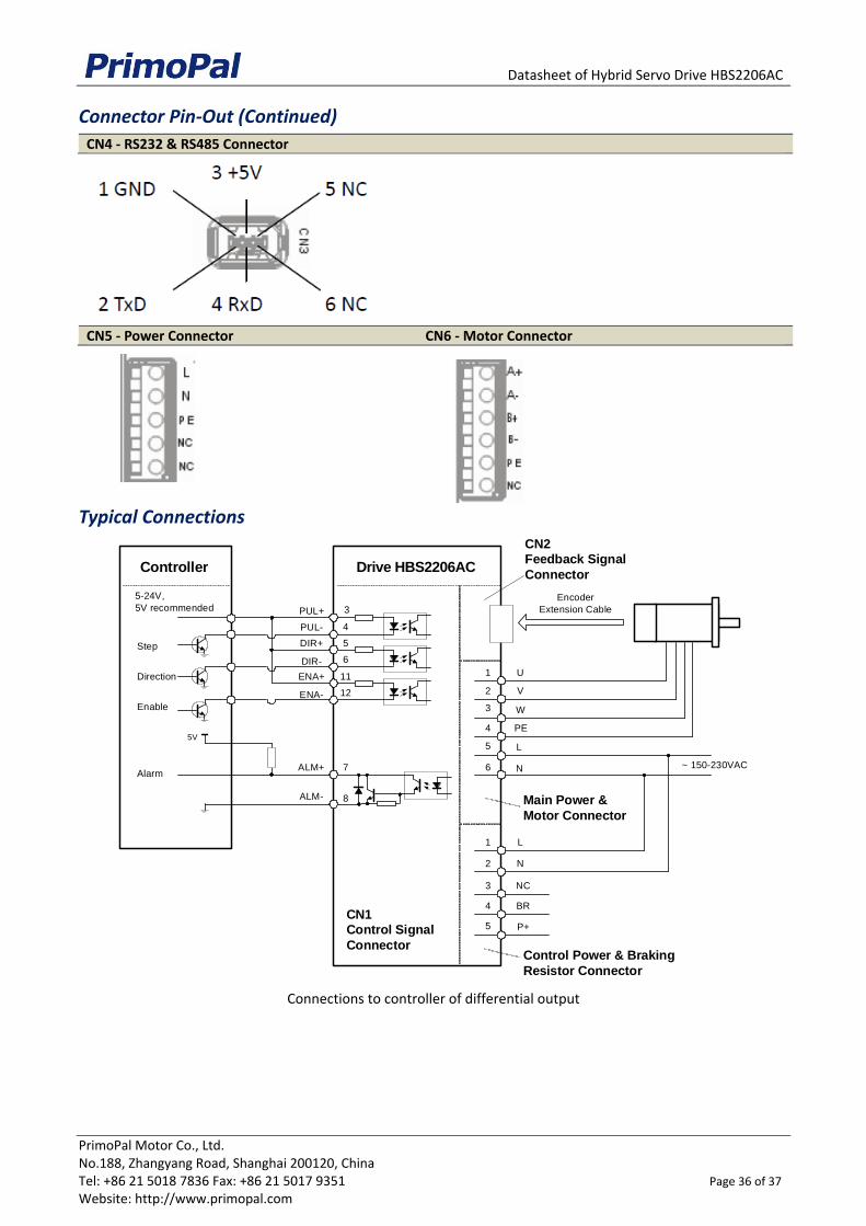
Main Power Supply Connector
Pin Name I/O Description
1 L I
Main power supply input connected to 150- 230VAC. 2 N I
3 NC -
4 BR1 I External regeneration resistor connection.
5 P+ O Internal DC bus voltage output. The regeneration resistor should be connected between BR1 and P+.
Motor & Control Power Supply Connector
Pin Name I/O Description
1 U O Motor phase U
2 V O Motor phase V
3 W O Motor phase W
4 PE - Case ground
5 L I Control Power Supply from 150VAC to 230VAC.
6 N I

Datasheet of Hybrid Servo Drive HBS2206AC
PrimoPal Motor Co., Ltd. No.188, Zhangyang Road, Shanghai 200120, China Tel: +86 21 5018 7836 Fax: +86 21 5017 9351 Page 35 of 37 Website: http://www.primopal.com
Connector Pin-Out
CN1 - Control Signal Connector
CN2 - Feedback Signal Connector
6 F G
7 E Z +
8 E Z -
9 N C
1 0 N C
1 E A +
2 E B +
3 G N D
4 N C
5 N C
1 1 E A -
1 2 E B -
1 3 + 5 V
1 4 N C
1 5 N C
1 6 N C
3 0 N C
1 5 N C
1 N C
2 N C
1 3 N C
3 P U L +
4 P U L -
5 D I R +
6 D I R -
7 A L M +
8 A L M -
9 N C
1 0 N C
1 1 E N A +
1 2 E N A -
1 4 N C
3 1 N C
4 4 N C
3 3 N C
4 3 N C
4 2 N C
4 1 N C
4 0 N C
3 9 N C
3 8 N C
3 7 N C
3 6 N C
3 5 N C
3 4 N C
3 2 N C
Datasheet of Hybrid Servo Drive HBS2206AC
PrimoPal Motor Co., Ltd. No.188, Zhangyang Road, Shanghai 200120, China Tel: +86 21 5018 7836 Fax: +86 21 5017 9351 Page 36 of 37 Website: http://www.primopal.com
Connector Pin-Out (Continued)
CN4 - RS232 & RS485 Connector
CN5 - Power Connector CN6 - Motor Connector
Typical Connections
Connections to controller of differential output
Drive HBS2206AC
N
PUL+ 3
DIR+ 5
PUL-
DIR-
4
6
ALM+
U
V
W
PE
L
CN2Feedback Signal
Connector
7
CN1Control Signal
ConnectorControl Power & Braking
Resistor Connector
1
2
3
4
5
6
ENA+ 11
ENA- 12
8ALM-
Encoder
Extension Cable
L
N
NC
BR
P+
1
2
3
4
5
Main Power &
Motor Connector
~ 150-230VAC
5-24V,
5V recommended
Step
Direction
Enable
Alarm
Controller
5V

Datasheet of Hybrid Servo Drive HBS2206AC
PrimoPal Motor Co., Ltd. No.188, Zhangyang Road, Shanghai 200120, China Tel: +86 21 5018 7836 Fax: +86 21 5017 9351 Page 37 of 37 Website: http://www.primopal.com
Typical Connections (Continued)
Connection to controller of sinking output
Connection to controller of sourcing output
Drive HBS2206AC
N
PUL+ 3
DIR+ 5
PUL-
DIR-
4
6
ALM+
U
V
W
PE
L
CN2Feedback Signal
Connector
7
CN1
Control SignalConnector
Control Power & Braking
Resistor Connector
1
2
3
4
5
6
ENA+ 11
ENA- 12
8ALM-
Encoder
Extension Cable
L
N
NC
BR
P+
1
2
3
4
5
Main Power &
Motor Connector
~ 150-230VAC
VCC = 5-24V
5V recommendedStep
Direction
Enable
Alarm
Controller
VCC
VCC
VCC
5V
Drive HBS2206AC
N
PUL+ 3
DIR+ 5
PUL-
DIR-
4
6
ALM+
U
V
W
PE
L
CN2Feedback Signal
Connector
7
CN1
Control SignalConnector
Control Power & Braking
Resistor Connector
1
2
3
4
5
6
ENA+ 11
ENA- 12
8ALM-
Encoder
Extension Cable
L
N
NC
BR
P+
1
2
3
4
5
Main Power &
Motor Connector
~ 150-230VAC
5V
Step
Direction
Enable
Alarm
Controller
5V