Embed Size (px)
Citation preview
Princeton University BIM Specification
January 26, 2012 1
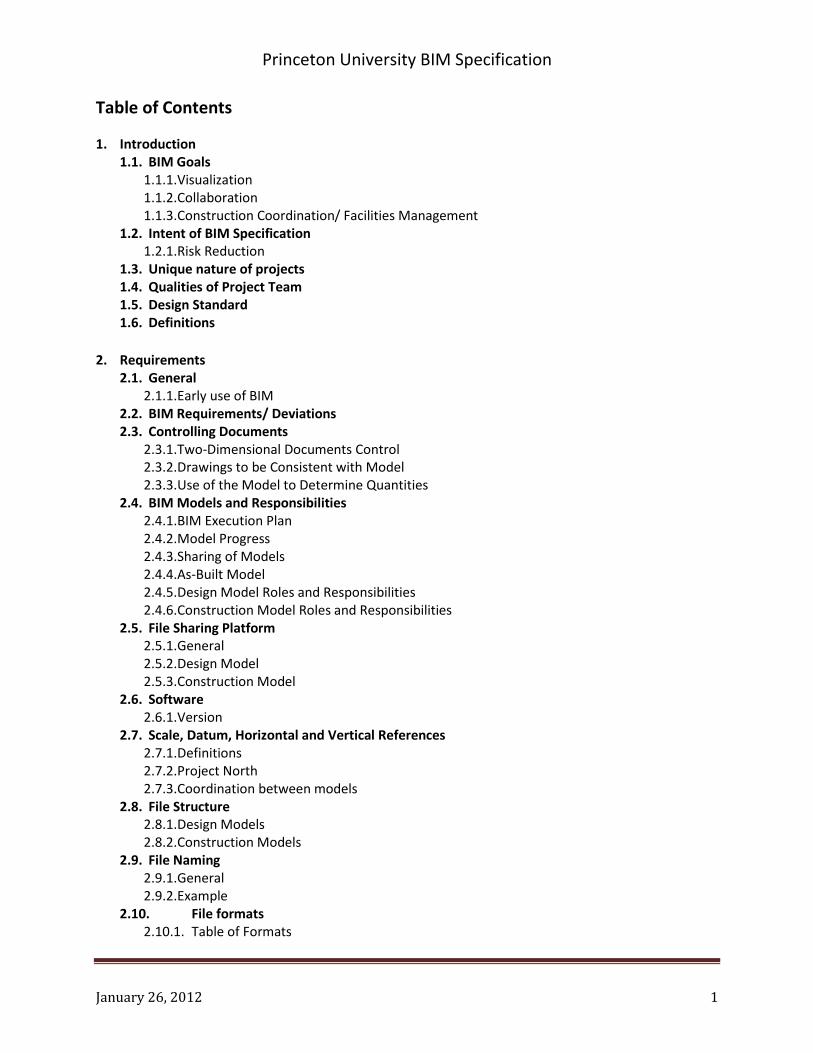
Table of Contents
1. Introduction 1.1. BIM Goals
1.1.1. Visualization 1.1.2. Collaboration 1.1.3. Construction Coordination/ Facilities Management
1.2. Intent of BIM Specification 1.2.1. Risk Reduction
1.3. Unique nature of projects 1.4. Qualities of Project Team 1.5. Design Standard 1.6. Definitions
2. Requirements
2.1. General 2.1.1. Early use of BIM
2.2. BIM Requirements/ Deviations 2.3. Controlling Documents
2.3.1. Two-Dimensional Documents Control 2.3.2. Drawings to be Consistent with Model 2.3.3. Use of the Model to Determine Quantities
2.4. BIM Models and Responsibilities 2.4.1. BIM Execution Plan 2.4.2. Model Progress 2.4.3. Sharing of Models 2.4.4. As-Built Model 2.4.5. Design Model Roles and Responsibilities 2.4.6. Construction Model Roles and Responsibilities
2.5. File Sharing Platform 2.5.1. General 2.5.2. Design Model 2.5.3. Construction Model
2.6. Software 2.6.1. Version
2.7. Scale, Datum, Horizontal and Vertical References 2.7.1. Definitions 2.7.2. Project North 2.7.3. Coordination between models
2.8. File Structure 2.8.1. Design Models 2.8.2. Construction Models
2.9. File Naming 2.9.1. General 2.9.2. Example
2.10. File formats 2.10.1. Table of Formats
Princeton University BIM Specification
January 26, 2012 2
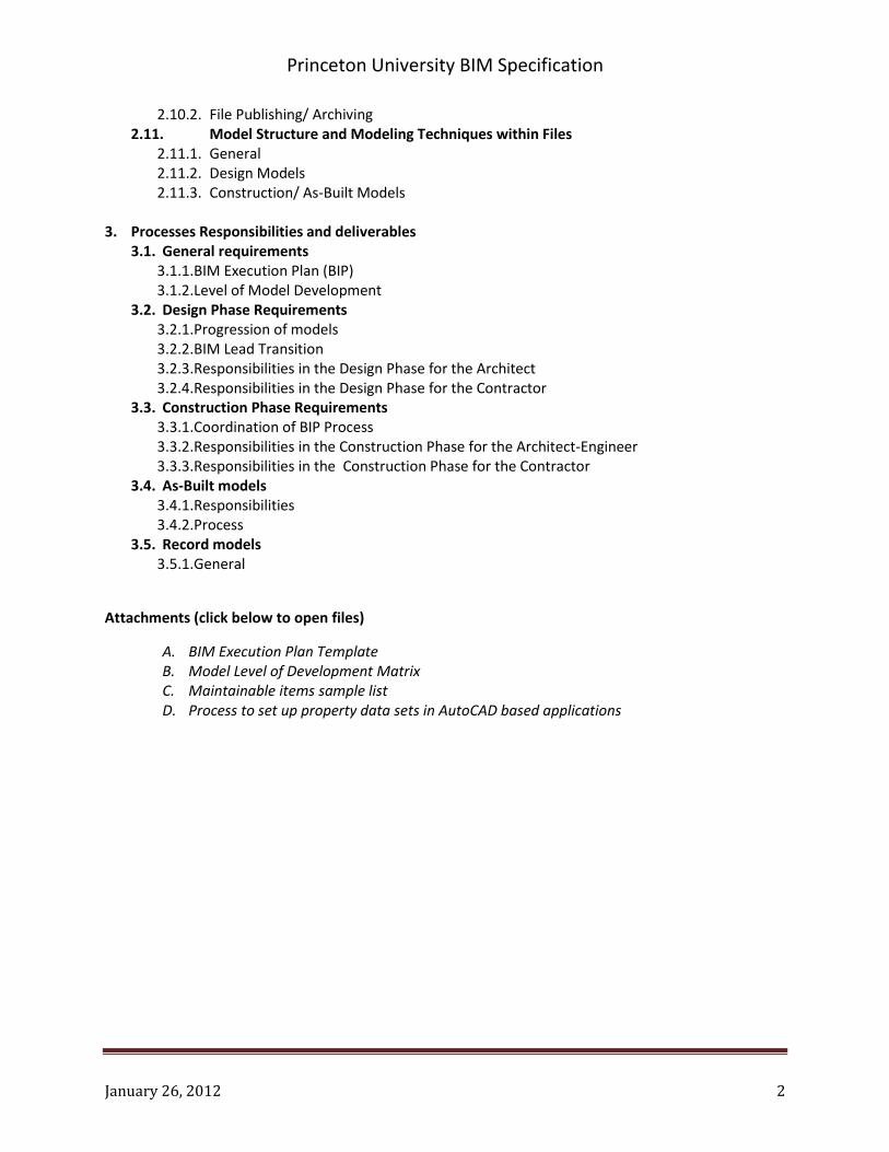
2.10.2. File Publishing/ Archiving 2.11. Model Structure and Modeling Techniques within Files
2.11.1. General 2.11.2. Design Models 2.11.3. Construction/ As-Built Models
3. Processes Responsibilities and deliverables
3.1. General requirements 3.1.1. BIM Execution Plan (BIP) 3.1.2. Level of Model Development
3.2. Design Phase Requirements 3.2.1. Progression of models 3.2.2. BIM Lead Transition 3.2.3. Responsibilities in the Design Phase for the Architect 3.2.4. Responsibilities in the Design Phase for the Contractor
3.3. Construction Phase Requirements 3.3.1. Coordination of BIP Process 3.3.2. Responsibilities in the Construction Phase for the Architect-Engineer 3.3.3. Responsibilities in the Construction Phase for the Contractor
3.4. As-Built models 3.4.1. Responsibilities 3.4.2. Process
3.5. Record models 3.5.1. General
Attachments (click below to open files)
A. BIM Execution Plan Template B. Model Level of Development Matrix C. Maintainable items sample list D. Process to set up property data sets in AutoCAD based applications

Princeton University BIM Specification
January 26, 2012 3
1. Introduction
1.1. BIM Goals: In promoting the use of building information modeling (BIM) 3D technology,
Princeton University will continue to achieve the highest quality building design, enabling
measurable improvements to the design and construction of capital projects resulting in higher
quality building projects and savings in cost and time.
1.1.1. Visualization: The Design Model will, by way of its capacity to provide enhanced 3D
visualization and analysis, improve the Project Team’s effectiveness in sharing the
concept-level design with clients including the Princeton University development office,
program clients, and other stakeholders. As the design progresses BIM will enhance the
Project Team’s ability to visualize the design, prove the design concept, and cooperatively
coordinate building systems. This will provide increased confidence in the coordination of
major structural, architectural and MEP systems. The Design Model may also support
sustainability studies such as energy modeling, day lighting and sun shade analysis.
1.1.2. Collaboration: The Contractor’s involvement during the development of the design will
provide for constructability insight related to sequencing and physical coordination of the
project. BIM may also be used to facilitate order of magnitude quantity take-offs, site
logistics studies, 4D scheduling and general coordination reviews. Periodic web-based
design review sessions will be used to share progress as the design evolves into the
construction phase.
1.1.3. Construction Coordination/ Facilities Management: The Design Model will be used as a
reference document and will establish the format for the Construction Model. During the
construction phase the Contractor will replace the structural, mechanical, electrical and
other selected systems in the Design Model with a fully integrated, coordinated
Construction Model that will serve as Princeton University’s As-Built Model. This As-Built
Model will be embedded with maintainable building components. A specific list of
maintainable items to be embedded in, or linked through the model will be established on
a project by project basis by Princeton University.
1.2. Intent of BIM Specification: This BIM Specification includes the requirements for all projects
utilizing BIM, but also provides a framework to determine project specific BIM goals, processes
and protocols. The BIM Execution Plan Template and BIM Level of Development Matrix,
included as attachments, are principal tools to be utilized by Project Teams to plan the use of
BIM. BIM, along with other collaborative tools, is intended to promote integrated, efficient
design without prescribing burdensome requirements that may diminish the final building
project quality.

Princeton University BIM Specification
January 26, 2012 4
1.2.1. Risk Reduction: While increasing collaboration and value, BIM also will reduce risk to the
Project Team by:
1.2.1.1. Increasing visualization which will reduce Princeton University-generated
changes.
1.2.1.2. Improving design coordination by using 3D technology to generate construction
documents.
1.2.1.3. Increasing contractor confidence through improved visualization and building
coordination.
1.2.1.4. Reducing coordination-related change orders in the construction phase.
1.2.1.5. Promoting pre-fabrication of material assemblies during construction which
reduces field labor and cost.
1.2.1.6. Providing Princeton University with an intelligent as-built model to streamline
the project turnover process and promote improved start up and facility
management.
1.3. Unique nature of projects: Princeton University recognizes that each project type brings unique
challenges and many possible solutions for building design and construction, and encourages
each team to use these guidelines to establish the highest and best use of the technology as it
relates to the specific project type. In addition to these guidelines, Project Teams will utilize a
project-level BIM Execution Plan (BEP) template for documenting the planned use of BIM,
including processes, roles and responsibilities and other protocols for the project duration.
1.4. Qualities of Project Team: Princeton University recognizes BIM as an emerging tool and
encourages Project Team to share the range and depth of their experience during the BIM
implementation planning stage to increase value. For example, the Architect/ Engineer may
have unique office standards and approaches that may prove valuable for a specific project, yet
may not be called out as a requirement. The Project Team is encouraged to include such ideas
in the planning stages so the project may benefit through these synergies.
1.5. Design Standards: The Princeton University Design Standards are the governing document with
respect to design and construction deliverables. This BIM Specification is to be used in
conjunction with the Design Standards, and is not intended to replace or supersede the Design
Standards or other contractual documents.
1.6. Definitions
Concept Definition
As-Built Model The As-Built Model constitutes actual as-built conditions as installed. The As-Built Model also contains additional data such as equipment property data and hyperlinks to related documents.

Princeton University BIM Specification
January 26, 2012 5
BIM Lead Individual representing Project Team member serving as the point of contact for organizational and administrative matters pertaining to BIM Model. Individual will have experience and authority necessary to efficiently manage project responsibilities pertaining to BIM.
Component Model A specific Design Model or Construction Model that is created by a project participant and represents the building system discipline(s) that the project participant is responsible for with respect to providing design or submittal related information. (i.e. lab casework, curtain wall, HVAC piping, etc.)
Construction Model A model or entirety of models created by the Contractor or subcontractor that represents design intent and the physical relationship of building system and from which submittals, shop drawings and as-built documents are derived.
Design Model A model or entirety of models created by the Project Team that represents the design intent and from which the design drawings are derived.
Federated Model A compilation of Component Models in a model review tool in which the individual Component Models are overlaid and at the same time are distinct from each other.
Governing Contract The agreement between Princeton University and the particular Project Team member that governs Princeton’s relationship with that Project Team Member for the relevant Project.
Model Any model created by the BIM software, including, without limitation, an As-Built Model, a Component Model, a Construction Model, a Design Model, a Federated Model, or a Record Model.
Model Author The Project Team Member who created a Model
Princeton University Property Data Set:
Custom data set defined in AutoCAD MEP or other AutoCAD-based applications that can handle object data for additional element specific property data. A baseline version of the dataset includes fields for Room Number, System and Tag. The detailed steps for setting up Property Data Sets in AutoCAD MEP are included in Attachment XX
Project Team Project participants consisting of Architect, sub-consultants, Contractor, sub-contractors and Princeton University representatives.
Record Model:
The Record Model is the entirety of component models that represent the final design, including construction phase design revisions and other drawing revisions. The Record Model is provided to Princeton University at Project Completion.
2. Requirements
2.1. General: This section covers requirements and processes that will be utilized throughout
project and apply to this section and subsequent BIM Specification sections and attachments.

Princeton University BIM Specification
January 26, 2012 6
2.1.1. Early use of BIM: Project Teams will consider the use of models early in the design process
to promote simple, rapid creation of options which can be easily manipulated for
collaborative reviews and workshops with Princeton University. These workshops are
outlined in the Design Standards and include sessions such as conceptual design reviews,
sustainability charrettes and life cycle cost analyses.
2.2. BIM Requirements/ Deviations: Any deviation from this BIM Specification requires the written
approval of Princeton University.
2.3. Controlling Documents
2.3.1. Two-Dimensional Documents Control: The BIM model is to be used solely as a reference
for visualization and to achieve other goals outlined in this specification. The two-
dimensional (2D) documents generated by the design team (including, without limitation,
construction drawings and plans, shop drawings, submittals, and the like), shall be the
operative and controlling documents for the Project. In the case of any conflict between
the 2D documents and the BIM Model, the information and data contained in 2D
documentation shall take precedence over the three-dimensional (3D) BIM model.
2.3.2. Drawings to be Consistent with Model: All drawings created on the project, including ,
without limitation, design drawings, ASI’s, shop drawings, sketches for RFI responses shall
be consistent with the Design or Construction Model to the greatest extent possible. It is
the responsibility of the author of a drawing to ensure that the drawing is consistent with
the information represented in the corresponding Model. The Model Author’s legal
liability shall be determined by the content of the 2D drawings, not by the content of the
3D BIM Model.
2.3.3. Use of the Model to Determine Quantities: It is the responsibility of the Contractor or
subcontractor to determine the appropriateness of any BIM Model for establishing
quantities. In accordance with Section 2.3.1 above, the content of 2D drawings shall
control any quantity determination by a Contractor or subcontractor. The authoring
Project Team member is not responsible for any outcomes of uses of a model by other
Project Team members.
2.4. BIM Models and Responsibilities: As part of their respective responsibilities under their
Governing Contract, Princeton’s Design Standards, and this BIM Specification, each Project
Team member shall have specific responsibilities with respect to the use of BIM on the Project.
The following is an overview of BIM- related roles and responsibilities, which will be more fully
described in the BIM Execution Plan (BEP).
2.4.1. BIM Execution Plan: The Project Team will submit the BEP within 30 days of contract
execution. The architect shall be primarily responsible for coordinating and submitting the

Princeton University BIM Specification
January 26, 2012 7
BEP, and other Project Team members shall cooperate fully with the architect to ensure
the timely completion and submission of the BEP.
2.4.2. Model Progress: Progress of the BIM model and related documentation will be measured
to align with milestones established in the BIP.
2.4.3. Sharing of Models: At appropriate points during the creation of the BIM Model, or as set
forth in the BEP, each Model Author shall share respective model(s) with other Project
Team members.
2.4.4. As-Built Model: Princeton University recognizes the complementary nature of the Design
and Construction Models that are created during the Project and that, at the end of the
project, components from both models will be compiled into an As-Built Model. For
example, the architectural design model may be used as background for individual trade
Component Models as part of the Construction Model, and eventually the As-Built Model
2.4.5. Design Model Roles and Responsibilities: Unless otherwise specified in the BEP, the
architect shall be responsible for the creation, coordination and delivery of the design
documents and BIM Design Model.
2.4.5.1. Coordination: The architect will create the architectural model, and lead the
coordination and establishment of protocols related to sub-consultant Component
Models such as structural, mechanical, fire protection, and furniture. Sub-
consultants will be sole authors of respective Component Models. The architect will
lead process to create a Federated Model.
2.4.5.2. Record Model: During the construction phase the Architect-Engineer will make
model revisions necessary to issue bulletins, answer requests for information (RFI’s)
and issue 2D drawings in connection with design intent or clarifications. The final
copy of Record Model, in addition to final documentation outlined in Design
Standards, will be turned over to Princeton University at project completion.
2.4.5.3. Constructability: During the design phases Contractor and Princeton University
will participate in periodic reviews of Federated Model to assure alignment with
project goals and to promote efficient constructability of the work
2.4.5.4. Protocols: Protocols, processes and procedures shall be established by the
architect as part of the BEP to promote organized information exchange, file safety
and posting of individual and Federated Models for view by Project Team.
Periodically, but no less than monthly, the Design Model will be posted for view by
Princeton University, and any other Project Team member designated by Princeton
University.

Princeton University BIM Specification
January 26, 2012 8
2.4.6. Construction Model Roles and Responsibilities: The Contractor will assume lead
responsibilities for the Construction Model. Accordingly the Contractor will assume the
lead role in to integrate construction phase BIM processes and protocols into the BIM
Execution Plan. The Project Team will continue to contribute to the construction phase
BEP.
2.4.6.1. Architectural Framework for Construction Model: The Architect-Engineer will
provide the Design Models necessary as a reference to enable the Contractor,
including respective sub-contractors, to build individual trade Component Models
(Construction Models). The Design Models will be provided in their latest version
throughout the design and construction process, according to the schedule set forth
in the BEP.
2.4.6.2. Coordination: The Contractor will lead and coordinate the creation of sub-
contractor trade Component Models and will establish protocols related to creation,
review and management of Component Models. The Contractor will lead process to
create a construction phase Federated Model.
2.4.6.3. As-Built Model: During the construction phase the Contractor will make
revisions necessary in the Construction Model to reflect as-built conditions.
Attributes, property sets, tagging and other facility management-related
information, as outlined in this Specification and in the BEP, are considered part of
these requirements. Update of Construction Model will occur concurrently with
construction progress and will be validated at periodic meetings with Princeton
University.
2.4.6.4. Protocols: Protocols, processes and procedures will be established by
Contractor as part of the BEP to promote organized information exchange, file safety
and posting of individual and Federated Models for view by Project Team.
Periodically, but no less than monthly, the Construction Model will be posted for
view by Princeton University.
2.5. File Sharing Platform:
2.5.1. General: The File Sharing Platform must:
2.5.1.1. be able to handle files up to 500MB,
2.5.1.2. support user administration, including component model author tracking,
2.5.1.3. contain an archive of versions and revisions of the relevant models and
documents,
2.5.1.4. provide appropriate email-notification to support efficient workflows,

Princeton University BIM Specification
January 26, 2012 9
2.5.1.5. be secure and only allow authorized and authenticated users access to the
project on the platform.
2.5.2. Design Model: The Architect-Engineer shall provide a file sharing platform for hosting
Design Models and internal communication among the Project Team.
2.5.3. Construction Model: The Contractor shall provide a file sharing platform for hosting
Construction Models and communication with subcontractors.
2.6. Software: The tools listed in Table 1 are required for the respective models. Deviations shall be
approved in writing by Princeton University.
2.6.1. Version: Software used by the Project Team shall be in the most current version yet allow
for a stable environment that is conducive to efficient use of BIM and project delivery.
Individual project participants must coordinate version change with respective BIM lead.
On the project the following systems are required:
Discipline Type of Model
BIM Authoring Tool
Architectural Design
Design Model Autodesk Revit Architecture
Structural Design Design Model Autodesk Revit Structure or Tekla
MEP FP Design Design Model Autocad MEP or Autodesk Revit MEP
Civil Design Design Model AutoCAD Civil 3D
Other Design Model Autodesk Revit Tool (any) or in exceptional cases to be coordinated with Princeton University
Building Systems (e.g. MEP, FP, data, security etc.)
Construction Model
Tool of choice of project participant;
Specific Requirements for Building Systems Models shall be met*.
Other Construction Models
Construction Model
Tool of choice of project participant; Specific Requirements for Other Construction Models shall be met**
*Specific requirements for tools for Building Systems Construction Models:
Export of model to *.dwg file format
Definition of customized data sets (see Attachment D for instructions/
details)

Princeton University BIM Specification
January 26, 2012 10
Geometrical data and customized object property data (data sets) need
to be transported to Navisworks without data loss.
**Specific Requirements for Other Construction Models
Export of model to *.dwg file format
Geometrical data needs to be transported to Navisworks without data
loss.
2.7. Scale, Datum, Horizontal and Vertical References:
2.7.1. Datum: All objects in models are to be modeled at true scale and at true elevation above
sea level in accordance with the datum to be provided by Princeton University.
2.7.2. Definitions: For the purpose of specifying horizontal locations and orientations of objects
in models and drawings the following definitions apply. :
2.7.2.1. True North: Orientation of objects in a model or a drawing in accordance
with the geographical North orientation. Locations have the correct coordinates in
accordance with the state plane coordinate system of New Jersey.
2.7.2.2. Project North: Objects in a model are oriented for convenience of the
modeling and drafting process. Project North is one defined orientation and location
of the building defined by the Architect-Engineer and followed by all project
participants.
2.7.3. Project North: All models and documents shall follow the Project North orientation and
location.
2.7.4. Coordination between models: To ensure alignment and coordination between
Component Models, and between Design Models and Construction Models (DWG files),
the Architect-Engineer shall provide:
2.7.4.1. Gridlines of the project in the Project North coordinate system in *.dwg
AutoCAD file format.
2.7.4.2. Elevation lines of floors (top of finished floor elevation) in *.dwg AutoCAD file
format.
2.8. File Structure: Project Team shall establish file size protocol in BEP.

Princeton University BIM Specification
January 26, 2012 11
2.8.1. Design Models: Design Model files shall be kept at reasonable sizes so that project
participants with typical computing equipment are able to open and review the models. If
files become too large for some project participants to handle or use, the models must be
reduced in size (e.g. split) so that practical file sizes are attained. The actual size of a file is
only one indicator as to whether a file is too large. Some files of moderate size, but with
difficult object structures represented in the file, may also need to be split for acceptable
system operation. For Revit files then recommended file size limit is 200MB for 64 Bit
workstations.
2.8.2. Construction Models: Based on input from Project Team, The Contractor will facilitate,
define and document a file structure for Construction Model files in the BEP. File size shall
be managed so that project participants accessing model can work with the model if they
utilize workstations typical for BIM work. If sizes are too big for acceptable performance
on project participants’ computer systems, the files must be split so that acceptable
system operation is achieved. The following limits are recommended; a. pure AutoCAD
files: 50MB, AutoCAD Extension-based files (e.g. Quickpen, CAD duct: 10MB.
2.9. File Naming:
2.9.1. General: Files will be named in a manner that is descriptive of the content of the file, the
authoring party, version and date. The detailed nomenclature for files will be confirmed
the Project Team in the BEP. Files shall be saved to the latest version of the respective
software. Files shall be named so that the filename contains the following information:
2.9.1.1. Project name
2.9.1.2. Authoring party
2.9.1.3. Phase of the project
2.9.1.4. Discipline or trade represented in the file
2.9.1.5. Level in the building represented in the file (if applicable)
2.9.1.6. Zone/Area in the building represented in the file (e.g. North Wing or South
Wing) (if applicable)
2.9.1.7. Version Number of the file (running number in an iterative modeling process)
2.9.1.8. Data Date when the file was published for the use of the team
2.9.2. Example: 2.9.2.1. Design Model Revit File: SMITH HALL_JONES ARCH_DES_ARC-CS_V0005_2011-
02-22.rvt 2.9.2.1.1. Project = SMITH HALL 2.9.2.1.2. Authoring Party = JONES ARCH - Jones Architects 2.9.2.1.3. Phase of the Project = DES - Design Phase 2.9.2.1.4. Discipline = ARC-CS – Core and Shell Architecture 2.9.2.1.5. Version = V0005 2.9.2.1.6. Data Date = 2011-02-22

Princeton University BIM Specification
January 26, 2012 12
2.9.2.2. Construction Model Revit File:
2.9.2.2.1. SMITH HALL_JSM_CON_DUCT_L02_ZA_V0007_2011-02-22.dwg 2.9.2.2.2. Project = SMITH HALL 2.9.2.2.3. Authoring Party = JSM – Jones Sheet Metal Co. 2.9.2.2.4. Phase of the Project = CON – Construction Phase 2.9.2.2.5. Discipline = DUCT – Ductwork 2.9.2.2.6. Level = L02 – Level 2 2.9.2.2.7. Zone = ZA – Zone A 2.9.2.2.8. Version = V0007 2.9.2.2.9. Data Date = 2011-02-22
2.10. File formats:
2.10.1. Table 2.10.1: The following file formats will be made available to the Project Team.
Model File Formats
Design Model Autodesk Revit File format *.rvt and Export of 3D model to AutoCAD *-3D .dwg file format.
Construction Model of the building systems trades (e.g. mechanical, electrical, plumbing, ductwork, controls, Fire Protection etc.)
*.dwg file format with object property data sets, see attachment D
Construction Model other trades AutoCAD *.dwg file format
Record Model Component Models in the native file format in which the model was created, and in AutoCAD *.dwg file format.
As-Built Model Component Models in the native file format in which the model was created, and in AutoCAD *.dwg file format.
2.10.2. File Publishing/ Archiving: During all project phases, the Architect/Engineer or
Contractor shall archive and make all versions of published files of respective Models
accessible to the Project Team.
2.11. Model Structure and Modeling Techniques within Files
2.11.1. General: Project Team shall confirm and document Model structure and techniques in
BEP.
2.11.1.1. Duplication: No duplication of objects between models. Unintended
duplications of objects shall be removed from models.
Princeton University BIM Specification
January 26, 2012 13
2.11.1.2. Objects: Dedicated, classified, named building objects shall be used whenever
possible to express design intent rather than generic geometrical forms. For
example, use ready-made objects of object families that promote the ability to
search by object attributes.
2.11.1.3. Conflicts: Within one model no two objects shall be depicted in the same space
or in conflict with each other. (e.g., column object and slab object intersecting).
Exceptions: conditions that don’t need to be coordinate such as drywall
penetrations.
2.11.1.4. Cleanup of models: Component Models shall only include content as defined in
the BEP. Objects from other trades and objects outside the intended purpose of the
model (e.g. objects “parked” outside the building for future integration into the
model) shall be removed prior to publishing models.
2.11.1.5. Links: External links shall be removed prior to publishing models.
2.11.2. Design Models
2.11.2.1. Depiction of space: Space: Room, zone and space objects shall be represented
in the architectural model. Room and space objects shall reach to the face of the
confining walls.
2.11.3. Construction Models/ As-Built Models
2.11.3.1. Layers: The layer structure (*.dwg files) shall follow the structure outlined in the
BEP. The layer names for Construction Models shall be submitted to Princeton
University for approval.
2.11.4. Ownership and Use of Models: Use of the Models is subject to clauses G2 and I4 of the
General Terms and Conditions for All Construction Contracts and Articles XII(g) and XIII of
the Architect/Engineer Design Services Contract.
3. Processes Responsibilities and deliverables
3.1. General requirements
3.1.1. BIM Execution Plan (BEP): The BIM Execution Plan, which is generally outlined here and
described in detail in the BIM Execution Plan template (attachment A), is a working tool to
be utilized by the Project Team continuously as the project evolves. The BEP template
provides a working framework to enable the Project Team to develop a customized plan
for attaining BIM goals unique to the project. The BEP shall define BIM goals, information
exchange protocols, file naming, schedule for BIM meetings, BIM Leads, and establish a

Princeton University BIM Specification
January 26, 2012 14
process for tracking progress for BIM related tasks. BEP will include requirements for
project-specific BIM scope as identified in project request-for-proposal (RFP) such as laser
scanning and digital terrain models. At project inception, the Project Team, led by the
architect, will establish the BEP and submit to Princeton University for approval. The
Contractor will lead the BIM efforts as the project transitions to construction phase,
including additions and refinements to the BEP. The BEP will be revised as the project
progresses to capture emerging goals, develop model requirements and establish model-
management protocols.
3.1.1.1. Communication: As defined in BEP, Project team will engage in BIM workshops
and meetings to track progress towards completion.
3.1.2. Level of Model Development: Attachment B – Model Level of Development Matrix defines
model content for each phase of the project. The matrix includes minimum model content
and provides an area to document content that the project team determines to be
required that may be unique to the project goals. The Model Level of Development
Matrix shall be reviewed periodically, but at least monthly, to confirm alignment with BEP
3.2. Design Phase Requirements
3.2.1. Progression of Models: In early design phases simplistic models with limited level of detail,
shall be created. As the design progresses the existing limited detail components shall be
replaced with more detailed components. The level of detail represented in the model
shall correspond with level BEP and Model Level of Development Matrix.
3.2.2. BIM Lead Transition: Project Team is encouraged to establish a timeframe for the
planning and development the construction phase aspects of the BEP activities. Project
Team shall begin work on construction phase BEP as early in the design phase as is
practicable, but planning for the construction phase BIP will begin no later than 50%
construction drawing milestone. This will enable construction phase BIP and
subcontractor responsibilities to be coordinated at the time of 85% drawing completion,
and well before bidding begins.
3.2.3. Responsibilities in the Design Phase for the Architect-Engineer include but are not limited
to:
3.2.3.1. BEP: Leading BEP kickoff meetings, workshops and BEP documentation process.
3.2.3.2. Coordination: Implementation of a model-based design coordination process,
which includes identification, documentation and resolution of constructability
issues. The coordination process shall be structured, transparent and organized to
promote participation of the Project Team

Princeton University BIM Specification
January 26, 2012 15
3.2.3.3. Quantities: Coordinating modeling techniques and strategies with the Project
Team to achieve a high level of utility of design models for the process of extracting
quantity information from models.
3.2.3.4. Maintainable Items: To enable the post-project-completion use of the As-Built
Model for building maintenance by Princeton University a list of maintainable items
will be provided by Princeton University to the Project Team, for use in assembling
and linking building element information, such as operations and maintenance
manuals and warrantee information, to the As-Built Model. Sample Maintainable
Items List is shown in Attachment C. Architect-Engineer will insert unique tags in
Design Model to enable elements to be tracked and related information to be linked
during future project phases.
3.2.3.5. Areas, zones: Project Team will engage in BIM workshop at project inception
(Preliminary Design Phase or Schematic Design Phase) to establish project specific
room names, zones and other attributes to be contained in model, such as
departments, security zones, and other building uses as defined by Princeton
University. These areas and zones will be documented in the BIP and tracked during
project duration, through the construction phase and within the Record and As-Built
Models. The zones shall be represented in the architectural model and exported into
zone definition files.
3.2.3.6. General Organization: Model shall be constructed to enable automatic extraction of
program and other building information and to enable the creation of multiple
options during early design phases.
3.2.4. Responsibilities in the Design Phase for the Contractor include, but are not limited to:
3.2.4.1. Coordination of modeling techniques and strategies within the Project Team
to promote:
3.2.4.1.1. Effective constructability reviews.
3.2.4.1.2. Extraction of quantities of building elements and systems for ease of
evaluation where practical.
3.2.4.2. Color Coding: Utilize color coding of systems and components to effectively
communicate project scope to bidding subcontractors.
3.2.4.3. Procurement strategy: Planning BIM related scope and purchasing of the
appropriate scope from subcontractors for an effective model based coordination
process in accordance with the BIP.

Princeton University BIM Specification
January 26, 2012 16
3.3. Construction Phase Requirements
3.3.1. Coordination of BIP process: Contractor shall schedule required meetings, prepare
updates of BIP for comment and distribute BIM requirements as part of bidding process to
sub-contractors.
3.3.2. Responsibilities in the Construction Phase for the Architect-Engineer include but are not
limited to:
3.3.2.1. Responding to requests by the Contractor to resolve coordination and
constructability issues. The developed solutions shall be represented in the Design
Model and made available to the Contractor for the purpose of validating
constructability and other relevant issues.
3.3.2.2. When issuing design clarifications, changes or responses to RFI’s, the Architect-
Engineer shall generate drawings from the BIM model. The Architect-Engineer
shall take conditions shown in the Construction Model into consideration when
issuing design changes, ASIs and RFI responses.
3.3.2.3. Preparation of Record Models as described in this guideline and in the BIM
Execution Plan.
3.3.3. Responsibilities in the construction phase for Contractor include, but are not limited to:
3.3.3.1. Coordination: Establishing and managing a model-based coordination process
that leads to coordinated Design and Construction Models. This will include:
3.3.3.1.1. Conducting BIM Kick-Off meetings, workshops and BEP updates.
3.3.3.1.2. Conducting trade coordination meetings. These meetings can be held in
person or via web meetings
3.3.3.1.3. Providing actionable feedback and direction to the involved trade contractors
to resolve constructability issues.
3.3.3.1.4. Ensuring technical proficiency of subcontractors to effectively participate in
BIM Model
3.3.3.1.5. Participating in Princeton University tech team review meetings where
Model(s) will be utilized for visualization purposes.
3.3.3.2. As-Built Model: Establishing and maintaining Construction Model to reflect
changes and current conditions. Preparing of As-Built Model(s) .
3.4. As-Built models

Princeton University BIM Specification
January 26, 2012 17
3.4.1. Responsibilities: The Contractor shall produce accurate As-Built Models as described in
the BIM Specification. The Contractor may delegate part of the process of creating As-
Built models to subcontractors but remains responsible for quality control of the model
and deliverables.
3.4.2. Process: The Contractor will insert data fields or link to external data or digital
documentation to provide for unique building element tags and building system or
component identification.
3.4.2.1. Layers: Area/ zone definition layers, created by Architect-Engineer during the
design phase, shall remain in Construction and As-Built Model.
3.4.2.2. Princeton University Property Sets: To enable use of the As-Built model for
facilities data tracking, Contractor shall insert Princeton University property sets in
Component Model(s) as described in Attachment D, Process to set up property data
sets in AutoCad based applications. Property sets shall identify tag number, system
type and other relevant Princeton University facilities information. Data shall be
input into model, or linked from model to Princeton University external data base, or
other location and format determined by Princeton University.
3.4.2.3. Building element data/ information: Contractor will insert relevant building
element data such as model number, serial number, electrical requirements, etc. as
outlined in maintainable items sample list attached as attachment XX. Project
specific list will be provided, with Project Team support, for use during construction
phase.
3.4.2.4. Tagging: Contractor will link tagged building element to final submittal and
operational information archived in Princeton University’s collaborative system
(PCS).
3.4.2.5. Submission: Once completed, the Contractor shall upload the model(s) for
approval by Princeton University.
3.5. Record models:
3.5.1. General: In addition to record CAD files and other documentation required in Design
Standards, Architect-Engineer shall submit copy of Record Model.
Attachments A. BIM Execution Plan Template

Princeton University BIM Specification
January 26, 2012 18
B. Model Level of Development Matrix
C. Maintainable items sample list
D. Process to set up property data sets in AutoCAD based applications


![Update on MBSE & BIMSEV [Package] Building Information Modeling (BIM) [BIM Source Element View] «source element» PAS 1192-2:2013. Incorporating Corrigendum No.1: Specification for](https://img.pdfslide.net/doc/110x75/5ecdca0869106a0e3c7e9739/update-on-mbse-sev-package-building-information-modeling-bim-bim-source.jpg)