Embed Size (px)
Citation preview

PRINCIPAL STRESSES ACTING ON MATERIALS
In 2D and 3D

The inclined plane has an area of A/cosq; the stress normal to the plane and shear stress along theplane (in the direction of maximum inclination)are;
SIMPLE AXIAL STRESS – 2D
N = F cosq
T = F sinq
snq = F/A
2coscosn
N F
A Aq
qs q
cossin 2
2
T F
A Aq
q q
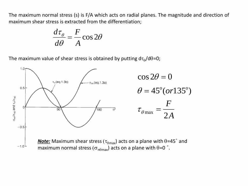
The maximum normal stress (s) is F/A which acts on radial planes. The magnitude and direction ofmaximum shear stress is extracted from the differentiation;
The maximum value of shear stress is obtained by putting dq/dq=0;
Note: Maximum shear stress (qmax) acts on a plane with q=45˚ andmaximum normal stress (snqmax) acts on a plane with q=0 ˚.
cos2d F
d A
q qq
max
cos 2 0
45 ( 135 )
2
or
F
Aq
q
q
o o

Problem
A cylindrical rock sample is subjected to an axial compressive force of 5kN. The diameter of the sample is 50 mm. Please determine;a. Normal stress and shear stress on an inclined plane of 30˚. b. Maximum shear stressc. Inclination of planes on which the shear stress is half of maximum shear stress.
Solution
a. Unit area; A=πr2=1.96x10⁻³ m2
Normal stress; snq = (5 kN/1.96x10-3)cos230 = 1913 kPaShear stress; q= (5 kN/2x1.96x10-3)sin60 = 1105 kPa
b. Maximum Shear stress; qmax= (F/2A) =(5 kN/2x1.96x10-3) = 1275 kPa
c. Maximum Shear stress; 1/2qmax= qmax sin2q; q=15˚ or 75˚
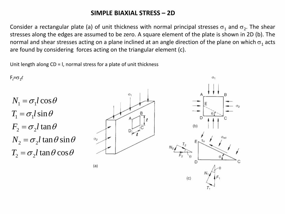
SIMPLE BIAXIAL STRESS – 2D
Consider a rectangular plate (a) of unit thickness with normal principal stresses s1 and s2. The shearstresses along the edges are assumed to be zero. A square element of the plate is shown in 2D (b). Thenormal and shear stresses acting on a plane inclined at an angle direction of the plane on which s1 actsare found by considering forces acting on the triangular element (c).
Unit length along CD = l, normal stress for a plate of unit thickness
Fl=s1l
1 1
1 1
2 2
2 2
2 2
cos
sin
tan
tan sin
tan cos
N l
T l
F l
N l
T l
s q
s q
s q
s q q
s q q

1 2secn l N Nqs q
2 2
1 2cos sinnqs s q s q
Forces in normal stress direction
Forces in shear stress direction;
1 2 / secT T q q
1 2
1( )sin 2
2q s s q
max 1 2
1( )
2q s s
1max 1 2( )
2ifq
s s s
Maximum shear stress on 45˚ plane;
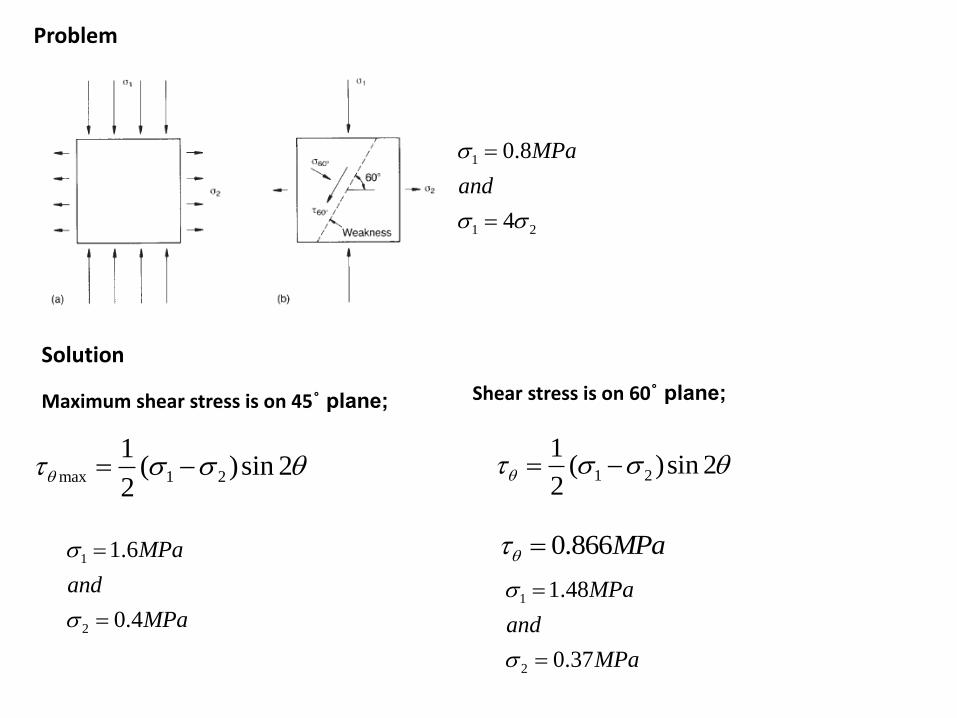
Problem
Solution
1
1 2
0.8
4
MPa
and
s
s s
max 1 2
1( )sin 2
2q s s q
Maximum shear stress is on 45˚ plane;
1
2
1.6
0.4
MPa
and
MPa
s
s
Shear stress is on 60˚ plane;
1 2
1( )sin 2
2q s s q
0.866MPaq
1
2
1.48
0.37
MPa
and
MPa
s
s

2
2
1 cos 2cos
2
1 cos 2sin
2
1 1( ) ( )cos2 sin 2
2 2n z y z y zyqs s s s s q q
2 2
2 21 1( ) ( )
2 2n z y z y zyq qs s s s s
2 2sin 2 cos 2 1q q
2 2 2
1( )
2
1( )
2
z y
z y zy
s
and
r
s s
s s
( 2 2 2
n s rq qs
Which is the equation of a circle with radius “r” and with a center on “-s” plot
MOHR STRESS CIRCLE
The graphical stress relations was discovered by Culmann (1866) and developed by Mohr (1882) based on the equations given below


Biaxial Compression-2DBiaxial stresses are represented by a circle which plots in “+s” space, passing through s1 and s2 on“=0” axis. Centre of circle is on “=0” axis at point “1/2(s1+s2)”.Radius of circle has the magnitudeof “1/2(s1-s2)” which represents “max”
Biaxial Tension-2DThe stress circle extends into both positive and negative “s” space. Center of circle is on “=0” axis at point “1/2(s1+s2)”.Radius is “1/2(s1-s2)=max” which occurs at 45˚ to s1 direction. Normal stress is zero in directions “±q” to the direction of s1;
1 2
1 2
cos2s s
qs s

Biaxial Shear-2D
The stress circle has a radius of “zy” which is opposite to “yz”. Center of the circle is at “s=0; =0”. Principal normal stresses “s1 and s2” are equal but opposite in sign which have magnitudes equal to “zy”. The directions of principal normal stresses are at 45˚ in directions of “zy” and “yz”


General Considerations on Principal Stress Relations

Problem
A plane element is subjected to the stresses given below. Determine the principal stresses and directions by Mohr’s circle.
The principal stresses are represented by points G and H. Since the coordinate of “C” is 40; CD= (402+302)0.5 = 50Minimum principal stress issmin=OG=OG-CG=40-50=-10 Mpa
Maximum principal stress issmax=OH=OC+CH=40+50=90 Mpa
The angle 2qp;tan 2qp =30/40; qp =18.43

STRESS in 3D
In the body of a stressed material, 3D stresses at any point can be represented as if acting on a smallcubical element. The nine stresses in three Cartesian space are in form of a matrix “STRESS TENSOR”