Embed Size (px)
Citation preview
Page 1
Principles of Atoric Lens DesignDarryl Meister, ABOM Lens TalkSOLA Technical Marketing Vol. 27, No. 03 (Jan. 1998)
BACKGROUND
Industry studies have shown that approximately70% of all spectacle wearers receive a cylindercorrection for astigmatism. Further, 50% of thesewearers have corrections with over 0.50 D ofcylinder power. This article will show thatconventional lens design does not adequatelyaddress the peripheral optical performance oflenses with cylinder power. Moreover, it willexplain how new ‘atoric’ lens designs can providesuperior optical performance for all patients—including those with astigmatism.
IN REVIEW
Our discussion of ‘atoricity’ expands upon theprinciples and concepts that appeared in an earlierissue of Lens Talk (July 1998). Before continuing, weshould review a few key points from this previousarticle:
• Spectacle lenses suffer from various ‘lensaberrations’ that affect the quality of peripheralvision afforded by the lens. Optical performancecan be improved by reducing these aberrations,or ‘optimizing’ the lens.
• Lenses produced with optimum spherical frontbase curves are often referred to as ‘best formlenses,’ since these lenses reduce the lensaberrations that can blur peripheral vision.Today, most manufacturers provide best formlenses.
• Early lenses employed spherical curves simplybecause these were relatively easy to produce inglass using simple tools. With the advent of high-speed computing, plastic lens casting, andnumerically-controlled grinding techniques, lensmanufacturers developed the ability to rapidlyproduce more sophisticated lens surfaces likeaspherics.
• Although steeper best form lenses provideexcellent peripheral vision, they can be relativelythick, heavy, and bulbous. To answer the needfor thinner, lighter, and flatter lenses that stillmaintained excellent optical performance,manufacturers began to use aspheric surfaces on
spectacle lenses—often in conjunction withhigher-index materials.
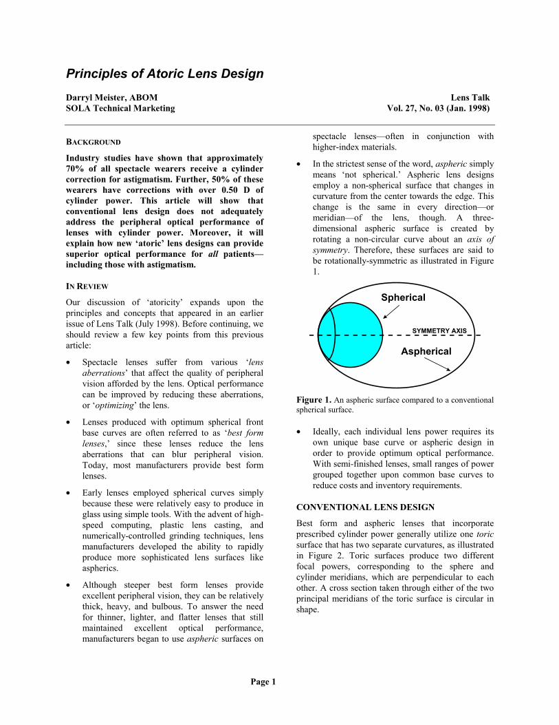
• In the strictest sense of the word, aspheric simplymeans ‘not spherical.’ Aspheric lens designsemploy a non-spherical surface that changes incurvature from the center towards the edge. Thischange is the same in every direction—ormeridian—of the lens, though. A three-dimensional aspheric surface is created byrotating a non-circular curve about an axis ofsymmetry. Therefore, these surfaces are said tobe rotationally-symmetric as illustrated in Figure1.
Spherical
Aspherical
SYMMETRY AXIS
Figure 1. An aspheric surface compared to a conventionalspherical surface.
• Ideally, each individual lens power requires itsown unique base curve or aspheric design inorder to provide optimum optical performance.With semi-finished lenses, small ranges of powergrouped together upon common base curves toreduce costs and inventory requirements.
CONVENTIONAL LENS DESIGN
Best form and aspheric lenses that incorporateprescribed cylinder power generally utilize one toricsurface that has two separate curvatures, as illustratedin Figure 2. Toric surfaces produce two differentfocal powers, corresponding to the sphere andcylinder meridians, which are perpendicular to eachother. A cross section taken through either of the twoprincipal meridians of the toric surface is circular inshape.

Page 2
CylinderMeridian
Curve
SphereMeridian
Curve
Figure 2. Toric surface with circular cross sections.
Sphero-cylindrical lenses that use toric surfaces toproduce cylinder power vary in power between thesphere and cylinder meridians of the lens, as shown inFigures 3 and 4. This is not the case with sphericallenses, which have a constant power around eachmeridian of the lens. Consider the comparison below:
+2.00 sph
+2.00 D
+2.00 D
+2.00 D+2.00 D
+2.00 D
+2.00 D +2.00 D
+2.00 D
Figure 3. This +2.00 D spherical-powered lens has thesame power through every raidal direction (or meridian) ofthe lens.
+2.00 -1.00 × 090
+2.00 D
+1.00 D
+1.50 D+1.50 D
+1.00 D
+1.50 D +1.50 D
+2.00 D
Figure 4. This sphero-cylindrical lens varies in powerfrom meridian to meridian. The 90° meridian contains thesphere power of +2.00 D, and the 180° meridian containsthe combined sphere and cylinder power: +2.00 + -1.00 =+1.00 D.
Because each lens power requires its own lens formto eliminate aberrations, the design of lenses withsphere and cylinder powers cannot be entirelyoptimized using conventional spherical surfaces. Thelens designer may choose the optimum front curvebased upon the sphere meridian, the cylinder
meridian, or the average power (spherical equivalent)of the lens. In lenses with low cylinder power theperformance differences are generally negligible, butin higher cylinder powers the field of clear vision isoften considerably reduced—no matter whichapproach is used. Best form and aspheric lenses withcylinder power could more accurately be described asa ‘best compromise’ lens.
ATORIC LENS DESIGN
Over the past few years, additional advances in lensdesign have provided lens designers with the abilityto produce surfaces even more complex than therotationally-symmetrical aspheric designs describedearlier. By literally varying the amount of asphericityfrom one meridian of the lens to another, an atoricsurface can be produced. Just as aspheric denotes asurface that departs from being completely spherical,‘atoric’ denotes a surface that departs from being anexact circular toric. Figure 5 depicts one possibleatoric surface.
AsphericCylinder
Curve
AsphericSphereCurve
Figure 5. An atoric surface with a differing amount ofasphericity applied to the sphere and cylinder meridians.
Atoricity is an extension of aspheric designtechnology, allowing lens designers to optimize forboth the sphere and cylinder powers of a lens. Thisensures that nearly all wearers enjoy the same widefield of vision, especially those with astigmatism.Atoric lenses consistently outperform either best form(with spherical base curves) or rotationally-symmetrical aspheric lenses across a wide range ofprescriptions.
The atoric lens provides a significantly wider field ofperfectly clear vision, and consistently providesoptical performance superior to conventional lensdesigns over a wide range of lens powers—especiallyhigher cylinder powers. Let’s look at the differences

Page 3
between best form, aspheric, and atoric optimizationstrategies using an actual prescription. Figure 6compares the ‘relative asphericity’ (an abstractcorrection concept used here for illustrative purposes)of three different lens designs for the followingprescription: +2.00 -1.00 × 090.
Spherical Surface
0.0
0.0
0.00.0
0.0
0.0 0.0
0.0
Aspheric Surface
-4.0
-4.0
-4.0-4.0
-4.0
-4.0 -4.0
-4.0
Atoric Surface
-4.0
-1.5
-2.5-2.5
-1.5
-2.5 -2.5
-4.0
Figure 6. Relative asphericity (or correction factors) forspherical, aspheric, and atoric surfaces.
These values more or less represent the relativedeparture of the surface from a perfect circle througheach meridian, and can be thought of as the amount ofasphericity present through that meridian. The furtherthis value departs from 0.0, the more aspheric (ornon-circular) the curvature of the surface is throughthat meridian. We can think of this relative value asthe ‘correction factor’ for now (again, strictly for ourpurposes).
Spherical surface. It has a relative value of 0.0 inevery direction (or meridian)—meaning that it isperfectly spherical in every direction. Therefore, the+2.00 D sphere meridian receives the same correctionfactor of 0.0 as the +1.00 D cylinder meridian does.We know these two powers should be optimizeddifferently, since a +1.00 D power requires a flatterbase curve than a +2.00 D power.
Aspheric surface. It has a relative value of -4.0,indicating the aspheric lens departs significantly fromthe spherical lens in every direction (or meridian).This is what is meant by the phrase ‘rotationally-symmetric’—the lens surface have the same curvaturein every direction, and can be produced by simplyrotating a single curve with the appropriate relativeasphericity about an axis. Again, the aspheric lensprovides only the one correction factor of -4.0through every meridian.
Atoric surface. Note how the relative asphericitychanges from meridian to meridian. The +2.00 Dmeridian has a correction factor of -4.0, while the+1.00 D meridian has a factor of -1.5. In essence,each meridian of the lens has been adjusted with thecorrection factor specifically required for thatparticular power. This ensures that both the sphereand cylinder meridional powers—as well as all of thepowers in between—are properly optimized.
Unfortunately, conventional spectacle lens surfacingequipment was not designed to manufacture theserather complex surfaces. For instance, moderncylinder machines and lap tools—which are used forfining and polishing the generated lens surface—canonly produce spherical and circular toric surfacesbecause of the geometry and motions involved.Although there are systems available that use either a‘cut and coat’ process or a numerically-controlledmilling machine along with flexible-pad polishing,these systems are quite expensive and cost-prohibitivefor most laboratories at this point.
Currently, most atoric lenses are available in either oftwo forms: factory finished stock lenses—which havehad the atoric surface molded at the factory, andcustom-ground semi-finished lenses—which have hadthe atoric surface ground using the equipmentdescribed above (typically also at the factory level).
The atoric design strategies that we’ve discussed sofar are generally applicable to any single vision (oreven multifocal) lens design. Certain manufacturershave begun offering ‘atoric’ progressive additionlenses, but it should be noted that these atoric designsdiffer slightly from the design that we have looked atso far. These designs still optimize for both the sphere

Page 4
and cylinder powers of the lens. In addition, however,these manufactures advertise that their lenses can alsobe optimized for other parameters, like aberrationsproduced by prism or by viewing through the nearzone of the lens obliquely. This additional freedom ispossible since each lens is custom ground (unlikefinished, stock lenses). These surfaces are even morecomplex, or arbitrary, than the atoric surfaces usedfor stock lenses, and each lens has to be individuallydesigned and fabricated using expensive equipment—usually at the factory level. Consequently, such lensesrequire additional shipping time and are considerablymore expensive.
Because of their obvious superiority to conventionallens designs over a wide range of prescriptions, weshould expect to see more atoric single vision andprogressive addition lenses in the future. We can nowlook at some optical performance comparisonsbetween the three lens designs for plus and minussphero-cylindrical prescriptions. All three of the lensdesigns shown in Figure 7 are from the samemanufacturer. The white area within the framerepresents the field of perfectly clear vision, while theshaded area represents the region of reduced opticalquality and potential blur for the wearer.
Figure 7. Comparison of the fields of perfectly clear vision for best form, aspheric, and atoric polycarbonate lens designs. Twoprescriptions are shown. Note that the atoric lens design consistently provides a larger area of clear vision.
Field of Perfectly Clear Vision ComparisonBest Form Poly Aspheric Poly Atoric Poly
Rx:
+4.00 –2.00
Rx:
-6.00 –2.00
![Convex lens Concave lensbh.knu.ac.kr/~ilrhee/lecture/modern/chap6.pdf · 2017-11-13 · Convex lens Concave lens Optical lens 공기중에사용 Diopter [예제] 곡률반경이R](https://img.pdfslide.net/doc/110x75/5f0845f47e708231d4213166/convex-lens-concave-ilrheelecturemodernchap6pdf-2017-11-13-convex-lens-concave.jpg)