Embed Size (px)
Citation preview

© Jones & Bartlett Learning, LLCNOT FOR SALE OR DISTRIBUTION
© Jones & Bartlett Learning, LLCNOT FOR SALE OR DISTRIBUTION
© Jones & Bartlett Learning, LLCNOT FOR SALE OR DISTRIBUTION
© Jones & Bartlett Learning, LLCNOT FOR SALE OR DISTRIBUTION
© Jones & Bartlett Learning, LLCNOT FOR SALE OR DISTRIBUTION
© Jones & Bartlett Learning, LLCNOT FOR SALE OR DISTRIBUTION
© Jones & Bartlett Learning, LLCNOT FOR SALE OR DISTRIBUTION
© Jones & Bartlett Learning, LLCNOT FOR SALE OR DISTRIBUTION
© Jones & Bartlett Learning, LLCNOT FOR SALE OR DISTRIBUTION
© Jones & Bartlett Learning, LLCNOT FOR SALE OR DISTRIBUTION
© Jones & Bartlett Learning, LLCNOT FOR SALE OR DISTRIBUTION
© Jones & Bartlett Learning, LLCNOT FOR SALE OR DISTRIBUTION
© Jones & Bartlett Learning, LLCNOT FOR SALE OR DISTRIBUTION
© Jones & Bartlett Learning, LLCNOT FOR SALE OR DISTRIBUTION
© Jones & Bartlett Learning, LLCNOT FOR SALE OR DISTRIBUTION
© Jones & Bartlett Learning, LLCNOT FOR SALE OR DISTRIBUTION
© Jones & Bartlett Learning, LLCNOT FOR SALE OR DISTRIBUTION
© Jones & Bartlett Learning, LLCNOT FOR SALE OR DISTRIBUTION
© Jones & Bartlett Learning, LLCNOT FOR SALE OR DISTRIBUTION
© Jones & Bartlett Learning, LLCNOT FOR SALE OR DISTRIBUTION
© Th
ep U
rai/S
hutte
rstoc
k
OUTLINEIntroduction to Mechanical VentilationVentilation
Spontaneous BreathingNegative Pressure BreathingPositive Pressure BreathingInvasive Versus Noninvasive Ventilation
Ventilator PrinciplesInput Power and Control SystemsVentilator Variables: Breath TriggerVentilator Variables: Breath CycleOperator InterfaceVentilator Classification or Taxonomy
Ventilator ModesContinuous Mandatory Ventilation Intermittent Mandatory Ventilation Positive End-Expiratory Pressure Continuous Positive Airway Pressure Pressure Support VentilationAirway Pressure Release Ventilation Automatic Tube Compensation Proportional Assist Ventilation Dual Modes and Adaptive ControlHigh-Frequency Ventilation Neurally Adjusted Ventilatory Assist
Ventilator ParametersFlow WaveformsInspiratory PauseFio2
PEEP/CPAPAlarmsHumidificationSigh Breaths
Effects of Mechanical Ventilation on Organ SystemsPulmonary SystemCardiovascular SystemRenal SystemGastrointestinal SystemCentral Nervous System
Complications of Mechanical VentilationPulmonaryExtrapulmonary Organ Systems
OBJECTIVES1. Summarize the history of events that led to modern
mechanical ventilation.2. Contrast the differences between positive and negative
pressure ventilation.3. Recognize differences in patient interface when considering
invasive and noninvasive mechanical ventilation.4. Define the timing points that constitute a breath and
calculate the respiratory rate from TI and TE.5. Describe alveolar and dead space ventilation and calculate
VE and VA.6. Interpret changes in volume, airflow, and alveolar and
intrapleural pressure over the course of a single breath.7. Describe the differences between an iron lung and a chest
cuirass.8. Identify the components of a ventilator circuit and the
mechanical events during lung inflation and deflation during delivery of a positive pressure breath.
9. Describe the effects of alterations in lung mechanics (CST and Raw) on volume and pressure in volume and pressure-control modes.
10. Predict changes in peak inspiratory pressure and plateau pressure when either CST or Raw are altered.
11. Define PEEP and describe its influence on gas exchange and hemodynamics.
12. Describe the variables of interest in an optimal PEEP study.13. Define pressure support ventilation (PSV) and describe its
influence on the work of breathing (WOB).14. Define CPAP, BiPAP, AutoPAP, ASV, CFLEX, EPR, IPAP,
and EPAP.15. Describe patient scenarios that will lead to increased mean
airway and peak inspiratory pressures.16. Describe the variables that can be trigger inspiration during
mechanical ventilation.
Principles of Mechanical Ventilation
Gregory A. Holt, Sheila A Habib, and David C. Shelledy
95
3CHAPTER
9781284139860_CH03_095_154.indd 95 22/02/19 12:03 PM
© Jones & Bartlett Learning, LLC. NOT FOR SALE OR DISTRIBUTION.
© Jones & Bartlett Learning, LLCNOT FOR SALE OR DISTRIBUTION
© Jones & Bartlett Learning, LLCNOT FOR SALE OR DISTRIBUTION
© Jones & Bartlett Learning, LLCNOT FOR SALE OR DISTRIBUTION
© Jones & Bartlett Learning, LLCNOT FOR SALE OR DISTRIBUTION
© Jones & Bartlett Learning, LLCNOT FOR SALE OR DISTRIBUTION
© Jones & Bartlett Learning, LLCNOT FOR SALE OR DISTRIBUTION
© Jones & Bartlett Learning, LLCNOT FOR SALE OR DISTRIBUTION
© Jones & Bartlett Learning, LLCNOT FOR SALE OR DISTRIBUTION
© Jones & Bartlett Learning, LLCNOT FOR SALE OR DISTRIBUTION
© Jones & Bartlett Learning, LLCNOT FOR SALE OR DISTRIBUTION
© Jones & Bartlett Learning, LLCNOT FOR SALE OR DISTRIBUTION
© Jones & Bartlett Learning, LLCNOT FOR SALE OR DISTRIBUTION
© Jones & Bartlett Learning, LLCNOT FOR SALE OR DISTRIBUTION
© Jones & Bartlett Learning, LLCNOT FOR SALE OR DISTRIBUTION
© Jones & Bartlett Learning, LLCNOT FOR SALE OR DISTRIBUTION
© Jones & Bartlett Learning, LLCNOT FOR SALE OR DISTRIBUTION
© Jones & Bartlett Learning, LLCNOT FOR SALE OR DISTRIBUTION
© Jones & Bartlett Learning, LLCNOT FOR SALE OR DISTRIBUTION
© Jones & Bartlett Learning, LLCNOT FOR SALE OR DISTRIBUTION
© Jones & Bartlett Learning, LLCNOT FOR SALE OR DISTRIBUTION
96 CHAPTER 3 Principles of Mechanical Ventilation
17. Describe the variables that can cycle a breath from inspiration to expiration.
18. Contrast the differences between PC-AC and VC-AC.19. Contrast the differences between PC-IMV and VC-IMV.20. Describe the rationale for prone positioning ARDS patients.21. Describe lung protective strategies for mechanical ventilation.22. Define APRV and compare this mode to BiPAP.23. Describe the use of automatic tube compensation (ATC).24. Define PAV and describe its use.25. Identify dual modes of ventilation.26. Define PRVC and VAPS.27. Describe each of the four types of high-frequency ventilation
(HFV).28. Contrast the trigger variable used in NAVA to conventional
mechanical ventilation.29. Describe inspiratory flow waveforms used in mechanical
ventilation.30. Determine the ventilator variables that affect Pao2, pH,
and Paco2.31. Identify the alarms that require clinician adjustment and the
levels of priority assigned.32. Describe the rationale for a sigh breath.33. Explain the effects of positive pressure ventilation
on the lung.34. Explain the effects of positive pressure ventilation on the
cardiac/cardiovascular system.35. Describe the central nervous system (CNS), renal, and
gastrointestinal effects of positive pressure ventilation.36. Explain the importance of appropriate sedation protocols
during weaning from mechanical ventilation.37. Describe the influence of Paco2 on intracranial
pressure (ICP).38. Identify the effects of sleep disruption on the ICU patient.39. List the complications of mechanical ventilation and
explain each.
KEY TERMSacidosisacute lung injury (ALI)acute respiratory distress
syndrome (ARDS)afterloadairway pressure release
ventilation (APRV)airway resistance (Raw)alkalosisalveolar volumeamyotrophic lateral
sclerosis (ALS)assist control (A/C)
atelectotraumaatrial natriuretic
peptide (ANP)automatic positive
airway pressure (autoPAP)
automatic servo ventilation (autoSV)
automatic tube compensation (ATC)
autoPEEPbilevel positive airway
pressure (BiPAP)
breath cyclebreath triggercontinuous positive airway
pressure (CPAP)dead space volume (VD)expiratory positive airway
pressure (EPAP)expiratory time (TE)extrinsic PEEPflow cycleflow-time scalarfraction of inspired
oxygen (Fio2)high-frequency jet
ventilation (HFJV)high-frequency oscillatory
ventilation (HFOV)high-frequency percussive
ventilation (HFPV)high-frequency
positive pressure ventilation (HFPPV)
hyperventilationhypoventilationinspiratory positive airway
pressure (IPAP)inspiratory time (TI)inspiratory to expiratory
ratio (I:E)intracranial pressure (ICP)intrinsic PEEPiron lunglung compliance (CL)mean airway pressure
(MAP)minute alveolar volumeminute ventilation (VE)negative pressure
ventilationneurally adjusted
ventilatory assist (NAVA)noninvasive positive
pressure ventilation (NPPV)
oxygen content in arterial blood (Cao2)
oxygen content in mixed venous blood (CV
–o2)
oxygen delivery (Do2)oxygen saturation in
arterial blood (Sao2)
oxygen saturation in mixed venous blood (Sv
–o2)
partial pressure of alveolar oxygen (Pao2)
partial pressure of arterial oxygen (Pao2)
partial pressure of mixed venous oxygen (Pv
–o2)
peak airway pressure (Paw)peak inspiratory
pressure (PIP)plateau pressure (Pplateau)positive end-expiratory
pressure (PEEP)positive pressure ventilationpreloadpressure control (PC)pressure-regulated volume
control (PRVC)pressure support
ventilation (PSV)pressure–time scalarproportional assist
ventilation (PAV)pulmonary vascular
resistance (PVR)synchronized intermittent
mandatory ventilation (SIMV)
tidal volume (VT)time cyclingtotal cycle time (Ttot)transmural wall pressureventilator-associated
lung injury (VALI)ventilator-associated
pneumonia (VAP)ventilator-induced
lung injury (VILI)ventilator modevolume-assured pressure
support (VAPS)volume control (VC)volume of carbon dioxide
production (VCO2)volume of oxygen
uptake (VO2)volume support (VS)volutraumawork of breathing (WOB)
Introduction to Mechanical VentilationThe development of respiratory care progressed through history from Galen’s observations on the re-spiratory and circulatory systems in the 2nd century to the early 20th century, when great strides in pulmonary physiology were made. The Drinker Respirator, which provided negative pressure ventilation, was introduced in 1928, and a commercial version of this “iron lung”
was offered by John Emerson in 1932. In the 1940s and 1950s, polio epidemics were sweeping across Europe and the United States. Worldwide, 500,000 people per year were either paralyzed or had died from the dis-ease.1 These negative pressure ventilators were some-times employed in large halls dedicated to providing support to polio victims (Figure 3-1). The iron lung did not require an artificial airway and was simple and easy to use. Problems included difficulty with patient access, patient immobility, and large and bulky equipment.
9781284139860_CH03_095_154.indd 96 21/02/19 5:37 PM
© Jones & Bartlett Learning, LLC. NOT FOR SALE OR DISTRIBUTION.

© Jones & Bartlett Learning, LLCNOT FOR SALE OR DISTRIBUTION
© Jones & Bartlett Learning, LLCNOT FOR SALE OR DISTRIBUTION
© Jones & Bartlett Learning, LLCNOT FOR SALE OR DISTRIBUTION
© Jones & Bartlett Learning, LLCNOT FOR SALE OR DISTRIBUTION
© Jones & Bartlett Learning, LLCNOT FOR SALE OR DISTRIBUTION
© Jones & Bartlett Learning, LLCNOT FOR SALE OR DISTRIBUTION
© Jones & Bartlett Learning, LLCNOT FOR SALE OR DISTRIBUTION
© Jones & Bartlett Learning, LLCNOT FOR SALE OR DISTRIBUTION
© Jones & Bartlett Learning, LLCNOT FOR SALE OR DISTRIBUTION
© Jones & Bartlett Learning, LLCNOT FOR SALE OR DISTRIBUTION
© Jones & Bartlett Learning, LLCNOT FOR SALE OR DISTRIBUTION
© Jones & Bartlett Learning, LLCNOT FOR SALE OR DISTRIBUTION
© Jones & Bartlett Learning, LLCNOT FOR SALE OR DISTRIBUTION
© Jones & Bartlett Learning, LLCNOT FOR SALE OR DISTRIBUTION
© Jones & Bartlett Learning, LLCNOT FOR SALE OR DISTRIBUTION
© Jones & Bartlett Learning, LLCNOT FOR SALE OR DISTRIBUTION
© Jones & Bartlett Learning, LLCNOT FOR SALE OR DISTRIBUTION
© Jones & Bartlett Learning, LLCNOT FOR SALE OR DISTRIBUTION
© Jones & Bartlett Learning, LLCNOT FOR SALE OR DISTRIBUTION
© Jones & Bartlett Learning, LLCNOT FOR SALE OR DISTRIBUTION
Introduction to Mechanical Ventilation 97
In 1952, a polio outbreak in Copenhagen (following a 1951 international convention on polio) resulted in 50 new admissions every day and an 87% mortality rate. Medical students were called upon, and nearly 1500 provided manual bag-mask positive pressure ventila-tion totaling 165,000 hours with a drop in mortality to approximately 25%.2 The development of the modern intensive care unit (ICU) providing mechanical ventila-tory support can be traced directly to the impact of this single disease, polio.
The use of positive pressure ventilation grew along a similar timeline and rapidly became the pre-dominant form of ventilatory support in use. Patient- triggered, pressure-cycled ventilators (e.g., Bird respirators) and flow-sensitive breathing valves (e.g., the Bennett valve) based on technology developed dur-ing World War II were further developed in the 1950s and 1960s (Figure 3-2). Volume ventilators began to become available, first as time-triggered devices, and later with patient-triggered options. Space require-ments and patient access were obvious advantages of
FIgURE 3-1 The Iron Lung in Use During the Polio Epidemic.TOP: ©Dennis MacDonald/age fotostock/Alamy Stock Photo; BOTTOM: ©Science History Images/Alamy Stock Photo.
FIgURE 3-2 Bird and Bennett Pressure Respirators. The Bennett PR-2 was time or patient triggered to inspiration, pressure limited, and flow cycled to expiration. The Bird Mark 7 was time or patient triggered to inspiration and pressure cycled to expiration.
these new ventilators over the “iron lung.” The volume ventilators of the 1960s and early 1970s allowed cli-nicians to set a precise tidal volume (VT) and backup respiratory rate to guarantee a minimum minute venti-lation. It took longer to understand the mechanisms of ventilator-induced lung injury and the balance between atelectasis, pulmonary overdistension, and barotrauma. The mechanisms of ventilator-induced lung injury (VILI) are due, in part, to the release of cellular inflammatory mediators associated with the use of large tidal volumes and pressures. This has led to a reduction in applied tidal volumes from 10 to 15 mL/kg used since the mid-1970s to the 4 to 8 mL/kg currently employed.3,4 Additional methods to reduce ventilator-associated lung injury include appropriate application
9781284139860_CH03_095_154.indd 97 21/02/19 5:37 PM
© Jones & Bartlett Learning, LLC. NOT FOR SALE OR DISTRIBUTION.

© Jones & Bartlett Learning, LLCNOT FOR SALE OR DISTRIBUTION
© Jones & Bartlett Learning, LLCNOT FOR SALE OR DISTRIBUTION
© Jones & Bartlett Learning, LLCNOT FOR SALE OR DISTRIBUTION
© Jones & Bartlett Learning, LLCNOT FOR SALE OR DISTRIBUTION
© Jones & Bartlett Learning, LLCNOT FOR SALE OR DISTRIBUTION
© Jones & Bartlett Learning, LLCNOT FOR SALE OR DISTRIBUTION
© Jones & Bartlett Learning, LLCNOT FOR SALE OR DISTRIBUTION
© Jones & Bartlett Learning, LLCNOT FOR SALE OR DISTRIBUTION
© Jones & Bartlett Learning, LLCNOT FOR SALE OR DISTRIBUTION
© Jones & Bartlett Learning, LLCNOT FOR SALE OR DISTRIBUTION
© Jones & Bartlett Learning, LLCNOT FOR SALE OR DISTRIBUTION
© Jones & Bartlett Learning, LLCNOT FOR SALE OR DISTRIBUTION
© Jones & Bartlett Learning, LLCNOT FOR SALE OR DISTRIBUTION
© Jones & Bartlett Learning, LLCNOT FOR SALE OR DISTRIBUTION
© Jones & Bartlett Learning, LLCNOT FOR SALE OR DISTRIBUTION
© Jones & Bartlett Learning, LLCNOT FOR SALE OR DISTRIBUTION
© Jones & Bartlett Learning, LLCNOT FOR SALE OR DISTRIBUTION
© Jones & Bartlett Learning, LLCNOT FOR SALE OR DISTRIBUTION
© Jones & Bartlett Learning, LLCNOT FOR SALE OR DISTRIBUTION
© Jones & Bartlett Learning, LLCNOT FOR SALE OR DISTRIBUTION
98 CHAPTER 3 Principles of Mechanical Ventilation
of positive end-expiratory pressure (PEEP), lung re-cruitment strategies, permissive hypercapnia, the intro-duction of newer modes of pressure limited ventilation, and the addition of noninvasive ventilation (NIV) to the decision tree for respiratory-compromised patients.
The mechanical ventilator of the 21st century em-ploys sophisticated technology to detect and shape the breath with sensitivity and responsiveness provid-ing clinicians with a myriad of control features. The goal of mechanical ventilation continues to be sup-port of the oxygenation and ventilation of patients in respiratory failure. The resolution of the underlying disease process, the anticipated timing of resolution, and the expected outcomes guide the type of me-chanical ventilation and delivery interface selected. For example, a patient with an acute exacerbation of congestive heart failure (CHF) may benefit from noninvasive positive pressure ventilation (NPPV) via full face mask until pharmacologic agents have had a chance to produce favorable outcomes. A patient with amyotrophic lateral sclerosis (ALS) requiring long-term care may elect tracheostomy and continuous full ven-tilatory support. Engineers developing these devices work closely with physiologists, pulmonary physicians, and respiratory therapists to match function to the pa-thologies before them. The purpose of this chapter is to introduce the principles of mechanical ventilation to the reader.
VentilationThe primary function of the respiratory system is to ensure adequate tissue oxygenation and carbon dioxide removal. Ventilation is cyclic in nature and composed of an inspiratory and expiratory phase whereby volumes of alveolar gas are moved from ambient air to the alveoli and back. The gases of interest are nitrogen, oxygen, and carbon dioxide. Dependent on the fuel substrate for ATP production and the general health of the individual, volume of oxygen uptake (VO2) and volume of carbon dioxide output (VCO2) are normally about 250 mL O2/min and 200 mL CO2/min. Nitrogen, an inert gas, gener-ally does not cross the alveolar-capillary (AC) membrane to any appreciable degree unless the subject is exposed to higher than atmospheric pressures.
The ventilatory cycle combines a single inspired vol-ume of air with a single expired volume of air. The time it takes for this event is termed the total cycle time. The total cycle time (Ttot) is equal to the inspiratory time (TI) plus the expiratory time (TE) where Ttot = TI + TE. The inspiratory time occurs when inspiratory gas flow moves from zero to peak and back to zero at the end of inspiration (Figure 3-3). The expiratory time begins at the end of inspiration with airflow at zero and continues until the start of the next inspiratory cycle. Generally, the expiratory time is longer than inspiratory time and may include a brief pause with airflow remaining at
zero. In mechanical ventilation, it is important to under-stand the timing of the ventilatory cycle and its relation-ship with the inspiratory-to-expiratory ratio (I:E ratio) (Box 3-1).
Ventilation can be defined as the bulk movement of gas into and out of the lungs. A normal adult tidal volume (VT) is about 500 mL (range 400–700 mL) or 7 mL/kg of ideal body weight (IBW, aka predicted body weight [PBW]). A normal adult respiratory rate (f ) is about 12 breaths/min (range 12 to 20) and a normal adult minute ventilation (VE) is about 6 L/min (range 5 to 10 L/min), where:
VE = VT × f = 500 mL/breath × 12 breath/min = 6000 mL/min or 6 L/min
Only about 70% of the inspired VT will reach the alveoli to participate in gas exchange, and this is the alveolar ventilation per breath (VA) and per minute (VA) (Box 3-2).
0
TI
2
TE
4
Ttot
6
Time (sec)
Flo
w (
L/m
)
FIgURE 3-3 Determination of Respiratory Cycle Time Using a Flow–Time Curve. Here, the inspiratory time (TI) is 2 seconds, the expiratory time (TE) is 4 seconds, and the total cycle time (Ttot) is 6 seconds. The TI continues as long as inspired flow is above 0. TE begin at the end of TI and continues to the next inspired breath. Data from Creative Media Services, UT Health.
BOX 3-1 Components of the BreathThe timing of a single breath is divided into the time for inspiration (TI) and the time for exhalation (TE).
The total cycle time (Ttot) is given by the equation:
Ttot = TI + TE
The inspiratory to expiratory ratio is expressed:
I:E
For example, if TI = 2 seconds and TE = 4 seconds, then Ttot = 6 seconds, or
6 sec = 2 sec + 4 sec
The I:E ratio is 2 : 4 or reduced, 1 : 2, and the respira-tory rate (f) is given by the equation:
f 5 60Ttot
5 606
5 10 breaths
min
9781284139860_CH03_095_154.indd 98 21/02/19 5:37 PM
© Jones & Bartlett Learning, LLC. NOT FOR SALE OR DISTRIBUTION.

© Jones & Bartlett Learning, LLCNOT FOR SALE OR DISTRIBUTION
© Jones & Bartlett Learning, LLCNOT FOR SALE OR DISTRIBUTION
© Jones & Bartlett Learning, LLCNOT FOR SALE OR DISTRIBUTION
© Jones & Bartlett Learning, LLCNOT FOR SALE OR DISTRIBUTION
© Jones & Bartlett Learning, LLCNOT FOR SALE OR DISTRIBUTION
© Jones & Bartlett Learning, LLCNOT FOR SALE OR DISTRIBUTION
© Jones & Bartlett Learning, LLCNOT FOR SALE OR DISTRIBUTION
© Jones & Bartlett Learning, LLCNOT FOR SALE OR DISTRIBUTION
© Jones & Bartlett Learning, LLCNOT FOR SALE OR DISTRIBUTION
© Jones & Bartlett Learning, LLCNOT FOR SALE OR DISTRIBUTION
© Jones & Bartlett Learning, LLCNOT FOR SALE OR DISTRIBUTION
© Jones & Bartlett Learning, LLCNOT FOR SALE OR DISTRIBUTION
© Jones & Bartlett Learning, LLCNOT FOR SALE OR DISTRIBUTION
© Jones & Bartlett Learning, LLCNOT FOR SALE OR DISTRIBUTION
© Jones & Bartlett Learning, LLCNOT FOR SALE OR DISTRIBUTION
© Jones & Bartlett Learning, LLCNOT FOR SALE OR DISTRIBUTION
© Jones & Bartlett Learning, LLCNOT FOR SALE OR DISTRIBUTION
© Jones & Bartlett Learning, LLCNOT FOR SALE OR DISTRIBUTION
© Jones & Bartlett Learning, LLCNOT FOR SALE OR DISTRIBUTION
© Jones & Bartlett Learning, LLCNOT FOR SALE OR DISTRIBUTION
Ventilation 99
The remaining 30% (about 150 mL/breath) fills the conducting airways, which extend from the external nares down to (and including) the terminal bronchioles. The volume of gas in the conducting airways is about 1ml/lb IBW and represents the anatomic dead space (VD ant). There may also be alveoli that are ventilated but not perfused and the is the alveolar dead space (VD alv). Physiologic dead space (VD phys) is simply VD ant + VD alv, which represents all the inspired gas that does not participate in gas exchange. Thus, alveolar ventila-tion is simply tidal volume minus dead space times respiratory rate:
VA = (VT – VDphys) × f = (500 mL– 150 mL) × 12 breath/min = 4200 mL/min or 4.2 L/min
A major purpose of ventilation is removal of CO2. Normal CO2 production (VCO2) is about 200 mL/min and the normal partial pressure of carbon dioxide in the arterial blood (Paco2) is 40 mmHg. There is a direct relationship between alveolar ventilation, CO2 produc-tion, and arterial Paco2:
VA = (0.863 × VCO2) ÷ Paco2 = (O.863 × 200) ÷ 40 = 4.3 L/min (very close to 4.2 L/min above)
Thus, as VA increases, Paco2 decreases and vice versa. As VCO2 increases (e.g., increased metabolic rate, fever), VA must increase if Paco2 is to remain constant.
Spontaneous BreathingAt rest, the autonomic centers for respiratory control within the nucleus of the tractus solitarius are active and responsive to afferent feedback from chemore-ceptor and mechanoreceptor systems.5 The phases of
inspiration and exhalation during quiet breathing pass without conscious awareness. The timing of inspiration and exhalation will vary from moment to moment, de-pendent on sleep/wake state and activity. The inspired flow rate will also vary, but given a VT of 500 mL/breath and an inspiratory cycle time of 1 second, the average inspired flow rate is 0.5 L/sec and extrapolated to 1 minute, 30 L/min.
Voluntary (cortical) control of breathing is asserted during many normal activities, including laughing, singing, speaking, and playing a wind instrument. Larger-than-normal tidal volumes and flow rates occur with cough, sneeze, sigh, and extremes of arterial acidosis or exercise. These flow rates, tidal volumes, and inspiratory/expiratory times are the result of central nervous system (CNS) outflow, either autonomic or under conscious control. When cortical and/or medul-lary centers produce an inspiratory activating signal, a series of action potentials first encounters the phrenic motoneurons of the cervical spinal cord between the third and fifth cervical vertebrae and travel down the right and left phrenic nerve. These nerves innervate the right and left hemidiaphragm. When contraction is initiated, the diaphragm descends towards the abdomi-nal cavity. The degree of motion is dependent on the level of activation.
When the diaphragm contracts and descends, there is a decrease in the intrapleural and intrathoracic pressures. During quiet respiration, the intrapleural pressure may range from –5 cm H2O at passive end expiration to –10 cm H2O during inspiration. This 5-cm H2O pressure change, when coupled with normal lung-thorax system compliance of 100 mL/cm H2O, is sufficient to achieve a normal tidal volume of 500 mL/breath. With normal spontaneous breathing, alveolar pressure is below atmospheric (negative) during inspira-tion and above atmospheric (positive) during expira-tion. Normal intrapleural pressures are slightly below atmospheric at end expiration and decrease (become more negative) during inspiration. These pressure changes allow for inspiratory and expiratory gas flow. Figure 3-4 illustrates the changes in volume, alveolar pressure (Palv), intrapleural pressure (Ppl), and gas flow during inspiration and expiration.
Negative Pressure BreathingMechanical ventilation can either be invasive or non-invasive, depending on the airway adjunct and needs of the patient, and either positive or negative pressure. Today, almost all mechanical ventilation is provided by positive pressure. Beginning in the late 1920s, early examples of ventilatory support, however, were based on the use of negative pressure (Clinical Focus 3-1). The iron lung (Figure 3-1) was in high demand dur-ing polio outbreaks around the world. The principle of operation was relatively simple: the patient was placed
BOX 3-2 Minute Ventilation and Alveolar Ventilation Minute exhaled ventilation (VE) is given by the equation:
VE= f × VT
Minute alveolar ventilation (VA) is given by the equation:
VA = f × (VT – VD)
For example, if f = 12 breaths/min, VT = 500 mL/breath and VD = 150 mL/breath, then:
V E = f × VT = 12 × 500mL = 6000 ml
min =
6 Lmin
V A = f × (VT – VD) = 12 (500 – 150)
= 4200 mL
min or 4.2 L
min
9781284139860_CH03_095_154.indd 99 21/02/19 5:37 PM
© Jones & Bartlett Learning, LLC. NOT FOR SALE OR DISTRIBUTION.

© Jones & Bartlett Learning, LLCNOT FOR SALE OR DISTRIBUTION
© Jones & Bartlett Learning, LLCNOT FOR SALE OR DISTRIBUTION
© Jones & Bartlett Learning, LLCNOT FOR SALE OR DISTRIBUTION
© Jones & Bartlett Learning, LLCNOT FOR SALE OR DISTRIBUTION
© Jones & Bartlett Learning, LLCNOT FOR SALE OR DISTRIBUTION
© Jones & Bartlett Learning, LLCNOT FOR SALE OR DISTRIBUTION
© Jones & Bartlett Learning, LLCNOT FOR SALE OR DISTRIBUTION
© Jones & Bartlett Learning, LLCNOT FOR SALE OR DISTRIBUTION
© Jones & Bartlett Learning, LLCNOT FOR SALE OR DISTRIBUTION
© Jones & Bartlett Learning, LLCNOT FOR SALE OR DISTRIBUTION
© Jones & Bartlett Learning, LLCNOT FOR SALE OR DISTRIBUTION
© Jones & Bartlett Learning, LLCNOT FOR SALE OR DISTRIBUTION
© Jones & Bartlett Learning, LLCNOT FOR SALE OR DISTRIBUTION
© Jones & Bartlett Learning, LLCNOT FOR SALE OR DISTRIBUTION
© Jones & Bartlett Learning, LLCNOT FOR SALE OR DISTRIBUTION
© Jones & Bartlett Learning, LLCNOT FOR SALE OR DISTRIBUTION
© Jones & Bartlett Learning, LLCNOT FOR SALE OR DISTRIBUTION
© Jones & Bartlett Learning, LLCNOT FOR SALE OR DISTRIBUTION
© Jones & Bartlett Learning, LLCNOT FOR SALE OR DISTRIBUTION
© Jones & Bartlett Learning, LLCNOT FOR SALE OR DISTRIBUTION
100 CHAPTER 3 Principles of Mechanical Ventilation
FIgURE 3-5 The Biphasic Cuirass Ventilator.Courtesy of United Hayek Industries Inc.
on a stretcher within a metal tube with head exposed to room air. A leather seal around the neck closed the system, and a bellows attached to a mechanical pivot like the drive mechanism of a locomotive alternately decreased the chamber pressure below atmospheric (inspiration) and then returned the chamber pressure to baseline (expiration). The transrespiratory system pressures were transmitted to the airways and as airway pressure dropped below atmospheric, the patient in-spired. Exhalation followed as the airway, intrapleural, and transrespiratory system pressures were reversed.6 The large space within the chambers did not prevent spontaneous respiration, and it was possible to make observations on the patient’s ventilatory progress. These ventilators saved thousands of lives during the polio epidemics. The Emerson iron lung was produced from the 1930s into the 1970s. The chest curaisse, body suit (Pulmowrap), and Portalung are other devices used
to provide negative pressure ventilation. The Biphasic Cuirass Ventilator (United Hayek) uses a plastic shell coupled to a negative-pressure generator (Figure 3-5). Hayek Medical uses the term “biphasic” in its descrip-tion of using both an active inspiratory (negative pres-sure) and expiratory (positive pressure) phase in its operation.7 It has been used in a variety of patients with and without an endotracheal (ET) tube. The device also functions as a bronchial hygiene device with capabilities of high-frequency chest wall oscillation and generation of a negative/positive pressure as a cough assist device.8
Positive Pressure BreathingPositive pressure ventilation rapidly gained in popular-ity with improvements in design and function. In the 1960s and 1970s, ventilators became much more so-phisticated and required specially trained personnel to operate them safely and effectively (Figure 3-6). Expan-sion of respiratory therapist educational programs co-incided with an upswing in the use of positive pressure ventilators. These devices required a sealed airway via a cuffed endotracheal or tracheostomy tube (although mask ventilation was possible). After advancing the en-dotracheal tube past the glottis (intubation) with its tip above the level of the carina, the cuff is inflated against the wall of the trachea. The endotracheal tube is fixed in position to provide reasonable assurance against it becoming dislodged and resuscitation bag ventilation is maintained until ready to connect the patient to the positive pressure ventilator.
The function of the ventilator is to provide a volume of gas to the patient with such sufficiency as to supply the alveoli and arterial system with oxygen and support carbon dioxide removal. While various patient circuit configurations have been employed, in its most simpli-fied form the ventilator is attached to the patient by two limbs of tubing joined at a “Y” connection. The inspira-tory limb carries gas from the ventilator to the “Y” con-nector and endotracheal tube. The volume of air meant for the lungs does not flow past the “Y” connector
0
+1
–1
Time
Tidalvolume
Inspiration Expiration
Atmosphericpressure
Alv
eola
r P
ress
ure
(cm
H2O
)
–7
–5
–9Intr
aple
ural
Pre
ssur
e(c
m H
2O)
0
0.5
–0.5
Air
Flo
w(li
ters
/sec
)
0.25
0.5
0
Vol
ume
Cha
nge
(lite
rs)
FIgURE 3-4 Single Breath Analysis Curves. Note that as the alveolar and intrapleural pressures decrease during inspiration, air flow and volume increase achieving an inspiratory tidal volume of about 0.5 L. As these pressures return to their normal baseline, gas is exhaled.Creative Media Services, UT Health.
9781284139860_CH03_095_154.indd 100 21/02/19 5:37 PM
© Jones & Bartlett Learning, LLC. NOT FOR SALE OR DISTRIBUTION.
© Jones & Bartlett Learning, LLCNOT FOR SALE OR DISTRIBUTION
© Jones & Bartlett Learning, LLCNOT FOR SALE OR DISTRIBUTION
© Jones & Bartlett Learning, LLCNOT FOR SALE OR DISTRIBUTION
© Jones & Bartlett Learning, LLCNOT FOR SALE OR DISTRIBUTION
© Jones & Bartlett Learning, LLCNOT FOR SALE OR DISTRIBUTION
© Jones & Bartlett Learning, LLCNOT FOR SALE OR DISTRIBUTION
© Jones & Bartlett Learning, LLCNOT FOR SALE OR DISTRIBUTION
© Jones & Bartlett Learning, LLCNOT FOR SALE OR DISTRIBUTION
© Jones & Bartlett Learning, LLCNOT FOR SALE OR DISTRIBUTION
© Jones & Bartlett Learning, LLCNOT FOR SALE OR DISTRIBUTION
© Jones & Bartlett Learning, LLCNOT FOR SALE OR DISTRIBUTION
© Jones & Bartlett Learning, LLCNOT FOR SALE OR DISTRIBUTION
© Jones & Bartlett Learning, LLCNOT FOR SALE OR DISTRIBUTION
© Jones & Bartlett Learning, LLCNOT FOR SALE OR DISTRIBUTION
© Jones & Bartlett Learning, LLCNOT FOR SALE OR DISTRIBUTION
© Jones & Bartlett Learning, LLCNOT FOR SALE OR DISTRIBUTION
© Jones & Bartlett Learning, LLCNOT FOR SALE OR DISTRIBUTION
© Jones & Bartlett Learning, LLCNOT FOR SALE OR DISTRIBUTION
© Jones & Bartlett Learning, LLCNOT FOR SALE OR DISTRIBUTION
© Jones & Bartlett Learning, LLCNOT FOR SALE OR DISTRIBUTION
Ventilation 101
through the expiratory limb as there is an expiratory valve that closes the exhalation limb during the inspira-tory phase.
Once the inspiratory volume is delivered, the expira-tory limb is opened to exhaust the volume of gas leaving the lungs. The inspiratory tidal volume may be humidi-fied and enriched with supplemental oxygen. During inspiration, as gas flows into the lung, the airway pres-sure will rise. The airway pressure is dependent on both the machine’s set parameters and the compliance and resistance of the lungs being ventilated. Generally, the larger the tidal volume, the greater the peak pressure. Similarly, the lower the lung compliance, the greater the peak and plateau pressure. Figure 3-7 illustrates a typi-cal ventilator patient circuit.
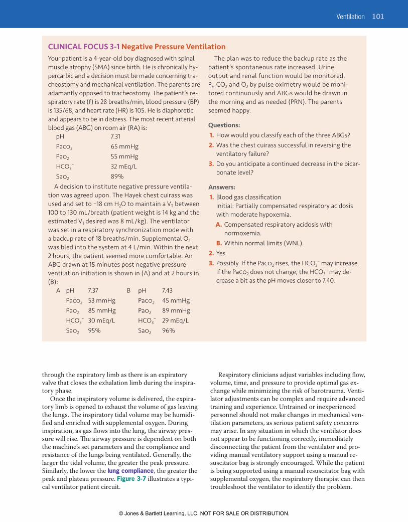
CLINICAL FOCUS 3-1 Negative Pressure VentilationYour patient is a 4-year-old boy diagnosed with spinal muscle atrophy (SMA) since birth. He is chronically hy-percarbic and a decision must be made concerning tra-cheostomy and mechanical ventilation. The parents are adamantly opposed to tracheostomy. The patient’s re-spiratory rate (f) is 28 breaths/min, blood pressure (BP) is 135/68, and heart rate (HR) is 105. He is diaphoretic and appears to be in distress. The most recent arterial blood gas (ABG) on room air (RA) is:
pH 7.31Paco2 65 mmHgPao2 55 mmHgHCO3
− 32 mEq/LSao2 89%
A decision to institute negative pressure ventila-tion was agreed upon. The Hayek chest cuirass was used and set to –18 cm H2O to maintain a VT between 100 to 130 mL/breath (patient weight is 14 kg and the estimated VT desired was 8 mL/kg). The ventilator was set in a respiratory synchronization mode with a backup rate of 18 breaths/min. Supplemental O2 was bled into the system at 4 L/min. Within the next 2 hours, the patient seemed more comfortable. An ABG drawn at 15 minutes post negative pressure ventilation initiation is shown in (A) and at 2 hours in (B):
A pH 7.37 B pH 7.43 Paco2 53 mmHg Paco2 45 mmHg Pao2 85 mmHg Pao2 89 mmHg HCO3
− 30 mEq/L HCO3− 29 mEq/L
Sao2 95% Sao2 96%
The plan was to reduce the backup rate as the patient’s spontaneous rate increased. Urine output and renal function would be monitored. PETCO2 and O2 by pulse oximetry would be moni-tored continuously and ABGs would be drawn in the morning and as needed (PRN). The parents seemed happy.
Questions:1. How would you classify each of the three ABGs?2. Was the chest cuirass successful in reversing the
ventilatory failure?3. Do you anticipate a continued decrease in the bicar-
bonate level?
Answers:1. Blood gas classification
Initial: Partially compensated respiratory acidosis with moderate hypoxemia.
A. Compensated respiratory acidosis with normoxemia.
B. Within normal limits (WNL).2. Yes.3. Possibly. If the Paco2 rises, the HCO3
− may increase. If the Paco2 does not change, the HCO3
− may de-crease a bit as the pH moves closer to 7.40.
Respiratory clinicians adjust variables including flow, volume, time, and pressure to provide optimal gas ex-change while minimizing the risk of barotrauma. Venti-lator adjustments can be complex and require advanced training and experience. Untrained or inexperienced personnel should not make changes in mechanical ven-tilation parameters, as serious patient safety concerns may arise. In any situation in which the ventilator does not appear to be functioning correctly, immediately disconnecting the patient from the ventilator and pro-viding manual ventilatory support using a manual re-suscitator bag is strongly encouraged. While the patient is being supported using a manual resuscitator bag with supplemental oxygen, the respiratory therapist can then troubleshoot the ventilator to identify the problem.
9781284139860_CH03_095_154.indd 101 21/02/19 5:37 PM
© Jones & Bartlett Learning, LLC. NOT FOR SALE OR DISTRIBUTION.

© Jones & Bartlett Learning, LLCNOT FOR SALE OR DISTRIBUTION
© Jones & Bartlett Learning, LLCNOT FOR SALE OR DISTRIBUTION
© Jones & Bartlett Learning, LLCNOT FOR SALE OR DISTRIBUTION
© Jones & Bartlett Learning, LLCNOT FOR SALE OR DISTRIBUTION
© Jones & Bartlett Learning, LLCNOT FOR SALE OR DISTRIBUTION
© Jones & Bartlett Learning, LLCNOT FOR SALE OR DISTRIBUTION
© Jones & Bartlett Learning, LLCNOT FOR SALE OR DISTRIBUTION
© Jones & Bartlett Learning, LLCNOT FOR SALE OR DISTRIBUTION
© Jones & Bartlett Learning, LLCNOT FOR SALE OR DISTRIBUTION
© Jones & Bartlett Learning, LLCNOT FOR SALE OR DISTRIBUTION
© Jones & Bartlett Learning, LLCNOT FOR SALE OR DISTRIBUTION
© Jones & Bartlett Learning, LLCNOT FOR SALE OR DISTRIBUTION
© Jones & Bartlett Learning, LLCNOT FOR SALE OR DISTRIBUTION
© Jones & Bartlett Learning, LLCNOT FOR SALE OR DISTRIBUTION
© Jones & Bartlett Learning, LLCNOT FOR SALE OR DISTRIBUTION
© Jones & Bartlett Learning, LLCNOT FOR SALE OR DISTRIBUTION
© Jones & Bartlett Learning, LLCNOT FOR SALE OR DISTRIBUTION
© Jones & Bartlett Learning, LLCNOT FOR SALE OR DISTRIBUTION
© Jones & Bartlett Learning, LLCNOT FOR SALE OR DISTRIBUTION
© Jones & Bartlett Learning, LLCNOT FOR SALE OR DISTRIBUTION
102 CHAPTER 3 Principles of Mechanical Ventilation
FIgURE 3-6 Pressure and Volume Ventilators Introduced in the 1940s Through the Early 1970s. Top left, the Bird Mark 7 (introduced in 1958) and Bird Mark 8 (introduced in 1959). Top right, the Bennett TV-2P (introduced in 1948) and Bennett PR-2 (introduced in 1963). Bottom left, Bennett MA-1 volume ventilator (introduced in 1967) and Servo 900 (introduced in 1971). Bottom right, the Ohio 560 (introduced in the 1970s). Reproduced from Kacmarek RM. The Mechanical Ventilator: Past, present, and future. Respir Care. Aug 2011;56(8):1170–1180; doi: 10.4187/respcare.01420
Figure 3-8 provides an example of ventilator graphics depicting the pressure curves associated with positive pressure volume ventilation with an end-expiratory pause. All pressures reflect proximal airway pressure (Paw), either measured directly or indirectly. Older
systems use a pressure monitoring line consisting of a length of noncompliant tubing that extends from the ventilator to the proximal airway “Y” connector. Most modern ventilators today sense the pressure where expired gas returns to the ventilator via the expiratory
9781284139860_CH03_095_154.indd 102 21/02/19 5:37 PM
© Jones & Bartlett Learning, LLC. NOT FOR SALE OR DISTRIBUTION.

© Jones & Bartlett Learning, LLCNOT FOR SALE OR DISTRIBUTION
© Jones & Bartlett Learning, LLCNOT FOR SALE OR DISTRIBUTION
© Jones & Bartlett Learning, LLCNOT FOR SALE OR DISTRIBUTION
© Jones & Bartlett Learning, LLCNOT FOR SALE OR DISTRIBUTION
© Jones & Bartlett Learning, LLCNOT FOR SALE OR DISTRIBUTION
© Jones & Bartlett Learning, LLCNOT FOR SALE OR DISTRIBUTION
© Jones & Bartlett Learning, LLCNOT FOR SALE OR DISTRIBUTION
© Jones & Bartlett Learning, LLCNOT FOR SALE OR DISTRIBUTION
© Jones & Bartlett Learning, LLCNOT FOR SALE OR DISTRIBUTION
© Jones & Bartlett Learning, LLCNOT FOR SALE OR DISTRIBUTION
© Jones & Bartlett Learning, LLCNOT FOR SALE OR DISTRIBUTION
© Jones & Bartlett Learning, LLCNOT FOR SALE OR DISTRIBUTION
© Jones & Bartlett Learning, LLCNOT FOR SALE OR DISTRIBUTION
© Jones & Bartlett Learning, LLCNOT FOR SALE OR DISTRIBUTION
© Jones & Bartlett Learning, LLCNOT FOR SALE OR DISTRIBUTION
© Jones & Bartlett Learning, LLCNOT FOR SALE OR DISTRIBUTION
© Jones & Bartlett Learning, LLCNOT FOR SALE OR DISTRIBUTION
© Jones & Bartlett Learning, LLCNOT FOR SALE OR DISTRIBUTION
© Jones & Bartlett Learning, LLCNOT FOR SALE OR DISTRIBUTION
© Jones & Bartlett Learning, LLCNOT FOR SALE OR DISTRIBUTION
Ventilation 103
limb of the circuit or within the internal ventilator cir-cuit near the point where gas leaves the internal circuit and enters the inspiratory limb of the external circuit.
Peak Inspiratory PressureThe peak inspiratory pressure (PIP) is the highest proximal airway pressure attained during the inspi-ratory phase. During pressure-control ventilation, PIP is determined by the ventilator settings. During volume-control (VC) ventilation, PIP can be influenced by set tidal volume (VT), inspiratory flow, inspiratory
flow waveform, resistance of the ventilator circuit/endotracheal tube, and lung mechanics (compliance and resistance). Proximal airway pressure may also in-crease during forced exhalation, as noted with cough (Box 3-3). Maintaining PIP < 35 cm H2O should reduce the risk of pulmonary barotrauma.
Plateau Pressure (Pplateau)In the VC mode, plateau pressure (Pplateau) is measured during an inspiratory hold maneuver, typically one second or less in duration (see again Figure 3-8). At the end of inspiration, with Pplateau activated, the ventilator will continue to block the exhalation valve as the airway pressure decreases from a peak value (PIP) to the pla-teau level. Under static conditions, Pplateau reflects alveo-lar pressure and the difference between PIP and Pplateau reflects airway resistance (Raw), which can be easily calculated during VC ventilation:
PIP – Pplateau
Inspiratory flow ( Lsec)
Pplateau is determined by elastic lung tissue recoil in the absence of airflow and allows for the calculation of static total compliance (CST) during VC ventilation:
CST = VT
Baseline Pressure and PEEPThe pressure waveform depicted in Figure 3-8 drops to a baseline or resting airway pressure during expiration. If the baseline pressure is the same as ambient pressure, the baseline is recorded as zero. If the baseline pressure during the expiratory phase is above ambient pressure, it is known as positive end-expiratory pressure (PEEP). PEEP has been used since the early days of positive pressure ventilation to maintain alveolar volumes dur-ing expiration and to improve oxygenation. Initially,
Raw =
Pplateau – baseline pressure
Monitoringline
Water trap
Temperatureports
Ventilator
Humidifier
INSP
EXP
FIgURE 3-7 An Example of a Mechanical Ventilator Patient Circuit. This circuit shows the inspiratory (green) and expiratory (gray) limbs that serve as a conduit of respirable gases between the ventilator (shown in gray) and the patient connection. A heated humidifier with attached water reservoir line is shown and heated internal wires maintain ventilator circuit temperature and reduce condensation.
AutoPEEPTotal-PEEP
PIP
Resistanceflow
Pplateau
Compliancetidal volume
PEEP
FIgURE 3-8 Airway Pressure During Volume-Controlled Ventilation: The Pressure vs Time Scalar. Peak inspiratory pressure (PIP) is the highest pressure reached during inspiration. An end inspiratory breath hold allows for measurement of plateau pressure (Pplateau). The difference between PIP and Pplateau represents airway resistance (Raw). PEEP is positive end-expiratory pressure. Introduction of an end expiratory pause allows for the measurement of autoPEEP.
BOX 3-3 Factors that Increase Peak Inspiratory Pressure (PIP)
� Increased peak inspiratory flow
� Increased set tidal volume (VT)
� Increased airway resistance
� Decreased total compliance
� Increased PEEP
� Kinked or obstructed ET tube
� Fighting the ventilator
� Coughing
9781284139860_CH03_095_154.indd 103 21/02/19 5:37 PM
© Jones & Bartlett Learning, LLC. NOT FOR SALE OR DISTRIBUTION.

© Jones & Bartlett Learning, LLCNOT FOR SALE OR DISTRIBUTION
© Jones & Bartlett Learning, LLCNOT FOR SALE OR DISTRIBUTION
© Jones & Bartlett Learning, LLCNOT FOR SALE OR DISTRIBUTION
© Jones & Bartlett Learning, LLCNOT FOR SALE OR DISTRIBUTION
© Jones & Bartlett Learning, LLCNOT FOR SALE OR DISTRIBUTION
© Jones & Bartlett Learning, LLCNOT FOR SALE OR DISTRIBUTION
© Jones & Bartlett Learning, LLCNOT FOR SALE OR DISTRIBUTION
© Jones & Bartlett Learning, LLCNOT FOR SALE OR DISTRIBUTION
© Jones & Bartlett Learning, LLCNOT FOR SALE OR DISTRIBUTION
© Jones & Bartlett Learning, LLCNOT FOR SALE OR DISTRIBUTION
© Jones & Bartlett Learning, LLCNOT FOR SALE OR DISTRIBUTION
© Jones & Bartlett Learning, LLCNOT FOR SALE OR DISTRIBUTION
© Jones & Bartlett Learning, LLCNOT FOR SALE OR DISTRIBUTION
© Jones & Bartlett Learning, LLCNOT FOR SALE OR DISTRIBUTION
© Jones & Bartlett Learning, LLCNOT FOR SALE OR DISTRIBUTION
© Jones & Bartlett Learning, LLCNOT FOR SALE OR DISTRIBUTION
© Jones & Bartlett Learning, LLCNOT FOR SALE OR DISTRIBUTION
© Jones & Bartlett Learning, LLCNOT FOR SALE OR DISTRIBUTION
© Jones & Bartlett Learning, LLCNOT FOR SALE OR DISTRIBUTION
© Jones & Bartlett Learning, LLCNOT FOR SALE OR DISTRIBUTION
104 CHAPTER 3 Principles of Mechanical Ventilation
PEEP was applied by simply submersing the distal end of the expiratory limb of the ventilator circuit below the surface of a water container. Early PEEP valve systems were developed (Figure 3-9) and attached to the ven-tilator and filled with a volume of water. The weight of the water over the ventilator’s exhalation valve created positive airway pressure during the expiratory phase proportional to the height of the water column in centi-meters. A water column 5 cm in height would result in PEEP of 5 cm H2O. Today’s ventilators use much more sophisticated systems incorporating servo-adjusted so-lenoid valves and pressure sensors to actively monitor and maintain airway pressures. PEEP set intentionally to improve lung volumes and oxygenation is known as extrinsic PEEP.
AutoPEEP or Intrinsic PEEPAir trapping (aka dynamic hyperinflation) can occur with incomplete emptying of the lung during expira-tion. Patients with obstructive lung disease are particu-larly prone to the development of air trapping during mechanical ventilation, especially if expiratory times are inadequate. Terms used for this air trapping dur-ing positive pressure ventilation include autoPEEP, or intrinsic PEEP.
AutoPEEP is not observable during positive pressure ventilation on the patient’s pressure-time curve without the use of an expiratory pause maneuver. Most modern ventilators allow for the introduction of an expiratory pause to evaluate autoPEEP Turning once again to Figure 3-8, note that as the pressure curve proceeds to the right, the pressure increases during an expiratory hold maneuver. This increased pressure is the autoPEEP
or intrinsic PEEP caused by air trapping during the ex-piratory phase. This dynamic hyperinflation can lead to higher mean airway pressures and possible cardiovascu-lar side effects (e.g., decreased venous return, decreased stroke volume, and decreased cardiac output). Patients with chronic obstructive pulmonary disease (COPD) are especially likely to develop autoPEEP
Optimal PEEPAs noted, the purpose of PEEP is to improve and maintain lung volumes and improve oxygenation in patients with acute restrictive pulmonary disease (e.g., pneumonia, acute respiratory distress syndrome [ARDS], pulmonary edema). A small amount of PEEP (3 to 5 cm H2O) has been suggested for most mechanically ventilated patients to prevent end-expiratory alveolar collapse; this is some-times referred to as “physiologic PEEP.” High levels of ex-trinsic PEEP can increase the transmural wall pressures of the low-pressure great vessels (superior and inferior vena cava) and the right and left ventricle. Compression of the vena cava can diminish venous return and ventricu-lar compression may affect diastolic filling. High levels of extrinsic PEEP combined with high levels of intrinsic PEEP (air trapping or autoPEEP) may further reduce ve-nous return. This assumes normal lung compliance as the transmural wall pressure effects are not as easily observed through noncompliant lungs.
One approach to optimizing PEEP titrates the PEEP level based on oxygen delivery (DO2). Recall that oxygen delivery is simply cardiac output times arterial oxygen content (DO2 = QT × Cao2). To achieve the optimal PEEP level, PEEP is increased incrementally followed by measurement of cardiac output or related parameters (blood pressure, mixed venous oxygen levels). The optimal PEEP level is the level that op-timizes DO2. Other approaches to optimizing PEEP levels include compliance-titrated PEEP and the use of pressure–volume curves to help set the PEEP level.
PEEP studies can be performed by comparing increases in set (extrinsic) PEEP to cardiac output. Clinical Focus 3-2 provides an example of a PEEP study used to determine optimum PEEP. Caution should be exercised in using high levels of PEEP in the setting of hypotension, hypovolemia, increased intracranial pressure (ICP), or pulmonary embolism.9
Mean Airway Pressure (Paw)In addition to the effect of PEEP on venous return, the respiratory care clinician should consider other variables that affect mean airway pressure (Paw) dur-ing mechanical ventilation with positive pressure. A 2003 paper on mathematical modeling of mean airway pressure used PEEP, I:E ratios, and Pplateau to make de-terminations of mean airway pressures.10 This article suggests using a target airway pressure to recruit alveoli rather than using arterial blood gas analysis, PETCO2,
FIgURE 3-9 The Water-Filled PEEP Column.Courtesy Dr. Greg Holt.
9781284139860_CH03_095_154.indd 104 21/02/19 5:37 PM
© Jones & Bartlett Learning, LLC. NOT FOR SALE OR DISTRIBUTION.

© Jones & Bartlett Learning, LLCNOT FOR SALE OR DISTRIBUTION
© Jones & Bartlett Learning, LLCNOT FOR SALE OR DISTRIBUTION
© Jones & Bartlett Learning, LLCNOT FOR SALE OR DISTRIBUTION
© Jones & Bartlett Learning, LLCNOT FOR SALE OR DISTRIBUTION
© Jones & Bartlett Learning, LLCNOT FOR SALE OR DISTRIBUTION
© Jones & Bartlett Learning, LLCNOT FOR SALE OR DISTRIBUTION
© Jones & Bartlett Learning, LLCNOT FOR SALE OR DISTRIBUTION
© Jones & Bartlett Learning, LLCNOT FOR SALE OR DISTRIBUTION
© Jones & Bartlett Learning, LLCNOT FOR SALE OR DISTRIBUTION
© Jones & Bartlett Learning, LLCNOT FOR SALE OR DISTRIBUTION
© Jones & Bartlett Learning, LLCNOT FOR SALE OR DISTRIBUTION
© Jones & Bartlett Learning, LLCNOT FOR SALE OR DISTRIBUTION
© Jones & Bartlett Learning, LLCNOT FOR SALE OR DISTRIBUTION
© Jones & Bartlett Learning, LLCNOT FOR SALE OR DISTRIBUTION
© Jones & Bartlett Learning, LLCNOT FOR SALE OR DISTRIBUTION
© Jones & Bartlett Learning, LLCNOT FOR SALE OR DISTRIBUTION
© Jones & Bartlett Learning, LLCNOT FOR SALE OR DISTRIBUTION
© Jones & Bartlett Learning, LLCNOT FOR SALE OR DISTRIBUTION
© Jones & Bartlett Learning, LLCNOT FOR SALE OR DISTRIBUTION
© Jones & Bartlett Learning, LLCNOT FOR SALE OR DISTRIBUTION
Ventilation 105
and oximetry alone for ventilator adjustments. The in-creased focus on the balance of I:E ratios and PEEP with particular attention to inspiratory time (TI) to manage Paw over PEEP settings was the intent of the paper.10 A less stringent method forwards the equation Paw = ½ (PIP – PEEP) × (TI / Ttot) + PEEP. The effect of PEEP is
direct, and a 1 cm H2O PEEP increase causes a 1 cm H2O rise in Paw. Factors that increase TI will increase Paw. Changes in pulmonary mechanics (e.g., low lung compliance and high airflow resistance) also may con-tribute to an increased Paw. Variables that can influence mean airway pressure are described in Box 3-4.
CLINICAL FOCUS 3-2 Optimal PEEP StudyAn optimal PEEP study is requested for a patient on mechanical ventilation with settings:
Mode: PC-ACFio2: 100%PIP: 28 cm H2ORR: 16 bpmPEEP: +12 cm H2O
Recent ABG results: pH 7.30Paco2 60 mmHgPao2 45 mmHg
PEEP Sao2 BP CO DO2 PCWP CST C(a-v)O2
12 73 104/60 6.3 649 20 27 3.3
14 80 105/64 6.3 693 18 30 3.6
16 82 100/58 6.2 700 16 36 4.1
18 92 105/68 6.0 768 16 48 5.6
20 100 95/55 5.8 806 17 37 6.3
22 100 80/52 5.3 736 20 33 6.0
24 100 65/40 5.1 714 23 23 4.4
HCO3− 29 mEq/L
Hg 10 g/dLThe patient’s ventilator indicates a delivered VT of 400 mL, and there are no spontaneous respirations. The patient has increasing patchy infiltrates on chest x-ray. A PEEP study has been ordered, and you have developed the following table. All measures were made at an Fio2 of 100% with a Hb of 10 g/100 mL blood. The results displayed were obtained after 10 minutes at each PEEP level.
Questions:1. How would you interpret the patient’s initial
(recent) ABG?2. What level of PEEP could be considered optimal?3. What are other variables that can be used to de-
velop an optimal PEEP study?
Answers: 1. The recent blood gas shows a partially compen-
sated respiratory acidosis with moderate to severe hypoxemia.
2. At PEEP of 18 cm H2O the BP, Sao2, CO, and DO2,
and C(a-v)O2 are acceptable and CST is at its highest value (48) suggesting that this represents the best or optimal PEEP level. Although DO2 is highest at
the next PEEP level (20 cm H2O), blood pressure, cardiac output, and compliance decrease and C(a-v)O2 increases.
3. Many variables can be used to help determine optimal PEEP. They include hemodynamic mea-sures, lung mechanics, and indices of oxygenation and ventilation (e.g., BP, CO, CI, DO2, Pv–O2, Sv–O2, C(a-vO2), Pao2, Sao2, P(A-a), Pao2/Fio2, CST, Paco2 – PETCO2, and shunt fraction [QS/QT]).
ABG, arterial blood gas; BP, blood pressure; CO, cardiac output; CST, static compliance; PC-AC, pressure control-assist control; PCWP, pulmonary capillary wedge pressure; PEEP, positive end-expiratory pressure; PIP, peak inspiratory pressure; RR, respiratory rate.
9781284139860_CH03_095_154.indd 105 21/02/19 5:37 PM
© Jones & Bartlett Learning, LLC. NOT FOR SALE OR DISTRIBUTION.

© Jones & Bartlett Learning, LLCNOT FOR SALE OR DISTRIBUTION
© Jones & Bartlett Learning, LLCNOT FOR SALE OR DISTRIBUTION
© Jones & Bartlett Learning, LLCNOT FOR SALE OR DISTRIBUTION
© Jones & Bartlett Learning, LLCNOT FOR SALE OR DISTRIBUTION
© Jones & Bartlett Learning, LLCNOT FOR SALE OR DISTRIBUTION
© Jones & Bartlett Learning, LLCNOT FOR SALE OR DISTRIBUTION
© Jones & Bartlett Learning, LLCNOT FOR SALE OR DISTRIBUTION
© Jones & Bartlett Learning, LLCNOT FOR SALE OR DISTRIBUTION
© Jones & Bartlett Learning, LLCNOT FOR SALE OR DISTRIBUTION
© Jones & Bartlett Learning, LLCNOT FOR SALE OR DISTRIBUTION
© Jones & Bartlett Learning, LLCNOT FOR SALE OR DISTRIBUTION
© Jones & Bartlett Learning, LLCNOT FOR SALE OR DISTRIBUTION
© Jones & Bartlett Learning, LLCNOT FOR SALE OR DISTRIBUTION
© Jones & Bartlett Learning, LLCNOT FOR SALE OR DISTRIBUTION
© Jones & Bartlett Learning, LLCNOT FOR SALE OR DISTRIBUTION
© Jones & Bartlett Learning, LLCNOT FOR SALE OR DISTRIBUTION
© Jones & Bartlett Learning, LLCNOT FOR SALE OR DISTRIBUTION
© Jones & Bartlett Learning, LLCNOT FOR SALE OR DISTRIBUTION
© Jones & Bartlett Learning, LLCNOT FOR SALE OR DISTRIBUTION
© Jones & Bartlett Learning, LLCNOT FOR SALE OR DISTRIBUTION
106 CHAPTER 3 Principles of Mechanical Ventilation
Invasive vs. Noninvasive VentilationBefore comparing the similarities and differences be-tween invasive and noninvasive ventilation, we should revisit the goal of mechanical ventilation: to support oxygenation and CO2 removal. Mechanical ventila-tion requires a trigger (breath initiation), a limit (size of the breath), and a cycle (transition of inspiration to expiration). The forms the trigger, limit, and cycle vari-ables take are dependent on the device, the patient’s condition, and the level of expertise of the respiratory care clinician.
Similarities between invasive and noninvasive ven-tilation (NIV) include positive pressure breath delivery and the ventilator’s airway pressure and flow sensing ca-pabilities. Many new noninvasive devices can measure volume directly. Size and cost of ventilators designed for invasive vs noninvasive use are major differences between the two. For example, simple NIV devices for the treatment of obstructive sleep apnea (OSA) may cost as little as $600 and fit on a nightstand, while a sophisticated critical care ventilator may cost $35,000 or more and require significant space at the bedside. NIV requires a spontaneously breathing patient with an adequate respiratory drive, while a critical care ventila-tor can ventilate apneic patients with acute or chronic respiratory failure. Another difference between NIV and invasive ventilation is the interface between the patient and the ventilator. Both methods require a sealed airway to deliver positive pressure, but invasive ventilation re-quires an endotracheal or tracheostomy tube be placed with the cuff inflated.
Noninvasive VentilationNIV can be used to provide ventilatory support to patients with a wide variety of conditions, which may be acute or chronic. For example, in the acute care setting, NIV is often used to support patients with
acute exacerbations of COPD. Extubation to NIV has also been recommended for certain patients at risk of extubation failure. NIV is also sometimes used in patients with chronic neuromuscular disease. NIV for the treatment of obstructive sleep apnea will be briefly discussed below.
NIV has seen great strides in technology and mask interface devices in the treatment of obstructive sleep apnea (OSA) since the mid-1990s. Companies such as ResMed, Respironics, and Fisher-Paykel have invested resources into research and development of better patient-sensing capabilities, improved mask comfort and fit, and new modes of NIV. For example, Respiron-ics developed an expiratory pressure release technol-ogy (CFLEX) adjustable from 0 to 3, with 3 providing the greatest drop in exhaled pressure. CFLEX may improve patient comfort and compliance. ResMed fol-lowed closely with EPR (expiratory pressure release) that has an adjustable, set pressure drop at the start of exhalation.
The relief of patient anxiety associated with the higher pressures sometimes necessary to control OSA was the driving force behind CFLEX and EPR development. If higher pressures (e.g., > 12 cm H2O) were used in OSA therapy, patients often com-plained of difficulty exhaling against the pressure. Bilevel positive airway pressure (BiPAP) would be sometimes instituted (Box 3-5), but this added to the cost of the device. A variation on BiPAP was developed, the spontaneous-timed (S/T) mode. With BiPAP S/T (trademark Respironics), inspiratory and expiratory pressures were set along with a backup rate. If the de-vice measured zero inspiratory flow for a set period, the inspiratory positive airway pressure (IPAP) breath would be delivered (i.e., time triggered to inspiration). BiPAP S/T could provide support for some cases of complex sleep apnea (defined as at least 50% of all respi-ratory events being central in origin); however, the IPAP breath could fall short of preventing sleep arousal as seen via EEG and O2 desaturation. If the IPAP pressures
BOX 3-4 Factors That May Increase Mean Airway Pressure (Paw)
� Increased inspiratory time
� Increased I:E ratio
� Decreased expiratory time
� Increased tidal volume
� Increased extrinsic PEEP
� AutoPEEP
� Decreased spontaneous breathing
� Down-ramp (decreasing) inspiratory flow pattern
� Low lung compliance
� High airway resistance (Raw)
BOX 3-5 Bilevel Positive Airway Pressure (BiPAP) for OSA
� BiPAP can be expressed as a combination of IPAP over EPAP.
� IPAP can reach 30 cm H2O.
� EPAP is usually 4 to 8 cm H2O below IPAP.
� EPAP is set to abolish obstructive apneas.
� IPAP is set to improve the inspiratory flow wave characteristics and abolish hypopneas and snoring.
IPAP: inspiratory positive airway pressure; EPAP: expiratory positive airway pressure.
9781284139860_CH03_095_154.indd 106 21/02/19 5:37 PM
© Jones & Bartlett Learning, LLC. NOT FOR SALE OR DISTRIBUTION.

© Jones & Bartlett Learning, LLCNOT FOR SALE OR DISTRIBUTION
© Jones & Bartlett Learning, LLCNOT FOR SALE OR DISTRIBUTION
© Jones & Bartlett Learning, LLCNOT FOR SALE OR DISTRIBUTION
© Jones & Bartlett Learning, LLCNOT FOR SALE OR DISTRIBUTION
© Jones & Bartlett Learning, LLCNOT FOR SALE OR DISTRIBUTION
© Jones & Bartlett Learning, LLCNOT FOR SALE OR DISTRIBUTION
© Jones & Bartlett Learning, LLCNOT FOR SALE OR DISTRIBUTION
© Jones & Bartlett Learning, LLCNOT FOR SALE OR DISTRIBUTION
© Jones & Bartlett Learning, LLCNOT FOR SALE OR DISTRIBUTION
© Jones & Bartlett Learning, LLCNOT FOR SALE OR DISTRIBUTION
© Jones & Bartlett Learning, LLCNOT FOR SALE OR DISTRIBUTION
© Jones & Bartlett Learning, LLCNOT FOR SALE OR DISTRIBUTION
© Jones & Bartlett Learning, LLCNOT FOR SALE OR DISTRIBUTION
© Jones & Bartlett Learning, LLCNOT FOR SALE OR DISTRIBUTION
© Jones & Bartlett Learning, LLCNOT FOR SALE OR DISTRIBUTION
© Jones & Bartlett Learning, LLCNOT FOR SALE OR DISTRIBUTION
© Jones & Bartlett Learning, LLCNOT FOR SALE OR DISTRIBUTION
© Jones & Bartlett Learning, LLCNOT FOR SALE OR DISTRIBUTION
© Jones & Bartlett Learning, LLCNOT FOR SALE OR DISTRIBUTION
© Jones & Bartlett Learning, LLCNOT FOR SALE OR DISTRIBUTION
Ventilation 107
were increased to cover the reduced machine delivered tidal volume, the patient could arouse and awaken to some very high pressures.
The next generation of NIV to treat central sleep apnea and forms of complex sleep apnea was automatic-servo ventilation (auto-SV, trademark Respi-ronics) and later adaptive-servo ventilation (trademark ResMed). Auto-SV was considered a respiratory assist device, similar to BiPAP S/T with pressure support. Auto-SV would “view” the patient’s rate and volume when the device was initiated (patient awake) and mimic that pattern during the night. If the tidal vol-umes fell short, pressure support would be added to increase volume (Figure 3-10) The auto-SV would in-crease pressures to cover obstructive respiratory events with an adjustable range of pressures; the rate could be set or left in an auto-detection mode and the level of pressure support could be set as a fixed number or range for auto-adjust. These added features, however, result in a cost approximately 5 times the cost of a basic CPAP device.
Automatic positive airway pressure or autoPAP is a device that continues to be ordered for OSA treatment. The pressure range for autoPAP is adjustable from 4 to 20 cm H2O. By algorithm, the device can detect a re-duced or absent inspiratory flow and stepwise increase the delivered pressure. There are problems, however, associated with autoPAP. Primary among them is the in-ability to detect central versus obstructive sleep apnea. Some units will not increase pressure over 10 cm H2O unless there is a secondary indication of obstructive respiratory events, such as the acoustical vibration of snoring. A known problem of positive pressure therapy noted during a CPAP titration study for OSA is the po-tential for central apnea generation at higher pressures. A second problem and more likely occurrence is a sub-therapeutic pressure range set on autoPAP. Picking the autoPAP pressure range without the benefit of a CPAP
titration study is a guess. If the pressure range is left at its initial setting, 4 to 20 cmH2O, the patient (especially a very tall patient) may inspire with a greater flow than delivered and a feeling of air hunger may result. If the patient on the same settings with OSA is asleep, the autoPAP will respond to his or her apnea by detection and will increase pressure provided. Over time, the pa-tient will either get to the point where the attained pres-sure allows for ventilation or the patient may arouse and roll to his or her side, where the device lowers the pres-sure to a new baseline. Put another way, sleep-disordered breathing is required to reach the appropriate thera-peutic pressure. The patient may also awaken and feel that the device is not working at all. This could result in reduced compliance. Ideally, the clinician should know the appropriate pressures for each patient that treat OSA while supine, on the patient’s side, and in REM sleep. The autoPAP device could then be set with a minimum pressure treating OSA while on the patient’s side with the idea that the pressures may not be too far from controlling OSA while in supine REM sleep. Minimally, the clinician should follow any patient on autoPAP with overnight oximetry to assess therapeutic effectiveness. Suggested indications for autoPAP are noted in Box 3-6.
Invasive VentilationInvasive positive pressure ventilation opens a wide array of ventilatory capabilities using sophisticated critical care ventilators. The goals remain the same, including assuring oxygenation needs are met and sup-porting ventilation until the patient can return to his or her baseline ventilatory status. Modern critical care ventilators have sophisticated alarms and monitor-ing systems, advanced graphic displays, and a wide array of modes available ranging from conventional volume-control continuous mandatory ventilation (VC-CMV) to pressure-control continuous mandatory
Decrease inpressuresupport
Crescendo
17
9
Decrescendo
Increase inpressuresupport
Pressureassist
Centralapnea
Flow
EPAP 7cm H2O
IPAPmin
IPAPmax
Backuprate
FIgURE 3-10 Automatic-Servo Ventilation. Pressure support is automatically adjusted to minimize fluctuations in VT and prevent airway obstruction. If central apneas arise, the backup rate will deliver IPAP-associated breaths.
BOX 3-6 Indications for Automatic Positive Airway Pressure (autoPAP)
1. Initial therapy to treat OSA prior to CPAP titration
2. AutoPAP trial after significant weight change to adjust CPAP pressure
3. Patient c/o aerophagia (air swallowing) while on CPAP
4. As primary therapy if optimal pressures are known: side, supine, REM
5. As primary therapy in patients with mild OSA and low BMI
BMI, body mass index; CPAP, continuous positive airway pres-sure; OSA, obstructive sleep apnea; REM, rapid eye movement sleep
9781284139860_CH03_095_154.indd 107 21/02/19 5:37 PM
© Jones & Bartlett Learning, LLC. NOT FOR SALE OR DISTRIBUTION.

© Jones & Bartlett Learning, LLCNOT FOR SALE OR DISTRIBUTION
© Jones & Bartlett Learning, LLCNOT FOR SALE OR DISTRIBUTION
© Jones & Bartlett Learning, LLCNOT FOR SALE OR DISTRIBUTION
© Jones & Bartlett Learning, LLCNOT FOR SALE OR DISTRIBUTION
© Jones & Bartlett Learning, LLCNOT FOR SALE OR DISTRIBUTION
© Jones & Bartlett Learning, LLCNOT FOR SALE OR DISTRIBUTION
© Jones & Bartlett Learning, LLCNOT FOR SALE OR DISTRIBUTION
© Jones & Bartlett Learning, LLCNOT FOR SALE OR DISTRIBUTION
© Jones & Bartlett Learning, LLCNOT FOR SALE OR DISTRIBUTION
© Jones & Bartlett Learning, LLCNOT FOR SALE OR DISTRIBUTION
© Jones & Bartlett Learning, LLCNOT FOR SALE OR DISTRIBUTION
© Jones & Bartlett Learning, LLCNOT FOR SALE OR DISTRIBUTION
© Jones & Bartlett Learning, LLCNOT FOR SALE OR DISTRIBUTION
© Jones & Bartlett Learning, LLCNOT FOR SALE OR DISTRIBUTION
© Jones & Bartlett Learning, LLCNOT FOR SALE OR DISTRIBUTION
© Jones & Bartlett Learning, LLCNOT FOR SALE OR DISTRIBUTION
© Jones & Bartlett Learning, LLCNOT FOR SALE OR DISTRIBUTION
© Jones & Bartlett Learning, LLCNOT FOR SALE OR DISTRIBUTION
© Jones & Bartlett Learning, LLCNOT FOR SALE OR DISTRIBUTION
© Jones & Bartlett Learning, LLCNOT FOR SALE OR DISTRIBUTION
108 CHAPTER 3 Principles of Mechanical Ventilation
ventilation (PC-CMV), to inverse ratio ventilation, to various permutations of intermittent mandatory ven-tilation (IMV), to various volume targeting schemes (e.g., pressure-regulated volume control [PRVC], volume support [VS], and adaptive pressure con-trol [APC]). Modern critical care ventilators also often have many adjunct features and modes in-cluding automatic tube compensation (ATC), airway pressure release ventilation (APRV), propor-tional assist ventilation (PAV), or adaptive support ventilation (ASV), as well as the capability to provide NIV. Many of these modes will be introduced later in
this chapter. The ventilation of the patient with acute respiratory failure superimposed on chronic respiratory failure is described in Clinical Focus 3-3.
Ventilator InitiationIndications for mechanical ventilation and ventilator ini-tiation are described in Chapters 5 and 6. Once the deci-sion to provide ventilatory support is made, mechanical ventilation is initiated within specific parameters. Typi-cally, orders will be given for mode, Fio2, VT (or PIP), respiratory rate, PEEP, and pressure support. Some in-stitutions allow for ventilator initiation and adjustments
CLINICAL FOCUS 3-3 Acute Ventilatory Failure Superimposed on Chronic Ventilatory FailureMrs. Ortiz is a 78-year-old female with a 110 pack-year history of smoking. She has been diagnosed with COPD and her “normal” arterial blood gas consists of pH 7.36, Paco2 55 mmHg, and Pao2 60 mmHg on room air. Her HCO3
− is calculated to be 30 mEq/L. She develops pneumonia and presents to the emer-gency department in respiratory distress. Her ABG results in the ED are: pH 7.21, Paco2 70 mmHg, and Pao2 45 mmHg, with HCO3
− 34 mEq/L. Her condi-tion worsens, and she is intubated and placed on mechanical ventilation. Her ventilation is supported to maintain arterial blood gases similar to her base-line: compensated respiratory acidosis with mild hypoxemia. Intravenous antibiotics are administered until resolution of the pneumonia. Mrs. Ortiz is weaned from mechanical ventilation, extubated, and discharged.
To summarize, Mrs. Ortiz’s “normal” baseline can be described as chronic ventilatory failure (com-pensated respiratory acidosis) and mild hypoxemia. Following acute exacerbation of his COPD, she de-veloped acute on chronic ventilatory failure with a partially compensated respiratory acidosis and severe hypoxemia. Following treatment, resolution of her pneumonia and ventilator discontinuance, she has returned to her baseline status of chronic ventilatory failure.
Mrs. Ortiz might have taken another path if the development of worsening respiratory failure had progressed more slowly allowing for further renal compensation of a worsening Paco2. In this second example, the original ABG is followed by worsening ventilatory status with renal compensation, then re-spiratory failure, and finally, mechanical ventilation is initiated with overventilation.
(A) Initial ABg
(B) 1 Week
of Illness
(C) Respiratory
Failure
(D) Mechanical Ventilation
pH 7.36 7.39 7.29 7.62Paco2 55 68 86 40Pao2 60 50 45 60HCO3
− 30 40 40 40
Questions:1. Review the ABGs and determine their classifica-
tions for A, B, C, and D.2. When mechanical ventilation is instituted and the
Paco2 is “normal” at 40 mmHg, what is causing the apparent metabolic alkalosis?
3. Would it have been more appropriate to ventilate this patient to her baseline Paco2 of 55 mmHg?
Answers: 1. A. Compensated respiratory acidosis with mild
hypoxemia (chronic ventilatory failure); B. Compen-sated respiratory acidosis with moderate hypoxemia (chronic ventilatory failure); C. Partially compen-sated respiratory acidosis with moderate hypoxemia (acute ventilatory failure superimposed on chronic ventilatory failure); D. While this looks like an un-compensated metabolic alkalosis with mild hypox-emia, it is a relative hyperventilation with respect to the patient’s baseline Paco2 of 55, resulting in alka-losis. The ventilatory settings should be adjusted.
2. This patient’s “normal” baseline Paco2 is 55 mm Hg resulting in a pH of 7.36 (see initial ABG - A). If the initial ventilator settings result in a Paco2 of 40, the pH will increase as noted (see ABG Mechanical Ventilation - D). The ventilator settings have created a relative hyperventilation with respect to the pa-tient’s baseline Paco2 of 55 resulting in an alkalosis.
3. Yes. The targeted Paco2 should have been the pa-tient’s “normal” baseline (i.e., Paco2 = 55).
9781284139860_CH03_095_154.indd 108 21/02/19 5:37 PM
© Jones & Bartlett Learning, LLC. NOT FOR SALE OR DISTRIBUTION.

© Jones & Bartlett Learning, LLCNOT FOR SALE OR DISTRIBUTION
© Jones & Bartlett Learning, LLCNOT FOR SALE OR DISTRIBUTION
© Jones & Bartlett Learning, LLCNOT FOR SALE OR DISTRIBUTION
© Jones & Bartlett Learning, LLCNOT FOR SALE OR DISTRIBUTION
© Jones & Bartlett Learning, LLCNOT FOR SALE OR DISTRIBUTION
© Jones & Bartlett Learning, LLCNOT FOR SALE OR DISTRIBUTION
© Jones & Bartlett Learning, LLCNOT FOR SALE OR DISTRIBUTION
© Jones & Bartlett Learning, LLCNOT FOR SALE OR DISTRIBUTION
© Jones & Bartlett Learning, LLCNOT FOR SALE OR DISTRIBUTION
© Jones & Bartlett Learning, LLCNOT FOR SALE OR DISTRIBUTION
© Jones & Bartlett Learning, LLCNOT FOR SALE OR DISTRIBUTION
© Jones & Bartlett Learning, LLCNOT FOR SALE OR DISTRIBUTION
© Jones & Bartlett Learning, LLCNOT FOR SALE OR DISTRIBUTION
© Jones & Bartlett Learning, LLCNOT FOR SALE OR DISTRIBUTION
© Jones & Bartlett Learning, LLCNOT FOR SALE OR DISTRIBUTION
© Jones & Bartlett Learning, LLCNOT FOR SALE OR DISTRIBUTION
© Jones & Bartlett Learning, LLCNOT FOR SALE OR DISTRIBUTION
© Jones & Bartlett Learning, LLCNOT FOR SALE OR DISTRIBUTION
© Jones & Bartlett Learning, LLCNOT FOR SALE OR DISTRIBUTION
© Jones & Bartlett Learning, LLCNOT FOR SALE OR DISTRIBUTION
Ventilator Principles 109
per protocol. Initial ventilator settings are keyed into the ventilator’s control interface. The respiratory therapist typically chooses the patient-trigger method, trigger ef-fort, inspiratory time or flow, and flow waveform (VC modes), and adjusts settings to ensure patient–ventila-tor synchrony and effective ventilation. Alarm settings are entered, and patient response as assessed.
Assessment to ensure successful achievement of ventilatory support goals begins immediately. This will include patient appearance, breath sounds, and assess-ment of ventilator volumes, pressures, and flows. As-sessment of oxygenation (Spo2), ventilation (respiratory rate, VT, VE, arterial blood gases, and end-tidal CO2), and cardiovascular status (HR, BP, ECG) should follow. Clinicians should be reminded that when mechanical ventilation does not appear to be functioning prop-erly, the ventilator should be disconnected, and bag ventilation resumed until proper ventilator operation and airway patency can be confirmed. Initial problems sometimes encountered when the patient is placed on the ventilator may be due to pain and anxiety, inade-quate oxygenation or ventilation, cardiac/cardiovascular problems, or improper ventilator settings. Solutions may be as simple as altering the ventilator settings, se-dation (anxiety) and analgesia (pain), or suctioning to remove secretions from the airway. Airway problems include secretions, obstruction, or bronchospasm, all of which may cause triggering of high-pressure alarms in the VC mode and decreased VT in the PC mode. For example, the endotracheal tube may be out of position, kinked, or partially occluded. Breath sound assess-ment and attempting to pass a suction catheter can sometimes identify the cause. Other serious problems include pneumothorax, pulmonary edema, pulmonary embolus, or cardiovascular compromise. Once the pa-tient is stable, comfortable, and adequately oxygenated and ventilated, a regular program of assessment, moni-toring, and care is instituted.
Ventilator PrinciplesInput Power and Control SystemsMechanical ventilators must incorporate a power source to perform the work required, known as the in-put power. Power sources may be pneumatic or electric. Pneumatically powered ventilators connect to an exter-nal high-pressure gas source, while electrically powered ventilators use electricity to power internal compres-sors, blowers, pistons, or bellows. Ventilator control systems use pneumatic valves, electrical circuits, or mi-croprocessor controls to regulate oxygen concentrations and gas flow to the patient.
Pneumatically Powered VentilatorsPneumatically powered ventilators require a com-pressed gas source, either air or oxygen or both. Older pneumatic ventilators were powered using only one
compressed gas source. These older pneumatically powered ventilators (e.g., Bird Mark 7, Bennett PR-2) in-corporated needle valves, flexible diaphragms, ceramic valves, pneumatic bleed-down cartridges, flow-sensitive valves, and Venturi devices to perform the various functions required to ventilate patients. These devices could be powered by 100% oxygen, which could be di-luted using an on/off venture device to provide 100% O2 or a moderate concentration oxygen (40% to 60%). These ventilators also could be powered by compressed air to provide 21% oxygen or blended gas to provide a precise FIO2.
Modern pneumatically powered ventilators require two 50-psi compressed gas sources (air and oxygen) and incorporate microprocessor-controlled valves to pro-vide the desired oxygen concentration and gas flows to the patient. These are known as pneumatically powered microprocessor-controlled ventilators.
Electrically Powered VentilatorsThe first truly sophisticated modern critical care ven-tilators were electrically powered and controlled and incorporated internal air compressors, blowers, bellows, or pistons to deliver gas to the patient. These ventilators were introduced in the 1960s and 1970s and allowed for precise control of Fio2, delivered tidal volume, respira-tory rate, and inspiratory flow or time. PEEP was an integrated feature and the ventilators could be used to provide patient- or time-triggered ventilation (assist-control or A/C). By the 1970s, intermittent mandatory ventilation (IMV) and synchronized intermittent man-datory ventilation (SIMV) became common options. Classic electrically powered ventilators included the MA-1, Ohio 560, Emerson 3PV and IMV Emerson, and Bear series (e.g., Bear-1, Bear-2, Bear-3). These ventilators could be described as single circuit, in which the gas power source was sent directly to the pa-tient, or double circuit, in which the gas power source was directed to a bellows housed within a canister. Single-circuit devices included the rotary piston, IMV Emerson, and the Bear series. Double-circuit systems, such as the MA-1 and Ohio 560, used a blower or com-pressor to push a bellows containing mixed gas upward; the gas within the bellows would then be delivered to the patient (blower-bellows system). These ventilators were extremely efficient, safe, and reliable and allowed for the development of the sophisticated approach to critical care and support of the patient in respiratory failure that we see today.
Control SystemsMost modern critical care ventilators today are micro-processor controlled and require a 120-volt continuous electrical supply with stepped-down resistors reducing voltage to control various onboard ventilator systems. Most ventilators possess a battery backup designed to continue ventilation until a substitute power supply
9781284139860_CH03_095_154.indd 109 21/02/19 5:37 PM
© Jones & Bartlett Learning, LLC. NOT FOR SALE OR DISTRIBUTION.

© Jones & Bartlett Learning, LLCNOT FOR SALE OR DISTRIBUTION
© Jones & Bartlett Learning, LLCNOT FOR SALE OR DISTRIBUTION
© Jones & Bartlett Learning, LLCNOT FOR SALE OR DISTRIBUTION
© Jones & Bartlett Learning, LLCNOT FOR SALE OR DISTRIBUTION
© Jones & Bartlett Learning, LLCNOT FOR SALE OR DISTRIBUTION
© Jones & Bartlett Learning, LLCNOT FOR SALE OR DISTRIBUTION
© Jones & Bartlett Learning, LLCNOT FOR SALE OR DISTRIBUTION
© Jones & Bartlett Learning, LLCNOT FOR SALE OR DISTRIBUTION
© Jones & Bartlett Learning, LLCNOT FOR SALE OR DISTRIBUTION
© Jones & Bartlett Learning, LLCNOT FOR SALE OR DISTRIBUTION
© Jones & Bartlett Learning, LLCNOT FOR SALE OR DISTRIBUTION
© Jones & Bartlett Learning, LLCNOT FOR SALE OR DISTRIBUTION
© Jones & Bartlett Learning, LLCNOT FOR SALE OR DISTRIBUTION
© Jones & Bartlett Learning, LLCNOT FOR SALE OR DISTRIBUTION
© Jones & Bartlett Learning, LLCNOT FOR SALE OR DISTRIBUTION
© Jones & Bartlett Learning, LLCNOT FOR SALE OR DISTRIBUTION
© Jones & Bartlett Learning, LLCNOT FOR SALE OR DISTRIBUTION
© Jones & Bartlett Learning, LLCNOT FOR SALE OR DISTRIBUTION
© Jones & Bartlett Learning, LLCNOT FOR SALE OR DISTRIBUTION
© Jones & Bartlett Learning, LLCNOT FOR SALE OR DISTRIBUTION
110 CHAPTER 3 Principles of Mechanical Ventilation
is provided (generator backup). Some deep-cycle gel batteries can last 10 hours, but many systems are not designed to support ventilation for more than 2 hours. There have been reported cases of ventilator failure due to batteries beyond their useful life not accepting a charge and faulty battery level indicators. If backup electrical power systems do not respond immediately, the clinician should resume bag ventilation using a manual resuscitator bag. Most modern critical care ventilators also require high-pressure gas sources, both oxygen and compressed air in most cases. Like backup electrical supply, some mechanical ventilators possess onboard gas compressors capable of driving ventilator functions. The usual case is connecting both oxygen and air to 50-psi sources. Piped in medical gas supply systems are built into the walls of hospitals with mul-tiple air and oxygen outlets in each modern ICU room. Large, liquid oxygen systems and powerful medical gas air compressors provide the sources for compressed air and oxygen.
Ventilators incorporate pressure regulation devices and solenoid controllers to provide the desired air/O2 mix to deliver the desired Fio2 and gas flow to the pa-tient. These pressure/flow regulation devices may incor-porate a pneumatic diaphragm, electromagnetic valve, poppet/plunger valve, or microprocessor- controlled proportional solenoid valves.4 The control system of a mechanical ventilator generally uses a combination of pressure and electrical/microprocessor-controlled sys-tems to shape and deliver the breath.
Control systems may be open loop or closed loop. An open-loop system does not incorporate a feedback signal to assure a specific ventilator parameter has been met. For example, a ventilator in which a micro-processor control system is used to set a specific tidal volume may have no feedback system to adjust gas flow in the presence of a change in actual delivered tidal. A closed-loop system uses a microprocessor-controlled feedback system to adjust gas flow based on measured values. For example, with a closed-loop system the op-erator may set a specific tidal volume. The ventilator then compares the actual delivered volume to the set value and adjusts gas delivery based on the compari-son. Adaptive targeting for tidal volume using pres-sure support or pressure control provides an example of a closed-loop control system known as adaptive pressure control (APC). APC is available as pressure-regulated volume control (PRVC, Getinge Servo-i), auto flow (Dräger Evita Infinity v500), adaptive-pressure ventilation (APV, Hamilton G5), and volume control plus (VC+, Puritan Bennett).
Most ventilators incorporate a control panel or a user interface, which may include mechanical or virtual knobs, buttons, and switches to adjust various ventila-tor parameters. Adjustments may include mode, Fio2, VT or pressure control level, respiratory rate, inspira-tory flow or inspiratory time, PEEP, pressure support, ventilator alarms, and ventilator graphic displays. Figure 3-11 provides an example of a modern critical care ventilator’s user interface.
0.700
0.500
0.300
0.1000–10 0 0 0.200 0.4000.600 L20
Paw-V V-Flow Pmean
10 5PEEP
Vol. %
35
Flo2
L/min
4.5
MV
L/min
0
MVspn
bpm
10
05101.7.45035
O2 VT Tinsp Psuppf PEEP
Ftotal
L
0.450
VTi
40 cm H2O
50
0.700Volume L
Flow L/min
0.500
0.300
0.1000
0 2 4 6 8 10 12 14 16 Sec
–50
25
–25
0
50
–50
25
–25
0
FIgURE 3-11 Example of a Ventilator User Interface with Alphanumeric, Waveform, and Loop Displays. Reproduced with permission from Chatburn RL. Fundamentals of Mechanical Ventilation. Cleveland, OH: Mandu Press Ltd. 2003
9781284139860_CH03_095_154.indd 110 21/02/19 5:37 PM
© Jones & Bartlett Learning, LLC. NOT FOR SALE OR DISTRIBUTION.

© Jones & Bartlett Learning, LLCNOT FOR SALE OR DISTRIBUTION
© Jones & Bartlett Learning, LLCNOT FOR SALE OR DISTRIBUTION
© Jones & Bartlett Learning, LLCNOT FOR SALE OR DISTRIBUTION
© Jones & Bartlett Learning, LLCNOT FOR SALE OR DISTRIBUTION
© Jones & Bartlett Learning, LLCNOT FOR SALE OR DISTRIBUTION
© Jones & Bartlett Learning, LLCNOT FOR SALE OR DISTRIBUTION
© Jones & Bartlett Learning, LLCNOT FOR SALE OR DISTRIBUTION
© Jones & Bartlett Learning, LLCNOT FOR SALE OR DISTRIBUTION
© Jones & Bartlett Learning, LLCNOT FOR SALE OR DISTRIBUTION
© Jones & Bartlett Learning, LLCNOT FOR SALE OR DISTRIBUTION
© Jones & Bartlett Learning, LLCNOT FOR SALE OR DISTRIBUTION
© Jones & Bartlett Learning, LLCNOT FOR SALE OR DISTRIBUTION
© Jones & Bartlett Learning, LLCNOT FOR SALE OR DISTRIBUTION
© Jones & Bartlett Learning, LLCNOT FOR SALE OR DISTRIBUTION
© Jones & Bartlett Learning, LLCNOT FOR SALE OR DISTRIBUTION
© Jones & Bartlett Learning, LLCNOT FOR SALE OR DISTRIBUTION
© Jones & Bartlett Learning, LLCNOT FOR SALE OR DISTRIBUTION
© Jones & Bartlett Learning, LLCNOT FOR SALE OR DISTRIBUTION
© Jones & Bartlett Learning, LLCNOT FOR SALE OR DISTRIBUTION
© Jones & Bartlett Learning, LLCNOT FOR SALE OR DISTRIBUTION
Ventilator Principles 111
Few critical care ventilators use purely pneumatic controls, but they do play a role in ventilators used for patient transport and in the hyperbaric environment. For example, the ParaPAC Ventilator (Figure 3-12) is a pneumatically powered and controlled, time and manual triggered, flow and pressure limited, and time-cycled ventilator with spontaneous breathing ca-pability.11 This ventilator is well-suited as a transport ventilator since it does not require an external electri-cal power source or battery. It can be made magnetic resonance imaging (MRI) compatible, but has shown limitations in the hyperbaric environment (flow rates <10 L/min at a depth of 30 feet of seawater [fsw]). One concern of purely pneumatic ventilators is a lack of some alarm features such as an audible/visual patient disconnect alarm. Another is gas consumption. Indi-vidual differences in system requirements and function predict the degree of product evaluation needed to evaluate specific transport ventilators for specific use environments.
Another transport ventilator, newly adopted by the military for combat casualty scenarios, is the Impact se-ries of ventilators, recently acquired and offered by Zoll (Figure 3-13). The 731 series family is air-worthy, MRI compliant, and rugged, as one may well imagine.12 They have been coupled with pulse oximetry from Masimo and will likely soon use photoplethysmographic techniques of arterial waveform analysis and cardiopulmonary re-serve to more rapidly identify perfusion abnormalities and DO2 shortfalls.13 These 10-lb units are 8 × 12.5 × 4 inches, possess a 10-hour operational battery life, and are alarm equipped, pressure triggered, and capable of assist control (A/C), SIMV (PS), and CPAP (PS).
Ventilator TerminologySophisticated critical care devices to provide invasive mechanical ventilation combine electrical and pneu-matic power with computer design and control. R&D teams of clinicians and engineers have developed nu-merous ways we can ventilate patients. Thus, we have seen a proliferation of modes of ventilation and a wide array of terms used to describe these newer modes. The numbers of companies developing mechanical
ventilators across the globe, along with the prolifera-tion of proprietary terms to describe specific modes, has made it difficult to assure standardization of terms when the device is employed. A 2014 paper on ventila-tor classification presented “10 maxims for understand-ing modes”14 based on a review of the literature on mechanical ventilation. The key points of the suggested taxonomy for mechanical ventilator classification are presented in Box 3-7.
Ventilator Variables: Breath TriggerA breath is one cycle of positive flow (inspiration) and negative flow (expiration). Ventilators must be able to initiate an inspiration, sustaining that inspi-ration until some specific target parameter is met and then terminate the inspiration. Put another way, a breath can be described by the changeover from expiration to inspiration, the inspiratory phase, the changeover from inspiration to expiration, and the ex-piratory phase.
The mechanism by which a ventilator initiates a pa-tient breath is the trigger variable. The trigger can be time (machine-initiated breath) or patient trigger (pa-tient initiated). A patient-triggered breath is initiated by patient effort. The signal used by the ventilator to begin a patient-triggered breath may be a pressure change or flow change (i.e., pressure trigger or flow trigger). Neu-rally adjusted ventilatory assist (NAVA) is a newer mode of ventilation that uses the electrical activity of the dia-phragm to trigger a breath.
FIgURE 3-12 The ParaPAC Pneumatically Powered Transport Ventilator.Courtesy of Smiths Medical.
FIgURE 3-13 The Zoll 731 EMV+ Transport Ventilator.Courtesy of ZOLL.
9781284139860_CH03_095_154.indd 111 21/02/19 5:37 PM
© Jones & Bartlett Learning, LLC. NOT FOR SALE OR DISTRIBUTION.

© Jones & Bartlett Learning, LLCNOT FOR SALE OR DISTRIBUTION
© Jones & Bartlett Learning, LLCNOT FOR SALE OR DISTRIBUTION
© Jones & Bartlett Learning, LLCNOT FOR SALE OR DISTRIBUTION
© Jones & Bartlett Learning, LLCNOT FOR SALE OR DISTRIBUTION
© Jones & Bartlett Learning, LLCNOT FOR SALE OR DISTRIBUTION
© Jones & Bartlett Learning, LLCNOT FOR SALE OR DISTRIBUTION
© Jones & Bartlett Learning, LLCNOT FOR SALE OR DISTRIBUTION
© Jones & Bartlett Learning, LLCNOT FOR SALE OR DISTRIBUTION
© Jones & Bartlett Learning, LLCNOT FOR SALE OR DISTRIBUTION
© Jones & Bartlett Learning, LLCNOT FOR SALE OR DISTRIBUTION
© Jones & Bartlett Learning, LLCNOT FOR SALE OR DISTRIBUTION
© Jones & Bartlett Learning, LLCNOT FOR SALE OR DISTRIBUTION
© Jones & Bartlett Learning, LLCNOT FOR SALE OR DISTRIBUTION
© Jones & Bartlett Learning, LLCNOT FOR SALE OR DISTRIBUTION
© Jones & Bartlett Learning, LLCNOT FOR SALE OR DISTRIBUTION
© Jones & Bartlett Learning, LLCNOT FOR SALE OR DISTRIBUTION
© Jones & Bartlett Learning, LLCNOT FOR SALE OR DISTRIBUTION
© Jones & Bartlett Learning, LLCNOT FOR SALE OR DISTRIBUTION
© Jones & Bartlett Learning, LLCNOT FOR SALE OR DISTRIBUTION
© Jones & Bartlett Learning, LLCNOT FOR SALE OR DISTRIBUTION
112 CHAPTER 3 Principles of Mechanical Ventilation
Pressure TriggerTypical pressure trigger thresholds are a drop in proximal airway pressure in the range of 0.5 to 1.5 cm H2O below baseline pressure (i.e., – 0.5 to – 1.5 cm H2O). This is accomplished when the pa-tient makes a sufficient inspiratory effort. A patient trigger requires patient effort and contributes to the work of breathing (WOB). The increase in WOB caused by patient triggering is known as trigger work.
When setting the ventilator’s trigger sensitivity, care must be taken such that the patient can easily initiate a breath with minimal effort; however, the ventilator is not so sensitive as to cause the ventilator to trigger with the slightest motion at the bedside (i.e., auto trigger-ing). Auto triggering can result from the combination of overly sensitive trigger settings and excess water in the ventilator circuit, patient movement, or even hy-perdynamic heart beats (pressure transmission into the ventilator circuit). Auto triggering can cause the patient to rapidly become hyperinflated and patient–ventilator asynchrony will become obvious.
With newer ventilators, the pressure trigger value automatically adjusts for the set PEEP level. For ex-ample, if the trigger sensitivity is set at –1.0 and PEEP is set at 5 cm H2O, the ventilator will cycle from expira-tion to inspiration when the proximal airway pressure drops from +5 to +4 cm H2O. Pressure triggering may not function properly in the presence of autoPEEP due to air trapping and trigger work may increase. The respiratory care clinician should monitor for the pres-ence of autoPEEP and take steps to reduce or eliminate autoPEEP if it is present.
Flow TriggerFlow triggering is based on a change in airflow from baseline during expiration caused by a patient’s
inspiratory effort. Many modern mechanical ventilators will have a bias flow moving through the circuit during expiration, for example 8 L/min. If the set flow trigger is 2 L/min and the patient begins to take in a breath, the circuit flow past the patient “Y” will decrease slightly. Once the circuit flow reaches 6 L/min, an inspiration is initiated, and the ventilator will deliver a breath. Flow triggering also contributes to the patient’s WOB and can be affected by autoPEEP. When using patient-triggered ventilation, a balance is sought between too sensitive (risk of auto-triggering) and relatively insensitive (in-creased WOB and anxiety) trigger thresholds.
Time TriggerTime can be used to trigger inspiration based on the set machine rate. Time- or patient-triggered breaths initi-ated by the ventilator and cycled by the ventilator gener-ally are referred to as mandatory breaths. When only time-triggered breaths occur, the term “control mode” is commonly used. When only patient-triggered breaths are possible, the term “assist mode” is commonly used. When patient-triggered or time-triggered breaths are possible (whichever comes first), the term “assist-control” mode is commonly used. If a preset tidal volume is employed, both A/C- and control-mode ventilation are properly termed volume-control continuous mandatory ventila-tion (VC-CMV). If a preset inspiratory pressure and in-spiratory time are employed, both A/C and control-mode ventilation are properly referred to as pressure-control continuous mandatory ventilation (PC-CMV). While the terms “assist breaths” and “control breaths” are com-monly used, preferred terminology is “patient-triggered” and “time-triggered” breaths, respectively.
Respiratory rate, respiratory cycle time, inspira-tory time, expiratory time, and I:E ratio are all interre-lated. For instance, if during time-triggered VC-CMV,
BOX 3-7 Chatburn’s 10 Maxims for Understanding Modes of Ventilation14
1. A breath is one cycle of positive flow (inspiration) and negative flow (expiration) defined in terms of the flow-time curve.
2. A breath is assisted if the ventilator provides some or all of the work of breathing.
3. A ventilator assists breathing using either pressure control or volume control based on the equation of motion for the respiratory system.
4. Breaths are classified according to the criteria that trigger (start) and cycle (stop) inspiration.
5. Trigger variable and cycle events can be either pa-tient or machine initiated.
6. Breaths are classified as spontaneous or mandatory based on both the trigger and cycle events.
7. There are three basic breath sequences: continu-ous mandatory ventilation (CMV), intermittent mandatory ventilation (IMV), and continuous spontaneous ventilation (CSV).
8. There are five basic ventilatory patterns: VC-CMV, VC-IMV, PC-CMV, PC-IMV, and PC-CSV.
9. Within each ventilatory pattern there are several types that can be distinguished by their target-ing schemes (set-point [s], dual [d], servo [r], adaptive [a], bio-variable [b], optimal [o], and intelligent [i]).
10. A mode of ventilation is classified according to its control variable, breath sequence, and targeting scheme(s).
9781284139860_CH03_095_154.indd 112 21/02/19 5:37 PM
© Jones & Bartlett Learning, LLC. NOT FOR SALE OR DISTRIBUTION.

© Jones & Bartlett Learning, LLCNOT FOR SALE OR DISTRIBUTION
© Jones & Bartlett Learning, LLCNOT FOR SALE OR DISTRIBUTION
© Jones & Bartlett Learning, LLCNOT FOR SALE OR DISTRIBUTION
© Jones & Bartlett Learning, LLCNOT FOR SALE OR DISTRIBUTION
© Jones & Bartlett Learning, LLCNOT FOR SALE OR DISTRIBUTION
© Jones & Bartlett Learning, LLCNOT FOR SALE OR DISTRIBUTION
© Jones & Bartlett Learning, LLCNOT FOR SALE OR DISTRIBUTION
© Jones & Bartlett Learning, LLCNOT FOR SALE OR DISTRIBUTION
© Jones & Bartlett Learning, LLCNOT FOR SALE OR DISTRIBUTION
© Jones & Bartlett Learning, LLCNOT FOR SALE OR DISTRIBUTION
© Jones & Bartlett Learning, LLCNOT FOR SALE OR DISTRIBUTION
© Jones & Bartlett Learning, LLCNOT FOR SALE OR DISTRIBUTION
© Jones & Bartlett Learning, LLCNOT FOR SALE OR DISTRIBUTION
© Jones & Bartlett Learning, LLCNOT FOR SALE OR DISTRIBUTION
© Jones & Bartlett Learning, LLCNOT FOR SALE OR DISTRIBUTION
© Jones & Bartlett Learning, LLCNOT FOR SALE OR DISTRIBUTION
© Jones & Bartlett Learning, LLCNOT FOR SALE OR DISTRIBUTION
© Jones & Bartlett Learning, LLCNOT FOR SALE OR DISTRIBUTION
© Jones & Bartlett Learning, LLCNOT FOR SALE OR DISTRIBUTION
© Jones & Bartlett Learning, LLCNOT FOR SALE OR DISTRIBUTION
Ventilator Principles 113
a machine rate of 10 breaths/min (f = 10) is set, the machine will deliver a 10 mandatory breaths/min and the respiratory cycle time (TRC) will be 6.0 seconds (TRC = 60 ÷ f ). During VC-CMV, some ventilators al-low for setting the inspiratory time (TI) or inspiratory percent time, while others allow for setting the peak in-spiratory flow rate. These additional settings, along with inspiratory flow waveform, will determine inspiratory time (TI), expiratory time (TE), and I:E ratio. Expiratory time is simply the respiratory cycle time minus the in-spiratory time (TE = TRC – TI). During VC-CMV, when using ventilators with tidal volume, peak inspiratory flow, and flow waveform controls, TI will decrease with an increase in peak flow or a decrease in VT. A change from a down-ramp flow waveform to a square wave flow waveform will also decrease TI. In a similar fashion, TI will increase with a decrease in peak flow, increase in VT, or a change from a square wave flow waveform to a down-ramp flow waveform.
Changes in TI will affect TE and I:E ratio (assuming a constant respiratory cycle time). Respiratory rate and respiratory cycle time may vary with patient-triggered breaths (e.g., assist-control ventilation); as respiratory rate increases respiratory cycle time will decrease and vice versa. TI, TE, and I:E ratio be discussed further in the next section.
Ventilator Variables: Breath CycleBreathing is cyclic in nature: inspiration cycles into ex-piration, and expiration cycles into inspiration. When observing spontaneous respiration, we can certainly alter our tidal volumes, inspiratory times, expiratory times, and flow rates. At rest, our ventilatory pattern is determined by a complex interplay between multiple regions in the brain (e.g., medullary respiratory group, ventral respiratory group, apneustic center, pneumo-taxic center, and central chemoreceptors) and by af-ferent feedback from sensory receptors and peripheral chemoreceptors (e.g., proprioreceptors, lung reflexes, and peripheral chemoreceptors) to maintain homeosta-sis. Our inspiratory to expiratory cycling, in most nor-mal situations, is unrelated to conscious thought. We do have conscious control of our breathing (e.g., corti-cal control of voluntary breathing), but normally this control is not exercised. Occasionally, our breathing is brought to our conscious awareness, especially in cases where we become short of breath. Recall that dyspnea is simply the conscious awareness of difficult breathing.
Cycle VariablesWith mechanical ventilation, the respiratory cycle is determined by the method of initiating or triggering inspiration, inspiratory phase events (i.e., inspiratory pressures, flows, and volumes), the method by which inspiration stops and expiration begins, and what oc-curs during expiration. Put another way, breaths can be described by the changeover from expiration to
inspiration, the inspiratory phase, the changeover from inspiration to expiration, and the expiratory phase.
When clinicians set ventilator variables such as mode; respiratory rate; trigger effort; inspiratory flow, pres-sure, volume, or time; and expiratory pressure they are controlling the way a breath is initiated, what happens during the inspiratory phase, how inspiration is stopped, and what happens during the expiratory phase. As noted earlier, the trigger variable refers to the method by which inspiration begins (also known as the change-over from expiration to inspiration). The cycle variable refers to the method by which inspiration is cycled off or stops, also known as the changeover from inspiration to expiration. Breaths may be cycled by time, pressure (i.e., peak airway pressure [PAW]), volume, or flow (e.g., percent of peak inspiratory flow). Thus, a ventilator-delivered breath may be volume cycled, pressure cycled, time cycled, or flow cycled. It should also be noted that a breath may be pressure limited and pressure cycled, pressure limited and time cycled (e.g., pressure control ventilation), or pressure limited and flow cycled (e.g., pressure support ventilation), as described below.
Mandatory breaths occur when the ventilator de-livers the same breath type with each cycle. That is, the ventilator controls how the breath begins and/or ends. Spontaneous breaths occur when the start and end of inspiration are determined by the patient, independent of other ventilator settings. Thus, venti-lator cycling of a mandatory breath is different from patient-cycled ventilation.
Patient CyclingSpontaneous breaths are initiated by the patient and the patient determines when the end of inspiration occurs (i.e., breaths are patient triggered and patient cycled). Most modern ventilators allow for spontaneous breath-ing, with (or without) inspiratory pressure augmenta-tion and with (or without) an elevated baseline pressure during the expiratory phase (i.e., with or without PEEP/CPAP). The key point is that with spontaneous breath-ing through the ventilator circuit, the patient controls the initiation of the breath (i.e., patient triggered to inspiration) as well as breath termination (i.e., patient cycled to expiration). With patient-cycled spontane-ous breathing through the ventilator circuit, the patient is rarely left without any form of support. The most familiar forms of support include inspiratory pressure augmentation (pressure support ventilation [PSV] or automatic to compensation [ATC]) and increased base-line airway pressure (PEEP or CPAP). Low to moder-ate levels of pressure support (e.g., 5 to 15 cm H2O) or ATC can be used to relieve the imposed WOB due to increased airway resistance of the endotracheal or tra-cheostomy tube. Higher levels of PSV (e.g., 15 to 25 cm H2O) can be used to provide higher levels of ventilatory support and are sometimes employed as part of a venti-lator weaning protocol.
9781284139860_CH03_095_154.indd 113 21/02/19 5:37 PM
© Jones & Bartlett Learning, LLC. NOT FOR SALE OR DISTRIBUTION.

© Jones & Bartlett Learning, LLCNOT FOR SALE OR DISTRIBUTION
© Jones & Bartlett Learning, LLCNOT FOR SALE OR DISTRIBUTION
© Jones & Bartlett Learning, LLCNOT FOR SALE OR DISTRIBUTION
© Jones & Bartlett Learning, LLCNOT FOR SALE OR DISTRIBUTION
© Jones & Bartlett Learning, LLCNOT FOR SALE OR DISTRIBUTION
© Jones & Bartlett Learning, LLCNOT FOR SALE OR DISTRIBUTION
© Jones & Bartlett Learning, LLCNOT FOR SALE OR DISTRIBUTION
© Jones & Bartlett Learning, LLCNOT FOR SALE OR DISTRIBUTION
© Jones & Bartlett Learning, LLCNOT FOR SALE OR DISTRIBUTION
© Jones & Bartlett Learning, LLCNOT FOR SALE OR DISTRIBUTION
© Jones & Bartlett Learning, LLCNOT FOR SALE OR DISTRIBUTION
© Jones & Bartlett Learning, LLCNOT FOR SALE OR DISTRIBUTION
© Jones & Bartlett Learning, LLCNOT FOR SALE OR DISTRIBUTION
© Jones & Bartlett Learning, LLCNOT FOR SALE OR DISTRIBUTION
© Jones & Bartlett Learning, LLCNOT FOR SALE OR DISTRIBUTION
© Jones & Bartlett Learning, LLCNOT FOR SALE OR DISTRIBUTION
© Jones & Bartlett Learning, LLCNOT FOR SALE OR DISTRIBUTION
© Jones & Bartlett Learning, LLCNOT FOR SALE OR DISTRIBUTION
© Jones & Bartlett Learning, LLCNOT FOR SALE OR DISTRIBUTION
© Jones & Bartlett Learning, LLCNOT FOR SALE OR DISTRIBUTION
114 CHAPTER 3 Principles of Mechanical Ventilation
As noted, pressure support (PS) or automatic tube compensation [ATC] may be applied during “spontane-ous” breaths and support some of the work of inspira-tion. When spontaneously breathing patients inspire with PSV or ATC, they will begin to exhale based on their natural respiratory cycle. With PSV, inspiration is terminated when a specific flow criterion is reached. For example, early versions of PSV would cycle from inspi-ration to expiration when the inspiratory flow dropped to 25% of the peak flow or 5 L/min. Newer ventila-tors allow the operator to adjust the flow termination criteria (i.e., expiratory trigger or expiratory sensitiv-ity [ESENS]). During PSV, cycling to exhalation during a spontaneous breath can be influenced by adjusting the level of inspiratory pressure support, adjusting the breath contour (e.g., adjusting rise time), or adjusting the flow termination criterion. These adjustments affect patient comfort and patient–ventilator synchrony and should be optimized for individual patients.
Mandatory Breath CyclingMandatory breaths occur when the ventilator delivers the same breath type with every breath. With mandatory breaths the start and/or end of inspiration is determined by the ventilator independent of the patient. Put another way, the machine triggers and/or cycles the breath; the patient does not control breath timing (i.e., frequency or inspiratory time).14 Mandatory breaths may be time or patient triggered and pressure or volume controlled (PC or VC). Mandatory breaths may be cycled from inspira-tion to exhalation using either time, pressure, or volume. Early pressure-limited ventilators (e.g., Bennett PR-2) al-lowed for time- or patient-triggered breaths that cycled to expiration when the flow decreased to 1 to 3 L/min, thus allowing for flow-cycled, assist-control ventilation; with the rate set the PR-2 included a backup time cycle and most clinicians would consider this a form of man-datory breath cycling.
Pressure CyclingWith pressure cycling, the ventilator switches from inspiration to exhalation when a clinician-defined in-spiratory pressure is attained. Early, pressure-cycled ventilators such as the Bird Mark Series (Mark 7, 10, 14) were sometimes used in the emergency department, re-covery room, and intensive care unit to provide ventila-tory support. Pressure cycling can also occur during VC ventilation when a preset pressure limit is reached, to protect the patient from excessively high pressures such as may occur with coughing or fighting the ventilator. As noted, early pressure-limited, flow-cycled ventilators such as the Bennett PR-2 were also sometimes used to provide short-term ventilatory support in the assist-control or control modes (i.e., patient or time triggered).
With pressure cycling, the cycle pressure is constant, but the tidal volume is variable. For example, if there is a
decrease in lung compliance or increase in airway resis-tance, the ventilator will cycle to exhalation earlier and tidal volume will be reduced. Conversely, if there are improvements in lung compliance (e.g., diuretic effects on lung liquid) or airway resistance (e.g., bronchodilator administration) with pressure cycling, higher than in-tended tidal volumes may be delivered. Pressure cycling generally is not used in the modern intensive care unit, except as a backup safety feature during VC ventilation by providing a pressure limit for VC breaths. Pressure cycling should not be confused with pressure-control ventilation (see below).
Time CyclingMandatory breath time cycling has been available on certain ventilators for many years. Modern ventilators used in the pressure-control (PC) mode are typically time cycled. For example, with pressure-controlled con-tinuous mechanical ventilation (PC-CMV), the operator sets the respiratory rate, percent inspiratory time, and inspiratory pressure limit. With PC-CMV, inspiration is patient or time triggered (assist-control). During inspi-ration, airway pressure rises to a preset value. Inspira-tion is then time cycled to expiration.
Some critical care ventilators allow for setting the inspiratory time or inspiratory percent time in the VC mode. In such cases, these ventilators are technically time cycled, but adjust delivered flow during the pre-scribed inspiratory time interval to assure the set volume is delivered. For these ventilators, short inspiratory times (TI) translate into higher inspiratory flows and vice versa.
Adjustments of the set inspiratory time (or inspira-tory percent time) requires consideration of the pa-tient’s disease state. Normal lungs can be ventilated with a normal inspiratory time of 0.60 to 1.0 seconds (adults) with an I:E ratio of 1:2 or lower. With obstruc-tive lung disease, decreased TI, increased TE, and lower I:E ratio (e.g., I:E = 1:3 or 1:4) may be used to provide additional time for exhalation to prevent air trapping, and avoid hyperinflation and autoPEEP Increased TI may improve the distribution of the inspired gas and oxygen transfer across the lung. With acute restric-tive lung disease (e.g., ARDS), higher I:E ratios with TE approaching or exceeding TI (I:E = 1:1 or higher) may be used. Pressure-control inverse-ratio ventilation (PC-IRV) is sometimes useful in cases of severe, acute, restrictive lung disease (e.g., ARDS). PC-IRV aids in vol-ume distribution throughout the lung fields that may be compromised by heterogeneity of regional compliance. Figure 3-14 illustrates time-cycled PC-IRV.
Volume CyclingVolume cycling occurs when a clinician-set tidal volume is reached, cycling the ventilator to expiration. With vol-ume cycling, airway pressure is variable and dependent on the patient’s lung mechanics. With volume-cycled
9781284139860_CH03_095_154.indd 114 26/02/19 12:03 PM
© Jones & Bartlett Learning, LLC. NOT FOR SALE OR DISTRIBUTION.

© Jones & Bartlett Learning, LLCNOT FOR SALE OR DISTRIBUTION
© Jones & Bartlett Learning, LLCNOT FOR SALE OR DISTRIBUTION
© Jones & Bartlett Learning, LLCNOT FOR SALE OR DISTRIBUTION
© Jones & Bartlett Learning, LLCNOT FOR SALE OR DISTRIBUTION
© Jones & Bartlett Learning, LLCNOT FOR SALE OR DISTRIBUTION
© Jones & Bartlett Learning, LLCNOT FOR SALE OR DISTRIBUTION
© Jones & Bartlett Learning, LLCNOT FOR SALE OR DISTRIBUTION
© Jones & Bartlett Learning, LLCNOT FOR SALE OR DISTRIBUTION
© Jones & Bartlett Learning, LLCNOT FOR SALE OR DISTRIBUTION
© Jones & Bartlett Learning, LLCNOT FOR SALE OR DISTRIBUTION
© Jones & Bartlett Learning, LLCNOT FOR SALE OR DISTRIBUTION
© Jones & Bartlett Learning, LLCNOT FOR SALE OR DISTRIBUTION
© Jones & Bartlett Learning, LLCNOT FOR SALE OR DISTRIBUTION
© Jones & Bartlett Learning, LLCNOT FOR SALE OR DISTRIBUTION
© Jones & Bartlett Learning, LLCNOT FOR SALE OR DISTRIBUTION
© Jones & Bartlett Learning, LLCNOT FOR SALE OR DISTRIBUTION
© Jones & Bartlett Learning, LLCNOT FOR SALE OR DISTRIBUTION
© Jones & Bartlett Learning, LLCNOT FOR SALE OR DISTRIBUTION
© Jones & Bartlett Learning, LLCNOT FOR SALE OR DISTRIBUTION
© Jones & Bartlett Learning, LLCNOT FOR SALE OR DISTRIBUTION
Ventilator Principles 115
ventilation, decreased lung compliance or increased airway resistance will result in an increased PIP. Put an-other way, volume is constant, and pressure is variable. The risk of pulmonary barotrauma using volume cycling with high airway pressures led (in part) to the develop-ment of pressure-control ventilation and later, dual and adaptive breath targeting.
Acute respiratory distress syndrome (ARDS) is an in-flammatory lung condition resulting in leakage of blood and plasma into the alveoli, markedly reduced lung compliance, and serious oxygenation problems. In the 1970s, 1980s, and early 1990s it was common practice to ventilate ARDS patients with large tidal volumes in the range of 10 to 15 mL/kg IBW. With VC ventilation, high PIPs were often required to deliver tidal volumes in this range. With the advent of the ARDS Network in 1994, it became apparent that ventilation using these large tidal volumes (> 10 mL/kg) and high PEEP with volume cy-cling resulted in increased risk of ventilator-associated lung injury (VALI) and increased mortality. Studies since have shown that alternative ventilatory strategies including pressure-controlled ventilation, permissive hy-percapnia, prone position ventilation, inverse ratio ven-tilation, airway pressure release ventilation, dual-control modes, and high-frequency forms of mechanical ven-tilation can be effective with ARDS patients.15 Current treatment of ARDS includes treatment of the underlying cause, early use of antibiotics for pneumonia or sepsis, and the use of smaller tidal volumes (VT 4 to 8 mL/kg IBW) delivered at low pressures (≤ 30 cm H2O) from the ventilator (aka lung protective ventilation).
Flow CyclingMost modern critical care ventilators incorporate the option to provide pressure-support ventilation (PSV). Pressure support may be used as a standalone mode in which each breath is patient triggered, pressure limited, and flow cycled, or as an option with the use of intermittent mandatory ventilation (IMV) or synchronized intermittent mandatory ventilation (SIMV). As a standalone mode, PSV levels are adjusted to ensure adequate tidal volumes (VT 4 to 8 mL/kg) and satisfac-tory respiratory rates (f ≤ 25 breaths/min). For ventila-tor weaning, the PSV level can be reduced gradually, in a stepwise fashion, based on the patient’s response.
With IMV or SIMV, mandatory breaths are de-livered at a preset rate, allowing for spontaneous breathing to occur in between mandatory breaths. Mandatory breaths are typically pressure controlled or volume controlled. Spontaneous breaths may be pres-sure augmented by providing low to moderate levels of pressure support. In combination with IMV or SIMV, pressure support is generally used as an adjunct to over-come the imposed WOB (WOBI) due to the artificial airway. As noted above, PSV levels to overcome WOBI during spontaneous breathing are generally in the range of 5 to 15 cm H2O.
As described earlier, flow cycling is dependent on a decrease in inspiratory flow rate, often as a set per-centage of a peak inspiratory flow. For example, if flow cycling is set to 25% of the peak flow, the ventilator will cycle to exhalation as the inspiratory flow rate dimin-ishes by 75%.
Flow cycling generally functions well with variable breathing patterns as may occur with spontaneous ven-tilation. Flow cycling is sometimes subject to difficulties during ventilation of restrictive and obstructive lung disease. For example, the effects of flow cycling on TI will vary with pulmonary mechanics. With restrictive lung disease (e.g., decreased lung compliance), early termination of the inspiratory phase may occur due to a rapidly diminished inspiratory flow rate. With obstruc-tive lung disease, prolongation of the inspiratory phase may occur due to a more slowly decreasing expiratory flow.16 Accommodation of these problems can be made through patient assessment, waveform analysis, modi-fication of the inspiratory rise time, and adjustment of ventilator flow termination criteria (e.g., expiratory sensitivity [ESENS] or expiratory trigger sensitivity [ETS]). Patient–ventilator synchrony and timing issues of flow cycling in the compromised patient require a knowl-edgeable respiratory care clinician. Figure 3-15 illus-trates typical flow, pressure, and volume–time curves seen with patient-triggered, flow-cycled, pressure- support ventilation.
Some ventilators offer an option that incorporates flow cycling with a volume target (e.g., volume support ventilation [VS]) in which the ventilator automatically adjusts ventilator cycling based on previous breath analysis in order to maintain tidal volume.17
Operator InterfaceVentilator controls currently use combinations of buttons, switches, and microprocessor-generated touch-screen simulations of control knobs or icons and the occasional multifunction dial for the adjustment of ventilator functions. Fifty years ago, ventilators like the Puritan Bennett MA-1 were introduced with rheostat/potentiometer operated dials to adjust tidal volume, rate, and Fio2. PEEP systems were soon added followed by reservoir bags, H-valves, and then demand flow
Pre
ssur
e
Time
FIgURE 3-14 Pressure-Controlled Inverse-Ratio Ventilation.
9781284139860_CH03_095_154.indd 115 21/02/19 5:37 PM
© Jones & Bartlett Learning, LLC. NOT FOR SALE OR DISTRIBUTION.

© Jones & Bartlett Learning, LLCNOT FOR SALE OR DISTRIBUTION
© Jones & Bartlett Learning, LLCNOT FOR SALE OR DISTRIBUTION
© Jones & Bartlett Learning, LLCNOT FOR SALE OR DISTRIBUTION
© Jones & Bartlett Learning, LLCNOT FOR SALE OR DISTRIBUTION
© Jones & Bartlett Learning, LLCNOT FOR SALE OR DISTRIBUTION
© Jones & Bartlett Learning, LLCNOT FOR SALE OR DISTRIBUTION
© Jones & Bartlett Learning, LLCNOT FOR SALE OR DISTRIBUTION
© Jones & Bartlett Learning, LLCNOT FOR SALE OR DISTRIBUTION
© Jones & Bartlett Learning, LLCNOT FOR SALE OR DISTRIBUTION
© Jones & Bartlett Learning, LLCNOT FOR SALE OR DISTRIBUTION
© Jones & Bartlett Learning, LLCNOT FOR SALE OR DISTRIBUTION
© Jones & Bartlett Learning, LLCNOT FOR SALE OR DISTRIBUTION
© Jones & Bartlett Learning, LLCNOT FOR SALE OR DISTRIBUTION
© Jones & Bartlett Learning, LLCNOT FOR SALE OR DISTRIBUTION
© Jones & Bartlett Learning, LLCNOT FOR SALE OR DISTRIBUTION
© Jones & Bartlett Learning, LLCNOT FOR SALE OR DISTRIBUTION
© Jones & Bartlett Learning, LLCNOT FOR SALE OR DISTRIBUTION
© Jones & Bartlett Learning, LLCNOT FOR SALE OR DISTRIBUTION
© Jones & Bartlett Learning, LLCNOT FOR SALE OR DISTRIBUTION
© Jones & Bartlett Learning, LLCNOT FOR SALE OR DISTRIBUTION
116 CHAPTER 3 Principles of Mechanical Ventilation
systems for IMV. For many years, Hollywood continued to display the MA-1 in its hospital scenes with the at-tached bellows spirometer moving up and down simu-lating positive pressure ventilation. Today’s ventilators display breath-to-breath numerical changes, sophisti-cated graphics with adjustable time scales, pressure–volume curves, and a host of screen options and views to adjust and monitor ventilation. The myriad of pos-sible screen adjustments varies as widely as the manu-facturers of mechanical ventilators. In general, the user interface is divided into sections of machine set param-eters, patient-measured variables, alarm settings, and graphics. Pressures (PIP, Paw, and PEEP), volumes (in-spiratory VT, expiratory VT, and VE, both spontaneous and machine delivered), flow and time variables (peak flow, respiratory rate [f ], I:E ratio, and TI) can be dis-played both numerically and via user-defined graphics. Some ventilators have gone to “smart” graphic displays of lung function to provide easy recognition of changes in lung compliance or airways resistance (Figure 3-16).
Ventilator Classification or TaxonomyUsing Chatburn’s strategy for ventilator classifica-tion, the 10th maxim refers to the determination of a
Flo
w (
L/m
in)
Pre
ssur
e (c
m H
2O)
Vol
ume
(mL)
600
500
400
300
200
100
00 2 4 6 8
Time (seconds)
10 12 141 3 5 7 9 11 13
–50–40–30–20–10
01020
24
20
16
12
8
4
0
3040
FIgURE 3-15 Flow, Pressure, and Volume–Time Curves During Pressure Support Ventilation. Pressure support is patient triggered (note the pressure drop that begins inspiration) and flow cycled (note the decreasing flow waveform and near square-wave pressure waveform).Hess DR, Kacmarek RM. Essentials of Mechanical Ventilation, 2nd ed. New York, NY: McGraw Hill; 2002.
FIgURE 3-16 Lung Mechanics as Displayed on the Dräger Evita V500. At a glance, the respiratory therapist can make observations of worsening Raw and CL as given numerically and a thickening outline of the major airways and lungs and chest wall. (1 mbar = 1.02 cm H2O)© Dragerwerk AG & Co. KGaA. Image reprinted with permission.
ventilator mode (Box 3-7).14 The mode of ventilation is determined by the control variable, breath sequence, and targeting scheme employed. The common control variables are pressure or volume for the primary breath.
9781284139860_CH03_095_154.indd 116 21/02/19 5:37 PM
© Jones & Bartlett Learning, LLC. NOT FOR SALE OR DISTRIBUTION.

© Jones & Bartlett Learning, LLCNOT FOR SALE OR DISTRIBUTION
© Jones & Bartlett Learning, LLCNOT FOR SALE OR DISTRIBUTION
© Jones & Bartlett Learning, LLCNOT FOR SALE OR DISTRIBUTION
© Jones & Bartlett Learning, LLCNOT FOR SALE OR DISTRIBUTION
© Jones & Bartlett Learning, LLCNOT FOR SALE OR DISTRIBUTION
© Jones & Bartlett Learning, LLCNOT FOR SALE OR DISTRIBUTION
© Jones & Bartlett Learning, LLCNOT FOR SALE OR DISTRIBUTION
© Jones & Bartlett Learning, LLCNOT FOR SALE OR DISTRIBUTION
© Jones & Bartlett Learning, LLCNOT FOR SALE OR DISTRIBUTION
© Jones & Bartlett Learning, LLCNOT FOR SALE OR DISTRIBUTION
© Jones & Bartlett Learning, LLCNOT FOR SALE OR DISTRIBUTION
© Jones & Bartlett Learning, LLCNOT FOR SALE OR DISTRIBUTION
© Jones & Bartlett Learning, LLCNOT FOR SALE OR DISTRIBUTION
© Jones & Bartlett Learning, LLCNOT FOR SALE OR DISTRIBUTION
© Jones & Bartlett Learning, LLCNOT FOR SALE OR DISTRIBUTION
© Jones & Bartlett Learning, LLCNOT FOR SALE OR DISTRIBUTION
© Jones & Bartlett Learning, LLCNOT FOR SALE OR DISTRIBUTION
© Jones & Bartlett Learning, LLCNOT FOR SALE OR DISTRIBUTION
© Jones & Bartlett Learning, LLCNOT FOR SALE OR DISTRIBUTION
© Jones & Bartlett Learning, LLCNOT FOR SALE OR DISTRIBUTION
Ventilator Modes 117
ventilatory parameters. For example, the ventila-tor may automatically adjust pressure to achieve an average VT over several breaths.
■■ Biovariable (b) targeting schemes allow the ven-tilator to introduce some deviation from the set point of the control variable (pressure or volume) to mimic the variability seen in normal, spontane-ous respiration.
■■ Optimal (o) targeting schemes allow ventilator auto-adjustments that may alter variables such as respiratory rate, flow, or volume to improve on anticipated outcomes (e.g., lowered WOB).
■■ Intelligent (i) targeting schemes use “artifi-cial intelligence programs such as fuzzy logic, rule-based expert systems, and artificial neural networks” to respond to changing patient lung compliance, resistance, or effort.
Figure 3-17 provides a simplified taxonomy for clas-sifying ventilator modes.
Different ventilator manufacturers often use different proprietary names for specific modes as illustrated in Table 3-1. Hopefully, time and consensus will find reso-lution to the conflict between proprietary names and actual function.18
Ventilator ModesA ventilator mode may be described by its control vari-able, breath sequence, and targeting scheme employed. That said, there has been an extraordinary proliferation of ventilator modes available, along with an array of often-conflicting manufacturers’ terminology to de-scribe these modes. We will focus our discussion on the five basic modes of ventilation described below.
Continuous Mandatory VentilationThe control variable with continuous mandatory ven-tilation [CMV] can be either pressure or volume, but there are no entirely spontaneous breaths. Put another way, with CMV, every breath is a mandatory breath. The patient may trigger inspiration, but every breath is machine cycled to expiration. Commonly referred to as assist-control ventilation, the patient can trigger or “assist” the ventilator-delivered primary breath. In the event of no spontaneous effort during the respiratory cycle time, the ventilator will deliver a “control” breath that is time triggered.
For volume-control–continuous mandatory ven-tilation (VC-CMV), the control variable is volume and every breath is mandatory. While the patient can initiate inspiration, the clinician-defined tidal volume is delivered with each breath. Similarly, for pressure-control–continuous mandatory ventilation (PC-CMV), the control variable is pressure. The patient can initiate the breath, but each inspiration is provided at a clinician- defined inspiratory pressure. If no spontaneous breaths
The primary breath is defined as either the spontaneous breath in continuous spontaneous ventilation (CSV), the mandatory breath in continuous mandatory ventila-tion (CMV), or the mandatory breath in intermittent mandatory ventilation (IMV). With CSV, all breaths are spontaneous. With CMV, all breaths are manda-tory. With IMV, spontaneous breaths are interspersed with mandatory breaths. Using the breath sequence of either CSV, CMV, or IMV coupled with the control variable of either pressure or volume, the clinician can describe the basic mode of ventilation being em-ployed. Using this system, there are five basic modes of ventilation available:
■■ Volume-control–continuous mandatory ventila-tion (VC-CMV). This mode is commonly referred to as assist-control volume ventilation.
■■ Volume-control–intermittent mandatory ventila-tion (VC-IMV). This mode is commonly referred to as IMV or SIMV volume ventilation (aka V-SIMV).
■■ Pressure-control–continuous mandatory ventila-tion (PC-CMV). This mode is commonly referred to as assist-control pressure-control ventilation (PCV).
■■ Pressure-control–intermittent mandatory ventila-tion (PC-IMV). This mode is commonly referred to as SIMV pressure-control ventilation (aka P-SIMV).
■■ Pressure-control–continuous spontaneous ven-tilation (PC-CSV). The most common form of this mode is standalone pressure-support ventila-tion (PSV).
The next step in ventilator classification is a deter-mination of the ventilator breath targeting scheme, for both the primary breath and, if applicable, the second-ary (spontaneous) breath. The targeting scheme distin-guishes one ventilatory pattern from another and is the method used by the ventilator to reach specific param-eters. The lowercase letters shown below (s, d, r, a, b, o, and i) describe seven different targeting schemes cur-rently used by modern mechanical ventilators:14
■■ Set-point (s) targeting schemes allow the operator to set all waveform parameters. In volume-control mode, the operator sets volume and flow wave-forms. In pressure-control mode, the operator sets the pressure waveform.
■■ Dual (d) targeting schemes refer to the possibility of within-breath variations of volume or pressure control.
■■ Servo (r) targeting schemes utilize ventilator-sensing technology to adjust supporting pressures based on the patient’s inspiratory effort.
■■ Adaptive (a) targeting schemes can use signal averaging of previous tidal breaths coupled with auto-adjusting (e.g., pressure) variables to make alterations to maintain the desired patient
9781284139860_CH03_095_154.indd 117 21/02/19 5:37 PM
© Jones & Bartlett Learning, LLC. NOT FOR SALE OR DISTRIBUTION.

© Jones & Bartlett Learning, LLCNOT FOR SALE OR DISTRIBUTION
© Jones & Bartlett Learning, LLCNOT FOR SALE OR DISTRIBUTION
© Jones & Bartlett Learning, LLCNOT FOR SALE OR DISTRIBUTION
© Jones & Bartlett Learning, LLCNOT FOR SALE OR DISTRIBUTION
© Jones & Bartlett Learning, LLCNOT FOR SALE OR DISTRIBUTION
© Jones & Bartlett Learning, LLCNOT FOR SALE OR DISTRIBUTION
© Jones & Bartlett Learning, LLCNOT FOR SALE OR DISTRIBUTION
© Jones & Bartlett Learning, LLCNOT FOR SALE OR DISTRIBUTION
© Jones & Bartlett Learning, LLCNOT FOR SALE OR DISTRIBUTION
© Jones & Bartlett Learning, LLCNOT FOR SALE OR DISTRIBUTION
© Jones & Bartlett Learning, LLCNOT FOR SALE OR DISTRIBUTION
© Jones & Bartlett Learning, LLCNOT FOR SALE OR DISTRIBUTION
© Jones & Bartlett Learning, LLCNOT FOR SALE OR DISTRIBUTION
© Jones & Bartlett Learning, LLCNOT FOR SALE OR DISTRIBUTION
© Jones & Bartlett Learning, LLCNOT FOR SALE OR DISTRIBUTION
© Jones & Bartlett Learning, LLCNOT FOR SALE OR DISTRIBUTION
© Jones & Bartlett Learning, LLCNOT FOR SALE OR DISTRIBUTION
© Jones & Bartlett Learning, LLCNOT FOR SALE OR DISTRIBUTION
© Jones & Bartlett Learning, LLCNOT FOR SALE OR DISTRIBUTION
© Jones & Bartlett Learning, LLCNOT FOR SALE OR DISTRIBUTION
118 CHAPTER 3 Principles of Mechanical Ventilation
Figure 3-17 A Simplified Taxonomy for Classifying Modes.Reproduced from Mireles-Cabodevila, E., Hatipoglu, U., Chatburn, R. A rational framework for selecting modes of ventilation. Respir Care. 2013;58(2):348–366.
9781284139860_CH03_095_154.indd 118 26/02/19 1:06 PM
© Jones & Bartlett Learning, LLC. NOT FOR SALE OR DISTRIBUTION.

© Jones & Bartlett Learning, LLCNOT FOR SALE OR DISTRIBUTION
© Jones & Bartlett Learning, LLCNOT FOR SALE OR DISTRIBUTION
© Jones & Bartlett Learning, LLCNOT FOR SALE OR DISTRIBUTION
© Jones & Bartlett Learning, LLCNOT FOR SALE OR DISTRIBUTION
© Jones & Bartlett Learning, LLCNOT FOR SALE OR DISTRIBUTION
© Jones & Bartlett Learning, LLCNOT FOR SALE OR DISTRIBUTION
© Jones & Bartlett Learning, LLCNOT FOR SALE OR DISTRIBUTION
© Jones & Bartlett Learning, LLCNOT FOR SALE OR DISTRIBUTION
© Jones & Bartlett Learning, LLCNOT FOR SALE OR DISTRIBUTION
© Jones & Bartlett Learning, LLCNOT FOR SALE OR DISTRIBUTION
© Jones & Bartlett Learning, LLCNOT FOR SALE OR DISTRIBUTION
© Jones & Bartlett Learning, LLCNOT FOR SALE OR DISTRIBUTION
© Jones & Bartlett Learning, LLCNOT FOR SALE OR DISTRIBUTION
© Jones & Bartlett Learning, LLCNOT FOR SALE OR DISTRIBUTION
© Jones & Bartlett Learning, LLCNOT FOR SALE OR DISTRIBUTION
© Jones & Bartlett Learning, LLCNOT FOR SALE OR DISTRIBUTION
© Jones & Bartlett Learning, LLCNOT FOR SALE OR DISTRIBUTION
© Jones & Bartlett Learning, LLCNOT FOR SALE OR DISTRIBUTION
© Jones & Bartlett Learning, LLCNOT FOR SALE OR DISTRIBUTION
© Jones & Bartlett Learning, LLCNOT FOR SALE OR DISTRIBUTION
TABLE 3-1 Ventilator Modes Available on Common ICU Ventilators: Manufacturer’s Mode Name (Classification)
Covidien PB840
A/C volume control (VC-CMVs*)SIMV volume control with pressure support (VC-IMVs, s)SIMV volume control with tube compensation (VC-IMVs, r)A/C pressure control (PC-CMVs)A/C volume control plus (PC-CMVa)SIMV pressure control with pressure support (PC-IMVs, s)SIMV pressure control with tube compensation (PC-IMVs, r)
Bilevel with pressure support (PC-IMVs, s)Bilevel with tube compensation (PC-IMVs, r)SIMV volume control plus with pressure support (PC-IMVa, s)SIMV volume control plus with tube compensation (PC-IMVa, r)Spontaneous pressure support (PC-CSVy)Spontaneous tube compensation (PC-CSVr)Spontaneous proportional assist (PC-CSVr)Spontaneous volume support (PC-CSVa)
Dräger Evita XL
CMV (VC-CMVs)CMV with pressure-limited ventilation (VC-CMVd)SIMV (VC-IMVs, s)SIMV with automatic tube compensation (VC-IMVs, sr)SIMV with pressure-limited ventilation (VC-IMVd, s)SIMV with pressure-limited ventilation and automatic tube
compensation (VC-IMVd, sr)Mandatory minute volume ventilation (VC-IMVa, s)Mandatory minute volume ventilation with automatic tube
compensation (VC-IMVa, sr)Mandatory minute volume with pressure-limited ventilation
(VC-IMVda, s)Mandatory minute volume with pressure-limited ventilation and
automatic tube compensation (VC-IMVda, sr)Pressure-control ventilation plus assisted (PC-CMVs)CMV with AutoFlow (PC-CMVa)CMV with AutoFlow and tube compensation (PC-CMVar)
Pressure-control ventilation plus with pressure support (PC-IMVs, s)APRV (PC-IMVs, s)Mandatory minute volume with AutoFlow (PC-IMVa, s)SIMV with AutoFlow (PC-IMVa, s)Mandatory minute volume with AutoFlow and tube compensation
(PC-IMVar, sr)SIMV with AutoFlow and tube compensation (PC-IMVar, sr)Pressure-control ventilation plus with pressure support and tube
compensation (PC-IMVsr, sr)APRV with tube compensation (PC-IMVsr, sr)CPAP with pressure support (PC-CSVs)SmartCare (PC-CSVi)CPAP with pressure support and tube compensation (PC-CSVsr)
Hamilton Medical g5
Synchronized controlled mandatory ventilation (VC-CMVs)SIMV (VC-IMVs, s)SIMV with tube-resistance compensation (CV-IMVs, sr)Pressure control (CMV PC-CMVs)Pressure (SIMV PC-IMVs, s)NIV-spontaneous timed (PC-IMVs, s)Nasal CPAP with pressure support (PC-IMVs, s)APRV (PC-IMVs, s)DuoPAP (PC-IMVs, s)Adaptive pressure ventilation (SIMV PC-IMVa, s)Adaptive pressure ventilation SIMV with tube-resistance
compensation (PC-IMVar, sr)ASV (PC-IMVoi, oi)IntelliVent-ASV (PC-IMVoi, oi)ASV with tube-resistance compensation (PC-IMVoir, oir)IntelliVent-ASV with tube-resistance compensation (PC-IMVoir, oir)Pressure SIMV with tube-resistance compensation (PC-IMVsr, sr)APRV with tube-resistance compensation (PC-IMVsr, sr)Spontaneous with tube-resistance compensation (PC-CSVr)Spontaneous (PC-CSVs)NIV
Adaptive pressure ventilation (CMV PC-CMVa)Adaptive pressure ventilation CMV with tube-resistance
compensation (PC-CMVar)Pressure control CMV with tube-resistance compensation (PC-CMVsr)
getinge Servo-i
Volume control (VC-IMVd, d)SIMV (volume control) (VC-IMVd, d)Automode (volume control to volume support) (VC-IMVd, a)Pressure control (PC-CMVs)
(Continues)
Ventilator Modes 119
9781284139860_CH03_095_154.indd 119 21/02/19 5:37 PM
© Jones & Bartlett Learning, LLC. NOT FOR SALE OR DISTRIBUTION.
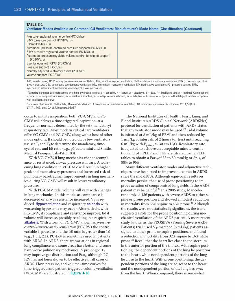
© Jones & Bartlett Learning, LLCNOT FOR SALE OR DISTRIBUTION
© Jones & Bartlett Learning, LLCNOT FOR SALE OR DISTRIBUTION
© Jones & Bartlett Learning, LLCNOT FOR SALE OR DISTRIBUTION
© Jones & Bartlett Learning, LLCNOT FOR SALE OR DISTRIBUTION
© Jones & Bartlett Learning, LLCNOT FOR SALE OR DISTRIBUTION
© Jones & Bartlett Learning, LLCNOT FOR SALE OR DISTRIBUTION
© Jones & Bartlett Learning, LLCNOT FOR SALE OR DISTRIBUTION
© Jones & Bartlett Learning, LLCNOT FOR SALE OR DISTRIBUTION
© Jones & Bartlett Learning, LLCNOT FOR SALE OR DISTRIBUTION
© Jones & Bartlett Learning, LLCNOT FOR SALE OR DISTRIBUTION
© Jones & Bartlett Learning, LLCNOT FOR SALE OR DISTRIBUTION
© Jones & Bartlett Learning, LLCNOT FOR SALE OR DISTRIBUTION
© Jones & Bartlett Learning, LLCNOT FOR SALE OR DISTRIBUTION
© Jones & Bartlett Learning, LLCNOT FOR SALE OR DISTRIBUTION
© Jones & Bartlett Learning, LLCNOT FOR SALE OR DISTRIBUTION
© Jones & Bartlett Learning, LLCNOT FOR SALE OR DISTRIBUTION
© Jones & Bartlett Learning, LLCNOT FOR SALE OR DISTRIBUTION
© Jones & Bartlett Learning, LLCNOT FOR SALE OR DISTRIBUTION
© Jones & Bartlett Learning, LLCNOT FOR SALE OR DISTRIBUTION
© Jones & Bartlett Learning, LLCNOT FOR SALE OR DISTRIBUTION
120 CHAPTER 3 Principles of Mechanical Ventilation
occur to initiate inspiration, both VC-CMV and PC-CMV will deliver a time-triggered inspiration, at a frequency normally determined by the set (mandatory) respiratory rate. Most modern critical care ventilators offer VC-CMV and PC-CMV, along with a host of other mode options. It should be noted that a few ventilators use set TI and TE to determine the mandatory, time-cycled rate and I:E ratio (e.g., pNeuton mini and Smiths Medical Pneupac babyPAC 100).
With VC-CMV, if lung mechanics change (compli-ance or resistance), airway pressure will vary. A wors-ening lung condition in VC-CMV will result in higher peak and mean airway pressures and increased risk of pulmonary barotrauma. Improvements in lung mechan-ics during VC-CMV will result in lower ventilatory pressures.
With PC-CMV, tidal volume will vary with changes in lung mechanics. In this mode, as compliance is decreased or airway resistance increased, VT is re-duced. Hypoventilation and respiratory acidosis with worsening hypoxemia may occur. Alternatively, with PC-CMV, if compliance and resistance improve, tidal volume will increase, possibly resulting in a respiratory alkalosis. With a form of PC-CMV known as pressure-control–inverse-ratio ventilation (PC-IRV) the control variable is pressure and the I:E ratio is greater than 1:1 (e.g., 1.5:1, 2:1). PC-IRV is sometimes used in patients with ARDS. In ARDS, there are variations in regional lung compliance and some areas have better and some have worse pulmonary mechanics. A prolonged TI may improve gas distribution and Pao2, although PC-IRV has not been shown to be effective in all cases of ARDS. Flow, pressure, and volume–time curves for time-triggered and patient-triggered volume ventilation (VC-CMV) are illustrated in Figure 3-18.
The National Institutes of Health Heart, Lung, and Blood Institute’s ARDS Clinical Network (ARDSNet) protocol for ventilation of patients with ARDS states that any ventilator mode may be used.19 Tidal volume is initiated at 8 mL/kg of PBW and then reduced by 1 mL/kg at intervals of 2 hours (or less) until reaching 6 mL/kg with Pplateau ≤ 30 cm H2O. Respiratory rate is adjusted to achieve an acceptable minute ventila-tion and pH. PEEP and Fio2 are titrated using PEEP tables to obtain a Pao2 of 55 to 80 mmHg or Spo2 of 88% to 95%.
Many different ventilator modes and adjunctive tech-niques have been tried to improve outcomes in ARDS since the mid-1970s. Although equivocal results on mortality persist, the use of prone positioning to im-prove aeration of compromised lung fields in the ARDS patient may be helpful.20 In a 2006 study, Mancebo randomized 136 patients with severe ARDS to either su-pine or prone position and showed a modest reduction in mortality from 58% supine to 43% prone.21 Although the results were not statistically significant, the trend suggested a role for the prone positioning during me-chanical ventilation of the ARDS patient. A more recent study, known as the PROSEVA (Proning Severe ARDS Patients) trial, used VT-matched (6 mL/kg) patients as-signed to either prone or supine positions, and found a reduction in mortality from 32% supine to 16% while prone.22 Recall that the heart lies close to the sternum in the anterior portion of the thorax. With supine posi-tioning, the dependent portions of the lung lie posterior to the heart, while nondependent portions of the lung lie close to the heart. With prone positioning, the de-pendent portions of the lung are adjacent to the heart and the nondependent portion of the lung lies away from the heart. When compared, there is somewhat
TABLE 3-1 Ventilator Modes Available on Common ICU Ventilators: Manufacturer’s Mode Name (Classification) (Continued)
Pressure-regulated volume control (PC-CMVa)SIMV (pressure control) (PC-IMVs, s)BiVent (PC-IMVs, s)Automode (pressure control to pressure support) (PC-IMVs, s)SIMV pressure-regulated volume control (PC-IMVa, s)Automode (pressure-regulated volume control to volume support)
(PC-IMVa, a)Spontaneous with CPAP (PC-CSVs)Pressure support (PC-CSVs)Neurally adjusted ventilatory assist (PC-CSVr)Volume support (PC-CSVa)
A/C, assist-control; APRV, airway pressure release ventilation; ASV, adaptive support ventilation; CMV, continuous mandatory ventilation; CPAP, continuous positive airway pressure; CSV, continuous spontaneous ventilation; IMV, intermittent mandatory ventilation; NIV, noninvasive ventilation; PC, pressure control; SIMV, synchonized intermittent mechanical ventilation; VC, volume control.
*Targeting schemes are represented by single lowercase letters: s = set-point, r = servo, a = adaptive, d = dual, i = intelligent, and o = optimal. Combinations include: sr = set-point with servo, da = dual with adaptive, as = adaptive with set-point, ar = adaptive with servo, oi = optimal with intelligent, and oir = optimal with intelligent and servo.
Data from Chatburn RL, El-Khatib M, Mireles-Cabodevila E. A taxonomy for mechanical ventilation: 10 fundamental maxims. Respir Care. 2014;59(11): 1747–1763. doi:10.4187/respcare.03057.
9781284139860_CH03_095_154.indd 120 21/02/19 5:37 PM
© Jones & Bartlett Learning, LLC. NOT FOR SALE OR DISTRIBUTION.

© Jones & Bartlett Learning, LLCNOT FOR SALE OR DISTRIBUTION
© Jones & Bartlett Learning, LLCNOT FOR SALE OR DISTRIBUTION
© Jones & Bartlett Learning, LLCNOT FOR SALE OR DISTRIBUTION
© Jones & Bartlett Learning, LLCNOT FOR SALE OR DISTRIBUTION
© Jones & Bartlett Learning, LLCNOT FOR SALE OR DISTRIBUTION
© Jones & Bartlett Learning, LLCNOT FOR SALE OR DISTRIBUTION
© Jones & Bartlett Learning, LLCNOT FOR SALE OR DISTRIBUTION
© Jones & Bartlett Learning, LLCNOT FOR SALE OR DISTRIBUTION
© Jones & Bartlett Learning, LLCNOT FOR SALE OR DISTRIBUTION
© Jones & Bartlett Learning, LLCNOT FOR SALE OR DISTRIBUTION
© Jones & Bartlett Learning, LLCNOT FOR SALE OR DISTRIBUTION
© Jones & Bartlett Learning, LLCNOT FOR SALE OR DISTRIBUTION
© Jones & Bartlett Learning, LLCNOT FOR SALE OR DISTRIBUTION
© Jones & Bartlett Learning, LLCNOT FOR SALE OR DISTRIBUTION
© Jones & Bartlett Learning, LLCNOT FOR SALE OR DISTRIBUTION
© Jones & Bartlett Learning, LLCNOT FOR SALE OR DISTRIBUTION
© Jones & Bartlett Learning, LLCNOT FOR SALE OR DISTRIBUTION
© Jones & Bartlett Learning, LLCNOT FOR SALE OR DISTRIBUTION
© Jones & Bartlett Learning, LLCNOT FOR SALE OR DISTRIBUTION
© Jones & Bartlett Learning, LLCNOT FOR SALE OR DISTRIBUTION
Ventilator Modes 121
FIgURE 3-18 Flow, Pressure, and Volume–Time Curves for Time-Triggered and Patient-Triggered Volume Ventilation (VC-CMV). (A) Time-triggered volume ventilation (VC-CMV), sometimes referred to as controlled ventilation. (B) Patient-triggered volume ventilation (VC-CMV), sometimes referred to as assist-control ventilation.From Waugh JB, Deshpande VM, Brown MK, Harwood R. Rapid Interpretation of Ventilator Waveforms. 2nd ed. Upper Saddle River, NJ: Prentice Hall; 2006.
Flo
w (
L/m
in)
Pre
ssur
e (c
m H
2O)
Vol
ume
(cc)
800
600
400
200
00 2 4 6 8
Time (seconds)
10 12 141 3 5 7 9 11 13
–40
–20
0
20
16
12
8
4
0
40
60
Flo
w (
L/m
in)
Pre
ssur
e (c
m H
2O)
Vol
ume
(cc)
800
600
400
200
02 4 6 8
Time (seconds)
10 12 141 3 5 7 9 11 13
–40
–20
0
20
16
12
8
4
0
40
60
(A)
(B)
9781284139860_CH03_095_154.indd 121 21/02/19 5:37 PM
© Jones & Bartlett Learning, LLC. NOT FOR SALE OR DISTRIBUTION.
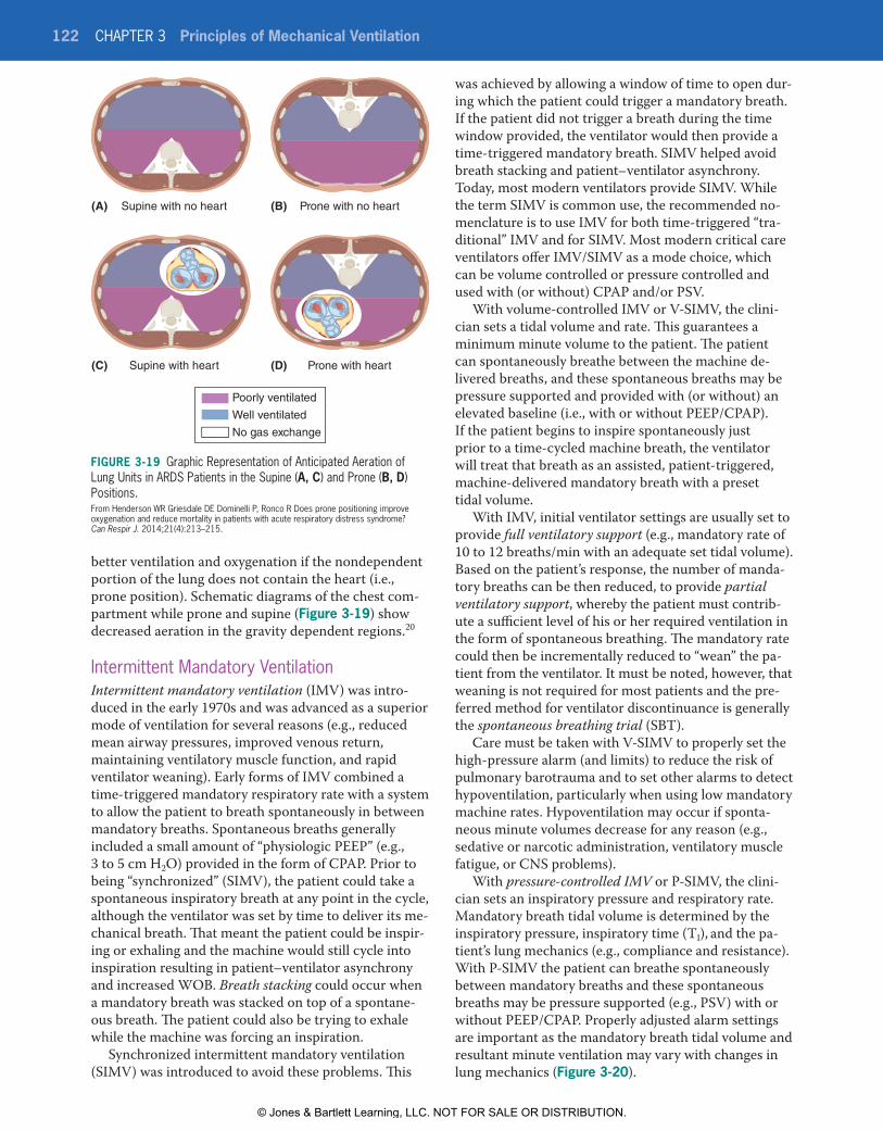
© Jones & Bartlett Learning, LLCNOT FOR SALE OR DISTRIBUTION
© Jones & Bartlett Learning, LLCNOT FOR SALE OR DISTRIBUTION
© Jones & Bartlett Learning, LLCNOT FOR SALE OR DISTRIBUTION
© Jones & Bartlett Learning, LLCNOT FOR SALE OR DISTRIBUTION
© Jones & Bartlett Learning, LLCNOT FOR SALE OR DISTRIBUTION
© Jones & Bartlett Learning, LLCNOT FOR SALE OR DISTRIBUTION
© Jones & Bartlett Learning, LLCNOT FOR SALE OR DISTRIBUTION
© Jones & Bartlett Learning, LLCNOT FOR SALE OR DISTRIBUTION
© Jones & Bartlett Learning, LLCNOT FOR SALE OR DISTRIBUTION
© Jones & Bartlett Learning, LLCNOT FOR SALE OR DISTRIBUTION
© Jones & Bartlett Learning, LLCNOT FOR SALE OR DISTRIBUTION
© Jones & Bartlett Learning, LLCNOT FOR SALE OR DISTRIBUTION
© Jones & Bartlett Learning, LLCNOT FOR SALE OR DISTRIBUTION
© Jones & Bartlett Learning, LLCNOT FOR SALE OR DISTRIBUTION
© Jones & Bartlett Learning, LLCNOT FOR SALE OR DISTRIBUTION
© Jones & Bartlett Learning, LLCNOT FOR SALE OR DISTRIBUTION
© Jones & Bartlett Learning, LLCNOT FOR SALE OR DISTRIBUTION
© Jones & Bartlett Learning, LLCNOT FOR SALE OR DISTRIBUTION
© Jones & Bartlett Learning, LLCNOT FOR SALE OR DISTRIBUTION
© Jones & Bartlett Learning, LLCNOT FOR SALE OR DISTRIBUTION
122 CHAPTER 3 Principles of Mechanical Ventilation
better ventilation and oxygenation if the nondependent portion of the lung does not contain the heart (i.e., prone position). Schematic diagrams of the chest com-partment while prone and supine (Figure 3-19) show decreased aeration in the gravity dependent regions.20
Intermittent Mandatory VentilationIntermittent mandatory ventilation (IMV) was intro-duced in the early 1970s and was advanced as a superior mode of ventilation for several reasons (e.g., reduced mean airway pressures, improved venous return, maintaining ventilatory muscle function, and rapid ventilator weaning). Early forms of IMV combined a time-triggered mandatory respiratory rate with a system to allow the patient to breath spontaneously in between mandatory breaths. Spontaneous breaths generally included a small amount of “physiologic PEEP” (e.g., 3 to 5 cm H2O) provided in the form of CPAP. Prior to being “synchronized” (SIMV), the patient could take a spontaneous inspiratory breath at any point in the cycle, although the ventilator was set by time to deliver its me-chanical breath. That meant the patient could be inspir-ing or exhaling and the machine would still cycle into inspiration resulting in patient–ventilator asynchrony and increased WOB. Breath stacking could occur when a mandatory breath was stacked on top of a spontane-ous breath. The patient could also be trying to exhale while the machine was forcing an inspiration.
Synchronized intermittent mandatory ventilation (SIMV) was introduced to avoid these problems. This
was achieved by allowing a window of time to open dur-ing which the patient could trigger a mandatory breath. If the patient did not trigger a breath during the time window provided, the ventilator would then provide a time-triggered mandatory breath. SIMV helped avoid breath stacking and patient–ventilator asynchrony. Today, most modern ventilators provide SIMV. While the term SIMV is common use, the recommended no-menclature is to use IMV for both time-triggered “tra-ditional” IMV and for SIMV. Most modern critical care ventilators offer IMV/SIMV as a mode choice, which can be volume controlled or pressure controlled and used with (or without) CPAP and/or PSV.
With volume-controlled IMV or V-SIMV, the clini-cian sets a tidal volume and rate. This guarantees a minimum minute volume to the patient. The patient can spontaneously breathe between the machine de-livered breaths, and these spontaneous breaths may be pressure supported and provided with (or without) an elevated baseline (i.e., with or without PEEP/CPAP). If the patient begins to inspire spontaneously just prior to a time-cycled machine breath, the ventilator will treat that breath as an assisted, patient-triggered, machine-delivered mandatory breath with a preset tidal volume.
With IMV, initial ventilator settings are usually set to provide full ventilatory support (e.g., mandatory rate of 10 to 12 breaths/min with an adequate set tidal volume). Based on the patient’s response, the number of manda-tory breaths can be then reduced, to provide partial ventilatory support, whereby the patient must contrib-ute a sufficient level of his or her required ventilation in the form of spontaneous breathing. The mandatory rate could then be incrementally reduced to “wean” the pa-tient from the ventilator. It must be noted, however, that weaning is not required for most patients and the pre-ferred method for ventilator discontinuance is generally the spontaneous breathing trial (SBT).
Care must be taken with V-SIMV to properly set the high-pressure alarm (and limits) to reduce the risk of pulmonary barotrauma and to set other alarms to detect hypoventilation, particularly when using low mandatory machine rates. Hypoventilation may occur if sponta-neous minute volumes decrease for any reason (e.g., sedative or narcotic administration, ventilatory muscle fatigue, or CNS problems).
With pressure-controlled IMV or P-SIMV, the clini-cian sets an inspiratory pressure and respiratory rate. Mandatory breath tidal volume is determined by the inspiratory pressure, inspiratory time (TI), and the pa-tient’s lung mechanics (e.g., compliance and resistance). With P-SIMV the patient can breathe spontaneously between mandatory breaths and these spontaneous breaths may be pressure supported (e.g., PSV) with or without PEEP/CPAP. Properly adjusted alarm settings are important as the mandatory breath tidal volume and resultant minute ventilation may vary with changes in lung mechanics (Figure 3-20).
Figure 3-19 Graphic Representation of Anticipated Aeration of Lung Units in ARDS Patients in the Supine (A, C) and Prone (B, D) Positions.From Henderson WR Griesdale DE Dominelli P, Ronco R Does prone positioning improve oxygenation and reduce mortality in patients with acute respiratory distress syndrome? Can Respir J. 2014;21(4):213–215.
Supine with no heart(A) (B)
(C) (D)Supine with heart
Prone with no heart
Prone with heart
Poorly ventilated
Well ventilated
No gas exchange
9781284139860_CH03_095_154.indd 122 28/02/19 7:28 AM
© Jones & Bartlett Learning, LLC. NOT FOR SALE OR DISTRIBUTION.

© Jones & Bartlett Learning, LLCNOT FOR SALE OR DISTRIBUTION
© Jones & Bartlett Learning, LLCNOT FOR SALE OR DISTRIBUTION
© Jones & Bartlett Learning, LLCNOT FOR SALE OR DISTRIBUTION
© Jones & Bartlett Learning, LLCNOT FOR SALE OR DISTRIBUTION
© Jones & Bartlett Learning, LLCNOT FOR SALE OR DISTRIBUTION
© Jones & Bartlett Learning, LLCNOT FOR SALE OR DISTRIBUTION
© Jones & Bartlett Learning, LLCNOT FOR SALE OR DISTRIBUTION
© Jones & Bartlett Learning, LLCNOT FOR SALE OR DISTRIBUTION
© Jones & Bartlett Learning, LLCNOT FOR SALE OR DISTRIBUTION
© Jones & Bartlett Learning, LLCNOT FOR SALE OR DISTRIBUTION
© Jones & Bartlett Learning, LLCNOT FOR SALE OR DISTRIBUTION
© Jones & Bartlett Learning, LLCNOT FOR SALE OR DISTRIBUTION
© Jones & Bartlett Learning, LLCNOT FOR SALE OR DISTRIBUTION
© Jones & Bartlett Learning, LLCNOT FOR SALE OR DISTRIBUTION
© Jones & Bartlett Learning, LLCNOT FOR SALE OR DISTRIBUTION
© Jones & Bartlett Learning, LLCNOT FOR SALE OR DISTRIBUTION
© Jones & Bartlett Learning, LLCNOT FOR SALE OR DISTRIBUTION
© Jones & Bartlett Learning, LLCNOT FOR SALE OR DISTRIBUTION
© Jones & Bartlett Learning, LLCNOT FOR SALE OR DISTRIBUTION
© Jones & Bartlett Learning, LLCNOT FOR SALE OR DISTRIBUTION
Ventilator Modes 123
FIgURE 3-20 Graphic Display of the Differences Between VC-SIMV (A) and PC-SIMV (B). In A, the tidal volume is set by the respiratory therapist and does not change resulting in pressure variations with changes in lung mechanics (as noted in the second machine-delivered breath). In B, the pressure is set by the respiratory therapist and VT will vary with changes in lung mechanics.From Tobin MJ. Principles and Practice of Mechanical Ventilation. 2nd ed. New York, NY: McGraw-Hill; 2006: 68−69.
Flo
w (
L/m
in)
Pre
ssur
e (c
m H
2O)
Vol
ume
(mL)
600
400
200
00 2 4 6 8
Time (seconds)
10 12 14
–80
–40
0
20
16
12
8
4
0
40
80
Flo
w (
L/m
in)
Pre
ssur
e (c
m H
2O)
Vol
ume
(mL)
600
400
200
00 2 4 6 8
Time (seconds)
10 12 14
1 3 5 7 9 11 13
1 3 5 7 9 11 13
–80
–40
0
20
16
12
8
4
0
40
80
(A)
(B)
9781284139860_CH03_095_154.indd 123 21/02/19 5:37 PM
© Jones & Bartlett Learning, LLC. NOT FOR SALE OR DISTRIBUTION.

© Jones & Bartlett Learning, LLCNOT FOR SALE OR DISTRIBUTION
© Jones & Bartlett Learning, LLCNOT FOR SALE OR DISTRIBUTION
© Jones & Bartlett Learning, LLCNOT FOR SALE OR DISTRIBUTION
© Jones & Bartlett Learning, LLCNOT FOR SALE OR DISTRIBUTION
© Jones & Bartlett Learning, LLCNOT FOR SALE OR DISTRIBUTION
© Jones & Bartlett Learning, LLCNOT FOR SALE OR DISTRIBUTION
© Jones & Bartlett Learning, LLCNOT FOR SALE OR DISTRIBUTION
© Jones & Bartlett Learning, LLCNOT FOR SALE OR DISTRIBUTION
© Jones & Bartlett Learning, LLCNOT FOR SALE OR DISTRIBUTION
© Jones & Bartlett Learning, LLCNOT FOR SALE OR DISTRIBUTION
© Jones & Bartlett Learning, LLCNOT FOR SALE OR DISTRIBUTION
© Jones & Bartlett Learning, LLCNOT FOR SALE OR DISTRIBUTION
© Jones & Bartlett Learning, LLCNOT FOR SALE OR DISTRIBUTION
© Jones & Bartlett Learning, LLCNOT FOR SALE OR DISTRIBUTION
© Jones & Bartlett Learning, LLCNOT FOR SALE OR DISTRIBUTION
© Jones & Bartlett Learning, LLCNOT FOR SALE OR DISTRIBUTION
© Jones & Bartlett Learning, LLCNOT FOR SALE OR DISTRIBUTION
© Jones & Bartlett Learning, LLCNOT FOR SALE OR DISTRIBUTION
© Jones & Bartlett Learning, LLCNOT FOR SALE OR DISTRIBUTION
© Jones & Bartlett Learning, LLCNOT FOR SALE OR DISTRIBUTION
124 CHAPTER 3 Principles of Mechanical Ventilation
Positive End-Expiratory PressurePositive end-expiratory pressure (PEEP) is intended to splint the airways open, improve the distribution of gas, and prevent alveolar collapse. PEEP increases functional residual capacity (FRC) and may improve oxygenation in patients with acute restrictive pulmonary disease (e.g., ARDS, pneumonia, and atelectasis). PEEP provides an elevated baseline pressure during expiration. Endo-tracheal intubation can result in a small reduction in patients’ FRC due to the loss of normal glottic function. A small amount (3 to 5 cm H2O) of “physiologic PEEP” has been suggested for most patients, to balance the loss of “natural PEEP” following endotracheal intubation. PEEP may reduce the incidence of ventilator-associated pneumonia and prevent the development of hypoxemia.
PEEP applied intentionally for therapeutic purposes is known as extrinsic PEEP or applied PEEP. Uninten-tional PEEP due to incomplete airway emptying during expiration is known as intrinsic PEEP, “inadvertent PEEP,” “accidental PEEP,” “ghost PEEP,” or “autoPEEP.” Intrinsic PEEP causes pulmonary overinflation and can cause difficulty for the patient in triggering the ventila-tor. Steps to correct for autoPEEP should be taken, and may include using smaller tidal volumes, decreasing inspiratory time, increasing expiratory time, reducing mandatory respiratory rate, and the application of a small amount of extrinsic PEEP, usually less than the measured autoPEEP value (e.g., 50% of autoPEEP level). The use of extrinsic PEEP to balance autoPEEP probably should be limited to patients that have trouble trigger-ing the ventilator.
PEEP levels in the range of 5 to 20 cm H2O are often used to improve oxygenation and reduce the harmful effects of cyclic alveolar collapse and re-inflation that can occur with ARDS in the absence of PEEP. Improve-ment in patients’ Pao2/Fio2 ratio with PEEP is associ-ated with decreased mortality in ARDS. Optimal PEEP levels have not been definitively identified, and many methods of applying PEEP have been advocated. These include using the least PEEP necessary to achieve an ac-ceptable Fio2 (aka minimal PEEP), titrating PEEP based on oxygen delivery, compliance-titrated PEEP, and use of pressure–volume curves to set the optimum PEEP level. The ARDS Clinical Network suggests use of an Fio2–PEEP table to adjust PEEP levels.
Viewing the patient’s pressure–volume curves during mechanical ventilation can be helpful in the determi-nation of an appropriate PEEP setting. When zero or sub-therapeutic PEEP is applied in patients with ARDS, the small airways may collapse during expiration and re-inflate during inspiration. Each inspired breath may result in shearing forces or wall stress. This could lead to an increased inflammatory response and worsen-ing of overall lung condition. With subtherapeutic PEEP, a slow flow (e.g., inspiratory flow < 10 L/min) pressure–volume curve may indicate low compliance
at the initiation of the mandatory ventilator breath, fol-lowed by a shift in the curve as compliance improves. The point at which the curve shifts is known as the lower inflection point (LIP). Using this method, PEEP is set 2 cm H2O above the LIP. It must be noted that not all ARDS patients exhibit an LIP.
Lung Recruitment Maneuvers and PEEPLung recruitment maneuvers are sometimes applied in patients with ARDS to improve V/Q and reduce shunt-ing. One method involves the use of pressure-control ventilation in which PEEP is set in the range of 20 to 25 cm H2O and the pressure-control level is set about 15 cm H2O above PEEP for a period of 2 to 3 minutes. This is followed by a decremental PEEP study to identify the PEEP level at which compliance is at its highest value.
There are differences in mechanical ventilators when setting PEEP during pressure-control ventilation and the manuals for each ventilator should be consulted prior to initiation of a pressure-controlled mode. PEEP may contribute to pulmonary barotrauma and alveolar overdistention resulting in ventilator-associated lung injury. To avoid this, Pplateau should be kept ≤ 30 cm H2O. It should be noted that use of PEEP in severely hypoxemic patients with unilateral or focal lung disease (focal pneumonia) may be ineffective. PEEP should also be used very cautiously in patients with obstructive lung disease, hemodynamic instability, or increased ICP.
Fick’s law applies to diffusion of gas across the alveo-lar capillary (AC) membrane, which is determined by Pao2 and the AC surface area; PEEP increases the sur-face area for gas exchange. Respiratory care clinicians use combinations of Fio2 and PEEP to achieve target Pao2 and Sao2 values at a “safe” Fio2 (generally ≤ 0.50 to 0.60). PEEP contributes directly to the mean airway pressure, and when increases in PEEP are considered, the effects on venous return and cardiac output should be considered. When adjusting Fio2 and PEEP, there may be necessary tradeoffs between the hazards of O2 toxicity versus the possibility of ventilator-associated lung injury due to higher PEEP. Through research conducted and reported in the ARDSNet trials, it was noted that more severe ARDS patients may benefit from more aggressive PEEP levels (12 to 24 cm H2O) while mild cases of ARDS generally show improved oxygen-ation with lower PEEP levels. Protocols have reduced ventilator-induced lung injury and problems associated with pulmonary O2 toxicity.
To summarize, PEEP can often be very useful in improving oxygenation in patients with acute, se-vere restrictive lung disease (e.g., ARDS). PEEP in-creases mean airway and intrathoracic pressure and may promote the development of barotrauma and ventilator-associated lung injury (VALI), and reduce venous return, cardiac output, and systemic blood
9781284139860_CH03_095_154.indd 124 21/02/19 5:37 PM
© Jones & Bartlett Learning, LLC. NOT FOR SALE OR DISTRIBUTION.

© Jones & Bartlett Learning, LLCNOT FOR SALE OR DISTRIBUTION
© Jones & Bartlett Learning, LLCNOT FOR SALE OR DISTRIBUTION
© Jones & Bartlett Learning, LLCNOT FOR SALE OR DISTRIBUTION
© Jones & Bartlett Learning, LLCNOT FOR SALE OR DISTRIBUTION
© Jones & Bartlett Learning, LLCNOT FOR SALE OR DISTRIBUTION
© Jones & Bartlett Learning, LLCNOT FOR SALE OR DISTRIBUTION
© Jones & Bartlett Learning, LLCNOT FOR SALE OR DISTRIBUTION
© Jones & Bartlett Learning, LLCNOT FOR SALE OR DISTRIBUTION
© Jones & Bartlett Learning, LLCNOT FOR SALE OR DISTRIBUTION
© Jones & Bartlett Learning, LLCNOT FOR SALE OR DISTRIBUTION
© Jones & Bartlett Learning, LLCNOT FOR SALE OR DISTRIBUTION
© Jones & Bartlett Learning, LLCNOT FOR SALE OR DISTRIBUTION
© Jones & Bartlett Learning, LLCNOT FOR SALE OR DISTRIBUTION
© Jones & Bartlett Learning, LLCNOT FOR SALE OR DISTRIBUTION
© Jones & Bartlett Learning, LLCNOT FOR SALE OR DISTRIBUTION
© Jones & Bartlett Learning, LLCNOT FOR SALE OR DISTRIBUTION
© Jones & Bartlett Learning, LLCNOT FOR SALE OR DISTRIBUTION
© Jones & Bartlett Learning, LLCNOT FOR SALE OR DISTRIBUTION
© Jones & Bartlett Learning, LLCNOT FOR SALE OR DISTRIBUTION
© Jones & Bartlett Learning, LLCNOT FOR SALE OR DISTRIBUTION
Ventilator Modes 125
FIgURE 3-21 Comparison of the Pressure–Time Curves for Spontaneous Breathing and CPAP. Spontaneous breathing is measured at an atmospheric baseline pressure (0 cm H2O) and CPAP is measured at an elevated baseline pressure of +5 cm H2O.
Pre
ssur
e (c
m H
2O)
Time
CPAPBaseline = +5
Spontaneous breathingBaseline = 0
0
+5
+
–
pressure. PEEP can increase ICP, and this should be kept in mind when treating patients with increased ICP (e.g., head trauma).
Continuous Positive Airway PressureContinuous positive airway pressure (CPAP) describes spontaneous breathing at an elevated baseline pres-sure. Like PEEP, CPAP increases mean airway pressure and mean intrathoracic pressure and FRC. In the ICU, CPAP may be provided through the ventilator, or inde-pendently using a high-flow, blended and humidified gas source and a PEEP valve. Acute care uses of CPAP include improving oxygenation in patients with respira-tory failure, prevention of postoperative atelectasis, and treatment of cardiogenic pulmonary edema. A number of small, portable CPAP machines have also been de-veloped for in-home use to treat obstructive sleep apnea (OSA); these units are sometimes employed in the acute care setting for patients with OSA.
With CPAP, the patient both initiates and termi-nates an inspiration. Put another way, CPAP provides patient-triggered and patient-cycled breaths. CPAP can be provided as a standalone mode (i.e., continuous spontaneous ventilation [CSV]) or in combination with pressure support. CPAP may also be used with IMV. CPAP may be provided by mask or via a cuffed endotra-cheal or tracheostomy tube.
With CPAP, the breathing circuit pressure is elevated during inspiration and expiration. Thus, CPAP pro-vides a form of inspiratory pressure augmentation that may reduce the inspiratory WOB during spontaneous breathing. This may be helpful in patients undergoing spontaneous breathing trials (SBTs) leading to extu-bation. Like PEEP, CPAP’s elevated expiratory pres-sure increases FRC and the lung surface area for gas exchange. Thus, CPAP may improve oxygenation and help prevent alveolar collapse and atelectasis. As noted, CPAP increases mean airway pressure and intrathoracic pressure; excessive levels may decrease venous return, decrease cardiac output, and decrease blood pressure. Figure 3-21 compares pressure–time curves for base-line spontaneous breathing and CPAP. As with PEEP,
CPAP should be used cautiously in patients with ob-structive lung disease and in those with hemodynamic instability or elevated ICP.
CPAP and Obstructive Sleep ApneaObstructive sleep apnea (OSA) is defined as the ces-sation of airflow for ≥ 10 seconds with evidence of sustained inspiratory effort. Noninvasive CPAP deliv-ered by oral or nasal mask at pressures in the range of 4 to 20 cm H2O is the preferred treatment for OSA. In this range, CPAP splints the soft tissue of the up-per airway and prevents collapse, airway obstruction, and apnea. CPAP is also indicated for the treatment of clinically significant obstructive hypopneas. For OSA, the CPAP pressure should be titrated in the sleep laboratory for any patient with multiple comor-bidities, significant cardiac history, or morbid obesity. Patients with high BMI may require very high levels of CPAP to control OSA. If CPAP of 20 cm H2O fails to adequately control OSA, BiPAP may be employed. BiPAP combines inspiratory positive airway and expiratory positive airway pressure (EPAP), which is titrated to a maximum setting of 30/25 cm H2O (IPAP/EPAP). Mask leak, patient intolerance of pres-sure, and aerophagia (air swallowing) are problems as-sociated with high positive airway pressures.
In addition to CPAP, other strategies for OSA man-agement include sleeping with the head of the bed el-evated, dental appliances, and weight loss (e.g., bariatric surgery). Other techniques that have been employed with varying degrees of success include autotitrating CPAP or autotitrating positive airway pressure (APAP) and adaptive servo-ventilation (ASV) with CPAP. Autotitrating CPAP varies the airway pressure during the night based on specific algorithms. ASV is a closed-loop form of ventilation that uses breath-to-breath anal-ysis to target a desired minute volume and minimize WOB. ASV may be useful in patients with abnormal breathing patterns and complex sleep apnea. The major problem associated with CPAP and OSA treatment is patient compliance. Other complications associated with CPAP are highlighted in Box 3-8.
Recruitment Maneuvers with CPAPVery high levels of CPAP for brief periods of time (e.g., 40 cm H2O for 40 seconds) have been suggested as a part of recruitment maneuvers to open collapsed alveoli in patients with ARDS. Such recruitment maneuvers should not be routinely employed, although some pa-tients may benefit.
Noninvasive VentilationA commonly employed version of noninvasive venti-lation (NIV) uses bilevel airway pressure (BiPAP) to provide ventilatory support. BiPAP combines IPAP with
9781284139860_CH03_095_154.indd 125 21/02/19 5:37 PM
© Jones & Bartlett Learning, LLC. NOT FOR SALE OR DISTRIBUTION.

© Jones & Bartlett Learning, LLCNOT FOR SALE OR DISTRIBUTION
© Jones & Bartlett Learning, LLCNOT FOR SALE OR DISTRIBUTION
© Jones & Bartlett Learning, LLCNOT FOR SALE OR DISTRIBUTION
© Jones & Bartlett Learning, LLCNOT FOR SALE OR DISTRIBUTION
© Jones & Bartlett Learning, LLCNOT FOR SALE OR DISTRIBUTION
© Jones & Bartlett Learning, LLCNOT FOR SALE OR DISTRIBUTION
© Jones & Bartlett Learning, LLCNOT FOR SALE OR DISTRIBUTION
© Jones & Bartlett Learning, LLCNOT FOR SALE OR DISTRIBUTION
© Jones & Bartlett Learning, LLCNOT FOR SALE OR DISTRIBUTION
© Jones & Bartlett Learning, LLCNOT FOR SALE OR DISTRIBUTION
© Jones & Bartlett Learning, LLCNOT FOR SALE OR DISTRIBUTION
© Jones & Bartlett Learning, LLCNOT FOR SALE OR DISTRIBUTION
© Jones & Bartlett Learning, LLCNOT FOR SALE OR DISTRIBUTION
© Jones & Bartlett Learning, LLCNOT FOR SALE OR DISTRIBUTION
© Jones & Bartlett Learning, LLCNOT FOR SALE OR DISTRIBUTION
© Jones & Bartlett Learning, LLCNOT FOR SALE OR DISTRIBUTION
© Jones & Bartlett Learning, LLCNOT FOR SALE OR DISTRIBUTION
© Jones & Bartlett Learning, LLCNOT FOR SALE OR DISTRIBUTION
© Jones & Bartlett Learning, LLCNOT FOR SALE OR DISTRIBUTION
© Jones & Bartlett Learning, LLCNOT FOR SALE OR DISTRIBUTION
126 CHAPTER 3 Principles of Mechanical Ventilation
EPAP. With BiPAP, the patient typically initiates and terminates inspiration; however, inspiratory pressure augmentation is provided (i.e., IPAP) and expiratory pressure maintains an elevated baseline (i.e., EPAP).
BiPAP is typically applied using an oral or nasal mask. EPAP is initially set in the range of 5 to 10 cm H2O and titrated to achieve acceptable oxygenation while minimizing patient discomfort. IPAP is set to achieve an inspiratory pressure of 5 to 15 cm H2O above EPAP and titrated to achieve adequate ventilation and reduced WOB.
NIV may be especially useful in patients with acute respiratory failure due to COPD exacerbation to reduce the need for endotracheal intubation, decrease length of hospital stay, and decrease mortality. NIV is also indicated in patients at high risk for extubation failure, and extubation to NIV has been recommended in this group. NIV may be useful in other acute and chronic conditions, as further described in Chapter 10. NIV has
not been shown to be helpful for patients with acute hy-poxemic respiratory failure (e.g., ARDS).
Pressure-Support VentilationPressure-support ventilation (PSV) provides for patient-triggered, pressure-limited, flow-cycled venti-lation. PSV may be further described as spontaneous breathing with inspiratory pressure augmentation; expiration may include the addition of an elevated baseline (i.e., PEEP/CPAP). PSV allows the patient to achieve a given spontaneous tidal volume with less effort. PSV overcomes the resistance to ventilation caused by ventilator circuits and artificial airways. PSV may enhance weaning. PSV also allows the clinician to adjust the ventilatory workload of the patient. PSV may be used as a standalone mode or in conjunction with IMV/SIMV.
Modest levels of pressure support (e.g., 5 to 15 cm H2O) can be used to overcome the imposed WOB due to endotracheal or tracheostomy tubes. Higher levels of PSV (e.g., 15 to 25 cm H2O) further reduce the patient’s WOB. Low levels of PSV (5 to 8 cm H2O) are often em-ployed in conjunction with CPAP during spontaneous breathing trials (SBTs) to evaluate readiness for ventila-tor discontinuance and extubation.
With PSV, patients can control their respiratory rate and inspiratory flows, times, and volumes. As a patient-triggered mode, pressure support should not be used in patients with unstable ventilatory drives or pe-riods of apnea. High and low VE alarms should be set to help detect hypo- or hyperventilation.
Choice of pressure-support pressure level depends on the specific goal. Common goals include:
■■ Reducing or eliminating the imposed work of breathing (WOBI) associated with spontaneous breaths in between mandatory breaths in the IMV/SIMV mode. PSV values needed to eliminate WOBI will vary depending on the patient’s venti-latory pattern and endotracheal or tracheostomy tube diameter but are generally the range of 5 to 15 cm H2O.
■■ Reducing or eliminating the imposed work of breathing (WOBI) associated with spontane-ous breaths during a spontaneous breathing trial (SBT). Here, PSV values needed will also vary depending on the patient’s ventilatory pattern and endotracheal/tracheostomy tube diameter. Cur-rent guidelines suggest initiating PSV at 5 to 8 cm H2O during SBTs.
■■ Providing a relatively high level of ventilatory support that may improve patient–ventilator syn-chrony and comfort and reduce the WOB. PSV used in this fashion is adjusted to achieve an ad-equate tidal volume (4 to 8 mL/kg IBW) usually at a reasonable spontaneous respiratory rate (f ≤ 25 breaths/min). To vary the tidal volume received by
BOX 3-8 Complications of CPAP Therapy in OSA
1. Subtherapeutic pressures resulting in continued OSA, fatigue, and persistence of excessive day-time sleepiness (EDS)
y Try: Sleep lab titration study or autoPAP trial (adjust range clinically).
2. Pressure intolerance
y Try: CPAP desensitization, add Cflex, switch to BiPAP, in-lab titration, verify mask seal, or autoPAP trial (adjust range clinically).
3. Aerophagia (air swallowing)
y Try: Decreasing CPAP pressure, abdominal gas relievers, or autoPAP trial (adjust range clinically).
4. Dry mouth after CPAP use
y Try: Chin strap, full face mask, or consider weight loss, positional therapy, oral appli-ances or surgical alternatives.
5. Asynchrony
y Verify pressure in BiPAP; check inspiratory rise time and inspiratory time.
6. Anxiety or vanity
y Try: Education or sedatives or consider alter-native forms of treatment.
AutoPAP, automatic positive airway pressure; BiPAP, bilevel positive airway pressure; CPAP, continuous positive airway pressure; EDS, excessive daytime sleepiness; OSA, obstructive sleep apnea.
9781284139860_CH03_095_154.indd 126 21/02/19 5:37 PM
© Jones & Bartlett Learning, LLC. NOT FOR SALE OR DISTRIBUTION.

© Jones & Bartlett Learning, LLCNOT FOR SALE OR DISTRIBUTION
© Jones & Bartlett Learning, LLCNOT FOR SALE OR DISTRIBUTION
© Jones & Bartlett Learning, LLCNOT FOR SALE OR DISTRIBUTION
© Jones & Bartlett Learning, LLCNOT FOR SALE OR DISTRIBUTION
© Jones & Bartlett Learning, LLCNOT FOR SALE OR DISTRIBUTION
© Jones & Bartlett Learning, LLCNOT FOR SALE OR DISTRIBUTION
© Jones & Bartlett Learning, LLCNOT FOR SALE OR DISTRIBUTION
© Jones & Bartlett Learning, LLCNOT FOR SALE OR DISTRIBUTION
© Jones & Bartlett Learning, LLCNOT FOR SALE OR DISTRIBUTION
© Jones & Bartlett Learning, LLCNOT FOR SALE OR DISTRIBUTION
© Jones & Bartlett Learning, LLCNOT FOR SALE OR DISTRIBUTION
© Jones & Bartlett Learning, LLCNOT FOR SALE OR DISTRIBUTION
© Jones & Bartlett Learning, LLCNOT FOR SALE OR DISTRIBUTION
© Jones & Bartlett Learning, LLCNOT FOR SALE OR DISTRIBUTION
© Jones & Bartlett Learning, LLCNOT FOR SALE OR DISTRIBUTION
© Jones & Bartlett Learning, LLCNOT FOR SALE OR DISTRIBUTION
© Jones & Bartlett Learning, LLCNOT FOR SALE OR DISTRIBUTION
© Jones & Bartlett Learning, LLCNOT FOR SALE OR DISTRIBUTION
© Jones & Bartlett Learning, LLCNOT FOR SALE OR DISTRIBUTION
© Jones & Bartlett Learning, LLCNOT FOR SALE OR DISTRIBUTION
Ventilator Modes 127
FIgURE 3-22 Airway Pressure-Release Ventilation (APRV). Note that patients may breathe spontaneously at either CPAP level during APRV.From Pilbeam SP, Cairo JM, Barraza P. Special techniques in ventilatory support. In: Cairo JM (ed). Pilbeam’s Mechanical Ventilation. 5th ed. St. Louis, MO: Mosby; 2012: Figure 23-1. Available at https://thoracickey.com/special-techniques-in-ventilatory-support/.
Airw
ay p
ress
ure
Time
CPAPlevel 1
CPAPlevel 20
+
–
the patient, the respiratory care clinician simply increases or decreases the pressure-support level provided and monitors the resultant expired tidal volumes.
■■ Providing an alternative method for patient wean-ing from mechanical ventilatory support. PSV generally is initiated at a relatively high level for these patients. When the patient meets certain readiness criteria, PSV is reduced 2 to 4 cm H2O in a stepwise fashion. Each reduction in PSV level is followed by careful assessment for signs of dis-tress to assess tolerance. PSV continues to be de-creased, as tolerated. If signs of intolerance occur, PSV is returned to its previous level.
Figure 3-15 illustrates flow, pressure, and volume waveforms typically seen with PSV.
Airway Pressure-Release VentilationAirway pressure-release ventilation (APRV) is an-other mode used for spontaneously breathing patients (Figure 3-22). APRV provides two levels of CPAP that are time triggered and time cycled. Patients may breathe spontaneously at both levels. The high-pressure set-ting may last several seconds and is intended as an airway/alveolar recruitment technique like other modes of inverse-ratio ventilation (i.e., PC-IRV). As noted, the patient may spontaneously breathe while at the high-pressure setting. The machine time cycles to the low-pressure setting to aid in CO2 elimination, lower mean airway pressures, and reduce the risk of cardio-vascular compromise. The patient may also spontane-ously breathe in the low-pressure setting.
The intent of this mode is ventilation and oxygenation in patients with regional lung compliance heterogene-ity and severe oxygenation problems (e.g., ARDS). The ventilator controls and settings used to achieve APRV vary among different ventilators. Since there is a high-pressure set (Phigh) that is time based, the ventilator may call for a Thigh and Tlow to be set (Figure 3-23). The inspi-ratory phase may last 3 to 6 seconds and the expiratory phase (Tlow) may last 0.5 to 0.8 seconds. The high pres-sure (Pplateau or Phigh) should be ≤ 30 cm H2O. The pres-sure at Tlow may be zero (i.e., atmospheric) or elevated.
It is important in APRV to control exhalation to inspiration cycling to prevent derecruitment of alveoli during the expiratory phase. Tlow may be as short as 0.3 sec with restrictive lung disease or as long as 1.5 sec with obstructive lung disease.23 Weaning from APRV can be accomplished when Phigh is reduced to 10 cm H2O, Thigh at 12 to 15 seconds, and Fio2 < 50%. The clinician can switch to CPAP 10 cm H2O with PSV 5 to 10 cm H2O and wean as tolerated to extubation (Clinical Focus 3-4).
In a 2016 paper on the pros and cons of APRV, Mireles-Cabodevila and Kacmarek make the point that most of the positive aspects of APRV come from animal studies. Their summary suggests no clear advantage of APRV over conventional mechanical ventilation with lung protective strategies employed.24 In a recent study of 138 patients with ARDS, Zhou et al. found that com-pared to lung protective ventilation, APRV patients had a reduced mortality rate, reduced ventilator days, and reduced number of days in the ICU.25 A follow-up review of this work did note some of the potential limitations of their study including being unblinded, levels of sedation used, and increased comorbidity in the conventional mechanical ventilation/low VT control group.26 APRV is available on the Getinge Servo-i and Servo-u; Dräger Evita Infinity V500, Babylog VN500; Hamilton G5, C1, C3, MR1; T1, GE Carescape R 860; and Vyaire AVEA and VELA.
Automatic Tube CompensationAutomatic tube compensation (ATC) is a variable form of pressure support used as an adjunct to other modes of ventilation and designed to reduce the WOB associ-ated with endotracheal tube resistance. The difference is the within breath variability to adjust support in rela-tion to the patient’s inspiratory flow rate. The improved
FIgURE 3-23 Airway Pressure-Release Ventilation.From Blosser S. Airway pressure release ventilation (APRV) management. APRV Final Exam. Available at https://www.pdffiller.com/101286566-aprvpdf-APRV-final-from-Sandy-Blosser-.
Phigh
Plow
Pmean
Tlow
Thigh
ATC
Spontaneousbreaths
Flo
wP
ress
ure
9781284139860_CH03_095_154.indd 127 21/02/19 5:37 PM
© Jones & Bartlett Learning, LLC. NOT FOR SALE OR DISTRIBUTION.
© Jones & Bartlett Learning, LLCNOT FOR SALE OR DISTRIBUTION
© Jones & Bartlett Learning, LLCNOT FOR SALE OR DISTRIBUTION
© Jones & Bartlett Learning, LLCNOT FOR SALE OR DISTRIBUTION
© Jones & Bartlett Learning, LLCNOT FOR SALE OR DISTRIBUTION
© Jones & Bartlett Learning, LLCNOT FOR SALE OR DISTRIBUTION
© Jones & Bartlett Learning, LLCNOT FOR SALE OR DISTRIBUTION
© Jones & Bartlett Learning, LLCNOT FOR SALE OR DISTRIBUTION
© Jones & Bartlett Learning, LLCNOT FOR SALE OR DISTRIBUTION
© Jones & Bartlett Learning, LLCNOT FOR SALE OR DISTRIBUTION
© Jones & Bartlett Learning, LLCNOT FOR SALE OR DISTRIBUTION
© Jones & Bartlett Learning, LLCNOT FOR SALE OR DISTRIBUTION
© Jones & Bartlett Learning, LLCNOT FOR SALE OR DISTRIBUTION
© Jones & Bartlett Learning, LLCNOT FOR SALE OR DISTRIBUTION
© Jones & Bartlett Learning, LLCNOT FOR SALE OR DISTRIBUTION
© Jones & Bartlett Learning, LLCNOT FOR SALE OR DISTRIBUTION
© Jones & Bartlett Learning, LLCNOT FOR SALE OR DISTRIBUTION
© Jones & Bartlett Learning, LLCNOT FOR SALE OR DISTRIBUTION
© Jones & Bartlett Learning, LLCNOT FOR SALE OR DISTRIBUTION
© Jones & Bartlett Learning, LLCNOT FOR SALE OR DISTRIBUTION
© Jones & Bartlett Learning, LLCNOT FOR SALE OR DISTRIBUTION
128 CHAPTER 3 Principles of Mechanical Ventilation
control of WOB, when comparing ATC to PSV, is more evident in patients with high minute ventilation or increased respiratory drive. The advantage of ATC is inspiratory flow control using intratracheal pressure as the measured variable. Support and flow are added during inspiration when spontaneous inspiratory acti-vation alters the pressure difference across the endotra-cheal tube (Figure 3-24). When using ATC, variables are entered into the ventilator such as ET tube diameter and the percentage of support as determined by the
clinical goals (e.g., resting the diaphragm or allowing some patient contribution to WOB) and clinician.27 Although intended to reduce the WOB in patients, one study comparing weaning using ATC vs. T-piece showed no significant difference in variables such as PETCO2, Sao2, RR, MAP, or HR. There was also no dif-ference in the reintubation rates comparing ATC and T-piece trials.28 Automatic tube compensation is avail-able on the Hamilton G5, Covidien PB 840 and PB 980, and Dräger Evita XL.
CLINICAL FOCUS 3-4 ARDSYour patient is a 72-year-old man 7 days post mo-tor vehicle accident with chest wall trauma. He has been on mechanical ventilation with current settings: PC-SIMV, Fio2 of 55%, PIP 32 cm H2O, RR 16 bpm, PEEP +8 cm H2O, and PS +8 cm H2O. His machine delivered VT has been 420 mL and he is breathing spontaneously with RRs of 14 bpm and spontaneous VT of 220 mL. He has a 90 pack-year history smoking and two right-side rib fractures (4th and 5th). The patient has a low-grade fever with an elevated white cell count, although the eosinophils are within normal limits (WNL). Ausculta-tory findings are bilateral inspiratory crackles (rales). The patient’s urine output has been dropping over the past 2 days and Lasix has been ordered. Blood urea nitrogen (BUN) and creatinine are becoming elevated. His weight has gone up 4 lbs since admission. His chest x-ray appears consolidated bilaterally with very little aeration noted. His BP is 90/58 and HR is 105 bpm. He can follow most oral commands. The most recent ABG findings are pH 7.29, Paco2 64 mmHg, Pao2 47 mmHg, and HCO3
− 30 mEq/L. A decision is made to switch to APRV.
Questions:1. What is this patient’s Pao2/Fio2 ratio? Is this consis-
tent with a diagnosis of acute respiratory distress syndrome (ARDS)?
2. Is this scenario consistent with multiorgan dysfunction?
3. Why is this patient gaining weight while an inpatient?
4. What does the acronym APRV stand for?
Answers:1. The Pao2/Fio2 ratio is 82. Ratios of arterial O2
partial pressures to O2 concentrations < 300 but > 200, ≤ 200 but > 100, and ≤ 100 are consistent with mild, moderate, and severe ARDS respectively.
2. Yes: His lung, heart, kidney, and possibly CNS func-tion appear to be affected.
3. He is retaining fluid as evidenced by the weight gain and decreasing urine output.
4. Airway pressure-release ventilation.APRV is initiated with the following settings: Fio2 55%, Phigh 28 cm H2O, Plow 4 cm H2O, Thigh 5 sec, and Tlow 1.0 sec. Following APRV initiation, ABGs were: pH 7.35, Paco2 54 mmHg, Pao2 67 mmHg, and HCO3
− 29 mEq/L.
Questions:1. Classify ABGs while on PC-SIMV and APRV.2. What are the considerations for choosing the high
and low APRV pressures?3. When weaning from APRV, what mode can be used
when Phigh ≤ 10 cm H2O?4. Does the patient seem to be doing better with the
change to APRV?
Answers:1. PC-SIMV: Partially compensated respiratory acido-
sis with moderate hypoxemia. APRV: Compensated respiratory acidosis with mild hypoxemia.
2. A slow-flow pressure−volume curve may be obtained and the lower inflection point (LIP) pressure observed. Plow should then be adjusted to be 2 cm H2O above the LIP. The high inflection point should also be observed and Phigh should be below this point. As a general rule, Phigh should be ≤ 30 cm H2O and roughly equal to the Pplateau obtained during conventional mechanical ventilation.
3. CPAP4. Yes
9781284139860_CH03_095_154.indd 128 21/02/19 5:37 PM
© Jones & Bartlett Learning, LLC. NOT FOR SALE OR DISTRIBUTION.

© Jones & Bartlett Learning, LLCNOT FOR SALE OR DISTRIBUTION
© Jones & Bartlett Learning, LLCNOT FOR SALE OR DISTRIBUTION
© Jones & Bartlett Learning, LLCNOT FOR SALE OR DISTRIBUTION
© Jones & Bartlett Learning, LLCNOT FOR SALE OR DISTRIBUTION
© Jones & Bartlett Learning, LLCNOT FOR SALE OR DISTRIBUTION
© Jones & Bartlett Learning, LLCNOT FOR SALE OR DISTRIBUTION
© Jones & Bartlett Learning, LLCNOT FOR SALE OR DISTRIBUTION
© Jones & Bartlett Learning, LLCNOT FOR SALE OR DISTRIBUTION
© Jones & Bartlett Learning, LLCNOT FOR SALE OR DISTRIBUTION
© Jones & Bartlett Learning, LLCNOT FOR SALE OR DISTRIBUTION
© Jones & Bartlett Learning, LLCNOT FOR SALE OR DISTRIBUTION
© Jones & Bartlett Learning, LLCNOT FOR SALE OR DISTRIBUTION
© Jones & Bartlett Learning, LLCNOT FOR SALE OR DISTRIBUTION
© Jones & Bartlett Learning, LLCNOT FOR SALE OR DISTRIBUTION
© Jones & Bartlett Learning, LLCNOT FOR SALE OR DISTRIBUTION
© Jones & Bartlett Learning, LLCNOT FOR SALE OR DISTRIBUTION
© Jones & Bartlett Learning, LLCNOT FOR SALE OR DISTRIBUTION
© Jones & Bartlett Learning, LLCNOT FOR SALE OR DISTRIBUTION
© Jones & Bartlett Learning, LLCNOT FOR SALE OR DISTRIBUTION
© Jones & Bartlett Learning, LLCNOT FOR SALE OR DISTRIBUTION
Ventilator Modes 129
Proportional Assist VentilationProportional assist ventilation (PAV) is an automated form of ventilatory support that adjusts the level of support provided based on the patient’s measured inspiratory flow, elastance, and resistance. The venti-lator calculates the pressure required using an algo-rithm based on the equation of motion to achieve the clinician-set percentage of support (Box 3-9). Pressure varies depending on the amount of ventilatory flow and volume demanded by the patient and level of amplifica-tion selected by the clinician. The clinician may adjust the percentage of support from 5% to 95% to achieve a WOB in the range of about 0.3 to 0.7 joules/L. Simply put, PAV employs a servo-targeting scheme in which the support provided by the ventilator is proportional to the patient’s inspiratory effort.
With PAV, the patient’s spontaneous inspiratory flow functions as an estimate of the neural output of the re-spiratory centers. PAV gained popularity as a mode us-ing the patient’s inspiratory effort as the primary source
of guided ventilatory support, while automatically adjusting to changing lung mechanics (compliance and resistance). The ventilator will deliver a pressure, flow, and volume based on the patient’s ventilatory demand and lung mechanics without clinician-determined tidal volumes or inspiratory pressures. This assumes intact patient neural control of respiration and a seal at the patient−ventilator interface (i.e., no leaks in the system). PAV is available on several ventilators (e.g., Covidien PB 840, PB 980). When using PAV, a leak in the system can be misinterpreted as increased patient effort and the
FIgURE 3-24 Automatic Tube Compensation (ATC) and Pressure-Support Ventilation (PSV) Compared.From Unoki T, Serita A, Grap, M. Automatic tube compensation during weaning from mechanical ventilation: Evidence and clinical implications. Crit Care Nurse. 2008; 28(4):34−42.
Pre
ssur
e (c
m H
2O)
Time (seconds)
PSV 5 cm H2O
ATC
0
–5
10
5
0 2 4 6 8
Pre
ssur
e (c
m H
2O)
0
–5
10
5
0 2 4 6 8
1 3 5 7
1 3 5 7
Pcirc
PtrachPEEP
Pcirc
PtrachPEEP
BOX 3-9 Equation of MotionThe equation of motion provides a mathematical model of patient–ventilator interaction, where:
Pvent (t) = [E × V(t)] + [R × V(t)]
The equation of motion describes the pressure required to overcome the elastic and resistive properties (or loads) of the lung. The elastic forces are proportional to tidal volume and the resistive forces are proportional to airflow. In the presence of both ventilatory work provided by the ventilator and work provided by the respiratory muscles, this becomes:
Pvent + Pmusc = elastance × volume + resistance × flow
From the equation, as volume and flow pressure assist from the ventilator approaches the elastic and resistive forces of the lung−thorax system, the pressure that must be generated by the respiratory muscles (interpreted as work) will be diminished. Put another way, the equation describes the elastic and resistive loads contributing to the WOB. The ventilator can perform some or all this work thus, “unloading” the ventilatory muscles.Terms used are defined as follows:
Pvent (t): the inspiratory pressure generated by the ventilator as a function of timePmusc (t): the inspiratory pressure generated by the ventilatory muscles as a function of time.E: elastance of the respiratory system (lung and chest wall). Recall that elastance is the inverse of compliance.V(t): volume as a function of timeR: respiratory system resistanceV(t): gas flow as a function of timeE × V(t): the elastic load of the system.R × V(t): the resistive load of the system
9781284139860_CH03_095_154.indd 129 21/02/19 5:37 PM
© Jones & Bartlett Learning, LLC. NOT FOR SALE OR DISTRIBUTION.

© Jones & Bartlett Learning, LLCNOT FOR SALE OR DISTRIBUTION
© Jones & Bartlett Learning, LLCNOT FOR SALE OR DISTRIBUTION
© Jones & Bartlett Learning, LLCNOT FOR SALE OR DISTRIBUTION
© Jones & Bartlett Learning, LLCNOT FOR SALE OR DISTRIBUTION
© Jones & Bartlett Learning, LLCNOT FOR SALE OR DISTRIBUTION
© Jones & Bartlett Learning, LLCNOT FOR SALE OR DISTRIBUTION
© Jones & Bartlett Learning, LLCNOT FOR SALE OR DISTRIBUTION
© Jones & Bartlett Learning, LLCNOT FOR SALE OR DISTRIBUTION
© Jones & Bartlett Learning, LLCNOT FOR SALE OR DISTRIBUTION
© Jones & Bartlett Learning, LLCNOT FOR SALE OR DISTRIBUTION
© Jones & Bartlett Learning, LLCNOT FOR SALE OR DISTRIBUTION
© Jones & Bartlett Learning, LLCNOT FOR SALE OR DISTRIBUTION
© Jones & Bartlett Learning, LLCNOT FOR SALE OR DISTRIBUTION
© Jones & Bartlett Learning, LLCNOT FOR SALE OR DISTRIBUTION
© Jones & Bartlett Learning, LLCNOT FOR SALE OR DISTRIBUTION
© Jones & Bartlett Learning, LLCNOT FOR SALE OR DISTRIBUTION
© Jones & Bartlett Learning, LLCNOT FOR SALE OR DISTRIBUTION
© Jones & Bartlett Learning, LLCNOT FOR SALE OR DISTRIBUTION
© Jones & Bartlett Learning, LLCNOT FOR SALE OR DISTRIBUTION
© Jones & Bartlett Learning, LLCNOT FOR SALE OR DISTRIBUTION
130 CHAPTER 3 Principles of Mechanical Ventilation
inspiratory phase can continue into exhalation, like the “runaway” phenomenon as described by Younes,.29 This can be especially problematic if using the ventilator to deliver noninvasive ventilation (NIV) using a face mask, which may develop leaks.
PAV incorporates almost continuous input of the patient’s lung mechanics and effort. Modern venti-lators are capable of rapid elastance and resistance measures, allowing PAV to incorporate the equa-tion of motion and function as a secondary source of ventilatory work (in addition to the diaphragm). With PAV, ventilation is determined by the patient and adequate alarm settings must be maintained. Proportional assist ventilation is available on the Co-vidien PB 840 and PB 980, Phillips Respironics V60, and Dräger Evita V500 (as “spontaneous proportional pressure support.”)
Dual Modes and Adaptive ControlDual and adaptive targeting modes of ventilation have been developed to combine the best characteristics of both pressure-and volume-control ventilation. When using a single variable as the control, with pressure con-trol, volume varied and with volume control, pressure varied. With pressure-control ventilation, the risks of under- or overventilation occur as patients’ lung me-chanics change. For example, as lung mechanics wors-ened with pressure-control ventilation, delivered tidal volume may decline. With volume-control ventilation, high airway pressures could occur with changes in lung mechanics (e.g., decreased compliance or increased re-sistance). When using volume- or pressure-control ven-tilation, ventilator alarms are set to monitor changes in delivered volumes and pressures. Patient safety may be compromised if alarms are silenced or ignored or set to values that do not detect important changes. Dual tar-geting allows the ventilator to switch between pressure control and volume control during a single inspiration (i.e. within breath adjustment), while adaptive targeting allows the ventilator to automatically adjust pressure to achieve the desired VT over several breaths (i.e. between breath adjustment).14
Pressure-Regulated Volume ControlPressure-regulated volume control (PRVC) is designed to deliver a volume-targeted, pressure-control breath. An adaptive targeting scheme is employed in which the ventilator automatically adjusts pressure between breaths to reach the targeted volume in response to varying patient conditions. Delivered tidal volume is measured and compared to the set tidal volume. The pressure-control value is then gradually increased or de-creased until the target tidal volume is reached. Simply put, PRVC is a pressure-controlled mode of ventilation with a backup rate and set VT.
PRVC allows for a patient trigger and the patient can control his or her respiratory rate. Delivered pressure (and the associated volume) will change based on the previous tidal breath. If the delivered tidal volume was less than the target, the pressure-control value will auto-matically increase; if the tidal volume was greater than the target, the pressure-control value will automatically decrease. Advantages of PRVC include maintaining a stable tidal volume delivery with pressure control in the face of changing lung mechanics or changing patient inspiratory effort. Potential problems include inappro-priate automatic pressure adjustments that may occur under certain conditions.
When using PRVC, ventilators such as the Servo-i from Getinge will deliver a test tidal volume with a breath hold to measure the Pplateau. The Pplateau is then used to deliver the next breath and the exhaled VT is compared to the set VT. The tidal volume is delivered using a square pressure waveform and a decelerating flow waveform. The pressure is “regulated” to deliver the clinician set VT from breath to breath. If the volume falls short or exceeds the set VT, the pressure can in-crease or decrease incrementally +/– 3 cm H2O for the next breaths.
The range of the auto-adjusting pressures are con-fined to within 5 cm H2O of the peak pressure alarm setting and minimum set PEEP; an alarm will sound at both extremes. Animal studies on PRVC vs. VC ventila-tion using a decelerating flow waveform have shown a significant reduction in the PIP using PRVC, although gas exchange, lung mechanics, and the distribution of ventilation did not appear to be affected. The reduced PIP associated with PRVC could lead to improved pa-tient outcomes, although the clinical evidence has not been definitive.30 PRVC is currently available on the Getinge Servo-i and Servo-u, CareFusion AVEA, Vyaire VELA, Covidien PB 840 and PB 980, Hamilton G5, and Dräger Evita XL.
Volume SupportVolume support (VS) can be used in spontaneously breathing patients not requiring time-cycled, machine-delivered breaths. Volume-support ventilation is like pressure support, in that it is patient triggered and flow cycled. However, with VS, the PSV level is automati-cally adjusted to achieve a volume target. Upon initia-tion, the ventilator sends a test pulse of 10 cm H2O pressure above PEEP and measures lung compliance and exhaled tidal volume. VS uses that information to adjust pressure support to deliver the set tidal volume on a breath-to-breath basis. In the absence of a patient trigger, VS does not have the option to set an adjustable time-triggered backup rate. Volume support is available on the Getinge Servo-i and Servo-u, Covidien PB 840 and PB 980, and Newport e360.
9781284139860_CH03_095_154.indd 130 21/02/19 5:37 PM
© Jones & Bartlett Learning, LLC. NOT FOR SALE OR DISTRIBUTION.

© Jones & Bartlett Learning, LLCNOT FOR SALE OR DISTRIBUTION
© Jones & Bartlett Learning, LLCNOT FOR SALE OR DISTRIBUTION
© Jones & Bartlett Learning, LLCNOT FOR SALE OR DISTRIBUTION
© Jones & Bartlett Learning, LLCNOT FOR SALE OR DISTRIBUTION
© Jones & Bartlett Learning, LLCNOT FOR SALE OR DISTRIBUTION
© Jones & Bartlett Learning, LLCNOT FOR SALE OR DISTRIBUTION
© Jones & Bartlett Learning, LLCNOT FOR SALE OR DISTRIBUTION
© Jones & Bartlett Learning, LLCNOT FOR SALE OR DISTRIBUTION
© Jones & Bartlett Learning, LLCNOT FOR SALE OR DISTRIBUTION
© Jones & Bartlett Learning, LLCNOT FOR SALE OR DISTRIBUTION
© Jones & Bartlett Learning, LLCNOT FOR SALE OR DISTRIBUTION
© Jones & Bartlett Learning, LLCNOT FOR SALE OR DISTRIBUTION
© Jones & Bartlett Learning, LLCNOT FOR SALE OR DISTRIBUTION
© Jones & Bartlett Learning, LLCNOT FOR SALE OR DISTRIBUTION
© Jones & Bartlett Learning, LLCNOT FOR SALE OR DISTRIBUTION
© Jones & Bartlett Learning, LLCNOT FOR SALE OR DISTRIBUTION
© Jones & Bartlett Learning, LLCNOT FOR SALE OR DISTRIBUTION
© Jones & Bartlett Learning, LLCNOT FOR SALE OR DISTRIBUTION
© Jones & Bartlett Learning, LLCNOT FOR SALE OR DISTRIBUTION
© Jones & Bartlett Learning, LLCNOT FOR SALE OR DISTRIBUTION
Ventilator Modes 131
AutomodeIf a patient has a variable respiratory drive (fatigue, irritability, pain, changing lung mechanics, and in-termittent apnea) a dual-control mode termed called automode is available on some ventilators such as the Getinge Servo-i and Servo-u. With automode, the ven-tilator can automatically titrate the level of support pro-vided between control and support modes, dependent on the patient’s level of spontaneous ventilation. Au-tomode can be set up to titrate the level of ventilation provided between the following modes:
■■ Volume control (VC)–volume support (VS)■■ Pressure control (PC)–pressure support (PS)■■ PRVC–VS
For example, automode can be set to alternate be-tween PRVC and VS. In this mode, target minute venti-lation (VE) is based on the set tidal volume and set rate. PRVC mandatory breaths and VS spontaneous breaths are synchronized using IMV. An adaptive pressure tar-geting scheme is used in which VT is measured and in-spiratory pressure adjusted between breaths to achieve an average exhaled tidal volume equal to the set VT tar-get. If the spontaneous respiratory rate does not achieve the minimum minute ventilation (based on set tidal vol-ume and rate), mandatory breaths are time triggered. A spontaneously breathing patient would receive patient-triggered, pressure-support ventilation with a VT target. If the patient becomes apneic, automode increases the number of time-triggered, volume-targeted, pressure-control breaths needed to achieve the set minimum VE (based on set VT and f ).
Automode can also be set up to use VC and VS or PC and PS to achieve the set minute ventilation. For example, a postoperative, apneic patient might be set up to receive time-triggered VC ventilation using auto-mode. If the patient begins to breathe spontaneously, the ventilator will automatically switch to VS ventilation and titrate the level of VC breaths using IMV to achieve the minute volume goal (based on set VT and f ). Simply put, automode is an interactive mode that switches be-tween controlled and supported ventilation depending on the patient’s effort.
With automode, the clinician should be aware that inappropriate ventilator sensitivity settings resulting in accidental ventilator triggering (autotriggering) may be sensed as patient effort. The ventilator may then inap-propriately reduce the frequency of machine-delivered, time-triggered breaths. Appropriate alarm settings, patient monitoring, assessment, and interprofessional teamwork are at the heart of good patient care.
Adaptive Support VentilationAdaptive support ventilation (ASV) is another form of closed-loop, automated ventilation that combines
aspects of pressure support and pressure control. With ASV, the ventilator adjusts the mandatory respiratory rate and inspiratory pressure based on measurements of respiratory mechanics to deliver a target VE and pre-scribed level of patient work (WOB); the ventilator will automatically adjust to changes in respiratory mechan-ics and patient inspiratory effort.
With ASV, a set minimum VE is maintained through self-adjusting pressure control and pressure- supported breaths; mandatory and spontaneous breaths are coordinated. Mandatory breaths are time triggered at a preset frequency and time cycled (i.e., pressure control). Mandatory breath pressure is set by the ventilator. Spontaneous breaths are patient triggered and flow cycled (i.e., pressure sup-port) and may occur between and during mandatory breaths. The clinician sets the inspiratory pressure support level, rise time, and expiratory cycle sensitiv-ity for spontaneous breaths.
Specifically, the Hamilton G5 ventilator uses an al-gorithm to determine the optimal breathing frequency and tidal volume. The ventilator uses the patient’s ideal body weight (IBW) to determine a VE goal where the target VE is 100 mL/min/kg. This initial VE setting can be altered by the clinician from 20% to 200% of the ma-chine–calculated VE. The VT goal is calculated based on the target minute volume (VE) where VT = VE/f. The ventilator uses a test breath to determine compliance, resistance, and autoPEEP.
To setup ASV, the clinician enters the patient’s weight and percent predicted minute ventilation to support (20% to 200%). The ventilator automatically sets minimum and maximum values for tidal volume, mandatory breath frequency, inspiratory pressure, and inspiratory/expiratory time.
Consistent with a lung protective strategy, tidal volume is automatically decreased as compliance de-creases. ASV can also automatically adjust rate and I:E ratio to reduce the risk of autoPEEP (i.e., autoPEEP limitation). Specifically, the ventilator automatically adjusts mandatory breath frequency to keep the expira-tory time at least three time constants in length to mini-mize autoPEEP.
ASV will add or reduce the amount of support provided to achieve the target VE. When the patient is breathing spontaneously, the mode shifts its focus to pressure support while monitoring lung mechan-ics and the target VE. With spontaneous breathing at a sufficient minute ventilation, no mandatory breaths will be delivered. ASV also incorporates unrestricted inspiratory flow. The ventilator auto-matically reduces the level of support in response to increased patient effort, providing a form of automatic ventilator weaning.
ASV seems well suited to wean patients from me-chanical ventilation, but unless properly monitored,
9781284139860_CH03_095_154.indd 131 21/02/19 5:37 PM
© Jones & Bartlett Learning, LLC. NOT FOR SALE OR DISTRIBUTION.

© Jones & Bartlett Learning, LLCNOT FOR SALE OR DISTRIBUTION
© Jones & Bartlett Learning, LLCNOT FOR SALE OR DISTRIBUTION
© Jones & Bartlett Learning, LLCNOT FOR SALE OR DISTRIBUTION
© Jones & Bartlett Learning, LLCNOT FOR SALE OR DISTRIBUTION
© Jones & Bartlett Learning, LLCNOT FOR SALE OR DISTRIBUTION
© Jones & Bartlett Learning, LLCNOT FOR SALE OR DISTRIBUTION
© Jones & Bartlett Learning, LLCNOT FOR SALE OR DISTRIBUTION
© Jones & Bartlett Learning, LLCNOT FOR SALE OR DISTRIBUTION
© Jones & Bartlett Learning, LLCNOT FOR SALE OR DISTRIBUTION
© Jones & Bartlett Learning, LLCNOT FOR SALE OR DISTRIBUTION
© Jones & Bartlett Learning, LLCNOT FOR SALE OR DISTRIBUTION
© Jones & Bartlett Learning, LLCNOT FOR SALE OR DISTRIBUTION
© Jones & Bartlett Learning, LLCNOT FOR SALE OR DISTRIBUTION
© Jones & Bartlett Learning, LLCNOT FOR SALE OR DISTRIBUTION
© Jones & Bartlett Learning, LLCNOT FOR SALE OR DISTRIBUTION
© Jones & Bartlett Learning, LLCNOT FOR SALE OR DISTRIBUTION
© Jones & Bartlett Learning, LLCNOT FOR SALE OR DISTRIBUTION
© Jones & Bartlett Learning, LLCNOT FOR SALE OR DISTRIBUTION
© Jones & Bartlett Learning, LLCNOT FOR SALE OR DISTRIBUTION
© Jones & Bartlett Learning, LLCNOT FOR SALE OR DISTRIBUTION
132 CHAPTER 3 Principles of Mechanical Ventilation
problems associated with ventilatory muscle disuse atrophy from overly supported ventilation may result. ASV is available on the Hamilton G5, C3, C1, T1, and MR 1. It should be noted that ASV operates differ-ently from Adaptive Servo Ventilation (ResMed) or Automatic Servo Ventilation (Respironics), two modes used in noninvasive treatment of complex or central sleep apnea.31
Pressure Augmentation and Volume-Assured Pressure SupportPressure augmentation, also known as known as volume-assured pressure support (VAPS), is another dual-control mode that monitors gas flow and volume during inspiration to ensure a preset VT is delivered. As originally introduced on the Bird 8400st (CareFu-sion, Viasys Corporation, San Diego, California) the mode delivered a patient-triggered, pressure-limited, flow-cycled breath (i.e., pressure support). With VAPS, inspiration begins with a patient-triggered, pressure-support breath. As originally designed, the ventilator then monitored inspiratory gas flow and volume during the pressure-supported breaths. If the VT target volume was achieved before the inspiratory flow termination criteria was reached, the ventilator would cycle to ex-piration by volume. If the target VT was not achieved before the inspiratory flow termination criteria was reached, the ventilator maintained gas flow until the volume was delivered. Thus, VAPS was similar to vol-ume support (VS); however, tidal volume delivery was assured within a breath, while with VS, tidal volume is assured between breaths.
Earlier critical care ventilators that offered pressure augmentation or VAPS are no longer available (e.g., Bear 1000, Bird 8400 ST,). Modes described as VAPS are currently available with the Philips Respironics V6 and Respironics Trilogy 202 (as average volume-assured pressure support [AVAPS]) and the ResMed Lumis Tx and ResMed Astral 100/150 (as intelligent volume-assured pressure support [iVAPS]). With AVAPS, time- or patient-triggered mandatory pressure control breaths and pressure-supported spontaneous breaths are provided.17 If the patient does not trigger a breath within the interval determined by the rate con-trol, the ventilator delivers a pressure-control breath with the set I-time. If the patient triggers a breath within the interval, the ventilator delivers a PSV breath. The pressure-control and pressure-support inspiratory pressure levels are continually adjusted over time to achieve the volume target. With iVAPS, the ventilator delivers a variable (from breath to breath) PSV level to reach a clinician-set target alveolar ventilation. Thus, the ventilator drops the level of support as patient activity increases and conversely increases the PSV level when patient activity is too low. iVAPS also has a backup rate, if needed.
High-Frequency VentilationVarious forms of high-frequency ventilation (HFV) have been in use since the 1960s. High-frequency ven-tilation employs very low tidal volumes, typically less than physiologic dead space volume and very rapid respiratory rates (> 60 to 3000 breaths/min). An ad-vantage of HFV is the ability to ventilate patients in the face of large air leaks and indications include major airway disruption (e.g., tracheal esophageal fistula, bronchopleural fistula) that is unmanageable by con-ventional ventilation. HFV has also been advocated for use as a rescue technique in adult ARDS patients who are failing conventional support and in infants with respiratory failure unresponsive to conventional me-chanical ventilation.
HFV has been used extensively in neonates to sup-port patients with respiratory distress syndrome (RDS), and those with pulmonary air leaks and bronchopul-monary dysplasia to reduce mean airway pressures. High-frequency ventilation reduces lung injury in animal models and had promise in preventing broncho-pulmonary dysplasia and volutrauma in very low-birth-weight infants with RDS. It is important to note that no form of HFV has been shown to be consistently supe-rior to conventional ventilation in reducing mortality and improving outcomes.
The U.S. Food and Drug Administration (FDA) de-fines a high-frequency ventilator as a device that can deliver a respiratory rate >150 breaths/min. There are four major types of HFV that differ based on breath de-livery design.
High-frequency positive pressure ventilation (HFPPV) generally uses tidal volumes in the range of 100 to 200 mL, with respiratory rates of 60 to 120 breaths/min, which can be accomplished using some conventional positive pres-sure ventilators; HFPPV is rarely used today.
High-frequency jet ventilation (HFJV) was developed in 1956, but only became popular in the 1980s. HFJV tidal volumes can range from 3.5 to 4.5 mL/kg IBW with rates in the range of 100 to 200 breaths/min, al-though the Bunnell Life Pulse jet ventilator (Bunnell, Salt Lake City, Utah) can deliver frequencies in the range of 240 to 660 cycles per minute. HFJV employs a jet delivered through a special endotracheal tube adapter; tidal volume is dependent on the amplitude, jet driving pressure, size of the jet orifice, length of the pulsation, and the patient’s respiratory mechan-ics. HFJV is commonly used in infants with typical delivered tidal volumes in the range of 1 to 3 mL at a frequency of 420 cycles per minute. HFJV is usu-ally operated in combination with conventional CMV with PEEP.
High-frequency percussive ventilation (HFPV) was developed by Forrest Bird in the mid-1980s and incorporates a sliding Venturi he called a Pha-sitron. HFPV combines high-frequency oscillatory
9781284139860_CH03_095_154.indd 132 21/02/19 5:37 PM
© Jones & Bartlett Learning, LLC. NOT FOR SALE OR DISTRIBUTION.

© Jones & Bartlett Learning, LLCNOT FOR SALE OR DISTRIBUTION
© Jones & Bartlett Learning, LLCNOT FOR SALE OR DISTRIBUTION
© Jones & Bartlett Learning, LLCNOT FOR SALE OR DISTRIBUTION
© Jones & Bartlett Learning, LLCNOT FOR SALE OR DISTRIBUTION
© Jones & Bartlett Learning, LLCNOT FOR SALE OR DISTRIBUTION
© Jones & Bartlett Learning, LLCNOT FOR SALE OR DISTRIBUTION
© Jones & Bartlett Learning, LLCNOT FOR SALE OR DISTRIBUTION
© Jones & Bartlett Learning, LLCNOT FOR SALE OR DISTRIBUTION
© Jones & Bartlett Learning, LLCNOT FOR SALE OR DISTRIBUTION
© Jones & Bartlett Learning, LLCNOT FOR SALE OR DISTRIBUTION
© Jones & Bartlett Learning, LLCNOT FOR SALE OR DISTRIBUTION
© Jones & Bartlett Learning, LLCNOT FOR SALE OR DISTRIBUTION
© Jones & Bartlett Learning, LLCNOT FOR SALE OR DISTRIBUTION
© Jones & Bartlett Learning, LLCNOT FOR SALE OR DISTRIBUTION
© Jones & Bartlett Learning, LLCNOT FOR SALE OR DISTRIBUTION
© Jones & Bartlett Learning, LLCNOT FOR SALE OR DISTRIBUTION
© Jones & Bartlett Learning, LLCNOT FOR SALE OR DISTRIBUTION
© Jones & Bartlett Learning, LLCNOT FOR SALE OR DISTRIBUTION
© Jones & Bartlett Learning, LLCNOT FOR SALE OR DISTRIBUTION
© Jones & Bartlett Learning, LLCNOT FOR SALE OR DISTRIBUTION
Ventilator Modes 133
pulses (200 to 900 bpm) and small tidal volumes with pressure-control ventilation. HFPV may improve oxy-genation and ventilation with reduced risk of baro-trauma and hemodynamic compromise; HFPV can also be useful in promoting secretion clearance. HFPV, using the volumetric diffusive respirator (VDR), has been advocated for ventilation of burn patients with inhalational injury to maintain low peak airway pres-sures; facilitate clearance of soot, sloughed mucosa, and secretions; and to facilitate reinflation of collapsed alveoli. HFPV may also decrease ICP in patients with head injuries and reduce the incidence of pneumonia in patients with smoke inhalation.
High-frequency oscillatory ventilation (HFOV) uses very small tidal volumes (50 to 250 mL) and very high frequencies in the range of 180 to 900 breaths/min (i.e., 3 to 15 Hz; 1 Hz = 60 breaths/min). HFOV is an active form of high-frequency ventilation as a vibrat-ing diaphragm will create both a positive (inspiration) and negative (exhalation) wave. This wave is sent down the respiratory tract as the pulse is sent “through” a bias flow moving within the circuit. In ventilators em-ploying a passive form of high-frequency delivery, the exhalation cycle is a return to atmospheric or set PEEP. During high-frequency ventilation, the Fio2 and mean airway pressure affect changes in oxygenation, and frequency, amplitude, and TI influence ventilation (pH and Paco2).
Currently, HFOV is the most commonly used form of HFV in neonates and adults. HFOV is the only mode of ventilation available with the Vyaire 3100A (neonates, infants, and small children) and 3100B (adults and chil-dren > 35 kg) high-frequency oscillatory ventilators. In adults, the 3100B is primarily used as a rescue mode for ARDS patients with refractory hypoxemia that has failed to respond to conventional mechanical ventilation
using a lung protective strategy. HFOV is not indicated for patients with less severe ARDS and is not recom-mended for routine use. When observing potential regions of the pressure–volume curve (Figure 3-25) that increase the risk of lung injury, one can see the value of ventilation within the two extremes of reduced compliance. HFOV allows for effective ventilation while maintaining lung inflation between the extremes of atel-ectasis and over distention.
HFOV uses a combination of mean airway pres-sure, frequency, and amplitude to inflate the lungs and promote O2 and CO2 exchange. Proximal airways and alveoli are ventilated by bulk gas flow, but as the lung transitions to the more distal units, gas moves by diffu-sion. Possible mechanisms by which HFOV is thought to improve gas exchange include pendelluft, gas stream-ing, and Taylor-type dispersion.
Pendelluft is the gas exchange between lung units with different time constants. Recall that time constants describe filling time and emptying time of lung units and are affected by compliance and resistance. Differ-ences in compliance and resistance in different regions of the lung can affect oxygenation and ventilation dur-ing conventional positive pressure ventilation. Pen-delluft may allow for collateral ventilation to enhance gas delivery during HFOV.
Gas streaming during normal bulk gas flow causes gas in the center of the airway to move more rapidly than gas near the airway walls due to frictional effects (i.e., gas molecule to gas molecule in the center and gas molecule to airway wall in the outer part of the gas stream). While an oversimplification, pulsatile gas flow during HFOV may move through the center of the airways towards the gas exchange units, while gas flow near the walls of the airways may move away from the gas exchange units. This could result in simultaneous
FIgURE 3-25 The Pressure–Volume Curve. Areas in green show the oscillatory breaths and the region occupied within a pressure–volume curve. Conventional breaths that operate in cases of pathology at the extremes of the pressure–volume curve may result in atelectotrauma (low CL, bottom left region of the pressure–volume curve) or volutrauma (low CL, top right region of the PV curve).
Injury
Injury
CMV
HFOV
9781284139860_CH03_095_154.indd 133 21/02/19 5:37 PM
© Jones & Bartlett Learning, LLC. NOT FOR SALE OR DISTRIBUTION.

© Jones & Bartlett Learning, LLCNOT FOR SALE OR DISTRIBUTION
© Jones & Bartlett Learning, LLCNOT FOR SALE OR DISTRIBUTION
© Jones & Bartlett Learning, LLCNOT FOR SALE OR DISTRIBUTION
© Jones & Bartlett Learning, LLCNOT FOR SALE OR DISTRIBUTION
© Jones & Bartlett Learning, LLCNOT FOR SALE OR DISTRIBUTION
© Jones & Bartlett Learning, LLCNOT FOR SALE OR DISTRIBUTION
© Jones & Bartlett Learning, LLCNOT FOR SALE OR DISTRIBUTION
© Jones & Bartlett Learning, LLCNOT FOR SALE OR DISTRIBUTION
© Jones & Bartlett Learning, LLCNOT FOR SALE OR DISTRIBUTION
© Jones & Bartlett Learning, LLCNOT FOR SALE OR DISTRIBUTION
© Jones & Bartlett Learning, LLCNOT FOR SALE OR DISTRIBUTION
© Jones & Bartlett Learning, LLCNOT FOR SALE OR DISTRIBUTION
© Jones & Bartlett Learning, LLCNOT FOR SALE OR DISTRIBUTION
© Jones & Bartlett Learning, LLCNOT FOR SALE OR DISTRIBUTION
© Jones & Bartlett Learning, LLCNOT FOR SALE OR DISTRIBUTION
© Jones & Bartlett Learning, LLCNOT FOR SALE OR DISTRIBUTION
© Jones & Bartlett Learning, LLCNOT FOR SALE OR DISTRIBUTION
© Jones & Bartlett Learning, LLCNOT FOR SALE OR DISTRIBUTION
© Jones & Bartlett Learning, LLCNOT FOR SALE OR DISTRIBUTION
© Jones & Bartlett Learning, LLCNOT FOR SALE OR DISTRIBUTION
134 CHAPTER 3 Principles of Mechanical Ventilation
movement of “inspired” and “expired” gases during HFOV.
Taylor-type dispersion is simply enhanced diffu-sion of gas caused by the rapidly oscillating gas stream reaching the small airways. Enhanced diffusion is thought to be the primary mechanism by which HFOV is effective in achieving gas exchange.
In theory, HFOV may reduce the likelihood of ventilator-associated lung injury (VALI) by achieving ventilation within an optimal lung compliance curve, avoiding pulmonary overdistention and repetitive alveolar collapse and re-expansion due to decreased resting lung volumes (i.e., decreased FRC due to acute restrictive lung disease); see Figure 3-26. The HFOV volumes are usually close to the dead space volume and controlled by the amplitude of the pressure pulse.32 Figure 3-26 illustrates possible mechanisms for gas dis-tribution during HFOV.
In summary, high-frequency ventilation combines very rapid respiratory rates with very small tidal vol-umes, at or below that of the physiologic dead space. HFV has been used in neonates, pediatric patients, and adults. Its primary use in adults is as a rescue mode for
patients with severe ARDS. There are no universally agreed-upon indications for HFV, although it has been suggested for several disease states and conditions (e.g., bronchopleural fistula, severe ARDS, neonatal RDS, burns with inhalational injury, and head trauma with increased ICP). HFV may cause autoPEEP due to reduced expiratory times and probably should be avoided in patients with obstructive lung disease, as dy-namic hyperinflation may occur.
Neurally Adjusted Ventilatory AssistNeurally adjusted ventilatory assist (NAVA) uses the natural electrical discharge from the diaphragm (i.e., electrical activity of the diaphragm or EAdia) dur-ing inspiration to trigger a breath from the ventilator. The inspiratory signal trigger is the primary differ-ence between NAVA and other modes of mechanical ventilation.33 The inspiratory signal is detected using diaphragmatic electromyography (EMGdia). While it is possible to pick up EAdia using EMG from regions of the chest wall, the best signals come from specifically de-signed esophageal catheters.
FIgURE 3-26 HFOV and Processes of Gas Distribution.Data from Slutsky AS, Drazen JM. Ventilation with small tidal volumes. N Engl J Med. 2002; 347:631.
Oscillatory pressure applied atairway opening is damped byflow-dependent resistance andinertance of tracheal tubeand central airways.
Turbulent flowand radial mixing
High peripheral resistanceincreases pressure transmissionto more proximal airways andnearby alveoli.
Alveoli distal to a zone ofincreased peripheral
resistance, see low pressuresdue to decreased flow.
Collateralventilation
Laminar flowand radial mixing
Expanded and aeratedalveoli protected from
high oscillatory pressures
Diffusion
Atelectaticcompartments
exposed toincreasedoscillatorypressures
Pendelluft
Asymmetric velocity profilesInspiratory velocity profileExpiratory velocity profile
Proximal alveolarunits are exposed to
central airwayoscillatory pressures.
Direct ventilationof close alveoli
Turbulence
Diffusion
Convectionand diffusion
Convection
Cardiogenicmixing
9781284139860_CH03_095_154.indd 134 21/02/19 5:37 PM
© Jones & Bartlett Learning, LLC. NOT FOR SALE OR DISTRIBUTION.

© Jones & Bartlett Learning, LLCNOT FOR SALE OR DISTRIBUTION
© Jones & Bartlett Learning, LLCNOT FOR SALE OR DISTRIBUTION
© Jones & Bartlett Learning, LLCNOT FOR SALE OR DISTRIBUTION
© Jones & Bartlett Learning, LLCNOT FOR SALE OR DISTRIBUTION
© Jones & Bartlett Learning, LLCNOT FOR SALE OR DISTRIBUTION
© Jones & Bartlett Learning, LLCNOT FOR SALE OR DISTRIBUTION
© Jones & Bartlett Learning, LLCNOT FOR SALE OR DISTRIBUTION
© Jones & Bartlett Learning, LLCNOT FOR SALE OR DISTRIBUTION
© Jones & Bartlett Learning, LLCNOT FOR SALE OR DISTRIBUTION
© Jones & Bartlett Learning, LLCNOT FOR SALE OR DISTRIBUTION
© Jones & Bartlett Learning, LLCNOT FOR SALE OR DISTRIBUTION
© Jones & Bartlett Learning, LLCNOT FOR SALE OR DISTRIBUTION
© Jones & Bartlett Learning, LLCNOT FOR SALE OR DISTRIBUTION
© Jones & Bartlett Learning, LLCNOT FOR SALE OR DISTRIBUTION
© Jones & Bartlett Learning, LLCNOT FOR SALE OR DISTRIBUTION
© Jones & Bartlett Learning, LLCNOT FOR SALE OR DISTRIBUTION
© Jones & Bartlett Learning, LLCNOT FOR SALE OR DISTRIBUTION
© Jones & Bartlett Learning, LLCNOT FOR SALE OR DISTRIBUTION
© Jones & Bartlett Learning, LLCNOT FOR SALE OR DISTRIBUTION
© Jones & Bartlett Learning, LLCNOT FOR SALE OR DISTRIBUTION
Ventilator Modes 135
For normal inspiration to occur, a combination of cortical and medullary center outflow to the phrenic motoneurons is sent as a series of action potentials. The activated diaphragm contracts and the intensity and
duration of inspiratory contraction are related to lung mechanics and respiratory drive. The ability of the dia-phragm to respond is dependent on the muscle’s inher-ent contractile properties from breath to breath.
CLINICAL FOCUS 3-5 High-Frequency Ventilation in a Burn PatientMs. Jones is a 27-year-old woman with second- and third-degree burns covering her face, chest, abdo-men, upper back, and right arm. Using the rule of nines (11 sections of the body, each equaling 9% of the total body surface area + genitals 1%), it was estimated that 40.5% of her body was covered by burns that occurred due to an illicit drug operation explosion. Ms. Jones was a direct admit to the burn unit and was already intubated. She was taken to the shower for debridement, underwent bronchoscopy, and had vascular access lines placed. In the unit, she was placed on a volumetric diffusive respirator (VDR) for high-frequency percussive ventilation (HFPV) secondary to signs and symptoms of inhalation lung injury, including particulate matter, erythema, exu-date, and swelling in the airways. After ensuring a minimal cuff leak of 10%, her initial VDR settings were: pulse frequency of 550 Hz, sinusoidal rate of 16, I:E ratio of 2:1 (TE = 2 sec), Fio2 100%, and PIP of 26 cm H2O. Sedation by protocol was maintained with com-bination drug therapy including propofol, ketamine, and dilaudid.
Her initial ABG was: pH 7.27, Paco2 60 mmHg, Pao2 65 mmHg, and HCO3
– 27 mEq/L. The pulse frequency was decreased to 500 Hz and the PIP was increased to 28 cm H2O. A follow-up ABG was pH 7.33, Paco2 54 mmHg, Pao2 70 mmHg, and HCO3
– of 28 mEq/L.Five days after admission, the patient was taken to
the operating room for debridement. She was taken off the VDR and placed on PC-AC ventilation at a PIP of 22 cm H2O, Fio2 100%, RR 16, and PEEP +5. After returning to the burn unit, an ABG was drawn: pH 7.17, Paco2 87 mmHg, Pao2 40 mmHg, and HCO3
– of 31 mEq/L. Her spontaneous RR and VT were 35 and 200 mL, respectively. Auscultatory findings were bilat-eral inspiratory crackles. She was placed back on the VDR at an Fio2 of 100%, pulse frequency 500 Hz, si-nusoidal rate of 16, and I:E ratio of 2:1 (TE = 2 sec). The PIP was reduced to 25 cm H2O and a convective pres-sure of 10 cm H2O was added to improve ventilation while maintaining a Paw < 35 cm H2O. A follow-up ABG was pH 7.36, Paco2 58 mmHg, Pao2 148 mmHg, and HCO3
– of 32 mEq/L.
After 3 weeks of mechanical ventilation, operating room (OR) visits for debridement, multiple bronchoscopies, and trips to the shower, the VDR set-tings were weaned to oscillatory CPAP with a pulse frequency of 500 Hz/5 cm H2O and a Fio2 of 40%. The patient was disconnected from the VDR to obtain extubation criteria and the MIP/NIF was –44 cm H2O, VT 400 mL, RR 22, and rapid shallow breathing index (RSBI) of 55.
Questions:1. Classify the initial two ABGs.2. What happened while ventilating the patient in the
OR 5 days after admission?a. Classify the ABGs associated with the return
from the OR.b. What do you think the strategy was when con-
vective pressure was added?3. Three weeks after admission, do you believe the pa-
tient is ready for extubation?
Answers (pH/Paco2/Pao2/HCO3–):
1. 7.27 / 60 / 65 / 27. Partially compensated respira-tory acidosis with mild hypoxemia.7.33/ 54 / 70 / 28. Partially compensated respiratory acidosis with mild hypoxemia. Somewhat better than the initial ABG.
2. Switching the patient from HFPV to PC-AC ap-peared to have resulted in derecruitment of lung alveolar units and an increase in atelectasis.a. 7.17 / 87 / 40 / 31. Partially compensated respira-
tory acidosis with severe hypoxemia. 7.36 / 58 / 148 / 32. Compensated respiratory aci-dosis with hyperoxemia.
b. The apparent strategy was to recruit the pre-viously closed lung units and improve the ventilation/perfusion (V/Q) ratio.
3. Yes. The RSBI is < 105 and the MIP/NIF is less than (more negative) –20 cm H2O. It appears that the patient’s ventilatory failure has resolved.
9781284139860_CH03_095_154.indd 135 21/02/19 5:37 PM
© Jones & Bartlett Learning, LLC. NOT FOR SALE OR DISTRIBUTION.

© Jones & Bartlett Learning, LLCNOT FOR SALE OR DISTRIBUTION
© Jones & Bartlett Learning, LLCNOT FOR SALE OR DISTRIBUTION
© Jones & Bartlett Learning, LLCNOT FOR SALE OR DISTRIBUTION
© Jones & Bartlett Learning, LLCNOT FOR SALE OR DISTRIBUTION
© Jones & Bartlett Learning, LLCNOT FOR SALE OR DISTRIBUTION
© Jones & Bartlett Learning, LLCNOT FOR SALE OR DISTRIBUTION
© Jones & Bartlett Learning, LLCNOT FOR SALE OR DISTRIBUTION
© Jones & Bartlett Learning, LLCNOT FOR SALE OR DISTRIBUTION
© Jones & Bartlett Learning, LLCNOT FOR SALE OR DISTRIBUTION
© Jones & Bartlett Learning, LLCNOT FOR SALE OR DISTRIBUTION
© Jones & Bartlett Learning, LLCNOT FOR SALE OR DISTRIBUTION
© Jones & Bartlett Learning, LLCNOT FOR SALE OR DISTRIBUTION
© Jones & Bartlett Learning, LLCNOT FOR SALE OR DISTRIBUTION
© Jones & Bartlett Learning, LLCNOT FOR SALE OR DISTRIBUTION
© Jones & Bartlett Learning, LLCNOT FOR SALE OR DISTRIBUTION
© Jones & Bartlett Learning, LLCNOT FOR SALE OR DISTRIBUTION
© Jones & Bartlett Learning, LLCNOT FOR SALE OR DISTRIBUTION
© Jones & Bartlett Learning, LLCNOT FOR SALE OR DISTRIBUTION
© Jones & Bartlett Learning, LLCNOT FOR SALE OR DISTRIBUTION
© Jones & Bartlett Learning, LLCNOT FOR SALE OR DISTRIBUTION
136 CHAPTER 3 Principles of Mechanical Ventilation
NAVA provides coordination of the patient’s cen-tral respiratory drive and the ventilator’s inspiratory trigger. The ventilator can be set to cycle to expiration when the diaphragmatic signal reaches 40% to 70% of its maximum signal strength. The idea is to cycle to expiration based on a diminished inspiratory EAdia. This is done to prevent continued inflation by the ven-tilator when the patient’s central respiratory control centers have switched to the expiratory phase. NAVA is intended to improve patient–ventilator synchrony. Disadvantages include esophageal catheter cost, cath-eter discomfort, catheter displacement, and apnea. In the case of apnea (or absence of an EMGdia signal), the ventilator will return to a pressure-controlled mode as a safety feature.
The degree of NAVA support provided varies with the amplitude of the diaphragmatic signal and the assist level set by the clinician. The initial NAVA level applied should produce the same inspiratory pressure (or slightly lower) than the patient was receiving with conventional ventila-tion and then adjusted. As NAVA levels are increased, peak pressure and tidal volume will increase. If the sup-port chosen is too low, the patient may exhibit signs of distress with increased respiratory rate and a fatiguing respiratory pattern. When the support is greater than necessary, large tidal breaths may occur with suppression of the EMGdia signal. Optimal NAVA support allows the patient to choose a respiratory rate and VT to maintain an appropriate Paco2 while sufficiently unloading the respiratory muscles. As with any mode of mechani-cal ventilation, proper alarm settings are an important consideration when using NAVA. Figure 3-27 shows the Servo-u with NAVA capabilities. A graphic tracing display is used by the respiratory care clinician to adjust
the position of the EMG catheter for optimal sensing of diaphragmatic activation/deactivation (Figure 3-28).
NAVA has been used in adults, children, and neo-nates. In one study of 160 randomly assigned (con-ventional mechanical ventilation vs. NAVA) pediatric patients, there was a significant difference in sedation (excluding opiates and postop patients) and length of pediatric ICU (PICU) stay indicating NAVA is a safe, effective form of ventilation that may improve patient–ventilator synchrony.34 NAVA is available on the Getinge Servo-i and Servo-u ventilators. Currently, there is no convincing evidence that NAVA improves clinically important patient outcomes.
FIgURE 3-27 The NAVA Screen on the Getinge Servo-u. The yellow trace is actual pressure delivery and the gray trace is the estimated pressure delivery based on the diaphragm EMG signal and set NAVA level.From Getinge. The Basic Concept of NAVA and Edi NAVA modules 1 and 2. p. 17 (PPT slides: Training set from Servo-u sales rep).
Pressure
40 cm H2O
O2 conc.
30%PEEP
cm H2O5
NAVA level
cm H2O/µV0, 4
Ppeak
RR b/min
VTe (ml)
Edi peak (µV)
150 L/min
–150500 ml
60 µv
Flow
Volume
Edi 43
358
24
24
FIgURE 3-28 Placement of the NAVA Edi (Diaphragm EMG) Catheter. Correct placement is achieved when the second and third leads are highlighted in pink and the Edi signal is present.From Getinge. The Basic Concept of NAVA and Edi NAVA module 1 and 2, p. 38. PPT slides: Training set from Servo-u sales rep).
ECG
0
–40
40
Edi
10
0
20
9781284139860_CH03_095_154.indd 136 21/02/19 5:37 PM
© Jones & Bartlett Learning, LLC. NOT FOR SALE OR DISTRIBUTION.

© Jones & Bartlett Learning, LLCNOT FOR SALE OR DISTRIBUTION
© Jones & Bartlett Learning, LLCNOT FOR SALE OR DISTRIBUTION
© Jones & Bartlett Learning, LLCNOT FOR SALE OR DISTRIBUTION
© Jones & Bartlett Learning, LLCNOT FOR SALE OR DISTRIBUTION
© Jones & Bartlett Learning, LLCNOT FOR SALE OR DISTRIBUTION
© Jones & Bartlett Learning, LLCNOT FOR SALE OR DISTRIBUTION
© Jones & Bartlett Learning, LLCNOT FOR SALE OR DISTRIBUTION
© Jones & Bartlett Learning, LLCNOT FOR SALE OR DISTRIBUTION
© Jones & Bartlett Learning, LLCNOT FOR SALE OR DISTRIBUTION
© Jones & Bartlett Learning, LLCNOT FOR SALE OR DISTRIBUTION
© Jones & Bartlett Learning, LLCNOT FOR SALE OR DISTRIBUTION
© Jones & Bartlett Learning, LLCNOT FOR SALE OR DISTRIBUTION
© Jones & Bartlett Learning, LLCNOT FOR SALE OR DISTRIBUTION
© Jones & Bartlett Learning, LLCNOT FOR SALE OR DISTRIBUTION
© Jones & Bartlett Learning, LLCNOT FOR SALE OR DISTRIBUTION
© Jones & Bartlett Learning, LLCNOT FOR SALE OR DISTRIBUTION
© Jones & Bartlett Learning, LLCNOT FOR SALE OR DISTRIBUTION
© Jones & Bartlett Learning, LLCNOT FOR SALE OR DISTRIBUTION
© Jones & Bartlett Learning, LLCNOT FOR SALE OR DISTRIBUTION
© Jones & Bartlett Learning, LLCNOT FOR SALE OR DISTRIBUTION
Ventilator Parameters 137
Ventilator ParametersVentilator parameters include pressures, flows, and volumes, as well as alarms and monitoring systems, as described below.
Flow WaveformsModern critical care ventilators provide graphics packages that allow for observation and monitor-ing of pressures, flows, and volumes. Examination of pressure–time curves and flow–time curves can be very useful to identify the inspiratory trigger (e.g., patient-triggered or time-triggered breaths), the type of breath (e.g., mandatory or spontaneous), inspiratory gas flows and pressures, the cycle variable, and pressures and flows during expiration. The pressure–time wave-form display, also known as the pressure–time scalar, can be very useful in identifying the mode of ventilation as well as PIP, Pplateau, and baseline pressure (e.g., PEEP or CPAP). Observation of the pressure–time scalar can also provide a visual representation of the inspira-tory time, expiratory time, and I:E ratio. Volume–time curves provide visual confirmation of the patient’s ac-tual inspired and expired tidal volumes.
The flow–time curve or flow–time scalar provides a graphic display of the inspiratory and expiratory gas flow versus time. For mandatory breaths, the most common flow waveforms are the constant flow wave-form (also known as the square wave, rectangular wave, or constant flow generator) and the decreasing flow waveform (also known as the down-ramp, decelerat-ing flow, or descending ramp). During VC ventilation (VC-CMV and VC-IMV), several ventilators offer
operator selectable inspiratory flow waveforms for mandatory breaths. Older ventilators (e.g., Hamilton Veolar) offered a choice of up to seven different inspi-ratory waveforms (e.g., square wave, full down-ramp, partial down-ramp, full up-ramp, partial up-ramp, sine wave, and accelerating flow). Most newer critical care ventilators offer a preset inspiratory flow waveform or only a few options: square or descending ramp (e.g., Covidien PB 840 and PB 960) or sine, square, and de-celerating (e.g., Hamilton G5 and C3). Examples of flow, volume, and pressure waveforms are shown in Figure 3-29. Assuming a constant inspiratory time and tidal volume (VC mode), mean and peak airway pres-sure will vary in a predictable fashion with changes in the inspiratory flow waveform. Generally, a down-ramp will result in the lowest PIP but highest mean airway pressure, while an up-ramp will tend to result in the highest PIP but lowest mean airway pressure. Put another way, flow waveforms that tend to increase mean airway pressure also decrease PIP and vice versa. Increasing mean airway pressure may be helpful to improve oxygenation and gas transfer, while reducing mean airway pressure may improve venous return and reduce the likelihood of cardiovascular compromise.
The square waveform is a common flow pattern offered on most mechanical ventilators during VC ventilation. With the square wave, volume and pres-sure increase in a linear fashion (Figure 3-29B). With a down-ramp type flow waveform, pressure and volume tend to increase in a curvilinear fashion (Figure 3-29D). A sine wave flow waveform results in a sinusoidal increase in volume and then an increase in pressure followed by a decrease in pressure at end-inspiration
Pre
ssur
e(c
m H
2O)
0
50
Vol
ume
(L)
01 2 3 4
1.0
Flo
w(L
/min
)
0
–100
(A) (B) (C) (D) (E)
100
1 2 3 4 1 2 3 4 1 2 3 4 1 2 3 4
FIgURE 3-29 Pressure, Volume, and Flow Waveforms.35 (A) Descending (decelerating) flow waveform and square wave pressure waveform. (B) Square wave flow waveform with linearly increasing pressure waveform. (C) Up-ramp flow waveform with increasing pressure waveform. (D) Down-ramp flow waveform with curvilinear increasing pressure waveform. (E) Sine or sinusoidal flow waveform with increasing and then decreasing pressure waveform.Tobin MJ. Principles and Practice of Mechanical Ventilation. 2nd ed. New York, NY: McGraw-Hill; 2006: 41.
9781284139860_CH03_095_154.indd 137 21/02/19 5:37 PM
© Jones & Bartlett Learning, LLC. NOT FOR SALE OR DISTRIBUTION.

© Jones & Bartlett Learning, LLCNOT FOR SALE OR DISTRIBUTION
© Jones & Bartlett Learning, LLCNOT FOR SALE OR DISTRIBUTION
© Jones & Bartlett Learning, LLCNOT FOR SALE OR DISTRIBUTION
© Jones & Bartlett Learning, LLCNOT FOR SALE OR DISTRIBUTION
© Jones & Bartlett Learning, LLCNOT FOR SALE OR DISTRIBUTION
© Jones & Bartlett Learning, LLCNOT FOR SALE OR DISTRIBUTION
© Jones & Bartlett Learning, LLCNOT FOR SALE OR DISTRIBUTION
© Jones & Bartlett Learning, LLCNOT FOR SALE OR DISTRIBUTION
© Jones & Bartlett Learning, LLCNOT FOR SALE OR DISTRIBUTION
© Jones & Bartlett Learning, LLCNOT FOR SALE OR DISTRIBUTION
© Jones & Bartlett Learning, LLCNOT FOR SALE OR DISTRIBUTION
© Jones & Bartlett Learning, LLCNOT FOR SALE OR DISTRIBUTION
© Jones & Bartlett Learning, LLCNOT FOR SALE OR DISTRIBUTION
© Jones & Bartlett Learning, LLCNOT FOR SALE OR DISTRIBUTION
© Jones & Bartlett Learning, LLCNOT FOR SALE OR DISTRIBUTION
© Jones & Bartlett Learning, LLCNOT FOR SALE OR DISTRIBUTION
© Jones & Bartlett Learning, LLCNOT FOR SALE OR DISTRIBUTION
© Jones & Bartlett Learning, LLCNOT FOR SALE OR DISTRIBUTION
© Jones & Bartlett Learning, LLCNOT FOR SALE OR DISTRIBUTION
© Jones & Bartlett Learning, LLCNOT FOR SALE OR DISTRIBUTION
138 CHAPTER 3 Principles of Mechanical Ventilation
(Figure 3-29E). The sine flow waveform is thought to more closely resemble gas flow during normal, spon-taneous breathing. The ascending, accelerating, or up-ramp flow waveforms generally are not available on the current generation of critical care ventilators (Figure 3-29C).
Flow waveforms during pressure-control ventila-tion (PCV) and pressure-support ventilation (PSV) generally are descending or decelerating, resulting in a square-wave–like pressure waveform (Figure 3-29A). With PCV and PSV, initial peak flow is rapidly achieved during the beginning of inspiration and then flow decreases until the breath terminates (Figure 3-29A). With PCV, inspiration cycles to expiration by time, with flow continuing to decrease until the set inspiratory time is reached. During PCV, if adequate inspiratory time is allowed, flow will reach zero at end inspiration followed by an inspiratory pause or hold (i.e., no flow). With PSV, inspiratory flow declines until the flow termination criterion is met, generally 5% to 25% of the peak flow or 5 L/min. Most modern ventilators allow for adjustment of inspiratory rise time and expiratory sensitivity during PSV and these adjustments will alter the inspiratory pressure and flow waveforms.
Inspiratory PauseMost modern mechanical ventilators allow the clini-cian to set an inspiratory pause or hold in the VC mode, which will result in an inspiratory pressure plateau (Pplateau). For example, with the Hamilton G5, an inspi-ratory pause may be set by the operator between 0% and 70% of cycle time, while the CareFusion AVEA and Covidien PB 840 allow the clinician to set an in-spiratory hold from 0 to 3 seconds and 0 to 2 seconds, respectively. The inspiratory pause is designed to hold the inspired breath momentarily prior to the exhalation phase. Clinicians and automated monitoring systems incorporated within the ventilator routinely use this feature to make determinations of lung mechanics, compliance, and resistance. When inspiratory pause is activated, the airway pressure will decrease from PIP to a Pplateau, and the plateau will continue for the duration of the inspiratory pause. With a sufficient inspiratory plateau (0.5 to 2 sec), there should be complete equili-bration between Pplateau and alveolar pressure. Under these circumstances, plateau pressure represents the force required to distend the lung within the thorax at a point of no gas flow. Total static compliance (CST) can then be easily calculated where: CST = VT ÷ (Pplateau – PEEP). CST is determined by the patient’s lung compli-ance and thoracic or chest wall compliance. Atelectasis, pneumonia, pulmonary edema, ARDS, and pulmonary fibrosis will all decrease lung compliance. Thoracic cage deformities, ascites, obesity, and pregnancy will all de-crease thoracic compliance.
The difference between PIP and Pplateau is due to air-way resistance (Raw), which can also be easily calcu-lated during VC ventilation where: Raw = (PIP – Pplateau) ÷ inspiratory flow rate. Normal CST is 60 to 100 mL/cm H2O while normal Raw in intubated patients is about 5 to 10 cm H2O/L/sec, depending on the diameter of the endotracheal tube and inspiratory gas flow rate. Bron-chospasm, increased secretions, mucosal edema, mucus plugging, or endotracheal tube occlusion (secretions, kinking, or biting) may increase Raw. During volume ventilation, PIP will increase with decreases in compli-ance OR increases in resistance. With increased Raw, the PIP – Pplateau difference will increase. With decreased compliance, the Pplateau will increase (Figure 3-30).
Inspiratory pause can also be applied to improve the distribution of inspired gases and may improve gas ex-change. Devaquet et al. showed that inspiratory pause < 1 second over normal I times could increase CO2 removal by 6 mmHg in patients with ARDS ventilated with low lung volumes and keep measured autoPEEP < 0.5 cm H2O.36
FIGURE 3-30 Evaluation of the Peak and Plateau Pressures Using a Pressure–Time Curve.
Increased airwayresistance
PIP
(A) (B)
Raw
Pplat
PIPRaw
Pplat
Decreasedcompliance
RC Insight
In the volume-control mode, decreases in com-pliance will increase the PIP and Pplateau. In the pressure-control mode, decreases in compliance will decrease delivered VT; peak inspiratory pres-sure will remain the same.
RC Insight
In the VC mode, increases in airway resistance (Raw) will increase PIP and increase the PIP – Pplateau difference.
Fio2
When initiating mechanical ventilation, the clinician must consider appropriate choice of fractional inspired oxygen (Fio2) concentration, based on the patient’s
9781284139860_CH03_095_154.indd 138 28/02/19 7:29 AM
© Jones & Bartlett Learning, LLC. NOT FOR SALE OR DISTRIBUTION.

© Jones & Bartlett Learning, LLCNOT FOR SALE OR DISTRIBUTION
© Jones & Bartlett Learning, LLCNOT FOR SALE OR DISTRIBUTION
© Jones & Bartlett Learning, LLCNOT FOR SALE OR DISTRIBUTION
© Jones & Bartlett Learning, LLCNOT FOR SALE OR DISTRIBUTION
© Jones & Bartlett Learning, LLCNOT FOR SALE OR DISTRIBUTION
© Jones & Bartlett Learning, LLCNOT FOR SALE OR DISTRIBUTION
© Jones & Bartlett Learning, LLCNOT FOR SALE OR DISTRIBUTION
© Jones & Bartlett Learning, LLCNOT FOR SALE OR DISTRIBUTION
© Jones & Bartlett Learning, LLCNOT FOR SALE OR DISTRIBUTION
© Jones & Bartlett Learning, LLCNOT FOR SALE OR DISTRIBUTION
© Jones & Bartlett Learning, LLCNOT FOR SALE OR DISTRIBUTION
© Jones & Bartlett Learning, LLCNOT FOR SALE OR DISTRIBUTION
© Jones & Bartlett Learning, LLCNOT FOR SALE OR DISTRIBUTION
© Jones & Bartlett Learning, LLCNOT FOR SALE OR DISTRIBUTION
© Jones & Bartlett Learning, LLCNOT FOR SALE OR DISTRIBUTION
© Jones & Bartlett Learning, LLCNOT FOR SALE OR DISTRIBUTION
© Jones & Bartlett Learning, LLCNOT FOR SALE OR DISTRIBUTION
© Jones & Bartlett Learning, LLCNOT FOR SALE OR DISTRIBUTION
© Jones & Bartlett Learning, LLCNOT FOR SALE OR DISTRIBUTION
© Jones & Bartlett Learning, LLCNOT FOR SALE OR DISTRIBUTION
Ventilator Parameters 139
clinical condition and therapeutic goals. Modern critical care ventilators allow from 21% to 100% oxygen to be provided (Fio2 0.21 to 1.0). Fio2 and barometric pres-sure (PB) determine the partial pressure of inspired oxy-gen (PIO2) and PIO2 and alveolar ventilation determine the alveolar oxygen tension (Pao2) where:
PIO2 (mmHg) = Fio2 (PB – PH2O)
and the alveolar air equation:
Pao2 = Pio2 – Paco2 (Fio2 + 1 – Fio2)R
Paco2 is the alveolar carbon dioxide tension (which approximately equals Paco2) and R = the respiratory quotient (which is simply CO2 production divided by oxygen consumption; R = VCO2/VO2). Normal R is about 0.80.
Clinically, alveolar oxygen tension (Pao2) can be ap-proximated by the simplified alveolar air equation where:
Pao2 = PIO2 – Paco2/0.80
Thus, things that will increase Pao2 include increased Fio2, increased PB, and decreased Paco2.
As Pao2 increases, so does arterial oxygen tension (Pao2); however, the relationship between Pao2 and Pao2 is dependent on the matching of gas and blood in the lung (V/Q) and gas diffusion across the alveolar cap-illary membrane into the blood.
Respiratory failure is a usual prelude to mechanical ventilation and as such, there are usually oxygenation problems that will need attention. As noted, Fio2 is an important contributor to alveolar and arterial oxygen partial pressures. Pao2, in turn is an important determi-nant of the oxygen saturation of the hemoglobin (Sao2) and arterial oxygen content (Cao2). Oxygen delivery to the tissues (Do2) requires an adequate Cao2 and car-diac output (QT); recall that Do2 = Cao2 × QT. When oxygen demand outstrips supply, the clinician will note an increasing lactate concentration as anaerobic metabolism replaces the Krebs cycle metabolism for ATP generation.
O2 is well tolerated in the clinical setting, though excessive concentrations (Fio2 > 0.50 to 0.60) for pro-longed periods may lead to adverse effects (e.g., oxygen toxicity, absorption atelectasis). Adequate oxygenation must be maintained to prevent tissue hypoxia and lactic acidosis. However, the lowest possible combination of Fio2 and PEEP should be used to keep the Pao2 between 60 and 80 mmHg and Sao2 between 90% and 96% for most patients.
PEEP/CPAPPositive end-expiratory pressure (PEEP) and continuous positive airway pressure (CPAP) should be considered alongside Fio2 when addressing oxygenation issues in patients requiring mechanical ventilation. PEEP
generally refers to positive end-expiratory pressure ap-plied following a time-triggered or patient-triggered mandatory breath. CPAP generally refers to continu-ous positive airway pressure applied to spontaneously breathing patients. With IMV, mandatory breaths are interspersed with spontaneous breaths; some refer to this as PEEP/CPAP.
PEEP and CPAP increase FRC, improve and main-tain lung volumes, and help open and stabilize alveoli in patients with acute restrictive disease. As noted, small amounts (3 to 5 cm H2O) of PEEP or CPAP generally are used in most intubated patients receiving mechani-cal ventilatory support to avoid end-expiratory alveolar collapse, which may be caused by the loss of normal glottic function; this is sometimes referred to as physi-ologic PEEP. Applied PEEP may also be helpful to offset the effects of autoPEEP and air trapping. Patients with obstructive lung disease often already have an elevated FRC, and PEEP should be used cautiously in these pa-tients, except to offset autoPEEP.
Higher PEEP levels are often used in patients with hypoxemic respiratory failure (e.g., ARDS, pneumonia, and pulmonary edema) to improve oxygenation and avoid VALI. PEEP or CPAP is indicated in patients with collapsed and unstable lung units, and arterial oxy-genation is inadequate when using moderate to high concentrations of oxygen. PEEP/CPAP should be con-sidered when Pao2 < 60 mmHg and Fio2 > 0.40.
PEEP and CPAP increase mean airway pressure, which may impede venous return and compromise cardiac out-put in certain patients. Untreated tension pneumothorax is an absolute contraindication to the application of PEEP or CPAP. PEEP/CPAP should be used cautiously (if at all) in patients with hemodynamic instability, hypotension, shock, already elevated FRC (e.g., COPD, acute asthma), and elevated ICP. It is also important to note that not all ARDS patients respond to low-level PEEP and high levels of PEEP may improve outcomes in severe ARDS. There are also pulmonary and extrapulmonary causes of ARDS. Pulmonary causes include infectious pneumonia while extrapulmonary causes include sepsis, hemorrhagic shock, peritonitis, and multiple trauma. Extrapulmonary causes of ARDS may respond better to low levels of PEEP than pulmonary causes.
AlarmsIndustry has continually been making improvements in ventilator alarms. Alarm sensitivity can be set by the respiratory care clinician to provide high and low alarms for specific parameters such as volume, pres-sure, respiratory rate, minute ventilation, Fio2, and the development of apnea. Alarms systems often incorpo-rate algorithms to assign importance from high to low with color and volume differentiation. Ventilator alarms should be adjusted to ensure clinicians are alerted when their attention is required, yet overly sensitive alarm
9781284139860_CH03_095_154.indd 139 26/02/19 12:06 PM
© Jones & Bartlett Learning, LLC. NOT FOR SALE OR DISTRIBUTION.

© Jones & Bartlett Learning, LLCNOT FOR SALE OR DISTRIBUTION
© Jones & Bartlett Learning, LLCNOT FOR SALE OR DISTRIBUTION
© Jones & Bartlett Learning, LLCNOT FOR SALE OR DISTRIBUTION
© Jones & Bartlett Learning, LLCNOT FOR SALE OR DISTRIBUTION
© Jones & Bartlett Learning, LLCNOT FOR SALE OR DISTRIBUTION
© Jones & Bartlett Learning, LLCNOT FOR SALE OR DISTRIBUTION
© Jones & Bartlett Learning, LLCNOT FOR SALE OR DISTRIBUTION
© Jones & Bartlett Learning, LLCNOT FOR SALE OR DISTRIBUTION
© Jones & Bartlett Learning, LLCNOT FOR SALE OR DISTRIBUTION
© Jones & Bartlett Learning, LLCNOT FOR SALE OR DISTRIBUTION
© Jones & Bartlett Learning, LLCNOT FOR SALE OR DISTRIBUTION
© Jones & Bartlett Learning, LLCNOT FOR SALE OR DISTRIBUTION
© Jones & Bartlett Learning, LLCNOT FOR SALE OR DISTRIBUTION
© Jones & Bartlett Learning, LLCNOT FOR SALE OR DISTRIBUTION
© Jones & Bartlett Learning, LLCNOT FOR SALE OR DISTRIBUTION
© Jones & Bartlett Learning, LLCNOT FOR SALE OR DISTRIBUTION
© Jones & Bartlett Learning, LLCNOT FOR SALE OR DISTRIBUTION
© Jones & Bartlett Learning, LLCNOT FOR SALE OR DISTRIBUTION
© Jones & Bartlett Learning, LLCNOT FOR SALE OR DISTRIBUTION
© Jones & Bartlett Learning, LLCNOT FOR SALE OR DISTRIBUTION
140 CHAPTER 3 Principles of Mechanical Ventilation
settings should not result in frequent nuisance alarms, which are then ignored. Put another way, the percentage of true positive alarms should be high, and the number of false positive alarms should be low to ensure patient safety while minimizing unnecessary environmental noise pollution in the ICU. To that end, The Joint Com-mission (which accredits health care organizations and programs) has issued National Patient Safety Goals (ef-fective 1/2017) addressing all medical devices equipped with alarms.37
These goals reference a 2014 UCSF study that found an average of 187 audible alarms/bed/day; 45% were for arrhythmias and 88.8% were false alarms, resulting in alarm fatigue and desensitization.38 A sentinel event is defined by The Joint Commission as any unanticipated event in a healthcare setting resulting in death or seri-ous physical or psychological injury (not related to the natural course of the patient’s illness). Alarms are at the heart of a Joint Commission statement on sentinel event alerts, suggesting a need for better alarm thresh-olds and improved routing of alarms to the appropriate responder.
During mechanical ventilation, there are factory-set, priority alarms that signal power failure, high and low source machine pressures, and temperature. Clinician-set alarms are determined from patient to patient and dependent on institutional protocols and clinician expe-rience. Examples of common clinician settings include: low tidal volume set 100 mL below set VT, low VE set 2 L/min below observed VE (total machine + spontane-ous), high respiratory rate set 10 bpm above observed rate (total machine + spontaneous), PEEP set 2 to 5 cm H2O below set PEEP, and a peak pressure alarm set 5 to 10 cm H2O above observed PIP. Importantly, the alarms should be set to notify the clinician of problems that could jeopardize patient safety or lead to such sen-tinel events as injury or death. For instance, appropriate alarms for minute ventilation could signal a loss of the spontaneous contribution of ventilation post-analgesic administration. Ventilator alarms should notify nursing, medical, and respiratory care personnel of deterioration in the patient’s ventilatory support status before this deterioration manifests as cardiac arrhythmias or O2 desaturation.
The priority of alarms for mechanical ventilation have been assigned three levels of importance as de-scribed in Box 3-10. Level 1 alarms require immediate attention, cannot be silenced, and are life threatening. In the event of a ventilator alarm signal, the patient should be immediately disconnected from mechanical ventilation and ventilated manually (via resuscitation bag with 100% Fio2) until the problem can be identified and corrected. Replacing the ventilator with another unit should be immediately considered if the problem cannot be readily identified. Level 2 alarms may be life threatening, if left unattended. These alarms may be self-limiting with audible termination if normal function resumes. Level 3 alarms are generally associated with
patient ventilatory parameter fluctuations including volume loss or lung mechanics alterations. In addition to these alarms, the clinician should consider supple-mentary systems that are routinely used for ventilatory monitoring such as Spo2 monitors and end-tidal CO2 monitors (i.e., PETCO2). Assessments of ventilation using PETCO2 can provide the clinician with real-time changes in gas exchange status; however, clinicians must under-stand the limitations of PETCO2 for patient monitoring. Oximetry and end-tidal CO2 monitoring should have appropriate alarm limits set and be managed by the re-sponsible clinicians.39 Chapters 8 and 9 discuss patient assessment and monitoring in more detail.
HumidificationPrimary functions of the normal upper airway are to warm, filter, and humidify inspired gases. The isother-mic saturation boundary (ISB) is the point at which inspired gases are 100% saturated at body tempera-ture, which occurs two to three subdivisions below the trachea. By the time inspired gas reaches the ISB, the inspired air has been warned to 37ºC and humidified to 44 mg H2O/L with a water vapor pressure (PH2O) of 47 mmHg. During invasive mechanical ventilation, the normal anatomy of the upper airway is bypassed, and
BOX 3-10 Alarm Levels of Priority
Level 11. Power failure2. Control circuit failure3. High or low primarily line pressure4. Exhalation valve failure
Level 21. Humidification failure2. High or low PEEP3. Fio2 blender control failure4. Circuit leak5. Circuit occlusion
Level 31. AutoPEEP2. High or low VE
3. High or low VT
4. High or low peak pressures
*It should be noted that Level 1 alarms are noncancelling and must be corrected prior to reinitiation of mechanical ventilation. Level 3 alarms may also trigger a Level 2 alarm.**All alarms must be attended to in the interests of patient safety. Appropriate settings, alarm limits, and patient thera-pies (e.g., bronchodilators, suctioning, and sedation) must be considered.
9781284139860_CH03_095_154.indd 140 26/02/19 12:36 PM
© Jones & Bartlett Learning, LLC. NOT FOR SALE OR DISTRIBUTION.

© Jones & Bartlett Learning, LLCNOT FOR SALE OR DISTRIBUTION
© Jones & Bartlett Learning, LLCNOT FOR SALE OR DISTRIBUTION
© Jones & Bartlett Learning, LLCNOT FOR SALE OR DISTRIBUTION
© Jones & Bartlett Learning, LLCNOT FOR SALE OR DISTRIBUTION
© Jones & Bartlett Learning, LLCNOT FOR SALE OR DISTRIBUTION
© Jones & Bartlett Learning, LLCNOT FOR SALE OR DISTRIBUTION
© Jones & Bartlett Learning, LLCNOT FOR SALE OR DISTRIBUTION
© Jones & Bartlett Learning, LLCNOT FOR SALE OR DISTRIBUTION
© Jones & Bartlett Learning, LLCNOT FOR SALE OR DISTRIBUTION
© Jones & Bartlett Learning, LLCNOT FOR SALE OR DISTRIBUTION
© Jones & Bartlett Learning, LLCNOT FOR SALE OR DISTRIBUTION
© Jones & Bartlett Learning, LLCNOT FOR SALE OR DISTRIBUTION
© Jones & Bartlett Learning, LLCNOT FOR SALE OR DISTRIBUTION
© Jones & Bartlett Learning, LLCNOT FOR SALE OR DISTRIBUTION
© Jones & Bartlett Learning, LLCNOT FOR SALE OR DISTRIBUTION
© Jones & Bartlett Learning, LLCNOT FOR SALE OR DISTRIBUTION
© Jones & Bartlett Learning, LLCNOT FOR SALE OR DISTRIBUTION
© Jones & Bartlett Learning, LLCNOT FOR SALE OR DISTRIBUTION
© Jones & Bartlett Learning, LLCNOT FOR SALE OR DISTRIBUTION
© Jones & Bartlett Learning, LLCNOT FOR SALE OR DISTRIBUTION
Ventilator Parameters 141
these primary functions of the upper airway are lost. Systems to provide humidification during mechanical ventilation include active humidification using a heated humidifier and passive humidification using a heat and moisture exchanger (HME). American Association for Respiratory Care Clinical Practice Guidelines for active humidification during invasive mechanical ventilation suggest humidification should be provided to achieve between 33 to 44 mg H2O/L at gas temperatures be-tween of 34º to 41ºC (100% relative humidity) at the ventilator circuit connection to the artificial airway (i.e., Y-connector). This may be accomplished by several heated humidifiers designed to be used with mechanical ventilators (e.g., Fisher Paykel or Conchatherm heated humidifiers). When using a heat moisture exchanger (HME) to achieve passive humidification during invasive mechanical ventilation, the device should deliver 30 mg H2O/L. Passive humidification is not recommended for patients receiving NIV or for patients being ventilated with low tidal volumes (e.g., lung-protective ventilation) because the HME will add to dead-space volume.40
The International Organization for Standardization (ISO) suggests increased thermal injury risk at sustained inspired gas temperatures > 41ºC and active humidi-fiers and humidifier alarm limits should be set accord-ingly. The AARC Clinical Practice Guideline for active humidification recommends “high temperature be set no higher than 41ºC (with a 43ºC over-temperature alarm) and the low-temperature alarm should be set no lower than 2ºC below the desired temperature at the circuit Y-piece.”39 Heating and humidification of the airways is an important component of body homeosta-sis and bronchial hygiene. Inadequate humidification
can increase secretion viscosity and impair mucociliary transport. Proper management of heated humification systems during mechanical ventilation should aim to ensure adequate humidification while avoiding the po-tential for thermal injury or hyperthermia due to exces-sive temperatures. It is of interest to note that airway rewarming using a heated humidifier may provide a modest benefit for adult patients suffering from acci-dental hypothermia; however, airway rewarming is not a primary form of treatment in these patients.
Sigh BreathsNormal, spontaneously breathing individuals take an intermittent deep breath or sigh every 6 to 10 minutes to keep alveolar units inflated and prevent atelectasis. In the absence of PEEP, constant, shallow tidal breathing (< 7 mL/kg) without a sigh may result in progressive atelectasis. Therefore, postoperative abdominal or tho-racic surgical patients are instructed to cough and deep breathe to prevent the development of postoperative atelectasis and respiratory failure.
Volume ventilation became common in the ICU in the late 1960s and early 1970s when more sophisticated mechanical ventilators were introduced. These ven-tilators often included a sigh function. Tidal volumes were generally set in the normal range of 5 to 7 mL/kg IBW and intermittent sigh breaths of 1.5 to 2 × VT were provided every 6 to 10 minutes. Multiple sighs in a row could be set on some ventilators. Sigh breaths are known to prevent alveolar derecruitment and associ-ated airway problems that lead to ventilation–perfusion mismatch and intrapulmonary shunt (Figure 3-31).
FIgURE 3-31 A Machine-Delivered Sigh Breath.42
From Patroniti N, Foti G, Cortinovis D, et al. Sigh improves gas exchange and lung volume in patients with acute respiratory distress syndrome undergoing pressure support ventilation. Anesthes. 2002;96(4):788–794.
Flo
w (
L/m
in)
Vol
ume
(L)
Paw
(cm
H2O
)
40
30
20
10
00 2 4 6 8
Time (seconds)
Ti,s
Plats
VT,S
VT,PSV
SIGH
10 12 14 16 18 201 3 5 7 9 11 13 15 17 19
–0.8
–0.4
0
0.4
0.8
0
0.2
0.4
0.6
9781284139860_CH03_095_154.indd 141 21/02/19 5:37 PM
© Jones & Bartlett Learning, LLC. NOT FOR SALE OR DISTRIBUTION.

© Jones & Bartlett Learning, LLCNOT FOR SALE OR DISTRIBUTION
© Jones & Bartlett Learning, LLCNOT FOR SALE OR DISTRIBUTION
© Jones & Bartlett Learning, LLCNOT FOR SALE OR DISTRIBUTION
© Jones & Bartlett Learning, LLCNOT FOR SALE OR DISTRIBUTION
© Jones & Bartlett Learning, LLCNOT FOR SALE OR DISTRIBUTION
© Jones & Bartlett Learning, LLCNOT FOR SALE OR DISTRIBUTION
© Jones & Bartlett Learning, LLCNOT FOR SALE OR DISTRIBUTION
© Jones & Bartlett Learning, LLCNOT FOR SALE OR DISTRIBUTION
© Jones & Bartlett Learning, LLCNOT FOR SALE OR DISTRIBUTION
© Jones & Bartlett Learning, LLCNOT FOR SALE OR DISTRIBUTION
© Jones & Bartlett Learning, LLCNOT FOR SALE OR DISTRIBUTION
© Jones & Bartlett Learning, LLCNOT FOR SALE OR DISTRIBUTION
© Jones & Bartlett Learning, LLCNOT FOR SALE OR DISTRIBUTION
© Jones & Bartlett Learning, LLCNOT FOR SALE OR DISTRIBUTION
© Jones & Bartlett Learning, LLCNOT FOR SALE OR DISTRIBUTION
© Jones & Bartlett Learning, LLCNOT FOR SALE OR DISTRIBUTION
© Jones & Bartlett Learning, LLCNOT FOR SALE OR DISTRIBUTION
© Jones & Bartlett Learning, LLCNOT FOR SALE OR DISTRIBUTION
© Jones & Bartlett Learning, LLCNOT FOR SALE OR DISTRIBUTION
© Jones & Bartlett Learning, LLCNOT FOR SALE OR DISTRIBUTION
142 CHAPTER 3 Principles of Mechanical Ventilation
Beginning in the mid-1970s, larger tidal volumes in the range of 10 to 15 mL/kg were often applied using intermittent mandatory ventilation (IMV). The use of larger tidal volumes made the use of sigh breaths un-necessary. However, it became apparent following the initiation of the ARDSNet, launched in 1994, that large tidal volumes of 12 mL/kg (predicted body weight) re-sulted in increased mortality as compared to small tidal volumes (6 mL/kg) with Pplateau ≤ 30 cm H2O.
Today, it is recommended that most patients, includ-ing those with normal lungs, receive at least 5 cm H2O of PEEP to prevent atelectasis and that tidal volumes and pressures be limited (e.g., VT of 4 to 8 mL/kg; Pplateau < 28 to 30 cm H2O); sigh breaths are unnecessary. That said, it could be stated that recruitment maneuvers used in patients with ARDS represent a form of intermittent hyperinflation of the lung (i.e., a sigh). Sigh breaths may improve oxygenation and lung mechanics during PCV and PSV in patients with ARDS.41 The use of sigh breaths with PSV and PCV has been investigated in an animal model of mild lung injury, resulting in mixed results.41
Effects of Mechanical Ventilation on Organ SystemsMechanical ventilation effects oxygenation, ventilation, airway pressures, ventilatory muscles, work of breath-ing, the cardiovascular system, and other organ systems, as described below.
Pulmonary SystemThe primary function of a mechanical ventilator is to augment or replace normal ventilation and a primary in-dication for initiation of mechanical ventilation is absent or inadequate spontaneous breathing. The goal of me-chanical ventilation is to support tissue oxygenation and removal of carbon dioxide. It is also important to note a patient’s baseline status when setting specific oxygenation and ventilation goals. For example, a patient who is apneic due to a drug overdose may otherwise have normal lungs. This patient may require ventilatory support to achieve a normal Paco2, Pao2, and Sao2 using low to moderate con-centrations of oxygen. Oxygenation and ventilation goals for an acute exacerbation of COPD in a patient who is a chronic CO2 retainer, however, would be different. This patient’s baseline condition might be described as chronic ventilatory failure and prior baseline arterial blood gases may indicate a compensated respiratory acidosis with mild hypoxemia. Ventilating this patient to achieve a nor-mal Paco2 may result in an unwanted alkalosis.
OxygenationAlthough they are related processes, it is sometimes helpful to consider ventilation and oxygenation sepa-rately. Fio2 and PEEP are the primary tools used to achieve improvement in arterial oxygenation in venti-lated patients. Modern ventilators allow the clinician
to choose an Fio2 ranging from 0.21 to 1.0 and the ef-fect of Fio2 on alveolar oxygen tension (Pao2) is highly predictable (see the earlier discussion on the alveolar air equation). Gas transfer across the alveolar capillary membrane, however, is dependent on many factors.
There are four general mechanisms that may cause hypoxemia: hypoventilation, ventilation perfusion mis-match (i.e., V/Q < 1 but > 0), shunt (V/Q = 0), and dif-fusion impairment.
Hypoxemia due to hypoventilation can sometimes be partially or fully reversed with the restoration of normal ventilation and Paco2. Such patients may have other-wise normal lung function (e.g., neuromuscular disease, postoperative patients who have been heavily sedated, and drug overdose without aspiration), and initiation of mechanical ventilatory support may correct their hy-poxemia. Hypoxemia due to low V/Q (e.g., V/Q < 1 but > 0 due to asthma, emphysema, chronic bronchitis, and COPD) often responds well to administration of low to moderate concentrations of oxygen (Fio2 0.30 to 0.50). Hypoxemia due to intrapulmonary shunt (e.g., ARDS, pneumonia, significant atelectasis, and pulmonary edema) or diffusion defects may require much higher oxygen concentrations and the application of PEEP.
RC Insights
Hypoxemia due to V/Q mismatch or hypoven-tilation is suggested by a Pao2 increase of 4 to 5 mmHg for each 1% increase in oxygen percent-age; a < 5 mmHg increase in Pao2 for each 10% in-crease in oxygen percentage suggests the presence of significant shunt.
In general, the lowest necessary combinations of PEEP and Fio2 should be used to maintain adequate arterial oxygen partial pressures (Pao2) and O2 satura-tions (Spo2 and Sao2). Respiratory care clinicians must also keep in mind all the factors that affect tissue oxy-genation, which include arterial blood oxygen content (Cao2 = 1.34 × Hb × Sao2 + 0.003 × Pao2), oxygen delivery (Do2 = Cao2 × QT), and tissue oxygen uptake and utilization. Attention to cardiac output, blood pres-sure, and peripheral perfusion is important to ensure adequate tissue oxygenation.
The use of high concentrations of oxygen for pro-longed periods may cause oxygen toxicity. The toxic effects of oxygen on the nervous system (e.g., tremors, convulsions) are usually confined to patients receiv-ing hyperbaric therapy. Breathing 100% oxygen at normal barometric pressure can damage the pulmo-nary capillary endothelium, resulting in interstitial edema and thickening of the alveolar capillary mem-brane. Continued breathing of very high concentra-tions of oxygen may then cause alveolar type I cell destruction and proliferation of alveolar type II cells. Alveolar fluid may continue to accumulate resulting in
9781284139860_CH03_095_154.indd 142 26/02/19 12:09 PM
© Jones & Bartlett Learning, LLC. NOT FOR SALE OR DISTRIBUTION.

© Jones & Bartlett Learning, LLCNOT FOR SALE OR DISTRIBUTION
© Jones & Bartlett Learning, LLCNOT FOR SALE OR DISTRIBUTION
© Jones & Bartlett Learning, LLCNOT FOR SALE OR DISTRIBUTION
© Jones & Bartlett Learning, LLCNOT FOR SALE OR DISTRIBUTION
© Jones & Bartlett Learning, LLCNOT FOR SALE OR DISTRIBUTION
© Jones & Bartlett Learning, LLCNOT FOR SALE OR DISTRIBUTION
© Jones & Bartlett Learning, LLCNOT FOR SALE OR DISTRIBUTION
© Jones & Bartlett Learning, LLCNOT FOR SALE OR DISTRIBUTION
© Jones & Bartlett Learning, LLCNOT FOR SALE OR DISTRIBUTION
© Jones & Bartlett Learning, LLCNOT FOR SALE OR DISTRIBUTION
© Jones & Bartlett Learning, LLCNOT FOR SALE OR DISTRIBUTION
© Jones & Bartlett Learning, LLCNOT FOR SALE OR DISTRIBUTION
© Jones & Bartlett Learning, LLCNOT FOR SALE OR DISTRIBUTION
© Jones & Bartlett Learning, LLCNOT FOR SALE OR DISTRIBUTION
© Jones & Bartlett Learning, LLCNOT FOR SALE OR DISTRIBUTION
© Jones & Bartlett Learning, LLCNOT FOR SALE OR DISTRIBUTION
© Jones & Bartlett Learning, LLCNOT FOR SALE OR DISTRIBUTION
© Jones & Bartlett Learning, LLCNOT FOR SALE OR DISTRIBUTION
© Jones & Bartlett Learning, LLCNOT FOR SALE OR DISTRIBUTION
© Jones & Bartlett Learning, LLCNOT FOR SALE OR DISTRIBUTION
Effects of Mechanical Ventilation on Organ Systems 143
ventilation/perfusion mismatch, intrapulmonary shunt, and severe hypoxemia. Oxygen toxicity may then cul-minate in pulmonary fibrosis. To avoid the development of oxygen toxicity, most clinicians try to limit the use of 100% oxygen to less than 24 hours. If an Fio2 of 1.0 is required, it has been suggested that the Fio2 be reduced to 0.70 within 2 days and 0.50 or less within 5 days. Fio2 < 0.60 is not likely to cause oxygen toxicity and Fio2 of 0.50 or less is generally considered safe for extended periods. It should be noted, however, that Fio2 should not be reduced arbitrarily in the face of continuing se-vere hypoxemia. Other detrimental effects of breathing higher concentrations of oxygen include the develop-ment of absorption atelectasis, depression of ventilation in some COPD patients with chronic hypercapnia (i.e. oxygen-associated hypercapnia), and retinopathy of pre-maturity in neonates.
As discussed earlier, PEEP and CPAP are used to maximize alveolar recruitment and prevent cycles of recruitment and derecruitment in patients with acute restrictive pulmonary disease (e.g., ARDS). The goal of PEEP is to improve surface area for gas exchange, while avoiding alveolar overdistention. Al-veolar overdistention may result in compression of pulmonary capillaries and redistribution of pulmo-nary blood flow resulting in increased shunt. PEEP also increases intrathoracic pressure, which may de-crease venous return and has the potential to decrease cardiac output.
The application of PEEP/CPAP for patients with acute restrictive pulmonary disease will often allow for a reduction in the Fio2 required to achieve adequate ar-terial oxygenation. Optimal PEEP should maximize oxy-gen delivery to the tissues. Other techniques that may help oxygenation in ventilated patients include prone positioning (for ARDS patients), increased mean airway pressures (e.g., prolonged inspiratory times, inverse ratio ventilation), alveolar recruitment maneuvers, se-cretion management (e.g., suctioning and airway care), and administration of bronchodilators. Conservative fluid management (to reduce pulmonary edema) and treatment of fever, anxiety, and pain (to reduce oxygen consumption) may also be helpful.
VentilationMechanical ventilation can increase tidal volume, increase minute ventilation (VE), and decrease the patient’s WOB. Mechanical ventilation with positive pressure will also increase mean airway pressure and may increase mean intrathoracic pressure, reduce ve-nous return, and reduce cardiac output. Inspiratory mechanical bronchodilation occurs during positive pressure breathing, which may increase pulmonary dead space. Mechanical ventilation also tends to in-crease ventilation to nondependent portions of the lung and may reduce blood flow to nondependent por-tions of the lung.
Ventilatory failure, or acute hypercapnic respiratory failure, is a primary indication for mechanical ventila-tion. The goal of mechanical ventilation in this case is to improve the patient’s alveolar ventilation, which is inversely related to Paco2 by the following equation:
VA = (VCO2 × 0.863)/Paco2,
where VA is alveolar ventilation and VCO2 is CO2 production.
As alveolar ventilation decreases, Paco2 increases and vice versa. Thus, clinically speaking the single best index of alveolar ventilation is measurement of Paco2. That said, CO2 production can affect ventila-tory requirements. Normal VCO2 is about 200 mL/min; however, VCO2 varies directly with metabolic rate. For example, an increase in metabolic rate (e.g., fever, shiv-ering, and agitation) will increase VCO2 and, in turn, ventilatory requirements.
RC Insight
The single best index of effective alveolar venti-lation in the clinical setting is measurement of Paco2.
With mechanical ventilation, VA and Paco2 can be altered by adjusting tidal volume, inspiratory pressure, inspiratory time, and respiratory rate, depending on the mode employed. Normal adult spontaneous tidal volume is approximately 5 to 7 mL/kg. On mechanically ventilated patients, tidal volume may be initially set at 6 to 8 mL/kg PBW, calculated as follows:
PBW (men) = [50 + 2.3 × height (in)] – 60
PBW (women) = [45.5 + 2.3 × height (in)] – 60
With volume ventilation, the tidal volume is set directly. With pressure ventilation, the pressure can be adjusted to achieve an initial VT of 6 to 8 mL/kg. A backup or mandatory respiratory rate is usually initiated in the range of 12 to 14 breaths/min if providing assist-control ventilation. A higher rate may be used in cases of acute hypercapnia, metabolic acidosis, and ARDS. A lower rate may be used in exacerbations of obstructive lung dis-ease (e.g., asthma and COPD) to minimize air trapping. Inspiratory time and I:E ratio are particularly important in patients with obstructive lung disease. For a given respiratory rate, a decrease in inspiratory time results in an increase in expiratory time, which may be needed in these patients to avoid gas trapping and autoPEEP.
When considering alterations in ventilation to achieve a desired Paco2, the clinician should always consider the relationship between Paco2 and pH. For example, a patient may rapidly trigger the ventilator resulting in a lower Paco2 in compensation for a metabolic acidosis (e.g., if pH = 7.20 expect Paco2 = 20 for compensation).
9781284139860_CH03_095_154.indd 143 21/02/19 5:37 PM
© Jones & Bartlett Learning, LLC. NOT FOR SALE OR DISTRIBUTION.

© Jones & Bartlett Learning, LLCNOT FOR SALE OR DISTRIBUTION
© Jones & Bartlett Learning, LLCNOT FOR SALE OR DISTRIBUTION
© Jones & Bartlett Learning, LLCNOT FOR SALE OR DISTRIBUTION
© Jones & Bartlett Learning, LLCNOT FOR SALE OR DISTRIBUTION
© Jones & Bartlett Learning, LLCNOT FOR SALE OR DISTRIBUTION
© Jones & Bartlett Learning, LLCNOT FOR SALE OR DISTRIBUTION
© Jones & Bartlett Learning, LLCNOT FOR SALE OR DISTRIBUTION
© Jones & Bartlett Learning, LLCNOT FOR SALE OR DISTRIBUTION
© Jones & Bartlett Learning, LLCNOT FOR SALE OR DISTRIBUTION
© Jones & Bartlett Learning, LLCNOT FOR SALE OR DISTRIBUTION
© Jones & Bartlett Learning, LLCNOT FOR SALE OR DISTRIBUTION
© Jones & Bartlett Learning, LLCNOT FOR SALE OR DISTRIBUTION
© Jones & Bartlett Learning, LLCNOT FOR SALE OR DISTRIBUTION
© Jones & Bartlett Learning, LLCNOT FOR SALE OR DISTRIBUTION
© Jones & Bartlett Learning, LLCNOT FOR SALE OR DISTRIBUTION
© Jones & Bartlett Learning, LLCNOT FOR SALE OR DISTRIBUTION
© Jones & Bartlett Learning, LLCNOT FOR SALE OR DISTRIBUTION
© Jones & Bartlett Learning, LLCNOT FOR SALE OR DISTRIBUTION
© Jones & Bartlett Learning, LLCNOT FOR SALE OR DISTRIBUTION
© Jones & Bartlett Learning, LLCNOT FOR SALE OR DISTRIBUTION
144 CHAPTER 3 Principles of Mechanical Ventilation
If the respiratory care clinician adjusts the level of ventilatory support to increase the patient’s Paco2 to 40 mmHg, the patient’s pH will further decrease to about 7.04, a life-threatening value. In general, pH will decrease acutely about 0.08 units for each 10-mmHg increase in Paco2. On the other hand, a patient with COPD and chronic CO2 retention (i.e., chronic ventilatory failure) may have a baseline Paco2 of 55 mmHg resulting in a normal or near-normal pH. If the patient is sedated and the ventilator is adjusted to achieve a “normal” Paco2 of 40 mmHg for this patient, an alkalosis will result.
Pulmonary barotrauma is caused by alveolar rupture due to elevated transalveolar pressures (the pressure difference between alveoli and the adjacent interstitial space). Types of barotrauma include pneumothorax, mediastinum, pneumoperitoneum, and subcutaneous emphysema. Barotrauma may be caused by excessive VT, elevated Pplateau, and PEEP. Other causes include chest trauma, thoracentesis, central line placement, biopsy, thoracic surgery, manual ventilation, and im-proper chest tube placement.
In the VC mode, decreased compliance or increased airway resistance will increase PIP, and improvements in compliance or resistance will lower PIP. In general, PIP should be limited to not more than 40 cm H2O, and Pplateau should be limited to less than 28 to 30 cm H2O, to avoid ventilator-associated lung injury (VALI). Bron-chospasm, mucosal edema, and secretions will increase airway resistance; suctioning, airway care, and adminis-tration of bronchodilators and anti-inflammatory medi-cations may be helpful. Lung compliance may decrease due to worsening pneumonia, ARDS, or pulmonary edema, while the development of abdominal disten-tion (e.g., ascites) may worsen thoracic compliance. Attention to the specific cause of reduced compliance or increased resistance may result in lower PIP. Specific ventilator adjustments can also reduce PIP during vol-ume ventilation including lowering the set tidal volume, decreasing inspiratory peak flow, and change in the inspiratory flow waveform. For example, a down-ramp inspiratory flow waveform (aka decelerating flow) will tend to have a lower PIP then a square wave (although a down-ramp will also tend to have an increased Paw as compared to a square wave).
With volume ventilation, mean airway pressure is af-fected by the tidal volume, inspiratory time, inspiratory flow waveform, respiratory rate, PIP, and PEEP. With volume ventilation, decreased compliance or increased resistance will also increase PIP and Paw. With flow-cycled pressure-support ventilation or time-cycled, pressure-control ventilation, increasing or decreasing inspiratory pressure will have a corresponding effect on mean airway pressure. The pressure pattern or pressure waveform will also affect Paw during pressure-control ventilation. For example, a square wave–like pressure waveform will produce a descending ramp flow wave-form (aka decelerating flow) and increased Paw. A more linear or curvilinear increase in pressure (e.g., up-ramp pressure waveform) will produce a relatively lower Paw. With time-cycled pressure-control ventilation, increas-ing inspiratory time and reducing expiratory time will also increase mean airway pressure and vice versa.
The addition of extrinsic PEEP or an increase in PEEP will also increase mean airway pressure, while a reduction in PEEP will reduce mean airway pressure. The effect of PEEP on Paw is direct; for each 1-cm H2O increase in PEEP, Paw will also increase by 1 cm H2O. AutoPEEP (aka intrinsic PEEP) is PEEP caused
RC Insights
For every acute change in Paco2 of 10 mmHg, pH will vary by 0.08 units. Thus, an acute increase in Paco2 of 10 mmHg will result in a decrease in pH of 0.08. An acute decrease in Paco2 of 10 mmHg will result in an increase in pH of 0.08.
Airway PressuresPositive pressure ventilation increases peak and mean airway pressures, and these pressures are a function of the patient’s condition, ventilatory mode employed, and ventilator settings. Higher peak and plateau inspiratory pressures (PIP, Pplateau) are associated with increased risk of lung injury, while increased mean airway pressures (Paw) reduce venous return and may reduce cardiac output in hemodynamically unstable patients. Increased Paw, however, may also improve distribution of inspired gases and arterial oxygenation.
Ventilator-induced lung injury (VILI) is an acute lung injury (ALI) caused or made worse by me-chanical ventilation. VILI is characterized by increased pulmonary capillary permeability, interstitial and al-veolar edema, alveolar hemorrhage, surfactant loss, and alveolar collapse. VILI is most commonly seen in ARDS patients, although it may be seen with other conditions.
Ventilator-associated lung injury (VALI) is a term used when it is not possible to determine if injury was due to the ventilator or other factors (e.g., worsening of the patient’s disease). VALI may be caused by volu-trauma, atelectrauma, or biotrauma. Lung injury due to alveolar overdistention is referred to as volutrauma, although it is difficult to separate the effects of volume from the associated pressures during mechanical ventila-tion. Common causes of volutrauma are excessive tidal volumes, elevated Pplateau, and lung overdistention due to autoPEEP. Lung injury due to cyclic alveolar expansion and collapse is referred to as atelectrauma, as may be seen during mechanical ventilation of ARDS patients. Various open lung techniques and appropriate use of PEEP have been suggested to avoid atelectotrauma. Lung injury due to release of inflammatory mediators by in-jured lung tissue is sometimes referred to as biotrauma.
9781284139860_CH03_095_154.indd 144 21/02/19 5:37 PM
© Jones & Bartlett Learning, LLC. NOT FOR SALE OR DISTRIBUTION.

© Jones & Bartlett Learning, LLCNOT FOR SALE OR DISTRIBUTION
© Jones & Bartlett Learning, LLCNOT FOR SALE OR DISTRIBUTION
© Jones & Bartlett Learning, LLCNOT FOR SALE OR DISTRIBUTION
© Jones & Bartlett Learning, LLCNOT FOR SALE OR DISTRIBUTION
© Jones & Bartlett Learning, LLCNOT FOR SALE OR DISTRIBUTION
© Jones & Bartlett Learning, LLCNOT FOR SALE OR DISTRIBUTION
© Jones & Bartlett Learning, LLCNOT FOR SALE OR DISTRIBUTION
© Jones & Bartlett Learning, LLCNOT FOR SALE OR DISTRIBUTION
© Jones & Bartlett Learning, LLCNOT FOR SALE OR DISTRIBUTION
© Jones & Bartlett Learning, LLCNOT FOR SALE OR DISTRIBUTION
© Jones & Bartlett Learning, LLCNOT FOR SALE OR DISTRIBUTION
© Jones & Bartlett Learning, LLCNOT FOR SALE OR DISTRIBUTION
© Jones & Bartlett Learning, LLCNOT FOR SALE OR DISTRIBUTION
© Jones & Bartlett Learning, LLCNOT FOR SALE OR DISTRIBUTION
© Jones & Bartlett Learning, LLCNOT FOR SALE OR DISTRIBUTION
© Jones & Bartlett Learning, LLCNOT FOR SALE OR DISTRIBUTION
© Jones & Bartlett Learning, LLCNOT FOR SALE OR DISTRIBUTION
© Jones & Bartlett Learning, LLCNOT FOR SALE OR DISTRIBUTION
© Jones & Bartlett Learning, LLCNOT FOR SALE OR DISTRIBUTION
© Jones & Bartlett Learning, LLCNOT FOR SALE OR DISTRIBUTION
Effects of Mechanical Ventilation on Organ Systems 145
inadvertently, often due to inadequate expiratory times in patients with obstructive lung disease; autoPEEP also increases Paw, although autoPEEP measurement re-quires the use of an end-inspiratory pause.
Heterogeneous VentilationHeterogeneous ventilation describes nonuniform dis-tribution of inspired gas within the lung. This is related to regional lung compliance, airway resistance, and dependency (upper versus lower lung zones). These factors vary from region to region in the lung and thus ventilation is heterogeneous. For example, in the nor-mal, upright lung, apical (nondependent) lung units tend to receive less perfusion, while lung units at the bases tend to receive more perfusion because of grav-ity. Better-ventilated areas include those that are more compliant, nondependent, and have lower airway re-sistance. Conversely, poorly ventilated regions include those that are less compliant, dependent, and have higher airway resistance. While some degree of hetero-geneity is always present, it is often more exaggerated in patients with airway and parenchymal lung disease.
Ventilation/Perfusion MismatchMechanical ventilation may produce three differ-ent forms of ventilation/perfusion (V/Q) mismatch: (1) -ventilation (V) > perfusion (Q): high V/Q or dead space; (2) V< Q: V/Q < 1 but > 0; and (3), V/Q = 0 – shunt. During spontaneous ventilation, inspired gas is primarily distributed to the dependent and peripheral zones of the lungs. Conversely, when positive pressure is applied, the inspired gas tends to be distributed to the nondependent lung zones. These nondependent areas receive less perfusion resulting in ventilation of poorly perfused areas (V > Q) or increased dead space ventilation. Positive pressure may also compress the pulmonary capillaries leading to increased pulmonary vascular resistance and decreased pulmonary blood flow to areas that are better ventilated. Perfusion is then redirected to the dependent areas of the lung that are less well ventilated (V/Q mismatch). If there is no ven-tilation of perfused areas (V/Q = 0), then intrapulmo-nary shunt is created.
Positive pressure ventilation may reduce intrapulmo-nary shunt by improving alveolar ventilation and pre-venting or reversing atelectasis, especially when PEEP is applied. Positive pressure ventilation tends to increase dead space ventilation, in part due to inspiratory me-chanical bronchodilation of the conducting airways. Normal dead space to tidal volume ratio (VD/VT) is 0.30 with a normal range of 0.20 to 0.40; VD/VT during me-chanical ventilation may be 0.50 or higher.
Respiratory MusclesGeneralized skeletal muscle weakness frequently oc-curs in critically ill ICU patients, and this may include
the diaphragm. Acute restrictive lung disease (e.g., ARDS, pneumonia) stresses the ventilatory muscles and often leads to ventilatory muscle fatigue. Other causes of muscle weakness in ventilated patients in-clude immobilization and the use of sedative, narcotic, and paralytic drugs; mechanical ventilation can be a contributing factor.
Controlled mechanical ventilation occurs when the patient is apneic due to his or her medical condition (e.g., coma, head trauma, and massive stroke) or the use of sedative or paralytic agents. With controlled venti-lation, the WOB is eliminated allowing for complete ventilatory muscle rest. Controlled ventilation often re-quires the use of sedative and neuromuscular blocking agents, which may jeopardize patient safety in the event of a ventilator malfunction or disconnect. It should also be noted that while neuromuscular blocking agents paralyze the patient, they do not influence the patient’s consciousness or perception of pain and discomfort. Thus, neuromuscular blocking agents should not be used without the addition of appropriate sedation and pain control. Further, respiratory muscle weakness and atrophy may occur in patients receiving extended peri-ods of controlled mechanical ventilation and the use of neuromuscular blocking agents. Neuromuscular weak-ness (e.g., critical illness myopathy and critical illness polyneuropathy) is often seen in critically ill patients, and is associated with sepsis, multiorgan failure, and systemic inflammatory response syndrome. Ventila-tory muscle weakness and dysfunction may prolong the patient’s dependency on mechanical support and cause weaning difficulty. IMV allows for interspersing manda-tory and spontaneous breathing and the provision of partial ventilatory support. It is of interest to note that early advocates of IMV suggested that an advantage of this mode was maintenance of ventilatory muscle function and avoidance of ventilatory muscle atrophy. Unfortunately, evidence has not shown IMV to be ben-eficial in this respect. Newer modes of ventilation that allow patients to continue to utilize their ventilatory muscles while receiving mechanical ventilatory support are available (see below).
Diaphragmatic DysfunctionVentilator-induced diaphragmatic dysfunction can develop within hours and worsens with the duration of mechanical ventilation.43 This may be related to increased oxidative stress on the diaphragm. Direct measures of diaphragmatic function have been elusive. Maximal inspiratory pressure (MIP), respiratory fre-quency, tidal volume, and transdiaphragmatic pressures have all been used as surrogate measures of diaphrag-matic function; however, these are all nonspecific and effort dependent. Nevertheless, diaphragmatic weak-ness occurs with mechanical ventilation and the optimal therapeutic strategy to avoid this development remains unclear. It may be beneficial to allow ventilated patients
9781284139860_CH03_095_154.indd 145 21/02/19 5:37 PM
© Jones & Bartlett Learning, LLC. NOT FOR SALE OR DISTRIBUTION.

© Jones & Bartlett Learning, LLCNOT FOR SALE OR DISTRIBUTION
© Jones & Bartlett Learning, LLCNOT FOR SALE OR DISTRIBUTION
© Jones & Bartlett Learning, LLCNOT FOR SALE OR DISTRIBUTION
© Jones & Bartlett Learning, LLCNOT FOR SALE OR DISTRIBUTION
© Jones & Bartlett Learning, LLCNOT FOR SALE OR DISTRIBUTION
© Jones & Bartlett Learning, LLCNOT FOR SALE OR DISTRIBUTION
© Jones & Bartlett Learning, LLCNOT FOR SALE OR DISTRIBUTION
© Jones & Bartlett Learning, LLCNOT FOR SALE OR DISTRIBUTION
© Jones & Bartlett Learning, LLCNOT FOR SALE OR DISTRIBUTION
© Jones & Bartlett Learning, LLCNOT FOR SALE OR DISTRIBUTION
© Jones & Bartlett Learning, LLCNOT FOR SALE OR DISTRIBUTION
© Jones & Bartlett Learning, LLCNOT FOR SALE OR DISTRIBUTION
© Jones & Bartlett Learning, LLCNOT FOR SALE OR DISTRIBUTION
© Jones & Bartlett Learning, LLCNOT FOR SALE OR DISTRIBUTION
© Jones & Bartlett Learning, LLCNOT FOR SALE OR DISTRIBUTION
© Jones & Bartlett Learning, LLCNOT FOR SALE OR DISTRIBUTION
© Jones & Bartlett Learning, LLCNOT FOR SALE OR DISTRIBUTION
© Jones & Bartlett Learning, LLCNOT FOR SALE OR DISTRIBUTION
© Jones & Bartlett Learning, LLCNOT FOR SALE OR DISTRIBUTION
© Jones & Bartlett Learning, LLCNOT FOR SALE OR DISTRIBUTION
146 CHAPTER 3 Principles of Mechanical Ventilation
to maintain some level of spontaneous diaphragmatic function as allowed by patient comfort and adequate gas exchange. Newer modes of mechanical ventilation, including neurally adjusted ventilatory assist (NAVA), adaptive support ventilation (ASV), and pressure-sup-port ventilation (PSV) in which some level of spontane-ous breathing continues may have advantages regarding maintenance of diaphragmatic function. Inspiratory muscle strength training has been explored in difficult to wean patients.44
Work of BreathingProperly applied, mechanical ventilation can reduce or eliminate the patient’s WOB. This is especially impor-tant in patients with respiratory muscle fatigue. The ef-fects of mechanical ventilation on WOB are dependent on mode employed, ventilator settings, and the patient’s condition. Controlled ventilation eliminates the WOB, allowing for ventilatory muscle rest. As noted above, controlled ventilation may also promote the develop-ment of respiratory muscle weakness and atrophy. Assist-control ventilation allows the patient to trigger an inspiration and trigger work can be substantial with inappropriate trigger sensitivity settings or in the pres-ence of autoPEEP. IMV allows the patient to spontane-ously breathe between mandatory breaths; however, WOB can be substantial when the IMV rate is reduced to one-half of that required for full ventilatory support. For example, an IMV rate to achieve full ventilatory support may be 12 breaths/min; when the mandatory rate is reduced to 6 breaths/min, the patient’s WOB may approach that of unsupported spontaneous breathing.
Mode of ventilation can have a direct impact on WOB. As noted, IMV can provide partial ven-tilatory support that increases the patient’s WOB. Patient-triggered modes (assist-control) can introduce significant trigger work. With pressure-support ven-tilation, increasing pressure will tend to decrease the WOB. With VC ventilation, inappropriate settings for inspiratory flow and inspiratory time may cause patient–ventilator asynchrony and increased WOB. With any mode that incorporates a patient trigger and/or spontaneous breathing (e.g., IMV or PSV), the pa-tient’s spontaneous ventilatory pattern can be in oppo-sition with the ventilator settings. For example, a patient with rapid shallow spontaneous breathing may poorly tolerate assist-control modes of ventilation by trying to exhale during the inspiratory phase of the ventilator. At-tention to avoiding patient–ventilator asynchrony is an important aspect of ventilator management to improve patient comfort and reduce the WOB.
Mucociliary MotilityMechanical ventilation appears to impair airway mu-cociliary motility, although the mechanism remains unclear. This dysfunction likely contributes to retention
of secretions and development of ventilator-associated pneumonia. Adequate humidification, suctioning, and airway care should be routine in patients receiving me-chanical ventilation.
Immune SystemMechanical ventilation with positive pressure may influ-ence the immune system. For example, ARDS patients receiving lung protective ventilation (small VT with higher PEEP) may have fewer circulating inflamma-tory mediators than those receiving large tidal volumes with no PEEP. Ventilator-associated pneumonia (VAP) is a form of hospital-acquired pneumonia that devel-ops 48 hours or more after the initiation of mechanical ventilation. Clinical findings often include a new or pro-gressive lung infiltrate on imaging, fever, purulent spu-tum, leukocytosis, and deteriorating oxygenation status.
Cardiovascular SystemAndre Cournand was among the first to publish data on the effects of positive intrathoracic pressures on cardiac output.45 During spontaneous ventilation, intrapleural and intrathoracic pressures decrease on inspiration, re-sulting in an increase in the venous return to the heart. Strong spontaneous inspiratory efforts can enhance this normal effect and increase the stroke volume and car-diac output. When intrathoracic pressures are positive during mechanical ventilation, the right ventricular (RV) preload may be reduced if high mean airway pressures reduce the cross-sectional area of the great vessels. The right ventricular afterload is affected by lung volume and its influence on pulmonary vascular resistance (PVR; Figure 3-32). As inspired volume approaches total lung capacity (TLC), PVR is increased along with an increase in RV afterload. The higher afterload will increase RV stroke work index but will reduce left ventricular (LV)
FIgURE 3-32 The Influence of Lung Volume on Pulmonary Vascular Resistance.
Pul
mon
ary
vasc
ular
res
ista
nce
RV FRC TLC
Lung volume
TotalAlveolarExtra-alveolar
9781284139860_CH03_095_154.indd 146 21/02/19 5:37 PM
© Jones & Bartlett Learning, LLC. NOT FOR SALE OR DISTRIBUTION.

© Jones & Bartlett Learning, LLCNOT FOR SALE OR DISTRIBUTION
© Jones & Bartlett Learning, LLCNOT FOR SALE OR DISTRIBUTION
© Jones & Bartlett Learning, LLCNOT FOR SALE OR DISTRIBUTION
© Jones & Bartlett Learning, LLCNOT FOR SALE OR DISTRIBUTION
© Jones & Bartlett Learning, LLCNOT FOR SALE OR DISTRIBUTION
© Jones & Bartlett Learning, LLCNOT FOR SALE OR DISTRIBUTION
© Jones & Bartlett Learning, LLCNOT FOR SALE OR DISTRIBUTION
© Jones & Bartlett Learning, LLCNOT FOR SALE OR DISTRIBUTION
© Jones & Bartlett Learning, LLCNOT FOR SALE OR DISTRIBUTION
© Jones & Bartlett Learning, LLCNOT FOR SALE OR DISTRIBUTION
© Jones & Bartlett Learning, LLCNOT FOR SALE OR DISTRIBUTION
© Jones & Bartlett Learning, LLCNOT FOR SALE OR DISTRIBUTION
© Jones & Bartlett Learning, LLCNOT FOR SALE OR DISTRIBUTION
© Jones & Bartlett Learning, LLCNOT FOR SALE OR DISTRIBUTION
© Jones & Bartlett Learning, LLCNOT FOR SALE OR DISTRIBUTION
© Jones & Bartlett Learning, LLCNOT FOR SALE OR DISTRIBUTION
© Jones & Bartlett Learning, LLCNOT FOR SALE OR DISTRIBUTION
© Jones & Bartlett Learning, LLCNOT FOR SALE OR DISTRIBUTION
© Jones & Bartlett Learning, LLCNOT FOR SALE OR DISTRIBUTION
© Jones & Bartlett Learning, LLCNOT FOR SALE OR DISTRIBUTION
Effects of Mechanical Ventilation on Organ Systems 147
preload. The degree of influence of intrathoracic pres-sure on both right and left heart function are dependent on the transmural pressure gradient across the walls of the great vessels and myocardial walls. If the lungs are relatively compliant, the transmural wall pressure is di-rectly influenced by alveolar pressure and the potential for a decrease in cardiac output, especially in hypovole-mic patients, is more pronounced. On the other hand, if the lungs are relatively noncompliant, the transmural wall pressure may not be readily influenced, and higher pressures may not cause immediate reductions in ve-nous return and cardiac output.
pressure, venous return, and cardiac output were to blame for reduced renal perfusion. There also may be a neurohumoral component to positive pressure ventila-tion’s effect on renal function. Mechanical ventilation has been shown to activate the renin-angiotensin-aldosterone system and increase sympathetic tone, which may lead to decreased urine production.
The effects of positive pressure on atrial natriuretic peptide (ANP) production is less than straightforward. There is also a link between lung injury and renal func-tion. Inflammatory cytokines resulting from or caus-ing ARDS may contribute to renal dysfunction. In the ARDSNet trial, it was noted using lung protective strategies (including lower tidal volumes) resulted in a reduced incidence of renal failure.46 Lung injury may precede renal impairment as systemic inflammation leads to end organ failure.
In summary, patients receiving mechanical ventila-tory support may develop acute renal failure, and this may be due to multiple factors such as decreased renal blood flow due to decreased cardiac output, release of inflammatory mediators, humoral pathways, or in-creased sympathetic tone.
Gastrointestinal SystemGastrointestinal tract stress ulcers associated with critical illness and mechanical ventilation can result in gastrointestinal bleeding. The incidence of esophagi-tis, diarrhea, gall bladder inflammation, and impaired gastrointestinal motility may also increase with posi-tive pressure ventilation, although it remains unclear whether this is related to mechanical ventilation or critical illness in general.
The splanchnic perfusion refers to the perfusion of the abdominal gastrointestinal organs (e.g., intestines, stomach, pancreas, liver, and spleen); positive pres-sure ventilation is associated with decreased splanch-nic perfusion (Figure 3-33). There appears to be a dose-dependent decrease in splanchnic perfusion as the amount of positive pressure applied increases, espe-cially with PEEP.47 This may be due to decreased cardiac output that may occur with increasing amounts of posi-tive pressure. Paco2 may also influence gut perfusion. Specifically, hypercapnia can cause reflex splanchnic vascular dilation that follows an initial vasoconstriction related to an increased sympathetic outflow associated with high Paco2.48 Modes of ventilation that accom-modate spontaneous breathing may improve splanchnic blood flow. In a 2003 animal model study on oleic acid induced lung injury, Hering et al. compared APRV ven-tilation with and without spontaneous breathing inter-spersed. In this animal study, there was an increase in gastrointestinal perfusion in the group with spontane-ous breathing efforts.49 The utilization of lung protective strategies may also preserve gut function and reduce mortality associated with end-organ failure.
RC Insight
During positive pressure ventilation, alveolar, pleu-ral, and intrathoracic pressures are increased and venous return to the right heart is reduced during inspiration and returns towards baseline during exhalation (in the absence of PEEP). Higher pres-sures and higher PEEP levels may further impede venous return, and this may reduce cardiac output in compromised patients.
In summary, positive pressure ventilation creates positive pleural and intrathoracic pressures that com-press the intrathoracic veins resulting in decreased ve-nous return and may result in decreased left ventricular output. Right ventricular output is also decreased as alveolar distention compresses the pulmonary capillar-ies resulting in increased pulmonary vascular resistance, or right ventricular afterload. The degree of decrease in right and left ventricular output correlates with increas-ing amounts of positive pressure and/or PEEP. As posi-tive pressure increases, cardiac output may decrease. These effects are exaggerated in patients with low chest wall compliance (as in kyphoscoliosis) or high lung compliance (as in emphysema). In healthy patients, compensatory mechanisms, including increases in heart rate and systemic vascular resistance, maintain blood pressure. If compensatory mechanisms are inadequate, hypotension develops. It must be noted, however, that positive pressure ventilation may be beneficial in pa-tients with left ventricular failure by reducing venous return and decreasing left ventricular afterload.
Renal SystemIt may come as a surprise to some, but mechanical ven-tilation can impact renal function and is an independent risk factor for the development of acute renal failure. There are numerous hypotheses that have been proposed to explain this relationship, however the mechanisms remain poorly understood. It was once thought that the negative effects of mechanical ventilation on intrathoracic
9781284139860_CH03_095_154.indd 147 21/02/19 5:38 PM
© Jones & Bartlett Learning, LLC. NOT FOR SALE OR DISTRIBUTION.

© Jones & Bartlett Learning, LLCNOT FOR SALE OR DISTRIBUTION
© Jones & Bartlett Learning, LLCNOT FOR SALE OR DISTRIBUTION
© Jones & Bartlett Learning, LLCNOT FOR SALE OR DISTRIBUTION
© Jones & Bartlett Learning, LLCNOT FOR SALE OR DISTRIBUTION
© Jones & Bartlett Learning, LLCNOT FOR SALE OR DISTRIBUTION
© Jones & Bartlett Learning, LLCNOT FOR SALE OR DISTRIBUTION
© Jones & Bartlett Learning, LLCNOT FOR SALE OR DISTRIBUTION
© Jones & Bartlett Learning, LLCNOT FOR SALE OR DISTRIBUTION
© Jones & Bartlett Learning, LLCNOT FOR SALE OR DISTRIBUTION
© Jones & Bartlett Learning, LLCNOT FOR SALE OR DISTRIBUTION
© Jones & Bartlett Learning, LLCNOT FOR SALE OR DISTRIBUTION
© Jones & Bartlett Learning, LLCNOT FOR SALE OR DISTRIBUTION
© Jones & Bartlett Learning, LLCNOT FOR SALE OR DISTRIBUTION
© Jones & Bartlett Learning, LLCNOT FOR SALE OR DISTRIBUTION
© Jones & Bartlett Learning, LLCNOT FOR SALE OR DISTRIBUTION
© Jones & Bartlett Learning, LLCNOT FOR SALE OR DISTRIBUTION
© Jones & Bartlett Learning, LLCNOT FOR SALE OR DISTRIBUTION
© Jones & Bartlett Learning, LLCNOT FOR SALE OR DISTRIBUTION
© Jones & Bartlett Learning, LLCNOT FOR SALE OR DISTRIBUTION
© Jones & Bartlett Learning, LLCNOT FOR SALE OR DISTRIBUTION
148 CHAPTER 3 Principles of Mechanical Ventilation
Central Nervous SystemMechanical ventilation can have both direct and indi-rect effects on the central nervous system. The most notable direct affect is increased ICP due to increased intrathoracic pressures and reduced venous return. The mere presence of an endotracheal tube can cause coughing and gagging and increased intrathoracic pressures that may cause transient elevations in ICP. Impedance of venous return during positive pressure breathing can lead to increased ICP and decreased ce-rebral perfusion pressure. In healthy patients, cerebral autoregulation minimizes these effects by maintaining cerebral perfusion. However, in patients with underly-ing cerebrovascular compromise, such as head injuries or intracranial tumors, these autoregulatory mecha-nisms may be defective. This subset of patients may benefit from ICP monitoring while receiving mechani-cal ventilation.
Ventilator settings and the resultant pH and Pco2 can also influence ICP. The influence of pH and Paco2 on cerebral vasculature have been investigated since the works of Lambertson and colleagues in the 1960s. They concluded that rapid CO2 conversion to hydrogen ions and the CSF pH was the basis of vascular diameter alterations and control of cerebral blood flow. Low or high pH resulted in vasodilation and vasoconstriction, respectively.50-52 Harder & Madden showed Pco2’s effect on vascular constriction independent of pH, suggest-ing various potential mechanisms influencing cerebral blood flow (CBF) and ICP.53,54 Decreased Pco2 is a cerebral vasoconstrictor while increased Pco2 is a cere-bral vasodilator. Thus, hyperventilation can be used
to lower ICP, and this has been suggested in the past to treat patients with severe head trauma and/or cerebral edema. Unfortunately, hyperventilation may also cause cerebral ischemia and contribute to secondary brain injury and is currently not recommended in the initial treatment of severe traumatic brain injury. Optimal ICP management requires a multimodal approach combin-ing symptoms, imaging, and other physiological param-eters to an individualized treatment plan.55,56
Anxiety, agitation, and pain are common in patients receiving mechanical ventilatory support. There is a component of discomfort associated with the endo-tracheal tube and a common patient response is to attempt to remove the source of that discomfort (i.e., self extubation). Many ICU procedures and activi-ties may increase patients’ discomfort. These include blood sampling, suctioning and airway care, wound care, bathing, linen changes, and other diagnostic and therapeutic procedures. Patients may experience anger, fear, pain, and frustration; explaining procedures and providing reassurance may be helpful. Oversedation, however, may delay ventilator weaning and is associated with reduced spontaneous ventilatory drive, increased ventilator days, and higher costs.57 The appropriate use of sedatives and analgesics continues to be a mainstay of pain management.58 Development of ICU delirium is a common problem and steps to reduce delirium, and minimize hemodynamic and respiratory effects of seda-tive drugs, should be implemented.59
SleepICU patients often suffer from poor sleep quality and disordered sleep. This is due to disease-related factors, patient care activities causing arousal and awakening and environmental noise. Maintaining normal circa-dian rhythms, limiting environmental noise, reducing administration of sedatives and hypnotics, and taking steps to treat or avoid the development of delirium may be helpful.
Sleep disruption in the ICU and sleep fragmenta-tion related to mechanical ventilation are difficult to differentiate. Sleep disruption refers to a disrupted sleep-wake cycle. Sleep fragmentation refers to repeti-tive, short interruptions in sleep. Pain is a common cause of sleep fragmentation. Bright lights, noise, move-ment, and anything that distracts from a dark, quiet environment can lead to sleep fragmentation and day-time fatigue. Secretions, bronchospasm, and patient–ventilator asynchrony can also awaken the patient. Inappropriate alarm settings can result in further sleep fragmentation. When sleep fragmentation is displaced by sleep loss, daytime sleepiness is the result, which may delay weaning from mechanical ventilation. His-torically, ICU staff have been aware of sleep disruption and measures have been employed to improve sleep in mechanically ventilated patients.
Figure 3-33 The Effects of Spontaneous Ventilation on Splanchnic Blood Flow.Data from Hering, R., Viehofer, A., Zinserling, J., Wrigge, H., Kreyer, S., Berg, A., Minor, T., Putensen, C. Effects of spontaneous breathing during airway pressure release ventilation on intestinal blood flow in experimental lung injury. Anesthesiology. 2003;99(5):1137–1144.
Tis
sue
bloo
d flo
w(m
l/g p
er m
in)
APRVwith
spontaneousbreathing
APRVwithout
spontaneousbreathingequal VE
APRVwithout
spontaneousbreathingequal PAW
1.0
0.8
0.6
0.4
0.2
0.0
ControlInduced lung injuryP < 0.05*
*
9781284139860_CH03_095_154.indd 148 28/02/19 7:30 AM
© Jones & Bartlett Learning, LLC. NOT FOR SALE OR DISTRIBUTION.

© Jones & Bartlett Learning, LLCNOT FOR SALE OR DISTRIBUTION
© Jones & Bartlett Learning, LLCNOT FOR SALE OR DISTRIBUTION
© Jones & Bartlett Learning, LLCNOT FOR SALE OR DISTRIBUTION
© Jones & Bartlett Learning, LLCNOT FOR SALE OR DISTRIBUTION
© Jones & Bartlett Learning, LLCNOT FOR SALE OR DISTRIBUTION
© Jones & Bartlett Learning, LLCNOT FOR SALE OR DISTRIBUTION
© Jones & Bartlett Learning, LLCNOT FOR SALE OR DISTRIBUTION
© Jones & Bartlett Learning, LLCNOT FOR SALE OR DISTRIBUTION
© Jones & Bartlett Learning, LLCNOT FOR SALE OR DISTRIBUTION
© Jones & Bartlett Learning, LLCNOT FOR SALE OR DISTRIBUTION
© Jones & Bartlett Learning, LLCNOT FOR SALE OR DISTRIBUTION
© Jones & Bartlett Learning, LLCNOT FOR SALE OR DISTRIBUTION
© Jones & Bartlett Learning, LLCNOT FOR SALE OR DISTRIBUTION
© Jones & Bartlett Learning, LLCNOT FOR SALE OR DISTRIBUTION
© Jones & Bartlett Learning, LLCNOT FOR SALE OR DISTRIBUTION
© Jones & Bartlett Learning, LLCNOT FOR SALE OR DISTRIBUTION
© Jones & Bartlett Learning, LLCNOT FOR SALE OR DISTRIBUTION
© Jones & Bartlett Learning, LLCNOT FOR SALE OR DISTRIBUTION
© Jones & Bartlett Learning, LLCNOT FOR SALE OR DISTRIBUTION
© Jones & Bartlett Learning, LLCNOT FOR SALE OR DISTRIBUTION
Complications of Mechanical Ventilation 149
Complications of Mechanical VentilationThe complications related to mechanical ventilation are numerous and include both pulmonary and extrapul-monary organ systems.
PulmonaryThe pulmonary complications attributed to me-chanical ventilation are comprehensively called “ventilator-associated lung injury” or VALI. These complications include airway complications, pneumo-thorax, equipment failure, lung injury related to the application of pressure, development of ventilator asso-ciated pneumonia (VAP), and oxygen toxicity.
Airway ComplicationsMost airway complications are associated with the endotracheal tube (ETT) itself. Laryngeal and tracheal injuries (including laryngeal edema, vocal cord injury, and tracheal stenosis) are the most common complica-tions described. These are secondary to the direct pres-sure and inflammation induced by the ETT and inflated cuff. The purpose of the ETT cuff is two-fold: (1) to seal the airway for optimal delivery of mechanical ventila-tion and (2) to prevent aspiration and reduce incidence of VAP. This must be balanced with the potential for tracheal mucosal ischemia and resultant granulation, fibrosis, and stenosis. These changes are often seen with cuff pressures exceeding 30 cm H2O, thus it is recom-mended that cuff pressures be monitored and main-tained at 20 to 30 cm H2O.
Equipment FailurePresent-day mechanical ventilators are equipped with numerous alarms to alert health care providers to changes in pressures, volumes, and respiratory rate. These alarms allow for early troubleshooting and avoid-ance of adverse events. However, these safeguards may be rendered ineffective by ventilator malfunction or power failure, which may contribute to the morbidity and mortality of mechanically ventilated patients. For this reason, a manual resuscitator (often referred to as an “ambu-bag”) with PEEP valve should be readily avail-able at the bedside to assure continued ventilation and oxygenation of the patient while the ventilator malfunc-tion is assessed and rectified.
Lung Injury Due to PressureVentilator-induced lung injury (VILI) refers to the dam-age to the lung induced by the application of positive pressure. Alveolar overdistention, the primary driver of VILI, is thought to induce biophysical and biochemi-cal changes that result in increased permeability of the alveolar-capillary membrane, pulmonary edema, cell
injury and necrosis, impaired oxygen delivery, and dif-fuse alveolar damage.60 The transpulmonary pressure, which is the difference between the plateau pressure and pleural pressure, determines the degree of alveolar distention. As plateau pressure rises, so does the trans-pulmonary pressure, which can result in “volutrauma,” or lung injury related to high lung volumes. Baro-trauma refers to injuries caused by high ventilation pressure, resulting in alveolar rupture and release of gas. Clinically, this includes pneumothorax, pneumo-mediastinum, pneumopericardium, and subcutaneous emphysema. Pneumothorax can be life threatening, especially in patients on ongoing mechanical ventila-tion, due to the development of tension pneumothorax. Tension pneumothorax is a medical emergency that requires prompt recognition and management includ-ing needle decompression followed by tube thoracos-tomy. Pneumomediastinum, pneumopericardium, and subcutaneous emphysema typically have less clinical consequence; however, close monitoring for develop-ment of pneumothorax in patients with pneumome-diastinum is prudent. Additionally, airway pressures should be minimized (if possible) to prevent further lung injury. Conversely, ventilation at low tidal volumes can induce “atelectrauma,” the repeated collapse and opening of the alveoli with each breath. Unfortunately, due to the heterogeneity of lung disease, particularly prevalent in ARDS, a given pressure can induce atel-ectrauma in regions with decreased compliance while causing volutrauma in regions with normal compliance. Because of this, it is recommended that patients re-ceive low tidal volumes (typically 6 to 8 mL/kg IBW) to limit volutrauma, with an appropriate level of PEEP to minimize atelectrauma.
Ventilator-Associated PneumoniaAs noted above, ventilator-associated pneumonia (VAP) is pneumonia that develops after 48 hours on me-chanical ventilation. Intubated patients are particularly susceptible to the development of pneumonia because the protective mechanisms of the upper airway are bypassed. Most cases of VAP are thought to be caused by microaspiration of secretions from the oropharynx or upper gastrointestinal tract. The ventilator circuit itself provides an environment for bacterial growth and biofilm production. Notably, exchanging the ventila-tor circuit does not appear to decrease the incidence of VAP. Most cases are polymicrobial, especially by gram-negative organisms, although the frequency of isolation of methicillin-resistant strains of Staphylococ-cus aureus are rising. Due to associated morbidity and mortality, high cost, and changes in reimbursement strategies, prevention of VAP has become an area of extensive research. Many different interventions have been studied to reduce VAP including a variety of cuff designs, subglottic suctioning, chlorhexidine oral rinses,
9781284139860_CH03_095_154.indd 149 21/02/19 5:38 PM
© Jones & Bartlett Learning, LLC. NOT FOR SALE OR DISTRIBUTION.

© Jones & Bartlett Learning, LLCNOT FOR SALE OR DISTRIBUTION
© Jones & Bartlett Learning, LLCNOT FOR SALE OR DISTRIBUTION
© Jones & Bartlett Learning, LLCNOT FOR SALE OR DISTRIBUTION
© Jones & Bartlett Learning, LLCNOT FOR SALE OR DISTRIBUTION
© Jones & Bartlett Learning, LLCNOT FOR SALE OR DISTRIBUTION
© Jones & Bartlett Learning, LLCNOT FOR SALE OR DISTRIBUTION
© Jones & Bartlett Learning, LLCNOT FOR SALE OR DISTRIBUTION
© Jones & Bartlett Learning, LLCNOT FOR SALE OR DISTRIBUTION
© Jones & Bartlett Learning, LLCNOT FOR SALE OR DISTRIBUTION
© Jones & Bartlett Learning, LLCNOT FOR SALE OR DISTRIBUTION
© Jones & Bartlett Learning, LLCNOT FOR SALE OR DISTRIBUTION
© Jones & Bartlett Learning, LLCNOT FOR SALE OR DISTRIBUTION
© Jones & Bartlett Learning, LLCNOT FOR SALE OR DISTRIBUTION
© Jones & Bartlett Learning, LLCNOT FOR SALE OR DISTRIBUTION
© Jones & Bartlett Learning, LLCNOT FOR SALE OR DISTRIBUTION
© Jones & Bartlett Learning, LLCNOT FOR SALE OR DISTRIBUTION
© Jones & Bartlett Learning, LLCNOT FOR SALE OR DISTRIBUTION
© Jones & Bartlett Learning, LLCNOT FOR SALE OR DISTRIBUTION
© Jones & Bartlett Learning, LLCNOT FOR SALE OR DISTRIBUTION
© Jones & Bartlett Learning, LLCNOT FOR SALE OR DISTRIBUTION
150 CHAPTER 3 Principles of Mechanical Ventilation
and gastric decontamination to name a few; however, no clear prevention strategy has been established. Nev-ertheless, VAP prevention strategies include avoiding invasive mechanical ventilation when possible, mini-mizing time on mechanical ventilation by minimizing sedation and implementing weaning protocols early, el-evating the head of bed to 30 to 45 degrees, and removal of subglottic secretions. Formation of VAP bundle protocols implementing these strategies has been as-sociated with a significant reduction in the development of VAP.
Oxygen ToxicityHigh concentrations of inspired oxygen can contribute to a wide range of lung injury, from mild tracheobron-chitis to diffuse alveolar damage that is histologically indistinguishable from ARDS. Hyperoxia produces reactive oxygen species that deplete the cell’s antioxi-dants and induces cellular injury. Since the airway lining and alveoli are most exposed to inspired oxygen, they are also most at risk for cellular injury. Clinical conse-quences include absorption atelectasis, worsening hy-percapnia, and airway and parenchymal damage. High levels of inspired oxygen result in alveolar nitrogen washout and ultimately alveolar closure, or atelectasis. Hyperoxic hypercarbia results from the Haldane effect and increased dead space ventilation. The Haldane ef-fect describes the affinity of hemoglobin for oxygen or carbon dioxide. Increases in inspired oxygen leads to rightward displacement of the CO2-hemoglobin dis-sociation curve given that oxyhemoglobin binds CO2 less avidly than deoxyhemoglobin. There is an increase in oxyhemoglobin with increased Fio2 resulting in in-creased dissociation of CO2 from hemoglobin leading to increased serum CO2 levels. Airway erythema and edema can be seen in the large airways bronchoscopi-cally within 6 hours on oxygen therapy, even without positive pressure.60
Parenchymal injury can also be seen, although it remains unclear whether this is from oxygen therapy alone or secondary to VILI. Certain drugs, such as bleo-mycin (Blenoxane), may increase the sensitivity of the lungs to oxygen therapy. The general goal should be to minimize Fio2 (particularly to < 0.60 if possible) and administer PEEP to minimize alveolar derecruitment. The role of antioxidants remains unclear.
Extrapulmonary Organ SystemsExtrapulmonary complications of mechanical ventila-tion may be cardiac, cardiovascular, renal, neurologic, neuromuscular, psychologic, or gastrointestinal. Me-chanical ventilation may also have an input on the pa-tient’s immune system and nutritional status.
Cardiac/CardiovascularAs discussed previously, the application of positive pressure increases pleural and intrathoracic pressures,
which compresses intrathoracic veins leading to de-creased venous return. This results in the pooling of ve-nous blood in the extrathoracic vasculature, particularly within the abdominal viscera. Increased intrathoracic pressure is also transmitted to adjacent structures, which can falsely elevate hemodynamic measurements, including central venous pressure (CVP) and pulmo-nary capillary wedge pressure (PCWP). The magnitude of elevation is dependent upon the compliance of the lung and the amount of PEEP applied.
RenalAs mentioned above, positive pressure ventilation is an independent risk factor for the development of acute renal failure in critically ill patients.62 The mechanism is poorly understood, but thought to be related to he-modynamic, neurohormonal, and biotrauma factors. The systemic hemodynamic effects of positive pressure ventilation, as previously discussed, decrease renal blood flow thereby reducing glomerular filtration rate and urine output.63 Positive pressure ventilation af-fects numerous neurohormonal pathways including the renin-angiotensin axis, nonosmotic vasopressin release, and atrial natriuretic peptide (ANP) production. This series of complex interactions culminates in a decrease in renal blood flow and GFR, and fluid retention with resulting oliguria.64 Finally, positive pressure ventilation activates the inflammatory cascade with the release of multiple pro-inflammatory cytokines including IL-6, IL-8, and TNFα. These mediators contribute to the development of oxidative stress and cellular apopto-sis, which leads to further decline in renal blood flow and GFR.
CNS/PsychologicalCerebral blood flow (CBF) is proportional to cerebral perfusion pressure (CPP), which is the difference be-tween mean arterial pressure (MAP) and ICP. Thus, CPP (and CBF) decreases as MAP decreases and ICP increases. Critically ill patients may have decreases in MAP due to shock, high PEEP, and high mean airway pressures. Elevations in ICP may be seen in traumatic brain injury, cerebrovascular accident, intracerebral hemorrhage, and intracranial tumors.
Cerebral autoregulation is the ability of the cerebral circulation to maintain CBF with wide changes in CPP by adjusting the cerebral vascular resistance. Cerebral autoregulation is limited by the ability of the cerebral arterioles to constrict and dilate. In the normal healthy individual, cerebral autoregulation can maintain CBF with CPP of 60 to 150 mmHg. In chronically hyper-tensive or critically ill patients, this adaptation is often compromised.
NeuromuscularICU acquired weakness is widely prevalent in patients following ICU hospitalizations and can
9781284139860_CH03_095_154.indd 150 21/02/19 5:38 PM
© Jones & Bartlett Learning, LLC. NOT FOR SALE OR DISTRIBUTION.

© Jones & Bartlett Learning, LLCNOT FOR SALE OR DISTRIBUTION
© Jones & Bartlett Learning, LLCNOT FOR SALE OR DISTRIBUTION
© Jones & Bartlett Learning, LLCNOT FOR SALE OR DISTRIBUTION
© Jones & Bartlett Learning, LLCNOT FOR SALE OR DISTRIBUTION
© Jones & Bartlett Learning, LLCNOT FOR SALE OR DISTRIBUTION
© Jones & Bartlett Learning, LLCNOT FOR SALE OR DISTRIBUTION
© Jones & Bartlett Learning, LLCNOT FOR SALE OR DISTRIBUTION
© Jones & Bartlett Learning, LLCNOT FOR SALE OR DISTRIBUTION
© Jones & Bartlett Learning, LLCNOT FOR SALE OR DISTRIBUTION
© Jones & Bartlett Learning, LLCNOT FOR SALE OR DISTRIBUTION
© Jones & Bartlett Learning, LLCNOT FOR SALE OR DISTRIBUTION
© Jones & Bartlett Learning, LLCNOT FOR SALE OR DISTRIBUTION
© Jones & Bartlett Learning, LLCNOT FOR SALE OR DISTRIBUTION
© Jones & Bartlett Learning, LLCNOT FOR SALE OR DISTRIBUTION
© Jones & Bartlett Learning, LLCNOT FOR SALE OR DISTRIBUTION
© Jones & Bartlett Learning, LLCNOT FOR SALE OR DISTRIBUTION
© Jones & Bartlett Learning, LLCNOT FOR SALE OR DISTRIBUTION
© Jones & Bartlett Learning, LLCNOT FOR SALE OR DISTRIBUTION
© Jones & Bartlett Learning, LLCNOT FOR SALE OR DISTRIBUTION
© Jones & Bartlett Learning, LLCNOT FOR SALE OR DISTRIBUTION
manifest in three ways: polyneuropathy, myopathy, and/or muscle atrophy. Definitive diagnosis is made by electrophysiology testing. Motor and sensory nerves are stimulated, and the resultant action potentials ana-lyzed for nerve injury, muscle injury, or a combination of both. Critical illness polyneuropathy (CIP) is a sym-metric, distal sensory-motor axonal polyneuropathy that affects motor (especially extremity and respiratory muscles), sensory, and autonomic nerves. Critical ill-ness myopathy (CIM) results in extremity and respira-tory muscle weakness; however, sensory function is preserved (unlike in CIP). Both may result in extremity and respiratory muscle weakness and difficulty weaning from the ventilator.
NutritionalCritical illness results in increased catabolism by means of the inflammatory cascade. Providing adequate nutri-tional support is often challenging in the ICU. Excessive nutritional support increases metabolic rate and in-creases ventilation requirement. Insufficient nutritional support can contribute to respiratory muscle catabolism and atrophy, resulting in increased risk of nosocomial pneumonia. Nutritional support is essential. A retro-spective analysis of over 4000 patients showed that early enteral feeding (within 48 hours) resulted in a de-crease in ICU and hospital mortality.65 The EDEN study showed no significant difference in outcomes (ventilator days, 60-day mortality, and infectious complications) between patients who received trophic feeds and those receiving full feeds.66 Thus, the general consensus of nutritional guidelines is that enteral nutrition should be instituted within 24 to 48 hours of ICU admission.
GastrointestinalThe effects of positive pressure ventilation on the gastrointestinal system are primarily secondary to changes in cardiac output and the resulting splanchnic hypoperfusion. This hypoperfusion leads to increases in splanchnic resistance that can culminate in gastric mucosal ischemia and stress ulcer formation. For this reason, mechanical ventilation for more than 48 hours is considered an indication for stress ulcer prophy-laxis. Agents used for stress ulcer prophylaxis include cytoprotective agents (i.e., sucralfate) or acid suppres-sion agents (i.e., histamine receptor 2 antagonists or proton pump inhibitors). Mucosal breakdown may also increase risk of bacterial translocation from the gastro-intestinal tract to the blood and result in nosocomial infection. Gastrointestinal motility is often impaired in patients on positive pressure ventilation for un-clear reasons. This may manifest as an intolerance to enteral feeding.
Immune SystemPositive pressure ventilation triggers activation of the inflammatory cascade. Patients who receive large tidal
volume ventilation and low PEEP have higher concen-trations of inflammatory mediators than patients who receive smaller tidal volumes and higher PEEP.46, 60 This potent activation of the inflammatory cascade is implicated in the pathogenesis of VILI and is thought to be the basis for improved outcomes in low tidal volume ventilation.
Key Points■■ The iron lung and chest cuirass are examples of nega-
tive pressure ventilators; the iron lung saved many lives during the polio epidemics.
■■ Patient-triggered, pressure-cycled ventilators (e.g., Bird Mark 7) and flow-sensitive breathing valves (e.g., Bennett PR-2) were based on technology developed during World War II.
■■ Patient- or time-triggered volume ventilators were introduced in the late 1960s and allowed for precise control of the patient’s tidal volume, respiratory rate, and minute ventilation.
■■ VO2 is defined as the volume of oxygen taken up by the body per minute; normal resting VO2 is about 250 mL O2/min.
■■ VCO2 is defined as the volume of carbon dioxide produced by the body per minute; normal resting VCO2 is about 200 mL CO2/min.
■■ Inspiratory time (TI) is defined as the time from the beginning to the end of inspiration, including any breath hold time.
■■ Expiratory time (TE) is the time from the end of inspiration until the end of expiration and the begin-ning of the next breath.
■■ The total cycle time (Ttot) = TI + TE; Ttot = 60 ÷ respiratory rate (f ).
■■ Normal tidal volume (VT) is about 7 mL/kg of PBW; VT varies with size, gender, age, activity, and disease.
■■ The dead space volume (VD) is the volume of inspired gas that fills the conducting zone of the lung and any unperfused alveoli.
■■ Alveolar ventilation per minute (VA) is tidal volume (VT) minus dead space (VD) times rate (f ): VA = (VT – VD) × f.
■■ During invasive positive pressure ventilation, the airway must be sealed to deliver pressure, flow, and volume; a cuffed endotracheal or tracheostomy tube is commonly used to accomplish the seal (hence the term invasive ventilation).
■■ During noninvasive positive pressure ventilation, the airway must also be sealed to deliver pressure, flow, and volume. An oro or nasal mask interface is com-monly used to accomplish the seal (hence the term noninvasive ventilation).
■■ Peak inspiratory pressure (PIP) is the highest proxi-mal airway pressure attained during the inspiratory phase of mechanical ventilation.
Key Points 151
9781284139860_CH03_095_154.indd 151 21/02/19 5:38 PM
© Jones & Bartlett Learning, LLC. NOT FOR SALE OR DISTRIBUTION.

© Jones & Bartlett Learning, LLCNOT FOR SALE OR DISTRIBUTION
© Jones & Bartlett Learning, LLCNOT FOR SALE OR DISTRIBUTION
© Jones & Bartlett Learning, LLCNOT FOR SALE OR DISTRIBUTION
© Jones & Bartlett Learning, LLCNOT FOR SALE OR DISTRIBUTION
© Jones & Bartlett Learning, LLCNOT FOR SALE OR DISTRIBUTION
© Jones & Bartlett Learning, LLCNOT FOR SALE OR DISTRIBUTION
© Jones & Bartlett Learning, LLCNOT FOR SALE OR DISTRIBUTION
© Jones & Bartlett Learning, LLCNOT FOR SALE OR DISTRIBUTION
© Jones & Bartlett Learning, LLCNOT FOR SALE OR DISTRIBUTION
© Jones & Bartlett Learning, LLCNOT FOR SALE OR DISTRIBUTION
© Jones & Bartlett Learning, LLCNOT FOR SALE OR DISTRIBUTION
© Jones & Bartlett Learning, LLCNOT FOR SALE OR DISTRIBUTION
© Jones & Bartlett Learning, LLCNOT FOR SALE OR DISTRIBUTION
© Jones & Bartlett Learning, LLCNOT FOR SALE OR DISTRIBUTION
© Jones & Bartlett Learning, LLCNOT FOR SALE OR DISTRIBUTION
© Jones & Bartlett Learning, LLCNOT FOR SALE OR DISTRIBUTION
© Jones & Bartlett Learning, LLCNOT FOR SALE OR DISTRIBUTION
© Jones & Bartlett Learning, LLCNOT FOR SALE OR DISTRIBUTION
© Jones & Bartlett Learning, LLCNOT FOR SALE OR DISTRIBUTION
© Jones & Bartlett Learning, LLCNOT FOR SALE OR DISTRIBUTION
152 CHAPTER 3 Principles of Mechanical Ventilation
■■ Plateau pressure (Pplateau) is the pressure measured during an inspiratory hold maneuver, typically 1 sec-ond or less in duration.
■■ Extrinsic PEEP is intentionally applied to the airway at end expiration for therapeutic purposes.
■■ AutoPEEP (aka intrinsic PEEP, occult PEEP) is unin-tended PEEP, usually caused by airflow obstruction and/or inadequate TE. It is also known as air trapping or dynamic hyperinflation and is more common in patients with obstructive lung disease.
■■ Continuous positive airway pressure (CPAP) de-scribes spontaneous breathing at an elevated baseline pressure.
■■ PEEP and CPAP increase mean airway pressure, increase functional residual capacity (FRC), and in-crease the surface area for gas exchange.
■■ Physiologic PEEP is a small amount of PEEP (3 to 5 cm H2O) used for most patients to prevent expiratory alveolar collapse.
■■ One approach to optimal PEEP adjusts the PEEP level for the best tissue oxygen delivery (DO2).
■■ Mean airway pressure (Paw) is affected by tidal volume, PIP, PEEP, autoPEEP, rate, inspiratory time, inspiratory flow and pressure waveforms, expiratory time, I:E ratio, and the patient’s respiratory mechan-ics (compliance [C] and resistance [Raw]).
■■ Input power refers to the power source used by the ventilator to perform the required work; input power may be electric or pneumatic.
■■ Most modern critical care ventilators are micro-processor controlled and control systems may be open loop or closed loop.
■■ For most ventilator patients, VT is initiated at 6 to 8 mL/kg of predicted or ideal body weight (PBW or IBW; the terms are often used interchangeably).
■■ Clinically, the best index of effective ventilation is measurement of Paco2.
■■ VT and respiratory rate (f ) are adjusted to alter Paco2 and pH.
■■ Fio2 and PEEP are adjusted to alter oxygenation (Pao2, Sao2).
■■ Pressure control (PC) and volume control (VC) are the two primary control variables for invasive me-chanical ventilation.
■■ Mandatory breaths occur when the ventilator deliv-ers the same breath type with every breath.
■■ Spontaneous breaths occur when the start and end of inspiration are determined by the patient, indepen-dent of other ventilator settings.
■■ With CMV, all breaths are mandatory; with IMV mandatory breaths are interspersed with spontane-ous breaths.
■■ VC and PC may be combined with continuous man-datory ventilation (CMV) or intermittent manda-tory ventilation (IMV); thus, the primary modes of mechanical ventilation are VC-CMV, VC-IMV, PC-CMV, and PC-IMV.
■■ The trigger variable is the method by which inspira-tion begins; triggers include time or patient effort (as sensed by a pressure or flow change or a neural signal with NAVA).
■■ The cycle variable is the method by which inspiration stops; cycle variables include volume, time, pressure, and flow.
■■ In the volume-control mode, VT is set, and PIP will vary with changes in compliance and resistance; in the pressure-control mode, inspiratory pressure is set and VT will vary with changes in compliance and resistance.
■■ Spontaneous VT can be pressure supported to reduce work of breathing (WOB) and compensate for the imposed WOB due to the artificial airway.
■■ Assist-control ventilation (AC) is an older term used to refer to time- or patient-triggered CMV. AC may be volume controlled (VC-CMV) or pressure controlled (PC-CMV).
■■ Synchronized intermittent mandatory ventilation (SIMV) refers to IMV in which mandatory breaths may be patient or time triggered.
■■ Mandatory minute ventilation (MMV) is a mode of ventilation in which the ventilator automatically makes adjustments to assure a minimum set VE.
■■ Pressure-support ventilation (PSV) is a patient-triggered, flow-cycled form of pressure venti-lation. PSV can be used as a standalone, spontaneous form of breathing or in conjunction with IMV.
■■ Airway pressure-release ventilation (APRV) is a dual CPAP mode of ventilation.
■■ Automatic tube compensation (ATC) is an auto-mated form of pressure support designed to reduce the work of breathing associated with endotracheal tube resistance.
■■ Volume-assured pressure support (VAPS) or pres-sure augmentation refers to a “within breath” form of volume-targeted pressure support.
■■ Proportional assist ventilation (PAV) is an automated form of ventilatory support that adjusts the level of support provided based on the patient’s measured inspiratory flow, elastance, and resistance.
■■ Pressure-regulated volume control (PRVC) automati-cally varies pressure breath to breath to achieve a set VT.
■■ Automode automatically titrates the level of sup-port provided between control and support modes, depending on the patient’s level of spontaneous ventilation.
■■ Adaptive support ventilation (ASV) is another form of closed-loop, automated ventilation that combines aspects of pressure support and pressure control.
■■ Types of high-frequency ventilation (HFV) in-clude high-frequency positive pressure ventilation (HFPPV), high-frequency jet ventilation (HFJV), high-frequency percussive ventilation (HFPV), and high-frequency oscillatory ventilation (HFOV).
9781284139860_CH03_095_154.indd 152 21/02/19 5:38 PM
© Jones & Bartlett Learning, LLC. NOT FOR SALE OR DISTRIBUTION.
© Jones & Bartlett Learning, LLCNOT FOR SALE OR DISTRIBUTION
© Jones & Bartlett Learning, LLCNOT FOR SALE OR DISTRIBUTION
© Jones & Bartlett Learning, LLCNOT FOR SALE OR DISTRIBUTION
© Jones & Bartlett Learning, LLCNOT FOR SALE OR DISTRIBUTION
© Jones & Bartlett Learning, LLCNOT FOR SALE OR DISTRIBUTION
© Jones & Bartlett Learning, LLCNOT FOR SALE OR DISTRIBUTION
© Jones & Bartlett Learning, LLCNOT FOR SALE OR DISTRIBUTION
© Jones & Bartlett Learning, LLCNOT FOR SALE OR DISTRIBUTION
© Jones & Bartlett Learning, LLCNOT FOR SALE OR DISTRIBUTION
© Jones & Bartlett Learning, LLCNOT FOR SALE OR DISTRIBUTION
© Jones & Bartlett Learning, LLCNOT FOR SALE OR DISTRIBUTION
© Jones & Bartlett Learning, LLCNOT FOR SALE OR DISTRIBUTION
© Jones & Bartlett Learning, LLCNOT FOR SALE OR DISTRIBUTION
© Jones & Bartlett Learning, LLCNOT FOR SALE OR DISTRIBUTION
© Jones & Bartlett Learning, LLCNOT FOR SALE OR DISTRIBUTION
© Jones & Bartlett Learning, LLCNOT FOR SALE OR DISTRIBUTION
© Jones & Bartlett Learning, LLCNOT FOR SALE OR DISTRIBUTION
© Jones & Bartlett Learning, LLCNOT FOR SALE OR DISTRIBUTION
© Jones & Bartlett Learning, LLCNOT FOR SALE OR DISTRIBUTION
© Jones & Bartlett Learning, LLCNOT FOR SALE OR DISTRIBUTION
■■ High-frequency oscillatory ventilation (HFOV) uses much lower than normal VT and very high ventila-tory rates to maintain ventilation while lowering the risk of ventilator-induced lung injury (VILI).
■■ Neurally adjusted ventilatory assist (NAVA) uses the diaphragm’s electrical (EMG) signal to initiate and cycle the breath from I to E. A specially designed nasogastric catheter must be correctly positioned for NAVA to function.
■■ The inspiratory flow waveforms include square, as-cending, descending, and sinusoidal.
■■ Mechanical ventilation alarms must be properly adjusted to assure proper monitoring and patient safety.
■■ Active humidification during invasive mechanical ventilation should be targeted at 33 to 44 mg/L at inspired temperatures of 34º to 41ºC; risk of thermal injury is increased at > 41ºC.
■■ Increases in mean airway pressure (Paw) decrease venous return and may reduce cardiac output.
■■ Respiratory muscle atrophy and ventilator-induced diaphragmatic dysfunction can develop in patients receiving mechanical ventilatory support.
■■ Hazards and complications associated with mechani-cal ventilation include increased ICP, acute renal fail-ure, and gastrointestinal bleeding.
■■ Other hazards of mechanical ventilation include ventilator-associated pneumonia (VAP), VILI, airway complications, and the risk of ventilator failure or ac-cidental disconnect.
■■ Reduced Pco2 is a cerebral vasoconstrictor while in-creased Pco2 is a cerebral vasodilator; this should be considered when caring for with patients with head trauma or traumatic brain injury.
■■ Sleep fragmentation can impact patient outcomes and care should be taken to reduce sleep disruption.
References1. Baicus A. History of polio vaccination. World Journal of Virology.
2012;1(4):108–114. doi:10.5501/wjv.v1.i4.108.2. West JB. The physiological challenges of the 1952 Copenhagen
poliomyelitis epidemic and a renaissance in clinical respiratory physiology. J Appl Physiol. 2005;99(2):424–432.
3. Shapiro BA, Harrison RA, Trout CA. Clinical Application of Re-spiratory Care. 2nd ed. Chicago, IL: Year Book Medical Publish-ers; 1979:337.
4. Kacmarek RM, Stoller JK, Heuer AJ. Egan’s Fundamentals of Re-spiratory Care. 11th ed. St. Louis, MO: Elsevier; 2017:1085.
5. George RB, Chesson AL Jr, Rennard SI. Chest Medicine – Essentials of Pulmonary and Critical Care Medicine. 3rd ed. Philadelphia, PA: Williams & Wilkins; 1995:3–5.
6. Mines AH. Respiratory Physiology. 2nd ed. New York, NY: Raven Press; 1986:20–21.
7. Hayek Medical. Biphasic cuirass ventilation. Hayek Medical, A United Hayek Company Available at www.hayekmedical.com /product/hayek-mrtx/. Accessed Apr 20, 2018.
8. Hayek Z, Sohar E. External high frequency oscillation – concept and practice. Intens Care World. 1993;10:36–40.
9. Santanilla J. Mechanical ventilation. Emerg Med Clin North Am. 2008;26:849–862.
10. Atlas GM. A mathematical model of mean airway pressure based upon positive end-expiratory pressure, I:E ratio, and plateau pres-sure. Cardiovasc Eng. 2003;3(4):131–139.
11. Smiths Medical. ParaPAC plus – transport ventilator. Available at https://www.smiths-medical.com/products/ventilation/. Updated 2017.
12. Zoll Medical Corporation. Zoll EMV+ 731 series transport ventilators for the military. Available at https://www.zoll.com /medical-products/ventilators/. Updated 2015.
13. Convertino V, Grudic G, Mulligan J, Moulton S. Estimation of individual-specific progression to impending cardiovascular insta-bility using arterial waveforms. J Appl Physiol. 2013;115:1196–2013.
14. Chatburn R, El-Khatib M, Mireles-Cabodevila E. A taxonomy for mechanical ventilation: 10 fundamental maxims. Respir Care. 2014;59(11):1747–1763.
15. Slutsky A, Ranieri V. Mechanical ventilation: Lessons from the ARDSNet trial. Respir Res. 2000;1:73–77.
16. Gentile M. Cycling of the mechanical ventilator breath. Respir Care. 2011;56(1):52–57.
17. Du H, Amato M, Yamada Y. Automation of expiratory trigger sensitivity in pressure support ventilation. Respir Care Clin North Am. 2001;7(3):503–517.
18. Mireles-Cabodevila E, Hatipoglu, U, Chatburn R. A ratio-nal framework for selecting modes of ventilation. Respir Care. 2013;58(2):348–366.
19. ARDSNet. Mechanical ventilation protocol summary. Available at http://www.ardsnet.org/files/ventilator_protocol_2008-07.pdf.
20. Henderson WR, Griesdale DE, Dominelli P, Ronco R. Does prone positioning improve oxygenation and reduce mortality in patients with acute respiratory distress syndrome? Can Respir J. 2014;21(4):213–215.
21. Mancebo J, Fernandez R, Blanch L, et al. A multicenter trial of prolonged prone ventilation in severe acute respiratory distress syndrome. Am J Respir Crit Care Med. 2006;173:1233–1239.
22. Guerin C, Reignier J, Richard J., et al. Prone positioning in severe acute respiratory distress syndrome. N Engl J Med. 2013;368: 2159–2168.
23. Blosser S. Airway pressure release ventilation (APRV) man-agement. APRV Final Exam. Available at https://www.pdffiller .com/101286566-aprvpdf-APRV-final-from-Sandy-Blosser-.
24. Mireles-Cabodevila E, Kacmarek RM. Should airway pressure release ventilation be the primary mode in ARDS? Respir Care. 2016;61(6):761–773.
25. Zhou Y, Jin X, Lv Y, et al. Early application of airway pressure re-lease ventilation may reduce the duration of mechanical venti-lation in acute respiratory distress syndrome. Intens Care Med. 2017;43(11):1648–1659.
26. Bein T, Wrigge H. Airway pressure release ventilation (APRV): Do good things come to those who can wait? J Thorac Dis. 2018; 10(2):667–669. doi: 10.21037/jtd.2018.01.107.
27. Unoki T, Serita A, Grap M. Automatic tube compensation dur-ing weaning from mechanical ventilation: Evidence and clinical implications. Crit Care Nurse. 2008;28(4):34–42.
28. Selek Ç, Özcan PE, Orhun G, Şentürk E, Akıncı İÖ, Çakar N. The comparison of automatic tube compensation (ATC) and T-piece during weaning. Turk J Anaesthesiol Reanim. 2014;42(2):91–95.
29. Younes M. Proportional assist ventilation: A new approach to ventilatory support. Am Rev Respir Dis. 1992;145:114–120.
30. Porra L, Bayat S, Malaspinas I, et al. Pressure-regulated volume con-trol vs. volume control ventilation in healthy and injured rabbit lung: An experimental study. Eur J Anaesthesiol. 2016;33(10):767–775.
31. Johnson KG, Johnson DC. Treatment of sleep-disordered breathing with positive airway pressure devices: Technology up-date. Med Devices (Auckl). 2015;8:425–437.
32. Cheri, NK. HFOV - High frequency oscillatory ventilation. [Slide-show]. 2015. Available at https://www.slideshare.net/cherinaveen/ hfov20-20-high20frequency20oscillatory20ventilation. Accessed May 13, 2018.
References 153
9781284139860_CH03_095_154.indd 153 28/02/19 7:31 AM
© Jones & Bartlett Learning, LLC. NOT FOR SALE OR DISTRIBUTION.

© Jones & Bartlett Learning, LLCNOT FOR SALE OR DISTRIBUTION
© Jones & Bartlett Learning, LLCNOT FOR SALE OR DISTRIBUTION
© Jones & Bartlett Learning, LLCNOT FOR SALE OR DISTRIBUTION
© Jones & Bartlett Learning, LLCNOT FOR SALE OR DISTRIBUTION
© Jones & Bartlett Learning, LLCNOT FOR SALE OR DISTRIBUTION
© Jones & Bartlett Learning, LLCNOT FOR SALE OR DISTRIBUTION
© Jones & Bartlett Learning, LLCNOT FOR SALE OR DISTRIBUTION
© Jones & Bartlett Learning, LLCNOT FOR SALE OR DISTRIBUTION
© Jones & Bartlett Learning, LLCNOT FOR SALE OR DISTRIBUTION
© Jones & Bartlett Learning, LLCNOT FOR SALE OR DISTRIBUTION
© Jones & Bartlett Learning, LLCNOT FOR SALE OR DISTRIBUTION
© Jones & Bartlett Learning, LLCNOT FOR SALE OR DISTRIBUTION
© Jones & Bartlett Learning, LLCNOT FOR SALE OR DISTRIBUTION
© Jones & Bartlett Learning, LLCNOT FOR SALE OR DISTRIBUTION
© Jones & Bartlett Learning, LLCNOT FOR SALE OR DISTRIBUTION
© Jones & Bartlett Learning, LLCNOT FOR SALE OR DISTRIBUTION
© Jones & Bartlett Learning, LLCNOT FOR SALE OR DISTRIBUTION
© Jones & Bartlett Learning, LLCNOT FOR SALE OR DISTRIBUTION
© Jones & Bartlett Learning, LLCNOT FOR SALE OR DISTRIBUTION
© Jones & Bartlett Learning, LLCNOT FOR SALE OR DISTRIBUTION
154 CHAPTER 3 Principles of Mechanical Ventilation
33. Maquet Getinge Group. Neurally adjusted ventilatory assist (NAVA®): Personalized ventilation. Available at https:\\www .maquet.com/int/products/nava/. Updated 2016.
34. Kallio M, Peltoniemi O, Anttila E, et al. Neurally adjusted venti-latory assist (NAVA) in pediatric intensive care: A randomized controlled trial. Pediatr Pulmonol. 2014;50(1):55–62.
35. Tobin, MJ. Principles and Practice of Mechanical Ventilation. 2nd ed. New York, NY: McGraw-Hill; 2006.
36. Devaquet J, Jonson B, Niklason L, et al. Effects of inspiratory pause on CO2 elimination and arterial PCO2 in acute lung in-jury. J Appl Physiol. 1985;105(6):1944–1949.
37. The Joint Commission. R3 Report: Alarm system safety. December 11, 2013. Available at https://www.jointcommission.org/assets /1/18/R3_Report_Issue_5_12_2_13_Final.pdf.
38. Drew B, Harris P, Zègre-Hemsey J, et al. Insights into the prob-lem of alarm fatigue with physiologic monitor devices: A com-prehensive observational study of consecutive intensive care unit patients. PLOS. 2014;9(10):1–23.
39. Restrepo R, Hirst K, Wittnebel L, Wettstein R. Clinical practice guideline: Transcutaneous monitoring of carbon dioxide and oxy-gen. Respir Care. 2012;57(11):1955–1962.
40. Restrepo R, Walsh B. Humidification during invasive and noninva-sive mechanical ventilation: 2012. Respir Care. 2012;57(5):782–788.
41. Moraes L, Santos CL, Santos RS, et al. Effects of sigh during pressure control and pressure support ventilation in pulmo-nary and extrapulmonary mild acute lung injury. Crit Care. 2014;18:474(4):1–13.
42. Patroniti N, Foti G, Cortinovis B, et al. Sigh improves gas exchange and lung volume in patients with acute respiratory distress syn-drome undergoing pressure support ventilation. Anesthesiology. 2002;96(4):788–794.
43. Levine S, Nguyen T, Taylor N, et al. Rapid disuse atrophy of dia-phragm fibers in mechanically ventilated humans. N Engl J Med. 2008;358:1327–1335.
44. Martin D, Smith B, Gabrielli A. Mechanical ventilation, dia-phragm weakness and weaning: A rehabilitation perspective. Respir Physiol Neurobiol. 2013;189(2):377–383.
45. Cournand A, Motley H, Werko L, Richards D Jr. Physiological studies on the effects of intermittent positive pressure breathing on cardiac output in man. Am J Physiol. 1948;152:162–174.
46. ARDSNet, Brower R, Matthay M, et al. Ventilation with lower tidal volumes as compared with traditional tidal volumes for acute lung injury and the acute respiratory distress syndrome. N Engl J Med. 2000;342(18):1301–1308.
47. Beyer J, Conzen P, Schosser R, Messmer K. The effect of PEEP ventilation on hemodynamics and regional blood flow with special regard to coronary blood flow. Thorac Cardiovasc Surg. 1980;28(2):128–132.
48. Fujita Y, Sakai T, Ohsumi A, Takaori M. Effects of hypocapnia and hypercapnia on splanchnic circulation and hepatic function in the beagle. Anesth Analg. 1989;69(2):152–157.
49. Hering R, Viehofer A, Zinserling J, et al. Effects of spontane-ous breathing during airway pressure release ventilation on
intestinal blood flow in experimental lung injury. Anesthesiology. 2003;99(5):1137–1144.
50. Lambertsen CJ, Semple SJ, Smyth MG, Gelfand R. H+ and pCO2 as chemical factors in respiratory and cerebral circulatory control. J Appl Physiol. 1961;16:473–484.
51. Harper AM, Bell RA. The effect of metabolic acidosis and alkalo-sis on the blood flow through the cerebral cortex. J Neurol Neuro-surg Psychiatr. 1963;26:341–344.
52. Severinghaus JW, Lassen N. Step hypocapnia to separate arterial from tissue PCO2 in the regulation of cerebral blood flow. Circ Res. 1967;20:272–278.
53. Harder D, Madden A. Cellular mechanism of force development in cat middle cerebralartery by reduced PCO2. Pflugers Arch. 1985;403:402–404.
54. Yoon S, Zuccarello M, Rapoport R. pCO2 and pH regulation of cerebral blood flow. Front Physiol. 2012;3:1–8.
55. LeRoux P. Intracranial pressure monitoring and management. In: Laskowitz D, Grant G, eds. Translational Research in Trau-matic Brain Injury. Boca Raton, FL: CRC Press/Taylor and Francis Group; 2016.
56. Schirmer-Mikalsen K, Vik A, Skogvoll E, et al. Intracranial pres-sure during pressure control and pressure-regulated volume control ventilation in patients with traumatic brain injury: A ran-domized crossover trial. Neurocrit Care. 2016;24(3):332–341.
57. Liu L, Wu A, Yang Y, et al. Effects of propofol on respiratory drive and patient-ventilator synchrony during pressure support venti-lation in postoperative patients: A prospective study. Chin Med J. 2017;130(10):1155–1160.
58. Tate J, Dabbs A, Hoffman L, et al. Anxiety and agitation in mechan-ically ventilated patients. Qual Health Res. 2012;22(2):157–173.
59. Chlan L, Skaar D, Tracy M, et al. Safety and acceptability of patient-administered sedatives during mechanical ventilation. Am J Crit Care. 2017;26(4):288–296.
60. Slutsky AS. Ventilator-induced lung injury. N Engl J Med. 2014:979–980. doi: 10.1056/NEJMc1400293.
61. Sackner MA, Landa J, Hirsch J, Zapata A. Pulmonary effects of oxygen breathing. Ann Intern Med. 1975;82:40–43.
62. Vivino G, Antonelli M, Moro ML, et al. Risk factors for acute renal failure in trauma patients. Intens Care Med. 1998;24(8):808–814.
63. Jarnberg PO, de Vilotta ED, Eklund J, Granberg PO. Effects of positive end-expiratory pressure on renal function. Acta Anaes-thesiol Scand. 1978;22:508–514.
64. Koyner JL, Murray PT. Mechanical ventilation and lung–kidney interactions. J Am Soc Nephrol. 2008;3:562–570. doi:10.2215/CJN .03090707.
65. Artinian V, Krayem H, DiGiovine B. Effects of early enteral feed-ing on the outcome of critically ill mechanically ventilated medi-cal patients. Chest. 2006;129(4):960–967. doi:129.960-07.10.1378 /chest.129.4.960.
66. Rice TW, Wheeler AP, Thompson BT, et al. Initial trophic vs full enteral feeding in patients with acute lung injury: the EDEN randomized trial. JAMA. 2012;307(8):795-803. doi:10.1001/jama .2012.137.
9781284139860_CH03_095_154.indd 154 21/02/19 5:38 PM
© Jones & Bartlett Learning, LLC. NOT FOR SALE OR DISTRIBUTION.