Embed Size (px)
Citation preview

Principles of Microscale Flexure Hinge Design for Enhanced Endurance
Ronit Malka*, Alexis Lussier Desbiens*, Yufeng Chen, and Robert J. Wood*Contributed equally to the work
Abstract— Articulation based on flexure hinges is increasinglypopular in microrobotics because of the absence of Coulombfriction, ease of manufacturability, fluid motion, durability,and large angular ranges. However, the inherent flexibility ofthese hinges makes modeling very complex and specific tothe particular engineering applications for which they weredeveloped. In this paper we describe the development andtesting of a simplified, versatile method for modeling the stresson a flexure hinge under multi-axis loads in order to maximizehinge lifespan. We also discuss other stress concentrationreducing features and design rules that can be applied to moregeneral flexure hinge designs to further extend hinge lifespan.
I. INTRODUCTION
Flexure hinges, or living hinges, are common componentsin small-scale robots. Whereas articulation in larger scalerobots has traditionally relied upon pin joints, bushings orbearings, the development of small microrobots requires newtechniques to manufacture joints to overcome unfavorablefriction scaling. Flexure hinges exhibit negligible friction,are compact and simple to manufacture using lamination andfolding techniques such as the Smart Composite Microstruc-ture (SCM) process [1], [2]. For these reasons, flexurehinges are a vital part in existing small biologically-inspiredrobotics, from running [3]–[5] to flying robots [6]. Flexurehinges have also been applied in many other engineeringsolutions, such as basic mechanisms [7], foldable robots [8],programmable matter [9] and medical devices [10].
5 mm
carbon fiber support
polyimide hinge
thin polymer wing
secondary tear (forming)
primary tear
Fig. 1. RoboBee wing on a flexure hinge. The failure of the hinge initiatesat the top corner of the hinge closest to the wing (top-left corner in thisfigure).
The wing hinge is especially important to the RoboBee [6].As seen in Figure 1 wings are connected to the wing drivetransmission with only thin strips of polyimide to mimic theefficient and passive vortex-capturing wing motion seen in
The authors are with the Harvard Microrobotics Laboratory, Har-vard University, Cambridge, MA 02138, USA and the Mechanical En-gineering Departement of the Universite de Sherbrooke, Sherbrooke,Canada, J1K 2R1 {rmalka, yufengchen,rjwod}@seas.harvard.edu,[email protected]
nature [11], [12]. The RoboBee’s wings flap at 100-120Hz,with a peak-to-peak angular deflection of 50 to 100◦. Overtime, the repeated motion of the wing causes fatigue failureof the hinges and requires delicate replacement of the hingeand recalibration of the bee for flight. This failure typicallyoccurred in the RoboBee after approximately 10 minutes offlying, or 70,000 cycles. However, a much longer lifespan isthought to be possible with careful design, as polyimide canbe cycled up to 107 times when the applied stress is limited to50 MPa [13]. From this, it seemed feasible to design longer-lasting hinges by better understanding the causes of theirfailure.
Understanding hinge failure, however, is a complicatedtask. Most publications on the subject predict the stiffnessof all axes but only the stress experienced under simpleloading conditions [14], [15]. Approximations of 3D hingebending have also been developed [16]. Many models offlexure hinges have been developed for injection moldedhinges with elliptical or circular cross sections [17], [18].This work analyses the hinges used in the RoboBee andpresents design rules for enhancing the lifespan of laminatedflexure subject to complex, multi-axis loading.
II. HINGE DESIGN AND PROPOSED IMPROVEMENTS
The RoboBee uses passive flexure hinges to generatepitch rotation during flapping. This process, inspired by theinterplay of aerodynamic, inertial, and elastic forces thatdetermine the motion of insect wings [12], reduces thenumber of actuators required to create the desired wingmotion. A key parameter used to tune the motion of thewing is the stiffness of the hinge. For a hinge of width (w),length (l), and thickness (t), the rotational bending stiffnessis defined as:
k =Et3w
12L(1)
where E is the Young’s modulus of the material used [14],[15]. The Young’s modulus is fixed by the material choice,while the geometry was previously chosen to create thebending stiffness required for passive rotation using theshortest length required to achieve the desired motion [19].The present work attempts to minimize the stress sustainedby the flexure hinge to maximize its lifespan.
A. Hinge Manufacture and Design
The flexure hinges examined in this article were built withthe SCM fabrication technique [1], using a polyimide filmas the flexible hinge and carbon fiber as the stiff base andwing anchor. Individual layers of carbon fiber, polyimide
2014 IEEE/RSJ International Conference onIntelligent Robots and Systems (IROS 2014)September 14-18, 2014, Chicago, IL, USA
978-1-4799-6934-0/14/$31.00 ©2014 Crown 2879

film, and pyralux acrylic adhesive were laser cut with specificfeatures necessary for hinge creation, then aligned and curedat 200◦C for 2 hours under 350 kPa of pressure (Fig. 2).The cured assembly was then laser cut to release the hinges,which could then be attached separately to the wings andwing driver transmission. Two types of hinges were used fortesting: hinges that are the same dimensions as the RoboBeehinges (1.25mm wide x 70µm long x 7.5µm thick), andshort-lived hinges (lasting about 5 minutes) used for rapidlifespan testing (1.45mm wide x 125µm long x 12.7µmthick).
AdhesivePolyimide filmCarbon Fiber
laser
(a) (b)
Fig. 2. Creating a laminate of carbon fiber, polyimide and adhesive aspart of the SCM fabrication of a flexure hinge (left). Hinge dimensions andcoordinate frame used (right). The x-axis points toward the wing tip whilethe y-axis points toward the top of the bee.
In this fabrication process, carbon fiber was selected asthe structural element because of its high specific stiffness.Although materials like polyethylene and polypropylene havetraditionally been used in living hinges due to their fatigueresistance and compatibility with injection molding, they arenot compatible with the high temperature involved in thefabrication of these laminates. Instead, polyimide is chosenfor both its thermal and mechanical properties, availableunder the trade name Kapton in thicknesses of 7.5, 12.7 and25µm.
B. Proposed stress concentration reducing features
One hypothesis to explain the short lifespan of the standardwing hinge is that the failure is caused by a stress concen-tration at the corners of the hinge, where the carbon fiberand the polyimide meet. Stress concentration, a localizedincreased in stress magnitude, typically happens due to ageometric change in section, a crack, a sharp corner, ora change in material stiffness. To reduce potential stressconcentrations, various stress-reduction features have beenused on the RoboBee. Three of these features are illustratedin Figure 3, along with the standard design, and their effectson hinge lifespan were tested as part of this work. Therounded corner feature was developed to remove the sharpcorners where the primary tear typically forms. The stress
relief feature increases the amount of polyimide around thestress concentration, so cracks take longer to expand intotears that cause hinge failure. The adhesive support featurewas developed to increase the off-axis torsional stiffness withminimal effect on the bending. Other ideas include adhesivesupport that had the two strips of adhesive left on the topand bottom edges of the hinge rather than the side edges(morphologically similar to stress relief features common onelectrical cables), but this feature was difficult to fabricatedue to the required alignment tolerances.
(a)
(b)
(c)
(d)
Fig. 3. Diagram of different stress concentration reducing features, labelled:(a) plain hinge, (b) rounded corner, (c) stress relief, (d) vertical adhesivesupport. Features are exaggerated here to better demonstrate their design.
C. Hinge sizing for reduced stress
A desired hinge stiffness, as described by Equation (1),can be achieved by altering the material choice or flexuregeometry. To guide the designer during hinge design, a modelof beam bending under pure moment, and thus constantbending radius, was first used. If we assume a hinge bendingangle of θ and a radius R to the center of the circle defined bythe bending hinge, we can express the length of the neutralaxis LN as θR and the length of the stretched outer surfaceLE as θ(R+ t
2 ). From this, we find:
∆L = LE − LN = θ
(R+
t
2
)− θR =
θt
2(2)
Thus, since σ = Eε, we find the hinge stress calculatedusing constant curvature, expressed by the equation:
σ =Eθt
2LN(3)
For the RoboBee’s wing hinges, the pitch angle is definedby the interplay of aerodynamic and inertial forces on thewing and the elastic torque of the flexure. Though themaximal lift is achieved with a hinge amplitude of 45◦, the
2880

Fig. 4. Cross-section of bending hinge with thickness t, neutral lengthLN , edge length LE , radius R, and hinge angle θ.
robot’s wings are flapped at a mean hinge amplitude of 35◦.The margin of extra lift at large hinge amplitude is reservedfor flight stability control. Looking at Equation (1) and (3),different geometric combinations can be used to minimizethe stress in the hinge while maintaining a constant stiffness:
1) Varying width and length: Increasing w and L by afactor of a doesn’t affect the stiffness of the hinge, butmultiplies the stress by a factor of 1/a due to the increasein L.
2) Varying thickness and length: Increasing hinge thick-ness by a factor of a requires a corresponding increase ofthe length by a factor of a3 to maintain a constant stiffness.This multiplies the stress by a factor of 1/a2.
3) Varying Young’s modulus: Increasing the Young’smodulus by a factor of a requires a corresponding changein t3w/L to maintain the stiffness. A change in w willmultiply the stress by a factor of a, while a 1/a changein L will keep the stress constant. At best, increasing E bya, with a corresponding (1/a)1/3 change in the thickness,will multiply the stress by a factor of a2/3. Lower values ofE are thus recommended, as long as the ultimate strength(σu) of the replacement material can be maintained.
Unfortunately, only certain thickness of polyimide film areavailable (i.e., 7.5, 12.7 and 25µm) and increasing the filmthickness to 12.7µm led to oversized hinges that did notfit well the RoboBee design. Materials with lower Young’smodulus do exist (e.g., rubber, silicone, urethane), but manycan’t survive the lamination temperature and are difficult tosource in thin films. Thus, this paper focuses only on varyingthe width to length ratio to reduce the stress and increase thelifespan of the hinge.
Modifying the dimensions of the flexure hinge also im-pacts the off-axis stiffnesses. Fortunately, the impact on theoff-axis stiffnesses is minimal when increasing both thewidth and length of the flexure by a factor of a as proposed.Using the off-axis stiffness equations described in [15], onecan see that both the linear stiffness along the y-axis andthe revolute stiffness around the y-axis remain effectivelyunchanged. On the other hand, the revolute stiffness aroundthe z-axis increases by a factor of a2 while the linear stiffnessalong the z-axis is multiplied by a factor of 1/a2. For the
dimension used in this work, this reduction in linear stiffnesshas little impact on the motion of the wing. Finally, whenmodeled as a clamped-free column, the maximum compres-sive load that the flexure can sustain prior to buckling ismultiplied by a factor of 1/a. However, buckling hasn’t beenobserved for the hinge dimensions and loads used in thiswork.
III. FINITE ELEMENT ANALYSIS MODELING
The constant bending radius model assumes that the hingesare loaded with a pure bending moment around the x-axis.This model neglects the off-axis loading and suggests thepresence of a constant stress at the surface of the hinges.Although this model is helpful to guide the sizing of thehinge, it doesn’t predict the contribution of the off-axisloading to the hinge stress and doesn’t explain why thefailures initiate only from the top corner of the hinge closestto the wing. As direct stress measurements are difficult, afinite element model was developed in COMSOL to betterunderstand the stress experienced by the hinge under theloads created by flapping. The hinge was modeled as arectangular prism with a Young modulus of 2.5GPa, aPoisson’s ratio of 0.34, and a density of 1420kg/m3 [20].One end of the hinge is fixed while a rigid connector appliesrepresentative forces and moments at the other end.
Both the inertial and aerodynamical forces play an im-portant role in the motion of the Robobee wing and inthe stress experienced by the hinge. The amplitude of theaerodynamical forces and the chordwise inertial force areboth maximum at midstroke, while the spanwise inertialforce is maximum at stroke reversal. However, for the winggeometry, the wing mass distribution and the flapping motionused by the Robobee, the bending moments created at thehinge by the inertial forces through the full motion areten times smaller than the bending moments created bythe aerodynamical forces at midstroke. For this reason, thefinite element analysis presented in this paper focuses onthe hinge behavior at midstroke and ignores the inertialforces. The following sections describe the calculation of theaerodynamical forces at midstroke and describe the resultsobtained by the finite element analysis.
A. Aerodynamical Forces Modeling
The aerodynamical forces and moments acting on thehinge at midstroke can be approximated by using the quasi-steady model proposed in [21]. According to this model, thelift and drag forces acting on the wing surface are computedby integrating along the spanwise direction r:
FL =1
2CL(α)ρ
∫ xr+R
xr
(2πfφmr)2c(r)dr (4)
FD =1
2CD(α)ρ
∫ xr+R
xr
(2πfφmr)2c(r)dr (5)
where CL and CD are lift and drag coefficients, ρ is thedensity of air, f is the flapping frequency, φm is the strokeamplitude, α = π/2 − ψ is the angle of attack and c is the
2881
local chord length. Figure 5 illustrates the definition of thecoordinate systems and also direction of lift and drag forces.
(a) (b)
Fig. 5. Coordinate definitions of the quasisteady aerodynamic model. (a)shows the vertical z axis and spanwise axis r. The rotation with respectto the wing hinge line gives the hinge motion. The quasisteadey modelsums instantaneous force on every wing chord colored in red. (b) shows thedefinition of lift and drag forces on a single wing chord. Lift always pointsin the vertical axis and drag is opposite to the wing translational velocity.Angle of attack α is related to hinge angle ψ
We can further estimate the aerodynamic torque by com-puting the integral:
Γ =
∫ xr+R
xr
r × dF (6)
In particular, the z component and ψ component are givenby
Γψ =1
2(CL cos(α) + CD sin(α)) × ... (7)∫ xr+R
xr
(2πfφmr)2c(r) (yLE(r) − c(r)rcop(α)) dr
Γz =1
2CD sinα
∫ xr+R
xr
(2πfφmr)2c(r) (xr + r) dr (8)
where (yLE(r)−c(r)rcop(α)) is the local chordwise centerof pressure. The non-dimensionalized center of pressure ratiorcop(α), lift coefficient CL(α), and drag coefficient CD(α)are taken from Dickinson’s previous study [21].
Having estimated the aerodynamic torque, we can obtainthe center of pressure in the wing coordinate as:
Rcop =ΓzFD
(9)
Ycop =Γψ
FL cosα+ FD sinα(10)
For α = 55◦ and the wing shape used on the RoboBee,FL = 5.86 × 10⁻⁴N, FD = 8.31 × 10⁻⁴N, Rcop = 8.7mmand Ycop = −1.1mm. To calculate the moment applied atthe end of the hinge as a function of its pitch angle, thehinge is assumed to bend at its halfway point as suggestedby [14]. This results in the following moment at the end ofthe hinge:
Mx =
(−L
2−(Ycop −
L
2
)cos θ
)FD + ...(
Ycop −L
2
)sin θFL (11)
My = −RcopFD (12)Mz = RcopFL (13)
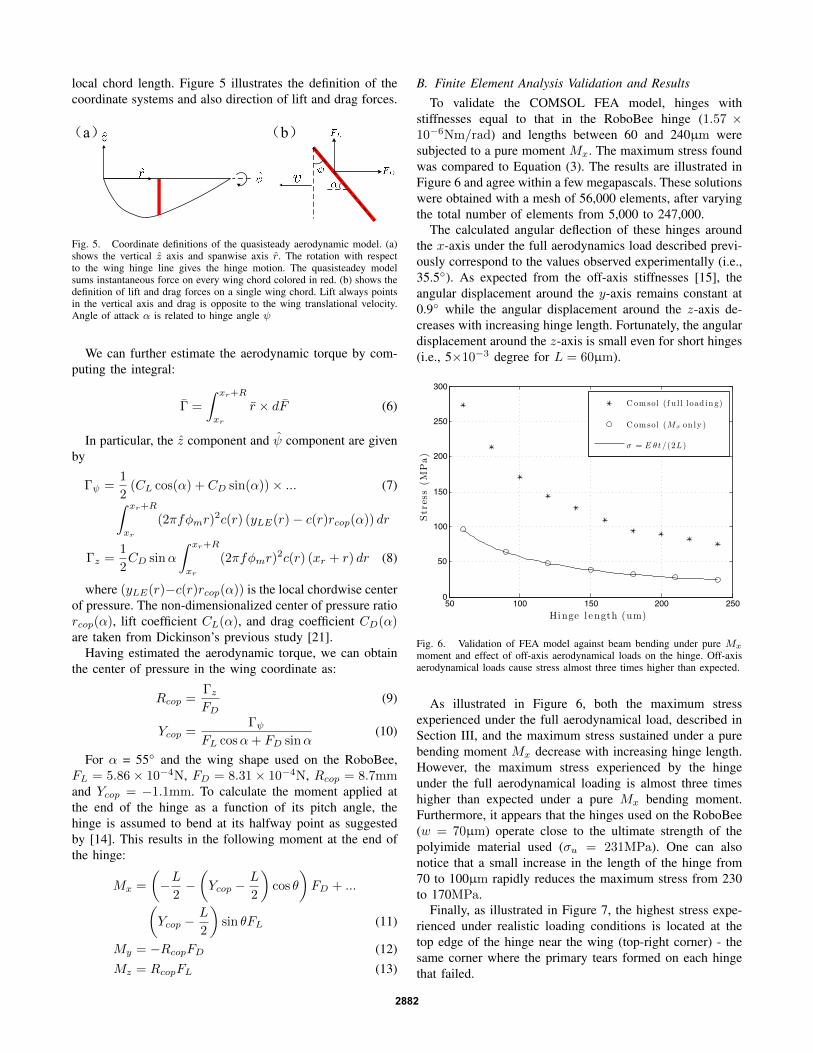
B. Finite Element Analysis Validation and ResultsTo validate the COMSOL FEA model, hinges with
stiffnesses equal to that in the RoboBee hinge (1.57 ×10⁻⁶Nm/rad) and lengths between 60 and 240µm weresubjected to a pure moment Mx. The maximum stress foundwas compared to Equation (3). The results are illustrated inFigure 6 and agree within a few megapascals. These solutionswere obtained with a mesh of 56,000 elements, after varyingthe total number of elements from 5,000 to 247,000.
The calculated angular deflection of these hinges aroundthe x-axis under the full aerodynamics load described previ-ously correspond to the values observed experimentally (i.e.,35.5◦). As expected from the off-axis stiffnesses [15], theangular displacement around the y-axis remains constant at0.9◦ while the angular displacement around the z-axis de-creases with increasing hinge length. Fortunately, the angulardisplacement around the z-axis is small even for short hinges(i.e., 5×10⁻³ degree for L = 60µm).
50 100 150 200 2500
50
100
150
200
250
300
Hinge l ength (um)
Str
ess
(MP
a)
Comsol (f u l l load ing)
C omsol (Mx on ly )
! = E " t /(2L)
Fig. 6. Validation of FEA model against beam bending under pure Mx
moment and effect of off-axis aerodynamical loads on the hinge. Off-axisaerodynamical loads cause stress almost three times higher than expected.
As illustrated in Figure 6, both the maximum stressexperienced under the full aerodynamical load, described inSection III, and the maximum stress sustained under a purebending moment Mx decrease with increasing hinge length.However, the maximum stress experienced by the hingeunder the full aerodynamical loading is almost three timeshigher than expected under a pure Mx bending moment.Furthermore, it appears that the hinges used on the RoboBee(w = 70µm) operate close to the ultimate strength of thepolyimide material used (σu = 231MPa). One can alsonotice that a small increase in the length of the hinge from70 to 100µm rapidly reduces the maximum stress from 230to 170MPa.
Finally, as illustrated in Figure 7, the highest stress expe-rienced under realistic loading conditions is located at thetop edge of the hinge near the wing (top-right corner) - thesame corner where the primary tears formed on each hingethat failed.
2882

60 um
7.5um
60um
1.1mm
Fig. 7. View along the rotational axis of a hinge (top figure) of thedisplacement and stress, illustrated by the color scale (units in Pascals) underthe full aerodynamical load. Bottom figure shows a view of the same hinge,this time with the thickness axis oriented out of the page. The maximumstress from this simulation, in the top-right corner of the bottom figure, islocated in the same corner as where the failures initiate experimentally.
IV. EXPERIMENTAL SETUP
A chamber specially designed for flapping-wing experi-ments was used to evaluate both stress concentration reduc-ing features and the effect of hinge sizing. The importantcomponents of this chamber are described in the followingsections.
A. Wing Driver and Force Sensor
Wings are flapped using the wing driver shown in Figure8. This mechanism converts the tip motion of a bimorphpiezoelectric actuator into the single degree of freedom wingstroke. Due to the inertial and aerodynamic forces generated,passive rotation occurs about the flexure hinge connecting thewing to the driver.
The wing driver was installed on the input plate of a twoaxis force sensor [22]. This sensor is made of a single sheetof 150µm Invar that is folded and welded into four paralleldual cantilevers, 4x4x7mm each. These beams are arrangedin a series-parallel configuration to convert loads transmittedthrough the input plate into orthogonal displacements alongthe y (vertical) and z axes (horizontal). Both y and z axeshave a sensitivity of approximately 85V/N and a resonantfrequency of 510Hz. Force signals were digitized at 5kHz.
More details about the wing driver and the force sensorcan be found in [23], [24].
B. Failure Detection
As described previously, failure starts at the top corner ofthe hinge closest to the wing. A crack propagates over theentire length of the hinge within 500-1000 flapping cycles,eventually causing complete detachment of the wing fromthe hinge. As the crack propagates, the wing motion changes
Alignment Stage
Capacitive Sensor
Wing Driver
Actuator Displacement SensorWing
Compound Beam Structure
Fig. 8. Wing driver assembly (from [23])
considerably leading to collision of the top and bottom partof the hinge. This results in a characteristic increases in thehorizontal force acting on the wing at the start of failure(Fig. 9). This spike in force was detected by comparing theinstantaneous value of the horizontal force to the maximumforce recorded during the first five seconds of the test. Whenthe instantaneous horizontal force became 1.5 times greaterthan the initial drag readings, the hinge was consideredbroken and the test was terminated.
209 210 211 212−0.05
−0.025
0
0.025
0.05
time (sec)
Dra
g (N
)
Normal �apping Ramp down
Hinge failure
Fig. 9. Typical horizontal force recorded during the last few secondsof flapping. This figure shows normal flapping and the spike in forcecaused during hinge failure. The control software detects the failure andslowly reduces the flapping amplitude to a complete stop before completedetachment of the wing from the hinge can happen.
C. Pitch and Stroke Angle Determination
The motion of the wing was recorded during six cyclesof flapping with a Phantom V7.3 camera equipped with anAF MICRO Nikkor 200mm f/4 lens positioned normal to thestroke plane. The resulting 10kHz video was post-processedto extract the pitch (i.e., hinge angle) and stroke angles ofthe wing. To do so, the wing area projected onto the imageframe and its major axes were extracted from each frame.This information was combined with the known position of
2883

the wing driver joints and the aspect ratio of the wing toextract the motion of the wing as described in [23].
V. RESULTS
A. Stress Concentration Reducing Features
The stress concentration reducing features were testedon the shorter-lived hinges and on a wing design slightlydifferent than what is used on the RoboBee. This winghas an aspect ratio of three and second moment of area of0.55, as presented in [23], and uses stiffer hinges (1.45mmx 125µm x 12.7µm) at a frequency of 160Hz. This wingwas used for initial testing of hinge alterations becausethe short-lifespan hinges would allow us to more quicklydetermine the relative effect of the different hinge designs.The results of the rounded corner and stress relief featuresin affecting hinge lifespan are shown in Figure 10a. For thistest, eight to nine hinges were flapped until failure for eachmodel. None of these features appeared to have a statisticallysignificant effect on lifespan. Figure 10b shows the resultsof another hinge test comparing different adhesive support:horizontal strips, vertical strips and stress relief features madeof the adhesive layer (three hinges per model). Hinges wereflapped until failure for each model. From our results, allforms of adhesive support had a negligible effect on lifespan.However, the acrylic adhesive used in our manufacturingprocess is very pliable and might not provide enough supportto counteract the hinge torsion. Using another, stiffer materialmight have led to a more significant result.
Original RoundedCorner
StressRelief
0
2
4
6
8 x 10⁴
Cyc
les
Original Horiz.Strip
Vert.Strip
Adhesive S.R.
0
2
4
6
8 x 10⁴
Cyc
les
Fig. 10. All hinges tested were short-lived hinges used for rapid testingand prototyping (1.45mm wide x 125µm long x 12.7µm thick). (left)Rounded corner and stress relief features showing negligible effects onlifespan compared to the standard hinges. The error bars show one standarddeviation, which in some cases is of similar magnitude as the hinge lifespan.A total of 8 hinges were tested for the original and stress relief features,and 9 for the rounded corner features. (right) Vertical adhesive support (each100 µm wide), horizontal adhesive support (each 15 µm tall), and stressrelief made from adhesive, also showing negligible lifespan enhancementcompared to the standard hinges. Two hinges were tested for the originalfeature, and 3 hinges for each of the horizontal strip, vertical strip, andadhesive stress relief features.
It is important to note that the hinges used to obtain eachgraph in Figure 10 come from different production runs. Dueto manufacturing variation these test can’t be compared toeach other directly. That is why each production run includesa control model (i.e., the original hinge).
These results show stress-reducing features have virtuallyno effect in extending hinge lifespan, suggesting the hingefailure is not due to a stress concentration caused by the
change in stiffness at the carbon-polyimide interface or thesharp corners of the hinge.
B. Hinge Sizing for Stress Reduction
As described earlier, longer hinges experience reducedstress for a given hinge bending motion, thickness, andYoung’s modulus. Furthermore, the hinge stiffness can bemaintained by increasing the hinge width by the same factor.To validate the effectiveness of this scaling technique toincrease the hinge lifespan, a hinge 30% longer and widerthan the short-lived protyping hinge was tested against hingeswith other stress-reducing features. The increased lifespan ofthis new hinge is compared to the effect of the stress concen-tration reduction features in Figure 11. This 30% increase inthe hinge length and width results in a 13× increase in itslifespan, without noticeably affecting its motion.
Regular RoundCorner
StressRelief
Lengthened0
0.5
1
1.5
2
2.5
3
3.5 x 10⁵
Cyc
les
Fig. 11. Hinge lifespan of standard flexure hinges, hinges with roundedcorners, hinges with stress relief, and regular hinges lengthened by 30percent. Lengthening the hinge significantly increases the lifespan of thehinge. Error bars indicate one standard deviation. Three hinges were testedfor all groups, and all hinges tested in this preliminary study were short-livedhinges for rapid testing and prototyping.
To further quantify how hinge length affects flexure hingelife, hinges with lengths varying from 55µm to 105µm weretested until failure in the wing testing chamber describedabove. Three hinges of each length were tested, and averagesof the number of cycles withstood for each hinge lengthwere found and plotted against length (Fig. 12). This datademonstrates that hinge lifespan is a function of length.The collected data fit with an exponential curve (R2 =0.87) where the lifespan increases with the length of thehinge. Although some materials like steel reach an infinitelifespan at a certain stress level, many polymers exhibit anexponential curve similar to the one observed in this work.
Hinges longer than 105µm were not tested as they lastedmultiple hours. This is more than sufficient for the currentRoboBee and also requires long tests on a shared instrument.It is believed that further increase of the hinge length willcontinue to increase their lifespan, up to a point where
2884

50 60 70 80 90 100 110104
105
106
107
Length (um)
Hin
ge L
ifesp
an (c
ycle
s)
y = 10exp(0.023912 * x + 3.821500)
Fig. 12. Hinge lifespan as a function of length for hinges of constantrevolute stiffness but varying length. This graph demonstrates the correlationbetween hinge length and lifespan, as predicted by equation 3. For eachlength, 3 hinges were tested using the longer-lived RoboBee hinge.
off-axis stiffness and flapping motion will be significantlyaffected.
Although all hinges were designed to have the same stiff-ness, wing motion was extracted to confirm that the resultingflapping motion was not affected by the dimensional changeof the hinges or manufacturing variations. Little differencewas found in hinge (34±1.4◦) and stroke (29.6±1.2◦) anglesof all the hinges used in the experiments. This confirms thatthe off-axis stiffnesses were not affected by the change inwidth and length, or remained high enough to sustain theloads created by flapping.
VI. CONCLUSION
This paper explored the failure mode of the complianthinges used as the passive pitch joint of the RoboBee wing.These flexure hinges, consisting of a laminate of carbon fibercomposites and thin polyimide film typically last approxi-mately 10 minutes. Various methods were proposed to reducethe stress sustained by the hinge during normal flappingwhile keeping the stiffness - a characteristic critical toproper passive wing rotation - constant. Using experimentaltechniques, simple beam bending modeling and FEA, it wasdetermined that (1) high stress at the corners of the hingewere not due to the sharp corners or stiffness transition,(2) off-axis loads contributed significantly to the total stressexperienced by the hinge, and (3) increasing length andwidth substantially reduced the stress in the hinge withoutnoticeable impact on the wing motion.
The experiments further revealed that slight modificationto the dimensions can easily increase the lifespan of thesehinges from a few minutes (70,000 cycles) to several hours(2,000,000+ cycles). Although material selection or thicknesscould still lead to improvements, longer polyimide hingesare currently being implemented into the newly fabricatedRoboBees. More generally, the simple design rule detailed
in this paper should prove useful to anyone designing multi-layer flexure-based mechanisms.
REFERENCES
[1] R. Wood, S. Avadhanula, R. Sahai, E. Steltz, and R. Fearing, “Micro-robot design using fiber reinforced composites,” Journal of MechanicalDesign, vol. 130, p. 052304, 2008.
[2] J. Whitney, P. Sreetharan, K. Ma, and R. Wood, “Pop-up book mems,”Journal of Micromechanics and Microengineering, vol. 21, no. 11, p.115021, 2011.
[3] A. Baisch, O. Ozcan, B. Goldberg, D. Ithier, and R. Wood, “Highspeed locomotion for a quadrupedal microrobot,” International Jour-nal of Robotics Research, In Press.
[4] P. Birkmeyer, K. Peterson, and R. S. Fearing, “Dash: A dynamic 16ghexapedal robot,” in Intelligent Robots and Systems, 2009. IROS 2009.IEEE/RSJ International Conference on. IEEE, 2009, pp. 2683–2689.
[5] A. M. Hoover, S. Burden, X.-Y. Fu, S. S. Sastry, and R. S. Fearing,“Bio-inspired design and dynamic maneuverability of a minimally ac-tuated six-legged robot,” in Biomedical Robotics and Biomechatronics(BioRob), 2010 3rd IEEE RAS and EMBS International Conferenceon. IEEE, 2010, pp. 869–876.
[6] K. Y. Ma, P. Chirarattananon, S. B. Fuller, and R. J. Wood, “Controlledflight of a biologically inspired, insect-scale robot,” Science, vol. 340,no. 6132, pp. 603–607, 2013.
[7] J. O. Jacobsen, B. G. Winder, L. L. Howell, and S. P. Magleby,“Lamina emergent mechanisms and their basic elements.” ASME,2010.
[8] S. M. Felton, M. T. Tolley, B. Shin, C. D. Onal, E. D. Demaine,D. Rus, and R. Wood, “Self-folding with shape memory composites,”Soft Matter, 2013.
[9] E. Hawkes, B. An, N. Benbernou, H. Tanaka, S. Kim, E. Demaine,D. Rus, and R. Wood, “Programmable matter by folding,” Proceedingsof the National Academy of Sciences, vol. 107, no. 28, pp. 12 441–12 445, 2010.
[10] J. Gafford, S. Kesner, R. Wood, and C. Walsh, “Microsurgical devicesby pop-up book mems,” ASME/IDETC: Robotics and Mechanisms inMedicine, 2013.
[11] S. P. Sane, “The aerodynamics of insect flight,” The journal ofexperimental biology, vol. 206, no. 23, pp. 4191–4208, 2003.
[12] A. J. Bergou, S. Xu, and Z. Wang, “Passive wing pitch reversal ininsect flight,” Journal of Fluid Mechanics, vol. 591, no. 1, pp. 321–337, 2007.
[13] W. Glaeser, Materials for tribology. Access Online via Elsevier, 1992,vol. 20.
[14] L. L. Howell, Compliant mechanisms. Wiley-Interscience, 2001.[15] M. Goldfarb and J. E. Speich, “A well-behaved revolute flexure joint
for compliant mechanism design,” Journal of Mechanical Design, vol.121, p. 424, 1999.
[16] L. U. Odhner and A. M. Dollar, “Toward simpler models of bendingsheet joints,” in Intelligent Robots and Systems (IROS), 2011 IEEE/RSJInternational Conference on. IEEE, 2011, pp. 1420–1426.
[17] S. T. Smith, V. G. Badami, J. S. Dale, and Y. Xu, “Elliptical flexurehinges,” Review of Scientific Instruments, vol. 68, no. 3, pp. 1474–1483, 1997.
[18] N. Lobontiu, Compliant mechanisms: design of flexure hinges. CRCpress, 2003.
[19] R. J. Wood, “Design, fabrication, and analysis of a 3dof, 3cm flapping-wing mav,” in Intelligent Robots and Systems, 2007. IROS 2007.IEEE/RSJ International Conference on. IEEE, 2007, pp. 1576–1581.
[20] Dupont, “Summary of properties for kapton polyimide films,” online,2014.
[21] M. H. Dickinson, F.-O. Lehmann, and S. P. Sane, “Wing rotation andthe aerodynamic basis of insect flight,” Science, vol. 284, no. 5422,pp. 1954–1960, 1999.
[22] R. J. Wood, K. Cho, and K. Hoffman, “A novel multi-axis forcesensor for microrobotics applications,” Smart materials and structures,vol. 18, no. 12, p. 125002, 2009.
[23] A. Lussier Desbiens, Y. Chen, and R. J. Wood, “A wing characteriza-tion method for flapping-wing robotic insects,” in Intelligent Robotsand Systems (IROS), 2013 IEEE/RSJ International Conference on.IEEE, 2013, pp. 1367–1373.
[24] J. P. Whitney, “Design and performance of insect-scale flapping-wingvehicles,” Ph.D. dissertation, Harvard University, 2012.
2885