Embed Size (px)
Citation preview

MDKCMDKDDiesel SeriesPrinted in U.S.A. 5-90
981-0600
Page 1 of 1
Supplement: 981-1054Date: 12-05Insert with: Installation Manual 981-0604 (09-96)
Installation Manual 981-0621 (05-00)Installation Manual 981-0631B (05-04)Installation Manual 981-0636 (06-03)Installation Manual 983-0600 (05-00)Installation Manual 983-0601 (11-01)
This supplement transmits changes that reflect Federal and California standards for gasoline evaporativeemissions that become effective January 1, 2006. Please insert this sheet under the front cover of the manual.
The following items apply in addition to the requirements covered in the Fuel System or Fuel Connectionssection of the generator set Installation Manual in which this Supplement is inserted:
1. Flexible Gasoline Hoses: The fuel hoses used inside the generator set meet the Federal and Californiastandards for gasoline evaporative emissions. The requirements also apply to the gasoline supply hosebetween the tank and generator set. Special hose is required to meet these requirements for gasolinegenerator sets sold in or used for commerce in the State of California. See your Onan Distributor.
2. Connecting Gasoline Hoses: Lubricants used when connecting fuel hoses can leave residues that canclog fuel jets. Only use “soap-free” lubricants such as WD40.
CAUTION When connecting fuel hoses, only use soap-free lubricants such as WD40, whichruns through with the fuel without leaving residues that can clog fuel jets.
Copy and post these suggestions in potential hazard areas of the vessel.
Safety Precautions
Before operating the generator set, read the Operator’sManual and become familiar with it and your unit. Safe and ef-ficient operation can be achieved only if the unit is properlyoperated and maintained. Many accidents are caused by fail-ure to follow fundamental rules and precautions.
Throughout this manual you will notice symbols which alert youto potentially dangerous conditions to the operator, service per-sonnel, or the equipment itself.
This symbol warns of immediate haz-ards which will result in severe personal injury ordeath.
This symbol refers to a hazard or unsafepractice which can result in severe personal injury ordeath.
This symbol refers to a hazard or unsafepractice which can result in personal injury or prod-uct or property damage.
FUEL, ENGINE OIL, AND FUMES ARE FLAMMABLE ANDTOXIC. Fire, explosion, and personal injury can result from im-proper practices.
• Benzene and lead, found in some gasoline, have beenidentified by some state and federal agencies as causingcancer or reproductive toxicity. When checking, drainingor adding gasoline, take care not to ingest, breathe thefumes, or contact gasoline.
• Used engine oils have been identified by some state orfederal agencies as causing cancer or reproductive toxic-ity. When checking or changing engine oil, take care not toingest, breathe the fumes, or contact used oil.
• Do not fill fuel tanks with the engine running. Do not smokearound the generator set area. Wipe up any oil or gasspills. Do not leave oily rags in engine compartment or onthe generator set. Keep this and surrounding area clean.
• Inspect fuel system before each operation and periodicallywhile running.
• Equip the engine fuel supply with a positive fuel shutoff.
• Always disconnect the battery ground (−) lead first and re-connect it last. Make sure you connect the battery correct-ly. A direct short across the battery terminals can cause anexplosion. Do not smoke while servicing batteries. Hydro-gen gas given off during charging is very explosive.
• Keep a fire extinguisher available in or near the enginecompartment and in other areas throughout the vessel.Use the correct extinguisher for the area. For most typesof fires, an extinguisher rated ABC by the NFPA is avail-able and suitable for use on all types of fires except alco-hol.
EXHAUST GASES ARE DEADLY• Provide adequate ventilation. Equip the bilge with a power
exhauster.
• Be sure propulsion and generator set engine exhaust sys-tems are free of leaks. Perform thorough, periodic inspec-tions of the exhaust system and repair leaks immediately.Exhaust gases are deadly.
• Never sleep in the vessel with the generator set runningunless the vessel is equipped with an operating carbonmonoxide detector.
HOT COOLANT CAN CAUSE SEVERE PERSONALINJURY• Hot coolant is under pressure. Do not loosen the coolant
pressure cap while the engine is hot. Let the engine coolbefore opening the pressure cap.
MOVING PARTS CAN CAUSE SEVERE PERSONALINJURY OR DEATH• Do not remove any belt guards or covers with the genera-
tor set running.
• Keep hands and loose clothing away from moving parts.Do not wear jewelry while servicing any part of the genera-tor set.
• Never step on the generator set (as when entering or leav-ing the engine compartment). It can stress and break unitcomponents, possible resulting in dangerous operatingconditions. . . from leaking fuel, leaking exhaust fumes,etc.
• Before performing any maintenance on the generator set,disconnect its batteries to prevent accidental starting. donot disconnect or connect battery cables if fuel vapors arepresent. Ventilate the generator set compartment or bilgethoroughly with the power exhauster.
ELECTRICAL SHOCK WILL CAUSE SEVEREPERSONAL INJURY OR DEATH• Do not make adjustments in the control panel or on engine
with unit running. High voltages are present. Work thatmust be done while unit is running should be done only byqualified service personnel standing on dry surfaces to re-duce shock hazard.
• DO NOT CONNECT THE GENERATOR SET TO THEPUBLIC UTILITY OR TO ANY OTHER ELECTRICALPOWER SYSTEM. Electrocution or damage to propertycan occur at a site remote from the boat where line orequipment repairs are being made if the set is connectedto the power system. An approved transfer switch must beused if more than one power source is to be made avail-able to service the boat.
• Do not work on this equipment when mentally or physicallyfatigued, or after consuming any alcohol or drug thatmakes the operation of equipment unsafe.

i
Table of Contents
SECTION TITLE PAGE. . . . . . . . . . . . . . . . . . . . . . . . . . . . . . . . . . . . . . . . . . . . . . . . . . . . . . . . . . . . . .
SAFETY PRECAUTIONS Inside Front Cover. . . . . . . . . . . . . . . . . . . . . . . . . . . . . . . . . . . .
1 INTRODUCTION 1-1. . . . . . . . . . . . . . . . . . . . . . . . . . . . . . . . . . . . . . . . . . . . . . . . . . . . . . . . General 1-1. . . . . . . . . . . . . . . . . . . . . . . . . . . . . . . . . . . . . . . . . . . . . . . . . . . . . . . . . . . . . . Installation Codes and Safety Recommendations 1-1. . . . . . . . . . . . . . . . . . . . . . . . . .
2 SPECIFICATIONS 2-1. . . . . . . . . . . . . . . . . . . . . . . . . . . . . . . . . . . . . . . . . . . . . . . . . . . . . . . Generator Details 2-1. . . . . . . . . . . . . . . . . . . . . . . . . . . . . . . . . . . . . . . . . . . . . . . . . . . . . . Engine Details 2-1. . . . . . . . . . . . . . . . . . . . . . . . . . . . . . . . . . . . . . . . . . . . . . . . . . . . . . . . .
3 LOCATION and MOUNTING 3-1. . . . . . . . . . . . . . . . . . . . . . . . . . . . . . . . . . . . . . . . . . . . . . Location 3-1. . . . . . . . . . . . . . . . . . . . . . . . . . . . . . . . . . . . . . . . . . . . . . . . . . . . . . . . . . . . . . Mounting 3-1. . . . . . . . . . . . . . . . . . . . . . . . . . . . . . . . . . . . . . . . . . . . . . . . . . . . . . . . . . . . . Sound Attenuation Housing 3-1. . . . . . . . . . . . . . . . . . . . . . . . . . . . . . . . . . . . . . . . . . . . .
4 VENTILATION 4-1. . . . . . . . . . . . . . . . . . . . . . . . . . . . . . . . . . . . . . . . . . . . . . . . . . . . . . . . . . General 4-1. . . . . . . . . . . . . . . . . . . . . . . . . . . . . . . . . . . . . . . . . . . . . . . . . . . . . . . . . . . . . . Requirements 4-1. . . . . . . . . . . . . . . . . . . . . . . . . . . . . . . . . . . . . . . . . . . . . . . . . . . . . . . . . Coast Guard and NFPA Requirements 4-1. . . . . . . . . . . . . . . . . . . . . . . . . . . . . . . . . . .
5 COOLING SYSTEM 5-1. . . . . . . . . . . . . . . . . . . . . . . . . . . . . . . . . . . . . . . . . . . . . . . . . . . . . . General 5-1. . . . . . . . . . . . . . . . . . . . . . . . . . . . . . . . . . . . . . . . . . . . . . . . . . . . . . . . . . . . . . Heat Exchanger Cooling 5-2. . . . . . . . . . . . . . . . . . . . . . . . . . . . . . . . . . . . . . . . . . . . . . . . Keel Cooling 5-3. . . . . . . . . . . . . . . . . . . . . . . . . . . . . . . . . . . . . . . . . . . . . . . . . . . . . . . . . . Combined Cooling Systems 5-3. . . . . . . . . . . . . . . . . . . . . . . . . . . . . . . . . . . . . . . . . . . . . Cooling System Check 5-3. . . . . . . . . . . . . . . . . . . . . . . . . . . . . . . . . . . . . . . . . . . . . . . . .
6 EXHAUST SYSTEM 6-1. . . . . . . . . . . . . . . . . . . . . . . . . . . . . . . . . . . . . . . . . . . . . . . . . . . . . General 6-1. . . . . . . . . . . . . . . . . . . . . . . . . . . . . . . . . . . . . . . . . . . . . . . . . . . . . . . . . . . . . . Below Load-Waterline Installation 6-2. . . . . . . . . . . . . . . . . . . . . . . . . . . . . . . . . . . . . . . . Above Load-Waterline Installation 6-4. . . . . . . . . . . . . . . . . . . . . . . . . . . . . . . . . . . . . . . .
7 FUEL SYSTEM 7-1. . . . . . . . . . . . . . . . . . . . . . . . . . . . . . . . . . . . . . . . . . . . . . . . . . . . . . . . . . General 7-1. . . . . . . . . . . . . . . . . . . . . . . . . . . . . . . . . . . . . . . . . . . . . . . . . . . . . . . . . . . . . . Fuel Lines 7-1. . . . . . . . . . . . . . . . . . . . . . . . . . . . . . . . . . . . . . . . . . . . . . . . . . . . . . . . . . . . Siphon Protection 7-2. . . . . . . . . . . . . . . . . . . . . . . . . . . . . . . . . . . . . . . . . . . . . . . . . . . . . . Fuel Tanks 7-2. . . . . . . . . . . . . . . . . . . . . . . . . . . . . . . . . . . . . . . . . . . . . . . . . . . . . . . . . . . . Fuel System Test 7-3. . . . . . . . . . . . . . . . . . . . . . . . . . . . . . . . . . . . . . . . . . . . . . . . . . . . . .
8 ELECTRICAL SYSTEM 8-1. . . . . . . . . . . . . . . . . . . . . . . . . . . . . . . . . . . . . . . . . . . . . . . . . . General 8-1. . . . . . . . . . . . . . . . . . . . . . . . . . . . . . . . . . . . . . . . . . . . . . . . . . . . . . . . . . . . . . Load Connections 8-1. . . . . . . . . . . . . . . . . . . . . . . . . . . . . . . . . . . . . . . . . . . . . . . . . . . . . Remote Controls 8-8. . . . . . . . . . . . . . . . . . . . . . . . . . . . . . . . . . . . . . . . . . . . . . . . . . . . . . Battery 8-8. . . . . . . . . . . . . . . . . . . . . . . . . . . . . . . . . . . . . . . . . . . . . . . . . . . . . . . . . . . . . . . Bonding 8-10. . . . . . . . . . . . . . . . . . . . . . . . . . . . . . . . . . . . . . . . . . . . . . . . . . . . . . . . . . . . .
9 FINAL INSTALLATION CHECKS 9-1. . . . . . . . . . . . . . . . . . . . . . . . . . . . . . . . . . . . . . . . . . Installation Checks 9-1. . . . . . . . . . . . . . . . . . . . . . . . . . . . . . . . . . . . . . . . . . . . . . . . . . . . . Initial Starting and Checks 9-1. . . . . . . . . . . . . . . . . . . . . . . . . . . . . . . . . . . . . . . . . . . . . . Voltage Adjustment 9-1. . . . . . . . . . . . . . . . . . . . . . . . . . . . . . . . . . . . . . . . . . . . . . . . . . . .

1-1
Section 1. Introduction
GENERAL
Each marine genset must be installed properly if it is tooperate reliable, quietly, and most importantly—safely.Therefore, read this entire manual before starting theinstallation. The manual should be used only as a guide,as each installation must be considered on an individualbasis. For operation and maintenance procedures, referto the Operator’s Manual 981-0120 that accompanieseach genset.
Proper installation is very important. Requirements toconsider include:
• Adequate cooling air
• Adequate combustion air
• Discharge of exhaust gases
• Discharge of circulated air
• Electrical connections and bonding
• Fuel connections
• Sea water connection
• Accessibility for operation and servicing
• Level mounting surface
• Adequate support under mounting points
• Noise levels
INSTALLATION CODES AND SAFETYRECOMMENDATIONS
The installation must follow recommendations of theAmerican Boat and Yacht Council (ABYC) and the Na-tional Fire Protection Association (NFPA).
The installer should be familiar with the appropriate guid-ance found in the following publications:
ABYC “Safety Standards for Small Craft” from:
ABYC15 East 26th St.New York, NY 10010
NFPA302 “Fire Protection Standard for Motor Craft”from:
NFPA470 Atlantic Ave.Boston, MA 02210
USCG 33CFR183 from:
U.S. Government Printing OfficeWashington, D.C. 20404
INCORRECT SERVICE OR REPLACEMENT OF PARTS CAN RESULT IN SEVEREPERSONAL INJURY, DEATH, AND/OR EQUIPMENT DAMAGE. SERVICE PER-SONNEL MUST BE QUALIFIED TO PERFORM ELECTRICAL AND/OR MECHANI-CAL SERVICE.

2-1
Section 2. Specifications
GENERATOR DETAILS Type Onan , Revolving Field, 4-Pole, Brushless. . . . . . . . . . . . . . . . . . . . . . . . . . . . . . . . . . . . . . . . . . . . . . . . Standby Ratings:
60 Hertz General Marine Rating, 8.0 MDKD-A, B, J, 1-phase 8.0 kW, 8.0 kVA at 1.0 PF. . . . . . . . . . 8.0 MDKD-L, 3-phase 8.0 kW, 10.0 kVA at 0.8 PF. . . . . . . . . . . . . . 4.0 MDKC-A, B, J, 1-phase 4.0 kW, 4.0 kVA at 1.0 PF. . . . . . . . . . 4.0 MDKC-L, 3-phase 4.0 kW, 5.0 kVA at 0.8 PF. . . . . . . . . . . . . . .
50 Hertz General Marine Rating, 6.5 MDKD-P, 1-phase 6.5 kW, 6.5 kVA at 1.0 PF. . . . . . . . . . . . . . . 6.5 MDKD-Z, 3-phase 6.5 kW, 8.1 kVA at 0.8 PF. . . . . . . . . . . . . . . 3.5 MDKC-P, 1-phase 3.5 kW, 3.5 kVA at 1.0 PF. . . . . . . . . . . . . . . 3.5 MDKC-Z, 3-phase 3.5 kW, 4.4 kVA at 0.8 PF. . . . . . . . . . . . . . .
Frequency Regulation, No-load To Full-load 5%. . . . . . . . . . . . . . . . . . . . . . . . . . . . . . . . . . . . . . . . . . . . . . . . . AC Voltage Regulation:
Electronic Regulation ±2%. . . . . . . . . . . . . . . . . . . . . . . . . . . . . . . . . . . . . . . . . . . . . . . . . . . . . . . . . . . . . . . . . . Magnetic Regulation ±5%. . . . . . . . . . . . . . . . . . . . . . . . . . . . . . . . . . . . . . . . . . . . . . . . . . . . . . . . . . . . . . . . . .
ENGINE DETAILS Battery Charge Alternator Maximum Output (Regulated) 10 Amperes. . . . . . . . . . . . . . . . . . . . . . . . . . . . . Battery Voltage 12 Volts. . . . . . . . . . . . . . . . . . . . . . . . . . . . . . . . . . . . . . . . . . . . . . . . . . . . . . . . . . . . . . . . . . . . . . Battery Recommendation, Minimum Cranking Performance @ 0° F (-18° C) 360 Ampere. . . . . . . . . . . . Engine Type Diesel, 3 Cylinder, Vertical In-Line. . . . . . . . . . . . . . . . . . . . . . . . . . . . . . . . . . . . . . . . . . . . . . . . . Engine Speed, 60/50 Hertz 1800/1500 rpm. . . . . . . . . . . . . . . . . . . . . . . . . . . . . . . . . . . . . . . . . . . . . . . . . . . . . Exhaust Outlet Size, ID 2 Inches. . . . . . . . . . . . . . . . . . . . . . . . . . . . . . . . . . . . . . . . . . . . . . . . . . . . . . . . . . . . . . Fuel No.2 Diesel. . . . . . . . . . . . . . . . . . . . . . . . . . . . . . . . . . . . . . . . . . . . . . . . . . . . . . . . . . . . . . . . . . . . . . . . . . . . Fuel Inlet Size 1/8-27 NPT, Female. . . . . . . . . . . . . . . . . . . . . . . . . . . . . . . . . . . . . . . . . . . . . . . . . . . . . . . . . . . . Fuel Pump Lift (Self-priming) 4 ft (1.2 m). . . . . . . . . . . . . . . . . . . . . . . . . . . . . . . . . . . . . . . . . . . . . . . . . . . . . . . Fuel Consumption, Average @ Full Load:
3.5 MDKC 0.42 gph (1.57 L/h). . . . . . . . . . . . . . . . . . . . . . . . . . . . . . . . . . . . . . . . . . . . . . . . . . . . . . . . . . . . . . 4.0 MDKC 0.50 gph (1.89 L/h). . . . . . . . . . . . . . . . . . . . . . . . . . . . . . . . . . . . . . . . . . . . . . . . . . . . . . . . . . . . . . 6.5 MDKD 0.75 gph (3.12 L/h). . . . . . . . . . . . . . . . . . . . . . . . . . . . . . . . . . . . . . . . . . . . . . . . . . . . . . . . . . . . . . 8.0 MDKD 0.90 gph (3.75 L/h). . . . . . . . . . . . . . . . . . . . . . . . . . . . . . . . . . . . . . . . . . . . . . . . . . . . . . . . . . . . . .
Cooling System:Sea Water Flow Rate, New Pump
60 Hertz 2.5 gpm (9.5 lpm). . . . . . . . . . . . . . . . . . . . . . . . . . . . . . . . . . . . . . . . . . . . . . . . . . . . . . . . . . . . . . . 50 Hertz 3.0 gpm (11 lpm). . . . . . . . . . . . . . . . . . . . . . . . . . . . . . . . . . . . . . . . . . . . . . . . . . . . . . . . . . . . . . . .
Sea Water Pump Dry Lift, Maximum 3.0 feet (.91 liter). . . . . . . . . . . . . . . . . . . . . . . . . . . . . . . . . . . . . . . . . Sea Water Pump Hose Inlet Size, ID0.75 in (19.0 mm)Captive Coolant Flow Rate, Thermostat Open:
60 Hertz 2.7 gpm (10.2 L/min). . . . . . . . . . . . . . . . . . . . . . . . . . . . . . . . . . . . . . . . . . . . . . . . . . . . . . . . . . . . 50 Hertz 2.25 gpm (8.5 L/min). . . . . . . . . . . . . . . . . . . . . . . . . . . . . . . . . . . . . . . . . . . . . . . . . . . . . . . . . . . .
Heat Rejection @ Full Load:3.5 MDKC 21,000 BTU/min. . . . . . . . . . . . . . . . . . . . . . . . . . . . . . . . . . . . . . . . . . . . . . . . . . . . . . . . . . . . . . . 4.0 MDKC 32,000 BTU/min. . . . . . . . . . . . . . . . . . . . . . . . . . . . . . . . . . . . . . . . . . . . . . . . . . . . . . . . . . . . . . . 6.5 MDKD 42,000 BTU/min. . . . . . . . . . . . . . . . . . . . . . . . . . . . . . . . . . . . . . . . . . . . . . . . . . . . . . . . . . . . . . . 8.0 MDKD 48,000 BTU/min. . . . . . . . . . . . . . . . . . . . . . . . . . . . . . . . . . . . . . . . . . . . . . . . . . . . . . . . . . . . . . .
Cooling System Capacity, Including Heat Exchanger 3 quarts (2.8 L). . . . . . . . . . . . . . . . . . . . . . . . . . . . Total Air Per Minute Required (Cooling And Combustion):
3.5 MDKC 150 ft3/min (4.2 m3/min). . . . . . . . . . . . . . . . . . . . . . . . . . . . . . . . . . . . . . . . . . . . . . . . . . . . . . . . . 4.0 MDKC 170 ft3/min (4.8 m3/min). . . . . . . . . . . . . . . . . . . . . . . . . . . . . . . . . . . . . . . . . . . . . . . . . . . . . . . . . 6.5 MDKD 160 ft3/min (4.5 m3/min). . . . . . . . . . . . . . . . . . . . . . . . . . . . . . . . . . . . . . . . . . . . . . . . . . . . . . . . . 8.0 MDKD 180 ft3/min (5.1 m3/min). . . . . . . . . . . . . . . . . . . . . . . . . . . . . . . . . . . . . . . . . . . . . . . . . . . . . . . . .
Oil Capacity With Filter 4 qt. (3.8 L). . . . . . . . . . . . . . . . . . . . . . . . . . . . . . . . . . . . . . . . . . . . . . . . . . . . . . . . . . .
3-1
Section 3. Location and Mounting
LOCATION
The genset location must be a well ventilated area, insu-lated, close to the fuel supply and the center of electricalload distribution. Usually those conditions are in thesame room or compartment as the propulsion engine.However, a genset cannot be installed in the propulsionengine compartment unless specific conditions are met.
USCG regulation 33CFR183 pertains to gasoline fuelsystems, and requires a genset operating in a gasolinefuel environment to be ”ignition protected.” This means agenset capable of operating in an explosive environmentwithout igniting that environment.
The MDKC/MDKD gensets are not “ignition protected”and cannot be operated in a gasoline-fueled environ-ment. They can, however, be operated in a diesel-fuelenvironment.
Gasoline fire or explosion can result insevere personal injury or death. Do not install a die-sel generator set in the same room or compartmentof a gasoline propulsion engine or generator set.The diesel unit may not be ignition protected and canignite gasoline fumes.
Select a location that will allow adequate space on allsides for ventilation and servicing the set, preferably onand parallel with the keel or vessel center line. Keep thegenset away from living quarters, and away from bilgesplash and vapors.
MOUNTING
The floor must be flat and give support directly under thegenset mounting points (Figure 3-3). A one inch (25 mm)clearance around the unit is required to permit rocking onits mounts without restraint. Additional space must be al-lowed for proper air-ventilation for cooling and combus-tion, as well as service access. Also, allow access for pe-riodic maintenance such as oil fill, coolant fill, spark plugreplacement, etc. The entire exhaust system must be ac-cessible so a periodic visual and audible check for leak-age can be made by the operator.
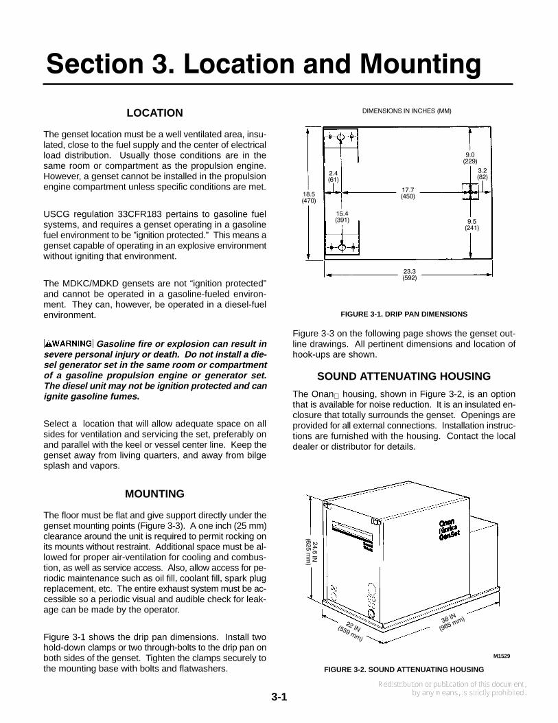
Figure 3-1 shows the drip pan dimensions. Install twohold-down clamps or two through-bolts to the drip pan onboth sides of the genset. Tighten the clamps securely tothe mounting base with bolts and flatwashers.
DIMENSIONS IN INCHES (MM)
2.4(61)
3.2(82)
18.5(470)
9.0(229)
15.4(391)
17.7(450)
9.5(241)
23.3(592)
FIGURE 3-1. DRIP PAN DIMENSIONS
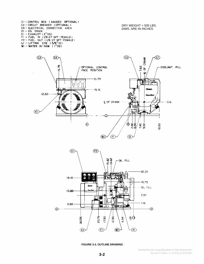
Figure 3-3 on the following page shows the genset out-line drawings. All pertinent dimensions and location ofhook-ups are shown.
SOUND ATTENUATING HOUSING
The Onan housing, shown in Figure 3-2, is an optionthat is available for noise reduction. It is an insulated en-closure that totally surrounds the genset. Openings areprovided for all external connections. Installation instruc-tions are furnished with the housing. Contact the localdealer or distributor for details.
M1529
FIGURE 3-2. SOUND ATTENUATING HOUSING
3-2
DRY WEIGHT = 505 LBS.DIMS. ARE IN INCHES
FIGURE 3-3. OUTLINE DRAWING
4-1
Section 4. Ventilation
GENERAL
The installation of boat ventilation systems must meet allCoast Guard and NFPA requirements. Establishing thecorrect air flow quantity is particularly important withsmall compartments under 1000 cubic feet (28 m3), orinstallations in close quarters. Ventilation systems meet-ing Coast Guard requirements for passenger vessels(Table 4-1) will normally suffice for operation under allconditions.
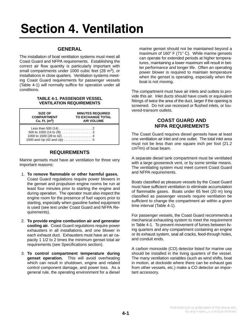
TABLE 4-1. PASSENGER VESSELVENTILATION REQUIREMENTS
SIZE OF MINUTES REQUIREDCOMPARTMENT TO EXCHANGE TOTAL
Cu. Ft. (m 3) AIR VOLUME
Less than 500 (14) 2. . . . . . . . . . . . . . . . . . . . 500 to 1000 (14 to 28) 3. . . . . . . . . . . . . . . . . . 1000 to 1500 (28 to 42) 4. . . . . . . . . . . . . . . . . .
1500 and Up (42 and Up) 5. . . . . . . . . . . . . . . . .
REQUIREMENTS
Marine gensets must have air ventilation for three veryimportant reasons:
1. To remove flammable or other harmful gases. Coast Guard regulations require power blowers inthe genset and propulsion engine rooms be run atleast four minutes prior to starting the engine andduring operation. The operator must also inspect theengine room for the presence of fuel vapors prior tostarting, especially when gasoline fueled equipmentis used (see text under Coast Guard and NFPA Re-quirements).
2. To provide engine combustion air and generatorcooling air. Coast Guard regulations require powerexhausters in all installations, and one blower ineach exhaust duct. Exhausters must have an air ca-pacity 1 1/2 to 2 times the minimum genset total airrequirements (see Specifications section).
3. To control compartment temperature duringgenset operation. This will avoid overheatingwhich can result in shutdown, engine and relatedcontrol component damage, and power loss. As ageneral rule, the operating environment for a diesel
marine genset should not be maintained beyond amaximum of 160° F (71° C). While marine gensetscan operate for extended periods at higher tempera-tures, maintaining a lower maximum will result in bet-ter performance and longer life. Often an operatingpower blower is required to maintain temperaturewhen the genset is operating, especially when theboat is not moving.
The compartment must have air inlets and outlets to pro-vide this air. Inlet ducts should have cowls or equivalentfittings of twice the area of the duct, larger if the opening isscreened. Do not use recessed or flushed inlets, or lou-vered-transom outlets.
COAST GUARD ANDNFPA REQUIREMENTS
The Coast Guard requires diesel gensets have at leastone ventilation air inlet and one outlet. The total inlet areamust not be less than one square inch per foot (21.2cm2/m) of boat beam.
A separate diesel tank compartment must be ventilatedwith a large gooseneck vent, or by some similar means.The ventilating system must meet current Coast Guardand NFPA requirements.
Boats classified as pleasure vessels by the Coast Guardmust have sufficient ventilation to eliminate accumulationof flammable gases. Boats under 65 feet (20 m) longclassified as passenger vessels require ventilation besufficient to change the compartment air within a giventime interval (Table 4-1).
For passenger vessels, the Coast Guard recommends amechanical exhausting system to meet the requirementin Table 4-1. To prevent movement of fumes between liv-ing quarters and any compartment containing an engineor its exhaust system, seal all cracks, feed-through holes,and conduit ends.
A carbon monoxide (CO) detector listed for marine useshould be installed in the living quarters of the vessel.The many ventilation variables (such as wind shifts, boatin motion, at dockside where there can be exhaust gasfrom other vessels, etc.) make a CO detector an impor-tant accessory.

5-1
Section 5. Cooling System
GENERAL
Throughout this manual, flotation water drawn into theboat for engine cooling is called sea water. Thus, confu-sion is avoided with other generic terms describing waterorigin and use.
The two types of marine cooling systems described inthis manual are heat exchanger and keel cooling. An ex-planation of each system, and the advantages and disad-vantages of each are covered in separate sections. Theheat exchanger system is used most often, and is stan-dard on the MDKC/MDKD gensets.
System Plumbing
To adequately cool the genset under all conditions, theplumbing system must be properly planned and installed.Excess lengths of plumbing increases flow resistanceand results in reduced cooling. An air leak in the sea wa-ter intake will reduce cooling, cause corrosion, and caneven destroy the neoprene impeller in the sea waterpump. The neoprene impeller must never be run dry, andthe pump should be primed before initial start.
The water line should have a minimum inside diameter of0.75 inch (19 mm). For runs over 20 feet (5.2 m), in-crease the line one pipe size for each additional 10 feet(2.6 m) of length. Water lines can be either copper tubingor flexible hose. Be sure a length of flexible hose is usedat the genset connection to allow set movement, and fornoise abatement.
Because sea water cannot be relied upon to always beclean, Onan recommends a water strainer or filter to pro-tect the engine cooling system. See Figure 5-1.
Onan has a hull strainer (furnished with some mufflerkits) that can be used with a flush through-hull fitting. Thestrainer (Figure 5-1), installed with the slots parallel to thekeel, helps prevent pressure or vacuum when the boat isunderway. Always use a flush-type inlet with a hydrody-namic marine muffler.
CS1312-1
CROSS−SECTIONVIEW
HULLSTRAINER
SEACOCK
RECOMMENDEDWATER STRAINER
OR FILTER
FLUSH THRU−HULL FITTING
TOGENSET
FIGURE 5-1. SEA WATER INLET
Restriction in the sea water inlet line cancause engine overheating and shutdown. The flush-type, through-hull water inlet must have an openingat least as large as the water inlet line.
Stagger the genset water inlet so it is not directly in linewith other inlets. Not doing so can reduce the amount ofsea water available to the genset when underway andcause overheating. Never use scoop type water inlet fit-tings with a hydrodynamic muffler.
DO NOT USE SCOOP TYPE WATER IN-LET FITTINGS WITH A HYDRODYNAMIC MUFFLER.Forward facing scoops can develop sufficient rampressure to force water past the generator set seawater pump. This can flood the exhaust system andthe engine cylinders. This happens when the gener-ator set is not running and the boat is underway.Rear facing scoops develop vacuum which can im-pede cooling water flow.

5-2
HEAT EXCHANGER COOLING
This standard cooling system keeps sea water, and anysediment deposits (salt, silt, etc.), away from the enginecooling jacket. As a result, the engine water jacket staysclean for optimum heat transfer. Figure 5-2 shows theflow direction of sea water and captive water.
The sea water pump constantly renews the sea waterbath in the heat exchanger, and then dumps it into the ex-haust elbow. The exhaust water flow cools the elbow,connecting hoses, and muffler in the exhaust system.
The captive water is circulated by a pump through the en-gine block, heat exchanger, and the exhaust manifold.The captive water temperature and flow rate are con-trolled by a thermostat. The captive cooling systemshould always use a 50-50 mixture of ethylene glycol and
distilled water to help prevent corrosion. See the Installa-tion Checkout section for filling instructions.
If a heat exchanger other than the Onan standard isinstalled, several precautions are required as follows:
• The heat exchanger must properly cool the gensetunder all load conditions. The Onan system is de-signed to cool the set at full load with sea water inlettemperatures up to 100° F (38° C). Extra margin(10%) must be allowed for varying conditions ofpumps, coolant and scale build-up.
• Minimum captive water and sea water flow requiredby the genset must be met. The heat exchanger willalso have minimum and maximum flow require-ments which must be met for cooling at its capacity.The genset requirements are listed in the Specifica-tion section.
EXS1088-2
LEGEND
Sea Water Circulatedby Separate Pump
Captive Cooling WaterCirculated by EngineWater Pump
HEATEDWATER FROM
EXHAUST MANIFOLDHEAT EXCHANGER
SEAWATER IN
SEAWATERPUMP
CAPTIVE WATERPUMP
WATER TOENGINEBLOCK
THERMOSTAT
EXHAUSTMANIFOLD
EXHAUST LINE HOSE
FIGURE 5-2. COOLANT FLOW, HEAT EXCHANGER COOLING SYSTEM
5-3
KEEL COOLING
Onan does not sell keel coolers. Because of the manybrands and applications, Onan does not recommend aparticular style keel cooler, or a manufacturer. Selectionand correct installation of the keel cooler and the dry-stack exhaust system is the responsibility of the installer.
Onan has a kit available to adapt the MDKC/MDKD gen-set to a keel cooler. An Instruction Sheet in the kit pro-vides step-by-step installation procedures.
A coolant recovery tank with a pressure relief valve will berequired if not already on the genset. The tank is con-nected into the captive cooling system (similar to an auto-motive type), and keeps the coolant level full despitetemperature variations. Air in the cooling system is keptat minimum and helps prevent corrosion and scale de-posits.
Onan recommends that a keel cooler manufacturer beconsulted to select the proper keel cooler. Furnish themanufacturer with the information in the Specificationsection of this manual, and note these special require-ments:
• The selected keel cooler must be sized to dissipateengine-heat rejection at full load when the boat is notmoving, and when the sea water is at maximum en-countered temperature.
• An extra margin of 10% must be allowed for varyingconditions of the captive coolant, pump, and scalebuild-up.
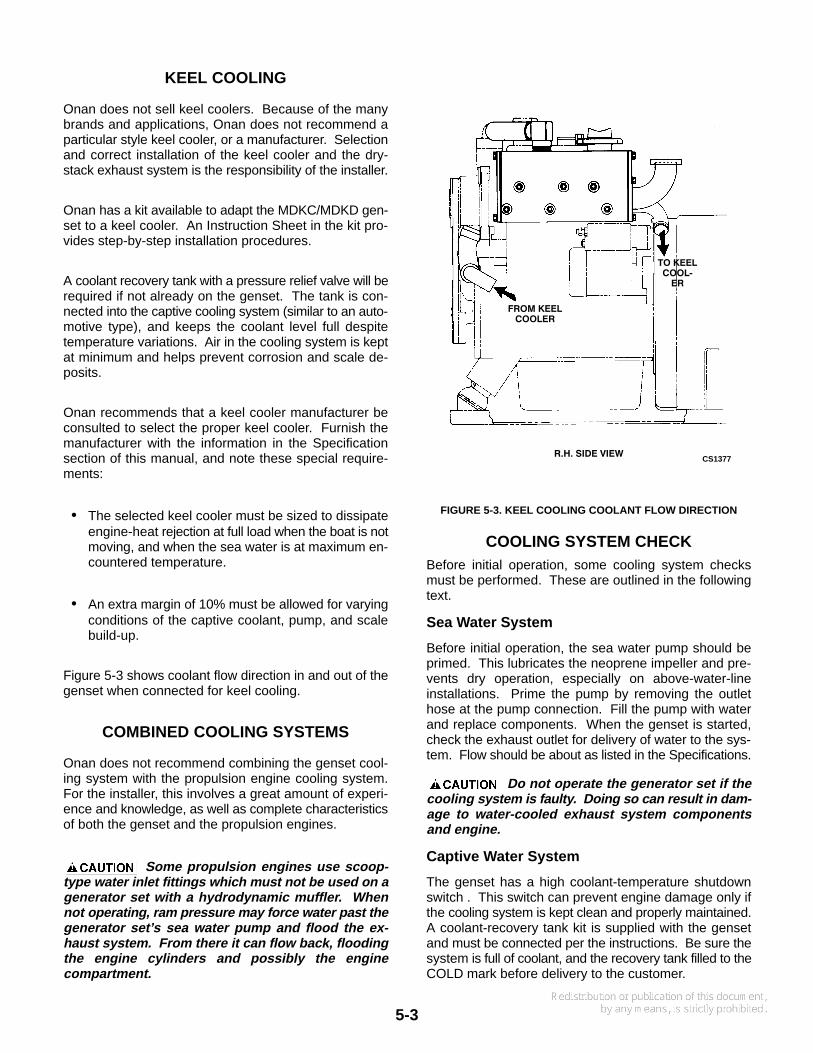
Figure 5-3 shows coolant flow direction in and out of thegenset when connected for keel cooling.
COMBINED COOLING SYSTEMS
Onan does not recommend combining the genset cool-ing system with the propulsion engine cooling system.For the installer, this involves a great amount of experi-ence and knowledge, as well as complete characteristicsof both the genset and the propulsion engines.
Some propulsion engines use scoop-type water inlet fittings which must not be used on agenerator set with a hydrodynamic muffler. Whennot operating, ram pressure may force water past thegenerator set’s sea water pump and flood the ex-haust system. From there it can flow back, floodingthe engine cylinders and possibly the enginecompartment.
R.H. SIDE VIEWCS1377
FROM KEELCOOLER
TO KEELCOOL−
ER
FIGURE 5-3. KEEL COOLING COOLANT FLOW DIRECTION
COOLING SYSTEM CHECKBefore initial operation, some cooling system checksmust be performed. These are outlined in the followingtext.
Sea Water System
Before initial operation, the sea water pump should beprimed. This lubricates the neoprene impeller and pre-vents dry operation, especially on above-water-lineinstallations. Prime the pump by removing the outlethose at the pump connection. Fill the pump with waterand replace components. When the genset is started,check the exhaust outlet for delivery of water to the sys-tem. Flow should be about as listed in the Specifications.
Do not operate the generator set if thecooling system is faulty. Doing so can result in dam-age to water-cooled exhaust system componentsand engine.
Captive Water System
The genset has a high coolant-temperature shutdownswitch . This switch can prevent engine damage only ifthe cooling system is kept clean and properly maintained.A coolant-recovery tank kit is supplied with the gensetand must be connected per the instructions. Be sure thesystem is full of coolant, and the recovery tank filled to theCOLD mark before delivery to the customer.

5-4
Use a 50-50 mixture of ethylene glycol and distilled wateras an engine coolant—even when freezing temperaturesare not expected. In addition to lowering the freezingpoint, it contains rust inhibitors that help prevent corro-sion and scale.
Do not exceed a 50-50 mixture of ethyl-ene glycol and water. A stronger mixture of ethyleneglycol will alter heat transfer properties of the cool-ant.
Filling the Cooling System
Verify that all drain cocks are closed and all hose clampssecure. Remove the cooling system pressure cap and
slowly fill the cooling system with the coolant mixture ref-erenced in the preceeding paragraph.
Leave the pressure cap off and start the engine. Astrapped air is expelled, the coolant level will drop andadditional coolant should be added. Replace the pres-sure cap when the coolant level is stable.
Gensets With Coolant Recovery Tank: Add coolantmixture to the COLD mark. Operate the genset until nor-mal operating temperature is maintained as observed onthe temperature gauge (option), or about 15 minutes ofoperation. Shut off the genset and let it cool down. Addcoolant to the recovery tank until level stabilizes at theCOLD mark. This may require several operation cyclesuntil air is purged from the system.
6-1
Section 6. Exhaust System
GENERAL
The installation of two water-cooled exhaust systems arecovered in this section. They are below-load waterlineand above-load waterline, and are covered under sepa-rate headings. All marine water-cooled exhaust systemsmust meet each of the following requirements.
Failure to meet these requirements andany applicable codes can result in severe propertydamage, personal injury or death.
• The entire exhaust system must be accessible so aperiodic visual and audible leakage-check can bedone by the operator.
• The exhaust system must be water cooled, and thewater injected as near to the genset as possible.
• The exhaust line must be installed to prevent backflow of water to the engine under any conditions; andthe exhaust outlet must be above the load waterline.Water backflow into the engine will damage it.
• The genset exhaust system must not be combinedwith the exhaust system of another engine.
• A flexible section of marine exhaust hose must beused near the engine to allow for engine movementand vibration during operation. All exhaust systemhoses must be CERTIFIED for marine use.
• The exhaust system must be of sufficient size to pre-vent excessive back pressure. See Back Pressuredata in this section.
• Make sure all sink, shower or other cabin drains areproperly trapped to prevent entrance of exhaust gas.
Backflow of water can cause severe en-gine damage and possible flooding of the boat. Makesure the hose from the exhaust manifold to the muf-fler slopes a minimum of 1/2 inch per linear foot (42mm/m). An uphill section between the exhaust man-ifold and muffler can cause backflow of water and isnot permissible—NO EXCEPTIONS.
Be sure that the vertical rise of the exhaust hose mea-sured from the bottom of the muffler to its peak is notmore than 48 inches (1.2 m) as shown in Figures 6-1 and6-2. The vertical rise must not slope—it must be verticalin relation to the base of the hydrodynamic muffler.
The exhaust tubing (on both above and below load-wa-terline installations) must be pitched downward to the
through-hull outlet fitting at a minimum downgrade of 1/2inch per linear foot (42 mm/m). There must also be a12-inch (305 mm) minimum drop from this peak to thethrough-hull outlet fitting as shown.
Provide adequate support for hose lengths to preventsagging, bending, and formation of water pockets. Theuse of automotive-type pipe hangers will help stop noisetransmission to the boat hull.
Allow space between the marine muffler and its mountingsurface by using spacers under the mounting flanges.This allows air circulation under the muffler and discour-ages condensation.
Material
Use material recommended by ABYC in ”Safety Stan-dard for Small Craft,” Section P1. The exhaust line mustbe at least as large as the engine exhaust manifold outlet.See the following section on Back Pressure.
Exhaust gas contains carbon monox-ide, an odorless, colorless, highly-poisonous gasthat presents the hazard of severe personal injury ordeath. Place special emphasis on the following:
• Be sure the flexible exhaust hose is designedand certified for marine exhaust-line use.
• Use two clamps at each end of all flexible ex-haust hose connections.
• Do not make sharp bends in the exhaust hose.• Position exhaust outlet to prevent backflow of
exhaust gases into the vessel.
Use flexible hose designed and CERTIFIED for marineexhaust-line use to ease installation, and for flexibility.The muffler must be at the lowest point of the entire ex-haust system. The muffler inlet should be at least 12inches (305 mm) below the engine exhaust manifold out-let. If this distance is less, backflow of water toward themanifold is more likely.
Use two clamps at each end of exhaust hoses as shownin Figures 6-1 and 6-2. The clamps must be corrosion re-sistant metal, and a minimum of 1/2 inch (12.7 mm) wide.They should be spaced at least one clamp-width apart,and at least one clamp-width from the end of the hose.Clamps depending solely on spring tension must not beused.
6-2
Back Pressure
Exhaust back pressure is an important measure of an ad-equate exhaust system. If the exhaust installation re-quires a long run of pipe (more than 30 feet [9 m] overall),back pressure should be checked. Exhaust back pres-sure of the genset should not exceed 3.0 inches (76 mm)of mercury (10 kPa).
Increase the exhaust pipe diameter from the muffler tothe hull outlet one standard pipe size for every 10 feet (3m) beyond 30 feet (9 m) of overall length.
Exhaust Cooling Water Injection
The neoprene impeller pump moves the sea waterthrough the cooling system and into the exhaust man-ifold. The injected water cools the exhaust and preventsexhaust system damage. A temperature operatedswitch on the exhaust manifold shuts down the genset ifoverheating occurs. The switch closes if temperaturereaches 221° to 239° F (105° to 115° C) and actuates theFault Reset breaker on the control panel.
If high exhaust-temperature shutdown occurs, the entireexhaust system should be checked for any signs of over-heating, especially the exhaust hoses. Replace defec-tive components immediately, and do not operate thegenset until system is repaired.
Inhalation of exhaust gas can cause se-vere personal injury or death. Do not operate thegenerator set after a high exhaust temperature shut-down until the entire exhaust system has beenchecked and serviced as required.
DO NOT USE SCOOP TYPE WATER IN-LET FITTINGS. Forward facing scoops can developsufficient ram pressure to force water past the gener-ator set’s sea water pump. This can flood the ex-haust system and the engine cylinders. This hap-pens when the generator set is not running and theboat is underway. Rear facing scoops develop vacu-um which can impede cooling water flow.
BELOW LOAD-WATERLINEINSTALLATION
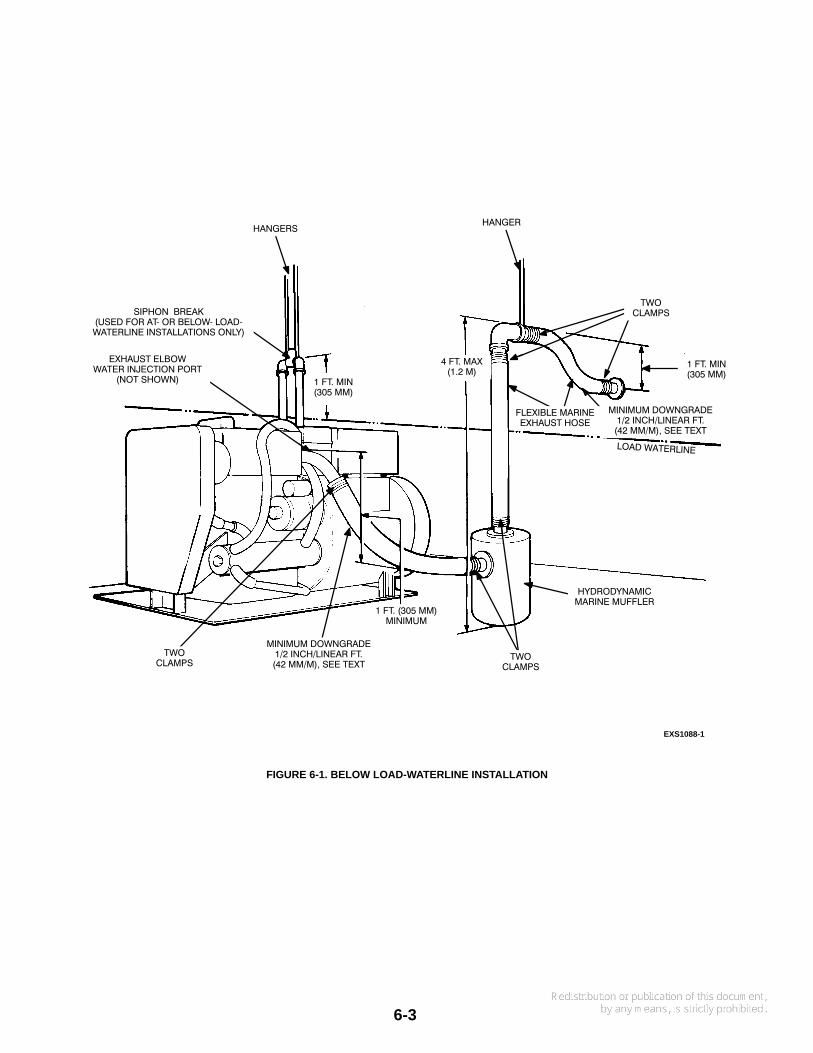
Figure 6-1 shows details of a recommended below load-waterline installation. Review and apply data from thepreceding GENERAL section, plus the following.
Siphon Break
Install a siphon break (anti-siphon) if the sea water injec-tion port on the exhaust manifold is at or below the load-waterline. The siphon break is a vacuum-operated ventvalve that opens the exhaust water discharge line to theatmosphere when the engine is not operating. The openvent valve prevents sea water (flotation water) from be-ing siphoned into the exhaust manifold and engine cylin-ders installed at or below load-waterline.
The siphon break hose ends connect to the exhaust el-bow water-injection port and the sea water outlet on theexhaust manifold.
Locate the siphon break in a vertical position at least 12inches (305 mm) above the load-waterline. See Figure6-1. Remote mounting is permissible within a 5 foot (1.5m) radius of the injection port. The vertical position andheight of the valve must be maintained.
The siphon break must be mounted vertically with thehose fitting pointing down. Use pipe strap material to se-cure the assembly to the frame or bulkhead. Be sure theslotted-opening in the siphon break valve is open to at-mospheric pressure. The valve will not function if theopening is closed in any way.
Failure to use a siphon break when theexhaust manifold injection-port is at or below theload-waterline will result in sea water damage to theengine and possible flooding of the boat.
6-3
EXS1088-1
1 FT. MIN(305 MM)
1 FT. MIN(305 MM)
TWOCLAMPS
HANGERHANGERS
SIPHON BREAK(USED FOR AT− OR BELOW− LOAD−WATERLINE INSTALLATIONS ONLY)
EXHAUST ELBOWWATER INJECTION PORT
(NOT SHOWN)
TWOCLAMPS
TWOCLAMPS
4 FT. MAX(1.2 M)
HYDRODYNAMICMARINE MUFFLER
1 FT. (305 MM)MINIMUM
MINIMUM DOWNGRADE1/2 INCH/LINEAR FT.(42 MM/M), SEE TEXT
FLEXIBLE MARINEEXHAUST HOSE
MINIMUM DOWNGRADE1/2 INCH/LINEAR FT.(42 MM/M), SEE TEXT
FIGURE 6-1. BELOW LOAD-WATERLINE INSTALLATION
6-4
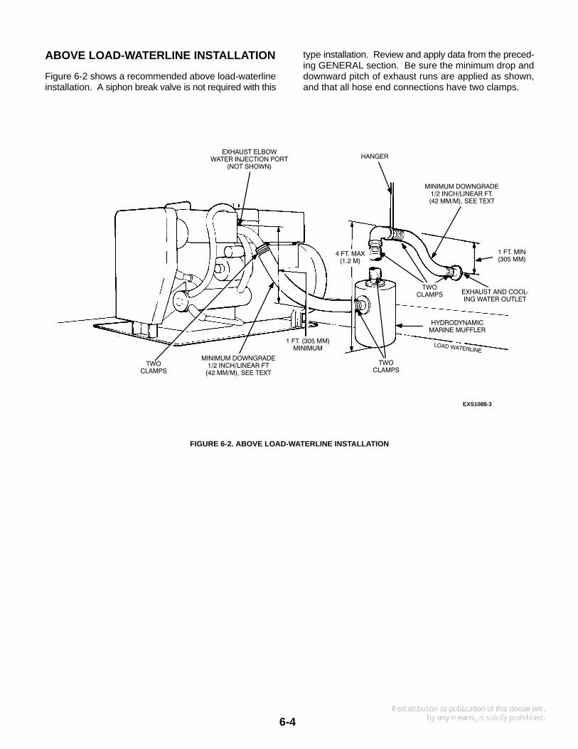
ABOVE LOAD-WATERLINE INSTALLATION
Figure 6-2 shows a recommended above load-waterlineinstallation. A siphon break valve is not required with this
type installation. Review and apply data from the preced-ing GENERAL section. Be sure the minimum drop anddownward pitch of exhaust runs are applied as shown,and that all hose end connections have two clamps.
EXS1088-3
HANGER
TWOCLAMPS
TWOCLAMPS
TWOCLAMPS
EXHAUST ELBOWWATER INJECTION PORT
(NOT SHOWN)
MINIMUM DOWNGRADE1/2 INCH/LINEAR FT.(42 MM/M), SEE TEXT
1 FT. MIN(305 MM)
EXHAUST AND COOL−ING WATER OUTLET
HYDRODYNAMICMARINE MUFFLER
MINIMUM DOWNGRADE1/2 INCH/LINEAR FT
(42 MM/M), SEE TEXT
4 FT. MAX(1.2 M)
1 FT. (305 MM)MINIMUM
FIGURE 6-2. ABOVE LOAD-WATERLINE INSTALLATION
7-1
Section 7. Fuel System
GENERAL
In all diesel engine installations, fuel system cleanlinessis of utmost importance. Make every effort to prevent en-trance of moisture or other contaminants. Carefullyclean all diesel fuel system components before installa-tion and putting the genset into operation.
Dirt or water in the fuel system is the ma-jor cause of diesel engine failure. A tiny piece of dirt,or a few drops of water in the injection system canstop the genset.
Fuel leakage in boats presents fire andexplosion hazards that can result in severe personalinjury or death. For this reason, it is important thatthe material, design, construction and installation ofall fuel system components meet the highest possi-ble standards. Use only products specified for ma-rine application.
If the propulsion engine uses diesel fuel, it is possible touse the same fuel tank for the genset. However, beforethat decision is made, the following factors must be con-sidered:
• Adequate fuel capacity for both engines. See Speci-fications section for genset requirements.
• The fuel returned to the tank after cooling the injec-tors is warm. To obtain maximum engine efficiency,fuel delivered to the injectors must be cool. The fueltank volume must be adequate to cool the returnedfuel.
• Distance of tank from the genset. The pump self-priming lift capacity is 48 inches (1.2 m). If this heightis exceeded, either an additional fuel pump or aseparate tank will be required.
FUEL LINES
Make sure all fuel lines are properly supported and con-nections tightened securely. The line should be sup-ported throughout its length with clips or straps spacedno more than 14 inches (355 mm). Use an approvedpipe-joint compound acceptable for use with diesel fuel atall thread fittings. Fuel distribution lines must have asfew connections as practicable, and be protected againstmechanical injury and vibration.
A flexible fuel line installed between the fuel tank and thegenset must meet USCG requirement 33CFR183.558and be stamped ”USCG TYPE A”. There cannot be an
electrical connection between the hose end fittings. Abad ground in the cranking circuit will cause a wire rein-forced hose to become hot, and ignite the fuel duringcranking. If a metallic fuel line is run into the genset com-partment, a length of flexible hose meeting the abovespecifications must be installed to absorb vibration of thegenset.
Ignition of fuel can cause fire and se-vere personal injury or death. Be sure the flexiblesection of fuel line used at the generator set meetsUSCG requirement 33CFR183.558 and is stamped”USCG TYPE A”.
Leakage of fuel in or around the genera-tor set compartment presents a hazard of fire or ex-plosion and can cause severe personal injury ordeath. Do not permit any flame, spark, cigarette, pilotlight, arcing equipment, or other ignition source nearthe generator set. The ventilation system must pro-vide a constant flow of air to safely expel all fuel va-pors.
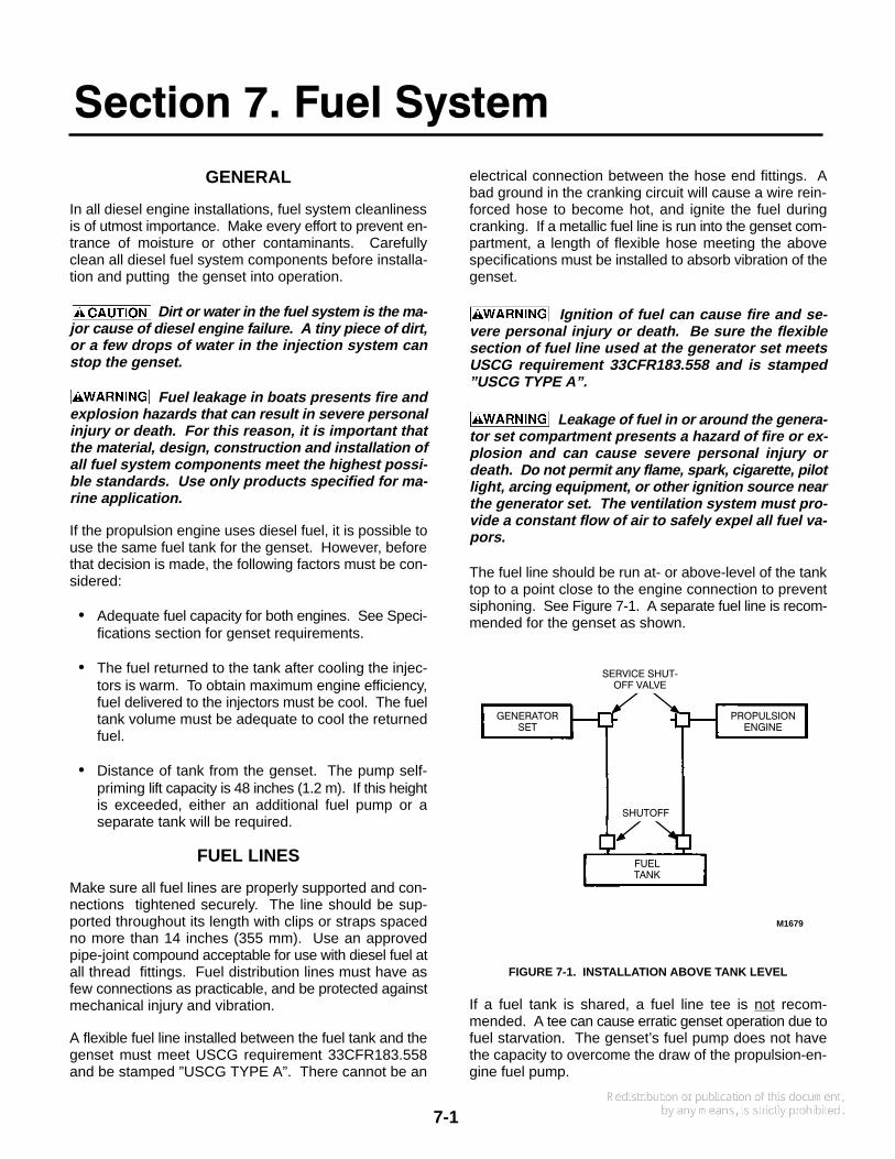
The fuel line should be run at- or above-level of the tanktop to a point close to the engine connection to preventsiphoning. See Figure 7-1. A separate fuel line is recom-mended for the genset as shown.
M1679
GENERATORSET
PROPULSIONENGINE
FUELTANK
SERVICE SHUT−OFF VALVE
SHUTOFF
FIGURE 7-1. INSTALLATION ABOVE TANK LEVEL
If a fuel tank is shared, a fuel line tee is not recom-mended. A tee can cause erratic genset operation due tofuel starvation. The genset’s fuel pump does not havethe capacity to overcome the draw of the propulsion-en-gine fuel pump.

7-2
This is true also of the return lines. Pressure from one en-gine could be higher than the other and force return fuelback into the lower-pressure engine injector. The returnline should enter the tank as far as possible from the sup-ply lines. Maximum back pressure at the injector fuel re-turn line fitting, shown in Figure 7-2, should not exceed 15psi (103 kPa). This pressure is a function of fuel flow rate,tank height, line size and length.
Never use galvanized or copper fuellines, fittings or fuel tanks with diesel fuel systems.Condensation in the tank and lines combines withthe sulfur in diesel fuel to produce sulfuric acid. Themolecular structure of the copper or galvanized linesor tanks reacts with the acid and contaminates thefuel.
FUEL RETURNLINE FITTING
INJECTIONPUMP
FUEL INLETFITTING FUEL FILTER
M-1526
FIGURE 7-2. ENGINE FUEL SYSTEM COMPONENTS
If the fuel tank fitting is large enough, a second, shorterdip tube may be installed as shown in Figure 7-3. The re-quired fittings can be built by a machine shop. Install ananti-siphon device at the tank fitting as shown.
M1679-2FUEL RETURNLINE FITTING
FUEL LINE TOPROPULSION
ENGINE ANTI−SIPHONDEVICE
FUEL LINETO GENSET
FIGURE 7-3. TWO FUEL LINES IN TANK FITTING
If the tank does not have an unused outlet, a new outletcan be installed. The metal tank must be removed tobraze or weld a new outlet fitting. This procedure re-quires the service of a welder familiar with the essentialsafety measures.
Ignition of fuel vapors can cause severepersonal injury or death. Welding a fuel tank, emptyor not, is extremely dangerous! Vapors may ignitecausing an explosion and fire. Have welding doneonly by experienced personnel.
SIPHON PROTECTION
When the fuel tank is installed above the engine level, ananti-siphon device is needed to prevent siphoning if theline breaks at a point below the fuel level. See Figure 7-4.This device can be installed at the tank withdrawal fitting,or at a location where the line from the tank will no longerremain above the fuel tank top level. The device can beeither a mechanical check valve, or an electric valve withmechanical override. The electric valve is connected toopen only when the engine fuel solenoid is on.
M1679-1
ANTI−SIPHON VALVE OR ELECTRICALLYOPERATED FUEL STOP VALVE
FUEL TANK
GENERATORSET
PROPULSIONENGINE
FIGURE 7-4. SIPHON PROTECTION
FUEL TANKS
A valve must be installed directly at the tank connectionto shut off fuel flow. This valve may be electrically ormanually operated. If electrically operated, it must be en-
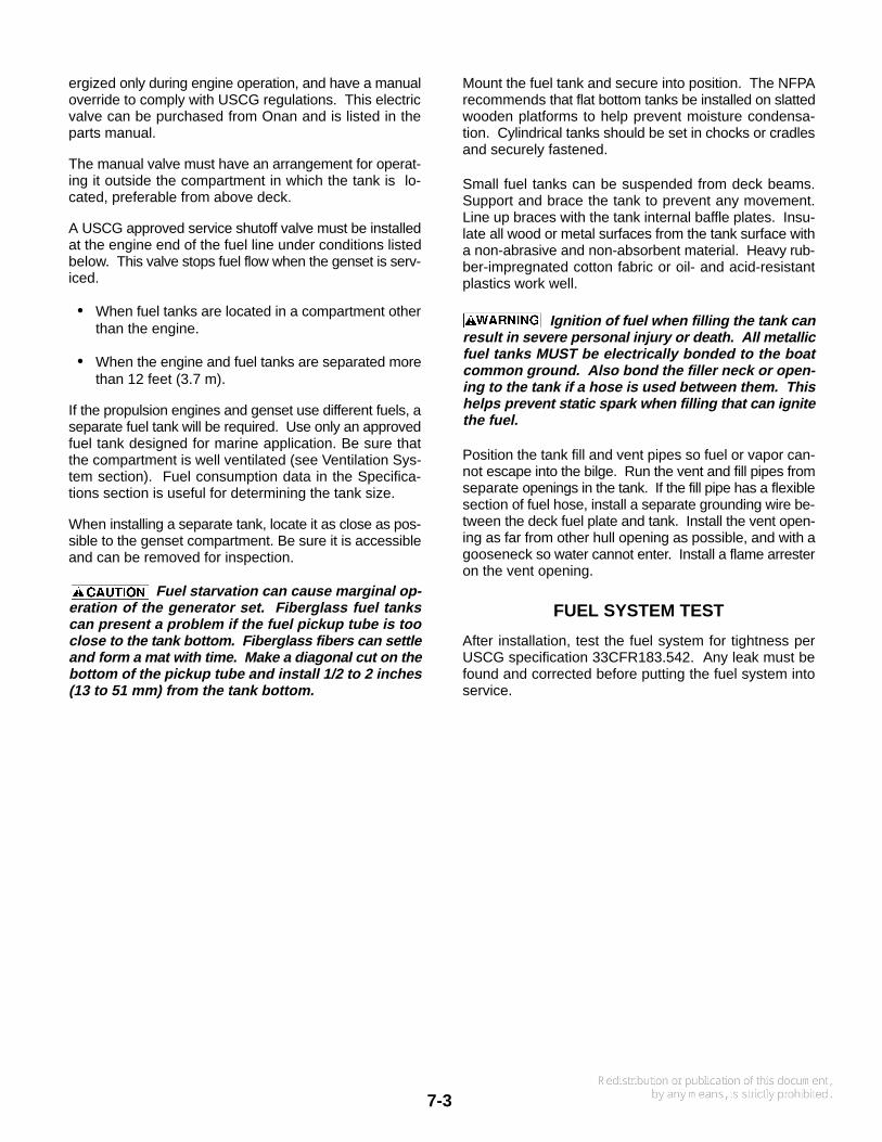
7-3
ergized only during engine operation, and have a manualoverride to comply with USCG regulations. This electricvalve can be purchased from Onan and is listed in theparts manual.
The manual valve must have an arrangement for operat-ing it outside the compartment in which the tank is lo-cated, preferable from above deck.
A USCG approved service shutoff valve must be installedat the engine end of the fuel line under conditions listedbelow. This valve stops fuel flow when the genset is serv-iced.
• When fuel tanks are located in a compartment otherthan the engine.
• When the engine and fuel tanks are separated morethan 12 feet (3.7 m).
If the propulsion engines and genset use different fuels, aseparate fuel tank will be required. Use only an approvedfuel tank designed for marine application. Be sure thatthe compartment is well ventilated (see Ventilation Sys-tem section). Fuel consumption data in the Specifica-tions section is useful for determining the tank size.
When installing a separate tank, locate it as close as pos-sible to the genset compartment. Be sure it is accessibleand can be removed for inspection.
Fuel starvation can cause marginal op-eration of the generator set. Fiberglass fuel tankscan present a problem if the fuel pickup tube is tooclose to the tank bottom. Fiberglass fibers can settleand form a mat with time. Make a diagonal cut on thebottom of the pickup tube and install 1/2 to 2 inches(13 to 51 mm) from the tank bottom.
Mount the fuel tank and secure into position. The NFPArecommends that flat bottom tanks be installed on slattedwooden platforms to help prevent moisture condensa-tion. Cylindrical tanks should be set in chocks or cradlesand securely fastened.
Small fuel tanks can be suspended from deck beams.Support and brace the tank to prevent any movement.Line up braces with the tank internal baffle plates. Insu-late all wood or metal surfaces from the tank surface witha non-abrasive and non-absorbent material. Heavy rub-ber-impregnated cotton fabric or oil- and acid-resistantplastics work well.
Ignition of fuel when filling the tank canresult in severe personal injury or death. All metallicfuel tanks MUST be electrically bonded to the boatcommon ground. Also bond the filler neck or open-ing to the tank if a hose is used between them. Thishelps prevent static spark when filling that can ignitethe fuel.
Position the tank fill and vent pipes so fuel or vapor can-not escape into the bilge. Run the vent and fill pipes fromseparate openings in the tank. If the fill pipe has a flexiblesection of fuel hose, install a separate grounding wire be-tween the deck fuel plate and tank. Install the vent open-ing as far from other hull opening as possible, and with agooseneck so water cannot enter. Install a flame arresteron the vent opening.
FUEL SYSTEM TEST
After installation, test the fuel system for tightness perUSCG specification 33CFR183.542. Any leak must befound and corrected before putting the fuel system intoservice.
8-1
Section 8. Electrical System
GENERAL
Installing the genset electrical system includes installingline circuit breakers and connecting the load, installingthe remote start control (if used), and connecting the bat-tery. The battery must always be connected last to avoidaccidental genset starting during the installation.
Accidental starting of the generator setduring installation creates a hazard of serious per-sonal injury or death. Do not connect the startingbattery until instructed to.
All wiring must meet Coast Guard, NFPA, and all otherapplicable codes. Have all wiring installed by a qualifiedelectrician. Wiring diagrams do not include customer-added components.
Be sure to seal all openings made for wiring so exhaust orfuel vapors cannot enter the living quarters. If flexible-metal conduit is used, it must be sealed internally at theend where it terminates within the junction box or panel-board. Flexible-metal conduit is not vapor-tight along itslength due to its unique construction.
Inhalation of exhaust gas or ignition offuel vapor can cause severe personal injury or death.Be sure to vapor-seal flexible metal conduit, and allopenings made during installation of the generatorset, with a silicone/rubber-based sealant.
Faulty electrical equipment can causeshock and severe personal injury or death. Use onlyapproved power supply assemblies, and never re-move the grounding pin from the power cord. Noground, or an incorrect ground, can cause the vesselto become electrically ”hot”.
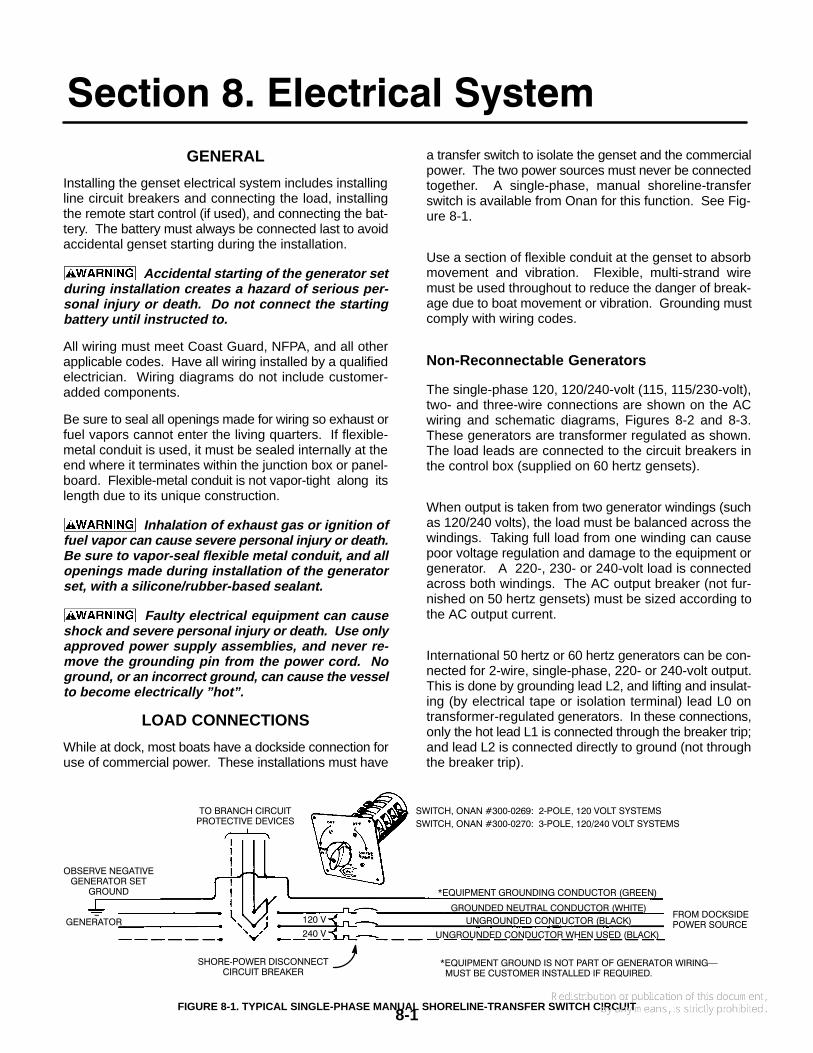
LOAD CONNECTIONS
While at dock, most boats have a dockside connection foruse of commercial power. These installations must have
a transfer switch to isolate the genset and the commercialpower. The two power sources must never be connectedtogether. A single-phase, manual shoreline-transferswitch is available from Onan for this function. See Fig-ure 8-1.
Use a section of flexible conduit at the genset to absorbmovement and vibration. Flexible, multi-strand wiremust be used throughout to reduce the danger of break-age due to boat movement or vibration. Grounding mustcomply with wiring codes.
Non-Reconnectable Generators
The single-phase 120, 120/240-volt (115, 115/230-volt),two- and three-wire connections are shown on the ACwiring and schematic diagrams, Figures 8-2 and 8-3.These generators are transformer regulated as shown.The load leads are connected to the circuit breakers inthe control box (supplied on 60 hertz gensets).
When output is taken from two generator windings (suchas 120/240 volts), the load must be balanced across thewindings. Taking full load from one winding can causepoor voltage regulation and damage to the equipment orgenerator. A 220-, 230- or 240-volt load is connectedacross both windings. The AC output breaker (not fur-nished on 50 hertz gensets) must be sized according tothe AC output current.
International 50 hertz or 60 hertz generators can be con-nected for 2-wire, single-phase, 220- or 240-volt output.This is done by grounding lead L2, and lifting and insulat-ing (by electrical tape or isolation terminal) lead L0 ontransformer-regulated generators. In these connections,only the hot lead L1 is connected through the breaker trip;and lead L2 is connected directly to ground (not throughthe breaker trip).
*EQUIPMENT GROUNDING CONDUCTOR (GREEN)
GROUNDED NEUTRAL CONDUCTOR (WHITE)
UNGROUNDED CONDUCTOR (BLACK)
UNGROUNDED CONDUCTOR WHEN USED (BLACK)
FROM DOCKSIDEPOWER SOURCE
120 V
240 V
SWITCH, ONAN #300−0269: 2−POLE, 120 VOLT SYSTEMS
SWITCH, ONAN #300−0270: 3−POLE, 120/240 VOLT SYSTEMS
TO BRANCH CIRCUITPROTECTIVE DEVICES
OBSERVE NEGATIVEGENERATOR SET
GROUND
GENERATOR
*EQUIPMENT GROUND IS NOT PART OF GENERATOR WIRING� MUST BE CUSTOMER INSTALLED IF REQUIRED.
SHORE−POWER DISCONNECTCIRCUIT BREAKER
FIGURE 8-1. TYPICAL SINGLE-PHASE MANUAL SHORELINE-TRANSFER SWITCH CIRCUIT

8-2
FIGURE 8-2. AC WIRING DIAGRAM, SINGLE-PHASE, TRANSFORMER REGULATION (PG. 1 OF 2)
8-3
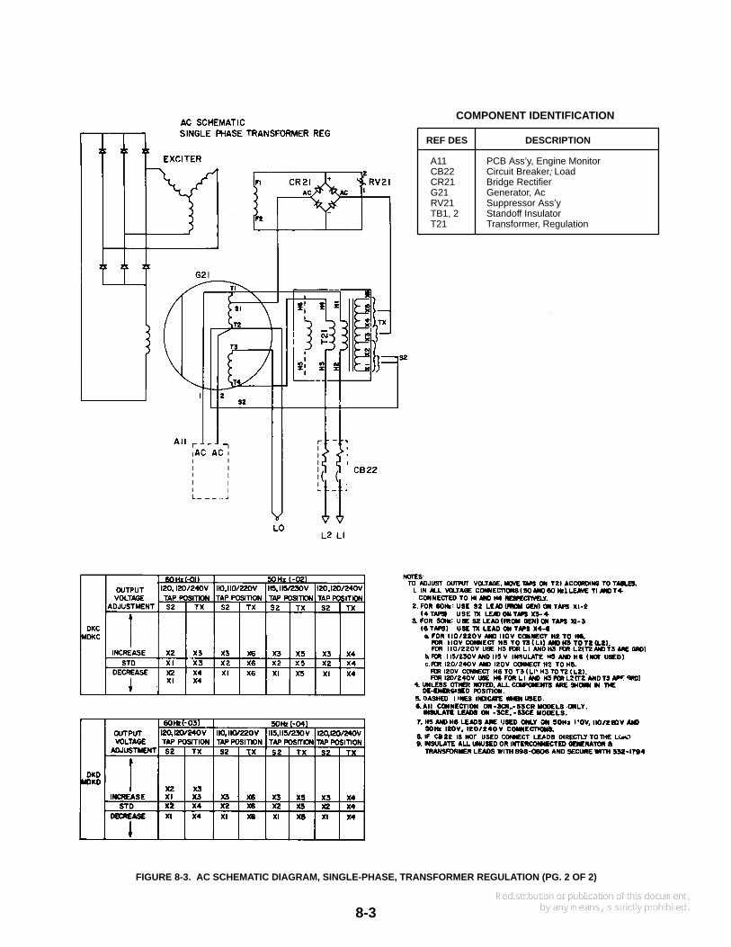
COMPONENT IDENTIFICATION
REF DES DESCRIPTION
A11 PCB Ass’y, Engine MonitorCB22 Circuit Breaker, LoadCR21 Bridge RectifierG21 Generator, AcRV21 Suppressor Ass’yTB1, 2 Standoff InsulatorT21 Transformer, Regulation
FIGURE 8-3. AC SCHEMATIC DIAGRAM, SINGLE-PHASE, TRANSFORMER REGULATION (PG. 2 OF 2)
8-4
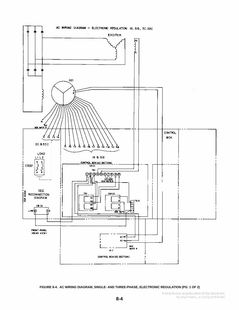
FIGURE 8-4. AC WIRING DIAGRAM, SINGLE- AND THREE-PHASE, ELECTRONIC REGULATION (PG. 1 OF 2)

8-5
COMPONENT IDENTIFICATION
REF DES DESCRIPTION
A11 PCB Ass’y, Engine MonitorCB21 Circuit Breaker, 3 AmpereCB22 Circuit Breaker, LoadG21 Generator, ACVR21 Voltage Regulator Ass’y
FIGURE 8-5. AC SCHEMATIC WIRING, SINGLE- AND THREE-PHASE, ELECTRONIC REGULATION (PG. 2 OF 2)
8-6
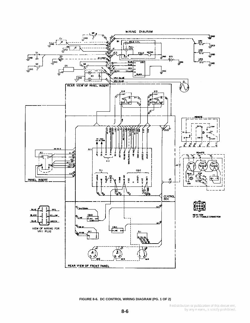
FIGURE 8-6. DC CONTROL WIRING DIAGRAM (PG. 1 OF 2)
8-7
COMPONENT IDENTIFICATION
REF DES DESCRIPTION
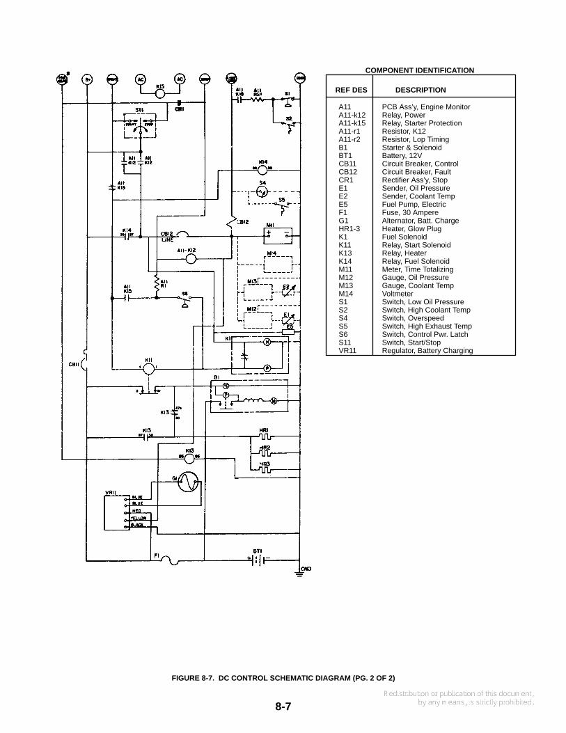
A11 PCB Ass’y, Engine MonitorA11-k12 Relay, PowerA11-k15 Relay, Starter ProtectionA11-r1 Resistor, K12A11-r2 Resistor, Lop TimingB1 Starter & SolenoidBT1 Battery, 12VCB11 Circuit Breaker, ControlCB12 Circuit Breaker, FaultCR1 Rectifier Ass’y, StopE1 Sender, Oil PressureE2 Sender, Coolant TempE5 Fuel Pump, ElectricF1 Fuse, 30 AmpereG1 Alternator, Batt. ChargeHR1-3 Heater, Glow PlugK1 Fuel SolenoidK11 Relay, Start SolenoidK13 Relay, HeaterK14 Relay, Fuel SolenoidM11 Meter, Time TotalizingM12 Gauge, Oil PressureM13 Gauge, Coolant TempM14 VoltmeterS1 Switch, Low Oil PressureS2 Switch, High Coolant TempS4 Switch, OverspeedS5 Switch, High Exhaust TempS6 Switch, Control Pwr. LatchS11 Switch, Start/StopVR11 Regulator, Battery Charging
FIGURE 8-7. DC CONTROL SCHEMATIC DIAGRAM (PG. 2 OF 2)
8-8
Reconnectable Generators
Reconnectable, multi-lead generators have wide rangesof single- or three-phase voltages. These generatorshave electronic regulation. The connections are shownon the AC wiring and schematic diagrams, Figures 8-4and 8-5.
REMOTE CONTROLS
Provision is made on the genset for connection of a re-mote control panel. A 9-pin remote connector (J3) on thecontrol box connects to a connector (J4) on the remotepanel. See Figure 8-6. Onan has two remote kits (with orwithout meters) complete with installation instructions.Also available are complete harness assemblies withend-connectors in 15-, 25-, and 45-foot (4.6, 7.6, and13.7 m) lengths. Call the Onan dealer or distributor forassistance in securing these items.
Additional control stations (without meters) can be addedif desired. The genset senders (temperature and oil pres-sure) can each control only one meter. If the genset con-trol box has meters, they must be disconnected to pre-vent erroneous readings at the remote panel. The electri-cal code does not allow the remote-control harness orwiring to be routed in the same conduit with AC wiring.
Interchanging the connections shownon the instruction sheet or the generator set wiringdiagram can cause equipment damage.
Be sure to seal all openings made for the wiring so ex-haust or fuel vapors cannot enter the living quarters. Ifflexible-metal conduit is used for remote wiring, it must besealed internally at the end where it terminates within thejunction box. Flexible-metal conduit is not vapor-tightalong its length due to its unique construction.
Inhalation of exhaust gas or ignition offuel vapor can cause severe personal injury or death.Be sure to vapor-seal flexible metal conduit and allopenings made during installation of the generatorset with a silicone/rubber-based sealant.
BATTERYGeneral
Always use a battery at least as large as specified. Thebattery should be installed close to the genset, prefer-ably in a separate compartment. The compartment mustbe well ventilated to prevent accumulation of explosivebattery gases.
Mount the battery in an acid resistant tray on a platformabove the floor. It must be secured to prevent shifting. Ifmounted in an engine compartment, always install a non-metallic cover to prevent battery damage and arcing from
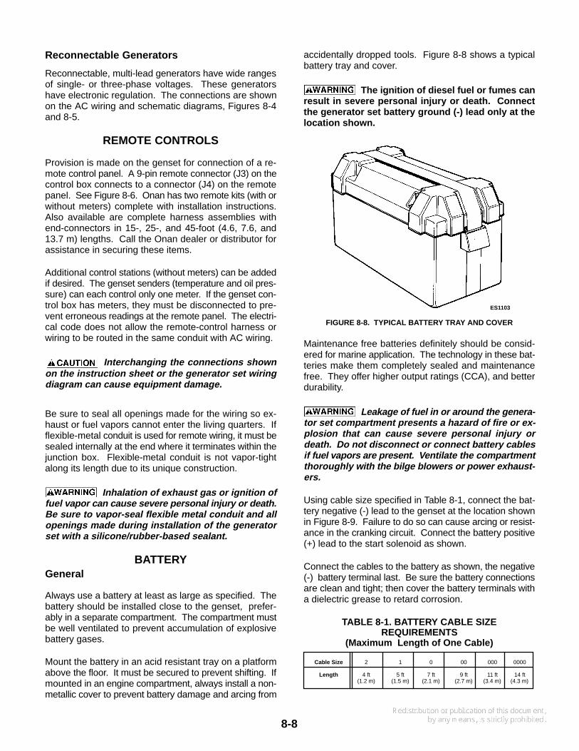
accidentally dropped tools. Figure 8-8 shows a typicalbattery tray and cover.
The ignition of diesel fuel or fumes canresult in severe personal injury or death. Connectthe generator set battery ground (-) lead only at thelocation shown.
ES1103
FIGURE 8-8. TYPICAL BATTERY TRAY AND COVER
Maintenance free batteries definitely should be consid-ered for marine application. The technology in these bat-teries make them completely sealed and maintenancefree. They offer higher output ratings (CCA), and betterdurability.
Leakage of fuel in or around the genera-tor set compartment presents a hazard of fire or ex-plosion that can cause severe personal injury ordeath. Do not disconnect or connect battery cablesif fuel vapors are present. V entilate the compartmentthoroughly with the bilge blowers or power exhaust-ers.
Using cable size specified in Table 8-1, connect the bat-tery negative (-) lead to the genset at the location shownin Figure 8-9. Failure to do so can cause arcing or resist-ance in the cranking circuit. Connect the battery positive(+) lead to the start solenoid as shown.
Connect the cables to the battery as shown, the negative(-) battery terminal last. Be sure the battery connectionsare clean and tight; then cover the battery terminals witha dielectric grease to retard corrosion.
TABLE 8-1. BATTERY CABLE SIZEREQUIREMENTS
(Maximum Length of One Cable)
Cable Size 2 1 0 00 000 0000
Length 4 ft 5 ft 7 ft 9 ft 11 ft 14 ft(1.2 m) (1.5 m) (2.1 m) (2.7 m) (3.4 m) (4.3 m)
8-9
ES1627-1
STARTER MOTOR
POSITIVE (+)BATTERY CABLE
NEGATIVE (−)BATTERY CABLE
COMMON BONDINGLEAD OR STRAP
TO VESSELCOMMON BONDING
CONDUCTOR
EITLOCKWASHER M10 CAPSCREW
EITLOCKWASHER
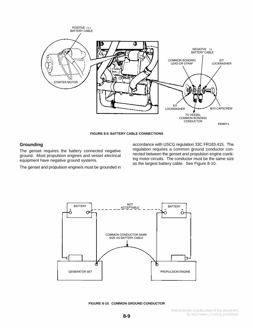
FIGURE 8-9. BATTERY CABLE CONNECTIONS
GroundingThe genset requires the battery connected negativeground. Most propulsion engines and vessel electricalequipment have negative ground systems.
The genset and propulsion engine/s must be grounded in
accordance with USCG regulation 33C FR183.415. Theregulation requires a common ground conductor con-nected between the genset and propulsion engine crank-ing motor circuits. The conductor must be the same sizeas the largest battery cable. See Figure 8-10.
BATTERY BATTERYNOT
ACCEPTABLE
GENERATOR SET PROPULSION ENGINE
COMMON CONDUCTOR SAMESIZE AS BATTERY CABLE
FIGURE 8-10. COMMON GROUND CONDUCTOR
8-10
The conductor prevents accidental passage of crankingcurrent through the fuel systems and smaller electricalconductors common to the engines. This can happen if acranking motor ground circuit becomes resistive oropens from corrosion, vibration, bad cable, etc. Do notconnect the battery negative lead at a genset locationother than shown in Figure 8-9.
Improper ground can cause severe per-sonal injury or death from fire or explosion. Be sureto install a common ground conductor between allon-board cranking circuits.
BONDING
The genset must be bonded to the vessel common-bond-ing conductor with a bonding lead or strap attached to theengine block (same location as the negative batterycable). See Figure 8-9 for hardware used and the properassembly.
If a metallic fuel line is installed between the fuel tank andthe genset shutoff valve, it too must be bonded to the ves-sel common-bonding conductor.

9-1
Section 9. Final Installation Checks
INSTALLATION CHECKS
Before trying to start the genset, determine that the instal-lation is complete by answering affirmatively the follow-ing questions:
• Is the exhaust system secure and all connectionstight?
• Is a flexible section of exhaust hose used betweenthe genset and muffler?
• Is all exhaust hose certified for marine exhaust ap-plication, and adequately supported and protected?
• Is the exhaust outlet terminated away from windows,vents or other openings that might allow exhaustgases to enter the vessel, or be pulled into the vesselwhen in motion?
• Are the AC generator and load wires securely andcorrectly connected to the circuit breaker?
• Are the battery cables connected correctly and se-curely at the genset and battery?
• Has crankcase oil been added to the engine, and atthe correct level? See the Maintenance section ofthe Operator’s Manual.
Oil, coolant, and fuel have beendrained from the engine at the factory prior toshipment. Operation without oil and coolant willdamage the engine.
INITIAL STARTING AND CHECKS
Refer to the Operator’s Manual before trying to start thegenset. Make sure the fuel shutoff valve and sea watercock are open. Operating the sea water pump withoutwater will ruin the neoprene impeller.
• Start the genset by holding the Start/Stop switch inStart position. The genset should start within a fewseconds. If not, check fuel supply and shutoffvalve/s.
• Check water flow at the hull exhaust outlet, and op-eration of the genset. Refer to Operator’s Manual forproper parameters.
• Check the exhaust system for leaks—visually andaudibly. Note the security of the exhaust system
supports. If any leaks are found, shut down the gen-set immediately and repair.
Exhaust gas is deadly. For this rea-son, shut down the generator set immediately ifan exhaust leak or exhaust component needsrepair. Do not run the generator set until the ex-haust system is repaired.
• Check the genset for fuel, oil and coolant leaks. Ifany are found, shut down the genset and repair theleak before making any more checks.
• Connect an accurate AC voltmeter and frequencymeter across two line terminals. Apply load to thegenerator and check the output.
Output frequency is determined by engine speed andnormally does not require adjustment. Verify that fre-quency is correct before making voltage adjustments.Call an authorized Onan distributor or dealer for assis-tance if needed.
VOLTAGE ADJUSTMENT
If the voltage is not within specs, it can be adjusted usingthe following procedures for either Transformer or Elec-tronic regulation.
High voltages within the control cabinetcan cause severe personal injury or death. Proceedwith care and do not touch electrical contacts withany tool, clothing, jewelry or body part.
Magnetic Regulation
1. With the genset running, note if voltage needs to beincreased or decreased.
2. Stop the genset. Disconnect the negative (-) bat-tery cable before proceeding.
Accidental starting of the genera-tor set can cause severe personal injury ordeath. Disconnect the negative (-) battery cablebefore adjusting the regulator transformer taps.
3. Move taps of transformer T21 as shown on the chartin Figure 8-3.
4. Reconnect the battery cable. Operate the gensetand recheck output voltage. If necessary, repeat theabove steps. The genset is now ready for operation.
9-2
Electronic Regulation
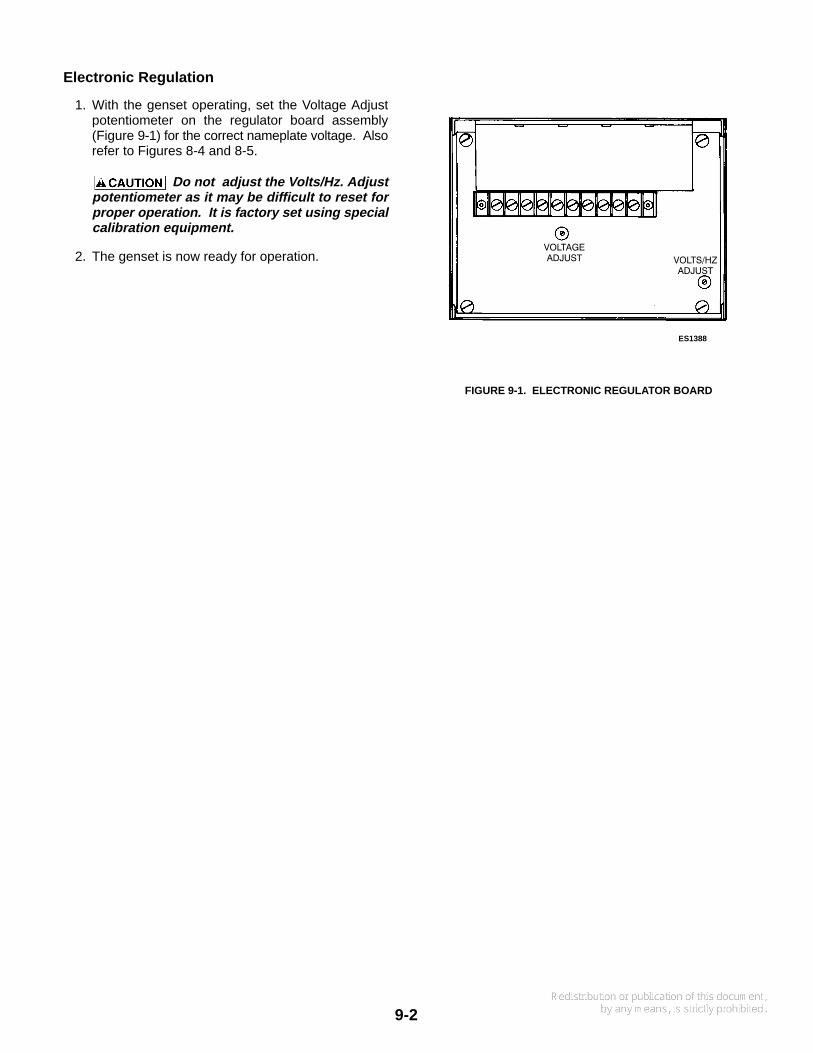
1. With the genset operating, set the Voltage Adjustpotentiometer on the regulator board assembly(Figure 9-1) for the correct nameplate voltage. Alsorefer to Figures 8-4 and 8-5.
Do not adjust the Volts/Hz. Adjustpotentiometer as it may be difficult to reset forproper operation. It is factory set using specialcalibration equipment.
2. The genset is now ready for operation.
ES1388
VOLTAGEADJUST VOLTS/HZ
ADJUST
FIGURE 9-1. ELECTRONIC REGULATOR BOARD

Notes

Cummins Power Generation1400 73rd Avenue N.E.Minneapolis, MN 55432763-574-5000Fax: 763-528-7229
Cummins and Onan are registered trademarks of Cummins Inc.


![Onan Generator Operating Manual 981-0120[1]](https://img.pdfslide.net/doc/110x75/55cf943c550346f57ba08485/onan-generator-operating-manual-981-01201.jpg)