Embed Size (px)
Citation preview
Prism® PI by StoneLInstallation, Maintenance andOperating instructions
7 PI 70 en • 09/2018
StoneL publication 105431revB
7 PI 70 en2 | Prism PI
StoneL publication 105431revB
Read these instructions first!These instructions provide information about safe handling and operation of the Prism PI by StoneL. If you require additional assistance, please contact the manufacturer or manufacturer’s representative. Addresses and phone numbers are printed on the back cover.Save these instructions.
Subject to change without notice.All trademarks are property of their respective owners.
Table of contents1 General 3
1.1 Introduction 31.2 Title plate markings 31.3 CE markings 31.4 Recycling and disposal 31.5 Safety precautions 31.6 Assembly drawing 41.7 Specifications for all models 41.8 Pneumatic valve specifications 51.9 Pneumatic valve schematics 51.10 Dimensions 6
2 Assembly and mounting 72.1 Instructions 72.2 Prism PI assembly figure 8
3 Maintenance, repair and installation 93.1 Maintenance and repair 93.2 Installation 93.3 Special conditions of use 9
4 Function specific details 104.1 Sensor/switching modules 10
4.1.1 SST NO sensor (33S) 104.1.2 NAMUR sensor (45S) 114.1.3 Expeditor, standard stroke (80S & 80W) 134.1.4 Expeditor, long stroke (81S & 81W) 14
4.2 Valve communication terminals (VCT) 164.2.1 VCT with DeviceNet™ communication (92S & 92W) 164.2.2 VCT with AS-Interface communication (96S & 96W) 184.2.3 VCT with AS-Interface communication and extended addressing (97S & 97W) 20
5 Wireless Link user guide 225.1 Getting started 225.2 Home screen 225.3 Locked screen 225.4 Device detail screen 235.5 More information screen 245.6 Diagnostics screen 255.7 Federal Communication Commission (FCC) statement 26
6 Model/Type code 27
7 Regulatory, specific conditions of use, and product marking 28
8 Appendix 308.1 Controlled installation drawings 30
StoneL publication 105431revB
7 PI 70 en Prism PI | 3
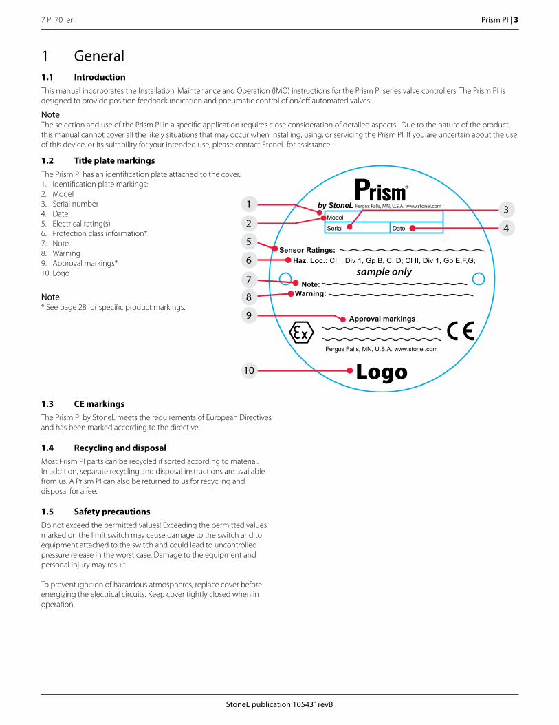
Logo
Warning:Note:
Sensor Ratings:Haz. Loc.: CI I, Div 1, Gp B, C, D; CI II, Div 1, Gp E,F,G;
sample only
Approval markings
Serial
Model
Date
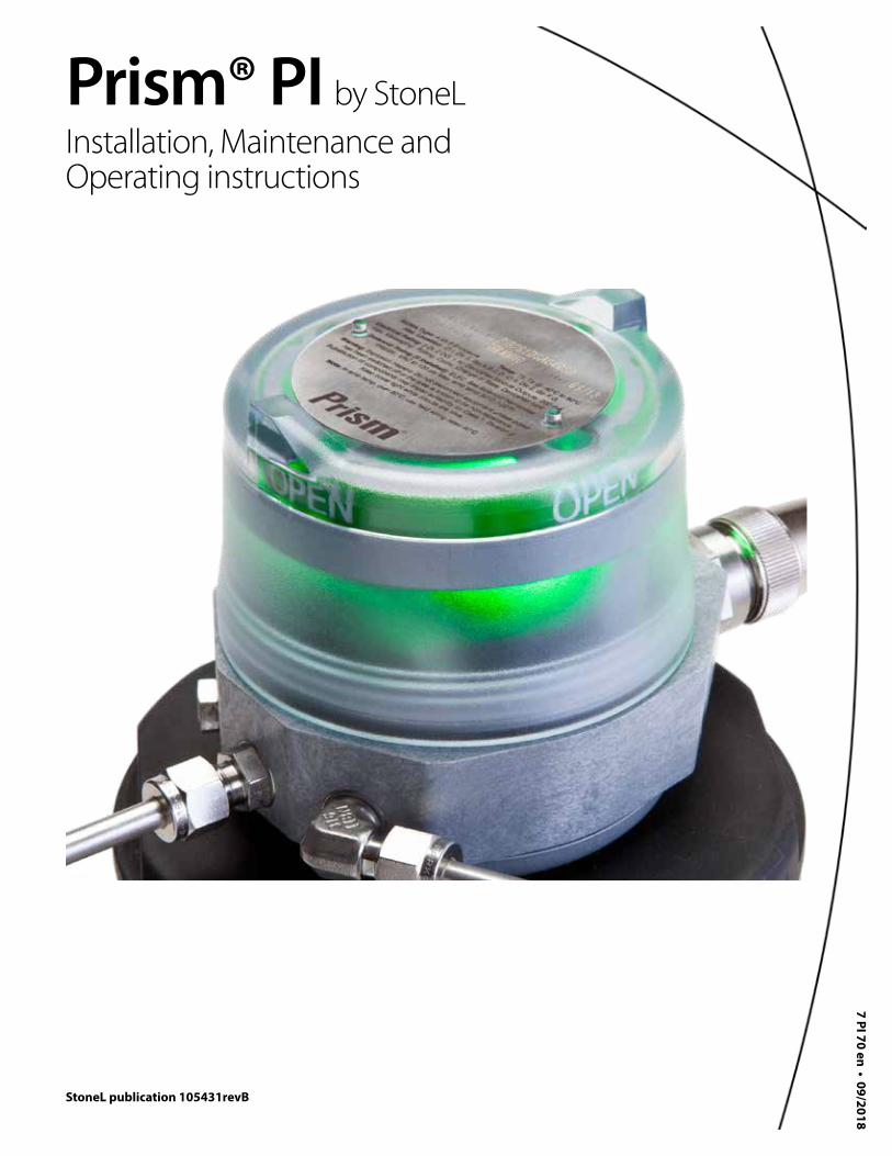
1.2 Title plate markingsThe Prism PI has an identification plate attached to the cover.1. Identification plate markings:2. Model3. Serial number4. Date5. Electrical rating(s)6. Protection class information*7. Note8. Warning9. Approval markings*10. Logo
Note* See page 28 for specific product markings.
1 General1.1 IntroductionThis manual incorporates the Installation, Maintenance and Operation (IMO) instructions for the Prism PI series valve controllers. The Prism PI is designed to provide position feedback indication and pneumatic control of on/off automated valves.
NoteThe selection and use of the Prism PI in a specific application requires close consideration of detailed aspects. Due to the nature of the product, this manual cannot cover all the likely situations that may occur when installing, using, or servicing the Prism PI. If you are uncertain about the use of this device, or its suitability for your intended use, please contact StoneL for assistance.
1.3 CE markingsThe Prism PI by StoneL meets the requirements of European Directives and has been marked according to the directive.
1.4 Recycling and disposalMost Prism PI parts can be recycled if sorted according to material. In addition, separate recycling and disposal instructions are available from us. A Prism PI can also be returned to us for recycling and disposal for a fee.
1.5 Safety precautionsDo not exceed the permitted values! Exceeding the permitted values marked on the limit switch may cause damage to the switch and to equipment attached to the switch and could lead to uncontrolled pressure release in the worst case. Damage to the equipment and personal injury may result.
To prevent ignition of hazardous atmospheres, replace cover before energizing the electrical circuits. Keep cover tightly closed when in operation.
10
5
8
1
7
3
9
6
2 4
7 PI 70 en4 | Prism PI
StoneL publication 105431revB
Specifications
Materials of construction
Cover Clear polycarbonate
Housing & mounting system Fiber reinforced polycarbonate and stainless steel
Fasteners Stainless steel
Mounting system Fiber reinforced polycarbonate and stainless steel
Seals Buna N
Valve manifold Polycarbonate with stainless steel reinforced 1/8“ NPT porting
Trigger (magnetic) Polysulfone with black chromated zinc reinforcement
Operating life Over 1 million cycles
Operating temperature rangeUnit without solenoidUnit with solenoid
-20° C to 60° C (-4° F to 140 ° F)See 1.8 Pneumatic valve specifications
Enclosure protection Type 4, 4X, 6 and IP66 / IP67
Warranty
Sensing & communication module
Five years
Mechanical components Two years
Unit weights
Standard stroke 0.77 kg / 1.7 lb
Long stroke 0.95 kg / 2.1 lb
Unit dimensions
Standard stroke no visual indicator Unit heightCover removal clearance
84.1 mm [3.31 in]25 mm [1 in]
Standard stroke with visual indicator Unit heightCover removal clearance
107.9 mm [4.01 in]25 mm [1 in]
Long stroke Unit heightCover removal clearance
163.3 mm [6.43 in]70 mm [2.75 in]
Position sensing
Accuracy 1.0 mm [0.04 in]
Repeatability 0.5 mm [0.02 in]
Setting buffer (factory settings) Open - 25% of stroke lengthClosed - 25% of stroke length up to 3.2 mm [0.125 in]
Deadband (factory settings) Open - 30% of stroke length (variable; based on actual stroke)Closed - 30% of stroke length or 3.8 mm [0.15 in] (whichever is less)
Environmental conditions
Location Indoor and outdoor
Maximum altitude 5000 m
Maximum humidity 90%
Pollution degree 4
Ratings and approvals* See page 28 or StoneL.com/approvals
* Only models listed on StoneL’s official website are approved per specific rating.
1.7 Specifications for all modelsSee page 10 for function specific details.
6
8
5
9
4
10
11
7
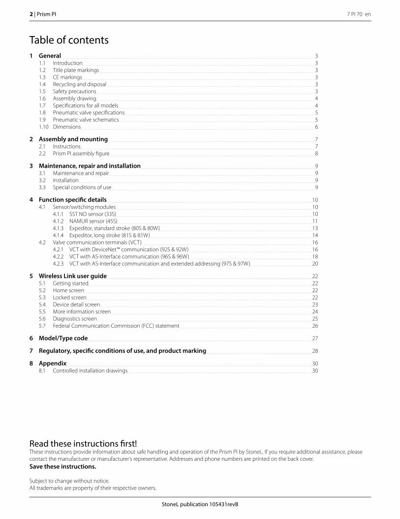
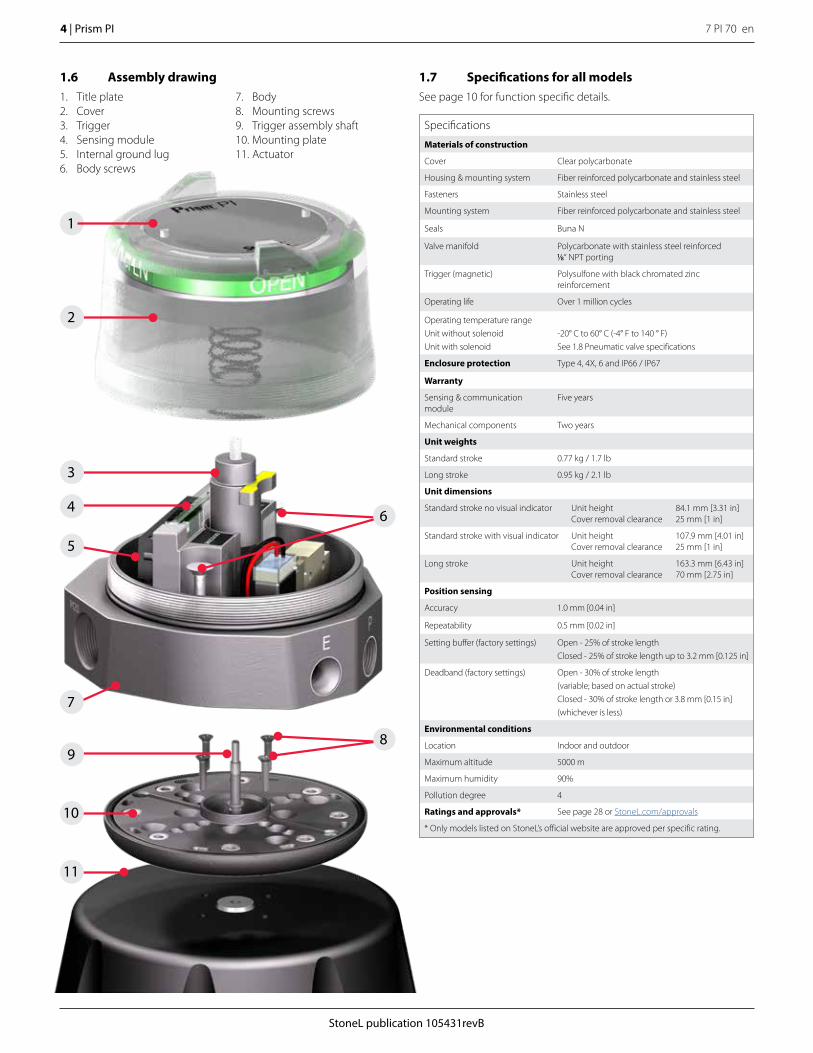
1.6 Assembly drawing1. Title plate 2. Cover3. Trigger4. Sensing module5. Internal ground lug6. Body screws
7. Body8. Mounting screws9. Trigger assembly shaft10. Mounting plate11. Actuator
1
2
3
StoneL publication 105431revB
7 PI 70 en Prism PI | 5
Specifications
General pneumatic specifications
Configuration 3-way, 2-position, spring return
Type Direct acting
Porting 1/8” NPT (stainless steel reinforced)
Medium Air or inert gas
Medium temperature range (TS) -40° C to 80° C (-40° F to 176 ° F)
Operating pressure 25 psi to 120 psi (1.72 to 9.65 bar)
Operating life 1 million cycles
Manual override Internal momentary
Solenoid coil specifications1K (33_, 92_, 96_, 97_)Operating voltagePower consumptionFlow ratingOperating temperatureFiltration requirements
24 VDC1.0 watt0.2 Cv (Kv = 0.17 based on flow m3/hr) -10° C to 50° C (14° F to 122° F)40 microns
2K (80_, 81_,)Operating voltagePower consumptionFlow ratingOperating temperatureFiltration requirements
24 VDC1.0 watt0.2 Cv (Kv = 0.17 based on flow m3/hr) -10° C to 50° C (14° F to 122° F)40 microns
1M (33_)Operating voltage Power consumptionFlow ratingOperating temperatureFiltration requirements
120 VAC 50/60 Hz1.0 watt0.2 Cv (Kv = 0.17 based on flow m3/hr) -10° C to 50° C (14° F to 122° F)40 microns
1N (33_)Operating voltage Power consumption
Flow ratingInrush current
Operating temperatureFiltration requirements
20 - 125 VAC 50/60 Hz; 20 - 55 VDC12 mA @ 20 - 125 VAC (1.0 watt typical)20 mA @ 20 - 55 VDC (0.5 watts typical)0.1 Cv (Kv = 0.08 based on flow m3/hr) 3.75 A @ 125 VAC (typical)0.15 A @ 24 VDC (typical)-20° C to 60° C (-4° F to 140 ° F)50 microns
1N (92_, 96_, 97_)Operating voltage Power consumptionFlow ratingOperating temperatureFiltration requirements
24 VDC0.5 watts0.1 Cv (Kv = 0.08 based on flow m3/hr) -20° C to 60° C (-4° F to 140 ° F)50 microns
1N (45_)Operating voltage Power consumptionFlow ratingOperating temperatureFiltration requirements Entity parameters
18 - 28 VDC0.3 watts0.1 Cv (Kv = 0.08 based on flow m3/hr) -20° C to 60° C (-4° F to 140 ° F)50 micronsUi=28 VDC, Ii=120 mA, Ci=3 nF, Li=0 mH, Pi=0.84 W
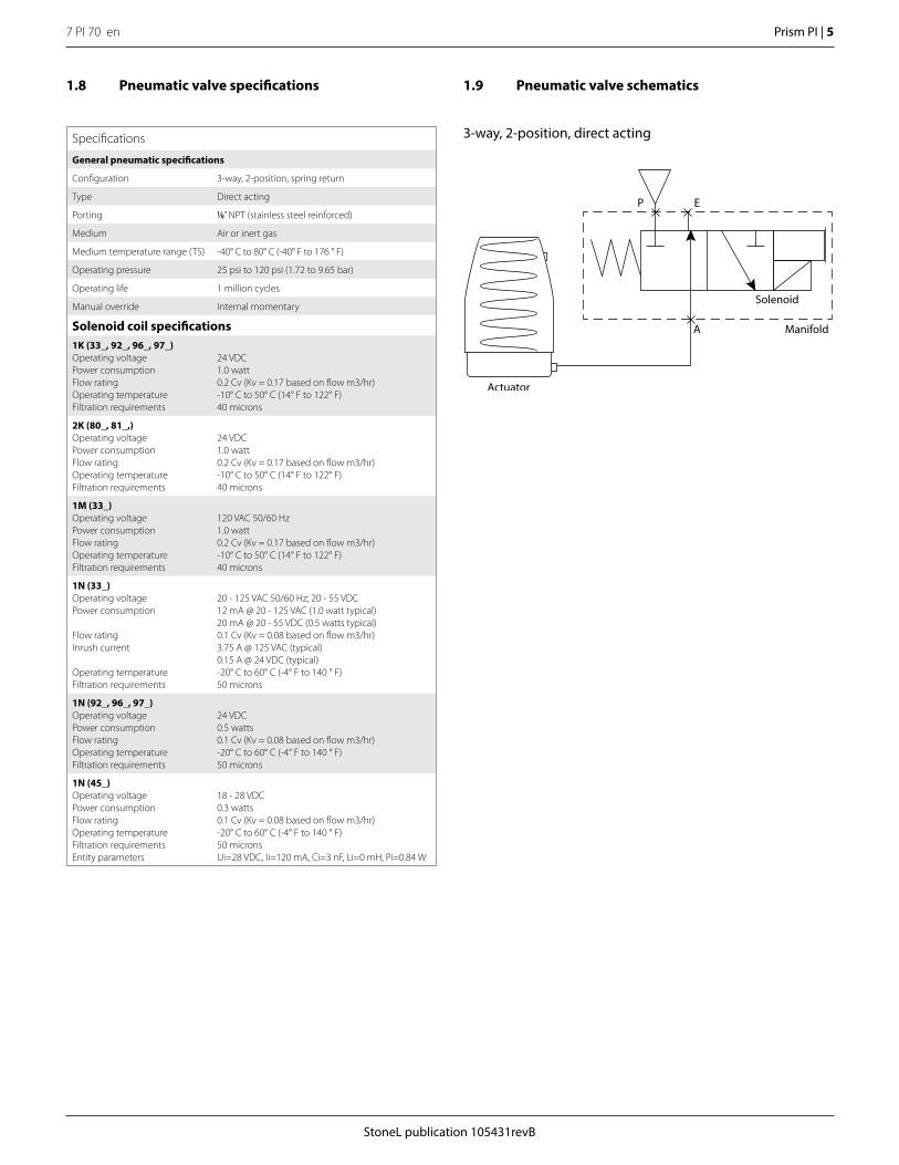
1.8 Pneumatic valve specifications 1.9 Pneumatic valve schematics
3-way, 2-position, direct acting
P E
A
Actuator
Manifold
Solenoid
7 PI 70 en6 | Prism PI
StoneL publication 105431revB
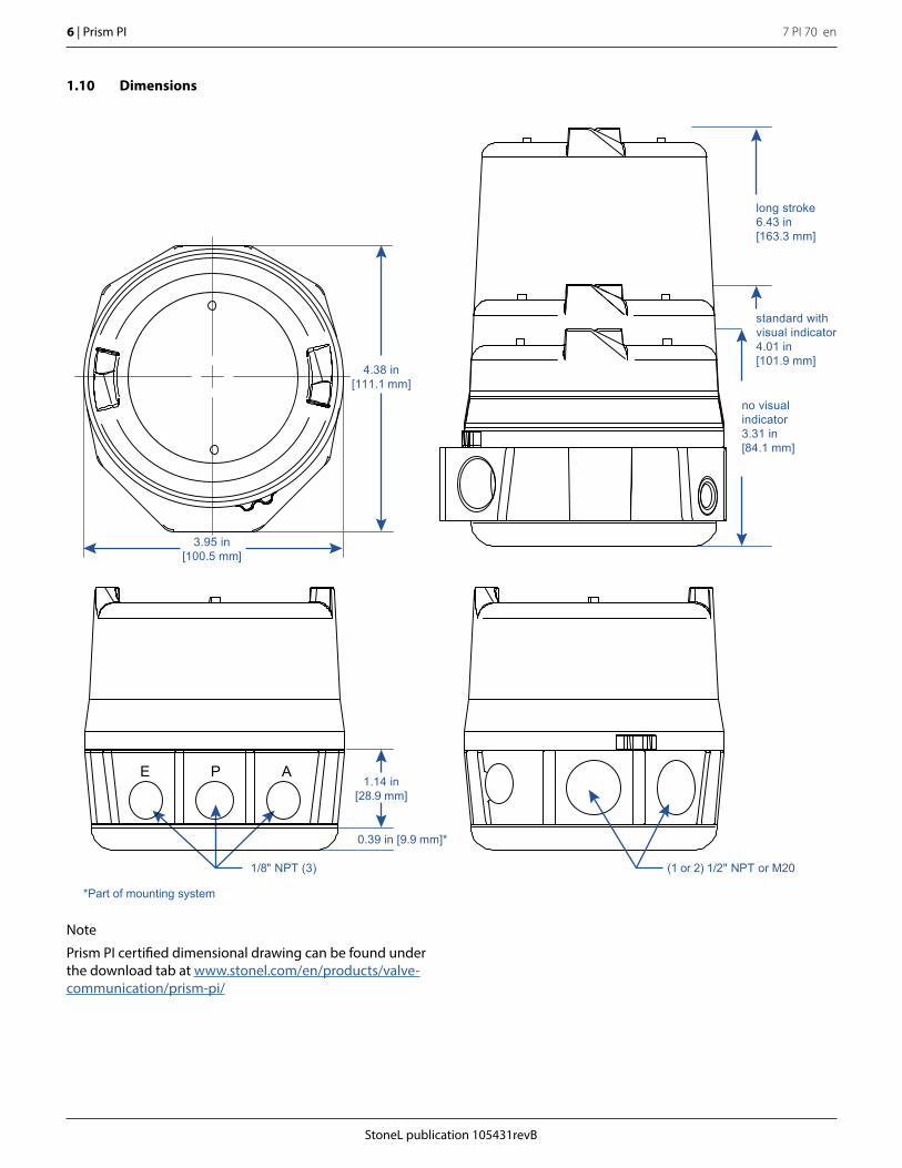
1.10 Dimensions
Note
Prism PI certified dimensional drawing can be found under the download tab at www.stonel.com/en/products/valve-communication/prism-pi/
(1 or 2) 1/2" NPT or M201/8" NPT (3)
E P A1.14 in
[28.9 mm]
0.39 in [9.9 mm]*
*Part of mounting system
no visual indicator3.31 in[84.1 mm]
standard with visual indicator4.01 in[101.9 mm]
long stroke6.43 in[163.3 mm]
3.95 in[100.5 mm]
4.38 in[111.1 mm]
StoneL publication 105431revB
7 PI 70 en Prism PI | 7
2 Assembly and mounting2.1 Instructions
StepsRefer to Prism PI assembly figure on page 8 when performing mounting and assembly procedures. Prism PI unit and mounting kit are supplied separately. From Prism PI shipping container, ensure items A, and F are present. From the mounting kit, ensure items G, H, I, and J are present.1. From the mounting kit package, locate the trigger shaft (Item G),
Prism mounting plate (Item J), and mounting plate fasteners (Item H). Ensure unit O-ring (Item I) and mounting plate O-ring (Item K) are present in the mounting plate.
2. Thread the trigger shaft into the actuator (Item L) (it is recommended that a drop of blue Loctite® be used on the trigger shaft threads). Tighten to approximately 15 - 20 in.lbs (1.7 - 2.3 Nm) with a small adjustable wrench.
3. Place the mounting plate onto the actuator and fasten down with provided screws (2-4). (use of blue Loctite® on these screws is optional). Tighten to approximately 15 - 20 in.lbs (1.7 - 2.3 Nm).
4. Take off cover (Item B) and remove the trigger assembly (Item F) from within the unit.
5. Place Prism PI unit (Item A) onto the mounting plate in the orientation desired (Prism PI body can be rotated on the mounting plate in 45° increments). Tighten the two body screws (Item D) with a M3 allen wrench to approximately 25 - 30 in.lbs (2.8 - 3.4Nm).
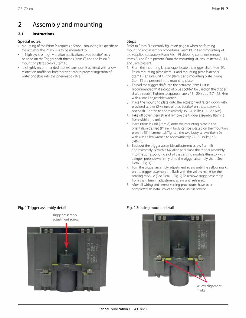
6. Back out the trigger assembly adjustment screw (Item E) approximately 1/8” with a M2 allen and place the trigger assembly into the corresponding slot of the sensing module (Item C), with a finger, press down firmly onto the trigger assembly shaft (See Detail - Fig. 1).
7. Turn the trigger assembly adjustment screw until the yellow marks on the trigger assembly are flush with the yellow marks on the sensing module (See Detail - Fig. 2) To remove trigger assembly from shaft, turn in adjustment screw until released.
8. After all wiring and sensor setting procedures have been completed, re-install cover and place unit in service.
Special notes:• Mounting of the Prism PI requires a StoneL mounting kit specific to
the actuator the Prism PI is to be mounted to.• In high cycle or high vibration applications, blue Loctite® may
be used on the Trigger shaft threads (Item G) and the Prism PI mounting plate screws (Item H).
• It is highly recommended that exhaust port E be fitted with a low restriction muffler or breather vent cap to prevent ingestion of water or debris into the pneumatic valve.
Fig. 2 Sensing module detailFig. 1 Trigger assembly detail
Trigger assembly adjustment screw
Yellow alignment marks
7 PI 70 en8 | Prism PI
StoneL publication 105431revB
E P
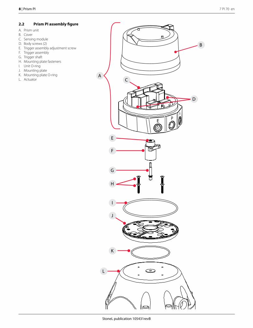
2.2 Prism PI assembly figureA. Prism unitB. CoverC. Sensing moduleD. Body screws (2)E. Trigger assembly adjustment screwF. Trigger assemblyG. Trigger shaftH. Mounting plate fastenersI. Unit O-ringJ. Mounting plate K. Mounting plate O-ringL. Actuator
F
E
G
H
L
K
J
C
I
D
B
A
StoneL publication 105431revB
7 PI 70 en Prism PI | 9
3 Maintenance, repair and installation3.1 Maintenance and repairNo routine maintenance of Prism units is required when installed in environments for which they are designed. If installed in severe environments, pneumatic components may require replacement at more frequent intervals for maximum performance. Repair of Prism units must be done by StoneL or by qualified personnel that are knowledgeable about the installation of electromechanical equipment in hazardous areas. All parts needed for repair must be purchased through a StoneL authorized distributor to maintain warranty and to ensure the safety and compliance of the equipment.
3.2 Installation
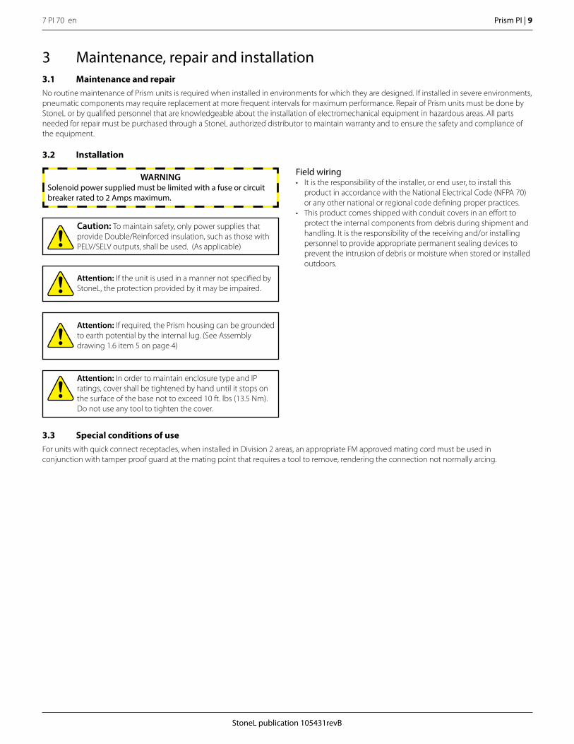
Attention: If required, the Prism housing can be grounded to earth potential by the internal lug. (See Assembly drawing 1.6 item 5 on page 4)
Attention: In order to maintain enclosure type and IP ratings, cover shall be tightened by hand until it stops on the surface of the base not to exceed 10 ft. lbs (13.5 Nm). Do not use any tool to tighten the cover.
Attention: If the unit is used in a manner not specified by StoneL, the protection provided by it may be impaired.
WARNINGSolenoid power supplied must be limited with a fuse or circuit breaker rated to 2 Amps maximum.
Field wiring• It is the responsibility of the installer, or end user, to install this
product in accordance with the National Electrical Code (NFPA 70) or any other national or regional code defining proper practices.
• This product comes shipped with conduit covers in an effort to protect the internal components from debris during shipment and handling. It is the responsibility of the receiving and/or installing personnel to provide appropriate permanent sealing devices to prevent the intrusion of debris or moisture when stored or installed outdoors.
Caution: To maintain safety, only power supplies that provide Double/Reinforced insulation, such as those with PELV/SELV outputs, shall be used. (As applicable)
3.3 Special conditions of useFor units with quick connect receptacles, when installed in Division 2 areas, an appropriate FM approved mating cord must be used in conjunction with tamper proof guard at the mating point that requires a tool to remove, rendering the connection not normally arcing.
7 PI 70 en10 | Prism PI
StoneL publication 105431revB
4 Function specific details4.1 Sensor/switching modules
4.1.1 SST NO sensor (33S)
Common receptacle options pin-out
Signal
OPEN NO
4-PIN MICRO CONNECTOR (M12)
CLOSED NO
CLOSED C
OPEN C
Pin
1
2
3
4MALE (PINS)
1 2
4 3
With solenoid
No solenoid
CLOSED C
MALE (PINS)
MALE (PINS)
1
1
2
2
5
5
4
4
3
3
5-PIN MICRO CONNECTOR (M12)
5-PIN MINI CONNECTOR
CLOSED NO
not used
OPEN NO
OPEN C
Pin
1
2
3
4
5
OPEN/CLOSED C
CLOSED NO
OPEN NO
SOL PWR 2
SOL PWR 1
Pin
1
2
3
4
5
Caution: A series load resistor must be used when bench testing in order to ensure proper module operation.
Caution: Performing this procedure will cause the sensor inputs to change states. Performing this procedure is not recommended during a live process.
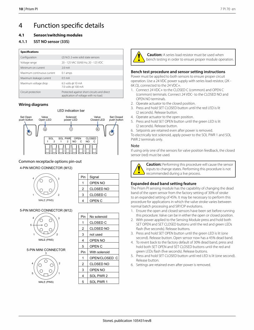
Bench test procedure and sensor setting instructionsPower must be applied to both sensors to ensure proper circuit operation. Use a 24 VDC power supply with series load resistor, (2K - 6K Ω), connected to the 24 VDC+.1. Connect 24 VDC+ to the CLOSED C (common) and OPEN C
(common) terminals. Connect 24 VDC- to the CLOSED NO and OPEN NO terminals.
2. Operate actuator to the closed position.3. Press and hold SET CLOSED button until the red LED is lit
(2 seconds). Release button.4. Operate actuator to the open position.5. Press and hold SET OPEN button until the green LED is lit
(2 seconds). Release button.6. Setpoints are retained even after power is removed.To electrically test solenoid, apply power to the SOL PWR 1 and SOL PWR 2 terminals only.
NoteIf using only one of the sensors for valve position feedback, the closed sensor (red) must be used.
Expanded dead band setting featureThe Prism PI sensing module has the capability of changing the dead band of the open sensor from the factory setting of 30% of stroke to an expanded setting of 45%. It may be necessary to perform this procedure for applications in which the valve stroke varies between normal batch processing and SIP/CIP evolutions. 1. Ensure the open and closed sensors have been set before running
this procedure. Valve can be in either the open or closed position.2. With power applied to the Sensing Module press and hold both
SET OPEN and SET CLOSED buttons until the red and green LEDs flash (five seconds). Release buttons.
3. Press and hold SET OPEN button until the green LED is lit (one second). Release button. Open sensor now has a 45% dead band.
4. To revert back to the factory default of 30% dead band, press and hold both SET OPEN and SET CLOSED buttons until the red and green LEDs flash (five seconds). Release buttons.
5. Press and hold SET CLOSED button until red LED is lit (one second). Release button.
6. Settings are retained even after power is removed.
Wiring diagrams
Set Openpush button
Set Closedpush button
Valve Open LED
Solenoidpower LED
YG
Valve Closed LED
R
LED indication bar
PWR2
1
SOL OPEN CLOSEDSOL1
NO
C CNO
2
Specifications
Configuration (2) N.O. 2-wire solid state sensors
Voltage range 20 - 125 VAC 50/60 Hz; 20 - 125 VDC
Minimum on current 2.0 mA
Maximum continuous current 0.1 amps
Maximum leakage current 0.5 mA
Maximum voltage drop 6.5 volts @ 10 mA7.0 volts @ 100 mA
Circuit protection Protected against short circuits and direct application of voltage with no load.
StoneL publication 105431revB
7 PI 70 en Prism PI | 11
4.1 Sensor/switching modules
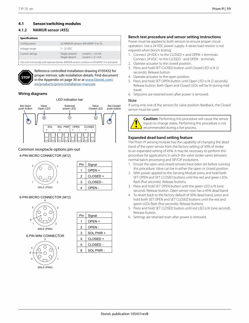
4.1.2 NAMUR sensor (45S)
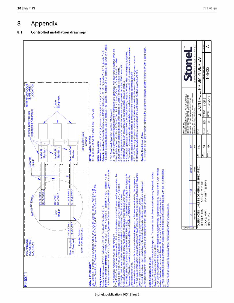
Reference controlled installation drawing #105432 for proper intrinsic safe installation details. Find document in the Appendix on page 30 or at www.StoneL.com/en/products/prism/installation-manuals
STOP
Expanded dead band setting featureThe Prism PI sensing module has the capability of changing the dead band of the open sensor from the factory setting of 30% of stroke to an expanded setting of 45%. It may be necessary to perform this procedure for applications in which the valve stroke varies between normal batch processing and SIP/CIP evolutions. 1. Ensure the open and closed sensors have been set before running
this procedure. Valve can be in either the open or closed position.2. With power applied to the Sensing Module press and hold both
SET OPEN and SET CLOSED buttons until the red and green LEDs flash (five seconds). Release buttons.
3. Press and hold SET OPEN button until the green LED is lit (one second). Release button. Open sensor now has a 45% dead band.
4. To revert back to the factory default of 30% dead band, press and hold both SET OPEN and SET CLOSED buttons until the red and green LEDs flash (five seconds). Release buttons.
5. Press and hold SET CLOSED button until red LED is lit (one second). Release button.
6. Settings are retained even after power is removed.
Caution: Performing this procedure will cause the sensor inputs to change states. Performing this procedure is not recommended during a live process.
Wiring diagrams
Set Openpush button
Set Closedpush button
LED indication bar
PWR-
+
SOL OPEN CLOSEDSOL+
+
- -+
-
Valve Open LED
Solenoidpower LED
YR
Valve Closed LED
G
Signal
OPEN +
MALE (PINS)
MALE (PINS)
1
1
2
2
5
6
4
5
3
4
3
6-PIN MICRO CONNECTOR (M12)
6-PIN MINI CONNECTOR
OPEN -
SOL PWR +
CLOSED +
CLOSED -
Pin
1
2
3
4
5
SOL PWR -6
6
Common receptacle options pin-out
Signal
OPEN +
4-PIN MICRO CONNECTOR (M12)
CLOSED +
CLOSED -
OPEN -
Pin
1
2
3
4MALE (PINS)
1 2
4 3
Specifications
Configuration (2) NAMUR sensors (EN 60947-5-6; IS)
Voltage range 5 - 25 VDC
Current ratings Target presentTarget absent
current < 1.0 mA current > 2.1 mA
Use with intrinsically safe repeater barrier. NAMUR sensors conform to EN 60947-5-6 standard.
Bench test procedure and sensor setting instructionsPower must be applied to both sensors to ensure proper circuit operation. Use a 24 VDC power supply. A series load resistor is not required when bench testing. 1. Connect 24 VDC+ to the CLOSED + and OPEN + terminals.
Connect 24 VDC- to the CLOSED - and OPEN - terminals.2. Operate actuator to the closed position. 3. Press and hold SET CLOSED button until Closed LED is lit (2
seconds). Release button.4. Operate actuator to the open position.5. Press and hold SET OPEN button until Open LED is lit (2 seconds).
Release button. Both Open and Closed LEDs will be lit during mid-travel.
6. Setpoints are retained even after power is removed.
NoteIf using only one of the sensors for valve position feedback, the Closed sensor must be used.

7 PI 70 en12 | Prism PI
StoneL publication 105431revB
Typical basic intrinsically safe circuits
NAMUR sensor circuit
Solenoid circuit
4.1.2 NAMUR sensor (45S) continued
** Barrier off state (target off): current in NAMUR sensor circuit >2.1 mABarrier on state (target on): current in NAMUR sensor circuit <1.0 mA
powersource
Hazardous area
NAMURrepeaterbarrier
24 VDC
computer input
8 VDC
I = 0.5mA to 5.0mA**
NAMUR sensor
powersource
Hazardous area
solenoidbarrier
24 VDC
computer output
solenoid coil
StoneL publication 105431revB
7 PI 70 en Prism PI | 13
4.1 Sensor/switching modules
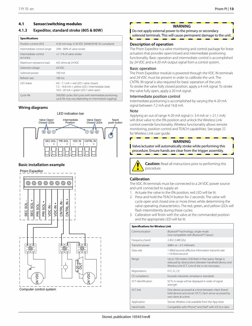
4.1.3 Expeditor, standard stroke (80S & 80W)
Specifications
Position control (AO) 4-20 mA loop, 9-30 VDC (NAMUR NE 43 compliant)
Intermediate control range 20% - 80% of valve stroke
Intermediate control accuracy
+/- 3 % of valve stroke
Maximum resistance load 425 ohms @ 24 VDC
Solenoid voltage 24 VDC
Solenoid power 100 mA
Refresh rate 100 ms
LED states 4.0 - 7.1 mA = red LED / valve closed7.2 - 16.8 mA = yellow LED / intermediate state16.9 - 20 mA = green LED / valve open
Cycle life 500,000 cycles (full cycles with intermediate positioning, cycle life may vary depending on intermediate toggling)
Wiring diagrams
Basic installation example
Teachpush button
Valve Open/Closed LEDs
IntermediatePosition
Y YG G
Valve Open/ Closed LEDs
RR
LED indication bar
+ -
SEC SOL PRI SOL VDC IN CNTRL IN-
-
+ +-
+
Description of operationThe Prism Expeditor is a valve monitoring and control package for linear actuators that provides open/closed and intermediate positioning functionality. Basic operation and intermediate control is accomplished by 24 VDC and a 4-20 mA output signal from a control system.
Basic operationThe Prism Expeditor module is powered through the VDC IN terminals and 24 VDC must be present in order to calibrate the unit. The CNTRL IN signal is also required for basic operation of the unit.To stroke the valve fully closed position, apply a 4 mA signal. To stroke the valve fully open, apply a 20 mA signal.
Intermediate position controlIntermediate positioning is accomplished by varying the 4-20 mA signal between 7.2 mA and 16.8 mA.
NoteApplying an out of range 4-20 mA signal (< 3.4 mA or > 21.1 mA) will drive valve to the 0% position and unlock the Wireless Link control override functionality. Wireless functionality allows remote monitoring, position control and TEACH capabilities. See page 22 for Wireless Link user guide.
WARNINGDo not apply external power to the primary or secondary solenoid terminals. This will cause permanent damage to the unit.
CalibrationThe VDC IN terminals must be connected to a 24 VDC power source and unit connected to supply air. 1. Actuate the valve to the 0% position, red LED will be lit.2. Press and hold the TEACH button for 2 seconds. The valve will
cycle open and closed one or more times while determining the valve operating characteristics. The red, green, and yellow LEDs will flash intermittently during these cycles.
3. Calibration will finish with the valve at the commanded position and the appropriate LED will be lit.
24 V
DC
4-20
mA
OU
T
24 V
DC
Prism Expeditor
Computer control system
PR
I SO
L -
PR
I SO
L +
VD
C IN
-
VD
C IN
+
CN
TRL
IN -
CN
TRL
IN +
SE
C S
OL
-
SE
C S
OL
+
Caution: Read all instructions prior to performing this procedure.
WARNINGValve/actuator will automatically stroke while performing this procedure. Ensure hands are clear from the trigger assembly.
Specifications for Wireless Link
Communication Bluetooth® technology; single mode (not compatible with Bluetooth® Classic)
Frequency band 2.402-2.480 Ghz
Transmit power 4dBm or ~2.5 milliwatts
Data rate 1 Mbit/second; effective information transmit rate~10 Kbits/second
Range Up to 100 meters (330 feet) in free space. Range is reduced by obstructions between handheld device and Wireless Link VCT. Line of site is not necessary.
Registrations FCC, IC, CE
CE compliance Exceeds industrial compliance standards
VCT identification VCTs in range will be displayed in order of signal strength
VCT link One device accessed at a time between client (hand-held device) and server (VCT). Each server accessed by one client at a time
Application StoneL Wireless Link available from the App store
Hand-helds Compatible with iPhone® and iPad® with iOS 8 or later
7 PI 70 en14 | Prism PI
StoneL publication 105431revB
Y YG G RR
LED indication bar
Valve Open/Closed LEDs
IntermediatePosition
Valve Open/ Closed LEDs
-
POS FB +
-
CNTRL IN +
-VDC IN
+ -OPEN
+ -
CLOSED +
Trainpush button
+ -SE
C S
OL
PR
I SO
L-
+
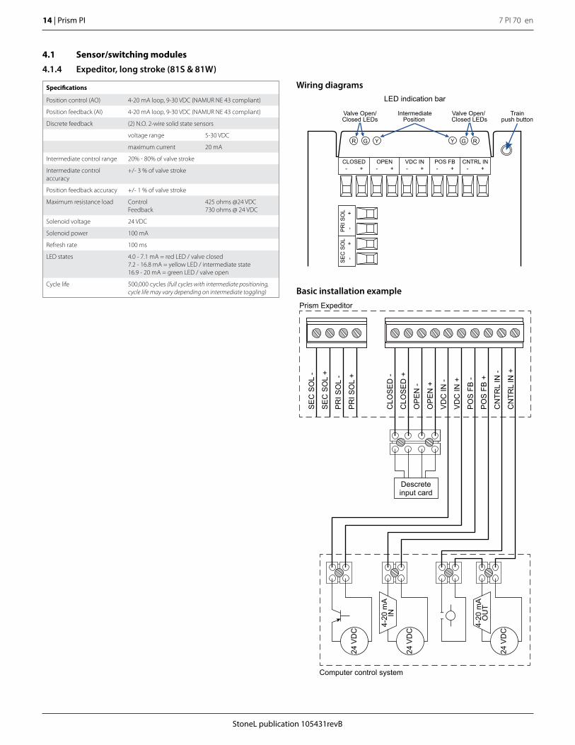
4.1 Sensor/switching modules
4.1.4 Expeditor, long stroke (81S & 81W)
Wiring diagramsSpecifications
Position control (AO) 4-20 mA loop, 9-30 VDC (NAMUR NE 43 compliant)
Position feedback (AI) 4-20 mA loop, 9-30 VDC (NAMUR NE 43 compliant)
Discrete feedback (2) N.O. 2-wire solid state sensors
voltage range 5-30 VDC
maximum current 20 mA
Intermediate control range 20% - 80% of valve stroke
Intermediate control accuracy
+/- 3 % of valve stroke
Position feedback accuracy +/- 1 % of valve stroke
Maximum resistance load Control Feedback
425 ohms @24 VDC730 ohms @ 24 VDC
Solenoid voltage 24 VDC
Solenoid power 100 mA
Refresh rate 100 ms
LED states 4.0 - 7.1 mA = red LED / valve closed7.2 - 16.8 mA = yellow LED / intermediate state16.9 - 20 mA = green LED / valve open
Cycle life 500,000 cycles (full cycles with intermediate positioning, cycle life may vary depending on intermediate toggling) Basic installation example
Prism Expeditor
4-20
mA
IN
24 V
DC
24 V
DC
4-20
mA
OU
T
24 V
DC
Computer control system
OP
EN
-
OP
EN
+
VD
C IN
-
VD
C IN
+
PO
S F
B -
PO
S F
B +
CN
TRL
IN -
CLO
SE
D -
CLO
SE
D +
PR
I SO
L -
PR
I SO
L +
SE
C S
OL
-
SE
C S
OL
+
CN
TRL
IN +
Descreteinput card
StoneL publication 105431revB
7 PI 70 en Prism PI | 15
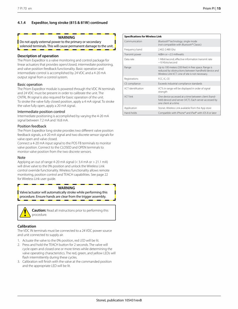
4.1.4 Expeditor, long stroke (81S & 81W) continued
Description of operationThe Prism Expeditor is a valve monitoring and control package for linear actuators that provides open/closed, intermediate positioning, and valve position feedback functionality. Basic operation and intermediate control is accomplished by 24 VDC and a 4-20 mA output signal from a control system.
Basic operationThe Prism Expeditor module is powered through the VDC IN terminals and 24 VDC must be present in order to calibrate the unit. The CNTRL IN signal is also required for basic operation of the unit.To stroke the valve fully closed position, apply a 4 mA signal. To stroke the valve fully open, apply a 20 mA signal.
Intermediate position controlIntermediate positioning is accomplished by varying the 4-20 mA signal between 7.2 mA and 16.8 mA.
Position feedbackThe Prism Expeditor long stroke provides two different valve position feedback signals, a 4-20 mA signal and two discrete sensor signals for valve open and valve closed.Connect a 4-20 mA input signal to the POS FB terminals to monitor valve position. Connect to the CLOSED and OPEN terminals to monitor valve position from the two discrete sensors.
NoteApplying an out of range 4-20 mA signal (< 3.4 mA or > 21.1 mA) will drive valve to the 0% position and unlock the Wireless Link control override functionality. Wireless functionality allows remote monitoring, position control and TEACH capabilities. See page 22 for Wireless Link user guide.
WARNINGDo not apply external power to the primary or secondary solenoid terminals. This will cause permanent damage to the unit.
CalibrationThe VDC IN terminals must be connected to a 24 VDC power source and unit connected to supply air.
1. Actuate the valve to the 0% position, red LED will be lit.2. Press and hold the TEACH button for 2 seconds. The valve will
cycle open and closed one or more times while determining the valve operating characteristics. The red, green, and yellow LEDs will flash intermittently during these cycles.
3. Calibration will finish with the valve at the commanded position and the appropriate LED will be lit.
Caution: Read all instructions prior to performing this procedure.
WARNINGValve/actuator will automatically stroke while performing this procedure. Ensure hands are clear from the trigger assembly.
Specifications for Wireless Link
Communication Bluetooth® technology; single mode (not compatible with Bluetooth® Classic)
Frequency band 2.402-2.480 Ghz
Transmit power 4dBm or ~2.5 milliwatts
Data rate 1 Mbit/second; effective information transmit rate~10 Kbits/second
Range Up to 100 meters (330 feet) in free space. Range is reduced by obstructions between handheld device and Wireless Link VCT. Line of site is not necessary.
Registrations FCC, IC, CE
CE compliance Exceeds industrial compliance standards
VCT identification VCTs in range will be displayed in order of signal strength
VCT link One device accessed at a time between client (hand-held device) and server (VCT). Each server accessed by one client at a time
Application StoneL Wireless Link available from the App store
Hand-helds Compatible with iPhone® and iPad® with iOS 8 or later
7 PI 70 en16 | Prism PI
StoneL publication 105431revB
4.2 Valve communication terminals (VCT)
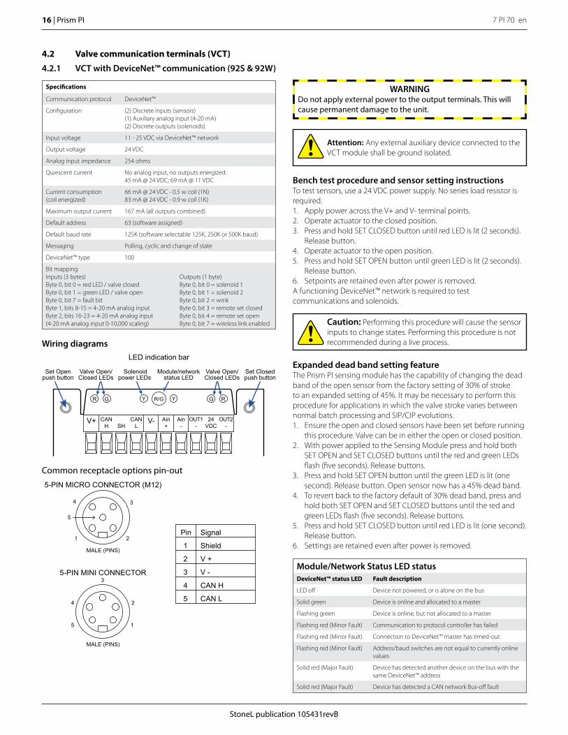
4.2.1 VCT with DeviceNet™ communication (92S & 92W)
Expanded dead band setting featureThe Prism PI sensing module has the capability of changing the dead band of the open sensor from the factory setting of 30% of stroke to an expanded setting of 45%. It may be necessary to perform this procedure for applications in which the valve stroke varies between normal batch processing and SIP/CIP evolutions. 1. Ensure the open and closed sensors have been set before running
this procedure. Valve can be in either the open or closed position.2. With power applied to the Sensing Module press and hold both
SET OPEN and SET CLOSED buttons until the red and green LEDs flash (five seconds). Release buttons.
3. Press and hold SET OPEN button until the green LED is lit (one second). Release button. Open sensor now has a 45% dead band.
4. To revert back to the factory default of 30% dead band, press and hold both SET OPEN and SET CLOSED buttons until the red and green LEDs flash (five seconds). Release buttons.
5. Press and hold SET CLOSED button until red LED is lit (one second). Release button.
6. Settings are retained even after power is removed.
Caution: Performing this procedure will cause the sensor inputs to change states. Performing this procedure is not recommended during a live process.
Attention: Any external auxiliary device connected to the VCT module shall be ground isolated.
Wiring diagrams
V+ V-CANH
CANL
Ain+
Ain-
OUT1-
OUT2-
24VDC
SH
Set Openpush button
Set Closedpush button
Valve Open/Closed LEDs
Solenoidpower LEDs
Module/networkstatus LED
R/GY YR G
Valve Open/Closed LEDs
G R
LED indication bar
Specifications
Communication protocol DeviceNet™
Configuration (2) Discrete inputs (sensors)(1) Auxiliary analog input (4-20 mA)(2) Discrete outputs (solenoids)
Input voltage 11 - 25 VDC via DeviceNet™ network
Output voltage 24 VDC
Analog input impedance 254 ohms
Quiescent current No analog input, no outputs energized: 45 mA @ 24 VDC; 69 mA @ 11 VDC
Current consumption (coil energized)
66 mA @ 24 VDC - 0.5 w coil (1N)83 mA @ 24 VDC - 0.9 w coil (1K)
Maximum output current 167 mA (all outputs combined)
Default address 63 (software assigned)
Default baud rate 125K (software selectable 125K, 250K or 500K baud)
Messaging Polling, cyclic and change of state
DeviceNet™ type 100
Bit mappingInputs (3 bytes)Byte 0, bit 0 = red LED / valve closedByte 0, bit 1 = green LED / valve openByte 0, bit 7 = fault bitByte 1, bits 8-15 = 4-20 mA analog inputByte 2, bits 16-23 = 4-20 mA analog input(4-20 mA analog input 0-10,000 scaling)
Outputs (1 byte)Byte 0, bit 0 = solenoid 1Byte 0, bit 1 = solenoid 2Byte 0, bit 2 = winkByte 0, bit 3 = remote set closedByte 0, bit 4 = remote set openByte 0, bit 7 = wireless link enabled
Bench test procedure and sensor setting instructionsTo test sensors, use a 24 VDC power supply. No series load resistor is required.1. Apply power across the V+ and V- terminal points. 2. Operate actuator to the closed position.3. Press and hold SET CLOSED button until red LED is lit (2 seconds).
Release button. 4. Operate actuator to the open position.5. Press and hold SET OPEN button until green LED is lit (2 seconds).
Release button. 6. Setpoints are retained even after power is removed. A functioning DeviceNet™ network is required to test communications and solenoids.
WARNINGDo not apply external power to the output terminals. This will cause permanent damage to the unit.
Module/Network Status LED statusDeviceNet™ status LED Fault description
LED off Device not powered, or is alone on the bus
Solid green Device is online and allocated to a master
Flashing green Device is online, but not allocated to a master
Flashing red (Minor Fault) Communication to protocol controller has failed
Flashing red (Minor Fault) Connection to DeviceNet™ master has timed-out
Flashing red (Minor Fault) Address/baud switches are not equal to currently online values
Solid red (Major Fault) Device has detected another device on the bus with the same DeviceNet™ address
Solid red (Major Fault) Device has detected a CAN network Bus-off fault
Common receptacle options pin-out
Signal
ShieldMALE (PINS)
MALE (PINS)
1
1
2
2
5
5
4
4
3
3
5-PIN MICRO CONNECTOR (M12)
5-PIN MINI CONNECTOR
V +
V -
CAN H
CAN L
Pin
1
2
3
4
5
StoneL publication 105431revB
7 PI 70 en Prism PI | 17
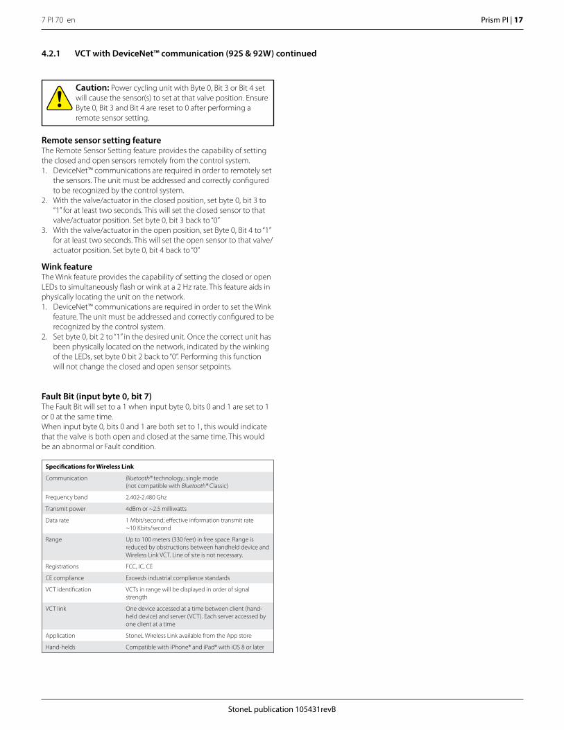
4.2.1 VCT with DeviceNet™ communication (92S & 92W) continued
Caution: Power cycling unit with Byte 0, Bit 3 or Bit 4 set will cause the sensor(s) to set at that valve position. Ensure Byte 0, Bit 3 and Bit 4 are reset to 0 after performing a remote sensor setting.
Remote sensor setting feature The Remote Sensor Setting feature provides the capability of setting the closed and open sensors remotely from the control system.1. DeviceNet™ communications are required in order to remotely set
the sensors. The unit must be addressed and correctly configured to be recognized by the control system.
2. With the valve/actuator in the closed position, set byte 0, bit 3 to “1” for at least two seconds. This will set the closed sensor to that valve/actuator position. Set byte 0, bit 3 back to “0”
3. With the valve/actuator in the open position, set Byte 0, Bit 4 to “1” for at least two seconds. This will set the open sensor to that valve/actuator position. Set byte 0, bit 4 back to “0”
Wink feature The Wink feature provides the capability of setting the closed or open LEDs to simultaneously flash or wink at a 2 Hz rate. This feature aids in physically locating the unit on the network. 1. DeviceNet™ communications are required in order to set the Wink
feature. The unit must be addressed and correctly configured to be recognized by the control system.
2. Set byte 0, bit 2 to “1” in the desired unit. Once the correct unit has been physically located on the network, indicated by the winking of the LEDs, set byte 0 bit 2 back to “0”. Performing this function will not change the closed and open sensor setpoints.
Fault Bit (input byte 0, bit 7)The Fault Bit will set to a 1 when input byte 0, bits 0 and 1 are set to 1 or 0 at the same time.When input byte 0, bits 0 and 1 are both set to 1, this would indicate that the valve is both open and closed at the same time. This would be an abnormal or Fault condition.
Specifications for Wireless Link
Communication Bluetooth® technology; single mode (not compatible with Bluetooth® Classic)
Frequency band 2.402-2.480 Ghz
Transmit power 4dBm or ~2.5 milliwatts
Data rate 1 Mbit/second; effective information transmit rate~10 Kbits/second
Range Up to 100 meters (330 feet) in free space. Range is reduced by obstructions between handheld device and Wireless Link VCT. Line of site is not necessary.
Registrations FCC, IC, CE
CE compliance Exceeds industrial compliance standards
VCT identification VCTs in range will be displayed in order of signal strength
VCT link One device accessed at a time between client (hand-held device) and server (VCT). Each server accessed by one client at a time
Application StoneL Wireless Link available from the App store
Hand-helds Compatible with iPhone® and iPad® with iOS 8 or later
7 PI 70 en18 | Prism PI
StoneL publication 105431revB
4.2 Valve communication terminals (VCT)
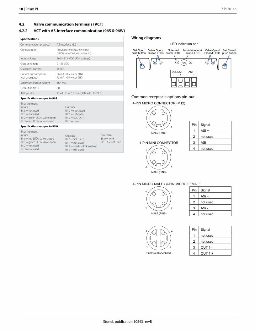
4.2.2 VCT with AS-Interface communication (96S & 96W)
Specifications
Communication protocol AS-Interface v3.0
Configuration (2) Discrete Inputs (sensors)(1) Discrete Output (solenoid)
Input voltage 26.5 - 31.6 VDC (AS-I voltage)
Output voltage 21-26 VDC
Quiescent current 35 mA
Current consumption (coil energized)
56 mA - 0.5 w coil (1N)73 mA - 0.9 w coil (1K)
Maximum output current 167 mA
Default address 00
ID/IO codes ID = F; IO = 7; ID1 = F; ID2 = E (S-7.F.E.)
Specifications unique to 96S
Bit assignmentInputsBit 0 = not usedBit 1 = not usedBit 2 = green LED / valve openBit 3 = red LED / valve closed
OutputsBit 0 = set closedBit 1 = set openBit 2 = SOL OUTBit 3 = wink
Specifications unique to 96W
Bit assignmentInputsBit 0 = red LED / valve closedBit 1 = green LED / valve openBit 2 = not usedBit 3 = not used
OutputsBit 0 = SOL OUTBit 1 = not usedBit 2 = wireless link enabledBit 3 = not used
ParameterBit 0 = winkBit 1-3 = not used
Common receptacle options pin-out
Wiring diagrams
SOL OUT -
+
ASI -
+
Set Openpush button
Set Closedpush button
Valve Open/Closed LEDs
Solenoidpower LEDs
Module/networkstatus LED
R/GY YR G
Valve Open/Closed LEDs
G R
LED indication bar
Signal
ASi +MALE (PINS)
1 2
4 3
MALE (PINS)
2 4
1 3
4-PIN MICRO CONNECTOR (M12)
4-PIN MINI CONNECTOR
not used
ASi -
not used
Pin
1
2
3
4
4-PIN MICRO MALE / 4-PIN MICRO FEMALE
Signal
ASi +
MALE (PINS)
1 2
4 3
not used
ASi -
not used
Pin
1
2
3
4
Signal
not used
not used
OUT 1 -
OUT 1 +
Pin
1
2
3
4FEMALE (SOCKETS)
2 1
3 4
StoneL publication 105431revB
7 PI 70 en Prism PI | 19
Bench test procedure and sensor setting instructionsTo test sensors, use a 24 VDC power supply. No series load resistor is required. 1. Apply power across the ASi+ and ASi- terminal points.2. Operate actuator to the CLOSED position. 3. Press and hold SET CLOSED button until red LED is lit (2 seconds).
Release button.4. Operate actuator to the OPEN position.5. Press and hold SET OPEN button until green LED is lit (2 seconds).
Release button.6. Setpoints are retained even after power is removed. A functioning AS-Interface network is required to test communications and solenoid.
WARNINGDo not apply external power to the output terminals. This will cause permanent damage to the unit.
Remote sensor setting feature (96S only)This feature provides the capability of setting the Closed and Open sensors remotely from the Control System or from the AS-Interface Gateway/Master.1. AS-Interface communications are required in order to remotely set
the sensors. The unit must be addressed and correctly configured to be recognized by the Control System or the AS-Interface Gateway/Master.
2. With the valve/actuator in the closed position, set Output Bit 1 (DO 0) to “1” for at least two seconds. This will set the Closed sensor to that valve/actuator position. Set Output Bit 1 (DO 0) back to “0”
3. With the valve/actuator in the open position, set Output Bit 2 (DO 1) to “1” for at least two seconds. This will set the Open sensor to that valve/actuator position. Set Output Bit 2 (DO 1) back to “0”
4.2.2 VCT with AS-Interface communication (96S & 96W) continued
AS-Interface Wink feature This feature provides the capability of setting the CLOSED and OPEN LEDs to simultaneously flash or “wink”. This feature aids in physically locating the unit on the network.
1. AS-Interface communications are required in order to set the “Wink” feature. The unit must be addressed and correctly configured to be recognized by the Control System or the AS-Interface Gateway/Master.
2. Wink feature bit settings differ for 96S and 96W.a. For 96S units, set Output Bit 4 (DO3) to “1” in the desired
unit. Once the correct unit has been physically located on the network, indicated by the “winking” of the CLOSED and OPEN LEDs, set Output Bit 4 (DO3) back to “0”. Performing this function will not change the Closed and Open sensor setpoints.
b. For 96W units, set parameter Bit 0 to “1” in the desired unit. Once the correct unit has been physically located on the network, indicated by the “winking” of the CLOSED and OPEN LEDs, set parameter Bit 0 back to “0”. Performing this function will not change the Closed and Open sensor setpoints.
Expanded dead band setting featureThe Prism PI sensing module has the capability of changing the dead band of the open sensor from the factory setting of 30% of stroke to an expanded setting of 45%. It may be necessary to perform this procedure for applications in which the valve stroke varies between normal batch processing and SIP/CIP evolutions. 1. Ensure the open and closed sensors have been set before running
this procedure. Valve can be in either the open or closed position.2. With power applied to the Sensing Module press and hold both
SET OPEN and SET CLOSED buttons until the red and green LEDs flash (five seconds). Release buttons.
3. Press and hold SET OPEN button until the green LED is lit (one second). Release button. Open sensor now has a 45% dead band.
4. To revert back to the factory default of 30% dead band, press and hold both SET OPEN and SET CLOSED buttons until the red and green LEDs flash (five seconds). Release buttons.
5. Press and hold SET CLOSED button until red LED is lit (one second). Release button.
6. Settings are retained even after power is removed.
Caution: Performing this procedure will cause the sensor inputs to change states. Performing this procedure is not recommended during a live process.
Power/Fault LED statusAS-i status LED Fault description
LED off Device does not have power
Solid green Normal operation
Flashing red/green Output shorted
Flashing red/green No magnet detected
Flashing red/green Internal sensor fault - sensor may need replacing
Flashing yellow/red No data exchange (device address = 0)
Solid red No data exchange
Specifications for Wireless Link
Communication Bluetooth® technology; single mode (not compatible with Bluetooth® Classic)
Frequency band 2.402-2.480 Ghz
Transmit power 4dBm or ~2.5 milliwatts
Data rate 1 Mbit/second; effective information transmit rate~10 Kbits/second
Range Up to 100 meters (330 feet) in free space. Range is reduced by obstructions between handheld device and Wireless Link VCT. Line of site is not necessary.
Registrations FCC, IC, CE
CE compliance Exceeds industrial compliance standards
VCT identification VCTs in range will be displayed in order of signal strength
VCT link One device accessed at a time between client (hand-held device) and server (VCT). Each server accessed by one client at a time
Application StoneL Wireless Link available from the App store
Hand-helds Compatible with iPhone® and iPad® with iOS 8 or later
7 PI 70 en20 | Prism PI
StoneL publication 105431revB
4.2 Valve communication terminals (VCT)
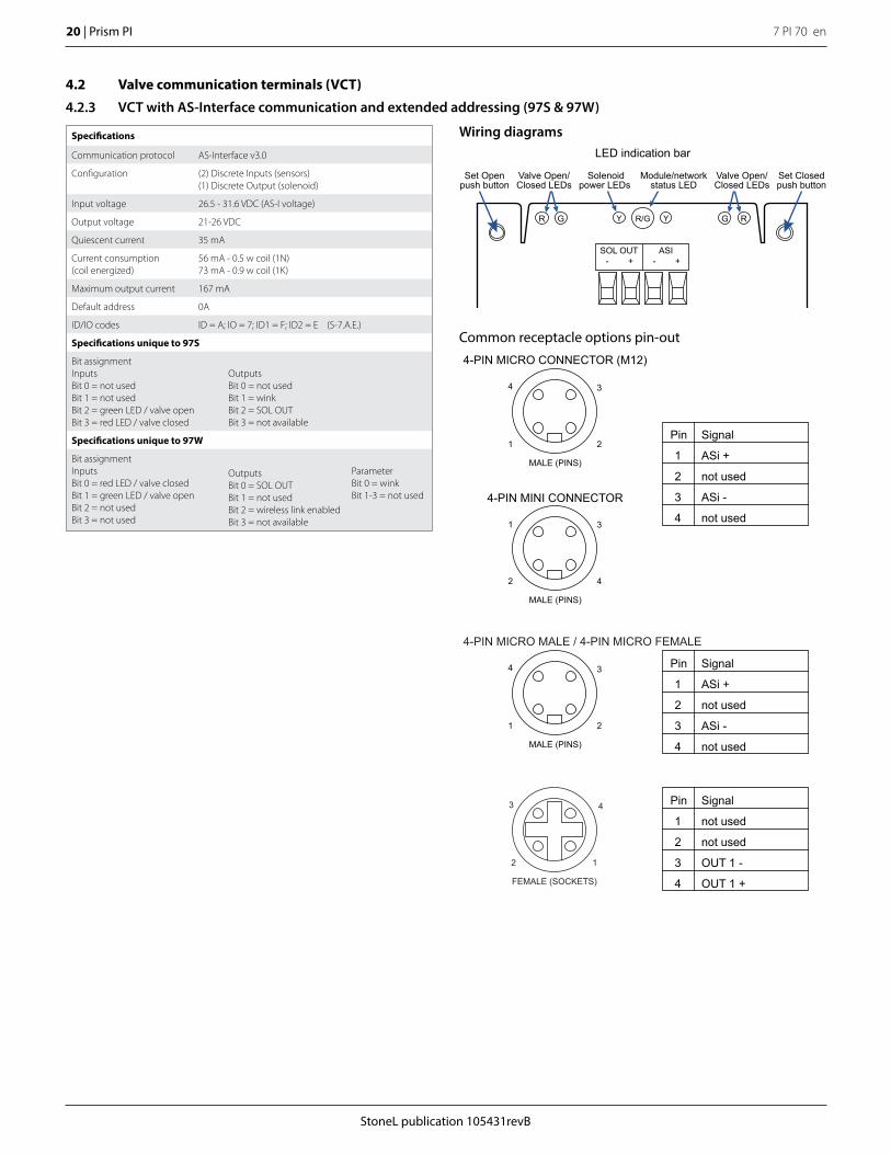
4.2.3 VCT with AS-Interface communication and extended addressing (97S & 97W)
Common receptacle options pin-out
Wiring diagrams
SOL OUT -
+
ASI -
+
Set Openpush button
Set Closedpush button
Valve Open/Closed LEDs
Solenoidpower LEDs
Module/networkstatus LED
R/GY YR G
Valve Open/Closed LEDs
G R
LED indication bar
Signal
ASi +MALE (PINS)
1 2
4 3
MALE (PINS)
2 4
1 3
4-PIN MICRO CONNECTOR (M12)
4-PIN MINI CONNECTOR
not used
ASi -
not used
Pin
1
2
3
4
4-PIN MICRO MALE / 4-PIN MICRO FEMALE
Signal
ASi +
MALE (PINS)
1 2
4 3
not used
ASi -
not used
Pin
1
2
3
4
Signal
not used
not used
OUT 1 -
OUT 1 +
Pin
1
2
3
4FEMALE (SOCKETS)
2 1
3 4
Specifications
Communication protocol AS-Interface v3.0
Configuration (2) Discrete Inputs (sensors)(1) Discrete Output (solenoid)
Input voltage 26.5 - 31.6 VDC (AS-I voltage)
Output voltage 21-26 VDC
Quiescent current 35 mA
Current consumption (coil energized)
56 mA - 0.5 w coil (1N)73 mA - 0.9 w coil (1K)
Maximum output current 167 mA
Default address 0A
ID/IO codes ID = A; IO = 7; ID1 = F; ID2 = E (S-7.A.E.)
Specifications unique to 97S
Bit assignmentInputsBit 0 = not usedBit 1 = not usedBit 2 = green LED / valve openBit 3 = red LED / valve closed
OutputsBit 0 = not usedBit 1 = winkBit 2 = SOL OUTBit 3 = not available
Specifications unique to 97W
Bit assignmentInputsBit 0 = red LED / valve closedBit 1 = green LED / valve openBit 2 = not usedBit 3 = not used
OutputsBit 0 = SOL OUTBit 1 = not usedBit 2 = wireless link enabledBit 3 = not available
ParameterBit 0 = winkBit 1-3 = not used
StoneL publication 105431revB
7 PI 70 en Prism PI | 21
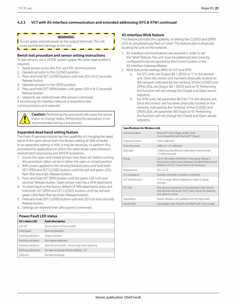
Bench test procedure and sensor setting instructionsTo test sensors, use a 24 VDC power supply. No series load resistor is required. 1. Apply power across the ASi+ and ASi- terminal points.2. Operate actuator to the CLOSED position. 3. Press and hold SET CLOSED button until red LED is lit (2 seconds).
Release button.4. Operate actuator to the OPEN position.5. Press and hold SET OPEN button until green LED is lit (2 seconds).
Release button.6. Setpoints are retained even after power is removed. A functioning AS-Interface network is required to test communications and solenoid.
WARNINGDo not apply external power to the output terminals. This will cause permanent damage to the unit.
4.2.3 VCT with AS-Interface communication and extended addressing (97S & 97W) continued
Expanded dead band setting featureThe Prism PI sensing module has the capability of changing the dead band of the open sensor from the factory setting of 30% of stroke to an expanded setting of 45%. It may be necessary to perform this procedure for applications in which the valve stroke varies between normal batch processing and SIP/CIP evolutions. 1. Ensure the open and closed sensors have been set before running
this procedure. Valve can be in either the open or closed position.2. With power applied to the Sensing Module press and hold both
SET OPEN and SET CLOSED buttons until the red and green LEDs flash (five seconds). Release buttons.
3. Press and hold SET OPEN button until the green LED is lit (one second). Release button. Open sensor now has a 45% dead band.
4. To revert back to the factory default of 30% dead band, press and hold both SET OPEN and SET CLOSED buttons until the red and green LEDs flash (five seconds). Release buttons.
5. Press and hold SET CLOSED button until red LED is lit (one second). Release button.
6. Settings are retained even after power is removed.
Caution: Performing this procedure will cause the sensor inputs to change states. Performing this procedure is not recommended during a live process.
Power/Fault LED statusAS-i status LED Fault description
LED off Device does not have power
Solid green Normal operation
Flashing red/green Output shorted
Flashing red/green No magnet detected
Flashing red/green Internal sensor fault - sensor may need replacing
Flashing yellow/red No data exchange (device address = 0)
Solid red No data exchange
AS-Interface Wink feature This feature provides the capability of setting the CLOSED and OPEN LEDs to simultaneously flash or “wink”. This feature aids in physically locating the unit on the network.
1. AS-Interface communications are required in order to set the “Wink” feature. The unit must be addressed and correctly configured to be recognized by the Control System or the AS-Interface Gateway/Master.
2. Wink feature bit settings differ for 97S and 97W.a. For 97S units, set Output Bit 1 (DO2) to “1” in the desired
unit. Once the correct unit has been physically located on the network, indicated by the “winking” of the CLOSED and OPEN LEDs, set Output Bit 1 (DO2) back to “0”. Performing this function will not change the Closed and Open sensor setpoints.
b. For 97W units, set parameter Bit 0 to “1” in the desired unit. Once the correct unit has been physically located on the network, indicated by the “winking” of the CLOSED and OPEN LEDs, set parameter Bit 0 back to “0”. Performing this function will not change the Closed and Open sensor setpoints.
Specifications for Wireless Link
Communication Bluetooth® technology; single mode (not compatible with Bluetooth® Classic)
Frequency band 2.402-2.480 Ghz
Transmit power 4dBm or ~2.5 milliwatts
Data rate 1 Mbit/second; effective information transmit rate~10 Kbits/second
Range Up to 100 meters (330 feet) in free space. Range is reduced by obstructions between handheld device and Wireless Link VCT. Line of site is not necessary.
Registrations FCC, IC, CE
CE compliance Exceeds industrial compliance standards
VCT identification VCTs in range will be displayed in order of signal strength
VCT link One device accessed at a time between client (hand-held device) and server (VCT). Each server accessed by one client at a time
Application StoneL Wireless Link available from the App store
Hand-helds Compatible with iPhone® and iPad® with iOS 8 or later
7 PI 70 en22 | Prism PI
StoneL publication 105431revB
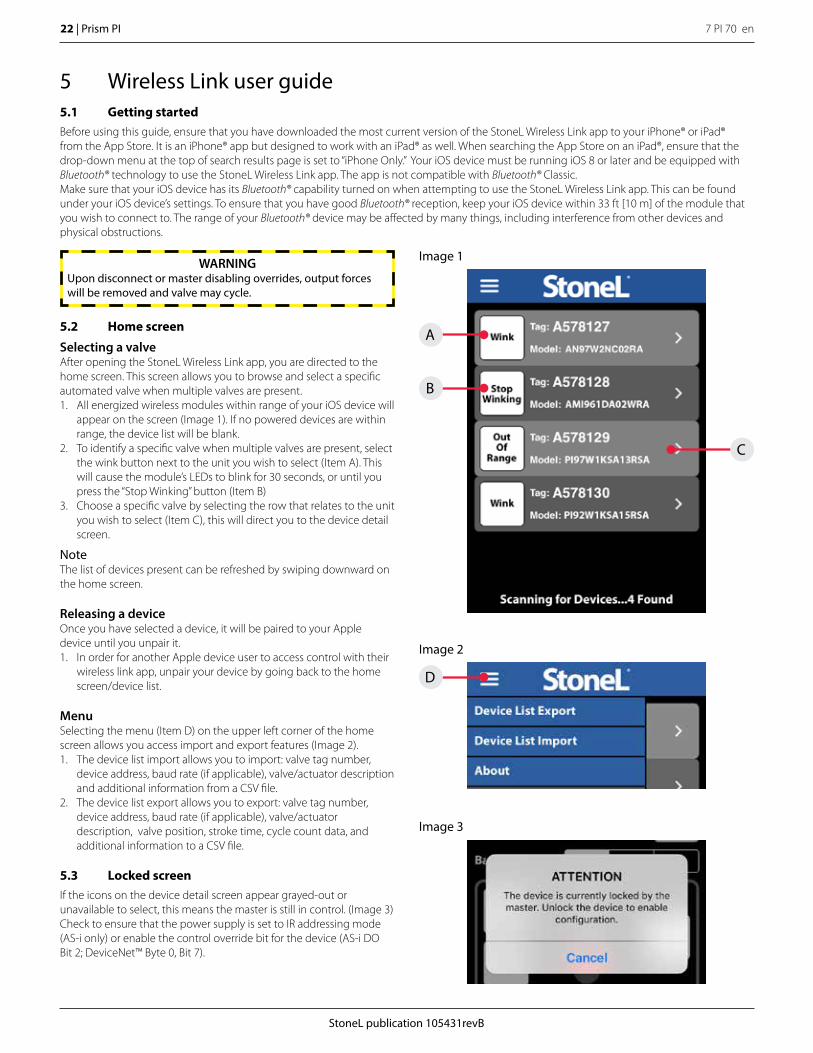
5.2 Home screen
Selecting a valveAfter opening the StoneL Wireless Link app, you are directed to the home screen. This screen allows you to browse and select a specific automated valve when multiple valves are present.1. All energized wireless modules within range of your iOS device will
appear on the screen (Image 1). If no powered devices are within range, the device list will be blank.
2. To identify a specific valve when multiple valves are present, select the wink button next to the unit you wish to select (Item A). This will cause the module’s LEDs to blink for 30 seconds, or until you press the “Stop Winking” button (Item B)
3. Choose a specific valve by selecting the row that relates to the unit you wish to select (Item C), this will direct you to the device detail screen.
NoteThe list of devices present can be refreshed by swiping downward on the home screen.
Releasing a deviceOnce you have selected a device, it will be paired to your Apple device until you unpair it. 1. In order for another Apple device user to access control with their
wireless link app, unpair your device by going back to the home screen/device list.
MenuSelecting the menu (Item D) on the upper left corner of the home screen allows you access import and export features (Image 2).1. The device list import allows you to import: valve tag number,
device address, baud rate (if applicable), valve/actuator description and additional information from a CSV file.
2. The device list export allows you to export: valve tag number, device address, baud rate (if applicable), valve/actuator description, valve position, stroke time, cycle count data, and additional information to a CSV file.
5.3 Locked screenIf the icons on the device detail screen appear grayed-out or unavailable to select, this means the master is still in control. (Image 3) Check to ensure that the power supply is set to IR addressing mode (AS-i only) or enable the control override bit for the device (AS-i DO Bit 2; DeviceNet™ Byte 0, Bit 7).
WARNINGUpon disconnect or master disabling overrides, output forces will be removed and valve may cycle.
Image 3
Image 2
Image 1
D
B
A
C
5 Wireless Link user guide5.1 Getting startedBefore using this guide, ensure that you have downloaded the most current version of the StoneL Wireless Link app to your iPhone® or iPad® from the App Store. It is an iPhone® app but designed to work with an iPad® as well. When searching the App Store on an iPad®, ensure that the drop-down menu at the top of search results page is set to “iPhone Only.” Your iOS device must be running iOS 8 or later and be equipped with Bluetooth® technology to use the StoneL Wireless Link app. The app is not compatible with Bluetooth® Classic.Make sure that your iOS device has its Bluetooth® capability turned on when attempting to use the StoneL Wireless Link app. This can be found under your iOS device’s settings. To ensure that you have good Bluetooth® reception, keep your iOS device within 33 ft [10 m] of the module that you wish to connect to. The range of your Bluetooth® device may be affected by many things, including interference from other devices and physical obstructions.
StoneL publication 105431revB
7 PI 70 en Prism PI | 23
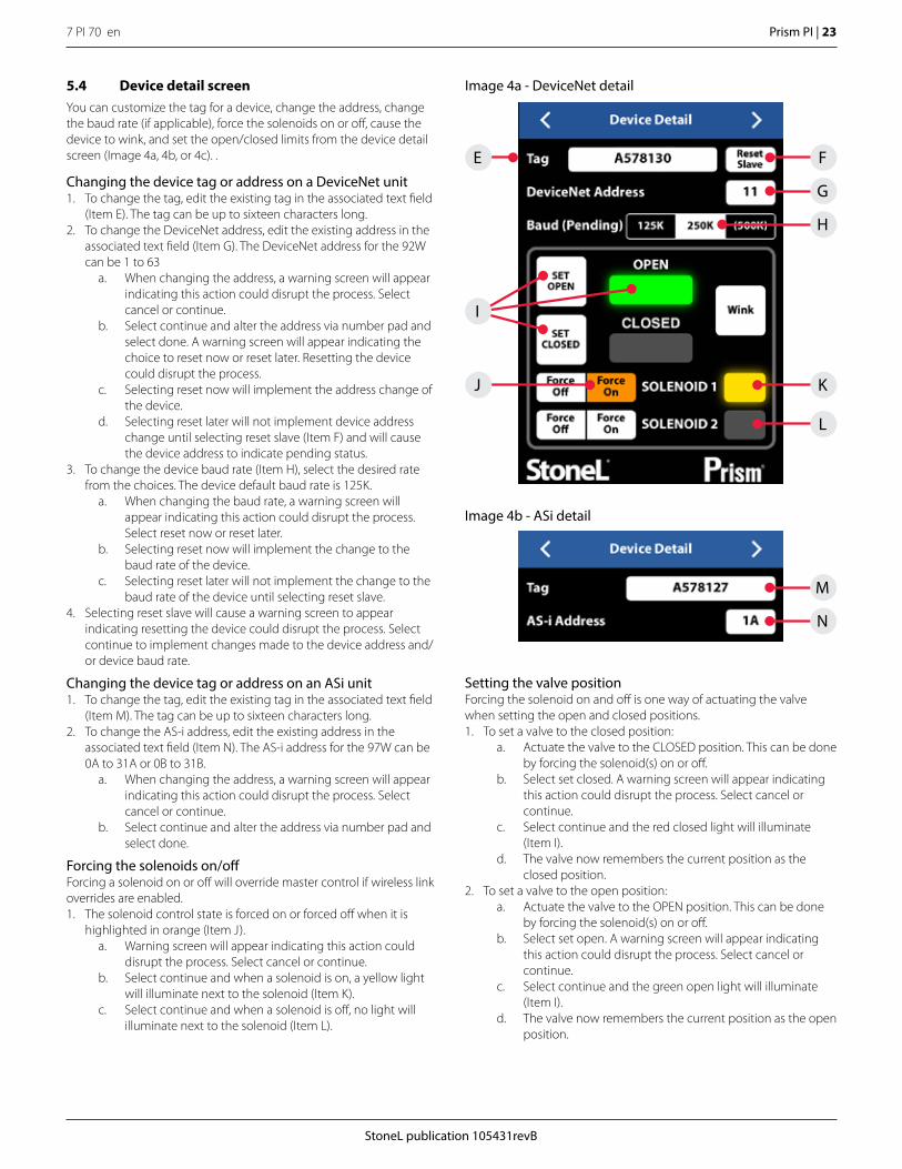
5.4 Device detail screenYou can customize the tag for a device, change the address, change the baud rate (if applicable), force the solenoids on or off, cause the device to wink, and set the open/closed limits from the device detail screen (Image 4a, 4b, or 4c). .
Image 4a - DeviceNet detail
Image 4b - ASi detail
E
M
K
L
J
I
G
F
N
H
Changing the device tag or address on a DeviceNet unit1. To change the tag, edit the existing tag in the associated text field
(Item E). The tag can be up to sixteen characters long.2. To change the DeviceNet address, edit the existing address in the
associated text field (Item G). The DeviceNet address for the 92W can be 1 to 63
a. When changing the address, a warning screen will appear indicating this action could disrupt the process. Select cancel or continue.
b. Select continue and alter the address via number pad and select done. A warning screen will appear indicating the choice to reset now or reset later. Resetting the device could disrupt the process.
c. Selecting reset now will implement the address change of the device.
d. Selecting reset later will not implement device address change until selecting reset slave (Item F) and will cause the device address to indicate pending status.
3. To change the device baud rate (Item H), select the desired rate from the choices. The device default baud rate is 125K.
a. When changing the baud rate, a warning screen will appear indicating this action could disrupt the process. Select reset now or reset later.
b. Selecting reset now will implement the change to the baud rate of the device.
c. Selecting reset later will not implement the change to the baud rate of the device until selecting reset slave.
4. Selecting reset slave will cause a warning screen to appear indicating resetting the device could disrupt the process. Select continue to implement changes made to the device address and/or device baud rate.
Changing the device tag or address on an ASi unit1. To change the tag, edit the existing tag in the associated text field
(Item M). The tag can be up to sixteen characters long.2. To change the AS-i address, edit the existing address in the
associated text field (Item N). The AS-i address for the 97W can be 0A to 31A or 0B to 31B.
a. When changing the address, a warning screen will appear indicating this action could disrupt the process. Select cancel or continue.
b. Select continue and alter the address via number pad and select done.
Forcing the solenoids on/offForcing a solenoid on or off will override master control if wireless link overrides are enabled. 1. The solenoid control state is forced on or forced off when it is
highlighted in orange (Item J).a. Warning screen will appear indicating this action could
disrupt the process. Select cancel or continue. b. Select continue and when a solenoid is on, a yellow light
will illuminate next to the solenoid (Item K).c. Select continue and when a solenoid is off, no light will
illuminate next to the solenoid (Item L).
Setting the valve positionForcing the solenoid on and off is one way of actuating the valve when setting the open and closed positions.1. To set a valve to the closed position:
a. Actuate the valve to the CLOSED position. This can be done by forcing the solenoid(s) on or off.
b. Select set closed. A warning screen will appear indicating this action could disrupt the process. Select cancel or continue.
c. Select continue and the red closed light will illuminate (Item I).
d. The valve now remembers the current position as the closed position.
2. To set a valve to the open position:a. Actuate the valve to the OPEN position. This can be done
by forcing the solenoid(s) on or off.b. Select set open. A warning screen will appear indicating
this action could disrupt the process. Select cancel or continue.
c. Select continue and the green open light will illuminate (Item I).
d. The valve now remembers the current position as the open position.
7 PI 70 en24 | Prism PI
StoneL publication 105431revB
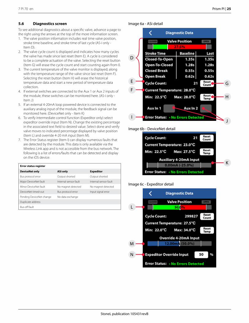
Image 5
A
B
C
5.5 More information screenTo see additional information about a specific valve, swipe right or use the arrows at the top of the device detail screen.1. At the top of the more Information screen (Image 5), the unit
model number, serial number, and date code are displayed (Item A). These are preset from the factory and cannot be changed.
2. There are two customizable text boxes titled “Valve/Actuator Description” and “Additional Information” where up to 160 characters can be added for user notes, such as maintenance or service records (Item B).
Website and instruction manualThe direct links to StoneL’s website and the unit installation, Maintenance and Operating Instructions located on the bottom buttons of the More Information screen require an internet connection to access (Item C).
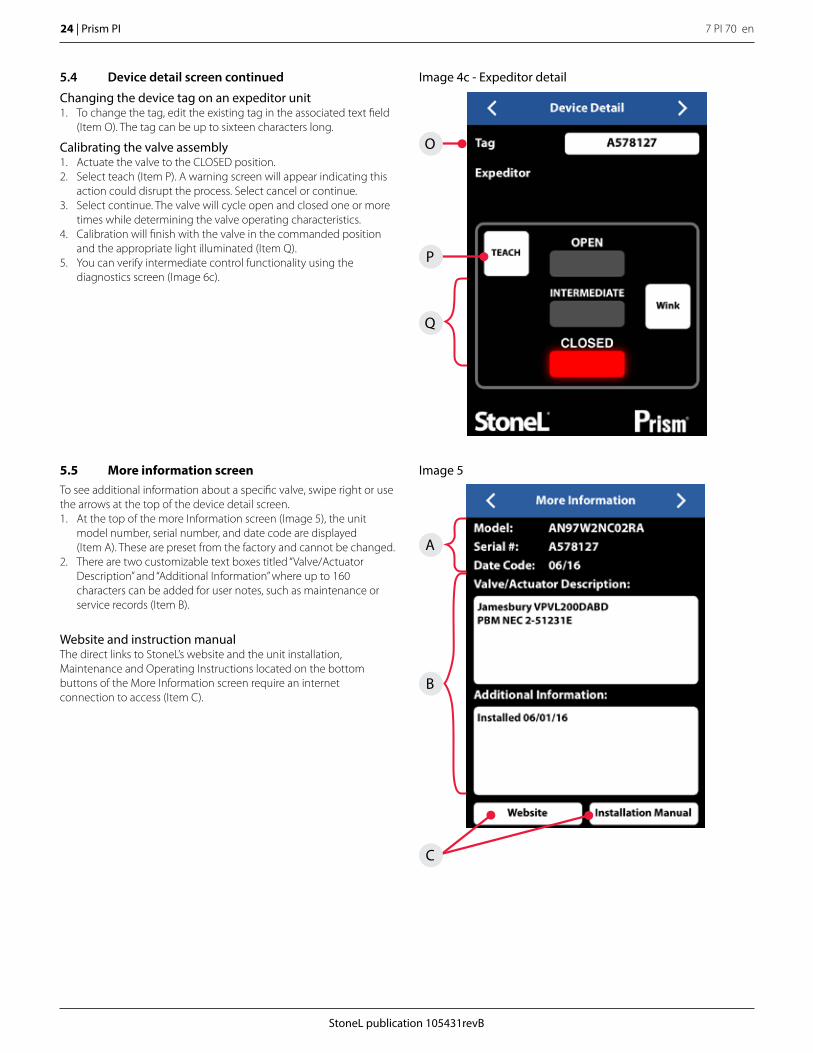
Image 4c - Expeditor detail
O
P
Q
5.4 Device detail screen continued
Changing the device tag on an expeditor unit1. To change the tag, edit the existing tag in the associated text field
(Item O). The tag can be up to sixteen characters long.
Calibrating the valve assembly1. Actuate the valve to the CLOSED position.2. Select teach (Item P). A warning screen will appear indicating this
action could disrupt the process. Select cancel or continue. 3. Select continue. The valve will cycle open and closed one or more
times while determining the valve operating characteristics. 4. Calibration will finish with the valve in the commanded position
and the appropriate light illuminated (Item Q).5. You can verify intermediate control functionality using the
diagnostics screen (Image 6c).
StoneL publication 105431revB
7 PI 70 en Prism PI | 25
D
E
F
L
M
N
I
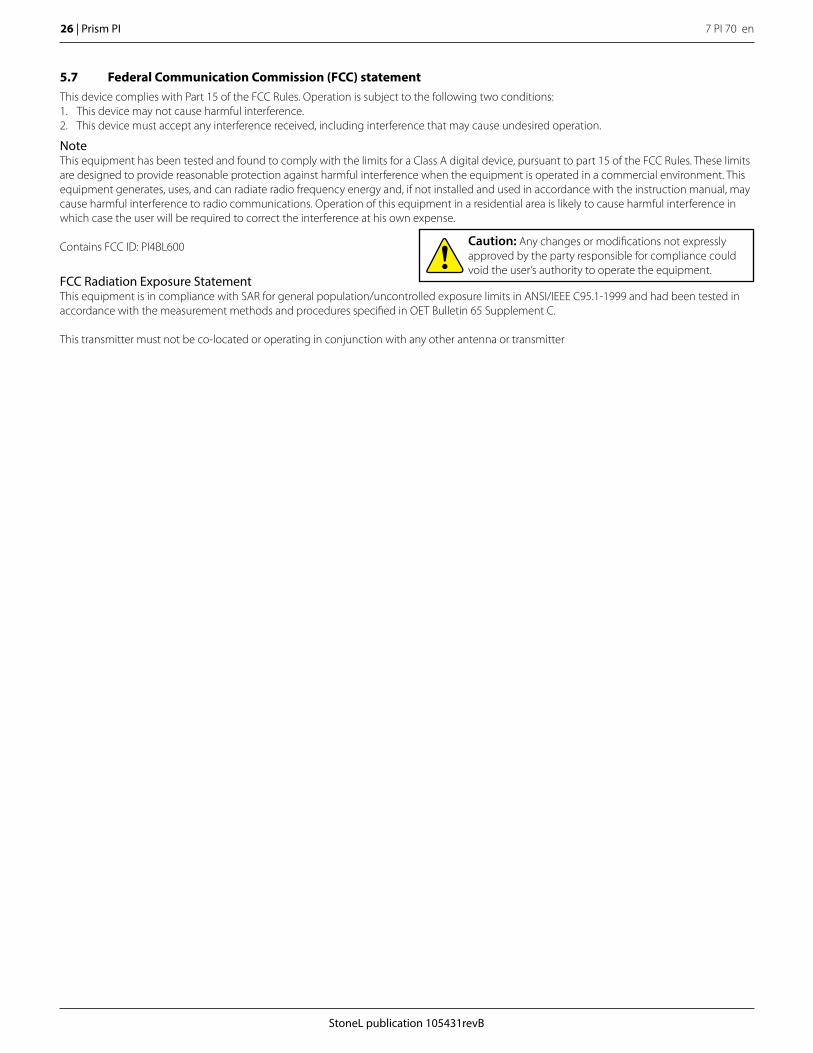
Error status register
DeviceNet only ASi only Expeditor
Bus protocol error Output shorted Output shorted
Major DeviceNet fault Internal sensor fault Internal sensor fault
Minor DeviceNet fault No magnet detected No magnet detected
DeviceNet timed-out Bus protocol error Input signal error
Pending DeviceNet change No data exchange
Duplicate address
Bus-off fault
Image 6a - ASi detail
Image 6c - Expeditor detail
Image 6b - DeviceNet detail
H
K
G
J
5.6 Diagnostics screenTo see additional diagnostics about a specific valve, advance a page to the right using the arrows at the top of the more information screen.1. The valve position information includes real time valve position,
stroke time baseline, and stroke time of last cycle (AS-i only - Item D).
2. The valve cycle count is displayed and indicates how many cycles the valve has made since last reset (Item E). A cycle is considered to be a complete actuation of the valve. Selecting the reset button (Item G) will erase the cycle count and start counting again from 0.
3. The current temperature of the valve monitor is displayed; along with the temperature range of the valve since last reset (Item F). Selecting the reset button (Item H) will erase the historical temperature data and start a new period of temperature data collection.
4. If external switches are connected to the Aux 1 or Aux 2 inputs of the module, these switches can be monitored here. (AS-i only - Item J)
5. If an external 4-20mA loop powered device is connected to the auxiliary analog input of the module, the feedback signal can be monitored here. (DeviceNet only - Item K)
6. To verify intermediate control function (Expeditor only) select expeditor override input (Item N). Change the existing percentage in the associated text field to desired value. Select done and verify valve moves to indicated percentage displayed by valve position (Item L) and override 4-20 mA input (Item M).
7. The Error Status register (Item I) can display numerous faults that are detected by the module. This data is only available via the Wireless Link app and is not accessible from the bus network. The following is a list of errors/faults that can be detected and display on the iOS device:
7 PI 70 en26 | Prism PI
StoneL publication 105431revB
5.7 Federal Communication Commission (FCC) statementThis device complies with Part 15 of the FCC Rules. Operation is subject to the following two conditions:1. This device may not cause harmful interference.2. This device must accept any interference received, including interference that may cause undesired operation.
NoteThis equipment has been tested and found to comply with the limits for a Class A digital device, pursuant to part 15 of the FCC Rules. These limits are designed to provide reasonable protection against harmful interference when the equipment is operated in a commercial environment. This equipment generates, uses, and can radiate radio frequency energy and, if not installed and used in accordance with the instruction manual, may cause harmful interference to radio communications. Operation of this equipment in a residential area is likely to cause harmful interference in which case the user will be required to correct the interference at his own expense.
Contains FCC ID: PI4BL600
FCC Radiation Exposure StatementThis equipment is in compliance with SAR for general population/uncontrolled exposure limits in ANSI/IEEE C95.1-1999 and had been tested in accordance with the measurement methods and procedures specified in OET Bulletin 65 Supplement C.
This transmitter must not be co-located or operating in conjunction with any other antenna or transmitter
Caution: Any changes or modifications not expressly approved by the party responsible for compliance could void the user’s authority to operate the equipment.
StoneL publication 105431revB
7 PI 70 en Prism PI | 27
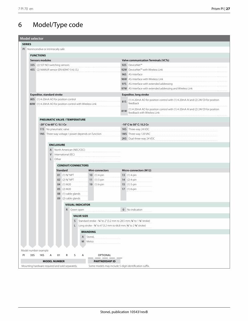
6 Model/Type code
Model selectorSERIES
PI Nonincendive or intrinsically safe
FUNCTIONS
Sensors modules Valve communication Terminals (VCTs)
33S (2) SST NO switching sensors 92S DeviceNet™
45S (2) NAMUR sensor (EN 60947-5-6; I.S.) 92W DeviceNet™ with Wireless Link
96S AS-Interface
96W AS-Interface with Wireless Link
97S AS-Interface with extended addressing
97W AS-Interface with extended addressing and Wireless Link
Expeditor, standard stroke Expeditor, long stroke
80S (1) 4-20mA AO for position control81S (1) 4-20mA AO for position control with (1) 4-20mA AI and (2) 24V DI for position
feedback80W (1) 4-20mA AO for position control with Wireless Link
81W (1) 4-20mA AO for position control with (1) 4-20mA AI and (2) 24V DI for position feedback with Wireless Link
PNEUMATIC VALVE / TEMPERATURE
-20° C to 60° C / 0.1 Cv -10° C to 50° C / 0.2 Cv
11S No pneumatic valve 1KS Three-way 24 VDC
1NS Three-way voltage / power depends on function 1MS Three-way 120 VAC
2KS Dual three-way 24 VDC
ENCLOSURE
A North American (NEC/CEC)
V International (IEC)
L Other
CONDUIT/CONNECTORS
Standard Mini-connectors Micro-connectors (M12)
01 (1) 1/2” NPT 10 (1) 4-pin 13 (1) 4-pin
02 (2) 1/2” NPT 11 (1) 5-pin 14 (2) 4-pin
04 (1) M20 19 (1) 6-pin 15 (1) 5-pin
05 (2) M20 17 (1) 6-pin
08 (1) cable glands
09 (2) cable glands
VISUAL INDICATOR
R Green open 0 No indication
VALVE SIZE
S Standard stroke - 1/4” to 2” (3.2 mm to 28.5 mm; 1/8” to 1 1/8” stroke)
L Long stroke - 1/4” to 6” (3.2 mm to 66.8 mm; 1/8” to 2 5/8” stroke)
BRANDING
A StoneL
M Metso
Model number example
PI 33S 1KS A 01 R S A OPTIONAL
MODEL NUMBER PARTNERSHIP ID
Mounting hardware required and sold separately. Some models may include 5-digit identification suffix.

7 PI 70 en28 | Prism PI
StoneL publication 105431revB
105455revA
DECLARATION OF CONFORMITY Manufacturer: StoneL 26271 US Highway 59 Fergus Falls, Minnesota 56537 USA Products: Prism PI Series – Valve Position Monitors and Valve Communication Terminals Model - Type Certificates / Directives / Standards Marking PI Series
EU Type Examination Certificate FM18ATEX0043X ATEX 2014/34/EU EN 60079-0:2012+A11:2013, EN 60079-11:2012 EMC 2014/30/EU EN 60947-5-2:2007/A1:2012
ATEX II 1 G Ex ia IIC T5 Ga ATEX II 1 D Ex ia IIIC T100°C Da
PI Series
IECEx Certificate of Conformity IECEx FMG 18.0017X IEC 60079-11, IEC60079-11:2011
Ex ia IIC T5 Ga Ex ia IIIC T100°C Da
PI Series
EMC 2014/30/EU, LVD 2014/35/EU EN 60947-5-2:2007/A1:2012 EN 62026-2:2013, EN 62026-3:2009, EN 61000-6-2:2005, EN 61000-6-4:2005, EN 61326-1:2013 RED 2014/53/EU EN 61326-1:2013, EN 61000-6-2:2005, EN 61000-6-4:2007, EN 62026-2:2013, EN 61010-2-201:2013/AC:2013, EN 62311:2008, EN 62479:2010, EN 301 489-1 v2.2.0 (2017-03), EN 301 489-17 v3.2.0 (2017-03), EN 300 328 v2.1.1 (2016-11)
ATEX Notified Bodies for EU Type Examination Certificates: FM Approvals Ltd. Windsor, Berkshire, UK (Notified Body Number 1725) Quality Assurance Certificates: ISO 9001:2015…………………………...TUV SUD America Inc. QAN FM06ATEXQ0013………………….FM Approvals (Notified Body Number 1725) QAR GB/FME/QAR11.0003……….…….FM Approvals (Notified Body Number 1725)
We declare under our sole responsibility that the products, as described, are in conformity with the listed standards and directives.
Fergus Falls, 1st July 2018
Bryan Beckman, Quality Manager Authorized Person of the Manufacturer
7 Regulatory, specific conditions of use, and product marking
StoneL publication 105431revB
7 PI 70 en Prism PI | 29
105455revA
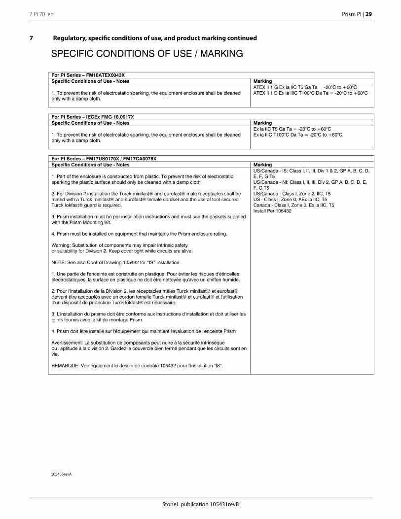
SPECIFIC CONDITIONS OF USE / MARKING For PI Series – FM18ATEX0043X Specific Conditions of Use - Notes Marking 1. To prevent the risk of electrostatic sparking, the equipment enclosure shall be cleaned only with a damp cloth.
ATEX II 1 G Ex ia IIC T5 Ga Ta = -20°C to +60°C ATEX II 1 D Ex ia IIIC T100°C Da Ta = -20°C to +60°C
For PI Series – IECEx FMG 18.0017X Specific Conditions of Use - Notes Marking 1. To prevent the risk of electrostatic sparking, the equipment enclosure shall be cleaned only with a damp cloth.
Ex ia IIC T5 Ga Ta = -20°C to +60°C Ex ia IIIC T100°C Da Ta = -20°C to +60°C
For PI Series – FM17US0170X / FM17CA0078X Specific Conditions of Use - Notes Marking 1. Part of the enclosure is constructed from plastic. To prevent the risk of electrostatic sparking the plastic surface should only be cleaned with a damp cloth. 2. For Division 2 installation the Turck minifast® and eurofast® male receptacles shall be mated with a Turck minifast® and eurofast® female cordset and the use of tool secured Turck lokfast® guard is required. 3. Prism installation must be per installation instructions and must use the gaskets supplied with the Prism Mounting Kit. 4. Prism must be installed on equipment that maintains the Prism enclosure rating. Warning: Substitution of components may impair intrinsic safety or suitability for Division 2. Keep cover tight while circuits are alive. NOTE: See also Control Drawing 105432 for “IS” installation. 1. Une partie de l'enceinte est construite en plastique. Pour éviter les risques d'étincelles électrostatiques, la surface en plastique ne doit être nettoyée qu'avec un chiffon humide. 2. Pour l'installation de la Division 2, les réceptacles mâles Turck minifast® et eurofast® doivent être accouplés avec un cordon femelle Turck minifast® et eurofast® et l'utilisation d'un dispositif de protection Turck lokfast® est nécessaire. 3. L'installation du prisme doit être conforme aux instructions d'installation et doit utiliser les joints fournis avec le kit de montage Prism. 4. Prism doit être installé sur l'équipement qui maintient l'évaluation de l'enceinte Prism Avertissement: La substitution de composants peut nuire à la sécurité intrinsèque ou l'aptitude à la division 2. Gardez le couvercle bien fermé pendant que les circuits sont en vie. REMARQUE: Voir également le dessin de contrôle 105432 pour l'installation "IS".
US/Canada - IS: Class I, II, III, Div 1 & 2, GP A, B, C, D, E, F, G T5 US/Canada - NI: Class I, II, III, Div 2, GP A, B, C, D, E, F, G T5 US/Canada - Class I, Zone 2, IIC, T5 US - Class I, Zone 0, AEx ia IIC, T5 Canada - Class I, Zone 0, Ex ia IIC, T5 Install Per 105432
7 Regulatory, specific conditions of use, and product marking continued
7 PI 70 en30 | Prism PI
StoneL publication 105431revB
I.S. C
ON
TRO
L, P
RIS
M P
I SER
IES
NS
9/1/
2016
KK RB NK
1054
32SH
EET
2A
TOLE
RA
NC
ES
(UN
LES
S O
THE
RW
ISE
SPEC
IFIE
D):
X.
XXX
±.0
05
AN
GLE
S±
0° 3
0'
X.XX
±.0
10
F
INIS
H f
125
RM
S
X/X
±.0
15A
1SC
ALE
RE
V.
DR
AWIN
G N
O.
SIZE
TITL
E
APPD
.
CH
K.
DR
.
DA
TE
CONF
IDEN
TIAL
THIS
DRA
WIN
G AN
D AL
L INF
ORMA
TION
CON
TAIN
EDHE
REIN
IS T
HE P
ROPE
RTY
OF A
ND IS
SUB
JECT
TO
CHAN
GE B
Y ST
ONEL
. DRA
WIN
G IS
NOT
TO
BERE
PROD
UCED
OR
REVE
ALED
TO A
NY O
THER
PAR
TYUN
LESS
AUT
HORI
ZED
BY S
TONE
L.ME
TSO
AUTO
MATIO
N, FE
RGUS
FALL
S, M
N U.
S.A.
REVISIONS
OF
REV
ISIO
NEC
OD
ATE
BY
(6) O
PEN
-(5
) OPE
N +
(3) S
OL
PW
R +
(4) S
OL
PW
R -
Pris
mM
odul
e
HAZ
ARD
OU
S(C
LASS
IFIE
D)
LOC
ATIO
NSt
oneL
Enc l
osur
e
NAM
UR
Barri
er
Sole
noid
Coi
lBa
rrie
r
(7) C
LOS
ED +
NA
MU
RBa
rrier
(8) C
LOS
ED -
Intri
nsic
ally
Saf
eG
roun
d
NO
N-H
AZAR
DO
US
(SA
FE A
REA
)LO
CAT
ION
Use
r Sup
plie
dI.S
. Sol
enoi
d
(2) S
OL
OU
T -
(1) S
OL
OU
T +
INST
ALL
ATI
ON
NO
TES:
(US
- Cla
ss I,
II, I
II, D
ivis
ion
1 &
2, G
roup
s A
, B, C
, D, E
, F, G
T5;
Cla
ss I
/ Zon
e 0
/ AE
x ia
IIC
T5)
(Can
ada
- Cla
ss I,
II, I
II, D
ivis
ion
1 &
2, G
roup
s A,
B, C
, D, E
, F, G
T5;
Cla
ss I
/ Zon
e 0
/ Ex
ia II
C T
5)
Entit
y Pa
ram
eter
s:Se
nsor
s:U
i (V
max
) = 2
2 VD
C; I
i (Im
ax) =
120
mA;
Pi =
0.4
W; C
i = 3
nF;
Li =
0 H
Sole
noid
Jun
ctio
n Te
rmin
als:
Ui (
Vm
ax) =
28
VDC
; Ii (
Imax
) = 1
20 m
A; C
i_ju
nctio
n* =
0 F
; Li_
junc
tion*
= 0
H* S
olen
oid
inst
alla
tion
shal
l mee
t: C
a″
Ci_
sole
noid
+ C
i_ju
nctio
n +
Cca
ble;
La
″ Li
_sol
enoi
d +
Li_j
unct
ion
+ Lc
able
;
1. T
he A
ssoc
iate
d Ap
para
tus
mus
t be
FM A
ppro
ved.
2. T
he E
ntity
Con
cept
allo
ws
inte
rcon
nect
ion
of in
trins
ical
ly s
afe
appa
ratu
s w
ith a
ssoc
iate
d ap
para
tus
whe
n th
efo
llow
ing
is tr
ue: V
oc, V
t or U
o <
Ui (
Vmax
); Is
c, It
or I
o <
Ii (Im
ax);
Ca
> C
i + C
cabl
e; L
a >
Li +
Lca
ble.
3. D
ust-t
ight
con
duit
seal
mus
t be
used
whe
n in
stal
led
in C
lass
II a
nd C
lass
III e
nviro
nmen
ts.
4. C
ontro
l equ
ipm
ent c
onne
cted
to b
arrie
r mus
t not
use
or g
ener
ate
mor
e th
an 2
50 V
rms
or V
dc.
5. In
stal
latio
n sh
ould
be
in a
ccor
danc
e w
ith A
NS
I/IS
A R
PA1
2.06
.01
"Inst
alla
tion
of In
trins
ical
ly S
afe
Syst
ems
for
Haz
ardo
us (C
lass
ified
) Loc
atio
ns" a
nd th
e N
atio
nal E
lect
rical
Cod
e (A
NSI
/NFP
A 70
) or i
n ac
cord
ance
with
the
Can
adia
n E
lect
ric C
ode.
6. A
ssoc
iate
d ap
para
tus
man
ufac
ture
r's in
stal
latio
n dr
awin
g m
ust b
e fo
llow
ed w
hen
inst
allin
g th
is e
quip
men
t.7.
To
mai
ntai
n in
trins
ic s
afet
y, w
iring
ass
ocia
ted
with
eac
h se
nsor
or s
olen
oid
coil
wiri
ng m
ust b
e ru
n in
sep
arat
eca
bles
or s
epar
ate
shie
lds
conn
ecte
d to
intri
nsic
ally
saf
e (a
ssoc
iate
d ap
para
tus)
gro
und.
8. C
ondu
it G
roun
ding
- U
pon
inst
alla
tion
verif
y el
ectri
cal c
ontin
uity
bet
wee
n co
ndui
t and
gro
und
term
inal
.9.
Res
ista
nce
betw
een
Intri
nsic
Saf
e G
roun
d an
d ea
rth g
roun
d m
ust b
e le
ss th
an o
ne o
hm.
Spec
ific
Con
ditio
ns o
f Use
:1.
Par
t of t
he e
nclo
sure
is c
onst
ruct
ed fr
om p
last
ic. T
o pr
even
t the
risk
of e
lect
rost
atic
spa
rkin
g th
e pl
astic
sur
face
shou
ld o
nly
be c
lean
ed w
ith a
dam
p cl
oth.
2. F
or D
ivis
ion
2 in
stal
latio
n th
e Tu
rck
min
ifast
® a
nd e
urof
ast®
mal
e re
cept
acle
s sh
all b
e m
ated
with
a T
urck
min
ifast
and
euro
fast
fem
ale
cord
set a
nd th
e us
e of
tool
sec
ured
Tur
ck lo
kfas
t® g
uard
is re
quire
d.3.
Pris
m in
stal
latio
n m
ust b
e pe
r ins
talla
tion
inst
ruct
ions
and
mus
t use
the
gask
ets
supp
lied
with
the
Pris
m M
ount
ing
Kit.
4. P
rism
mus
t be
inst
alle
d on
equ
ipm
ent t
hat m
aint
ains
the
Pris
m e
nclo
sure
ratin
g.
INST
ALL
ATI
ON
NO
TES:
(II 1
G E
x ia
IIC
T5
Ga
/ II 1
D E
x ia
IIIC
T10
0°C
Da)
Entit
y Pa
ram
eter
s:Se
nsor
s:U
i (Vm
ax) =
22
VDC
; Ii (
Imax
) = 1
20 m
A; P
i = 0
.4 W
; Ci =
3 n
F; L
i = 0
HSo
leno
id J
unct
ion
Term
inal
s:U
i (V
max
) = 2
8 VD
C; I
i (Im
ax) =
120
mA;
Ci_
junc
tion*
= 0
F; L
i_ju
nctio
n* =
0 H
* Sol
enoi
d in
stal
latio
n sh
all m
eet:
Ca
″ C
i_so
leno
id +
Ci_
junc
tion
+ C
cabl
e; L
a″
Li_s
olen
oid
+ Li
_jun
ctio
n +
Lcab
le;
1. T
he A
ssoc
iate
d A
ppar
atus
mus
t be
FM A
ppro
ved.
2. T
he E
ntity
Con
cept
allo
ws
inte
rcon
nect
ion
of in
trins
ical
ly s
afe
appa
ratu
s w
ith a
ssoc
iate
d ap
para
tus
whe
n th
efo
llow
ing
is tr
ue: V
oc, V
t or U
o <
Ui (
Vm
ax);
Isc,
It o
r Io
< Ii
(Imax
); C
a >
Ci +
Cca
ble;
La
> Li
+ L
cabl
e.3.
Dus
t-tig
ht c
ondu
it se
al m
ust b
e us
ed w
hen
inst
alle
d in
Cla
ss II
and
Cla
ss II
I env
ironm
ents
.4.
Con
trol e
quip
men
t con
nect
ed to
bar
rier m
ust n
ot u
se o
r gen
erat
e m
ore
than
250
Vrm
s or
Vdc
.5.
Inst
alla
tion
shou
ld b
e in
acc
orda
nce
with
app
ropr
iate
loca
l cod
e an
d pr
actic
e.6.
Ass
ocia
ted
appa
ratu
s m
anuf
actu
rer's
inst
alla
tion
draw
ing
mus
t be
follo
wed
whe
n in
stal
ling
this
equ
ipm
ent.
7. T
o m
aint
ain
intri
nsic
saf
ety,
wiri
ng a
ssoc
iate
d w
ith e
ach
sens
or o
r sol
enoi
d co
il w
iring
mus
t be
run
in s
epar
ate
cabl
es o
r sep
arat
e sh
ield
s co
nnec
ted
to in
trins
ical
ly s
afe
(ass
ocia
ted
appa
ratu
s) g
roun
d.8.
Con
duit
Gro
undi
ng -
Upo
n in
stal
latio
n ve
rify
elec
trica
l con
tinui
ty b
etw
een
cond
uit a
nd g
roun
d te
rmin
al.
9. R
esis
tanc
e be
twee
n In
trins
ic S
afe
Gro
und
and
earth
gro
und
mus
t be
less
than
one
ohm
.
Spec
ific
Con
ditio
ns o
f Use
:1.
To
prev
ent t
he ri
sk o
f ele
ctro
stat
ic s
park
ing,
the
equi
pmen
t enc
losu
re s
hall
be c
lean
ed o
nly
with
a d
amp
clot
h.
PI45
S11
A09
/13/
18BK
1175
2
Con
trol
Equi
pmen
t
Intri
nsic
Saf
ety
Barri
er(A
ssoc
iate
d Ap
para
tus)
Sep
arat
eS
hiel
ds
Pass
-thru
Sol
enoi
dJu
nctio
n w
ith in
fallib
le L
ED
8 Appendix8.1 Controlled installation drawings
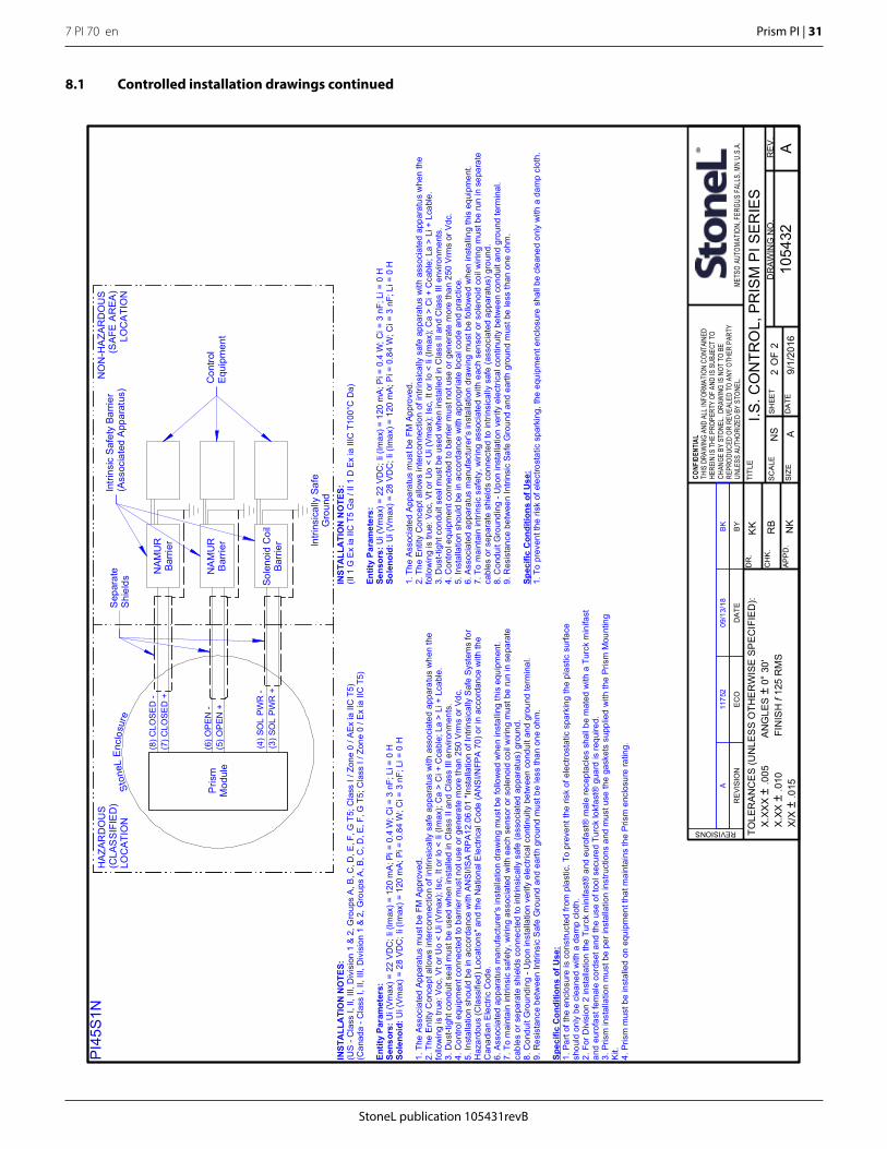
StoneL publication 105431revB
7 PI 70 en Prism PI | 31
I.S. C
ON
TRO
L, P
RIS
M P
I SER
IES
NS
9/1/
2016
KK RB NK
1054
32SH
EET
2A
TOLE
RA
NC
ES
(UN
LES
S O
THE
RW
ISE
SPEC
IFIE
D):
X.
XXX
±.0
05
AN
GLE
S±
0° 3
0'
X.XX
±.0
10
F
INIS
H f
125
RM
S
X/X
±.0
15A
2SC
ALE
RE
V.
DR
AWIN
G N
O.
SIZE
TITL
E
APPD
.
CH
K.
DR
.
DA
TE
CONF
IDEN
TIAL
THIS
DRA
WIN
G AN
D AL
L INF
ORMA
TION
CON
TAIN
EDHE
REIN
IS T
HE P
ROPE
RTY
OF A
ND IS
SUB
JECT
TO
CHAN
GE B
Y ST
ONEL
. DRA
WIN
G IS
NOT
TO
BERE
PROD
UCED
OR
REVE
ALED
TO A
NY O
THER
PAR
TYUN
LESS
AUT
HORI
ZED
BY S
TONE
L.ME
TSO
AUTO
MATIO
N, FE
RGUS
FALL
S, M
N U.
S.A.
REVISIONS
OF
REV
ISIO
NEC
OD
ATE
BY
HAZ
ARD
OU
S(C
LAS
SIFI
ED
)LO
CAT
ION
NO
N-H
AZA
RD
OU
S(S
AFE
AR
EA)
LOC
ATI
ON
(8) C
LOSE
D -
(7) C
LOSE
D +
Intri
nsic
ally
Saf
eG
roun
d
(5) O
PEN
+(6
) OPE
N -
Ston
eLE
nclo
sure
(3) S
OL
PWR
+(4
) SO
L PW
R -
Pris
mM
odul
e
NAM
UR
Barri
er
Sole
noid
Coi
lBa
rrie
r
NA
MU
RBa
rrier
A09
/13/
18BK
1175
2
Con
trol
Equi
pmen
t
Intri
nsic
Saf
ety
Barri
er(A
ssoc
iate
d A
ppar
atus
)Se
para
teSh
ield
s
PI45
S1N
INST
ALL
ATI
ON
NO
TES:
(US
- Cla
ss I,
II, I
II, D
ivis
ion
1 &
2, G
roup
s A
, B, C
, D, E
, F, G
T5;
Cla
ss I
/ Zon
e 0
/ AEx
ia II
C T
5)(C
anad
a - C
lass
I, II
, III,
Div
isio
n 1
& 2,
Gro
ups
A, B
, C, D
, E, F
, G T
5; C
lass
I / Z
one
0 / E
x ia
IIC
T5)
Entit
y Pa
ram
eter
s:Se
nsor
s:U
i (Vm
ax) =
22
VDC
; Ii (
Imax
) = 1
20 m
A; P
i = 0
.4 W
; Ci =
3 n
F; L
i = 0
HSo
leno
id:U
i (V
max
) = 2
8 VD
C; I
i (Im
ax) =
120
mA;
Pi =
0.8
4 W
; Ci =
3 n
F; L
i = 0
H
1. T
he A
ssoc
iate
d Ap
para
tus
mus
t be
FM A
ppro
ved.
2. T
he E
ntity
Con
cept
allo
ws
inte
rcon
nect
ion
of in
trins
ical
ly s
afe
appa
ratu
s w
ith a
ssoc
iate
d ap
para
tus
whe
n th
efo
llow
ing
is tr
ue: V
oc, V
t or U
o <
Ui (
Vm
ax);
Isc,
It o
r Io
< Ii
(Imax
); C
a >
Ci +
Cca
ble;
La
> Li
+ L
cabl
e.3.
Dus
t-tig
ht c
ondu
it se
al m
ust b
e us
ed w
hen
inst
alle
d in
Cla
ss II
and
Cla
ss II
I env
ironm
ents
.4.
Con
trol e
quip
men
t con
nect
ed to
bar
rier m
ust n
ot u
se o
r gen
erat
e m
ore
than
250
Vrm
s or
Vdc
.5.
Inst
alla
tion
shou
ld b
e in
acc
orda
nce
with
AN
SI/IS
A R
PA1
2.06
.01
"Inst
alla
tion
of In
trins
ical
ly S
afe
Syst
ems
for
Haz
ardo
us (C
lass
ified
) Loc
atio
ns" a
nd th
e N
atio
nal E
lect
rical
Cod
e (A
NS
I/NFP
A 70
) or i
n ac
cord
ance
with
the
Can
adia
n E
lect
ric C
ode.
6. A
ssoc
iate
d ap
para
tus
man
ufac
ture
r's in
stal
latio
n dr
awin
g m
ust b
e fo
llow
ed w
hen
inst
allin
g th
is e
quip
men
t.7.
To
mai
ntai
n in
trins
ic s
afet
y, w
iring
ass
ocia
ted
with
eac
h se
nsor
or s
olen
oid
coil
wiri
ng m
ust b
e ru
n in
sep
arat
eca
bles
or s
epar
ate
shie
lds
conn
ecte
d to
intri
nsic
ally
saf
e (a
ssoc
iate
d ap
para
tus)
gro
und.
8. C
ondu
it G
roun
ding
- U
pon
inst
alla
tion
verif
y el
ectri
cal c
ontin
uity
bet
wee
n co
ndui
t and
gro
und
term
inal
.9.
Res
ista
nce
betw
een
Intri
nsic
Saf
e G
roun
d an
d ea
rth g
roun
d m
ust b
e le
ss th
an o
ne o
hm.
Spec
ific
Con
ditio
ns o
f Use
:1.
Par
t of t
he e
nclo
sure
is c
onst
ruct
ed fr
om p
last
ic. T
o pr
even
t the
risk
of e
lect
rost
atic
spa
rkin
g th
e pl
astic
sur
face
shou
ld o
nly
be c
lean
ed w
ith a
dam
p cl
oth.
2. F
or D
ivis
ion
2 in
stal
latio
n th
e Tu
rck
min
ifast
® a
nd e
urof
ast®
mal
e re
cept
acle
s sh
all b
e m
ated
with
a T
urck
min
ifast
and
euro
fast
fem
ale
cord
set a
nd th
e us
e of
tool
sec
ured
Tur
ck lo
kfas
t® g
uard
is re
quire
d.3.
Pris
m in
stal
latio
n m
ust b
e pe
r ins
talla
tion
inst
ruct
ions
and
mus
t use
the
gask
ets
supp
lied
with
the
Pris
m M
ount
ing
Kit.
4. P
rism
mus
t be
inst
alle
d on
equ
ipm
ent t
hat m
aint
ains
the
Pris
m e
nclo
sure
ratin
g.
INST
ALL
ATI
ON
NO
TES:
(II 1
G E
x ia
IIC
T5
Ga
/ II 1
D E
x ia
IIIC
T10
0°C
Da)
Entit
y Pa
ram
eter
s:Se
nsor
s:U
i (V
max
) = 2
2 VD
C; I
i (Im
ax) =
120
mA;
Pi =
0.4
W; C
i = 3
nF;
Li =
0 H
Sole
noid
:Ui (
Vm
ax) =
28
VDC
; Ii (
Imax
) = 1
20 m
A; P
i = 0
.84
W; C
i = 3
nF;
Li =
0 H
1. T
he A
ssoc
iate
d Ap
para
tus
mus
t be
FM A
ppro
ved.
2. T
he E
ntity
Con
cept
allo
ws
inte
rcon
nect
ion
of in
trins
ical
ly s
afe
appa
ratu
s w
ith a
ssoc
iate
d ap
para
tus
whe
n th
efo
llow
ing
is tr
ue: V
oc, V
t or U
o <
Ui (
Vmax
); Is
c, It
or I
o <
Ii (Im
ax);
Ca
> C
i + C
cabl
e; L
a >
Li +
Lca
ble.
3. D
ust-t
ight
con
duit
seal
mus
t be
used
whe
n in
stal
led
in C
lass
II a
nd C
lass
III e
nviro
nmen
ts.
4. C
ontro
l equ
ipm
ent c
onne
cted
to b
arrie
r mus
t not
use
or g
ener
ate
mor
e th
an 2
50 V
rms
or V
dc.
5. In
stal
latio
n sh
ould
be
in a
ccor
danc
e w
ith a
ppro
pria
te lo
cal c
ode
and
prac
tice.
6. A
ssoc
iate
d ap
para
tus
man
ufac
ture
r's in
stal
latio
n dr
awin
g m
ust b
e fo
llow
ed w
hen
inst
allin
g th
is e
quip
men
t.7.
To
mai
ntai
n in
trins
ic s
afet
y, w
iring
ass
ocia
ted
with
eac
h se
nsor
or s
olen
oid
coil
wiri
ng m
ust b
e ru
n in
sep
arat
eca
bles
or s
epar
ate
shie
lds
conn
ecte
d to
intri
nsic
ally
saf
e (a
ssoc
iate
d ap
para
tus)
gro
und.
8. C
ondu
it G
roun
ding
- U
pon
inst
alla
tion
verif
y el
ectri
cal c
ontin
uity
bet
wee
n co
ndui
t and
gro
und
term
inal
.9.
Res
ista
nce
betw
een
Intri
nsic
Saf
e G
roun
d an
d ea
rth g
roun
d m
ust b
e le
ss th
an o
ne o
hm.
Spec
ific
Con
ditio
ns o
f Use
:1.
To
prev
ent t
he ri
sk o
f ele
ctro
stat
ic s
park
ing,
the
equi
pmen
t enc
losu
re s
hall
be c
lean
ed o
nly
with
a d
amp
clot
h.
8.1 Controlled installation drawings continued

StoneL Production CenterNorth America, 26271 US Hwy 59, Fergus Falls, MN 56537, USA. Tel. +1 218 739 5774. Fax +1 218 739 5776
www.StoneL.com
Metso Flow Control Inc. South Korea, 235 Cheomdansaneop 1-ro, Daesowon-myeon, Chungju-si, Chungbuk-do, 380-871, Korea Tel. +82 43 852 7708, Fax +82 43 841 9890
Europe,Vanha Porvoontie 229, P.O. Box 304, FI-01301 Vantaa, Finland. Tel. +358 20 483 150. Fax +358 20 483 151North America, 44 Bowditch Drive, P.O. Box 8044, Shrewsbury, M A 01545, USA. Tel. +1 508 852 0200. Fax +1 508 852 8172
South America, Av. Independéncia, 2500-Iporanga, 18087-101, Sorocaba-São Paulo, Brazil. Tel. +55 15 2102 9700. Fax +55 15 2102 9748 Asia Pacific, 238B Thomson Road, #17-01 Novena Square Tower B, Singapore 307685. Tel. +65 6511 1011. Fax +65 6250 0830
China, 11/F, China Youth Plaza, No.19 North Rd of East 3rd Ring Rd, Chaoyang District, Beijing 100020, China. Tel. +86 10 6566 6600. Fax +86 10 6566 2583.Middle East, Roundabout 8, Unit AB-07, P.O. Box 17175, Jebel Ali Freezone, Dubai, United Arab Emirates. Tel. +971 4 883 6974. Fax +971 4 883 6836
www.metso.com/valves
Subject to change without notice