Embed Size (px)
Citation preview
PRISMA – AN AUTONOMOUS FORMATION FLYING MISSION
Staffan Persson(1)
, Per Bodin(1)
, Eberhard Gill(2)
, Jon Harr(3)
, John Jörgensen(4)
(1)Swedish Space Corporation (SSC), S- 17104 Solna, Sweden, Email: [email protected], [email protected]
(2) German Aerospace Center (DLR), D-82230 Wessling, Germany, Email: [email protected] (3)
Centre National d’Etudes Spaciale (CNES), France,Email: [email protected] (4)
Danish Technical University (DTU),Lyngby, Denmark, Email: [email protected]
ABSTRACT
PRISMA is an ongoing satellite project comprising two
satellites. The project constitutes an in-orbit test bed for
Guidance, Navigation and Control (GNC) algorithms
and sensors for advanced closed-loop formation flying
and rendezvous. The satellites will be launched in a
low earth orbit and carry out a series of maneuvering
experiments and sensor experiments during a mission
time of 8-10 months. Autonomous formation flying in
decimeter precision will be demonstrated using relative
GPS and Formation Flying RF metrology instruments.
Vision based methods using a modified star camera
will demonstrate autonomous homing and rendezvous
from hundreds of kilometers down to close proximity.
Proximity operations based on GPS or optical
information shall be demonstrated all the way down to
almost physical contact.
A new environmentally friendly, non-toxic chemical
propulsion system as well as a new MEMS micro-
thruster system will be flight demonstrated.
1. INTRODUCTION
There are a number of planned missions and mission
concepts that request several satellites in various modes
of cooperation. This may be interferometer missions
like Darwin, on-orbit inspection and service missions
like CX-OLEV, or automated rendezvous missions like
Mars Sample and Return. This in turn needs
developments within critical technologies such as
guidance, navigation and control (GNC) and sensor
technology.
In Europe, several organizations have made plans for
entering the multi-satellite and formation flying
discipline, but until quite recent, there has been no real
project planned.
Recognizing the need for a forceful initiative, the
Swedish National Space Board (SNSB) and Swedish
Space Corporation (SSC) created the PRISMA
mission. PRISMA is a combination of a Formation
Flying (FF) and Rendezvous (RV) technology test bed,
and a technology flight for several subsystems under
development by SSC and other Swedish industries. The
FF and RV part of the mission would utilize and
further develop the Guidance, Navigation and Control
(GNC) competence at SSC.
In order to create a strong and internationally
competitive project, several European industries were
invited to join the project, contributing with sensor
technology and GNC competence.
The project was formed in early 2005, when the
following main contributors could be registered:
• German Aerospace Center (DLR), contributing
with a GPS navigation system including GPS H/W
• Alcatel Space, later replaced by CNES,
contributing with the Formation Flying RF sensor
(FFRF)
• Danish Technical University (DTU), contributing
with a Vision Based System (VBS).
Together with motor technology experiments from two
subsidiary companies to SSC, ECAPS and Nanospace,
a core mission was formed.
2. MISSION GOALS
2.1. Primary goals
The primary goals are technology demonstrations and
maneuver experiments containing GNC and sensor
technology for a family of future missions where RV
and /or FF must be utilized. The demonstrations are:
• Autonomous Formation Flying based on a GPS
system and a Formation Flying RF sensor system
• Homing and Rendezvous based on VBS only
• Proximity Operations, based on GPS and VBS
• Final Approach and Recede Operations, based on
VBS only
These experiments contain the flight demonstration of
the GPS system, the FFRF sensor system and the VBS
system as such.
2.2. Secondary goals
The mission also has a set of drivers originating from
the Swedish national space program where different
Published 2006-10-02
developments in platform technology have been
undertaken. These are:
• Flight demonstration of the High Performance
Green Propellant (HPGP) 1-N thrusters
• Flight demonstration of the Micropropulsion
System cold gas thrusters
• Further development of the Data Handling System
and Power Distribution System
• Model based Onboard Software development
methods using Matlab/Simulink and autocode
generation methods.
• PUS and CCSDS compatible Ground Support
Equipment.
3. MISSION OVERVIEW
The mission consists of two spacecraft. One is called
MAIN and is a 3-axis stabilized, highly maneuverable
spacecraft of about 150 kg. The other spacecraft is
called TARGET and has no orbit maneuvering
capability but will act as a passive but intelligent target
for many of the maneuvering experiments of the Main
spacecraft.
The two S/C will be launched clamped together to a
sun-synchronous dawn-dusk orbit of about 700 km
altitude.
Once in orbit, a check-out phase will start with the two
S/C clamped together. Various sensor, actuator and
motor systems will be commissioned during a few
weeks. After the commissioning phase, the satellites
will be separated and the real experiment phase will
start. The experiments will be detailed in section 5.2.
The mission is designed for a very short and intensive
campaign. The baseline mission time is only 8-10
months, during which the experiments will be run as a
continuous sequence.
The mission will be controlled from a Mission Control
Centre located at SSC in Solna, with an executive
operations centre and antennas located as SSC base
Esrange in the north of Sweden. The satellites make
around 14 orbits per day, of which 10 can be seen from
Kiruna with an average contact time of 8 minutes each.
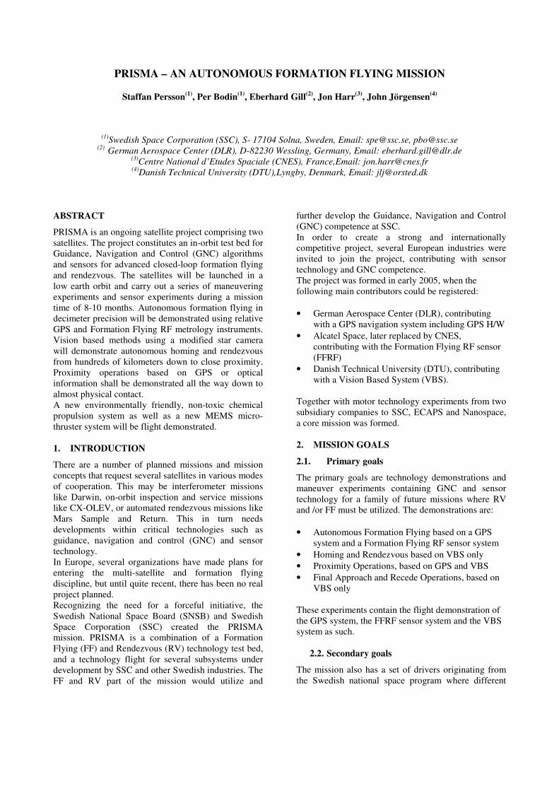
3.1. Launch configuration
The baseline launcher is a Dnepr launch vehicle from
Baikonour, where PRISMA will be secondary payload.
The launch configuration is depicted in Figure 1 under
the Dnepr fairing.
In the launch configuration, the TARGET S/C is
clamped to the MAIN upper face via a small separation
system. The complete stack weighs 200 kg and the
dimensions are roughly 800x800x1300 mm.
3.2. Nominal flight configuration
The orbit geometry is such that the sun vector is
essentially normal to the orbit plane. In a nominal
flight configuration, the MAIN is located along-track
and behind the TARGET as depicted in Figure 2. From
this basic relative position, the MAIN will assume
different positions, attitudes of motion profiles relative
to the TARGET according to the specific experiment to
be performed.
Figure 1: PRISMA stack at launch
Nadir
Sun vector Orbit track
Continuous operation in
Target-pointing mode possible outside 45°cones
Figure 2: PRISMA in flight configuration
4. SPACECRAFT DESIGN AND
ARCHITECTURE
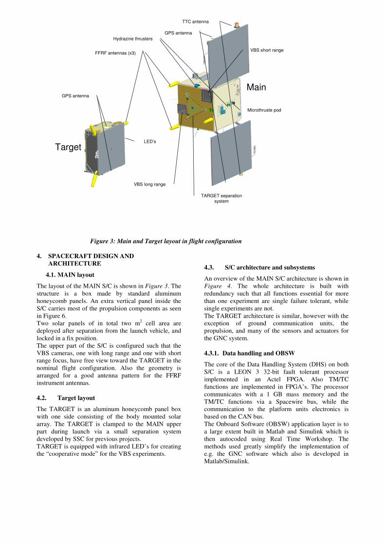
4.1. MAIN layout
The layout of the MAIN S/C is shown in Figure 3. The
structure is a box made by standard aluminum
honeycomb panels. An extra vertical panel inside the
S/C carries most of the propulsion components as seen
in Figure 6.
Two solar panels of in total two m2 cell area are
deployed after separation from the launch vehicle, and
locked in a fix position.
The upper part of the S/C is configured such that the
VBS cameras, one with long range and one with short
range focus, have free view toward the TARGET in the
nominal flight configuration. Also the geometry is
arranged for a good antenna pattern for the FFRF
instrument antennas.
4.2. Target layout
The TARGET is an aluminum honeycomb panel box
with one side consisting of the body mounted solar
array. The TARGET is clamped to the MAIN upper
part during launch via a small separation system
developed by SSC for previous projects.
TARGET is equipped with infrared LED’s for creating
the “cooperative mode” for the VBS experiments.
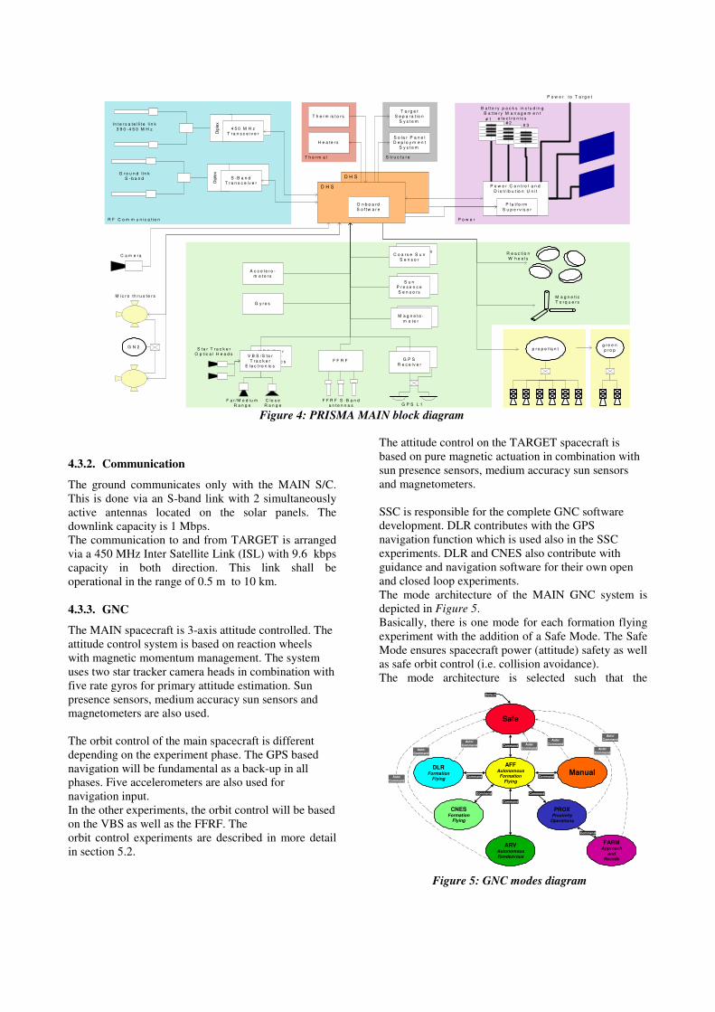
4.3. S/C architecture and subsystems
An overview of the MAIN S/C architecture is shown in
Figure 4. The whole architecture is built with
redundancy such that all functions essential for more
than one experiment are single failure tolerant, while
single experiments are not.
The TARGET architecture is similar, however with the
exception of ground communication units, the
propulsion, and many of the sensors and actuators for
the GNC system.
4.3.1. Data handling and OBSW
The core of the Data Handling System (DHS) on both
S/C is a LEON 3 32-bit fault tolerant processor
implemented in an Actel FPGA. Also TM/TC
functions are implemented in FPGA’s. The processor
communicates with a 1 GB mass memory and the
TM/TC functions via a Spacewire bus, while the
communication to the platform units electronics is
based on the CAN bus.
The Onboard Software (OBSW) application layer is to
a large extent built in Matlab and Simulink which is
then autocoded using Real Time Workshop. The
methods used greatly simplify the implementation of
e.g. the GNC software which also is developed in
Matlab/Simulink.
FFRF antennas (x3)
GPS antenna
TTC antenna
VBS long range
VBS short range
TARGET separation
system
Microthruste pod
GPS antenna
Hydrazine thrusters
Target
Main
LED’s
FFRF antennas (x3)
GPS antenna
TTC antenna
VBS long range
VBS short range
TARGET separation
system
Microthruste pod
GPS antenna
Hydrazine thrusters
Target
Main
LED’s
Figure 3: Main and Target layout in flight configuration
4.3.2. Communication
The ground communicates only with the MAIN S/C.
This is done via an S-band link with 2 simultaneously
active antennas located on the solar panels. The
downlink capacity is 1 Mbps.
The communication to and from TARGET is arranged
via a 450 MHz Inter Satellite Link (ISL) with 9.6 kbps
capacity in both direction. This link shall be
operational in the range of 0.5 m to 10 km.
4.3.3. GNC
The MAIN spacecraft is 3-axis attitude controlled. The
attitude control system is based on reaction wheels
with magnetic momentum management. The system
uses two star tracker camera heads in combination with
five rate gyros for primary attitude estimation. Sun
presence sensors, medium accuracy sun sensors and
magnetometers are also used.
The orbit control of the main spacecraft is different
depending on the experiment phase. The GPS based
navigation will be fundamental as a back-up in all
phases. Five accelerometers are also used for
navigation input.
In the other experiments, the orbit control will be based
on the VBS as well as the FFRF. The
orbit control experiments are described in more detail
in section 5.2.
The attitude control on the TARGET spacecraft is
based on pure magnetic actuation in combination with
sun presence sensors, medium accuracy sun sensors
and magnetometers.
SSC is responsible for the complete GNC software
development. DLR contributes with the GPS
navigation function which is used also in the SSC
experiments. DLR and CNES also contribute with
guidance and navigation software for their own open
and closed loop experiments.
The mode architecture of the MAIN GNC system is
depicted in Figure 5.
Basically, there is one mode for each formation flying
experiment with the addition of a Safe Mode. The Safe
Mode ensures spacecraft power (attitude) safety as well
as safe orbit control (i.e. collision avoidance).
The mode architecture is selected such that the
S t r u c tu r eT h e r m a l
D H S
P R O
P o w e r
G N C
R F C o m m u n ic a t io n
Dip
lex
S -B a n d
T r a n s c e iv e r
A c c e le r o -
m e t e r s
G y r o s
R e a c t io n
W h e e ls
M a g n e t ic
T o r q u e r s
Dip
lex
4 5 0 M H z
T r a n s c e iv e r
In te r s a te l l i t e l in k
3 9 0 - 4 5 0 M H z
G r o u n d l in k
S - b a n d
p r o p e l la n t
F F R F
S ta r T r a c k e r
O p t ic a l H e a d s
F a r /M e d iu m
R a n g e
C lo s e
R a n g e
V B S O p t ic a l
H e a d s
F F R F S - B a n d
a n te n n a s
G P S
R e c e iv e r
G P S L 1
a n te n n a s
V B S / S ta r
T r a c k e r
E le c t r o n ic s
V B S /S ta r
T r a c k e r
E le c t r o n ic s
D H S
O n b o a r d
S o f tw a r e
P o w e r C o n t ro l a n d
D is t r ib u t io n U n i t
P la t f o rm
S u p e r v is o r
B a t te r y p a c k s in c lu d in g
B a t te r y M a n a g e m e n t
e le c t r o n ic s# 1# 2
# 3
T h e r m is t o r s
H e a te r s
T a r g e t
S e p a r a t io n
S y s t e m
S o la r P a n e lD e p lo y m e n t
S y s t e m
P o w e r t o T a r g e t
C a m e r aC o a r s e S u n
S e n s o rC o a r s e S u n
S e n s o r
S u n
P r e s e n c e
S e n s o r s
S u n
P r e s e n c e
S e n s o r s
M a g n e to -
m e t e rM a g n e t o -
m e te r
M ic r o t h r u s te r s
H P G P
g r e e n
p r o pG N 2
Figure 4: PRISMA MAIN block diagram
Auto/
Command
Auto/
Command
Auto/
Command
Auto/
Command
Safe
ManualAFF
AutonomousFormation
Flying
ARVAutonomous
Rendezvous
PROXProximity
Operations
FARMApproach
andRecede
Command
Command
Command
Default
DLRFormation
Flying
CNESFormation
Flying
Command
Command Command
Command
Auto/
Command
Auto/
Command
Auto/
Command
Figure 5: GNC modes diagram
Autonomous Formation Flying (AFF) experiment
mode is the central mode from which all other modes
are accessed (see further discussion below).
4.3.4. Power system
The MAIN power system consists of a power
conditioning unit giving 28V regulated power, the solar
array with 400 W from triple junction Gallium arsenide
cells, and 3 Lithium Ion battery packs. The system is
dimensioned such that the MAIN shall be able to
support full operation during eclipse season, also with
the solar array panels turned away 45 deg from the sun.
The TARGET power system is similar, but with
nominally 100 W power from the solar array.
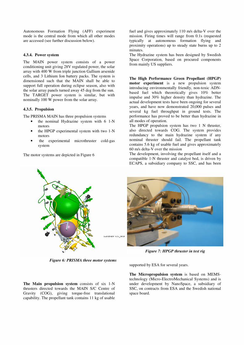
4.3.5. Propulsion
The PRISMA MAIN has three propulsion systems
• the nominal Hydrazine system with 6 1-N
motors
• the HPGP experimental system with two 1-N
motors
• the experimental microthruster cold-gas
system
The motor systems are depicted in Figure 6
The Main propulsion system consists of six 1-N
thrusters directed towards the MAIN S/C Centre of
Gravity (COG), giving torque-free translational
capability. The propellant tank contains 11 kg of usable
fuel and gives approximately 110 m/s delta-V over the
mission. Firing times will range from 0.1s (requested
typically at autonomous formation flying and
proximity operations) up to steady state burns up to 2
minutes.
The Hydrazine system has been designed by Swedish
Space Corporation, based on procured components
from mainly US suppliers.
The High Performance Green Propellant (HPGP)
motor experiment is a new propulsion system
introducing environmentally friendly, non-toxic ADN-
based fuel which theoretically gives 10% better
impulse and 30% higher density than hydrazine. The
actual development tests have been ongoing for several
years, and have now demonstrated 20,000 pulses and
several kg fuel throughput in ground tests. The
performance has proved to be better than hydrazine in
all modes of operation.
The HPGP propulsion system has two 1 N thruster,
also directed towards COG. The system provides
redundancy to the main hydrazine system if any
nominal thruster should fail. The propellant tank
contains 5.6 kg of usable fuel and gives approximately
60 m/s delta-V over the mission
The development, involving the propellant itself and a
compatible 1-N thruster and catalyst bed, is driven by
ECAPS, a subsidiary company to SSC, and has been
supported by ESA for several years.
The Micropropulsion system is based on MEMS-
technology (Micro-ElectroMechanical Systems) and is
under development by NanoSpace, a subsidiary of
SSC, on contracts from ESA and the Swedish national
space board.
Figure 6: PRISMA three motor systems
Figure 7: HPGP thruster in test rig
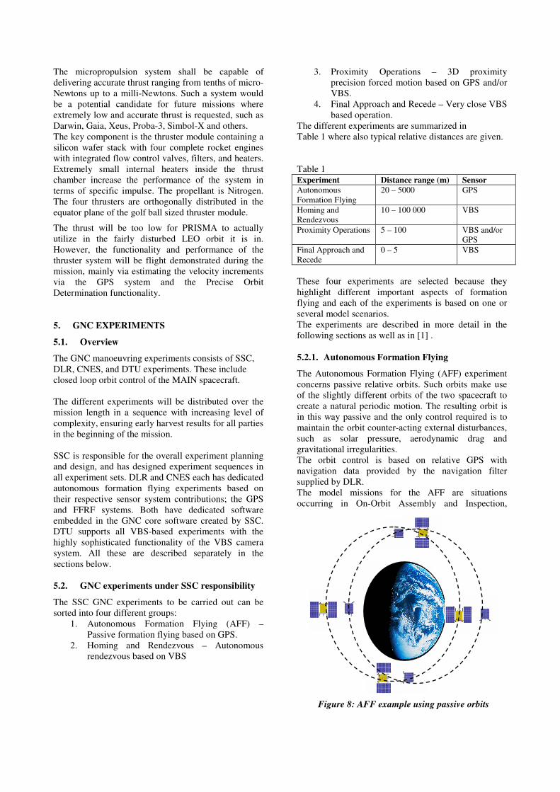
Figure 8: AFF example using passive orbits
The micropropulsion system shall be capable of
delivering accurate thrust ranging from tenths of micro-
Newtons up to a milli-Newtons. Such a system would
be a potential candidate for future missions where
extremely low and accurate thrust is requested, such as
Darwin, Gaia, Xeus, Proba-3, Simbol-X and others.
The key component is the thruster module containing a
silicon wafer stack with four complete rocket engines
with integrated flow control valves, filters, and heaters.
Extremely small internal heaters inside the thrust
chamber increase the performance of the system in
terms of specific impulse. The propellant is Nitrogen.
The four thrusters are orthogonally distributed in the
equator plane of the golf ball sized thruster module.
The thrust will be too low for PRISMA to actually
utilize in the fairly disturbed LEO orbit it is in.
However, the functionality and performance of the
thruster system will be flight demonstrated during the
mission, mainly via estimating the velocity increments
via the GPS system and the Precise Orbit
Determination functionality.
5. GNC EXPERIMENTS
5.1. Overview
The GNC manoeuvring experiments consists of SSC,
DLR, CNES, and DTU experiments. These include
closed loop orbit control of the MAIN spacecraft.
The different experiments will be distributed over the
mission length in a sequence with increasing level of
complexity, ensuring early harvest results for all parties
in the beginning of the mission.
SSC is responsible for the overall experiment planning
and design, and has designed experiment sequences in
all experiment sets. DLR and CNES each has dedicated
autonomous formation flying experiments based on
their respective sensor system contributions; the GPS
and FFRF systems. Both have dedicated software
embedded in the GNC core software created by SSC.
DTU supports all VBS-based experiments with the
highly sophisticated functionality of the VBS camera
system. All these are described separately in the
sections below.
5.2. GNC experiments under SSC responsibility
The SSC GNC experiments to be carried out can be
sorted into four different groups:
1. Autonomous Formation Flying (AFF) –
Passive formation flying based on GPS.
2. Homing and Rendezvous – Autonomous
rendezvous based on VBS
3. Proximity Operations – 3D proximity
precision forced motion based on GPS and/or
VBS.
4. Final Approach and Recede – Very close VBS
based operation.
The different experiments are summarized in
Table 1 where also typical relative distances are given.
Table 1
Experiment Distance range (m) Sensor
Autonomous
Formation Flying
20 – 5000 GPS
Homing and
Rendezvous
10 – 100 000 VBS
Proximity Operations 5 – 100 VBS and/or
GPS
Final Approach and
Recede
0 – 5 VBS
These four experiments are selected because they
highlight different important aspects of formation
flying and each of the experiments is based on one or
several model scenarios.
The experiments are described in more detail in the
following sections as well as in [1] .
5.2.1. Autonomous Formation Flying
The Autonomous Formation Flying (AFF) experiment
concerns passive relative orbits. Such orbits make use
of the slightly different orbits of the two spacecraft to
create a natural periodic motion. The resulting orbit is
in this way passive and the only control required is to
maintain the orbit counter-acting external disturbances,
such as solar pressure, aerodynamic drag and
gravitational irregularities.
The orbit control is based on relative GPS with
navigation data provided by the navigation filter
supplied by DLR.
The model missions for the AFF are situations
occurring in On-Orbit Assembly and Inspection,
passive apertures, and loose formations.
Several different in-plane as well as out-of-plane orbits
will be part of this experiment. The different orbits will
also be applied at different distances.
As shown in Figure 5, the AFF Mode is the central
mode in the mode architecture. The reason is that the
AFF orbit control is considered to be the most robust of
the different experiments. It is also considered to be the
simplest mode in terms of operations. For these
reasons, the mode will be used as a parking mode while
preparing the other experiments. The AFF is illustrated
with Figure 8.
5.2.2. Homing and rendezvous
The Homing and Rendezvous experiment consists of
complete autonomous approach and rendezvous based
on the VBS.
The different phases are - the autonomous location of
the TARGET spacecraft, orbit phasing, intermediate
transfer and in the end, the final approach to the
TARGET spacecraft through a predetermined approach
corridor. All of these steps are designed to be
automatic but with possibilities for commanded escape.
The typical model mission for this experiment is a
Mars Sample Return Mission but servicing in
geosynchronous orbit as well as assembly in escape
orbit are also relevant model scenarios.
The experiment is executed for several cases with Rbar
and Vbar final approach directions.
For each execution of an experiment, the MAIN
spacecraft is placed in a specific relative orbit by
ground command after which the autonomy is enabled.
5.2.3. Proximity operations
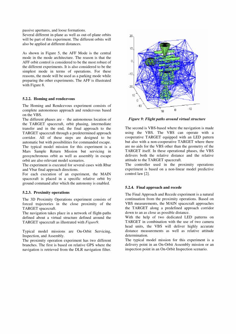
The 3D Proximity Operations experiment consists of
forced trajectories in the close proximity of the
TARGET spacecraft.
The navigation takes place in a network of flight-paths
defined about a virtual structure defined around the
TARGET spacecraft as illustrated with Figure9.
Typical model missions are On-Orbit Servicing,
Inspection, and Assembly.
The proximity operation experiment has two different
branches. The first is based on relative GPS where the
navigation is retrieved from the DLR navigation filter.
The second is VBS-based where the navigation is made
using the VBS. The VBS can operate with a
cooperative TARGET equipped with an LED pattern
but also with a non-cooperative TARGET where there
are no aids for the VBS other than the geometry of the
TARGET itself. In these operational phases, the VBS
delivers both the relative distance and the relative
attitude to the TARGET spacecraft.
The controller used in the proximity operations
experiment is based on a non-linear model predictive
control law [2].
5.2.4. Final approach and recede
The Final Approach and Recede experiment is a natural
continuation from the proximity operations. Based on
VBS measurements, the MAIN spacecraft approaches
the TARGET along a predefined approach corridor
down to an as close as possible distance.
With the help of two dedicated LED patterns on
TARGET in combination with the use of two camera
head units, the VBS will deliver highly accurate
distance measurements as well as relative attitude
determination.
The typical model mission for this experiment is a
delivery point in an On-Orbit Assembly mission or an
inspection point in an On-Orbit Inspection scenario.
Figure 9: Flight paths around virtual structure
5.3. AFF using DLR's GPS-based GNC System
5.3.1. GPS Hardware
The MAIN and the TARGET spacecraft will, for
redundancy purposes, each carry two independent GPS
receivers that are operated in a cold configuration.
Increased flexibility for handling non-zenith pointing
attitudes is provided by two GPS antennas on each
spacecraft, which are selected by an onboard algorithm
for optimum GPS coverage or may, alternatively, be
set by ground command.
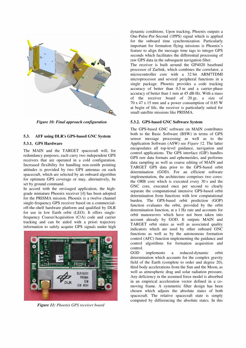
In accord with the envisaged application, the high-
grade miniature Phoenix receiver [4] has been adopted
for the PRISMA mission. Phoenix is a twelve channel
single-frequency GPS receiver based on a commercial-
off-the-shelf hardware platform and qualified by DLR
for use in low Earth orbit (LEO). It offers single-
frequency Coarse/Acquisition (C/A) code and carrier
tracking and can be aided with a priori trajectory
information to safely acquire GPS signals under high
dynamic conditions. Upon tracking, Phoenix outputs a
One-Pulse-Per-Second (1PPS) signal which is applied
for the onboard time synchronization. Particularly
important for formation flying missions is Phoenix’s
feature to align the message time tags to integer GPS
seconds which facilitates the differential processing of
raw GPS data in the subsequent navigation filter.
The receiver is built around the GP4020 baseband
processor of Zarlink, which combines the correlator, a
microcontroller core with a 32 bit ARM7TDMI
microprocessor and several peripheral functions in a
single package. Phoenix provides a code tracking
accuracy of better than 0.5 m and a carrier-phase
accuracy of better than 1 mm at 45 dB-Hz. With a mass
of the receiver board of 20 gr, a size of
70 x 47 x 15 mm and a power consumption of 0.85 W
at begin of life, the receiver is particularly suited for
small satellite missions like PRISMA.
5.3.2. GPS-based GNC Software System
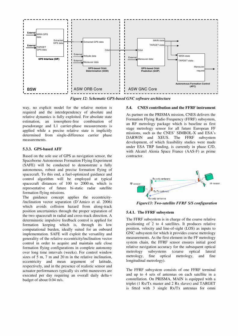
The GPS-based GNC software on MAIN contributes
both to the Basic Software (BSW) in terms of GPS
sensor message processing as well as to the
Application Software (ASW) see Figure 12. The latter
encapsulates all top-level guidance, navigation and
control applications. The GPS interface (GIF) handles
GPS raw data formats and ephemerides, and performs
data sampling as well as coarse editing of MAIN and
TARGET GPS data prior to the GPS-based orbit
determination (GOD). For an efficient software
implementation, the architecture comprises two cores:
the ORB core which is executed every 30 s and the
GNC core, executed once per second to clearly
separate the computational intensive GPS-based orbit
determination from functions with low computational
burden. The GPS-based orbit prediction (GOP)
function evaluates the orbit, provided by the orbit
determination function, at a 1 Hz rate and accounts for
orbit manoeuvres which have not been taken into
account already by GOD. It outputs MAIN and
TARGET orbit states as well as associated quality
indicators which are used by other onboard GNC
functions as well as by the autonomous formation
control (AFC) function implementing the guidance and
control algorithms for formation acquisition and
control.
GOD implements a reduced-dynamic orbit
determination which accounts for the complex gravity
field of the Earth (complete to order and degree 20),
third body accelerations from the Sun and the Moon, as
well as atmospheric drag and solar radiation pressure.
Any deficiency in the assumed force model is absorbed
in an empirical acceleration vector defined in a co-
moving frame. A symmetric filter design has been
chosen which adjusts the absolute states of both
spacecraft. The relative spacecraft state is simply
computed by differencing the absolute states. In this
Figure 10: Final approach configuration
Figure 11: Phoenix GPS receiver board
way, no explicit model for the relative motion is
required and the interdependency of absolute and
relative dynamics is fully exploited. For absolute state
estimation, an ionosphere-free combination of
pseudorange and L1 carrier-phase measurements is
applied while a precise relative state is implicitly
determined from single-difference carrier phase
measurements.
5.3.3. GPS-based AFF
Based on the sole use of GPS as navigation sensor, the
Spaceborne Autonomous Formation Flying Experiment
(SAFE) will be conducted to demonstrate a fully
autonomous, robust and precise formation flying of
spacecraft. To this end, a fuel-optimized guidance and
control algorithm will be employed at typical
spacecraft distances of 100 to 2000 m, which is
representative of future bi-static radar satellite
formation flying missions.
The guidance concept applies the eccentricity-
/inclination vector separation (D’Amico et al. 2006)
which avoids collision hazard from along-track
position uncertainties through the proper separation of
the two spacecraft in radial and cross-track direction. A
deterministic impulsive feedback control is applied for
formation keeping which is, through its low
computational burden, ideally suited for an onboard
implementation. SAFE will exploit the versatility and
generality of the relative eccentricity/inclination vector
control in order to acquire and maintain safe close
formation flying configurations in complete autonomy
over long time intervals (weeks). For control window
sizes of 5 m, 7 m and 20 m in the relative inclination,
eccentricity and mean argument of latitude,
respectively, and in the presence of realistic sensor and
actuator performances typically six orbit maneuvers are
executed per day requiring an overall daily delta-v
budget of about 0.04 m/s.
5.4. CNES contribution and the FFRF instrument
As partner on the PRISMA mission, CNES delivers the
Formation Flying Radio Frequency (FFRF) subsystem,
an RF metrology package which is baseline as first
stage metrology sensor for all future European FF
missions, such as the CNES’ SIMBOL-X and ESA’s
DARWIN and XEUS. The FFRF subsystem
development, of which feasibility studies were made
under ESA TRP funding, is currently in phase C/D,
with Alcatel Alenia Space France (AAS-F) as prime
contractor.
5.4.1. The FFRF subsystem
The FFRF subsystem is in charge of the coarse relative
positioning of 2 to 4 satellites. It produces relative
position, velocity and line-of-sight (LOS) as inputs to
GNC subsystem for which it provides coarse metrology
measurements. As the first element in the FF metrology
system chain, the FFRF sensor ensures initial good
relative navigation accuracy for the subsequent optical
metrology subsystems (coarse optical lateral
metrology, fine optical metrology, and fine
longitudinal metrology).
The FFRF subsystem consists of one FFRF terminal
and up to 4 sets of antennas on each satellite in a
constellation. On PRISMA, MAIN is equipped with a
triplet (1 Rx/Tx master and 2 Rx slaves) and TARGET
is fitted with 3 single Rx/Tx antennas for omni
Figure13: Two-satellite FFRF S/S configuration
MAIN GPS data
TARGET GPS data
Extracted
GPS data
GPS Interface (GIF)
GPS-based Orbit
Determination (GOD)
Extracted GPS data
Attitude data
Maneuver data
Orbit
MAIN state
GPS-based Orbit
Prediction (GOP)
Maneuver data
TARGET state
Autonomous Formation Control
(AFC)
MAIN state
TARGET state
ASW ORB Core
External
External
Orbit
Maneuver
request
External
ASW GNC Core
External
External
BSW
Figure 12: Schematic GPS-based GNC software architecture
directional coverage. The antennas are manufactured
by SAAB Ericsson Space.
The terminal operates by dual frequency in S-band, and
multi-satellite signal exchange is managed by TDMA.
Ranging and angular measurements are extracted from
received signals and are used for computing relative
position (1 cm accuracy), velocity and LOS (1°
accuracy). In addition to providing relative navigation
measurements, the FFRF subsystem also provides time
bias synchronization between the satellite clocks as
well as an inter satellite link (ISL) as auxiliary
functionality (12 kbit/s or 4 kbit/s bitrate).
A detailed description of the FFRF subsystem can be
found in [6].
5.4.2. The FFIORD experiment
FFIORD stands for Formation Flying In-Orbit Ranging
Demonstration, and is the official name of the CNES
experiments within the framework of the PRISMA
mission. The main objectives of this demonstration are
twofold:
♦ Open loop: Validate the FFRF subsystem on
ground and in orbit
♦ Closed loop: Test the control loop and the on-
board algorithms necessary for maintaining 2
satellites autonomously in close formation by
using as input the data from the FFRF sub-system.
The objective of the FFRF sensor validation is to make
the instrument operate in a high variety of conditions,
in order to:
♦ validate the initialization procedure
♦ determinate the measurement limits
♦ verify performances over the whole measurement
domain (range < 15 km v <0.5 m/s, dq/dt < 5°/s)
The closed loop formation flying experiment will be
run by CNES and will put the PRISMA satellites
through a number of formation configurations and
manoeuvres which will be executed autonomously by
the CNES OBSW module during the RF Based
Formation Flying experimental set. The objective is to
put the FFRF sensor and GNC algorithms to the test in
scenarios that are as close as possible to realistic future
FF missions. The experiment will last approximately
17 days, and has been divided into 6 separate
experimental objectives (EO), which will be executed
in parallel or sequentially according to the nature of
each EO:
1. Relative navigation
2. Station-keeping at different distances and offset
positions from the orbit track (VBAR)
3. Translation manoeuvres in plane and cross track
4. Football orbit keeping
5. Collision avoidance (auto. transfer on Football
orbit in 1 or 2 manoeuvres)
6. Deployment phase
A detailed description of the CNES participation on
PRISMA can be found in [7]
5.5. DTU contribution and the VBS system
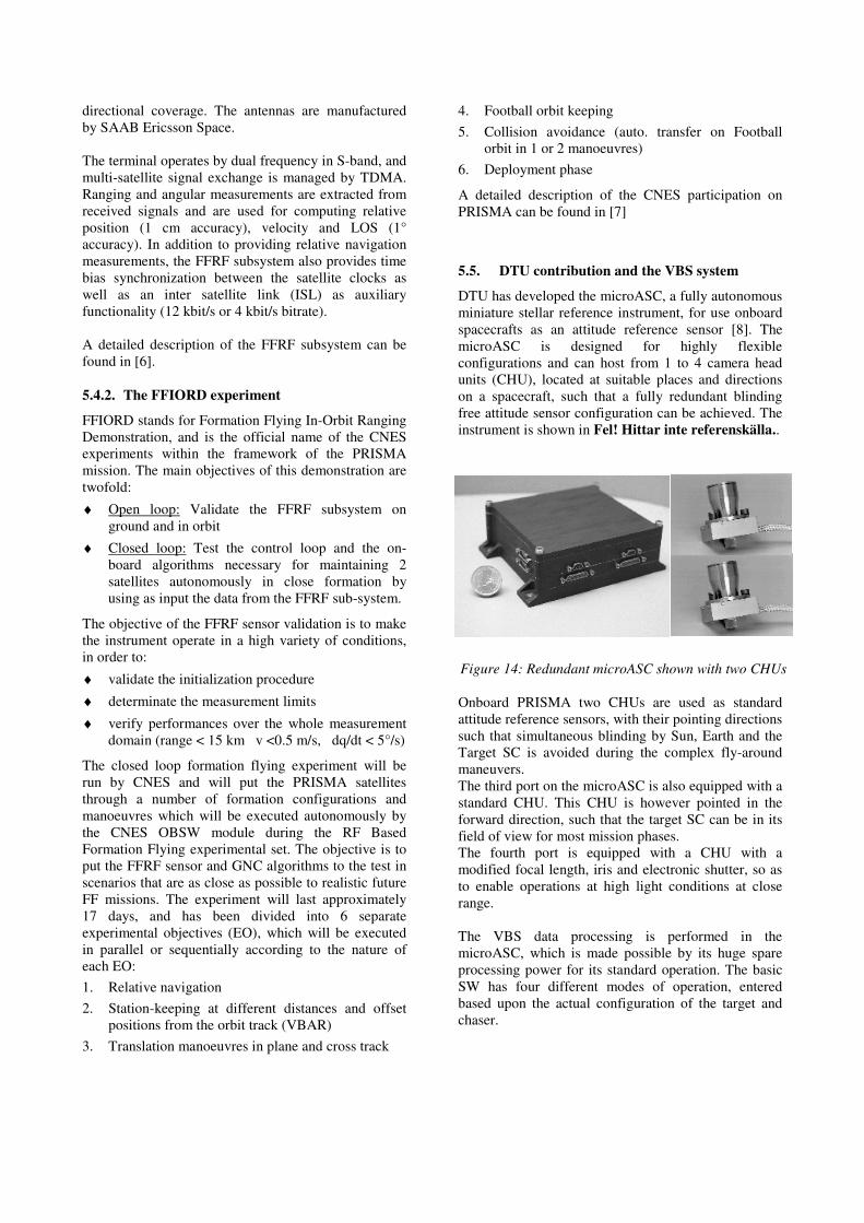
DTU has developed the microASC, a fully autonomous
miniature stellar reference instrument, for use onboard
spacecrafts as an attitude reference sensor [8]. The
microASC is designed for highly flexible
configurations and can host from 1 to 4 camera head
units (CHU), located at suitable places and directions
on a spacecraft, such that a fully redundant blinding
free attitude sensor configuration can be achieved. The
instrument is shown in Fel! Hittar inte referenskälla..
Onboard PRISMA two CHUs are used as standard
attitude reference sensors, with their pointing directions
such that simultaneous blinding by Sun, Earth and the
Target SC is avoided during the complex fly-around
maneuvers.
The third port on the microASC is also equipped with a
standard CHU. This CHU is however pointed in the
forward direction, such that the target SC can be in its
field of view for most mission phases.
The fourth port is equipped with a CHU with a
modified focal length, iris and electronic shutter, so as
to enable operations at high light conditions at close
range.
The VBS data processing is performed in the
microASC, which is made possible by its huge spare
processing power for its standard operation. The basic
SW has four different modes of operation, entered
based upon the actual configuration of the target and
chaser.
Figure 14: Redundant microASC shown with two CHUs
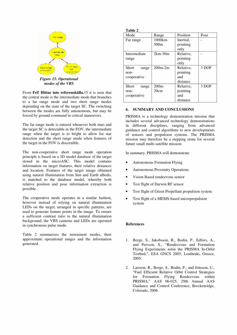
From Fel! Hittar inte referenskälla.15 it is seen that
the central mode is the intermediate mode that branches
to a far range mode and two short range modes
depending on the state of the target SC. The switching
between the modes are fully autonomous, but may be
forced by ground command in critical maneuvers.
The far range mode is entered whenever both stars and
the target SC is detectable in the FOV, the intermediate
range when the target is to bright to allow for star
detection and the short range mode when features of
the target in the FOV is discernible.
The non-cooperative short range mode operation
principle is based on a 3D model database of the target
stored in the microASC. This model contains
information on target features, their relative distances
and location. Features of the target image obtained
using natural illumination from Sun and Earth albedo,
is matched to the database model, whereby both
relative position and pose information extraction is
possible.
The cooperative mode operates in a similar fashion,
however instead of relying on natural illumination
LEDs on the target, arranged in specific patterns, are
used to generate feature points in the image. To ensure
a sufficient contrast ratio to the natural illumination
background, the VBS cameras and LEDs are operated
in synchronous pulse mode.
Table 2 summarizes the instrument modes, their
approximate operational ranges and the information
generated.
Table 2
Mode Range Position Pose
Far range 1000km-
500m
Inertial,
pointing
only
-
Intermediate
range
2km-30m Relative,
pointing
only
-
Short range
non-
cooperative
200m-2m Relative,
pointing
and
distance
3 DOF
Short range
non-
cooperative
200m-
20cm
Relative,
pointing
and
distance
3 DOF
6. SUMMARY AND CONCLUSIONS
PRISMA is a technology demonstration mission that
includes several advanced technology demonstrations
in different disciplines, ranging from advanced
guidance and control algorithms to new developments
of sensors and propulsion systems. The PRISMA
mission may therefore be a stepping stone for several
future small multi-satellite mission.
In summary, PRISMA will demonstrate
• Autonomous Formation Flying
• Autonomous Proximity Operations
• Vision Based rendezvous sensor
• Test flight of Darwin RF sensor
• Test flight of Green Propellant propulsion system
• Test flight of a MEMS-based micropropulsion
system
References
1. Berge, S., Jakobsson, B., Bodin, P., Edfors, A.,
and Persson, S., “Rendezvous and Formation
Flying Experiments witin the PRISMA In-Orbit
Testbed,”, ESA GNCS 2005, Louthraki, Greece,
2005.
2. Larsson, R., Berge, S., Bodin, P., and Jönsson, U.,
“Fuel Efficient Relative Orbit Control Strategies
for Formation Flying Rendezvous within
PRISMA,” AAS 06-025, 29th Annual AAS
Guidance and Control Conference, Breckenridge,
Colorado, 2006.
Figure 15: Operational
modes of the VBS
3. Anflo K., Persson S., Bergman G, Thormälen P,
Hasanof T; Flight Demonstration of an ADN-
Based Propulsion System on the PRISMA
Satellite; 42nd AIAA/AISME/SAE/ASEE Joint
Propulsion Conference & Exhibition, 9-12 July,
Sacramento, Carlifornia
4. Montenbruck O., Nortier B., Mostert S.; A
Miniature GPS Receiver for Precise Orbit
Determination of the SUNSAT2004 Micro-
Satellite; ION National Technical Meeting, 26-28
Jan. 2004, San Diego, California (2004).
5. D’Amico S., Gill E., Montenbruck O.; Relative
Orbit Control Design for the PRISMA Formation
Flying Mission; accepted for AIAA GNC
Conference, August 21-24, 2006, Keystone,
Colorado (2006).
6. Lestarquit. L. et al., “Autonomous Formation
Flying RF Sensor Development for the PRISMA
Mission”, ION GNSS 2006, 25 – 26 Sept. 2006,
Fort Worth, Texas, USA
7. Harr, J. et al., “Formation Flying RF metrology
validation by micro satellites – the CNES
participation on the PRISMA mission”, Small
Satellite Systems and Services Symposium, 25 -
29 Sept. 2006, Chia Laguna, Sardinia, Italy
8. Denver, T, Jørgensen, J.L, Michelsen, R;
Jørgensen, P.S; “MicroASC Star Tracker Generic
Developments”, Small Satellite Systems and
Services Symposium, 25 - 29 Sept. 2006, Chia
Laguna, Sardinia, Italy