Embed Size (px)
Citation preview

PRIVATE AND COMMERCIAL STANDARD OPERATING
PROCEDURES


INTRODUCTION
TAKEOFFS AND LANDINGS
SLOW FLIGHT AND STALLS
GROUND REFERENCE
PERFORMANCE MANEUVERS
MULTI-ENGINE MANEUVERS


STANDARD OPERATING PROCEDURESSOP Rev. DRR-5
TABLE OF CONTENTS
PRIVATE AND COMMERCIAL INTRODUCTION ................................................................................................. 1
MANEUVERS PROCEDURE MANUAL......................................................................................................... 1CLEARING TURNS ....................................................................................................................................... 1MANEUVER SEQUENCE .............................................................................................................................. 2PRE-FLIGHT ACTIONS ................................................................................................................................. 2CARBURETOR HEAT USAGE ..................................................................................................................... 3RUN-UP AREAS KLGU ................................................................................................................................. 4
TAKEOFFS AND LANDINGS ................................................................................................................................ 5
NORMAL TAKEOFF AND LANDING PROCEDURES ................................................................................... 5LANDING PHASE .......................................................................................................................................... 9OTHER TAKEOFF PROCEDURES ............................................................................................................. 16OTHER LANDING PROCEDURES ............................................................................................................. 19GO-AROUND ............................................................................................................................................... 23ABNORMAL LANDING PROCEDURES ...................................................................................................... 26CLIMBOUT, LEVEL OFF, AND CRUISE ...................................................................................................... 29
SLOW FLIGHT AND STALLS .............................................................................................................................. 31
MANEUVERING DURING SLOW FLIGHT .................................................................................................. 31POWER-ON STALL ..................................................................................................................................... 34POWER-OFF STALL .................................................................................................................................... 39
GROUND REFERENCE MANEUVERS .............................................................................................................. 43
TURNS AROUND A POINT ......................................................................................................................... 44RECTANGULAR COURSE .......................................................................................................................... 49S-TURNS ..................................................................................................................................................... 51EIGHTS ON PYLONS (COMMERCIAL ONLY) ............................................................................................ 52
PERFORMANCE MANEUVERS ......................................................................................................................... 55
STEEP TURNS ............................................................................................................................................ 55STEEP SPIRALS (1080° TURNS) ............................................................................................................... 59CHANDELLE ................................................................................................................................................ 61LAZY EIGHTS .............................................................................................................................................. 63
MULTI-ENGINE MANEUVERS ........................................................................................................................... 67
ENGINE FAILURES AND SINGLE ENGINE OPERATIONS ....................................................................... 67VMC DEMO .................................................................................................................................................... 70DRAG DEMO ............................................................................................................................................... 72

STANDARD OPERATING PROCEDURES SOP Rev. DRR-6
STANDARD OPERATING PROCEDURESSOP Rev. DRR-7
Record of Revisions
Revision Release Date
Description
SOP Revision A 07/01/2014 Initial Release
SOP Revision B 9/29/2014 Added Touch-and-go Standard Operating Procedure
SOP Revision C 01/07/2015Added Go-around Standard Operating Procedure, DA 42 Standard Operating Procedures, updated the landing policy and corrected various clerical errors.
SOP Revision D 07/30/2015Moved Steep Turns to the Performance Maneuver section. Added the Multi-Engine Maneuvers section.

STANDARD OPERATING PROCEDURES SOP Rev. DRR-8
Record of Revisions

STANDARD OPERATING PROCEDURESSOP Rev. D1
Introduction
INTRODUCTIONTAKEOFFS AND LANDINGS
SLOW FLIGHT AND STALLSGROUND REFERENCE MANEUVERS
PERFORMANCE MANEUVERS MUILTI-ENGINE MANEUVERS
PRIVATE AND COMMERCIAL INTRODUCTION
MANEUVERS PROCEDURE MANUAL
The objective of this manual is to establish operating procedures for all Private pilot and Commercial pilot maneuvers at USU. Standard procedures for the execution of each training maneuver are detailed herein. These procedures will improve, refine, and develop your piloting skills and provide common guidelines for evaluating all students in the Professional Pilot program. All maneuvers included in this manual will be performed according to these procedures and adhere to the FAA’s most current Practical Testing Standards (PTS). Students will be evaluated according to these procedures on all Stage Checks. This manual contains basic information and standardization information for each maneuver. For a more detailed discussion of each maneuver please refer to the Airplane Flying Handbook FAA publication number: FAA-H-8083-3A. The images in this handbook have been copied from the Airplane Flying Handbook FAA publication number: FAA-H-8083-3A.
NOTE: Any Deviations from SOP’s will be stated and agreed upon by student and CFI prior to flight: such as turns lower than 300’ below TPA.
CLEARING TURNS
Clearing turns are required before initiating any maneuvers. It is expected that a student will perform a clearing turn before each maneuver unless otherwise instructed or allowed by the acting flight instructor. This is a requirement addressing operational safety. A clearing turn will consist of either one 180° turn or two 90° turns. The area should be scanned for any conflicting traffic. A clearing turn is only effective if you are looking outside; don’t get distracted looking inside while performing clearing turns. Unless there is a legitimate reason otherwise, the first turn will be executed to the left. The reason for this is based on the right-of-way rules. If another aircraft is overtaking you from behind it should pass you on the right. If you start your clearing turns to the right you may turn into an aircraft overtaking you. Be cautious of aircraft coming directly at you. In this case, each of you should alter courses to the right and a left clearing turn should be avoided. Make sure there is no aircraft in front of you to the left before initiating your clearing turn. A clearing turn must be executed before each maneuver, unless your flight instructor or the examiner says otherwise.

STANDARD OPERATING PROCEDURES SOP Rev. D2
Introduction
INTR
ODUC
TION
TAKE
OFFS
AND
LAND
INGS
SLOW
FLIG
HT AN
D ST
ALLS
GROU
ND R
EFER
ENCE
MAN
EUVE
RSPE
RFOR
MANC
E MAN
EUVE
RSMU
ILTI-E
NGIN
E MAN
EUVE
RS
MANEUVER SEQUENCE
Each maneuver will be performed in four main steps. The four steps are:
1. Setup2. Execution3. Completion4. Cleanup
PRE-FLIGHT ACTIONS
Visual Inspection
A visual inspection consists of: examination for damage, cracks, delamination, excessive play, load transmission, correct attachment and general condition. In addition, control surfaces should be checked for freedom of movement.
In low ambient temperatures the airplane should be completely cleared of ice, snow and similar accumulations.
Snow, ice, and frost may ONLY be removed by placing the aircraft in a heated hangar and using the approved aircraft squeegee to remove the residual water! DO NOT ATTEMPT TO SCRAPE ICE OR FROST FROM THE AIRCRAFT WITH ANY TOOL WHATSOEVER!
Prior to flight remove such items as tie-downs, control surface gust locks, pitot cover, stall warning cover, chocks, tow bar, etc.
Items to note:
• While checking the G1000 make sure not to touch the displays. If there are fingerprints or marks take care to remove them with approved cleaners found in the Maintenance hangar and by dispatch.• Clean windshields with clean microfiber cloths in a front to back motion only. No circular motions. These micro scratches will allow the water from rain, etc. to roll back off the windscreen. • Verify proper brake pad thickness prior to starting any USU aircraft.• Stay on approved wing walk areas. • Make sure to remove any items brought with you to the aircraft.• Do not pull on the canopy window, use care when opening and closing doors and canopies. • Always secure the aircraft including chocks, gust locks, pitot static covers, and tie-downs.

STANDARD OPERATING PROCEDURESSOP Rev. D3
Introduction
INTRODUCTIONTAKEOFFS AND LANDINGS
SLOW FLIGHT AND STALLSGROUND REFERENCE MANEUVERS
PERFORMANCE MANEUVERS MUILTI-ENGINE MANEUVERS
Aircraft Starting
Do not overheat the starter motor. Do not operate the starter motor for more than 10 seconds. After operating the starter motor, let it cool off for 20 seconds. After 6 attempts to start the engine, allow the starter to cool off for half an hour.
NEVER engage the starter with the propeller still in motion.
During winter operations,the use of an external pre-heater and external power source is recommended whenever possible, particularly at ambient temperatures below 0 °C (32 °F). Pre-heating will reduce wear and abuse to the engine and electrical system. Pre-heating liquefies the oil trapped in the oil cooler, which can be congealed in extremely cold temperatures. If pre-heating or external power is required a USU Mechanic or Flight Instructor must be present to help. After a warm-up period of approximately 2 to 5 minutes (depending on the ambient temperature) at 1500 RPM, the engine is ready for take-off if it accelerates smoothly and the oil pressure is normal and steady.
CARBURETOR HEAT USAGE
Carburetor heat should be used as deemed necessary by the pilot to avoid carburetor ice formation! It should be used anytime carburetor icing is suspected or anytime the potential for carburetor ice is present, including anytime visible moisture is present.
As standard USU procedure:
Carburetor heat will be ON for Descent and may be turned OFF upon leveling-off.Carburetor heat will be ON during the downwind leg and turned OFF with flap application on Base.Carburetor heat will be turned OFF 200 feet above MDA or DH on an instrument approach and then used as necessary after arriving at MDA or DH.
CAUTION: Carburetor heat should be used during prolonged glides with the throttle closed because of rapid engine cooling. The aircraft engine may not respond with rapid throttle application; therefore, the throttle should be fully opened every thirty seconds to clear the engine

STANDARD OPERATING PROCEDURES SOP Rev. D4
Introduction
INTR
ODUC
TION
TAKE
OFFS
AND
LAND
INGS
SLOW
FLIG
HT AN
D ST
ALLS
GROU
ND R
EFER
ENCE
MAN
EUVE
RSPE
RFOR
MANC
E MAN
EUVE
RSMU
ILTI-E
NGIN
E MAN
EUVE
RS
RUN-UP AREAS KLGU
Engine run-up is to be performed in areas designated for that operation. See the diagram below for operations at KLGU. Consult publications or local procedures for operations at other locations. Position the aircraft as nearly into the wind as practicable while not allowing propeller blast to throw debris at other aircraft or structures.
Run-up Area RW 17
Run-up AreaRW 35/28
Run-up Area RW 17/10

STANDARD OPERATING PROCEDURESSOP Rev. D5
Takeoffs and Landings
INTRODUCTIONTAKEOFFS AND LANDINGS
SLOW FLIGHT AND STALLSGROUND REFERENCE MANEUVERS
PERFORMANCE MANEUVERSMULTI-ENGINE MANEUVERS
TAKEOFFS AND LANDINGS
NORMAL TAKEOFF AND LANDING PROCEDURES
Before taxiing, verify taxi clearances (if in tower operations) or taxi using extreme caution to run-up areas and then to runway. It is required for USU pilots to have an airport diagram out during all taxiing. Electronic Flight Bags (EFB), digital readers such as iPAD’s or other electronic devices, may be used for this. Be certain to precisely follow assigned clearances and prescribed operations, (e.g. “LINE UP AND WAIT” or “CLEARED FOR TAKEOFF.” “TAKING RUNWAY _## _ FOR DEPARTURE.”) Confirm that approach and departure sectors are clear, and that the runway itself is clear prior to commencing the takeoff. Final is clear by the callout, “Final is clear.” All callouts are expected on dual and solo flights.
Takeoff Roll and Acceleration
After verifying runway environment is clear, confirm the appropriate runway is being used. Runway and heading are confirmed by comparing the reading on the HSI or Heading Indicator to the expected runway heading of the assigned runway. While lining up on the center line of the runway, use a ground reference straight down the runway to help you with proper alignment of the aircraft during ground roll and takeoff. Verify center line with magnetic compass readings approximately the same heading as the runway itself. The standard call is, “Runway heading ### confirmed.” Before applying power for takeoff confirm the runway is clear by the callout, “Runway is clear.”
Smoothly apply full power, to reduce the yawing tendencies inherent with the left turning tendencies of the aircraft. Monitor the engine instruments and airspeed indicator. Abort the takeoff if any abnormal readings in engine indications or airspeed are noticed; otherwise announce: “POWER CHECKED,” or “POWER GREATER THAN 2200 RPM,” and “AIRSPEED ALIVE.”
Maintain directional control with the rudder without using the brakes. Adding brakes during the takeoff roll will increase your takeoff distance and could cause excessively hot brakes or even blown tires. Announce at VR:
DA 40-F “59 KTS, ROTATE” PA28R-200 “65 MPH. ROTATE” DA 42 “70 or 72 KTS, ROTATE” (based on weight)
NOTE: A rejected takeoff is ALWAYS an option. If the aircraft is not performing as expected, terminate the flight and trouble shoot the problem on the ground. Rejected takeoff includes: Closing the throttle, maintaining center line, applying brakes to maintain center line (do not lock up the brakes or apply asymmetrically) and stopping on the remaining runway and taxi clear if possible.

STANDARD OPERATING PROCEDURES SOP Rev. D6
Takeoffs and Landings
INTR
ODUC
TION
TAKE
OFFS
AND
LAND
INGS
SLOW
FLIG
HT AN
D ST
ALLS
GROU
ND R
EFER
ENCE
MAN
EUVE
RSPE
RFOR
MANC
E MAN
EUVE
RSMU
LTI-E
NGIN
E MAN
EUVE
RS
Rotation
At VR smoothly and gently pull back on the flight controls, keep wings level and compensate for the P-factor while accelerating to Vy. Vy varies depending upon the aircraft configuration and/or its weight. Airspeeds for Vy are listed below:
DA 40-F 1874 Lbs. . . . . . . . . . . 54 KIAS 2205 Lbs. . . . . . . . . . . 60 KIAS 2535 Lbs. . . . . . . . . . . 66 KIAS After rotate establish a pitch of +8°
PA28R-200 (landing gear down) . . . 95 MPH (landing gear up) . . . . . 100 MPH Establish a pitch between ~5 - 7°
DA 42 (landing gear down to 500’ AGL) . . . . . . . .77-79 KIAS (based on weight) (landing gear up above 500’ AGL) . . . . . .82 KIAS (Vyse) Establish a pitch of ~+12°
Do not force the aircraft off the ground; let it fly off the runway. Forcing the aircraft off the ground can place the aircraft in a situation where a stall is inherent once out of ground effect. A low level stall will likely be catastrophic.
Initial climb out
At 500 feet AGL, turn off the fuel pump and lower the nose of the aircraft slightly (2° should be sufficient) to facilitate speed increase to secondary climb speed for climb out. Unless there are abnormal circumstances, do not turn below Minimum Safe Altitude (500 feet AGL). Trim the aircraft as necessary. This will allow you to be more precise, and focus on the flying environment.
DA40-F- Verify Fuel Pump Off and T/O Flaps Up, Secondary Climb Speed 73 KIAS
PA28R-200- Verify Fuel Pump off, Landing Gear Up, and Flaps Up. Secondary Climb 100-105 MPH
DA 42 - Reduce Power to 90%, Landing Gear Up, and Flaps Up, Secondary Climb at 82 KIAS (Vyse)
Turn Crosswind leg no lower than 300 feet below traffic pattern altitude.

STANDARD OPERATING PROCEDURESSOP Rev. D7
Takeoffs and Landings
INTRODUCTIONTAKEOFFS AND LANDINGS
SLOW FLIGHT AND STALLSGROUND REFERENCE MANEUVERS
PERFORMANCE MANEUVERSMULTI-ENGINE MANEUVERS
Normal Pattern
The above picture is a standard left hand pattern. All patterns are controlled by ATC as to direction and how to enter. In lieu of ATC the AIM provides the above pattern to increase safety. USU will follow the AIM when not under ATC control. Verify the direction of the traffic pattern at the airport of intended use by way of A/FD. Traffic patterns are selected by wind speed and direction. USU considers wind below 5 knots to be calm winds.
All non-ATC patterns consist of legs:
Departure Leg: is the leg over the runway center line and following an extended center line. This takes the aircraft on to number 4. This can be turned to Crosswind leg, or carried out as a true departure either straight out or on a 45° exit after reaching the minimum safe altitude of 500’ AGL continuing in the climb to an appropriate altitude for cruise or maneuvers. Departure leg is sometimes called UPWIND leg but this is inconsistent with AIM.
Crosswind Leg: Is the flight path at a right angle to the landing runway at the takeoff end. It is opposite the Base Leg. A turn from the departure leg onto the crosswind leg should not be attempted unless the aircraft is within 300’ of the Traffic Pattern Altitude (TPA) (e.g. Logan Cache airport has a 1000’ AGL TPA making crosswind turn at 700’ AGL (5157 MSL for KLGU)).
Downwind Leg: Is parallel to the landing runway and in the opposite direction (number

STANDARD OPERATING PROCEDURES SOP Rev. D8
Takeoffs and Landings
INTR
ODUC
TION
TAKE
OFFS
AND
LAND
INGS
SLOW
FLIG
HT AN
D ST
ALLS
GROU
ND R
EFER
ENCE
MAN
EUVE
RSPE
RFOR
MANC
E MAN
EUVE
RSMU
LTI-E
NGIN
E MAN
EUVE
RS
1). Landings are made into the wind therefore the wind will be coming from behind the aircraft on this leg. The downwind Leg is flown at the TPA for the airport or intended landing. If doing pattern work, complete the approach/descent checklists, during the downwind leg. If entering the downwind leg on a 45 complete the descent approach checklist prior to entering the downwind leg. Visually scan for traffic, and configure the aircraft for the landing segment. Be aware that aircraft attempting to enter the pattern SHOULD be aiming for mid-field. Be aware of this as you turn downwind and scan both above and below TPA. Descent/Approach checklist should be completed during the downwind leg. Be vigilant for other aircraft. Be sure to account for a faster groundspeed in this segment if winds are present. All configuration changes should be made in a wings level attitude.
Abeam the touchdown point we will decrease power, add flaps as needed, and begin a descent to approximately 300’ below TPA. See Aircraft- set up below.
Base Leg: Is the flight path at right angles to the landing runway off the approach end of the runway and extending from the downwind leg. It is primarily used for the loss of altitude, USU pilots will look to lose around another 300’ on base leg, and maneuvering for final leg. At the end of the Base leg we should be around 4-500’ AGL and turning to join the extended center line for Final. Most if not all configuration changes should be made by this point. Check for traffic on both final and on the runway.
Final Leg: is a flight path in the direction of landing along the extended runway center line. As stated we should be letting down from 4-500’ AGL along a consistent glide path to the runway in a STABILIZED APPROACH.
DA 40F- o Abeam: ~1600 RPM, 90 KIAS, -2° pitch, Fuel Pump on, Carburetor Heat on, First notch of flaps. o Base: ~1400 RPM, 80 KIAS, -3° pitch, Second notch of flaps, Carburetor heat off. o Final: ~1400 RPM, 75 KIAS, -4° Pitch, Landing configuration, and aligned with center line.
PA28R-200- o Abeam: ~17” Manifold Pressure, Propeller full forward, 100 MPH, Fuel pump on, Landing Gear verified down and locked (3 greens) by verbally stating “Gear down three green”, First notch of flaps. o Base: ~15’ M.P., Props full forward, Gear verified down and locked (3 greens) by verbally stating “Gear down three green”, 95 MPH, second notch of flaps. o Final: ~16’ M.P., Props full forward, Gear verified down and locked (3 greens) by verbally stating “Gear down three green”, 85 MPH, Third notch of flaps.

STANDARD OPERATING PROCEDURESSOP Rev. D9
Takeoffs and Landings
INTRODUCTIONTAKEOFFS AND LANDINGS
SLOW FLIGHT AND STALLSGROUND REFERENCE MANEUVERS
PERFORMANCE MANEUVERSMULTI-ENGINE MANEUVERS
DA 42- o Abeam: ~30% load, Gear verified down and locked (3 greens) by verbally stating “Gear down three green”, First notch of flaps. o Base: ~30% load, Gear verified down and locked (3 greens) by verbally stating “Gear down three green”, 90 KIAS, second notch of flaps. o Final: ~30% load, Gear verified down and locked (3 greens) by verbally stating “Gear down three green”, 82 KIAS, and aligned with center line.
Upwind Leg: Is a flight path parallel to the landing runway into the wind, and on the opposite side of the traffic pattern from downwind. To get onto the Upwind you must side step the runway. Example Left hand pattern, aircraft turns final, but needs to “go-around” due to other traffic taking the runway. The aircraft on final will side step to the right (away from downwind traffic) and commence a climb. Careful of the other traffic departing under you. The best option might be to leave the pattern and re-enter on a 45° Entry.
45° Entry: is the prescribed way to enter a traffic pattern. This is an entry that intersects the downwind leg of the traffic pattern. The midfield point where the 45 meets the downwind leg segment. Joining the downwind can be difficult, if it is too busy turn away from the pattern and attempt another re-entry from the 45. Traffic already established in the pattern has the right of way. So if timing/spacing aren’t sufficient follow the prescribed re-entry on the 45. ADDITIONAL entries could include-Straight-in: where aircraft is attempting to join an extended Final. Again aircraft in the pattern have the right of way. Careful if there is traffic straight in but in the opposite direction of the departing runway. All efforts to avoid this type of set up should be used. Some aircraft will call joining a base for the active runway. This is not a conventional entry, and should not be used by USU pilots unless directed by ATC.
LANDING PHASE
The landing phase is the most difficult phase. There are multiple factors which require your attention. Any deviations must be corrected immediately allowing for successful landings. Pay attention to the aircraft “deck angle,” descent angle, airspeed, and float as you learn how to land. No more then three consecutive landing shall be practiced at any one time. A student or a student and an instructor may begin a flight lesson with three consecutive landings depart the traffic pattern and return for three more landings.
Normal Landings
On downwind, complete the approved before landing checklist. Begin descent and reduce power when you are properly configured and you are abeam your selected touchdown point. On base extend flaps as needed. On final align airplane with center line and make final flap selection; usually full flaps unless air is turbulent or gusty. Adjust power as necessary to maintain VTGT on final and trim controls.

STANDARD OPERATING PROCEDURES SOP Rev. D10
Takeoffs and Landings
INTR
ODUC
TION
TAKE
OFFS
AND
LAND
INGS
SLOW
FLIG
HT AN
D ST
ALLS
GROU
ND R
EFER
ENCE
MAN
EUVE
RSPE
RFOR
MANC
E MAN
EUVE
RSMU
LTI-E
NGIN
E MAN
EUVE
RS
VTGT:
DA40-F- 75 KTS PA28R-200- 90 MPH (verify gear down, and flaps down) DA42- 82 KTS (verify gear down, and flaps down)
Obstructions and other hazards which should be considered
Consider winds, check ATIS/AWOS or wind sock on airport. Be aware in a strong headwind: fly a closer base leg to the end of the runway; to fly the same glide path you would use power and a lower rate of descent on final. A strong, gusty, turbulent wind: increase airspeed on final approach for more positive control of airplane; gust factor should be adjusted for (normal approach speed plus ½ the gust factor), gust factor is difference between steady state wind and max gust. Note if using a higher approach speed you may not need to use all the flaps
Be aware of traffic, both in the air and on the ground.
Select a touchdown point that is beyond the runway’s landing threshold but well within the first one-third of the runway. After selecting touchdown point, select your aiming points; this will be the point at the end of your selected glide path and will be short of your touchdown point.
Stabilized Approach
A stabilized approach means that the airplane is in a position where minimum input of all controls will result in a safe landing. This method is used by the airlines, and comes with experience. Set up is the key factor. By constantly being at the same altitude, distance, power settings, etc., you will be able to better judge your approach to landing.
Excessive control input at any juncture could be an indication of improper planning. The objective of a good final approach is to descend at an angle and airspeed that will permit your airplane to reach the desired touchdown point at an airspeed that will result in a minimal float before touchdown
Fundamental keys are:
1. Correlation of pitch and power demands that any change to one element in the approach must be compensated for by modification in the other.2. Power should be adjusted as necessary to control the airspeed, and the pitch attitude adjusted simultaneously to control the descent angle.

STANDARD OPERATING PROCEDURESSOP Rev. D11
Takeoffs and Landings
INTRODUCTIONTAKEOFFS AND LANDINGS
SLOW FLIGHT AND STALLSGROUND REFERENCE MANEUVERS
PERFORMANCE MANEUVERSMULTI-ENGINE MANEUVERS
When established on final, use pitch of either a glide path or visual path to fly your airplane to the aiming point. When you are on a constant glide path the aiming point has no apparent movement in your windshield; no pitch correction is needed.
Anytime we are within 500’ AGL and any of the following occur, you are NOT stabilized:
1. Aircraft is not aligned with runway.2. Excessive or too low airspeed.3. Judgment that aircraft will float, or sink to rapidly.4. Descent rates exceeding 1000 FPM.5. Small corrections will not “correct” the landing phase.
We are not looking to salvage any landing. Time and talent are best spent on proceeding onto a go-around and setting up again. Going around is always the best option. By repeating the go-around you learn the fundamentals from judging when to turn final and when it is unsafe to continue and how to transition back out of landing setup to a climb setup.
Coordination of Flight Controls
Flight controls should always be used in a proper and coordinated manner (turning or slipping), when turning use no more than 30 degrees of bank angle; the steeper the bank angle the more load factor on the airplane and the greater the load factor, the greater the stall speed. Remember the most dangerous situation is turning base to final and pilot attempts to increase the rate of turn by use of the rudder only, this is a situation which could lead to a stall, be vigilant on your slips to a landing that your airspeed remains at or above the approach speed. A precise ground track will give you the extended center line of the runway when rolling out of your base turn; if there is a crosswind the nose of the airplane might not be align with center line but make sure the ground track is aligned.
Visual cues as to descent angles will help as you learn to fly. Remember that landing at different airports with narrower or wider runways may skew your perception of the appropriate flight path.

STANDARD OPERATING PROCEDURES SOP Rev. D12
Takeoffs and Landings
INTR
ODUC
TION
TAKE
OFFS
AND
LAND
INGS
SLOW
FLIG
HT AN
D ST
ALLS
GROU
ND R
EFER
ENCE
MAN
EUVE
RSPE
RFOR
MANC
E MAN
EUVE
RSMU
LTI-E
NGIN
E MAN
EUVE
RS

STANDARD OPERATING PROCEDURESSOP Rev. D13
Takeoffs and Landings
INTRODUCTIONTAKEOFFS AND LANDINGS
SLOW FLIGHT AND STALLSGROUND REFERENCE MANEUVERS
PERFORMANCE MANEUVERSMULTI-ENGINE MANEUVERS
Wind Shear and Wake Turbulence
Wind shear and wake turbulence avoidance is the PIC’s responsibility. Tower might advise you of possible wake turbulence, but they are not required to. Keep in mind if landing within 5 minutes following a large aircraft, keep your flight path above that of the larger aircraft and land at a point beyond the larger aircraft’s touchdown point.
Wind shear can happen at any altitude in any direction; if wind shear is expected fly at a higher airspeed which will increase controllability. Wind shear dissipates within 15 minutes. If you suspect wind shear, stay away from the location, until 20 minutes have passed.
Round out/Flare
Get in the habit of keeping one hand on the throttle control throughout the approach and landing; this will allow immediate action if an unexpected hazardous situation occurs.
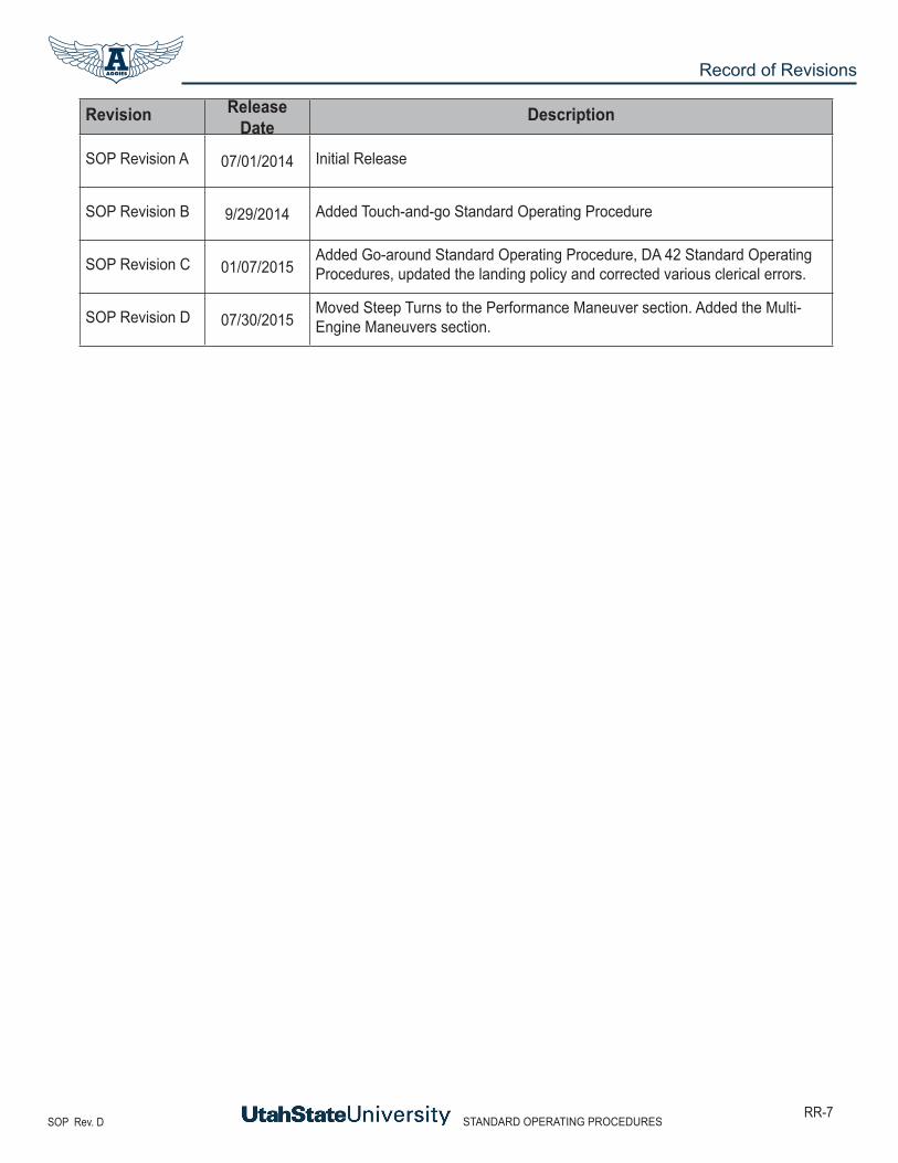
There is about a 300 foot difference in the PA28R-200 and about a 500 foot difference in the DA40 and DA42 between the point/location you are aiming for and the point the aircraft will touchdown and settle on the runway. These numbers are based on coming in at proscribed airspeeds, in the DA40 take weight into account. The aiming point is the point where, if the plane did not round out, it would touch the ground. The touchdown point is the point where the main wheels touchdown after the round out.
STANDARD OPERATING PROCEDURES SOP Rev. D14
Takeoffs and Landings
INTR
ODUC
TION
TAKE
OFFS
AND
LAND
INGS
SLOW
FLIG
HT AN
D ST
ALLS
GROU
ND R
EFER
ENCE
MAN
EUVE
RSPE
RFOR
MANC
E MAN
EUVE
RSMU
LTI-E
NGIN
E MAN
EUVE
RS
As you approach the aiming point, begin to round out by slowly reducing power and slowly increasing back pressure. The main wheels should touch the ground just above stall speed.
Angle of attack will be increased to generate more lift at slower airspeeds, to maintain the near zero descent rate.

STANDARD OPERATING PROCEDURESSOP Rev. D15
Takeoffs and Landings
INTRODUCTIONTAKEOFFS AND LANDINGS
SLOW FLIGHT AND STALLSGROUND REFERENCE MANEUVERS
PERFORMANCE MANEUVERSMULTI-ENGINE MANEUVERS
Different flap settings will affect the landing. The use of differing amount of flaps are needed in different conditions such as if winds are stronger use less flaps.

STANDARD OPERATING PROCEDURES SOP Rev. D16
Takeoffs and Landings
INTR
ODUC
TION
TAKE
OFFS
AND
LAND
INGS
SLOW
FLIG
HT AN
D ST
ALLS
GROU
ND R
EFER
ENCE
MAN
EUVE
RSPE
RFOR
MANC
E MAN
EUVE
RSMU
LTI-E
NGIN
E MAN
EUVE
RS
Remember, the less degree of flaps you use the longer the glide will be. After the main wheels touch the ground, ease in the back pressure. Do not force the nose wheel onto the ground as this could cause wheel barrowing. Use brakes only as needed. Do not force the plane to make the first exit to save some time. It will take a lot longer if a tire blows out!
OTHER TAKEOFF PROCEDURES
Crosswind Takeoff
Crosswinds will tend to yaw the nose of the aircraft into the wind. This is called “weathervaning.” To compensate for this tendency, apply downwind rudder pressure. Crosswind aileron controls included placing the upwind aileron in the up position to aerodynamically push that wing down thus allowing the main gear to maintain contact with the ground. As speed increases controllability of the aircraft increases, therefore ailerons become more effective, a control reduction may be necessary to maintain wings level position while rotating. See the Airplane Flying Handbook Chapter 5 for more information. (Images 5-3 and 5-4 From AFH). Remember A-E-R for effectiveness, Ailerons, Elevator, Rudder.
NOTE: It is clearly not recommended to practice this maneuver while strong crosswinds are present. Remember your Maximum Crosswind Component, found in AFM/POH. DA40 is 20 KIAS and PA28R200 is 20 MPH.

STANDARD OPERATING PROCEDURESSOP Rev. D17
Takeoffs and Landings
INTRODUCTIONTAKEOFFS AND LANDINGS
SLOW FLIGHT AND STALLSGROUND REFERENCE MANEUVERS
PERFORMANCE MANEUVERSMULTI-ENGINE MANEUVERS
Remember to maintain Vy +10/-5 during the climbout.
Rotating the DA40 with a slightly higher airspeed (61 KIAS) will give more control during crosswind takeoffs.
Diamond DA40 and DA42 have a maximum wind for takeoff (26 knots), maximum wind for landing (35 knots), and maximum wind for taxi operations (35 knots) and a maximum crosswind of (20 knots).
When wind velocity excited those limitations the USU fleet is grounded (see Operations Handbook).
Soft-field Takeoff and Climb
Soft-field takeoffs are practiced to simulate a non-paved, soft or contaminated runways (grass, snow etc.) Before taxiing onto the runway, the stick or yoke should be in the full aft position. This minimizes the weight on the nose wheel. Stopping is not recommended since the main tires could sink into the ‘soft’ field. Power is applied smoothly and evenly to avoid Foreign Object and Debris (FOD damage) or sudden yawing movement to the left. As the nose lifts off the ground release back pressure slightly to avoid striking the tail or becoming airborne to soon and resettling back on the runway. Due to ground effect, the aircraft will become airborne below a safe airspeed. Stay in ground effect by remaining one-half the length of the wingspan, and accelerate to VY while in ground effect.

STANDARD OPERATING PROCEDURES SOP Rev. D18
Takeoffs and Landings
INTR
ODUC
TION
TAKE
OFFS
AND
LAND
INGS
SLOW
FLIG
HT AN
D ST
ALLS
GROU
ND R
EFER
ENCE
MAN
EUVE
RSPE
RFOR
MANC
E MAN
EUVE
RSMU
LTI-E
NGIN
E MAN
EUVE
RS
Accelerate and climb at:
DA40-F- 66 KTS PA28R-200- 85 MPH (Obstacles) 95 MPH (No Obstacles) DA42- Not Applicable
At 500’ AGL you can retract the flaps, perform the Above 500 Feet AGL Checklist. Continue climbing normally and accelerate to:
DA40-F- 73 KTS PA28R-200- 100 MPH (verify gear up, and flaps up) DA42- Not Applicable
Short-Field Takeoff and Climb
Short-field Takeoffs are practiced to simulate a takeoff from a shorter runway with an obstacle in the departure path. Maximum utilization of the runway is mandatory, taxi onto the runway with minimal loss of runway. Brakes and proper flight coordination are required, especially in crosswinds.
Set Flaps to T/O (DA40-F) or to 25° Second notch (PA28R-200). For the DA42 flaps stay up.
After aligning the aircraft with the runway center line, smoothly apply maximum power while holding the brakes. Check the engine gauges prior to releasing the brakes. As the aircraft gains speed avoid premature lift off until rotate speed is achieved. The rotation should be smooth and deliberate. Premature lift off will cause an excessive amount of drag consequently lengthening the require runway distance.
Rotate at:
DA40-F- 59 KTS lower the nose once airborne and accelerate to 66 KTS this is the best rate of climb speed. Once a simulated 50’ obstacle is cleared continue in climb to 500’ then continue normal climb at 73 KTS.
PA28R-200- 65 MPH lower the nose once airborne and accelerate to 85 MPH tap brakes, retract gear and climb at 96 MPH until the obstacle is clear. Pitch to 100 MPH above the 50’ obstacle. Remove one notch of flaps.
DA42- 70-72 KTS accelerate to 77-79 KTS is the best rate of climb speed based on your weight. Once a simulated 50’ obstacle is cleared continue in climb to 500’ then continue normal climb at 82 KTS.
You may be given a simulated 50 foot obstacle to clear at a certain location on the runway, if such is the case, announce “Obstacle Clear” at or above 50 feet AGL.
Perform the “Above 500 Feet AGL” checklist.

STANDARD OPERATING PROCEDURESSOP Rev. D19
Takeoffs and Landings
INTRODUCTIONTAKEOFFS AND LANDINGS
SLOW FLIGHT AND STALLSGROUND REFERENCE MANEUVERS
PERFORMANCE MANEUVERSMULTI-ENGINE MANEUVERS
Due to the slower airspeed at takeoff and a higher nose attitude, the yaw of the aircraft will tend to increase requiring more right rudder compensation. This takeoff is only slightly different from a normal one with the same directional control and crosswind procedure.
It is not recommended to practice this maneuver while strong crosswinds are present.
OTHER LANDING PROCEDURES
Crosswind Approach Procedures
On crosswind approaches, there are two methods of maintaining the proper ground track on final approach: crab and side-slip (wing low) method
1. Crab method: • establish a heading toward the wind with the wings level so that your airplane’s ground track remains aligned with center line; • maintain that heading until just prior to touchdown, when the longitudinal axis of the airplane must be quickly aligned with the runway; • crabbing is best used on a long final approach and is most comfortable for passengers

STANDARD OPERATING PROCEDURES SOP Rev. D20
Takeoffs and Landings
INTR
ODUC
TION
TAKE
OFFS
AND
LAND
INGS
SLOW
FLIG
HT AN
D ST
ALLS
GROU
ND R
EFER
ENCE
MAN
EUVE
RSPE
RFOR
MANC
E MAN
EUVE
RSMU
LTI-E
NGIN
E MAN
EUVE
RS
2. Side-slip (wing low) method: • recommended in most cases since it will compensate for a crosswind at any angle and will enable you to simultaneously keep the airplane’s ground track and longitudinal axis aligned with the center line throughout the approach • align airplane’s heading with the center line and note the rate and direction of drift • promptly apply drift correction by lowering the upwind wing (amount depends on rate of drift) • when you lower that wing, the airplane will tend to turn in that direction so you will need to apply sufficient opposite rudder pressure to prevent the turn and keep the airplane’s longitudinal axis aligned with the runway • drift controlled with aileron; heading controlled with rudder • in a very strong crosswind the required bank may be so steep that full opposite rudder will not prevent a turn; the wind is too strong to land safely on that particular runway with those conditions
Crosswind Landings
While turning final, crab the nose into the wind to maintain a straight ground track. Around 50-100 feet above the ground change the aircraft’s attitude towards the wing low method. Apply opposite rudder to the crab. At the same time lower the wing into to wind. This will keep the aircraft on a constant ground track and aligned with the runway center line. Maintain this attitude throughout the flare and the touchdown. Landing should be made with the “upwind” main wheel first. After all wheels are on the ground, apply the aileron controls as per crosswind taxi procedures.
Remember the effectiveness of control surfaces is as follows: Ailerons, Elevator, and Rudder. It is very important to make the appropriate aileron deflections when taxiing with high or gusty winds.

STANDARD OPERATING PROCEDURESSOP Rev. D21
Takeoffs and Landings
INTRODUCTIONTAKEOFFS AND LANDINGS
SLOW FLIGHT AND STALLSGROUND REFERENCE MANEUVERS
PERFORMANCE MANEUVERSMULTI-ENGINE MANEUVERS

STANDARD OPERATING PROCEDURES SOP Rev. D22
Takeoffs and Landings
INTR
ODUC
TION
TAKE
OFFS
AND
LAND
INGS
SLOW
FLIG
HT AN
D ST
ALLS
GROU
ND R
EFER
ENCE
MAN
EUVE
RSPE
RFOR
MANC
E MAN
EUVE
RSMU
LTI-E
NGIN
E MAN
EUVE
RS
Soft-Field Landings
Soft field landings are flown the same as normal landings, except you will close the throttle completely and then add some power while in ground effect (approximately one-half the length of the wing span) and decelerating to the reference speed for your aircraft. The landing should be made within the first third of the runway as per the recommendations of the AIM.
DA40-F- 70 KTS PA28R-200- 90 MPH DA42- Not Applicable
Try to touchdown as softly as possible and at the lowest possible safe airspeed. The nose wheel should stay airborne as long as possible to avoid becoming stuck in the soft runway surface. Be aware that you don’t allow the nose wheel to fall out of the sky either. This is done by controlling the elevator pressure. The nose wheel should slowly come down as normal and not bounce as it does. Brakes should be used with caution, and no adjustments to aircraft configuration should be made to the flaps until clear of the runway.
Short-Field Landings
Short field landings are flown with flaps at maximum on base leg:
DA40-F- LDG PA28R-200- Flaps 40° Third Notch DA42- LDG
This will give you the steepest approach without increasing your airspeed. Fly a normal pattern and establish a stabilized approach at V(ref) speed. In certain cases a non-stabilized approach may be required, and flown as a visual “step down,” no USU approved airports will require this type of approach. In order to land at an actual short field lower the flaps at least 500 feet above touchdown elevation. Remember we are close to the area of reverse command, where pitch controls airspeed, and power controls altitude. Be cautious of losing to much of your airspeed on approach.
Approach Speeds or V(ref):
DA40-F- 66 KTS PA28R-200- 85 MPH DA42- 76 KTS
Set the aiming point in front of the touchdown point, and be certain your descent path will clear the obstacle. Once the obstacle is cleared decrease power and start the round out/flare of the landing phase.

STANDARD OPERATING PROCEDURESSOP Rev. D23
Takeoffs and Landings
INTRODUCTIONTAKEOFFS AND LANDINGS
SLOW FLIGHT AND STALLSGROUND REFERENCE MANEUVERS
PERFORMANCE MANEUVERSMULTI-ENGINE MANEUVERS
Remember the aircraft will have a minimum float at the slower approach speeds, carrying too much speed into ground effect will lengthen the float. It is crucial to maintain the exact airspeed during the short field landing. This is where you will learn to judge your round out/flaring portion of the landing. It is an accuracy landing, and requires constant vigilance to remain within the PTS.
After touching down close the throttle and remove the flaps to minimize ground roll. Verify that you DO NOT touch the gear selector during this phase. Once the main gear are firmly down, allow the nose wheel to come down as soon as possible and apply maximum braking while slowly bringing the stick/yoke into the full aft position. The full aft position of the elevator is called aerodynamic braking. During practice of short field landings, use simulated maximum braking and slowing below rotate speed, prior to initiating another takeoff.
During a Stage Check or Check Ride these stops will be made to a FULL STOP and not continued into another take off. It will result in a failure if a full stop is not complied with by the student.
Crosswind landings are performed as previously mentioned.
GO-AROUND
The assumption that an aborted landing is invariably the consequence of a poor approach, which in turn is due to insufficient experience or skill, is a fallacy. The go-around is not strictly an emergency procedure. It is a normal maneuver that may at times be used in an emergency situation. Like any other normal maneuver, The go-around must be practiced and perfected. A go-around is always an option during an approach. While a go-around is not inherently dangerous, delaying or improperly executing a go-around may become dangerous.
The go-around maneuver is not inherently dangerous in itself. It becomes dangerous only when delayed unduly or executed improperly. Delay in initiating the go-around normally stems from two sources: (1) landing expectancy, or set—the anticipatory belief that conditions are not as threatening as they are and that the approach will surely be terminated with a safe landing, and (2) pride—the mistaken belief that the act of going around is an admission of failure—failure to execute the approach properly. The improper execution of the go-around maneuver stems from a lack of familiarity with the three cardinal principles of the procedure: power, attitude, and configuration.

STANDARD OPERATING PROCEDURES SOP Rev. D24
Takeoffs and Landings
INTR
ODUC
TION
TAKE
OFFS
AND
LAND
INGS
SLOW
FLIG
HT AN
D ST
ALLS
GROU
ND R
EFER
ENCE
MAN
EUVE
RSPE
RFOR
MANC
E MAN
EUVE
RSMU
LTI-E
NGIN
E MAN
EUVE
RS
Power
Power is the pilot’s first concern. The instant the pilot decides to go-around, full or maximum allowable takeoff power must be applied smoothly and without hesitation, and held until flying speed and controllability are restored. Applying only partial power in a go-around is never appropriate. The application of power should be smooth as well as positive. Abrupt movements of the throttle in some airplanes will cause the engine to falter. Carburetor heat should be turned off for maximum power.
Attitude
Attitude is always critical when close to the ground, and when power is added, a deliberate effort on the part of the pilot will be required to keep the nose from pitching up prematurely. The airplane executing a go-around must be maintained in an attitude that permits a buildup of airspeed well beyond the stall point before any effort is made to gain altitude, or to execute a turn. Raising the nose too early may produce a stall from which the airplane could not be recovered if the go-around is performed at a low altitude. In some circumstances, it may be desirable to lower the nose briefly to gain airspeed. As soon as the appropriate climb airspeed and pitch attitude are attained, the pilot should trim the airplane to relieve any adverse control pressures. Later, more precise trim adjustments can be made when flight conditions have stabilized.
Configuration
In cleaning up the airplane during the go-around, the pilot should be concerned first with flaps and secondly with the landing gear (if retractable). When the decision is made to perform a go-around, takeoff power should be applied immediately and the pitch attitude changed so as to slow or stop the descent. After the descent has been stopped, the landing flaps may be partially retracted or placed in the takeoff position as recommended by the manufacturer. Caution must be used, however, in retracting the flaps. Depending on the airplane’s altitude and airspeed, it may be wise to retract the flaps intermittently in small increments to allow time for the airplane to accelerate progressively as they are being raised. A sudden and complete retraction of the flaps could cause a loss of lift resulting in the airplane settling into the ground.
Unless otherwise specified in the AFM/POH, it is generally recommended that the flaps be retracted (at least partially) before retracting the landing gear—for two reasons. First, on most airplanes full flaps produce more drag than the landing gear; and second, in case the airplane should inadvertently touch down as the go-around is initiated, it is most desirable to have the landing gear in the down-and-locked position. After a positive rate of climb is established, the landing gear can be retracted.

STANDARD OPERATING PROCEDURESSOP Rev. D25
Takeoffs and Landings
INTRODUCTIONTAKEOFFS AND LANDINGS
SLOW FLIGHT AND STALLSGROUND REFERENCE MANEUVERS
PERFORMANCE MANEUVERSMULTI-ENGINE MANEUVERS
Power Settings for Go-Around:
DA40-F- Full Throttle and Carburetor Heat Cold PA28R-200- Full Throttle and Propeller Control Full Forward. DA42- Power Levers 100% Load on both engines.
Airspeed and Attitude for Go-Around:
DA40-F- accelerate to 66 KTS Pitch 5-7° nose up PA28R-200- accelerate to 85 MPH Pitch 4° nose up DA42- accelerate to 77-79 KTS Pitch 10-12° nose up
Configuration:
DA40-F- after arresting the descent set flaps to T/O PA28R-200- after arresting the descent set flaps to 25° (second notch) DA42- after arresting the descent set flaps to APP
DA40-F- establish a positive rate of climb and climb to 500’ AGL retract all flaps accelerate to 73 KTS and continue the climb out. PA28R-200- establish a positive rate of climb to 100’ AGL retract landing gear accelerate to 90 MPH and continue the climb set flaps to 10° ( first notch). Climb to 500’ AGL retract the last notch of flaps and accelerate to 100 MPH and continue the climb out DA42- establish a positive rate of climb to 100’ AGL retract landing gear accelerate to 77-79 KTS and continue the climb, retract flaps. Climb to 500’ AGL and accelerate to 82 KTS and continue the climb out
During the go-around remain over the runway only sidestep to the upwind side of the runway after a climb has been established and a sidestep is required to avoid flying directly over another aircraft.

STANDARD OPERATING PROCEDURES SOP Rev. D26
Takeoffs and Landings
INTR
ODUC
TION
TAKE
OFFS
AND
LAND
INGS
SLOW
FLIG
HT AN
D ST
ALLS
GROU
ND R
EFER
ENCE
MAN
EUVE
RSPE
RFOR
MANC
E MAN
EUVE
RSMU
LTI-E
NGIN
E MAN
EUVE
RS
ABNORMAL LANDING PROCEDURES
Side Slip vs. Forward Slip
Side slips are used only when making a crosswind landing; purpose is to allow airplane to touch down with zero drift and longitudinal axis aligned with center line
Forward slips are used to lose altitude without increasing the airplane’s speed. If you don’t have the option for flaps you may have to land using a forward slip. Always make sure you have enough altitude to make a safe landing and don’t start a forward slip too low as to be unsafe. Altitude is lost in a slip by increasing drag caused by the airflow striking the wing-low side of the airplane; the L/D ratio decreases, which causes the rate of descent to increase. Prior to starting a forward slip verify any limitations in the POH/AFM.
A forward slip is a descent with one wing lowered and the airplane’s longitudinal axis at an angle to the flight path; flight path remains the same as before the slip. If there is a crosswind, slip into the wind and verify that the engine is at idle.
To start the slip, lower the wing on the side the slip will be made by use of the ailerons; wing down into crosswind if there is one. Simultaneously, the nose must be yawed in the opposite direction with the rudder so that the airplane’s longitudinal axis is at an angle to its flight path. The rudder should be fully deflected and kept that way during the entire forward slip to land, because the rudder is less effective than the ailerons. Ailerons are used to adjust the ground track and maintain an extended center line to the runway. It is imperative to keep your airspeed constant until the slip is ended. Loss of airspeed and/or high density altitude could result in a cross-controlled stall or spin.
If you are in a forward slip to land, the longitudinal axis of the airplane must be realigned with the runway just before touchdown so that the airplane will touch down headed in the same direction in which it is moving over the runway. Failure to do this causes severe side loads on the landing gear, tires rolled off rims, or even violent ground looping tendencies. To stop the slip, level the wings and at the same time slowly release the rudder pressure while readjusting the pitch to a normal glide attitude

STANDARD OPERATING PROCEDURESSOP Rev. D27
Takeoffs and Landings
INTRODUCTIONTAKEOFFS AND LANDINGS
SLOW FLIGHT AND STALLSGROUND REFERENCE MANEUVERS
PERFORMANCE MANEUVERSMULTI-ENGINE MANEUVERS
Power-off 180° Accuracy Approach and Landing
The power-off 180° approach is one that requires the utmost care when performing. It is imperative that checklists are used, even though available time is shortened. It requires attention to detail, and proper judgment. Power off 180’s will only be practiced with a CFI onboard the aircraft.
The touchdown location chosen is key to the maneuver, of which the pilot has only +200’ from that point to be on the ground and slowing down. The stronger the wind the closer the pattern must be flown. Configuration of the aircraft is solely the responsibility of the pilot in command. You must not fly over 1000’ AGL during this maneuver. Lining up the fuel cap with the center line of the runway on the downwind is a good rule of thumb for this setup.
• Gear down (as per USU Policy), Three green • Before Landing checklist completed
When abeam your predetermined landing spot, the throttle is closed the power-off 180° is initiated. With the throttle closed the altitude maintained while decelerating to the manufacturer’s recommended glide speed or 1.4 VSO.
DA40-F Vglide- 73 KTS PA28R-200 Vglide- 95-105 MPH DA42 Prohibited
The initial turn should be a medium to slightly steeper bank. The bank angle is wholly dependent on both the glide path and the wind velocity and direction. The addition of flaps will be decided by the pilot in command. The chosen point should only grow as the turn is continued, and should remain relatively in the same location vertically on windows and windscreen throughout the turn and entire maneuver. The base leg should be at a position to continue the glide path and reach the pre-selected point. If too low or unsure of reaching the landing spot, a go-around should be initiated. Remember that the distance out on the base leg is relative, and the point on the runway is key to a successful completion.
The turn from base to final will be into the wind, as the indicated airspeed decreases, a nose down attitude to keep the required glide speed will be required. The addition of the final flaps (DA40-F) or the last two notches of flaps (PA28R-200) must be decided by the pilot in command. The round out should be completed prior to the touchdown location, and aircraft in ground effect. Do not attempt to “force” or “float” the aircraft onto the ground to make the desired location. Extreme caution should be used during base to final stages of the power-off 180° approach. Note: A go-around should be used if any uncertainty is encountered.

STANDARD OPERATING PROCEDURES SOP Rev. D28
Takeoffs and Landings
INTR
ODUC
TION
TAKE
OFFS
AND
LAND
INGS
SLOW
FLIG
HT AN
D ST
ALLS
GROU
ND R
EFER
ENCE
MAN
EUVE
RSPE
RFOR
MANC
E MAN
EUVE
RSMU
LTI-E
NGIN
E MAN
EUVE
RS
Touch-and-go
Touch-and-go landings and takeoff procedures can be hazardous because the aircraft must be reconfigured for takeoff in a very limited time while maintaining directional control. For this reason touch-and-goes are only authorized during dual training flights. NO TOUCH-AND-GOES DURING SOLO FLIGHTS. Also touch-and-goes shall not be used on dual training flights during Stage 1 of the Private Pilot training course. If multiple landings are to be practiced use a stop-and-go procedure by bringing the aircraft to a complete stop on the runway, making configuration changes by referencing the before takeoff check, prior to advancing the throttle to the takeoff power setting.
During a touch-and-go the aircraft should be slowed using aerodynamic braking to .75 VR which is:
DA40-F- 45 KTS PA28R-200- 50 MPH DA42- 52 KTS
After slowing to the above stated airspeed, configuration changes may be made (i.e., flap setting, and/or trim). All configurations changes must be verified by the instructor before power is added to begin the takeoff roll of the procedure. Flap settings will be verified by the following callout:
DA 40-F- “FLAPS T/O SET” PA28R-200- “FLAPS ___ SET” (0 for normal takeoff, or 25° for soft/short-field) DA 42- “FLAPS UP SET”
While practicing landings using touch-and-goes the instructor will maintain a head-up eyes out attitude and will confirm configuration changes by visual reference and verbal confirmation. Once configuration changes have been verified power maybe advanced to the takeoff setting. The student’s hand should remain on the throttle during the takeoff roll and initial climb.
No more than 3 consecutive touch-and-goes should be practiced at any one time. If more landings are required during a training flight use stop-and-goes or full-stop landings. No touch-and-goes or stop-and-goes on runways less then 5,000’.

STANDARD OPERATING PROCEDURESSOP Rev. D29
Takeoffs and Landings
INTRODUCTIONTAKEOFFS AND LANDINGS
SLOW FLIGHT AND STALLSGROUND REFERENCE MANEUVERS
PERFORMANCE MANEUVERSMULTI-ENGINE MANEUVERS
CLIMBOUT, LEVEL OFF, AND CRUISE
Climb
Do not turn below 500’ AGL even for an emergency, unless for traffic avoidance. Climbs are initiated by pitching the aircrafts’ nose up around 5° in a full throttle setting. Adjust the pitch to maintain the appropriate airspeed. For establishing an en route climb you can accelerate to:
DA40-F- 73 KTS PA28R-200- 100 MPH DA42- 77-79 KTS
This will allow better forward visibility. If necessary, make small S turns to clear the area while climbing, don’t forget to scan under the nose as necessary. Perform the Above 1000 FT AGL Checklist at or above 1000’ AGL. Do not turn on course until you are outside the traffic pattern or well above the traffic pattern altitude.
Level Off
Before reaching your level-off altitude, calculate your lead altitude. This altitude will give you a smooth transition from climb to cruise. As a rule of thumb, use 10% of the vertical speed indicator. Upon reaching the lead altitude, decrease your pitch to level flight and accelerate to the cruise speed and power setting, which you can find in the performance section of the POH for the aircraft you are flying. Perform the Level Off Checklist.
Cruise
While cruising, continue to monitor the engine instruments. Monitor the aircraft to verify you maintain heading, altitude, and airspeed as necessary. Trim the aircraft to make this task easier allowing time to set-up for the rest of the flight. Make sure that you always stay ahead of the aircraft, meaning pre-selecting the frequencies and always have good situational awareness. In aviation there is an old saying: “If you don’t do anything you’re doing something wrong.”

STANDARD OPERATING PROCEDURES SOP Rev. D30
Takeoffs and Landings
INTR
ODUC
TION
TAKE
OFFS
AND
LAND
INGS
SLOW
FLIG
HT AN
D ST
ALLS
GROU
ND R
EFER
ENCE
MAN
EUVE
RSPE
RFOR
MANC
E MAN
EUVE
RSMU
LTI-E
NGIN
E MAN
EUVE
RS
Blank Page

STANDARD OPERATING PROCEDURESSOP Rev. D31
Slow Flight and Stalls
INTRODUCTIONTAKEOFFS AND LANDINGS
SLOW FLIGHT AND STALLSGROUND REFERENCE MANEUVERS
PERFORMANCE MANEUVERSMULTI-ENGINE MANEUVERS
SLOW FLIGHT AND STALLS
MANEUVERING DURING SLOW FLIGHT
This maneuver demonstrates the flight characteristics and degree of controllability of an airplane at its minimum flying speed. Pilots must develop the awareness of the aircrafts flight characteristics at slow speeds to avoid stalls. This skill is imperative to have during takeoffs, climbs, maneuvering for airports, and landings. At the minimum controllable airspeed an increase of angle of attack or load factor will cause the aircraft to stall. Low airspeeds, high angles of attack, and high power setting are required to maintain altitude in a slow flight regime.
The objective of slow flight is to develop the pilot’s sense of feel, ability to use the controls correctly, and to improve the proficiency in performing maneuvers in which very low airspeeds are required.
After entering slow flight (steps below for each aircraft.) Trim and stabilize the aircraft, fly in the direction specified by the instructor or examiner. If bank angle will be required it will be specified by the examiner or flight instructor up to 15° maximum.
Remember to use half standard rate turn while on the back side of the power curve, this will require you to control the aircraft by using pitch for airspeed and power for altitude. This is known as the area of reverse command, because it backwards of normal flight where pitch is used for altitude and power for airspeed.
Remember on the back side of the power curve controls will be reversed. This area of reverse command is proportionately affected by bank angle. The greater the bank angle the more airspeed needed to offset the horizontal component of lift created in a turn.
The examiner or flight instructor might ask you to climb, descend, or turn with the settings required to maintain slow flight.
Upon completion of maneuver stabilize the aircraft in a wings level attitude, increase power to maximum, retract flaps one at a time, gear if applicable, and return to normal cruise speed and configuration.
Be careful as you practice this maneuver in all different configurations, anticipate the lift, and drag as you add or take away flaps, gear, etc. Steps below are to be used for a full flaps setting. You may practice other variations, but you can expect slow flight to be full flaps and gear (if applicable) unless examiner or instructor direct otherwise.

STANDARD OPERATING PROCEDURES SOP Rev. D32
Slow Flight and Stalls
INTR
ODUC
TION
TAKE
OFFS
AND
LAND
INGS
SLOW
FLIG
HT AN
D ST
ALLS
GROU
ND R
EFER
ENCE
MAN
EUVE
RSPE
RFOR
MANC
E MAN
EUVE
RSMU
LTI-E
NGIN
E MAN
EUVE
RS
Recovery from slow flight should be made by adding full power, and cleaning up the aircraft. Remember to allow the aircraft to stabilize in its new configuration prior to making additional changes. Stabilization can be classified as greater than stall speed, and less than maneuvering speed, which will allow the aircraft to be maneuvered without inducing a secondary stall. Transitions should be made in a timely manner until recovered, only delay the transition if the airspeed or bank angle require an increase in speed to offset a stall.
SLOW FLIGHT: DA 40-F
SETUP:
Select appropriate ALT and HDGThrottle - 2200 RPMStabilize - AS, ALT, HDG, & RPMMixture - SetClearing Turns - 180º or two 90º turnsBefore Landing Checklist Complete
Radio Call - Announce
ENTRY:
Throttle - 2100 RPM<108 kts - Approach Flaps (Hold ALT ±100ft)<91 kts - Landing Flaps (Hold ALT ±100ft)Slow aircraft to 3-5 knots above stall. 45-47 Knots
(@2161 lbs.) or 52-54 Knots (@2535 lbs.)
WHEN SPEED REACHES ~54 KTS:
• Throttle - 2000 RPM• Pitch - For appropriate airspeed (±10 kts)• Altitude - Hold assigned ALT (±100ft)• HDG - Hold Assigned (±10º)Stabilize - Fine tune throttle and trim
Coordination - Maintain throughout
MANEUVERS:
For Turns: • Bank - No more than 10º • Rudder - Keep coordinatedFor Climbs & Descents: • Throttle – Increase for climb, decrease for
descent
RECOVERY:
Throttle - FullAltitude - Hold ±100ft throughoutHeading - Hold ±10º throughoutFlaps - Approach position>75 KTS - Flaps to up positionCheck - Instruments & GaugesReturn to ALT, HDG, & AS used for normal cruise or
as specified by examiner/stage check instructor.

STANDARD OPERATING PROCEDURESSOP Rev. D33
Slow Flight and Stalls
INTRODUCTIONTAKEOFFS AND LANDINGS
SLOW FLIGHT AND STALLSGROUND REFERENCE MANEUVERS
PERFORMANCE MANEUVERSMULTI-ENGINE MANEUVERS
SLOW FLIGHT: PA28R-200
SETUP:
Select appropriate ALT and HDGThrottle – 17” M.P.Stabilize - AS, ALT, HDG, & RPMMixture - SetClearing Turns - 180º or two 90º turnsBefore Landing Checklist completeRadio Call – Announce
ENTRY:
Below 150 MPH Gear DownBelow 125 MPH Flaps to full, one notch at a time. (Remember to maintain altitude ± 100 ft.)Throttle – 14” M.P.
Slow to the bottom of the white arc 55-63 MPH.
WHEN SPEED REACHES ~55 MPH:
• Throttle - ~19” M.P.• Pitch - For appropriate airspeed (±10 MPH)• Altitude - Hold assigned ALT (±100ft)• HDG - Hold Assigned (±10º)Stabilize - Fine tune throttle and trim
Coordination - Maintain throughout
MANEUVERS:
For Turns: • Bank - No more than 10º • Rudder - Keep coordinatedFor Climbs & Descents: • Throttle – Increase for climb, decrease for
descent
RECOVERY:
Throttle - FullAltitude - Hold ±100ft throughoutHeading - Hold ±10º throughoutFlaps – Remove one notchGear- UpPositive Rate- Remove second notch>95 MPH - Flaps to up Check - Instruments & GaugesReturn to ALT, HDG, & AS used for normal cruise or
as specified by examiner/stage check instructor.

STANDARD OPERATING PROCEDURES SOP Rev. D34
Slow Flight and Stalls
INTR
ODUC
TION
TAKE
OFFS
AND
LAND
INGS
SLOW
FLIG
HT AN
D ST
ALLS
GROU
ND R
EFER
ENCE
MAN
EUVE
RSPE
RFOR
MANC
E MAN
EUVE
RSMU
LTI-E
NGIN
E MAN
EUVE
RS
SLOW FLIGHT: DA 42
SETUP:
Select appropriate ALT and HDG (<3,000’ AGL)Power Levers – 50% LoadStabilize - AS, ALT, HDG, & RPMClearing Turns - 180º or two 90º turnsBefore Landing Checklist completeRadio Call – Announce
ENTRY:
Below 194 KTS Gear DownBelow 111 KTS Flaps to full, one notch at a time. (Remember to maintain altitude ± 100 ft.)Power Levers – 50% Load
Slow to the bottom of the white arc 56-60 KTS.
WHEN SPEED REACHES ~56 KTS:
• Power Levers – ~ 50% Load• Pitch - For appropriate airspeed (±10 KTS)• Altitude - Hold assigned ALT (±100ft)• HDG - Hold Assigned (±10º)Stabilize - Fine tune Power Levers and trim
Coordination - Maintain throughout
MANEUVERS:
For Turns: • Bank - No more than 10º • Rudder - Keep coordinatedFor Climbs & Descents: • Throttle – Increase for climb, decrease for
descent
RECOVERY:
Power Levers – 100% LoadAltitude - Hold ±100ft throughoutHeading - Hold ±10º throughoutFlaps – APPGear- UpPositive Rate- Remove second notch>76 KTS - Flaps to up Check - Instruments & GaugesReturn to ALT, HDG, & AS used for normal cruise or
as specified by examiner/stage check instructor.
POWER-ON STALL
The objective of a stall is to familiarize the student with the stall characteristics of the aircraft he/she is flying.
Stalls are most dangerous near the ground. Therefore the student will practice stalls in the take-off, departure, go-around, and landing configurations. The proper recovery technique is the key factor of this maneuver.
Power-on stalls are practiced to demonstrate the flight characteristics of the aircraft during take-off and departure while exceeding the critical angle of attack. The student has to recognize and recover from the stall with minimal loss of altitude. The airplane should be established in the take-off or departure configuration.

STANDARD OPERATING PROCEDURESSOP Rev. D35
Slow Flight and Stalls
INTRODUCTIONTAKEOFFS AND LANDINGS
SLOW FLIGHT AND STALLSGROUND REFERENCE MANEUVERS
PERFORMANCE MANEUVERSMULTI-ENGINE MANEUVERS
To set up, retard the throttle and use flaps as directed by the examiner/instructor. Upon reaching the lift-off speed for the take-off stall, or the climb speed for the departure stall, set the appropriate pitch attitude (that simulates an excessive deck angle on take-off roughly ~12° PA28R200, ~12° DA40, ~20° DA42 nose up attitude) while increasing power to take-off (full) or if requested 65% power/load which simulates a high altitude runway.
For the PA28R-200 65% power at 4,000’AGL standard temperature is 2,200 RPM (See POH). Since the gear will not be down normally, which provides a keel like effect the use of 2,200 RPM will limit the p-factor, and assist in the directional control. For commercial standards the limit is 5° either side of heading. If asked for by the examiner/check instructor you can do this maneuver with the gear down. Don’t forget to perform the cleanup checklist upon recovery.
When you hear the stall warning horn or see the stall warning light announce: ‘’Stall warning’’ Once the full stall occurs announce: “Stalling”, recover the aircraft from the stall.
The pilot must recognize instantly when the stall has occurred and take prompt action to prevent a prolonged stalled condition. Performance is unsatisfactory if a second stall occurs, or if the pilot fails to take proper actions to avoid excessive airspeed, excessive loss of altitude, or a spin.
Recoveries should be initiated at the onset, or decay of control effectiveness, or when the first physical indication of the stall occurs. Recovering the aircraft is accomplished by reducing the angle of attack and verifying maximum allowable power. It is imperative to maintain coordinated control of the aircraft. Accelerate to VY in either airplane during recovery and climb. Appropriate trim input should be anticipated. You will be looking for a slow flight to acceleration stage to prevent further loss of altitude. The flap setting should be set to 0° and in the “Take-off” configuration in the DA40-F. This recovery process should be completed with a minimum loss of altitude, appropriate to the aircraft characteristics (See AFM/POH). At USU we intend to enter the SLOW FLIGHT REGIEM therefore we will reduce pitch close to the horizon or just above during the recovery. This will allow for minimal loss of altitude and give the student the ability to FLY out of the situation.
Be aware not to enter a secondary stall. The pilot of an airplane placarded against intentional spins, should assume that the airplane might become uncontrollable in a spin. However, if it becomes necessary to recover from a spin in any aircraft the following always applies: to spin you need to have the aircraft stalled and in a yawing motion (uncoordinated flight). To get out of a spin you need to break the yaw (coordinate the aircraft) and/or break the stall. For further information refer to, and become familiar with your checklist.

STANDARD OPERATING PROCEDURES SOP Rev. D36
Slow Flight and Stalls
INTR
ODUC
TION
TAKE
OFFS
AND
LAND
INGS
SLOW
FLIG
HT AN
D ST
ALLS
GROU
ND R
EFER
ENCE
MAN
EUVE
RSPE
RFOR
MANC
E MAN
EUVE
RSMU
LTI-E
NGIN
E MAN
EUVE
RS
POWER ON STALLS- DA40-F
SETUP:Select appropriate ALT and HDG Throttle - 2200 RPMStabilize – A/S, ALT, HDG, & RPMMixture - SetClearing Turns - 180º or two 90º turns
Radio Call - Announce
ENTRY:Throttle - 1500 RPMAs speed decreases to 65 KIAS: • Hold - ALT ±100ft • Hold - HDG ±10º unless turning stall (max 20º
bank)
When speed reaches 65 KTS:• Throttle – Smoothly apply FULL OPEN• Pitch – Smoothly 12º nose up and holdRudder maintain coordinationDirectional Control - MAINTAINStall Horn – Announce “Stall Warning”Stall Buffet - Announce “Stalling” Promptly Initiate Recovery
RECOVERY:Simultaneously: • Smoothly pitch for 3º nose high • Level wings if dipped (or turning) • Verify throttle full
Maintain coordination
When AS increases above 60 KTS:• Begin to slowly pitch up around 5-7° Capture 75 KIAS Heading - Hold assigned Flaps - Verify up Check - Instruments & Gauges Return to ALT, HDG, & A/S specified by
examiner Pitch - AS REQUIRED/CLIMB Trim - AS REQUIRED • Level wings if dipped (or turning) • Verify throttle full

STANDARD OPERATING PROCEDURESSOP Rev. D37
Slow Flight and Stalls
INTRODUCTIONTAKEOFFS AND LANDINGS
SLOW FLIGHT AND STALLSGROUND REFERENCE MANEUVERS
PERFORMANCE MANEUVERSMULTI-ENGINE MANEUVERS
POWER ON STALLS- PA28R-200
SETUP:
Select appropriate ALT and HDG Throttle- 17” M.P.Stabilize – A/S, ALT, HDG, & RPMMixture - SetClearing Turns - 180º or two 90º turnsRadio Call – Announce
ENTRY:
Throttle- 14” M.P.As speed decreases to 75 MPH:• Hold - ALT ±100ft• Hold - HDG ±5º unless turning stall (max 20º
bank)When speed reaches 75 MPH:• Throttle - Smoothly apply FULL OPEN• Pitch – Smoothly 12° nose up and holdRudder maintain coordinationDirectional Control – MAINTAINStall Light – Announce “Stall Warning”Stall Buffet - Announce “Stalling” Promptly Initiate Recovery
RECOVERY:
Simultaneously: • Smoothly pitch for 1º nose high • Level wings if dipped (or turning) • Verify throttle fullMaintain CoordinationWhen AS increases above 65 MPH:• Begin to slowly pitch up around 3-5° Capture 85 MPH Heading - Hold assigned Flaps - Verify up Airspeed - Accelerate Vy (100 MPH) Check - Instruments & Gauges Return to ALT, HDG, & A/S specified by
examiner Pitch - AS REQUIRED/CLIMB Trim - AS REQUIRED

STANDARD OPERATING PROCEDURES SOP Rev. D38
Slow Flight and Stalls
INTR
ODUC
TION
TAKE
OFFS
AND
LAND
INGS
SLOW
FLIG
HT AN
D ST
ALLS
GROU
ND R
EFER
ENCE
MAN
EUVE
RSPE
RFOR
MANC
E MAN
EUVE
RSMU
LTI-E
NGIN
E MAN
EUVE
RS
POWER ON STALLS- DA 42
SETUP:
Select appropriate ALT and HDG (>3,000’ AGL)Power Levers – 50% LoadStabilize - AS, ALT, HDG, & RPMClearing Turns - 180º or two 90º turnsBefore Landing Checklist completeRadio Call – Announce
ENTRY:
Power Levers – 40-50% LoadSlow to 90-100 KTS.(Remember to maintain altitude ± 100 ft.)
WHEN SPEED REACHES ~90-100 KTS:
• Power Levers – 65-100% LoadAt 82 KTS - Announce “Blue Line”At 68 KTS - Announce “Red Line”• Pitch – Smoothly 20º nose up and holdRudder maintain coordinationDirectional Control - MAINTAINStall Horn – Announce “Stall Warning”Stall Buffet - Announce “Stalling” Promptly Initiate Recovery
RECOVERY:
Simultaneously: • Smoothly pitch for 3º nose high • Level wings if dipped (or turning) • Verify Power Levers are fullMaintain coordination
WHEN AS INCREASES ABOVE 82 KTS:
• Begin to slowly pitch up around 5-7° Capture 82 KIAS Establish Climb Heading - Hold assigned Flaps - UP Gear- Up Check - Instruments & Gauges Return to ALT, HDG, & A/S specified by
examiner Pitch - AS REQUIRED/CLIMB Trim - AS REQUIRED

STANDARD OPERATING PROCEDURESSOP Rev. D39
Slow Flight and Stalls
INTRODUCTIONTAKEOFFS AND LANDINGS
SLOW FLIGHT AND STALLSGROUND REFERENCE MANEUVERS
PERFORMANCE MANEUVERSMULTI-ENGINE MANEUVERS
POWER-OFF STALL
The objective of a stall is to familiarize the student with the stall characteristics of the aircraft he/she is flying. Stalls are most dangerous near the ground. Therefore the student will practice stalls in the take-off, departure, go-around, and landing configurations. The proper recovery technique is the key factor of this maneuver.
After completing the air work preparation, reduce speed and hold the altitude while establishing the aircraft in the approach or landing configuration with the appropriate VTGT.
VTGT:
DA40-F- 75 KTS PA28R-200- 85 MPH (verify gear down, and flaps down) DA42- 82 KTS (verify gear down, and flaps down)
Descend at around 500 feet per minute and maintain the specified airspeed without adding power. If requested by the examiner or instructor, bank up to 30° to either side of the heading to simulate the turn to final. At a predetermined altitude, level off which simulates the flare over the runway. Back pressure is needed to maintain the altitude while the airspeed is decreasing. Be careful not to over bank, since the airplane tends to increase the bank angle as airspeed decreases. When you hear the stall warning horn announce: ‘’Stall warning’’ Once the full stall occurs, recover the aircraft;
Recovering the aircraft is accomplished by reducing the angle of attack and evenly applying takeoff power. It is imperative to maintain coordinated control of the aircraft to maintain directional control within FAA standards, and to avoid a situation that could lead to a spin. The flap setting should be reduced from “landing” configuration in the DA40-F to approach then the remaining flaps are then retracted as a climb has commenced.
In the PA28R-200 full (40° or third notch) to second notch (25°) with a positive rate of climb established the landing gear up and then remaining notches of flaps should be selected up one at a time as the aircraft commences its climb. In the PA28R-200 we use the saying Flaps-Gear-Flaps-Flaps. This is the appropriate order to recover the Arrow.
This recovery process should be completed with a minimum loss of altitude, appropriate to the aircraft characteristics. Always review the recommendations by the manufacturer in the AFM/POH.
Only accelerate to VX in the PA28R-200 if simulated obstacles are present.
VY in either airplane during recovery and climb phase is expected. Considerable forward elevator/stabilator pressure will be required after the stall recovery as the airplane accelerates to VX or VY. Appropriate trim input should be anticipated. You will be looking for a slow flight to acceleration stage to prevent further loss of altitude. Be aware not to enter a secondary stall.

STANDARD OPERATING PROCEDURES SOP Rev. D40
Slow Flight and Stalls
INTR
ODUC
TION
TAKE
OFFS
AND
LAND
INGS
SLOW
FLIG
HT AN
D ST
ALLS
GROU
ND R
EFER
ENCE
MAN
EUVE
RSPE
RFOR
MANC
E MAN
EUVE
RSMU
LTI-E
NGIN
E MAN
EUVE
RS
Recoveries should be initiated at the onset, or decay of control effectiveness, or when the first physical indication of the stall occurs. Once the descent is stopped, be sure that you are still above the predetermined altitude you can start climbing to the Minimum Safe Altitude of 500’ above the “assigned” field altitude or to the altitude determined by the examiner.
POWER OFF STALLS- DA40-F
SETUP:
Select appropriate ALT and HDG Throttle - 2200 RPMStabilize – A/S, ALT, HDG, & RPMMixture - SetClearing Turns - 180º or two 90º turnsRadio Call - Announce
ENTRY:
Throttle - 2100 RPM<108 kts - Approach Flaps (Hold ALT ±100ft)<91 kts - Landing Flaps (Hold ALT ±100ft)Hold - HDG ±10º unless turning stall (max 20º
bank)Approach/landing checklist complete
WHEN SPEED REACHES 70 KTS:
Throttle – IdlePitch - For 70 kts (begin stabilized descent)HDG - Hold ±10º unless turning stall (max 20º
bank)Within 100’ of assigned altitude transition to a nose
up attitude.Rudder maintain coordinationStall Horn – Announce “Stall Warning”Stall Buffet - Announce “Stalling” Promptly Initiate Recovery
RECOVERY:
Simultaneously: • Smoothly pitch for 3º nose high • Level wings if dipped (or turning) • Verify throttle fullTake-off flaps setting selectedMaintain coordination
WHEN AS INCREASES ABOVE 60 KTS:
• Begin to slowly pitch up around 5-7° Capture 75 KIASEstablish ClimbHeading - Hold assignedFlaps - Verify up (one notch at a time)Check - Instruments & GaugesReturn to ALT, HDG, & A/S specified by examinerPitch - AS REQUIRED/CLIMBTrim - AS REQUIRED

STANDARD OPERATING PROCEDURESSOP Rev. D41
Slow Flight and Stalls
INTRODUCTIONTAKEOFFS AND LANDINGS
SLOW FLIGHT AND STALLSGROUND REFERENCE MANEUVERS
PERFORMANCE MANEUVERSMULTI-ENGINE MANEUVERS
POWER OFF STALLS- PA28R-200
SETUP:
Select appropriate ALT and HDG Throttle- 17” M.P.Stabilize – A/S, ALT, HDG, & RPMMixture - SetClearing Turns - 180º or two 90º turnsRadio Call – Announce
ENTRY:
Throttle- 14”M.P.Gear select down below 130 MPHAs speed decreases to 75 MPH:Hold - ALT ±100ftApply flaps one at a time when within white arc.Hold - HDG ±10º unless turning stall (max 20º
bank)Approach/landing checklist complete
WHEN SPEED REACHES 75 MPH:
Throttle - IdlePitch – for 75 MPH (begin stabilized descent) HDG - Hold ±10º unless turning stall (max 20º
bank)Within 100’ of assigned altitude transition to a nose
up attitude.Rudder maintain coordinationDirectional Control – MAINTAINStall Light – Announce “Stall Warning”Stall Buffet - Announce “Stalling” Promptly Initiate Recovery
RECOVERY:
Simultaneously: • Smoothly pitch for 1º nose high • Level wings if dipped (or turning) • Verify throttle fullOne notch of flaps removedGear UP when positive rate attainedMaintain Coordination
WHEN AS INCREASES PAST 65 MPH:
• Begin to slowly pitch up around 3-5° Capture 85 MPH Heading - Hold assignedFlaps - Verify up (one notch at a time)Airspeed - ACCELERATE VY (100 MPH)Check - Instruments & GaugesReturn to ALT, HDG, & A/S specified by examinerPitch - AS REQUIRED/CLIMBTrim - AS REQUIRED

STANDARD OPERATING PROCEDURES SOP Rev. D42
Slow Flight and Stalls
INTR
ODUC
TION
TAKE
OFFS
AND
LAND
INGS
SLOW
FLIG
HT AN
D ST
ALLS
GROU
ND R
EFER
ENCE
MAN
EUVE
RSPE
RFOR
MANC
E MAN
EUVE
RSMU
LTI-E
NGIN
E MAN
EUVE
RS
POWER OFF STALLS- DA 42
SETUP:
Select appropriate ALT and HDG (>3,000’ AGL)Power Levers – 50% LoadStabilize - AS, ALT, HDG, & RPMClearing Turns - 180º or two 90º turnsBefore Landing Checklist completeFlaps and Gear as requiredRadio Call – Announce
ENTRY:
Power Levers – 40-50% Load<137 kts - Approach Flaps<111 kts - Landing Flaps
Slow to 85 KTS.Establish a descent
AT SPECIFIED ALTITUDE
• Power Levers – Idle• Pitch – Smoothly pitch up to induce stallAt 82 KTS - Announce “Blue Line”At 68 KTS - Announce “Red Line”Rudder maintain coordinationDirectional Control - MAINTAINStall Horn – Announce “Stall Warning”Stall Buffet - Announce “Stalling” Promptly Initiate Recovery
RECOVERY:
Simultaneously: • Smoothly pitch for 3º nose high • Level wings if dipped (or turning) • Verify Power Levers are fullMaintain coordination
WHEN AS INCREASES ABOVE 76 KTS:
• Begin to slowly pitch up around 5-7° Capture 82 KIAS Establish Climb Heading - Hold assigned Flaps - UP (one notch at a time) Gear- Up Check - Instruments & Gauges Return to ALT, HDG, & A/S specified by
examiner Pitch - AS REQUIRED/CLIMB Trim - AS REQUIRED

STANDARD OPERATING PROCEDURESSOP Rev. D43
Ground Reference Maneuvers
INTRODUCTIONTAKEOFFS AND LANDINGS
SLOW FLIGHT AND STALLSGROUND REFERENCE MANEUVERS
PERFORMANCE MANEUVERSMULTI-ENGINE MANEUVERS
GROUND REFERENCE MANEUVERS
During ground reference maneuvers, pilots will be flying relatively close to the ground (600-1000 feet AGL), at USU we will be using 800’ for our ground reference maneuvers. The absolute altitude is also known as AGL. These maneuvers are designed to help pilots control the airplane, while correcting for wind.
Due to the altitudes in which these maneuvers are to be performed, an appropriate EMERGENCY LANDING SITE should be determined beforehand. Be aware that little time will remain in the event the emergency landing site arises. The electric fuel pump should be turned on, in case the engine driven fuel pump should fail.
Ground reference maneuvers are to teach the students that groundspeed is a major factor in ground reference maneuvers. Therefore knowing where the wind is and its effects on the aircraft, ground track, and associated changes in regards to bank angle should be taught prior to performing the maneuver.
The objective for the ground reference maneuvers are to keep a constant ground track by become proficient at correcting for wind and maintaining airspeed and altitude throughout the maneuver. Remember to move the nose toward the wind on the downwind side.
Aircraft setup:
ALTITUDE of 800’ AGL
DA40-F 95 KTS (~2350 RPM, Flaps up, Fuel pump on, +4° Pitch) PA28R-200 100 MPH (17” MP, 2550 RPM, Flaps up, Fuel pump on, +2° Pitch) DA 42 Not Applicable
Maneuver Preparation is key to successful completion. Remember that you must know which way the wind is blowing, look for dust, trees, smoke, or waves on the water. If in doubt fly a wind drift circle. This is accomplished by choosing an intersection and flying a 360° constant bank circle (a 30° bank angle) around the intersection and noting which direction you were pushed during the circle.
• Maneuver Setup
o Point selection o Emergency landing site selected o Clearing turns o Altitude o Configure aircraft (don’t forget trim) o Power setting o Entry

STANDARD OPERATING PROCEDURES SOP Rev. D44
Ground Reference Maneuvers
INTR
ODUC
TION
TAKE
OFFS
AND
LAND
INGS
SLOW
FLIG
HT AN
D ST
ALLS
GROU
ND R
EFER
ENCE
MAN
EUVE
RSPE
RFOR
MANC
E MAN
EUVE
RSMU
LTI-E
NGIN
E MAN
EUVE
RS
• Maneuver execution
o Bank Steep – downwind Medium – crosswind Shallow – upwind o Distance Fly-over points
• Maneuver completion
o Starting point o Wings level o Exit downwind
• Cleanup
o Cleanup checklist at an acceptable altitude
TURNS AROUND A POINT
This maneuver consists of two or more complete circles of a uniform radius from a prominent ground reference point using a maximum, bank of 45° while maintaining a constant altitude. Its objective, as in other ground reference maneuvers is to help the pilot develop the ability to subconsciously control the aircraft while dividing attention between the flight path and ground references and maintaining situational awareness. Turns-around-a-point is a Private Pilot maneuver; it is not required during Commercial Pilot training. All aspects covered in this maneuver can be incorporated into other ground reference maneuvers.
The key to executing this maneuver correctly is to adjust bank as necessary throughout the maneuver to compensate for the effects of the wind on the aircraft’s flight path thereby maintaining a uniform radius around the selected ground reference point. The necessary amount of bank varies depending on aircraft ground speed. A relatively faster ground speed will require a relatively steeper bank; and a relatively slower ground speed will require a relatively shallower bank. Ground speed is faster with a tailwind and slower with a headwind. This translates into a progressively shallower bank turning into the wind and a progressively steeper bank turning away from the wind. The shallowest bank will be experienced with a direct headwind and the steepest bank will occur when the wind is directly behind the aircraft. If power and altitude are maintained, and there is no wind, the ground speed of the aircraft will not change. If the maneuver is flown perfectly in calm winds the bank will remain constant throughout the maneuver. Winds which change the groundspeed (or pilot error) create the need to adjust the bank. Understanding how the wind affects the ground speed will enable the pilot to anticipate the necessary bank changes throughout the maneuver. You should anticipate the bank changes and not let them catch you off-guard.

STANDARD OPERATING PROCEDURESSOP Rev. D45
Ground Reference Maneuvers
INTRODUCTIONTAKEOFFS AND LANDINGS
SLOW FLIGHT AND STALLSGROUND REFERENCE MANEUVERS
PERFORMANCE MANEUVERSMULTI-ENGINE MANEUVERS
Because this is a turning maneuver there is no need to consider a crab-angle for wind correction. Crab angles are used to compensate for crosswinds in maneuvers with straight legs. Crosswind corrections are made in this maneuver by properly adjusting the bank angle. The bank angle adjustments are discussed in the Maneuver Execution section below.
Maneuver Setup
Point selection
o A good point selection will greatly enhance the possibility of successful execution of this maneuver. Select a point that is prominent and easy to identify. It should not be located in a populated area or near any cities. Do not select cars, or cows, or anything else likely to move. Examples of good points include: road intersections, field intersections, silos, prominent trees or other stationary ground structures.o Identify four fly-over ground points around the selected point at the correct distance or about ¾ mile. These points will serve as a gauge to evaluate the success of the maneuver and to correct the maneuver if the course begins to deviate from the desired course.

STANDARD OPERATING PROCEDURES SOP Rev. D46
Ground Reference Maneuvers
INTR
ODUC
TION
TAKE
OFFS
AND
LAND
INGS
SLOW
FLIG
HT AN
D ST
ALLS
GROU
ND R
EFER
ENCE
MAN
EUVE
RSPE
RFOR
MANC
E MAN
EUVE
RSMU
LTI-E
NGIN
E MAN
EUVE
RS
Emergency landing site selected
o Immediately after selecting a reference point select an emergency landing site adjacent to the point. Being close to the ground does not allow much time to react to an engine failure. Having an emergency landing site picked out before beginning the maneuver will greatly enhance the chance of a favorable outcome in case of engine trouble. Identify this emergency landing site to the instructor on board the aircraft.
Clearing turns
o Clear the area around the selected point by executing clearing turns as described in the SOP’s.o Radio Call – identify location and report intentions to maneuver.
Altitude
o Trim the aircraft for 800’ AGL. This is approximately 5,300’ on the altimeter in the valley areas surrounding the Logan Cache Airport. (PTS requires an altitude between 600’ AGL and 1,000’ AGL)
Configure aircraft
o Fuel pump ON because this is a ground reference maneuvero Carb Heat COLD (DA40)o Mixture SET for Density Altitude. (Mixture setting may be left as it was for takeoff; this will create a slightly rich mixture which is acceptable.)o Fuel selector on the FULLEST TANK
Power setting
o DA40- 2350 RPM, +4° Pitch, 95 KIAS (+/- 10 KIAS)
Entry
o According to the Airplane Flying Handbook (Page 6-8) this maneuver should be entered on the downwind.o A ¾ mile radius will be the distance maintained from the reference point throughout the maneuver.o Set the heading bug to the initial entry heading.o Unless otherwise specified by the examiner or by the flight instructor the initial turn of this maneuver will be a left turn.
Maneuver execution
Bank
o Bank is altered as necessary during the execution of the maneuver to maintain a uniform radius around the reference point. When starting the maneuver on the downwind side the normal sequence of bank angle is as follows:

STANDARD OPERATING PROCEDURESSOP Rev. D47
Ground Reference Maneuvers
INTRODUCTIONTAKEOFFS AND LANDINGS
SLOW FLIGHT AND STALLSGROUND REFERENCE MANEUVERS
PERFORMANCE MANEUVERSMULTI-ENGINE MANEUVERS
Steep – downwind
• With the wind directly on the tail of the aircraft the ground speed is at its maximum. To avoid being blown outside of the desired radius the bank must be increased by a function of the wind velocity. A higher wind velocity will require a higher bank angle because it creates a higher groundspeed. This point in the maneuver will require the steepest relative bank angle.
Medium – crosswind (downwind)
• Both crosswind positions in this maneuver require a medium bank when compared to the upwind and downwind positions. This position is the crosswind position on the downwind side. The appropriate bank angle at this point varies depending on ground speed and wind velocity but it will be relatively steeper than the bank angle used on the other crosswind portion of the maneuver (the upwind side). This medium bank angle is relatively steeper because the crosswind originates from the inside and works to push the aircraft outside the desired radius. More bank angle is needed to counteract the force trying to blow the aircraft away from the selected point.
Shallow – upwind
• A direct headwind creates the slowest ground speed. The bank angle must be the shallowest at this point; if the bank angle is too steep the aircraft will turn inside the desired radius. This is because the headwind has slowed the movement relative to the reference point and the aircraft has more time to turn at this point than at any other point in the maneuver. A shallower bank compensates for the increase in time.
Medium – crosswind (upwind)
• Both crosswind positions in this maneuver require a medium bank when compared to the upwind and downwind positions. This position is the crosswind position on the upwind side. The appropriate bank angle at this point varies depending on ground speed and wind velocity but it will be relatively shallower than the bank angle used on the other crosswind portion of the maneuver (the downwind side). This medium bank angle is relatively shallower because the crosswind originates from the outside and helps turn the aircraft along the desired radius. Less bank angle is necessary to avoid being blown toward the selected point.
Steep – downwind
• The maneuver concludes at the point where it started. Returning to the starting point the relative bank should again be increased to its steepest. At the completion point roll the wings level from the steepest bank and exit on the downwind.
Distance
o ¾ mile radiuso Fly-over ground points Before starting turns-around-a-point, four fly-over ground points must be identified at the desired radius from the selected reference point. If good points are selected, flying this maneuver is as easy as flying to and over each point while maintaining a uniform arc in between. Appropriate bank angle adjustments, correcting for ground speed, will automatically be made while guiding the aircraft along this track.

STANDARD OPERATING PROCEDURES SOP Rev. D48
Ground Reference Maneuvers
INTR
ODUC
TION
TAKE
OFFS
AND
LAND
INGS
SLOW
FLIG
HT AN
D ST
ALLS
GROU
ND R
EFER
ENCE
MAN
EUVE
RSPE
RFOR
MANC
E MAN
EUVE
RSMU
LTI-E
NGIN
E MAN
EUVE
RS
The maneuver should be flown based on the understanding of the effect that wind has on ground speed and the effect that ground speed has on bank angle. However, fly-over ground points are an excellent way to supplement this understanding and to facilitate the successful execution of the maneuver.
Pitch and Power
o Altitude and airspeed are to remain constant throughout the maneuver. Pitch and power may be adjusted as necessary to correct any altitude or airspeed deviations.
Multiple turns
o This maneuver can be performed to the left or to the right. During training it should be exercised in both directions. It may consist of one turn or multiple turns in one or both directions. If no specific instructions in this regard are given by the examiner or a flight instructor it shall be assumed that only one turn will be made and it will be to the left.
Maneuver completion
Ending point
o The maneuver concludes at the point where it started. The ending point coincides with the starting point.
Wings level
o Level the wings on the entry heading bugged at the beginning of the maneuver. Exit the maneuver by extending the entry heading downwind from the ending point.
Exit downwind
o Maintain heading, altitude and airspeed until ¾ mile downwind from the ending point. This should be in-line with the downwind, fly-over ground reference point.
Cleanup
Check acceptable altitude
o Upon crossing the ¾ mile point downwind from the ending point adjust the altitude as prudent for safety. The altitude should be no less than 1,000 feet AGL. Beyond this point heading may be adjusted as necessary.
• Cleanup checklist
o Complete the cleanup checklist to return the aircraft to a configuration for normal cruise.

STANDARD OPERATING PROCEDURESSOP Rev. D49
Ground Reference Maneuvers
INTRODUCTIONTAKEOFFS AND LANDINGS
SLOW FLIGHT AND STALLSGROUND REFERENCE MANEUVERS
PERFORMANCE MANEUVERSMULTI-ENGINE MANEUVERS
RECTANGULAR COURSE
The rectangular course is a practice maneuver in which the ground track of the airplane is equidistant from all sides of a selected rectangular area on the ground. While selecting the field make sure to enter in on a 45° entry to the downwind, that you have selected a suitable location, and that there are no obstructions (tower, buildings, etc.) that would cause you to break a FAR.
While performing this maneuver, altitude and airspeed should be constant. Like other ground track maneuvers, one of the objectives is to develop division of attention between the flight path and ground references additionally controlling the aircraft and maintaining situational awareness.
Another objective is to develop recognition of drift toward or away from a line parallel to the intended ground track. This will help you to establish a better course in flying a pattern.
First select a field with sides of approximately 1 mile. Determine wind direction. Enter the maneuver downwind that is with a tailwind. The distance between field boundaries should be 1/4 to 1/2 mile. To correct for wind drift turn the nose of the aircraft towards the wind, and maintain a constant distance from the selected field. When wind conditions exist, the angles have to be more or less than 90° to correctly establish the next leg of the course. Bank angles should not exceed 45°. Note the black dashed lines would be constant bank angles and no wind correction.
You will need to maintain a consistent altitude throughout the maneuver. As you turn the equivalent of a base leg, this will be the steepest turn, and could require the most crabbing in the maneuver. The final/upwind turn will the shortest, less than 90°, and the leg will take the longest due to the slowest ground speed.
When exiting the pattern, you should exit on a 45° leg from the downwind.

STANDARD OPERATING PROCEDURES SOP Rev. D50
Ground Reference Maneuvers
INTR
ODUC
TION
TAKE
OFFS
AND
LAND
INGS
SLOW
FLIG
HT AN
D ST
ALLS
GROU
ND R
EFER
ENCE
MAN
EUVE
RSPE
RFOR
MANC
E MAN
EUVE
RSMU
LTI-E
NGIN
E MAN
EUVE
RS

STANDARD OPERATING PROCEDURESSOP Rev. D51
Ground Reference Maneuvers
INTRODUCTIONTAKEOFFS AND LANDINGS
SLOW FLIGHT AND STALLSGROUND REFERENCE MANEUVERS
PERFORMANCE MANEUVERSMULTI-ENGINE MANEUVERS
S-TURNS
An S-turn across a road is the aircrafts ground track making two equal radii half circles on either side of a road (or straight line, e.g. a fence). The objective for the S-turn is to develop the ability to combine two main operations: wind drift correction, and orientation of flight path using ground references, while arriving at a specified location at a specified attitude.
The maneuver consists of setting up in a downwind (e.g. wind at/near your back) attitude, crossing the straight line at a 90° angle and immediately beginning a series of 180° turns (in opposite directions) of uniform radii, and crossing the selected line at 90° in the opposite direction from the entry, wings level, at the 180° point.
Before performing the maneuver determine the wind direction. Select the straight line so as to start the maneuver on a downwind. Be aware that the angle of bank needs to constantly change, so as to keep each half circle the same radius.

STANDARD OPERATING PROCEDURES SOP Rev. D52
Ground Reference Maneuvers
INTR
ODUC
TION
TAKE
OFFS
AND
LAND
INGS
SLOW
FLIG
HT AN
D ST
ALLS
GROU
ND R
EFER
ENCE
MAN
EUVE
RSPE
RFOR
MANC
E MAN
EUVE
RSMU
LTI-E
NGIN
E MAN
EUVE
RS
EIGHTS ON PYLONS (COMMERCIAL ONLY)
This is the most advanced and most difficult of the low altitude flight training maneuvers. Because of the required techniques involved, the pylon eight is unsurpassed for teaching, developing, and testing the pilots understanding and control of the airplane.
As the eights on pylons are essentially an advanced maneuver in which the pilot’s attention is directed at maintaining a pivotal position on a selected pylon and minimal of attention given within the cockpit. Set up is paramount, fuel pump should be used for this maneuver.
In eights on pylons, the distance from the pylons varies if there is any wind. The airplane is flown at such a precise altitude and airspeed that a line parallel to the airplane’s lateral axis, and extending from the pilot’s eye, appears to pivot on each of the pylons. The lateral axis should be noted, in the PA28R-200 the area around strobe lights would be a good indication of a central point off the wing tip along the lateral axis.
This training maneuver also involves flying the airplane in a circular path, alternately left and right, in the form of a figure eight around two selected points on the ground. The ground distance, however, does not stay the same. The aircraft is flown at a constant airspeed. Altitude has to change so that the pivot will appear to stay constant along the lateral axis, and the pylon should appear to be held up by the wing. The best way to think about it is that the reference point is the point which the airplane must pivot around. This altitude is dependent on ground speed and called pivotal altitude. Again we will enter this maneuver on a 45° to the downwind.
The formula is as follows: ground speed squared divided by 11.3 for knots and ground speed squared divided by 15 for miles per hour.
Remember these are figured in Groundspeed and rounded up.
Knots Miles Per Hour Pivotal Altitude
87 100 670
91 105 735
96 110 810
100 115 885
104 120 960
109 125 1050
113 130 1130

STANDARD OPERATING PROCEDURESSOP Rev. D53
Ground Reference Maneuvers
INTRODUCTIONTAKEOFFS AND LANDINGS
SLOW FLIGHT AND STALLSGROUND REFERENCE MANEUVERS
PERFORMANCE MANEUVERSMULTI-ENGINE MANEUVERS
While not truly a ground track maneuver, as is the case with the preceding maneuvers, the objective is similar to develop the ability to maneuver the airplane accurately while dividing one’s attention between the flight path and the selected points on the ground. An example would be that bank angle increases the closer to the point you get. The pivotal altitude will change with variations in groundspeed this change happens throughout the entire maneuver since it is a continuously turning. The wind is mostly constant but the position of the wind relative the aircraft will change. Climbing or descending, as necessary, to hold the reference line or point on the pylons is required. This change in altitude is dependent on how much affect the wind has on the groundspeed. The instructor should emphasize that the elevators are the primary control for holding the pylons. Even a very slight variation in altitude effects a double correction, since in losing altitude, speed is gained, and even a slight climb reduces the airspeed. Therefore the pilot must anticipate the correction, and not over maneuver the aircraft.
Enter the maneuver on a 45° to the downwind at the calculated pivotal altitude. The selection of proper pylons is of importance to good eights-on-pylons. They should be sufficiently prominent to be readily seen by the pilot when completing the turn around one pylon and heading for the next, and should be adequately spaced to provide time or planning the turns and yet not cause unnecessary straight-and-level flight between the pylons. It is important while practicing to pick locations that could have multiple points between the two selected. So as to gain an understanding as to the viability of the selected points and to provide another should it be needed. During the practice flights note where the pylons line up on the windscreen to help familiarize yourself with the roll rate and required distance for the maneuver.
Select a point on your left or right wing around the middle of the wing. The first turn is always into the wind. Fly straight and level and when the selected pylon reaches the point on the wing commence the roll onto that point. The point should then follow the leading edge of the wing out to the tip where it will then stay during that turn.
As the airplane turns into the wind, the groundspeed decreases; causing the pivotal altitude to lower and the airplane must descend to pivot on the pylon. No correction for drift or crosswind is required in the turn. If the reference line appears to move ahead of the pylon, the pilot should increase altitude. If the reference line appears to move behind the pylon, the pilot should decrease altitude
The pivotal altitude will constantly change, since the groundspeed constantly changes. Continue your turn for about 270°, (when the nose of the aircraft “touches” the reference line between the pylons start to roll wings level) and maintain your altitude. After 3- 5 seconds, this level flight should require a wind drift correction, find the point on the other wing and start turning around it the same way you did the first one.

STANDARD OPERATING PROCEDURES SOP Rev. D54
Ground Reference Maneuvers
INTR
ODUC
TION
TAKE
OFFS
AND
LAND
INGS
SLOW
FLIG
HT AN
D ST
ALLS
GROU
ND R
EFER
ENCE
MAN
EUVE
RSPE
RFOR
MANC
E MAN
EUVE
RSMU
LTI-E
NGIN
E MAN
EUVE
RS
Once complete, your ground track will describe an eight. The most common error in attempting to hold a pylon is incorrect use of rudder. The rudder is to be used only as a coordination control. When the projection of the reference line moves forward with respect to the pylon do not press the inside rudder to yaw the wing backward. When the reference line moves behind the pylon do not use the outside rudder to yaw the wing forward. Using the rudder for other than coordination could start an unintentional spin to close to the ground.
Other corrections for errors caused by gusts or inattention may be made by decreasing the bank to fly more straight to bring forward a wing or by increasing the bank temporarily to pull back a wing which is ahead of the pylon.
“Asproficiencyisgained,theinstructorshouldincreasethecomplexityofthemaneuverbydirectingthestudenttoenteratadistancefromthepylonthatwillresultinaspecificbankangle at the steepest point in the pylon turn.”- FAA 8083-3A

STANDARD OPERATING PROCEDURESSOP Rev. D55
INTRODUCTIONTAKEOFFS AND LANDINGS
SLOW FLIGHT AND STALLSGROUND REFERENCE MANEUVERS
PERFORMANCE MANEUVERSMULTI-ENGINE MANEUVERS
Performance Maneuvers
PERFORMANCE MANEUVERS
STEEP TURNS
The maneuver of Steep Turns is a maneuver to exercise the skills of piloting an aircraft near the limits of its operational capabilities. It consists of two 360° turns at a bank angle noticeably steeper than those required for normal turning maneuvers. The bank angle required at the Commercial Pilot level is steeper than the bank angle required at the Private Pilot level. The forces experienced by the pilot and the aircraft at these steeper angles are noticeably greater. Likewise, the negative effects of the turning forces of adverse yaw and increased g-loads are more pronounced. The performance of this maneuver requires development of certain skills and understanding.
This is a visual maneuver and therefore should be flown by looking at visual references outside the aircraft. A visual landmark is used to establish the maneuver entry heading. The aircraft is lined up with the entry landmark and trimmed for straight-and-level flight at 95 KIAS DA40, 100 MPH PA28R200 and 105-110 KTS DA42. The heading bug is synced to the resultant heading. The turn is initiated using a normal roll rate and appropriate rudder pressure. As the bank angle increases through 30°:
As the bank increases to the target angle of 45° for Private and 50° for Commercial:
Maintain altitude and bank angle visually by placing the appropriate deck angle for the aircraft or windscreen reference point on the horizon. Your instructor will demonstrate these reference points to you in flight. Use visual references outside the aircraft, engine cowling, point on the windshield, etc. to maintain the nose on or near the horizon and a near 0 VSI indication, if desired you may use trim also.
Because of the steep bank angle, the rate of turn is extremely high. The high rate of turn causes the outside wing to travel much faster than the inside wing. Because of the influence of wind velocity in the lift formula (L=C_L×(1/2 ρ V^2 )×S) more lift is generated on the outside wing than the inside wing. The unbalanced lift creates an over-banking tendency which works to increase the bank angle even further. To control this over-banking tendency aileron pressure towards the outside of the turn must be applied when established in the steep turn. Drag is a by product of lift. Anytime lift is increased drag is also increased. The unbalanced lift condition in the steep turn creates an unbalanced drag condition. The faster the outside wing travels, the more pronounced the adverse yaw becomes. The stronger force of adverse yaw requires greater rudder pressure to compensate. This means that rudder pressure will be required even when established in the steep turn. By adding yaw toward the outside of the turn, (no more than a half ball deflection) we can overcome much of the induced over banking tendencies. Adequate compensation for these increased forces must be dealt with to successfully execute steep turns.

STANDARD OPERATING PROCEDURES SOP Rev. D56
INTR
ODUC
TION
TAKE
OFFS
AND
LAND
INGS
SLOW
FLIG
HT AN
D ST
ALLS
GROU
ND R
EFER
ENCE
MAN
EUVE
RSPE
RFOR
MANC
E MAN
EUVE
RSMU
LTI-E
NGIN
E MAN
EUVE
RS
Performance Maneuvers
Adverse yaw also known as aileron drag is a result of the ailerons movements into the airstream. The down going aileron will also serve to increase the induced drag on the up- going wing, and the up going aileron will decrease drag on the down going wing. The ultimate effect of this is to yaw the aircraft in the opposite direction of the turn.
Aerodynamic principles for steep turns are as follows: as the bank of the aircraft increases, the vertical lift decreases; therefore back pressure is necessary to hold your altitude.
Before starting any maneuver, configure aircraft, perform clearing turn/(s), make a radio call, establish and trim for an appropriate airspeed, establish a safe altitude of at least 2000 feet AGL, and verbally select an emergency landing spot.
Note Heading and easily identifiable land mark, Altitude, and Airspeed:
DA40-F- 95 KTS PA28R-200- 100 MPH DA42 - 105-110 KTS
Flaps set at cruise or 0°.
Initiate the steep turn with a normal bank through 30° (remember to keep it coordinated with proper aileron and rudder). As you roll past 30° apply both back pressure and power necessary to maintain speed and/or altitude, and continue roll until a 45° (private pilot) or a 50° (commercial pilot/CFI) bank angle is reached.
If you are too low, you must first decrease the bank angle to re-establish your initial altitude. If you are too high increase your bank angle to re-establish the initial altitude. You may also increase the pressure on the rudder to induce a yawing action in the direction the aircraft needs to go. REMEMBER ONLY HALF BALL DEFECTION IS ALLOWED. If the bank is too steep, and power is too little, it is necessary to decrease the bank angle to increase the back pressure; or you will find yourself in a steep spiral.
Overbanking tendency occurs when the maximum turning performance is attained and relatively high load factors are imposed. Because of the high load factors imposed, these turns should be performed at an airspeed that does not exceed the airplane’s design maneuvering speed (VA). .
Rolling out of a steep turn with a:
bank angle of 45° -should be lead by 13.5° prior to reaching your initial heading. bank angle of 50° -should be lead by 15° prior to reaching your initial heading. Roll out the same way you entered, decreasing power to avoid climbing, and simultaneously relieving
back pressure when passing through 30°. Turn direction transitions should be anticipated and performance adjustments planned prior to the
transition from one direction to another.

STANDARD OPERATING PROCEDURESSOP Rev. D57
INTRODUCTIONTAKEOFFS AND LANDINGS
SLOW FLIGHT AND STALLSGROUND REFERENCE MANEUVERS
PERFORMANCE MANEUVERSMULTI-ENGINE MANEUVERS
Performance Maneuvers
Maneuver Setup
Location selection
o Select an area with enough space where two 360° turns can be made. A site should be selected clear of other traffic and away from terrain and obstructions. Maneuvers will not be done above cities or densely populated areas.o An entry heading must be selected. As with any other visual maneuver the entry heading will be identified by a visual reference outside the aircraft. Select a point that is prominent and easy to identify. Do not select clouds as they are likely to move. Align the heading bug inside the aircraft with the visual reference outside.
Clearing turns
o Clear the area by executing clearing turns as described on Page #1 of this SOP.o Radio Call – identify location and altitude and report intentions to maneuver.
Altitude
o Establish an altitude of at least 2,000’ AGL (>3,000 AGL for DA42)
Configure aircraft
o Fuel pump OFF because this maneuver is performed in the cruise configuration.o Carb Heat COLD (DA40)o Mixture SET for Density Altitude. (Mixture setting may be left as it was for takeoff; this will create a slightly rich mixture which is acceptable for maneuvers.)o Fuel selector on the FULLEST TANK
Power setting
o DA401. Bank greater than 30 apply back elevator pressure to bring the pitch up to +7 degrees nose up2. Power is increased to 2600 RPM,3. Rudder pressure is adjusted to compensate for the increased adverse yaw and the left turning tendencies of the higher power in the engine.
o PA28R-2001. Bank greater than 30 apply back elevator pressure to bring the pitch up to +4 degrees nose up2. Power is increased from 17”MP to ~20” MP and prop set full forward.3. Rudder pressure is adjusted to compensate for the increased adverse yaw and the left turning tendencies of the higher power in the engine.
o DA 421. Bank greater than 30 apply back elevator pressure to bring the pitch up to +3 degrees nose up2. Power is increased ~15% load from the entry power setting.3. Rudder pressure is adjusted to compensate for the increased adverse yaw and the left turning tendencies of the higher power in the engine.

STANDARD OPERATING PROCEDURES SOP Rev. D58
INTR
ODUC
TION
TAKE
OFFS
AND
LAND
INGS
SLOW
FLIG
HT AN
D ST
ALLS
GROU
ND R
EFER
ENCE
MAN
EUVE
RSPE
RFOR
MANC
E MAN
EUVE
RSMU
LTI-E
NGIN
E MAN
EUVE
RS
Performance Maneuvers
Entry
o Set the heading bug to the initial entry heading.o Visual reference point selected.o Unless otherwise specified by the examiner or by the flight instructor the initial turn of this maneuver will be a left turn.
Maneuver execution
Bank
o When starting the maneuver on the downwind side the normal sequence of bank angle is as follows: Steep, Moderate, Shallow, Moderate, and Steep.
Pitch and Power
o Altitude and airspeed are to remain constant throughout the maneuver. Pitch and power may be adjusted as necessary to correct any altitude or airspeed deviations
Multiple turns
o This maneuver can be performed to the left or to the right. During training it should be exercised in both directions. It may consist of one turn in both directions. It shall be assumed that only one turn will be made in both directions and it will start to the left.
Performance Adjustments
o Banko Altitudeo Airspeed
Maneuver completion
Ending point
o The maneuver concludes at the point where it started. The ending point coincides with the starting point, both the visual reference point and heading should match entry.
Wings level
o Level the wings on the entry heading bugged at the beginning of the maneuver. Exit the maneuver by extending the entry heading downwind from the ending point..
Cleanup
Check acceptable altitude
o The altitude should be no less than 2,000 feet AGL and within +/-100’ (private and commercial). Beyond this point heading may be adjusted as necessary.

STANDARD OPERATING PROCEDURESSOP Rev. D59
INTRODUCTIONTAKEOFFS AND LANDINGS
SLOW FLIGHT AND STALLSGROUND REFERENCE MANEUVERS
PERFORMANCE MANEUVERSMULTI-ENGINE MANEUVERS
Performance Maneuvers
• Cleanup checklist
o Complete the cleanup checklist to return the aircraft to a configuration for normal cruise.
STEEP SPIRALS (1080° TURNS)
A steep spiral is a continuous gliding turn around a point. It is also a commercial maneuver. The steep spiral maneuver consists of at least 3 gliding 360° turns around a point with an initial bank angle of 50° to 55° and recovery toward a definite object or on a specific heading. The pilot should be aware that similar techniques used in turns around a point, steep turns, and power off 180° are integrated into this maneuver. Remember planning and orientation must be done prior to entering the steep spiral. This is a practical procedure for dissipating altitude while remaining over a selected spot in preparation for landing, especially for emergency forced landings.
As the pilot learns this maneuver they should recall its relationship to emergency forced landing situation. When selecting the entry altitude, it must allow three turns and recovery above minimum safe altitude (1,000 feet AGL USU and PTS); at or above 5,500 feet AGL around Logan, UT. The pilot will be required to clear the area and take all necessary measures for safety. Some items to consider are mixture rich, prop in high RPM (PA28R200), CHT, engine gauges checked, fuel checked. Maximum bank angle is limited to 60°.

STANDARD OPERATING PROCEDURES SOP Rev. D60
INTR
ODUC
TION
TAKE
OFFS
AND
LAND
INGS
SLOW
FLIG
HT AN
D ST
ALLS
GROU
ND R
EFER
ENCE
MAN
EUVE
RSPE
RFOR
MANC
E MAN
EUVE
RSMU
LTI-E
NGIN
E MAN
EUVE
RS
Performance Maneuvers
VGLIDE:
DA40-F 73 Knots best glide PA28R-200 95-105 MPH best glide
Factors affecting the aircraft will be wind, corrected with proper wind drift corrections. Best glide speed as mentioned by AFM/POH. This is NOT a constant bank angle turn the bank angle is directly proportional to winds encountered. Idling the engine for a prolonged period could result in excessive engine cooling and/or spark plug fouling. The engine should be cleared at the completion of a 360° turn, by briefly advancing the throttle to normal cruise power, while adjusting the pitch attitude to maintain a constant airspeed. This should be done while headed into the wind to minimize any variation in groundspeed and radius of turn.
We enter this maneuver downwind, abeam reference point, like all ground reference maneuvers. Use of roads, intersections or prominent points helps define the ground track. Once the power is brought to idle, VGLIDE should be established. To maintain the constant ground track, you should not lose sight of the reference at any points. Wind correction must be added to come out at the right spot and location. Downwind corrections will be a steeper bank and lower pitch. The upwind portion will be a shallower bank and an increased pitch. Using outside references allows more accurate directional control. Performing this maneuver from the right seat while practicing for CFI, it is allowable to lose sight of the point.
Recovery is made after the third and final 360° turn, by a smooth roll out to a straight glide while maintaining the best glide speed and above 1,000 feet AGL for USU standards. This maneuver may be terminated if the third turn cannot be completed prior to the 1,000’ altitude. It would be considered failed at this point. Examiners have been known to pull the power at altitudes lower than what is practiced, and expect the pilot compensate.
Always have an emergency spot located, use carburetor heat as necessary, and plan to roll out on a base to final turn for the planned landing spot for this maneuver.

STANDARD OPERATING PROCEDURESSOP Rev. D61
INTRODUCTIONTAKEOFFS AND LANDINGS
SLOW FLIGHT AND STALLSGROUND REFERENCE MANEUVERS
PERFORMANCE MANEUVERSMULTI-ENGINE MANEUVERS
Performance Maneuvers
CHANDELLE
This maneuver is a commercial maneuver, and as such will primarily be done in commercial training. A chandelle is a maximum performance climbing turn beginning from approximately straight-and-level flight, and ending at the completion of a precise 180° of turn in a wings-level, nose-high attitude at the minimum controllable airspeed. The maneuver demands that the maximum flight performance of the airplane be obtained, that is the airplane should gain the most altitude possible for a given degree of bank and power setting without stalling.
The objective of this maneuver is to develop the pilot’s coordination, orientation, planning, and feel for maximum-performance flight and develop positive control techniques at varying airspeeds and attitudes. It is an outside visual maneuver.
Before entering a chandelle define three visual reference points: 0° (or starting point), 90° (transition point), and 180° (Ending point). Be sure that you are at or below the VA for the aircraft:
DA40-F (VA) 94 KTS (below 2161) 108 KTS (up to 2535) PA28R-200 (VA) 131 MPH

STANDARD OPERATING PROCEDURES SOP Rev. D62
INTR
ODUC
TION
TAKE
OFFS
AND
LAND
INGS
SLOW
FLIG
HT AN
D ST
ALLS
GROU
ND R
EFER
ENCE
MAN
EUVE
RSPE
RFOR
MANC
E MAN
EUVE
RSMU
LTI-E
NGIN
E MAN
EUVE
RS
Performance Maneuvers
First bank the aircraft to 30° of bank followed by a full increase of power, then start your climb at a constant bank to the 90° point (transition) while slowly increasing the pitch angle. This will result in a maximum pitch angle at the transition (90°) point. The maneuver is continued by slowly decreasing your bank while keeping the maximum pitch from the transition point. The result: the aircraft will be several 100’ higher at the maximum pitch without inducing a stall, with 0° of bank at the 180° ending point just above a stall. Coordination is paramount during this maneuver.
A chandelle is completed when the pilot is able to level off and accelerate to the training cruise speed. This maneuver is sometimes denoted by the Yank-then-Bank relation.
Bank-then-Yank is known as a Lazy Eight.
Remember that at the top of a chandelle the left turning tendencies may require opposite rudder to maintain coordination. The maximum performance should be equal to both left and right. Like ground reference maneuvers, this one should be initiated into the wind. Any subsequent turns in the opposite direction will result in a turn into the wind again. Thus matching performance expectations of the aircraft to have symmetrical loops.

STANDARD OPERATING PROCEDURESSOP Rev. D63
INTRODUCTIONTAKEOFFS AND LANDINGS
SLOW FLIGHT AND STALLSGROUND REFERENCE MANEUVERS
PERFORMANCE MANEUVERSMULTI-ENGINE MANEUVERS
Performance Maneuvers
LAZY EIGHTS
A lazy eight maneuver consists of two 180° turns, in opposite directions while making a climb and descent in a symmetrical pattern during each of the turns. Previously noted as the Bank-then-Yank. This maneuver is always in motion, at no point should the pilot be “level” or “stuck” in the maneuver. It too is a commercial maneuver, and an outside visual maneuver.
The objective of the lazy eight is to develop the pilot’s feel for varying control forces and the ability to plan and remain orientated while maneuvering the airplane with positive, accurate control.
Remember that FAA publication 8083 also known as the Airplane Flying Handbook, describes the maneuver like this:
“In its execution, the dive, climb, and turn are all combined, and the combinations are varied and applied throughout the performance range of the airplane. It is the only standard flight training maneuver during which at no time do the forces on the controls remain constant.”
As an aid to learning, reference points can be selected at 45°, 90°, and 135°. These reference points aid in making symmetrical loop during each turn,
Start the maneuver by accelerating and holding at or below the maneuvering speed indicated by the AFM/POH. The correct power setting for the lazy eight is one that will maintain the altitude for the maximum and minimum airspeeds used during the climbs and descents of the maneuver. Obviously, if excess power were used, the airplane would have gained altitude when the maneuver is completed; if insufficient power were used, altitude would have been lost. Use the following speeds.
DA40-F 84 KTS (below 2161) 95 KTS (up to 2535) PA28R-200 110 MPH
Orient your aircraft in straight and level flight. Set the power and leave it to hold the assigned speed. Slowly increase your pitch while slightly increasing your bank. The climb should be planned so that the aircraft reaches its maximum pitch attitude at the 45° point and about half the permissible rate of bank (approximately 15°). As the back pressure and pitch are increased, the airspeed decelerates, causing the rate of turn to increase. Increasing both bank and pitch will cause the rate of turn to increase. Therefore we should “lazily” control the aircraft, and plan to reach the 45° reference point at the same time as we reach our maximum pitch up. As bank rate increases be aware to avoid a rate that is too rapid and may cause over banking. Failure to compensate for the increases in rate of turn will position us at the 45° point prior to having our maximum pitch up.

STANDARD OPERATING PROCEDURES SOP Rev. D64
INTR
ODUC
TION
TAKE
OFFS
AND
LAND
INGS
SLOW
FLIG
HT AN
D ST
ALLS
GROU
ND R
EFER
ENCE
MAN
EUVE
RSPE
RFOR
MANC
E MAN
EUVE
RSMU
LTI-E
NGIN
E MAN
EUVE
RS
Performance Maneuvers
At this point, slowly increase the back pressure, and the pitch will start to decrease while the bank continues to increase. Since the airspeed is still decreasing, right-rudder pressure will have to be applied to counteract the torque effect, a slight amount of opposite aileron pressure may be required to prevent the bank from becoming too steep.
At the 90° point the aircraft will have a pitch of 0° and a maximum bank angle (approximately 30°). Airspeed will be at a minimum around 5 to 10 knots above stall speed, and the airplane pitch attitude should be passing through level flight configuration.
FAA’s Airplane flying handbook states, “Lazy eights normally should be performed with no more than approximately a 30° bank. Steeper banks may be used, but control touch and technique must be developed to a much higher degree than when the maneuver is performed with a shallower bank.”
Continue flying the airplane, and decrease both pitch and bank angle. It is important that the pilot attempt to make an identical loop in the “down” direction at this point. Note to pitch as much down as was used in the up portion of the loop. As the airspeed increases, less rudder and aileron forces will be necessary. The bank and pitch will have to be adjusted, and noted by the pilot to make the necessary adjustments. At the 135° point, the pitch should be maximum negative or lowest pitch down and a bank angle equivalent to the initial 45° point.
Use the remaining degrees to attain the same altitude and airspeed as was used at the entry of the maneuver until the aircraft is at the 180° reference point. The aircraft attitude should be in the “straight and level.” Power may need to be adjusted prior to starting the second turn
Due to the decreasing airspeed at the top of each loop, gradually apply right-rudder pressure to counteract the torque. Remember the pressure will need to be the greatest at the lowest airspeed.
More right-rudder pressure will be needed in the climbing right turn than in the left turn, because more torque correction is needed to prevent adverse yaw from decreasing the rate of turn. The feel of the aircraft must be gained by the pilot. Some things like offset engine mounts may skew the amount of rudder pressure required.
In the left climbing turn, the torque will tend to contribute to the turn; consequently, less rudder pressure is needed. It will be noted that the controls are slightly crossed in the right climbing turn because of the need for left aileron pressure to prevent over banking and right rudder to overcome torque.
Remember that this is a VISUAL maneuver, and attention should be mainly given to outside references.

STANDARD OPERATING PROCEDURESSOP Rev. D65
INTRODUCTIONTAKEOFFS AND LANDINGS
SLOW FLIGHT AND STALLSGROUND REFERENCE MANEUVERS
PERFORMANCE MANEUVERSMULTI-ENGINE MANEUVERS
Performance Maneuvers
STANDARD OPERATING PROCEDURES SOP Rev. D66
INTR
ODUC
TION
TAKE
OFFS
AND
LAND
INGS
SLOW
FLIG
HT AN
D ST
ALLS
GROU
ND R
EFER
ENCE
MAN
EUVE
RSPE
RFOR
MANC
E MAN
EUVE
RSMU
LTI-E
NGIN
E MAN
EUVE
RS
Performance Maneuvers
Blank Page

STANDARD OPERATING PROCEDURESSOP Rev. D67
Multi-Engine Maneuvers
INTRODUCTIONTAKEOFFS AND LANDINGS
SLOW FLIGHT AND STALLSGROUND REFERENCE MANEUVERS
PERFORMANCE MANEUVERSMULTI-ENGINE MANEUVERS
MULTI-ENGINE MANEUVERS
NOTE: Never purposely fail an engine below VYSE of VSSE
ENGINE FAILURES AND SINGLE ENGINE OPERATIONS
After Lift-Off or < 1,000’ AGL
A takeoff or go-around is the most critical time to suffer an engine failure. The airplane will be slow, close to the ground, and may even have landing gear and flaps extended. Altitude and time will be minimal. Until feathered, the propeller of the failed engine will be windmilling, producing a great deal of drag and yawing tendency. Airplane climb performance will be marginal or even non-existent, and obstructions may lie ahead. Add the element of surprise and the need for a plan of action before every takeoff is obvious.
With loss of an engine, it is paramount to maintain airplane control and comply with the manufacturer’s recommended emergency procedures. Complete failure of one engine shortly after takeoff can be broadly categorized into one of three following scenarios.
1. Landing gear down: If the engine failure occurs prior to selecting the landing gear to the UP position, close both throttles and land on the remaining runway or overrun.
2. Landing gear control selected up, single engine climb performance inadequate: When operating near or above the single-engine ceiling and an engine failure is experienced shortly after lift-off, a landing must be accomplished on whatever essentially lies ahead. Landing under control is paramount. The greatest hazard in a single-engine takeoff is attempting to fly when it is not within the performance capability of the airplane to do so. An accident is inevitable. Analysis of engine failures on takeoff reveals a very high success rate of off-airport engine inoperative landings when the airplane is landed under control.
3. Landing gear control selected up, single engine climb performance adequate. If the single-engine rate of climb is adequate, the procedures for continued flight should be followed. There are four areas of concern: control, configuration, climb, and checklist.
• CONTROL— The first consideration following engine failure during takeoff is control of the airplane. Upon detecting an engine failure, aileron should be used to bank the airplane and rudder pressure applied, aggressively if necessary, to counteract the yaw and roll from asymmetrical thrust. The control forces, particularly on the rudder, may be high. The pitch attitude for VYSE will have to be lowered from that of VY.At least 5° of bank should be used, if necessary, to stop the yaw and maintain directional control This initial bank input is held only momentarily, just long enough to establish or ensure directional control. Climb performance suffers when bank angles exceed approximately 2 or 3°, but obtaining and maintaining VYSE and directional control are paramount. Trim should be adjusted to lower the control forces.• CONFIGURATION—The memory items from the “engine failure after takeoff” checklist should be promptly executed to configure the airplane for climb. The specific procedures to follow will be found in the AFM/POH and checklist for the particular airplane. Most will direct the pilot to assume VYSE, set takeoff power, retract the flaps and landing gear, identify, verify, and feather the failed engine. (On some airplanes, the landing gear is to be retracted before the flaps.) The

STANDARD OPERATING PROCEDURES SOP Rev. D68
Multi-Engine Maneuvers
INTR
ODUC
TION
TAKE
OFFS
AND
LAND
INGS
SLOW
FLIG
HT AN
D ST
ALLS
GROU
ND R
EFER
ENCE
MAN
EUVE
RSPE
RFOR
MANC
E MAN
EUVE
RSMU
LTI-E
NGIN
E MAN
EUVE
RS
“identify” step is for the pilot to initially identify the failed engine. Confirmation on the engine gauges may or may not be possible, depending upon the failure mode. Identification should be primarily through the control inputs required to maintain straight flight, not the engine gauges.The “verify” step directs the pilot to retard the throttle of the engine thought to have failed. No change in performance when the suspected throttle is retarded is verification that the correct engine has been identified as failed. The corresponding propeller control should be brought fully aft to feather the engine.
ENGINE FAILURE IN FLIGHT
Power Levers FULL FORWARDFlaps & Gear RETRACTAirspeed AT OR ABOVE BLUE LINE (82 KNOTS)Identify % LOAD DEAD FOOT DEAD ENGINE (YAW)Verify Dead Engine RETARD POWER LEVER SLOWLY
• CLIMB—As soon as directional control is established and the airplane configured for climb, the bank angle should be reduced to that producing best climb performance. Without specific guidance for zero sideslip, a bank of 2° and one-third to one-half ball deflection on the slip/skid indicator is suggested. VYSE is maintained with pitch control. As turning flight reduces climb performance, climb should be made straight ahead, or with shallow turns to avoid obstacles, to an altitude of at least 400 feet AGL before attempting a return to the airport.• CHECKLIST—Having accomplished the memory items from the “engine failure after takeoff” checklist, the printed copy should be reviewed as time permits. The “securing failed engine” checklist should then be accomplished. Unless the pilot suspects an engine fire, the remaining items should be accomplished deliberately and without undue haste. Airplane control should never be sacrificed to execute the remaining checklists. The priority items have already been accomplished from memory.
ENGINE SECURE
NOTE: For training purposes SIMULATE Alternator and Fuel Selectors OFF.
Master Switch (INOP Engine) IDENTIFY, VERIFY, OFFAlternator Inoperative Engine OFFFuel Selector Inoperative Engine OFF
Inflight and > 1,000’ AGL
Engine failures well above the ground are handled differently than those occurring at lower speeds and altitudes. Cruise airspeed allows better airplane control, and altitude may permit time for a possible diagnosis and remedy of the failure. After completing the immediate actions items, the pilot should also turn towards the nearest suitable airport. Maintaining airplane control, however, is still paramount. Airplanes have been lost at altitude due to apparent fixation on the engine problem to the detriment of flying the airplane.
Not all engine failures or malfunctions are catastrophic in nature (catastrophic meaning a major mechanical failure that damages the engine and precludes further engine operation). Many cases of power loss are related to fuel starvation, where restoration of power may be made with the selection of another tank. An orderly inventory of gauges and switches may reveal the problem. Alternate air can be selected.

STANDARD OPERATING PROCEDURESSOP Rev. D69
Multi-Engine Maneuvers
INTRODUCTIONTAKEOFFS AND LANDINGS
SLOW FLIGHT AND STALLSGROUND REFERENCE MANEUVERS
PERFORMANCE MANEUVERSMULTI-ENGINE MANEUVERS
ENGINE TROUBLESHOOT
NOTE: For training purposes SIMULATE ECU swap and Fuel Selectors OFF
Power IDLEAlternate Air PULL ONFuel Selector FAILED ENGINE TO CROSSFEEDMaster Switches (2) CHECK ONECU Swap FAILED ENGINE TO ECU “B”Circuit Breaker (ECU) CHECK / RESET
Although it is a natural desire among pilots to save an ailing engine with a precautionary shutdown, the engine should be left running if there is any doubt as to needing it for further safe flight. Catastrophic failure accompanied by heavy vibration, smoke, blistering paint, or large trails of oil, on the other hand, indicate a critical situation. The affected engine should be feathered and the “securing failed engine” checklist completed. The pilot should divert to the nearest suitable airport and declare an emergency with ATC for priority handling.
Fuel crossfeed is a method of getting fuel from a tank on one side of the airplane to an operating engine on the other. Crossfeed is used for extended single-engine operation. If a suitable airport is close at hand, there is no need to consider crossfeed. If prolonged flight on a single-engine is inevitable due to airport non-availability, then crossfeed allows use of fuel that would otherwise be unavailable to the operating engine. It also permits the pilot to balance the fuel consumption to avoid an out-of-balance wing heaviness.
Engine Inoperative Approach and Landing
The approach and landing with one engine inoperative is essentially the same as a two-engine approach and landing. The traffic pattern should be flown at similar altitudes, airspeeds, and key positions as a two-engine approach. The differences will be the reduced power available and the fact that the remaining thrust is asymmetrical. A higher-than-normal power setting will be necessary on the operative engine.
With adequate airspeed and performance, the landing gear can still be extended on the downwind leg. In which case it should be confirmed DOWN no later than abeam the intended point of landing. Performance permitting, initial extension of wing flaps (25°, typically or APP for the DA42) and a descent from pattern altitude can also be initiated on the downwind leg. The airspeed should be no slower than VYSE. The direction of the traffic pattern, and therefore the turns, is of no consequence as far as airplane controllability and performance are concerned. It is perfectly acceptable to make turns toward the failed engine when at VYSE or above.
On the base leg, if performance is adequate, the flaps may be extended to an intermediate setting (25°, typically, Not applicable for the DA42). If the performance is inadequate, as measured by a decay in airspeed or high sink rate, delay further flap extension until closer to the runway. VYSE is still the minimum airspeed to maintain.

STANDARD OPERATING PROCEDURES SOP Rev. D70
Multi-Engine Maneuvers
INTR
ODUC
TION
TAKE
OFFS
AND
LAND
INGS
SLOW
FLIG
HT AN
D ST
ALLS
GROU
ND R
EFER
ENCE
MAN
EUVE
RSPE
RFOR
MANC
E MAN
EUVE
RSMU
LTI-E
NGIN
E MAN
EUVE
RS
On final approach, a normal, 3° glidepath to a landing is desirable. VASI or other vertical path lighting aids should be utilized if available. Slightly steeper approaches may be acceptable. However, a long, flat, low approach should be avoided. Large, sudden power applications or reductions should also be avoided. Maintain VYSE until the landing is assured, then slow to 1.3 VSO or 75 KIAS for the DA42. The final flap setting may be delayed until the landing is assured, or the airplane may be landed with partial flaps.
The airplane should remain in trim throughout. The pilot must be prepared, however, for a rudder trim change as the power of the operating engine is reduced to idle in the roundout just prior to touchdown. With drag from only one windmilling propeller, the airplane will tend to float more than on a two-engine approach. Precise airspeed control therefore is essential, especially when landing on a short, wet and/or slippery surface.
Some pilots favor resetting the rudder trim to neutral on final and compensating for yaw by holding rudder pressure for the remainder of the approach. USU students will follow the DA42 AFM recommendation of resetting the rudder trim to neutral prior to landing. This eliminates the rudder trim change close to the ground as the throttle is closed during the roundout for landing. This technique eliminates the need for groping for the rudder trim and manipulating it to neutral during final approach, which many pilots find to be highly distracting.
Single-engine go-arounds must be avoided. As a practical matter in single-engine approaches, once the airplane is on final approach with landing gear and flaps extended, it is committed to land. If not on the intended runway, then on another runway, a taxiway, or grassy infield. The light-twin does not have the performance to climb on one engine with landing gear and flaps extended. Considerable altitude will be lost while maintaining VYSE and retracting landing gear and flaps. Losses of 500 feet or more are not unusual. If the landing gear has been lowered with an alternate means of extension, retraction may not be possible, virtually negating any climb capability.
VMC DEMO
An engine inoperative—loss of directional control demonstration, often referred to as a “VMC demonstration,” is a required task on the practical test for a multiengine class rating. A thorough knowledge of the factors that affect VMC, as well as its definition, is essential for multiengine pilots, and as such an essential part of that required task. VMC is a speed established by the manufacturer, published in the AFM/POH, and marked on most airspeed indicators with a red radial line. The multiengine pilot must understand that VMC is not a fixed airspeed under all conditions. VMC is a fixed airspeed only for the very specific set of circumstances under which it was determined during aircraft certification.
In reality, VMC varies with a variety of factors. The VMC noted in practice and demonstration, or in actual single-engine operation, could be less or even greater than the published value, depending upon conditions and technique. (See the Airplane Flying Handbook, FAA-H-8083-3B for the conditions under which VMC is determined and factors that affect VMC).

STANDARD OPERATING PROCEDURESSOP Rev. D71
Multi-Engine Maneuvers
INTRODUCTIONTAKEOFFS AND LANDINGS
SLOW FLIGHT AND STALLSGROUND REFERENCE MANEUVERS
PERFORMANCE MANEUVERSMULTI-ENGINE MANEUVERS
In aircraft certification, VMC is the sea level calibrated airspeed at which, when the critical engine is suddenly made inoperative under dynamic or static conditions, it is possible to maintain control of the airplane with that engine still inoperative and then maintain straight flight at the same speed with an angle of bank of not more than 5°.
The static determination is simply the ability to maintain straight flight at VMC with a bank angle of not more than 5°. This more closely resembles the VMC demonstration required in the practical test for a multiengine class rating. If there is a difference between the dynamic and static speeds, the higher of the two is published as VMC.
The actual demonstration of VMC and recovery in flight training more closely resembles static VMC determination in aircraft certification. For a demonstration, the pilot should select an altitude that will allow completion of the maneuver at least 4,000 feet AGL. The following description assumes a twin with noncounter-rotating engines, where the left engine is critical.
With the landing gear retracted and the flaps set to the takeoff position, the airplane should be slowed to approximately 10 knots above VSSE or VYSE (whichever is higher) and trimmed for takeoff. For the remainder of the maneuver, the trim setting should not be altered. An entry heading should be selected and high r.p.m. set on both propeller controls. Power on the left engine should be throttled back to idle as the right engine power is advanced to the takeoff setting. The landing gear warning horn will sound as long as a throttle is retarded. The pilots should continue to carefully listen, however, for the stall warning horn, if so equipped, or watch for the stall warning light. The left yawing and rolling moment of the asymmetrical thrust is counteracted primarily with right rudder. A bank angle of 5° (a right bank, in this case) should also be established to “RAISE THE DEAD” and help create a zero sideslip condition. (See DA42 AFM/POH for more information on minimizing sideslip)
While maintaining entry heading, the pitch attitude is slowly increased to decelerate at a rate of 1 knot per second (no faster). As the airplane slows and control effectivity decays, the increasing yawing tendency should be counteracted with additional rudder pressure. Aileron displacement will also increase in order to maintain 5° of bank. An airspeed is soon reached where full right rudder travel and a 5° right bank can no longer counteract the asymmetrical thrust, and the airplane will begin to yaw uncontrollably to the left. The moment the pilot first recognizes the uncontrollable yaw, or experiences any symptom associated with a stall, the operating engine throttle should be sufficiently retarded to stop the yaw as the pitch attitude is decreased. Recovery is made with a minimum loss of altitude to straight flight on the entry heading at VSSE or VYSE, before setting symmetrical power. The recovery should not be attempted by increasing power on the windmilling engine alone.
The VMC demonstration should never be performed from a high pitch attitude with both engines operating and then reducing power on one engine. The preceding discussion should also give ample warning as to why engine failures are never to be performed at low airspeeds. An unfortunate number of airplanes and pilots have been lost from unwarranted simulated engine failures at low airspeeds that degenerated into loss of control of the airplane. VSSE is the minimum airspeed at which any engine failure should be simulated.

STANDARD OPERATING PROCEDURES SOP Rev. D72
Multi-Engine Maneuvers
INTR
ODUC
TION
TAKE
OFFS
AND
LAND
INGS
SLOW
FLIG
HT AN
D ST
ALLS
GROU
ND R
EFER
ENCE
MAN
EUVE
RSPE
RFOR
MANC
E MAN
EUVE
RSMU
LTI-E
NGIN
E MAN
EUVE
RS
VMC DEMO
NOTE: Recovers promptly by simultaneously reducing power sufficiently on the operating engine while decreasing the angle of attack as necessary to regain airspeed and directional control. Recovery SHOULD NOT be attempted by increasing the power on the simulated failed engine. USU uses the rule of thumb of “RAISE THE DEAD” engine for a zero sideslip condition with a bank into the “GOOD” engine.
Altitude ABOVE 4000 FT AGLClearing Turns COMPLETEPower Levers 25% LOADCritical Engine (Left) IDLE AT 100 KIASRight Engine Full AT 90 KIAS
Slow aircraft until one of the following: Loss of Directional Control Any Indication of a Stall Full Rudder Deflection
RECOVERY:Right Engine IDLEPitch DECREASE TO BLUE LINE (82 KIAS)Right Power Lever FULL FORWARD AT
BLUE LINE
MAINTAIN DIRECTIONAL CONTROL AND AIRSPEED
Gear and Flaps VERIFY UP
NOTE: Recovers when VMC Demo is terminated by the CFI or DPE- by retarding Rignt Engine to ~50% and bringing the Left Engine up to ~50-60%. Return to a normal cruise configuration should be initiated.
DRAG DEMO
Flying a multiengine aircraft with one engine inoperative is a critical situation. Major factors that determine aircraft performance include your current density altitude, your aircraft weight, and the configuration of the aircraft. In the Drag Demo maneuver you will see how the configuration of the aircraft can affect your performance.
To set up for the maneuver, ensure you are at least 4,000 AGL and in a clean configuration. Complete the maneuver checklist.
The next step is to slow down by reducing both power levers to 20% load. Once airspeed reaches 100 KIAS, retard the left engine to idle power. At 90 KIAS, increase the right engine to maximum power. Pitch for 82 (VYSE) KIAS and make sure to add appropriate rudder to maintain coordination.
You will be flying with the left engine windmilling and the right engine at full power. Depending on your density altitude and weight you may be climbing, holding altitude or descending. Note if you are gaining, holding, or losing altitude and at what rate with the VSI. The windmilling prop will be adding a considerable amount of drag at this point.
The next step is to simulate feathering the windmilling left prop. Set the Left Engine Power Lever to 20% to simulate having the propeller feathered. In this condition the aircraft will tend to yaw away from the engine being (simulated) feathered, so adjust the rudder to maintain coordination. You will also need to adjust the pitch attitude. The reason for these changes is that a feathered propeller generates less drag than a windmilling propeller.

STANDARD OPERATING PROCEDURESSOP Rev. D73
Multi-Engine Maneuvers
INTRODUCTIONTAKEOFFS AND LANDINGS
SLOW FLIGHT AND STALLSGROUND REFERENCE MANEUVERS
PERFORMANCE MANEUVERSMULTI-ENGINE MANEUVERS
If desired, you may actually shut the engine down instead of simulating it. This is considered a non-normal procedure. Confirm the Left Engine Master Switch with your instructor before switching it off. Once the aircraft is stabilized, start the timer, recheck your VSI and note the change in aircraft performance. The reason for the timer is the 30 second restart limit above 8,000 pressure altitude (DA-42 AFM 3.5.2).
Having a propeller feathered or windmilling could be the difference between being able to hold your altitude or being forced to descend. Flaps and gear are major factors as well, and they again could be the difference if you can hold altitude or are forced to descend.
To begin, check airspeed below 194 (VLE) and select landing gear down. Adjust pitch to maintain 82 KIAS with the new configuration. Landing gear is all drag and no lift so you will need to lower the nose to maintain speed. Once stabilized in the descent, note the VSI reading with the decreased performance.
Next, check airspeed below 137 and select flaps APP. Again, adjust the pitch attitude to maintain 82 KIAS. Flaps will tend to “balloon“ the aircraft upwards so be sure to wait until the aircraft is stabilized, then check the VSI. Then check airspeed below 111 and select flaps LDG. Again, lower the nose, wait for stabilization, and check the VSI. The second notch of flaps will have more drag and less lift when compared to the first notch so the second notch will require a greater change in pitch attitude.
To recover, retract the flaps to APP, retract the landing gear, then retract the flaps. Bring the Left Engine Power Lever forward slowly to help avoid excessive yawing, and recover to straight and level flight.
If you have actually shut the engine down, check your current pressure altitude and timer. If it has been more than 30 seconds since engine shutdown you will need to descend to 8,000 pressure altitude before attempting a restart. Accelerate to 110-120 KIAS (engine restart range). Confirm the power lever is at idle to avoid an overspeed, and then switch the Left Engine Master Switch back to on. Once the engine is running, slowly move the left power lever forward and bring the engine back into operation. Recover to straight and level flight.
After completion of the maneuver it will be clear to you that having a windmilling prop or having flaps or landing gear extended have very negative effects on your aircraft performance. This is why it is critical to feather an inoperative engine, and to retract the landing gear and flaps in an engine out scenario.
NOTE: We use the left engine because that’s the critical engine, however all these concepts apply to either engine.

STANDARD OPERATING PROCEDURES SOP Rev. D74
Multi-Engine Maneuvers
INTR
ODUC
TION
TAKE
OFFS
AND
LAND
INGS
SLOW
FLIG
HT AN
D ST
ALLS
GROU
ND R
EFER
ENCE
MAN
EUVE
RSPE
RFOR
MANC
E MAN
EUVE
RSMU
LTI-E
NGIN
E MAN
EUVE
RS
DRAG DEMO
Altitude ABOVE 4000 FT AGLClearing Turns COMPLETEPower Levers 20% LOADCritical Engine (Left) IDLE AT 100 KIASRight Engine Full AT 90 KIASAirspeed Maintain 82 KIASVSI NOTE
Clean Demostration:Critical Engine (Left) Simulate Feather
@20%VSI NOTE
NOTE: The Critical Engine (Left) can be completly feathered to demostrate the maneuver. Feathering the Critical engine is an abnormal proceedure and must be breifed prior to attempting the maneuver.
Gear/Flaps Demostration:Gear Selector “DOWN 3 GREEN” (below
194)VSI NOTE
Flaps (APP) SET (below 137)VSI NOTEFlaps (LND) SET (below 111)VSI NOTE
RECOVERY:FLAPS APPGEAR UPFLAPS RETRACTCritical Engine (Left) SLOWLY INCREASE
NOTE: If Right Engine was Feathered, AFTER 30 Seconds ENGINE RESTART is only permissible at Pressure Altitude of 8000 FT. or Below


www.aviation.usu.edu