Embed Size (px)
Citation preview

PRO 1000V3 MonitorPre-Service andCalibration Manual


DINAMAP PRO 1000V3 Monitor
Pre-Service & Calibration Manual


List of Effective Pages Part No./Rev. Page No. Date of Latest Revision 2012820-001 A All Original. 2003
CAUTION: Federal (U.S.A.) law restricts this device to sale by or on the order of a health care practitioner. The content of this document, including all figures and drawings, is proprietary information of General Electric Medical Systems Information Technologies, provided solely for purposes of operation, maintenance or repair of PRO 1000V3 Monitors. Dissemination for other purposes or copying thereof without the prior written consent of General Electric Medical Systems Information Technologies, Tampa, Florida, is prohibited. Illustrations may show design models; production units may incorporate changes. © Copyright 2003, GE Medical Systems Information Technologies. All rights reserved. Printed in U.S.A. World Headquarters GE Medical Systems Information Technologies, Inc. 8200 West Tower Avenue Milwaukee, WI 53223 USA Tel: +414.355.5000 800.558.5120 (US only) Fax:+414.355.3790 European Representative GE Medical Systems Information Technologies GmbH Postfach 60 02 65 D-79032 Freiburg Germany Tel: +49 761 45 43 - 0 Fax: +49 761 45 43 - 233 Asia Region GE Medical Systems Asia 7-127, Asahigaoka 4-chome Hino-shi, Tokyo 191-8503 Japan Tel: +81-42-582-6824 Fax: +81-42-582-6830


TABLE OF CONTENTS GENERAL MAINTENANCE 1.1. Introduction ............................................................................................... 1-3 1.2. Setting up the PRO 1000V3 Monitor for the First Time ............................. 1-3
1.2.1 Unpacking and Preparation for Installation................................................ 1-3 1.2.2 Set the Date and the Clock ....................................................................... 1-5 1.2.3 Parameter Level Functional Testing.......................................................... 1-6
1.3. Periodic Maintenance................................................................................ 1-8 1.3.1. Required.................................................................................................... 1-8
1.3.1.1 Integrity of Cuffs and Hoses .................................................................. 1-8 1.3.1.2 Cleaning of the Monitor ......................................................................... 1-8 1.3.1.3 Cleaning of Accessories....................................................................... 1-8 1.3.1.4 Long-Term Storage ............................................................................ 1-10
1.3.2 Annual Procedures ................................................................................. 1-10 1.4. Care of Storage Batteries ....................................................................... 1-11 1.4.1. Procedures for First Use......................................................................... 1-11 1.4.2 Battery Charging..................................................................................... 1-11 1.4.3 Battery Troubleshooting.......................................................................... 1-12 1.5 Safety Resistance Testing ...................................................................... 1-13 1.6. Hi-Pot Tests............................................................................................ 1-14
1.6.1. AC Mains Hi-Pot ..................................................................................... 1-15 1.6.2. ECG/SpO2/TEMP Hi-Pot ........................................................................ 1-15
1.7. Service Mode Operation ......................................................................... 1-16 1.7.1 SpO2 Tests ............................................................................................. 1-18
1.7.1.1 For Monitors With Nellcor SpO2.......................................................... 1-18 1.7.1.2 For Monitors With Nellcor SpO2.......................................................... 1-19
1.7.2 NIBP Tests ............................................................................................. 1-20 1.7.2.1 Leak Test ............................................................................................ 1-21 1.7.2.2 NIBP Calibration Check ...................................................................... 1-23 1.7.2.3 Pressure Recalibration ....................................................................... 1-24 1.7.2.4 Overpressure Test .............................................................................. 1-26
1.7.3 ECG Tests .............................................................................................. 1-27 1.7.4 RESP Tests ............................................................................................ 1-29 1.7.5 TEMP Tests............................................................................................ 1-29 1.7.6 Recorder Tests ....................................................................................... 1-30 1.7.7 Battery Tests .......................................................................................... 1-32 1.7.8 Failsafe Logic Test ................................................................................. 1-34 1.7.9 Keypad LED Test ................................................................................... 1-34 1.7.10 Keypad KEY Test ................................................................................... 1-34 1.7.11 Sound Test ............................................................................................. 1-35 1.7.12 Communications Tests ........................................................................... 1-35
1.7.12.1 Set up Terminal ................................................................................ 1-35 1.7.12.2 Configure UUT for Communication................................................... 1-35

1.7.12.3 Communication Test......................................................................... 1-35 1.7.14 Turn off System...................................................................................... 1-36
1.8 Service Mode Exit................................................................................... 1-36 APPENDIX A: Test Record APPENDIX B: Monitor Configuration Log APPENDIX C: Error Codes APPENDIX D: Required Service Equipment APPENDIX E: Troubleshooting APPENDIX F: Field Replacement Units (FRUs)

DINAMAP® PRO 1000V3 Pre-Service & Calibration Manual
GENERAL MAINTENANCE
1.1 INTRODUCTION This section contains general DINAMAP PRO 1000V3 Monitor service procedures, including alarm code interpretation, service mode operation, periodic maintenance, and battery care.
1.2 SETTING UP THE DINAMAP PRO 1000V3 MONITOR FOR THE FIRST TIME 1.2.1 Unpacking and Preparation for Installation
Unpack and identify the contents of all shipping materials:
1. Remove the Monitor. 2. Unpack the AC cord but do not plug the Monitor in at this time. 3. Turn the Monitor to the backside for access to the Host Comms
Cover.
Rear View of Monitor
4. Use a Phillips-head screwdriver to remove the single screw that
secures the Host Comms cover. 5. The Battery fuse and the Fuse Holder are not connected at time of
1-1

DINAMAP® PRO 1000V3 Pre-Service & Calibration Manual
shipment. Locate and remove the fuse and fuse.
6. Identify the Battery Fuse holder located within the Host Comms well, behind the Host Comms cover, near the lower left side. Note: The battery is not located behind the Host Comms cover.
7. Insert the Battery Fuse into the Battery Fuse holder. 8. Press the Battery Fuse Holder into the Battery Fuse mount using
thumb pressure until it is securely snapped in place. 9. Replace the Host Comms cover; refasten the Phillips screw.
Tighten using hand-tools only. 10. Plug the AC cord into the AC Mains input at the back of the
Monitor.
Rear View of Monitor
11. Plug the AC cord into a Hospital Grounded AC receptacle. A green LED illuminates on the front of the Monitor indicating that an AC source is available. Prior to usage, it is necessary to charge the Monitor for 12 hours. This calibrates the battery circuitry with the charge status of the battery.
1-2
DINAMAP® PRO 1000V3 Pre-Service & Calibration Manual
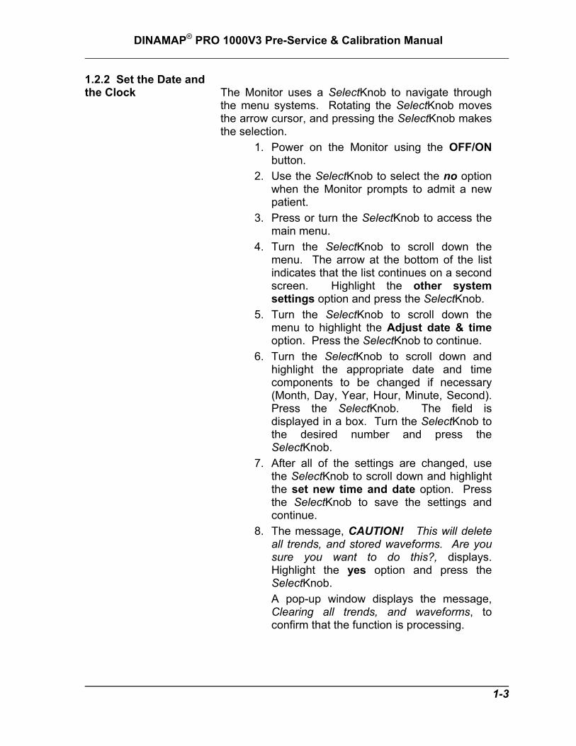
1.2.2 Set the Date and the Clock The Monitor uses a SelectKnob to navigate through
the menu systems. Rotating the SelectKnob moves the arrow cursor, and pressing the SelectKnob makes the selection.
1. Power on the Monitor using the OFF/ON button.
2. Use the SelectKnob to select the no option when the Monitor prompts to admit a new patient.
3. Press or turn the SelectKnob to access the main menu.
4. Turn the SelectKnob to scroll down the menu. The arrow at the bottom of the list indicates that the list continues on a second screen. Highlight the other system settings option and press the SelectKnob.
5. Turn the SelectKnob to scroll down the menu to highlight the Adjust date & time option. Press the SelectKnob to continue.
6. Turn the SelectKnob to scroll down and highlight the appropriate date and time components to be changed if necessary (Month, Day, Year, Hour, Minute, Second). Press the SelectKnob. The field is displayed in a box. Turn the SelectKnob to the desired number and press the SelectKnob.
7. After all of the settings are changed, use the SelectKnob to scroll down and highlight the set new time and date option. Press the SelectKnob to save the settings and continue.
8. The message, CAUTION! This will delete all trends, and stored waveforms. Are you sure you want to do this?, displays. Highlight the yes option and press the SelectKnob. A pop-up window displays the message, Clearing all trends, and waveforms, to confirm that the function is processing.
1-3

DINAMAP® PRO 1000V3 Pre-Service & Calibration Manual
1.2.3 Parameter Level Functional Testing After the initial configuration is complete, perform
functional testing of each of the parameters. Using the accessories supplied with the Monitor, initialize the Monitor in such a way that only one parameter is functioning at a time.
Left Side View of Monitor
Functional tests to be performed:
• A blood pressure test is carried out by connecting the supplied hose and cuff together, then attaching them to the NIBP Connector on the left side of the Monitor. Press the GO/STOP hardkey on the front to begin the NIBP cycle.
• Connect the supplied temperature probe to the corresponding connection (see illustration above). A predictive temperature begins once the probe is removed from the holster on the left side. Replace the probe after completion of the Temp cycle.
1-4

DINAMAP® PRO 1000V3 Pre-Service & Calibration Manual
The SpO2 sensor used depends on the Monitor configuration.
Nellcor SpO2 configured monitors use an assembly consisting of two parts: the DS-100A, and the extender cable DOC-10.
Masimo SpO2 configured monitors use an assembly consisting of an interface cable and a sensor.
• Connect the cables prior to attaching to the
Monitor. An SpO2 reading displays within moments of attaching the sensor to either an SpO2 simulator or to your finger.
• Connect the ECG lead connector to the ECG trunk cable prior to connecting to the Monitor. The simplest way to function test the ECG circuits is through the usage of an ECG simulator.
1. Set the simulator to normal heart rate. 2. Set ECG amplitude to 1.5mV, BPM to
80. 3. Set respirations to 20 RPM and the
delta ohms to 1.0. 4. Verify that the ECG waveform is
displayed. 5. Sequentially remove and reattach leads
I, II, and III, and verify each time that LEAD OFF displays.
6. From the ECG menu, select turn parameter off option.
1-5

DINAMAP® PRO 1000V3 Pre-Service & Calibration Manual
1.3 PERIODIC MAINTENANCE 1.3.1 Required Perform the following maintenance procedures as
required. 1.3.1.1 Integrity of Hoses and Cuffs When the pneumatic integrity of any NIBP cuff or
hose is in doubt, replace the cuff and hose, and discard the questionable accessories.
1.3.1.2 Cleaning of the Monitor
CAUTION! Do not clean Monitor with isopropyl alcohol or
other solvents. Do not immerse unit.
Wipe the exterior of the Monitor with a cloth slightly dampened with a mild detergent or normal hospital bactericides. Use dishwashing detergents such as:
IVORY® and JOY® (registered trademarks of Procter & Gamble Corp.)
PALMOLIVE® (registered trademark of Colgate-Palmolive Corp.).
1.3.1.3 Cleaning of Accessories Clean the adult cuffs supplied for use with the Monitor
by hand washing in warm, soapy water. However, take care to avoid entry of water into the cuff and hoses at any time. If water enters the cuff, dry the cuff by passing air through it.
The neonatal cuffs are for single patient use - discard if they become soiled. Clean cuffs and hoses with a cloth slightly dampened with mild detergent. Do not immerse hoses. Do not immerse cuffs without prior application of cuff hose caps.
1-6

DINAMAP® PRO 1000V3 Pre-Service & Calibration Manual
Clean SpO2 sensor surface before and after each patient use. Reusable sensors can be wiped with a 70% alcohol solution. If low level subsection is required, wipe with a 1:10 bleach solution. Do not use undiluted bleach (5-5.25% sodium hypochlorite) or any other cleaning solution other than those recommended here or in the directions for use for the sensor being used. Permanent damage to the sensor could occur. Do not immerse the sensor in water or these cleaning solutions because the sensor and its connector are not liquid proof. Do not sterilize the sensor by irradiation, steam autoclave, or with ethylene oxide. Refer to directions or use for the appropriate NELLCOR® sensor. Follow manufacturer's instructions for cleaning ECG lead wires and cable. Compatible cleaning and disinfecting solutions are dishwashing detergents such as: • IVORY® and JOY® (registered trademarks of
Procter & Gamble Corp.) • PALMOLIVE® (registered trademark of Colgate-
Palmolive Corp.). • Chlorine bleach disinfectant, 5.25%, three-quarter
cup per gallon of water. CAUTION! Do not apply isopropyl alcohol to the Monitor -
some parts can become marred and cracked.
• Isopropyl alcohol (for accessories only). • Cidex Formula 7 (registered trademark of Johnson
& Johnson Medical Products, Inc.) or pHisoHex (registered trademark of Winthrop-Breon Laboratories).
Quaternary-based germicidal detergents such as: • VESTAL INSURANCE® (registered trademark of
the Vestal Corp.). • HI-TOR PLUS® (registered trademark of the
Huntington Corp.). • VIREX® (registered trademark of S.C. Johnson &
Son Corp.).
1-7

DINAMAP® PRO 1000V3 Pre-Service & Calibration Manual
For the above, follow manufacturers' recommendations for dilution rate and use. These recommendations are not an endorsement of the manufacturers or of the effectiveness of these materials for cleaning or disinfecting.
1.3.1.4 Long-Term Storage If it becomes necessary to store the Monitor for an
extended period of time, remove all attached accessories. Attach the original packing inserts, and place the Monitor into the original shipping container. Generally, long-term storage of a nickel-metal hydride battery in either a charged or discharged condition has no permanent effect on capacity. Capacity loss due to self-discharge is reversible, and nickel-metal hydride batteries can recover to full capacity by proper recharging. For example, cycling through repeated charge/discharge cycles can restore a full capacity of a nickel-metal hydride battery that was stored at room temperature for up to one year. Long-term storage at high temperatures can lead to deterioration of seals and separators and should be avoided.
1.3.2 Annual Procedures Perform the test procedures described in paragraph
1.7 every twelve months, or whenever the accuracy of any reading is in doubt.
NOTE: An internal, 3.6V NiMh battery acts as an alarm
backup and maintains the nonvolatile RAM memory when the Monitor is off or away from AC mains. A system alarm message is generated if backup battery replacement is required.
1-8

DINAMAP® PRO 1000V3 Pre-Service & Calibration Manual
1.4 CARE OF STORAGE BATTERIES The Monitor uses one nickel-metal-hydride (NiMH)
storage battery. The battery can be charged at any time without reducing the charging capacity.
1.4.1 Procedures For First Use Follow these procedures to condition a new NiMH
battery and optimize its performance: The internal battery automatically charges when the AC power supply is in use. When the battery is charged for the first time, the charger may indicate prematurely that charging is complete. This is normal and can happen with all rechargeable batteries when first charged.
1.4.2 Battery Charging The Monitor charges the NiMH battery whenever the AC power supply is in use. The Monitor automatically senses if the battery needs recharging. Battery charging continues whenever it’s needed while the Monitor is connected to the AC power supply, even when the Monitor is turned off.
• Batteries should be charged before first use or after prolonged periods of storage.
• The battery should be charged before use, as a charged battery loses some charge when left in storage.
• The battery should be charged at room temperature (59° F - 86° F; 16° C - 30° C).
• It is normal for the battery to become warm during charging or after use.
• Batteries can be charged or topped-off at any time. It is not necessary to wait until they are fully discharged.
• If the Monitor is idle for extended periods, it should be fully charged once a month to ensure optimum performance.
1-9

DINAMAP® PRO 1000V3 Pre-Service & Calibration Manual
1.4.3 Battery Troubleshooting
Trouble Probable Cause Remedy
Battery inoperative or does not last very long.
Battery not fully charged. Battery in long-term storage or nonuse.
Charge and discharge battery up to three times for optimum performance.
Battery will not charge.
Charging battery in unusually cold or hot temperatures.
Charge at basic room temperature of 59° F (16° C) to 86° F (30° C). Slowly bring battery to basic room temperature before recharging. Batteries cannot be fully charged unless internal temperatures between 57° F (15° C) and 109° F (40° C).
1-10

DINAMAP® PRO 1000V3 Pre-Service & Calibration Manual
1.5 SAFETY RESISTANCE TESTING Using a safety analyzer (Dynatech Nevada Model
235A or equivalent), check the ground resistance of the Monitor. Refer to the Rear View graphic for locations of test points.
Rear View of Monitor with Safety Connection Exposed
Earth-To-Secondary Continuity
Verify that the resistance between the AC Mains ground pin and the External DC connector ground is less than 1Ω.
AC Mains Leakage – Normal Polarity
For the following tests, 260 VAC is applied at the Monitor’s AC Mains input in normal polarity.
1-11

DINAMAP® PRO 1000V3 Pre-Service & Calibration Manual
No Fault Verify that the leakage from line to ground pin is less than 500 µA.
Open Ground Disconnect the Monitor’s ground lead from earth ground (for the duration of this test only) and verify that the leakage from line to ground pin is less than 500 µA.
Open Neutral Open the Monitor’s neutral lead (for this test only) and verify that the leakage from line to ground is less 500 µA.
AC Mains Leakage – Reverse Polarity
For the following tests, 260 VAC is applied at the Monitor’s AC Mains input in reverse polarity (inputs to line pin and Neutral pin reversed).
No Fault Verify that the leakage from line to ground pole is less than 500 µA.
Open Ground Disconnect the Monitor’s ground lead from earth ground (for the duration of this test only) and verify that the leakage from line to ground is less than 500 µA.
Open Neutral Open the Monitor’s Neutral lead (for the duration of this test only) and verify that the leakage from line to the ground is less than 500 µA.
ECG Leakage Using ECG probe adapter, verify that the leakage from the ECG circuit to earth ground is less than 50 µA.
Temperature Leakage Using Temperature probe adapter, verify that the leakage from the Temperature circuit to earth ground is less than 150 µA.
SPO2 Leakage Using SPO2 probe adapter, verify that the leakage from the SPO2 circuit to earth ground is less than 150 µA.
1.6 HI-POT TESTS
Hi-Pot testing is done on every unit at the factory and should not be repeated unnecessarily nor performed more often than required. (If unit is opened for repair, Hi-Pot testing is required otherwise hi-pot test may be exempted.)
CAUTION! High voltage will be applied to the monitor under test
when the hi-pot START switch is activated.
1-12

DINAMAP® PRO 1000V3 Pre-Service & Calibration Manual
1.6.1 AC Mains Hi-Pot
1. Set the hi-pot timer for 1 minute. 2. If not already set, set the hi-pot TEST VOLTAGE to 1.5
kilovolts AC. To set the hi-pot TEST VOLTAGE for the first time:
a. Turn the hi-pot power switch off. b. Disconnect the cables from the front of the hi-
pot. c. Shut off the timer. d. Push on the START switch. e. Adjust the TEST VOLTAGE knob until the
meter reads 1.5 kilovolts AC. f. Push STOP and turn timer back on. g. Connect the hi-pot cables to the front of the hi-
pot. 3. Turn the hi-pot power switch off.
4. Plug a power cord into the monitor. 5. Connect the HOT lead from the hi-pot tester to the power
cord line and neutral leads. 6. Connect the GND lead from the hi-pot tester to the power
cord earth ground lead. 7. Turn the hi-pot power switch on. 8. Momentarily raise the hi-pot START switch to start the
test. 9. If the hi-pot does not alarm before the timer expires, the
monitor passed the test. 10. Turn the hi-pot power switch off.
1.6.2 ECG / SPO2 / Temp Hi-pot
1. Turn the hi-pot switch off. 2. Set-up the hi-pot tester to test at 1.5 kilovolts AC for 1
minute (as in the previous test). 3. Insert the ECG, SPO2 and Temperature test adapters
into the monitor under test. 4. Connect the GND hi-pot test cable to the AC MAINS
cable earth ground. 5. Connect the HOT hi-pot test cable to the ECG test
adapter. 6. Turn the hi-pot power switch on. 7. Momentarily raise the hi-pot START switch to start the
test. 8. If the hi-pot does not alarm before the timer expires, the
monitor passed the test. 9. Repeat steps 5 through 8 individually for the SPO2 and
Temperature adaptors.
1-13

DINAMAP® PRO 1000V3 Pre-Service & Calibration Manual
10. Turn the hi-pot power switch off and remove hi-pot
cables. 11. Disconnect the probe adapters from the monitor under
test. 1.7 SERVICE MODE OPERATION The Monitor service mode exercises the built-in
diagnostic features of the Monitor and the installed parameters. Access the service mode from a cold start by proceeding as follows:
1. Power on the Monitor using the OFF/ON button.
2. Use the SelectKnob to select the no option when the Monitor prompts to admit a new patient.
3. Press or turn the SelectKnob to access the main menu.
4. Turn the SelectKnob to scroll down the menu. The arrow at the bottom of the list indicates that the list continues on a second screen. Highlight the other system settings option and press the SelectKnob.
5. Highlight the go to service mode option and press the SelectKnob. Turn the SelectKnob and press the knob again to answer yes at the prompt to display the dialog box.
6. A row of numbers is displayed at the bottom of the screen. Turn the SelectKnob and move the arrow to the desired number, then press the knob to select the number. Enter the service mode password, 2-2-1-3.
7. After the password is selected, turn the SelectKnob to the DONE option and press the knob.
8. In the process of entering the Service Mode, the Monitor resets itself. Successful entry into
1-14

DINAMAP® PRO 1000V3 Pre-Service & Calibration Manual
the Service Mode is indicated by the Service Menu title displayed on the upper left side of the display.
NOTE: The service mode can also be entered directly from a
cold start by pressing and holding the following two keys until full power-up: OFF/ON and AUTO-BP. To make any changes to the Service Menu, the password has to be entered: press the SelectKnob to enter service password.
9. At this point the Service Mode main screen
should be present in the main display, as shown below. The service menu service parameters area displays a list that corresponds to the number and type of parameters that have been detected by the Monitor. If the service mode was entered directly (as described in the NOTE above), enter service password appears above the service parameters on the service menu. The password MUST be entered (as described in Steps 5 and 6) before any changes to calibration can be made.
1-15
DINAMAP® PRO 1000V3 Pre-Service & Calibration Manual
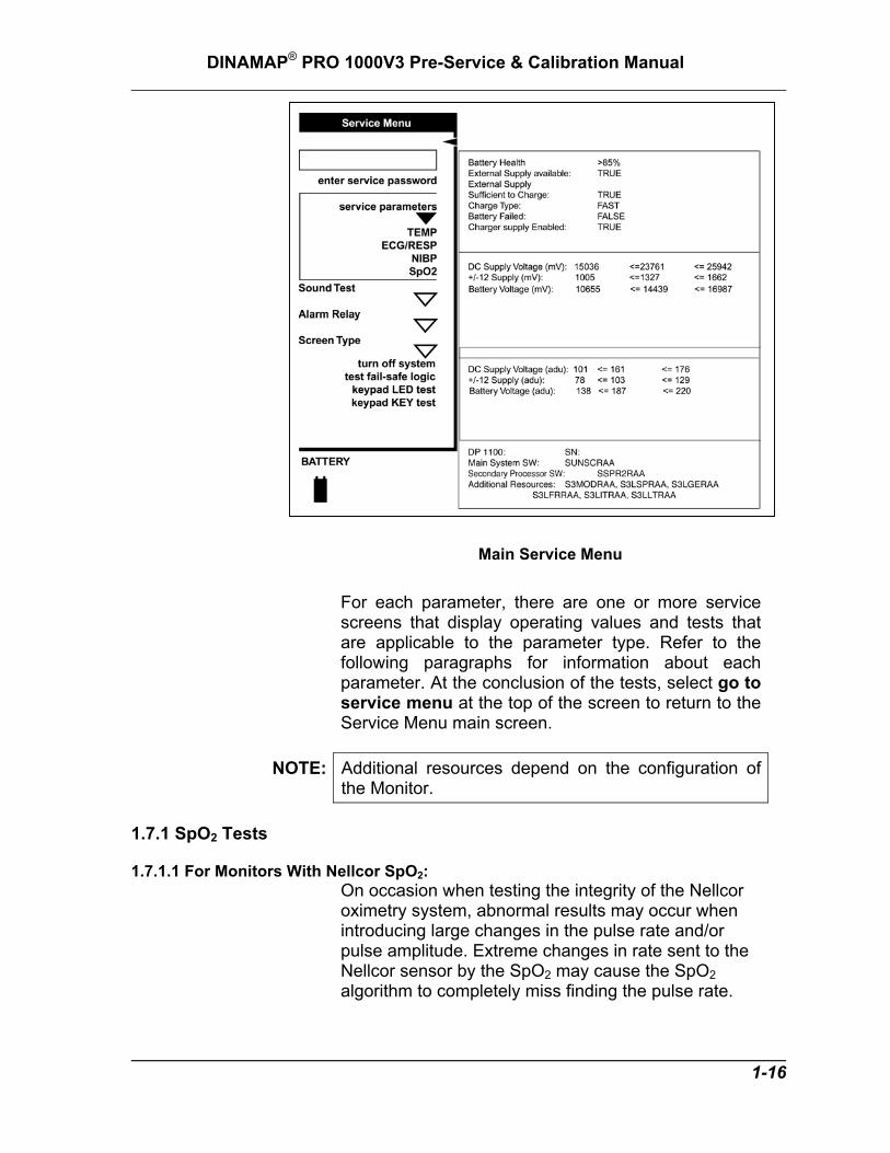
Main Service Menu For each parameter, there are one or more service screens that display operating values and tests that are applicable to the parameter type. Refer to the following paragraphs for information about each parameter. At the conclusion of the tests, select go to service menu at the top of the screen to return to the Service Menu main screen.
NOTE: Additional resources depend on the configuration of the Monitor.
1.7.1 SpO2 Tests 1.7.1.1 For Monitors With Nellcor SpO2:
On occasion when testing the integrity of the Nellcor oximetry system, abnormal results may occur when introducing large changes in the pulse rate and/or pulse amplitude. Extreme changes in rate sent to the Nellcor sensor by the SpO2 may cause the SpO2 algorithm to completely miss finding the pulse rate.
1-16
DINAMAP® PRO 1000V3 Pre-Service & Calibration Manual
This is an expected result. To work around this, incrementally step up or down the settings on your SpO2 simulator and allow the monitor to detect and display the new pulse rate or saturation. Nellcor recommends use of the SRC-MAX Portable Tester for use with PRO Monitors equipped with the Nellcor SpO2 system.
1.7.1.1 For Monitors With Masimo SpO2: Masimo recommends BIO-TEK SpO2 simulators.
Test Procedure:
1. Disconnect all sensor cables from the SpO2 Parameter, and ensure that the SpO2 parameter is listed within the main Service Menu.
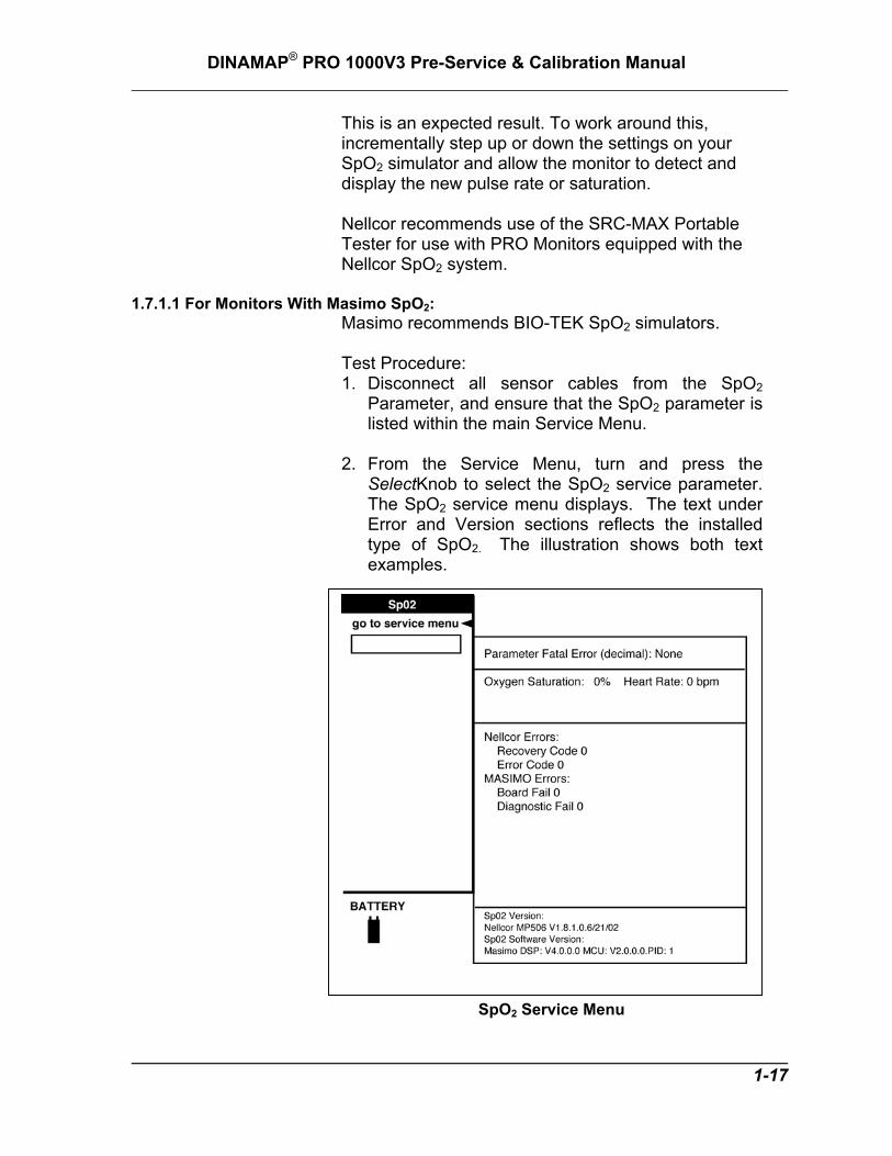
2. From the Service Menu, turn and press the
SelectKnob to select the SpO2 service parameter. The SpO2 service menu displays. The text under Error and Version sections reflects the installed type of SpO2. The illustration shows both text examples.
SpO2 Service Menu
1-17

DINAMAP® PRO 1000V3 Pre-Service & Calibration Manual
3. All SpO2 mode operations take place with Masimo and Nellcor power-up defaults. No menu settings are reflected.
4. Connect the appropriate SpO2 simulator and cable to the side interface panel SpO2 connector. Be sure it is fully seated in the socket.
5. Set simulator for 98% saturation and 80BPM. Verify that the Monitor responds accordingly by displaying the proper heart rate value and saturation value.
1.7.2 NIBP Tests
NIBP Service Menu Perform the following tests to determine that the NIBP parameter is functioning normally.
1-18

DINAMAP® PRO 1000V3 Pre-Service & Calibration Manual
1.7.2.1 Leak Test
CAUTION! Calibration equipment should always be kept dry and
free of particulate matter. Moisture or foreign substances introduced to the pneumatic system will likely cause damage to the Monitor and/or accessories. Inspection of pneumatic hose O-rings is recommended once a year.
1. Using the calibration kit (part number 320-246), an
adult cuff and air hose, and a manometer, set up the equipment as shown in Figure 1-1. Connect the hose to the NIBP Parameter. Make sure that all of the fittings are tight, and that the valve on the manual inflation bulb is fully closed.
Figure 1-1. NIBP Test Setup
1-19

DINAMAP® PRO 1000V3 Pre-Service & Calibration Manual
2. From the Service Menu, turn and press the
SelectKnob to select the NIBP service parameter.
3. Turn and press the SelectKnob to select start leak test. Observe that the Leak Test Status message on the menu indicates Busy.
4. Observe that the pump begins inflating the system to 200 ~ 210 mmHg, at which point the pump operation will cease. The Monitor will begin to calculate system pressure loss rate.
5. After about 60 seconds, the pressure is released, and the menu should display Leak Test Status Passed, and the Leak Test Results indication should be a value less than 6. Service Error: None should continue to display.
6. If the menu displays Leak Test Failed, continue to Step 9.
7. Using the calibration kit (part number 320-246), an adult cuff and air hose, and a manometer, set up the equipment as shown in Figure 1-2.
Figure 1-2 Leak Test Setup
1-20

DINAMAP® PRO 1000V3 Pre-Service & Calibration Manual
8. Close the pressure release valve on the
manometer inflation bulb and slowly increase the pressure to 200-mmHg ±1 mmHg.
9. Verify the pressure indicated on the manometer remains within 5 mmHg of 200 mmHg for 60 seconds. If not, either the cuff or hose or both may be defective. If the cuff and hose pass this test, repeat Steps 1 through 7 to try to isolate the leak. Repeat the leak test for all cuff and hose combinations to be used with the Monitor.
CAUTION! Calibration equipment should always be kept dry and free of particulate matter. Moisture or foreign substances introduced to the pneumatic system will likely cause damage to the Monitor and/or accessories.
1.7.2.2 NIBP Calibration Check
1. Using the calibration kit (part number 320-246), an adult cuff and air hose, and a manometer, set up the equipment as shown in Figure 1-1. Connect the hose to the NIBP Parameter. Make sure all fittings are tight, and that the inflation bulb valve is closed tightly.
NIBP Service Menu
2. From the Service Menu, turn and press the
SelectKnob to select the NIBP service parameter. 1-21

DINAMAP® PRO 1000V3 Pre-Service & Calibration Manual
3. Turn and press the SelectKnob to select
pneumatic reset. 4. Turn and press the SelectKnob to select valve
close. 5. Observe that both PT1 Pressure and PT2
Pressure equal initial values of zero mmHg (0 mmHg).
6. Connect the pneumatic hose to the Monitor’s NIBP port.
7. Fold the adult cuff so the index line is aligned with the inner range mark on the inside of the cuff. Make sure all fittings are tight, and that the valve on the inflation bulb is closed tightly. If there is doubt about the integrity of the system, perform the leak test (paragraph 1.7.2.1) before continuing.
8. Close the pressure release valve on the manometer inflation bulb and manually pump up the pressure until the manometer indicates approximately 220 mmHg.
9. Allow the pressure to stabilize for at least one minute. Then open the pressure release valve on the manometer inflation bulb and carefully bleed off pressure until the manometer indicates 200 mmHg.
10. Observe that the values of PT1 Pressure and PT2 Pressure on the menu indicate within 1 mmHg of the pressure shown on the manometer.
11. Verify the system linearity by repeating steps 8 & 9 using manometer readings of 250 mmHg, 150 mmHg, and 50 mmHg. Observe that the PT1 and PT2 Pressures are within 3 mmHg of manometer readings for each of these pressure indications. If not, proceed to paragraph 1.7.2.3.
1.7.2.3 Pressure Recalibration
CAUTION! Calibration equipment should always be kept dry and free of particulate matter. Moisture or foreign substances introduced to the pneumatic system will likely cause damage to the Monitor and/or accessories.
1. Always enter Service Mode with the password, as
described in paragraph 1.7, before attempting to recalibrate equipment.
1-22

DINAMAP® PRO 1000V3 Pre-Service & Calibration Manual
2. Using the calibration kit (part number 320-246), an
adult cuff and air hose, and a manometer, set up the equipment as shown in Figure 1-1. Do not connect the pneumatic hose to the NIBP port yet.
3. From the Service Menu, Turn and press the SelectKnob to select the NIBP service parameter.
NIBP Service Menu
4. Turn and press the SelectKnob to select
pneumatic reset. 5. Turn and press the SelectKnob to select valve
close. 6. Observe that both PT1 Pressure and PT2
Pressure display initial values of 0 on the menu. 7. Turn and press the SelectKnob to select cal press
zero. Observe that the message Inflate System to 200 mmHg Then Hit ‘Cal Press 200’ is displayed on menu.
8. Connect hose to NIBP Parameter. 9. Fold the adult cuff so the index line is aligned with
the inner range mark on the inside of the cuff. Make sure all fittings are tight, and that valve on inflation bulb is closed tightly. If there is doubt about the integrity of the system, perform the leak test (paragraph 1.7.2.1) before continuing.
10. Close the pressure release valve on the manometer inflation bulb and manually pump up
1-23

DINAMAP® PRO 1000V3 Pre-Service & Calibration Manual
the pressure until the manometer indicates approximately 220 mmHg.
11. Allow the pressure to stabilize for at least a minute. Then open the pressure release valve on the manometer inflation bulb and carefully bleed off pressure until the manometer indicates a little more than 200 mmHg.
12. Turn and press the SelectKnob to select cal press 200, but do not press the knob.
13. When the manometer indicates exactly 200 mmHg, press the Rotor. Observe that system pressure is released, and the message: !!!!! CAL INFO NOT SAVED!!!!! is displayed on menu.
14. Turn and press the SelectKnob to select save cal info. If the system is operating normally, the menu displays Service Error: None, and the calibration setting is saved.
15. Repeat the calibration check procedure (paragraph 1.7.2.2) to confirm the calibration setting.
1.7.2.4 Overpressure Tests
CAUTION! Calibration equipment should always be kept dry and
free of particulate matter. Moisture or foreign substances introduced to the pneumatic system will likely cause damage to the Monitor and/or accessories.
1. Using the calibration kit (part number 320-246), an
adult cuff and air hose, and a manometer, set up the equipment as shown in Figure 1-1. Connect the hose to the NIBP Parameter. Make sure all fittings are tight, and that valve on inflation bulb is closed tightly.
2. From the Service Menu, Turn and press the SelectKnob to select the NIBP service parameter.
3. Turn and press the SelectKnob to select pneumatic reset.
4. Turn and press the SelectKnob to select valve close.
5. Observe that the menu displays Overpressure Selected Adult. If not, turn and press the SelectKnob to select adult ovp select.
1-24
6. Turn and press the SelectKnob to select inflate on. The pump should begin to inflate the system.

DINAMAP® PRO 1000V3 Pre-Service & Calibration Manual
7. Watch the pressure indication increase on the
manometer, and observe that the pump is shut down and the pressure is released when the manometer indicates in the range of 300 to 330 mmHg. Observe that the menu displays Service Error: None.
8. Turn and press the SelectKnob to select pneumatic reset.
9. Turn and press the SelectKnob to select valve close.
10. Turn and press the SelectKnob to select neo ovp select. Observe that the menu displays Overpressure Selected Neo.
11. Turn and press the SelectKnob to select inflate on. The pump should begin to inflate the system.
12. Watch the pressure indication increase on the manometer, and observe that the pump is shut down and the pressure is released when the manometer indicates in the range of 150 to 165 mmHg. Observe that the menu displays Service Error: None.
13. If the overpressure test results in an “out of tolerance” condition, contact GE Medical Systems Information Technologies at 877-274-8456 for assistance.
1.7.3 ECG Tests
Connect the ECG leads to the ECG trunk cable prior to connection to the Monitor. The simplest way to function test the ECG circuitry is through the usage of an ECG simulator with the Monitor in normal monitoring mode.
1. Set ECG simulator to 80BPM Paced. 2. Set ECG simulator amplitude to 1.0mV 3. Press ON/OFF button to power up UUT. 4. Select no at new patient prompt. Set the ECG
high alarm to 150 and the low alarm to 50. 5. Verify that the ECG waveform is displayed on
LCD display. 6. From ECG menu, select Pace 1 and verify
paced marker on display waveform. 7. From ECG menu, select Pace 2 and verify
paced marker on display waveform. 8. From ECG menu, select pace detection off.
Turn paced off on simulator. 1-25

DINAMAP® PRO 1000V3 Pre-Service & Calibration Manual
9. After unit has learned the patient waveform
change the BPM to 30. 10. Verify “HR LOW” alarm with HR 30 ±4 on unit. 11. Set ECG simulator to 160BPM 12. Verify that the ECG waveform is displayed on
the LCD display. 13. Verify “HR HIGH” alarm with HR 160 ± 4 on
unit. 14. Set ECG simulator to 80 BPM. 15. Set ECG high alarm to 200 and low alarm to
10. 16. Set ECG simulator to VTACH. 17. Verify “ECG VTACH” alarm and HR is 180 ± 4. 18. Set ECG simulator to 80 BPM 19. Press silence hardkey to acknowledge the
alarm and verify HR is 80 ± 4. 20. Connect scope to analog output using 1/8”
stereo plug (+ to ring, - to shield). 21. Verify that the ECG waveform is displayed on
the scope (amplitude approximately 1V). 22. Disconnect scope from analog output. 23. Remove and reattach leads I, II, III,
sequentially and verify “ECG LEAD FAIL” alarm on display.
24. From ECG menu, select turn parameter off.
1-26

DINAMAP® PRO 1000V3 Pre-Service & Calibration Manual
1.7.4 RESP Test
1. Set simulator Respiration to 20 BrPM . 2. Set simulator delta ohms to 1.0. 3. Set simulator Baseline to 1K, and Lead to II. 4. Verify that the RESP waveform is displayed on
the LCD display 5. Record and verify the UUT RESP reading. 6. Set simulator Respiration to 60 BrPM. 7. Record and verify the UUT RESP reading. 8. From RESP menu, select turn parameter off.
1.7.5 TEMP Tests (if fitted)
The Pro1000 temperature system uses ALARIS Model 2885 and 2886 temperature probes. This system is self-calibrating. The only maintenance required is to verify that the temperature functions work properly. These checks require an IVAC probe simulator (P/N TE 1811), available from ALARIS Medical Systems, Inc., San Diego, CA. (619) 458-7000. GE Medical Systems Information Technologies does not stock this tester.
1. Disconnect any temperature probe from the IVAC
temperature connector. 2. From the Service Menu, turn and press the
SelectKnob to select the TEMP service parameter. The TEMP service menu displays as shown below.
3. To check the temperature system, connect the IVAC probe simulator to the temperature probe connector on the side interface panel and insert a temperature probe into the holster.
4. Set the probe simulator to 98.6, verify and record the displayed temperature is 98.6oF +/-0.2oF. Set the probe simulator for the other values(80.2 and 107.8) and verify and record the displayed temperatures.
1-27

DINAMAP® PRO 1000V3 Pre-Service & Calibration Manual
Temperature Service Menu
5. Set the probe simulator to B.P. Verify the temperature displayed is 106.0+/-0.2oF and Probe indication is IN. Press the broken probe button and verify the monitor displays “Probe Disconnected”.
6. Set simulator for both Oral and Rectal and verify the correct probe type is indicated.
7. Remove and insert probe from holster and verify probe IN/OUT detection.
Calibration verification is complete. Disconnect the probe simulator and install the temperature probe. If the Monitor does not pass the calibration verification then contact customer service.
1.7.6 RECORDER Tests
1. Ensure that paper has been loaded into the Recorder Parameter, and you are presently in the Service Mode.
2. From the Service Menu, turn and press the SelectKnob to select the RECORDER test option. Turn and press the SelectKnob to choose the Print 1 Waveforms option. Turn and press the SelectKnob to choose the Wave Test 6.25mm/S
1-28

DINAMAP® PRO 1000V3 Pre-Service & Calibration Manual
option. Verify that all printouts are of even tone and all pixels are present.
Sample 6.25 mm/sec – 1 waveform chosen
3. Allow for the paper to spool out a 12 inch printed section then press Stop Test.
4. Select Vertical Text test. Verify that the printed text is legible and evenly spaced.
1-29

DINAMAP® PRO 1000V3 Pre-Service & Calibration Manual
5. Select Horizontal Text test. Verify that the printed
text is legible and evenly spaced.
Horizontal Text Test Printout 1.7.7 Battery Tests From within the Service Menu, battery status
information is displayed on the upper right-hand section of the display.
Battery/ Power Supply menu
1-30

DINAMAP® PRO 1000V3 Pre-Service & Calibration Manual
Battery Health: the Monitor’s software approximates the true status of the battery’s health. The value indicated is displayed as both a number (in percentage) and as an icon on the bottom-left area of the display.
External Supply available: True indicates a source other than the internal battery is providing power for the Monitor, and a source to charge the internal battery.
External Supply Sufficient to Charge: If the voltage from the external supply is greater than that of the internal battery, the Monitor will display the results as TRUE. False will result if either the voltage is equal to or lower than the power available from the internal battery.
Charge Type: Fast or Slow.
Battery Failed: Any result other than FALSE, indicates that the internal battery has suffered a failure and should be investigated.
Charger Supply Enabled: Should always be TRUE as the Monitor consistently attempts to keep the battery at its’ fullest capacity. A FALSE indicates the battery may be faulty or not installed, or the charge circuit may have failed. Also, if no external source of power is available, the Monitor registers a FALSE result.
1.7.7.1 Test Procedure: 1. Verify AC Mains indicator on front panel of unit
near OFF/ON button is lit with AC Mains plugged in.
2. Turn on Monitor. 3. Remove AC Mains and verify uninterrupted battery
operation. Note: If this fails check fuse in communications well.
4. Verify battery indicator is lit near OFF/ON button.
Note: Battery life is dependent upon battery usage. A fully charged battery should last 120 minutes (+/- 10 min) using the following setup:
1-31

DINAMAP® PRO 1000V3 Pre-Service & Calibration Manual
(NIBP: 5-min auto cycle with adult cuff. ECG, RESP, SpO2: Active. TEMP: predictive mode. Printer: printing 2 waveforms for 1 min every 20 min at 25 mm/sec.).
1.7.8 Failsafe Logic Test
1. From the Service Menu, turn the SelectKnob to select test fail-safe logic. A dialogue box displays:
CAUTION! This causes the system to freeze for approximately 2 seconds then enter the fail-safe mode. Continue?
1. Turn the SelectKnob to the yes option and
press the knob. 2. After two seconds, the system freezes, an
alarm sounds, and the screen goes blank. Recycle the system power using the OFF/ON button. To return to the Service Mode, repeat the procedures as described in Section 1.7.
1.7.9 Keypad LED Test
1. From the Service Menu, rotate and press the SelectKnob to select keypad LED test. Observe that each of the keys on the Monitor face, illuminate one key at a time. With the exception of the OFF/ON key, observe whether or not any of the keys fail to illuminate.
2. After all keys have been tested, press the SelectKnob again to stop the test.
1.7.10 Keypad KEY Test
1-32
1. From the Service Menu, rotate and press the SelectKnob to select keypad KEY test. With the

DINAMAP® PRO 1000V3 Pre-Service & Calibration Manual
exception of the OFF/ON key, observe that each key press toggles the key LED color and produces a beep tone.
2. After all keys have been tested, press the SelectKnob again to stop the test.
1.7.11 Sound Test Verify that the Monitor produces tones of various pitches when this option is selected.
1.7.12 Communications Tests 1.7.12.1 Set up Terminal
1. Connect serial communication cable from PC to rear of UUT (DB15).
2. Invoke terminal program with settings: 9600 baud, No parity, 8 bits, 1 stop bit, flow = xon/xoff , no cr/lf character enabled
Note: Terminal must be set to an available communication port (comm1 is default) or redirect the terminal program to an appropriate port.
1.7.12.2 Configure UUT for Communication 1. Rotate the rotor to get to the Main menu and
select other system settings. 2. Select go to config mode, select yes at the
verification prompt. 3. Enter password 2508, and select done. 4. After the unit reboots, rotate the rotor to display
the Configuration Menu. 5. Select other system settings, then Config
HostComm. 6. Configure the COMMS port for Remote access
Serial 2. 7. Select Serial 2 setup and configure Serial 2 for
ASCII cmd, 9600 baud. 8. Select go to previous menu, then save default
changes. 9. Select exit config mode, select yes at the
verification prompt. 10. After the unit reboots, select no at “new patient”
prompt.
1-33

DINAMAP® PRO 1000V3 Pre-Service & Calibration Manual
1.7.12.3 Communication Test
1. Execute the following commands (by sending text files from the terminal program) and verify the appropriate response. Note: each string is preceded by a space. “∧” represents the space character.
“∧NC0!E” Verify that UUT pump starts. “∧ND!5” Verify that UUT pump stops. “∧TB!9” Verify return temperature status
in the form “…TB-99999…”. 1.7.13 Remote Alarm Test
1. Install test plug assembly to DMM which inserts a 470Ω resistor across DMM terminals.
2. Use the DMM to measure voltage between pins 4 and 8 of DB15 connector (see Figure 5) and record the result.
3. Select Alarm relay / ON. 4. Measure and record voltage between pins 4 and
8 of DB15 connector. 5. Select Alarm relay / OFF. 6. Remove test plug assembly from DMM.
1.7.14 Turn off system Selection of this menu item brings up a dialogue
window requesting you to confirm your decision:
CAUTION! This turns the system off. Are you sure you want to do this?
Selecting yes powers off the Monitor. Selecting no returns the Monitor to the Service Menu.
1.8 SERVICE MODE EXIT To exit the service mode and power off the Monitor,
locate and press the key marked OFF/ON at the front of the Monitor.
1-34

DINAMAP® PRO 1000V3 Pre-Service & Calibration Manual
12345
6789
9 PIN FEMALE (FRONT VIEW)
1 2 3 4 5 7 8
9
6
101112131415
15 PIN MALE (FRONT VIEW)
Figure 1-3. SERIAL COMMUNICATION CABLE
1-35

DINAMAP® PRO 1000V3 Pre-Service & Calibration Manual
1234578
9
6
10 11 12 13 14 15
15 PIN FEMALE (FRONT VIEW)
Figure 1-4. DB15 REAR PANEL CONNECTOR
1 2 3 4 5 7 8
9
6
101112131415
15 PIN MALE (FRONT VIEW)
470
REMOTE ALARM TEST PLUG
Figure 1-5. TEST PLUG ASSEMBLY
1-36

DINAMAP® PRO 1000V3 Service Manual
APPENDIX A: Test Record
APPENDIX A: Test Record A-1

DINAMAP® PRO 1000V3 Service Manual
APPENDIX A: Test Record A-2

DINAMAP® PRO 1000V3 Service Manual
TEST RECORD Model# Serial# .
Step Description Min Max Actual Pass Fail N/A
Safety Testing 4.5 External DC to GND Resistance (m) 0 1000 4.5 Normal no-fault leakage (µA) 0 500 4.5 Normal open-ground leakage (µA) 0 500 4.5 Normal open-neutral leakage (µA) 0 500 4.5 Reverse no-fault leakage (µA) 0 500 4.5 Reverse open-ground leakage (µA) 0 500 4.5 Reverse open-neutral leakage (µA) 0 500 4.5 ECG leakage (µA) 0 50 4.5 Temp Leakage (µA) 0 150 4.5 SPO2 Leakage (µA) 0 150
Hi-Pot Testing
4.6.1 AC Main Hipot (mA) 0 2.5 4.6.2 ECG (mA) 0 1 4.6.2 SPO2 (mA) 0 1.5 4.6.2 Temp (mA) 0 1.5
SpO2 Testing
4.7.1 SpO2 reading at 98% Saturation 96 100 4.7.1 BPM reading at 80BPM 76 84
NIBP Testing (Perform in Service Mode)
4.7.2.1 Leakage Test 4.7.2.2 UUT Pressure - 50 mmHg 47 53 4.7.2.2 UUT Pressure - 150 mmHg 147 153 4.7.2.2 UUT Pressure - 250 mmHg 247 253 4.7.2.4 Verify adult overpressure occurs between 300~330 mmHg 4.7.2.4 Verify neo overpressure occurs between 150~165 mmHg 4.7.2 Initial cuff inflation (Adult cuff) 161 195 4.7.2 Systolic Reading (120/80 Adult) 107 133 4.7.2 Diastolic Reading (120/80 Adult) 67 93 4.7.2 Heart Rate reading @ 80 BPM (NIBP) 76 84 4.7.2 Inflate/ Deflate cycle time <120 seconds 4.7.2 Initial cuff inflation (Neonatal cuff) 94 151 4.7.2 Systolic Reading (100/65 Neonatal) 87 123 4.7.2 Diastolic Reading (100/65 Neonatal) 52 78
ECG Testing (Perform in Monitor Mode)
4.7.3 Verify Waveform 4.7.3 Verify paced 1 marker on ECG signal 4.7.3 Verify paced 2 marker on ECG signal APPENDIX A: Test Record A-3

DINAMAP® PRO 1000V3 Service Manual
4.7.3 Verify HR LOW alarm and BPM at 30 26 34 4.7.3 Verify HR HIGH alarm and BPM at 160 156 164 4.7.3 Verify ECG VTACH alarm and BPM at 180 176 184
4.7.3 Verify ECG LEAD FAIL alarm
RESP Testing (Perform in Monitor Mode)
4.7.4 Verify Waveform 4.7.4 Verify RESP (@ 20 BPM) 17 23 4.7.4 Verify RESP (@ 60 RPM) 57 63 4.7.4 Verify Waveform 4.7.4 Verify RESP (@ 20 BPM) 17 23 4.7.4 Verify RESP (@ 60 RPM) 57 63
Temperature Testing (Perform in Service or Monitor Mode - requires Alaris Temp Simulator)
4.7.5 Measured Temp in ºF (98.6º nominal) 98.4 98.8 4.7.5 Measured Temp in ºF (80.2º nominal) 79.9 80.5 4.7.5 Measured Temp in ºF (107.8º nominal) 107.5 108.1 4.7.5 Probe Disconnected 4.7.5 Probe Type 4.7.5 Probe In/Out Detect
Recorder Testing
4.7.6 Recorder Test
Battery System Testing (Perform in Monitor Mode)
4.7.7 Verify AC Mains Indicator 4.7.7 Remove AC, Verify uninterrupted battery operation 4.7.7 Verify Battery LED is lit
Failsafe Logic Testing
4.7.8 Failsafe Logic
Front Panel LED Testing
4.7.9 Keypad LED Test
Front Panel Key Testing (Perform in Service Mode) 4.7.10 Verify appropriate responses to key presses
Sound Test
4.7.11 Speaker Test
Communications Testing
4.7.12 Verify pump starts, stops and temp status returns
Remote Alarm Test
4.7.13 Voltage between pins 4 and 8, alarm inactive 4.7 5.3
4.7.13 Voltage between pins 4 and 8, alarm active 0.0 0.1
APPENDIX A: Test Record A-4

DINAMAP® PRO 1000V3 Service Manual
Tested by:
Date:
Signature:
Facility:
APPENDIX A: Test Record A-5

DINAMAP® PRO 1000V3 Service Manual
APPENDIX A: Test Record A-6

DINAMAP® PRO 1000V3 Service Manual
APPENDIX B: Monitor Configuration Log
APPENDIX B: Monitor Configuration Log B-1

DINAMAP® PRO 1000V3 Service Manual
APPENDIX B: Monitor Configuration Log B-2

DINAMAP® PRO 1000V3 Service Manual
APPENDIX B: Monitor Configuration Log B-3

DINAMAP® PRO 1000V3 Service Manual
APPENDIX B: Monitor Configuration Log B-4

DINAMAP® PRO 1000V3 Service Manual
APPENDIX B: Monitor Configuration Log B-5

DINAMAP® PRO 1000V3 Service Manual
APPENDIX B: Monitor Configuration Log B-6

DINAMAP® PRO 1000V3 Service Manual
APPENDIX B: Monitor Configuration Log B-7
DINAMAP® PRO 1000V3 Service Manual
APPENDIX B: Monitor Configuration Log B-8

DINAMAP® PRO 1000V3 Service Manual
APPENDIX B: Monitor Configuration Log B-9

DINAMAP® PRO 1000V3 Service Manual
APPENDIX B: Monitor Configuration Log B-10

DINAMAP® PRO 1000V3 Service Manual
APPENDIX B: Monitor Configuration Log B-11

DINAMAP® PRO 1000V3 Service Manual
APPENDIX B: Monitor Configuration Log B-12

DINAMAP® PRO 1000V3 Service Manual
APPENDIX C: Error Codes
APPENDIX C: Error Codes C-1

DINAMAP® PRO 1000V3 Service Manual
APPENDIX C: Error Codes C-2

DINAMAP® PRO 1000V3 Service Manual
C.1 ALARM CODE INTERPRETATION Refer to Section, 4.4.3 Battery Troubleshooting, for
information about procedural alarms that involve battery operation. If any other alarms display that are not listed in the paragraphs that follow, record the error message and report the failure to Customer Support. Refer to the Operations Manual for information about patient alarms and general procedural alarms.
C.1.1 System Failures When a system failure is encountered, the error code
is displayed on the screen for five seconds and the system enters failsafe mode. The error code is recorded in the history log. General system error codes are listed below. If any other SY or similar code displays, report it to Customer Support.
System Error Messages
Error Code Explanation Possible Error Source
SY-16 Power fail signal true time is too long
Main CPU Board
SY-19 Software detected power supply out of limits failure
Main CPU Board
SY-20 Checksum of code in Flash Memory is not valid
Main CPU Board
SY-40 Unexpected interrupt Main CPU Board
SY-43 Real time clock (DS1284) running too slow
Main CPU Board
SY-44 Real time clock (DS1284) running too fast
Main CPU Board
APPENDIX C: Error Codes C-3

DINAMAP® PRO 1000V3 Service Manual
Hardware Error Messages
Error Code Explanation Possible Error Source
8193 HW, Time Base Failure Main CPU Board
8202 HW, Power Supply, System Failure
Power Supply, Main CPU Board
8222 HW, RAM Test Failure Main CPU Board
8232 HW, ROM Checksum failure
Main CPU Board
8252 HW, Secondary processor not compatible
Main CPU Board
8253 HW, Secondary communications failure
Main CPU Board
26631 Operating system 300 Hertz timer re-entry error
Main CPU Board
27268 Unexpected error condition Main CPU Board
APPENDIX C: Error Codes C-4

DINAMAP® PRO 1000V3 Service Manual
NIBP Parameter Error Messages
Decimal Error # Explanation Possible Error Source
110 Overpressure circuit failure. Main CPU Board
112 Overpressure watchdog error Main CPU Board
130 EEProm read failure. Main CPU Board 131 EEProm write failure Main CPU Board
140 Transducer initialization failure. Main CPU Board, Pneumatic Assembly
141 Calibration of a transducer channel's zero failed.
Main CPU Board, Pneumatic Assembly
142 Calibration of a transducer channel's span failed.
Main CPU Board, Pneumatic Assembly
150 Auto zero failure. Main CPU Board, Pneumatic Assembly
151 Auto zero. Verify failed. Main CPU Board, Pneumatic Assembly
170 Pump current failure Pneumatic Assembly, Main CPU Board
171 Pump current value out of NI_RANGE.
Pneumatic Assembly, Main CPU Board
180 Excessive leakage. Pneumatic Assembly, Interface Panel
190 Commands out of sequence Main CPU Board
200 Ovp setpoint not found Main CPU Board 210 Pump stuck on during idle Pneumatic Assembly, Main CPU
Board 220 Valve in illegal state Pneumatic Assembly, Main CPU
Board 221 Pressure too high for too long Main CPU Board, Pneumatic
Assembly
APPENDIX C: Error Codes C-5

DINAMAP® PRO 1000V3 Service Manual
Temperature Parameter Error Messages
Decimal Error # Explanation Suggested Replacement
111 software error -state machine bad probe number
Main CPU Board
112 Temp sample rate error Main CPU Board 113 Temp lost synchronization with
PIC Main CPU Board
114 Unable to synchronize with the Temp PIC
Main CPU Board
ECG Parameter Error Messages
Decimal Error # Explanation Suggested Replacement
101 ECG board data rate error ECG Board
102 ECG board revision not compatible
ECG Board
103 ECG board hardware error ECG Board
109 Processing of ECG waveform too far behind
ECG Board, Main CPU Board
113 Data requested from ECG data manager is not available
ECG Board
114 Data requested from ECG data manager is not available
ECG Board
128 Errors returned while generating analog O/P
ECG Board
128-132 Errors returned while generating analog O/P
ECG Board
201 ECG board command queue overrun
ECG Board
APPENDIX C: Error Codes C-6

DINAMAP® PRO 1000V3 Service Manual
SPO2 Parameter Error Messages
Decimal Error # Explanation Suggested Replacement
125 too many reset requests SPO2 Board, Main CPU Board
126 Nellcor has posted a "serious" FE error
SPO2 Board
129 FE data OK- processing stallled SPO2 Board
130 MASIMO has posted either a board or diagnostic failure -- type available in service mode
SPO2 Board
131 msg looks out of sequence SPO2 Board
132 missing characters inside a packet
SPO2 Board
133 not able to correctly set parameter
SPO2 Board
134 NELL_SendCommand() called before previous call completed
SPO2 Board
135 Not enough room left in transmit FIFO to send data
SPO2 Board
136 Receive FIFO full, probably lost data
SPO2 Board
137 queue out to OEM board is full SPO2 Board
138 Nellcor has posted too many auto resets
SPO2 Board
139 Nellcor software error SPO2 Board
140 Nellcor has posted too many communication errors
SPO2 Board
141 No communication with SPO2 board. Unit may be configured incorrectly
SPO2 Board
APPENDIX C: Error Codes C-7

DINAMAP® PRO 1000V3 Service Manual
Recorder Parameter Error Messages
Decimal Error # Explanation Suggested Replacement
101 output ( to printer) queue overflow Printer
102 output ( to printer) queue overflow Printer 103 output ( to printer) queue overflow Printer 104 input queue ( from system )
overflow Printer
105 queue freeze error Printer 110 invalid speed setting Printer 111 invalid number of waves setting Printer 112 invalid density setting Printer 114 bad command Printer 115 bad command Printer 120 queue not initialized Printer 121 annotation queue overflow Printer 122 invalid location Printer 123 not enough room Printer 140 bad command for this mode Printer 141 bad command for this mode Printer
Respiration Parameter Error Messages
Decimal Error # Explanation Suggested Replacement
101 This means something was wrong with memory at wake up. Couldn't get data space.
ECG Board
102 These last three mean that the algorithm
ECG Board
103 104
execution couldn't keep up with the data acquistion
APPENDIX C: Error Codes C-8

DINAMAP® PRO 1000V3 Service Manual
APPENDIX D: Required Service Equipment
APPENDIX D: Required Service Equipment D-1

DINAMAP® PRO 1000V3 Service Manual
APPENDIX D: Required Service Equipment D-2

DINAMAP® PRO 1000V3 Service Manual
D.1 REQUIRED SERVICE EQUIPMENT
• ECG simulator (DNI model 214B or equivalent)
• ECG cable (pn 107326 & 107328)
• SPO2 simulator (Nellcor recommends use of the SRC-MAX Portable Tester; Masimo recommends BIO-TEK SpO2 simulators)
• SPO2 adapter cable
• NIBP analyzer (DNI Nevada “CuffLink” or equivalent)
• Adult Cuff (pn 2774)
• Adult Hose (pn 107365)
• Adult mandrel, end block and spacer blocks (DNI pn 5215-0268,5215-0269)
• Calibration Kit, pn 320246 available through GE Medical Systems
• Inflation bulb and associated tubing
• Manometer Digital 0-600mmHg range or equivalent
• Temperature probe simulator (Alaris pn TE1811)
• Temperature probe, oral
• Oscilloscope (capable of measuring ECG signal @ 0.75Hz, 1V amplitude)
• 1/8” stereo plug (Radio Shack # 274-284C) • Hipot Tester (1500VAC)
• Safety Tester (DNI Nevada 235A or equivalent)
• DMM (Fluke 8842 or equivalent)
• Temp probe Hi Pot adapter (Temp probe assembly with probe removed and probe cable leads shorted and attached to connector compatible with Hi Pot tester.)
• SpO2 probe Hi Pot adapter (SpO2 adapter cable with leads shorted and attached to connector compatible with Hi Pot tester.)
• ECG Hi Pot adapter (ECG cable with leads shorted and attached to connector compatible with Hi Pot tester.)
• Serial communication cable (see Figure 3)
• Test plug assembly with 470Ω resistor NOTE: Hi-Pot testing is done on every unit at the factory and
should not be repeated unnecessarily nor performed more often than required. (If unit is opened for repair, Hi-Pot testing is required.)
APPENDIX D: Required Service Equipment D-3

DINAMAP® PRO 1000V3 Service Manual
APPENDIX D: Required Service Equipment D-4

DINAMAP® PRO 1000V3 Service Manual
APPENDIX E: Troubleshooting
APPENDIX E: Troubleshooting E-1

DINAMAP® PRO 1000V3 Service Manual
APPENDIX E: Troubleshooting E-2

DINAMAP® PRO 1000V3 Service Manual
E.1 TROUBLESHOOTING Problem: Unit will not power on
Cause: • No AC Power • Faulty power supply • Faulty PSU PWA • Faulty Main Board • Faulty cables • Faulty power Off/On front panel switch
Solution: • Check AC Power • Replace power supply; FRU # 2014832-001 • Replace PSU PWA; FRU # 2014829-001 • Replace Main Board; FRU # 2013782-001 • Replace defective cable; FRU # 2014843-001 or 2014828-001 • Replace defective keyboard PWA; FRU # 2013781-001
Problem: Unit will not operate on battery
Cause: • Rear case battery disconnect fuse open or not plugged in • Faulty battery pack • Faulty PSU PWA
Solution: • Plug in or replace battery disconnect fuse; Part # 628192 • Replace battery pack; FRU # 2014833-001 • Replace PSU PWA; FRU # 2014829-001
Problem: Unit will not operate on external DC power
Cause: • Faulty DC input jack/DC cable • Faulty PSU PWA
Solution: • Replace DC input jack/cable; FRU # 2014835-001 • Replace PSU PWA; FRU # 2014829-001
Problem: Unit powers on but no display
Cause: • Faulty display • Faulty backlight driver • Faulty Main Board • Faulty PSU PWA
Solution: • Replace display; FRU # 2013792-001
APPENDIX E: Troubleshooting E-3
DINAMAP® PRO 1000V3 Service Manual
• Replace Main Board; FRU # 2013782-001 • Replace Main Board; FRU # 2013782-001 • Replace PSU PWA; FRU # 2014829-001
Problem: Unit will not perform NIBP function
Cause: • Faulty Main Board • Faulty pneumatics assembly • Faulty pneumatics cable • Faulty front panel switch
Solution: • Replace Main Board; FRU # 2013782-001 • Replace pneumatics assembly; FRU # 2013788-001 or 2014830-001 • Replace defective keyboard PWA; FRU # 2013781-001
Problem: Unit will not perform ECG function
Cause: • Faulty ECG PWA assembly • Faulty ECG cable assembly • Faulty Main Board
Solution: • Replace ECG PWA; FRU # 2013778-001 • Replace ECG cable; FRU # 2014620-001 • Replace Main Board; FRU # 2013782-001
Problem: Unit will not produce an analog ECG waveform output
Cause: • Faulty Defib cable assembly • Faulty Main Board
Solution: • Replace Defib cable assembly; FRU # 2014619-001 • Replace Main Board; FRU # 2013782-001
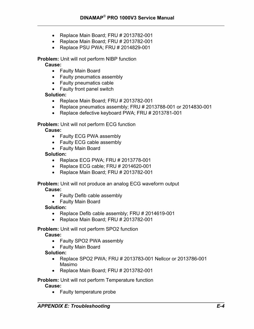
Problem: Unit will not perform SPO2 function
Cause: • Faulty SPO2 PWA assembly • Faulty Main Board
Solution: • Replace SPO2 PWA; FRU # 2013783-001 Nellcor or 2013786-001
Masimo • Replace Main Board; FRU # 2013782-001
Problem: Unit will not perform Temperature function
Cause: • Faulty temperature probe
APPENDIX E: Troubleshooting E-4

DINAMAP® PRO 1000V3 Service Manual
• Faulty temperature probe sensor • Faulty Main Board
Solution: • Replace temperature probe • Replace probe sensor; FRU # 2013777-001 • Replace Main Board; FRU # 2013782-001
Problem: Unit will not print
Cause: • Unit out of paper or paper incorrectly installed • Faulty printer • Faulty Main Board • Faulty PSU PWA
Solution: • Check paper installation • Replace printer; FRU # 2013787-001 • Replace Main Board; FRU # 2013782-001 • Replace PSU PWA; FRU # 2014829-001
Problem: Unit will not generate sound
Cause: • Faulty speaker assembly • Faulty Main Board
Solution: • Replace speaker assembly; FRU # 2014831-001 • Replace Main Board; FRU # 2013782-001
Problem: Unit will not respond to rotary knob
Cause: • Faulty encoder • Faulty Main Board
Solution: • Replace encoder; FRU # 2014712-001 • Replace Main Board; FRU # 2013782-001
Problem: Unit Host Comms not functional
Cause: • Faulty Main Board • Faulty PSU PWA
Solution: • Replace Main Board; FRU # 2013782-001 • Replace PSU PWA; FRU # 2014829-001
APPENDIX E: Troubleshooting E-5

DINAMAP® PRO 1000V3 Service Manual
APPENDIX E: Troubleshooting E-6

DINAMAP® PRO 1000V3 Service Manual
APPENDIX F: Field Replacement Units (FRUs)
APPENDIX F: FRUs F-1

DINAMAP® PRO 1000V3 Service Manual
APPENDIX F: FRUs F-2

DINAMAP® PRO 1000V3 Service Manual
F.1 FRU IDENTIFICATION TABLE The following table offers details of each
of the corresponding bubble numbers that appear on the FRU assembly drawings.
APPENDIX F: FRUs F-3

DINAMAP® PRO 1000V3 Service Manual
APPENDIX F: FRUs F-4


World HeadquartersGE Medical SystemsInformation Technologies, Inc.8200 West Tower AvenueMilwaukee, WI 53223 USATel: +414.355.5000
800.558.5120 (US only)Fax: +414.355.3790
European RepresentativeGE Medical SystemsInformation Technologies GmbHPostfach 60 02 65D-79032 FreiburgGermanyTel: +49 761 45 43 - 0Fax: +49 761 45 43 - 233
Asia RegionGE Medical Systems Asia7-127, Asahigaoka 4-chomeHino-shi, Tokyo 191-8503JapanTel: +81-42-582-6824Fax: +81-42-582-6830
0086
gemedical.com2012820-001 A


![INDEX [frankshospitalworkshop.com]frankshospitalworkshop.com/equipment/documents/.../Guido_Rayos_… · GUIDO RAYOS X, S.A. NESTOMAT 6050 7 MAN-012 Sept.00 Ed. 1 / Rev. 3 (1) HEAT/CALOR](https://img.pdfslide.net/doc/110x75/5eb8907b147cb5163431bf0f/index-fr-fr-guido-rayos-x-sa-nestomat-6050-7-man-012-sept00-ed-1-rev-3.jpg)
![Untitled Document [frankshospitalworkshop.com]frankshospitalworkshop.com/equipment/documents... · Title: Untitled Document Created Date: 1/16/2003 4:35:09 PM](https://img.pdfslide.net/doc/110x75/5fa26dfc1894a959af3321a8/untitled-document-fr-fr-title-untitled-document-created-date-1162003-43509.jpg)


![indeX [frankshospitalworkshop.com]frankshospitalworkshop.com/equipment/documents... · technical speciFications Light Conductor Optics fiber 100% coherent which guarantees the passage](https://img.pdfslide.net/doc/110x75/5e876382b2936843fc63528c/index-fr-fr-technical-specifications-light-conductor-optics-fiber-100-coherent.jpg)