Embed Size (px)
Citation preview

PRO SubWoofers
PRO 104 PRO 124

�
TABLE OF CONTENTS
Congratulations . . . . . . . . . . . . . . . . . . . . . . . . . . . . . . . . . . . . . . . .3Caution . . . . . . . . . . . . . . . . . . . . . . . . . . . . . . . . . . . . . . . . . . . . . .3Specifications . . . . . . . . . . . . . . . . . . . . . . . . . . . . . . . . . . . . . . . . .4Features . . . . . . . . . . . . . . . . . . . . . . . . . . . . . . . . . . . . . . . . . . . . .6Wiring .Configurations . . . . . . . . . . . . . . . . . . . . . . . . . . . . . . . . . . .8Enclosure .Design . . . . . . . . . . . . . . . . . . . . . . . . . . . . . . . . . . . . .17Notes . . . . . . . . . . . . . . . . . . . . . . . . . . . . . . . . . . . . . . . . . . . . . . .�1

3
CONgrATuLATiONS
Thank .you .for .choosing .PrecisionPowerTM .woofers . .Designed .and .engineered .in .the .USA, .this .product .combines .innovative .technology .with . the . finest .materials . to .consistently .deliver .Absolutely State of the Art™ . performance, . sound . quality, . reliability, . and . value . . This .PrecisionPowerTM . product . reflects . our . commitment . to . offer . you .unparalleled . performance . and . quality . for . years . of . dependable .service .and .listening .enjoyment .
Included . in . this . manual . are . a . number . of . different . enclosure .suggestions . .These . are . by . no . means . the . only . enclosures . to . use, .but .they .provide .a .starting .point . .To .determine .the .correct .enclosure .for . your . needs . many . factors . must . be . addressed . (amount . of .power, . vehicle, . placement, . crossovers, . etc .) .Therefore, . as . always .PrecisionPowerTM . recommends . that . your . subwoofer . be . installed .by .an .authorized .PrecisionPowerTM .dealer
CAuTiON
Extended .use .of .a .high .powered .audio .system .may .result .in .hearing .loss . or . damage . . While . PrecisionPowerTM . systems . are . capable .of .“Concert .Level” .volumes .with . incredible .accuracy, . they .are .also .designed .for .you .to .enjoy .at .more .reasonable .levels .all .of .the .sonic .subtleties . created . by . musicians . . Please . observe . all . local . sound .ordinances .

4
SpECiFiCATiONS
Directed .Part .Number �8�06 �8�16
. . . . . . . . . . .Model .Number PRO104 PRO1�4
Thiele/Small parameters
Fs .(free-air .resonance, .Hz) 44 .51 4� .�6
Vas .(equivalent .compliance, .cu . .ft .) 0 .319 0 .656
Vas .(equivalent .compliance, .liters) 9 .03 18 .58
Qms .(Q, .mechanical) 6 .76 7 .68
Qes .(Q, .electrical) 1 .01 1 .03
Qts .(total .driver .Q) 0 .88 0 .91
Re .(DC .resistance, .ohms) 5 .8 5 .8
Z .(nominal .impedance, .ohms) � .x .4 � .x .4
Le .(inductance, .mh) 1 .46 1 .47
Efficiency .(1W .@ .1M, .dB) 80 .87 83 .�3
Xmax .(one .way .linear .excursion, .in .) 0 .91 0 .91
Xmax .(one .way .linear .excursion, .mm) �6 .5 �6 .5
Pe .(continuous .power .handling, .watts) 1000 1000
Peak .power .handling .(music, .watts) �000 �000
Mms .(total .moving .mass, .grams) �18 �60
Cms .(mechanical .compliance, .mm/N) 0 .059 0 .055
Bl .(motor .strength, .Tesla-M) 18 .68 19 .7�
Sd .(effective .radiating .area, .sq . .cm .) 330 .06 491 .03
Sd .(effective .radiating .area, .sq . .in .) 51 .18 76 .11
Frequency .range .(Hz) 44-�50 4�-�50
Energy .Bandwidth .Product .(EBP) 44 41
Driver physical Dimension
Speaker .Outer .Diameter .(inches) 10 .71 1� .44
Speaker .Outer .Diameter .(mm) �7� 316
Mounting .hole .diameter .(inches) 9 .�9 11 .06
Mounting .hole .diameter .(mm) �36 �81
Mounting .depth .(inches) 7 .09 8 .07
Mounting .depth .(mm) 180 �05
Magnet .Weight .(Oz) 155 155
Basket .diameter .(inches) 10 .71 1� .44

5
recommended Enclosures
Typical .sealed .enclosure .(cu . .ft .) 0 .6 0 .9
Enclosure Details
1 . .External .dimensions .calculated .for .3/4” .building .material
� . .Includes .speaker .displacement
3 . .Volumes .given .are .net .tuning .volume
4 . .Enclosures .include .a .minimal .amount .of .damping .material . .Just .enough .ma .terial .to .line .the .inside .of .the .enclosure .is .required . .
Specifications .subject .to .change .without .notice

6
FEATurES
1 . . Woven .Fiberglass .over .a .Rohr .cell .foam .center .– .flat .panel .� . . Tall, .wide, .balanced, .NBR .Foam .(high .density .expanded .
polyester .foam) .surround .for .linear .controlled .long .excursion .using .a .Tri .Radius .symmetrical .edge .design .optimized .on .non-linear .FEA
3 . . Rubber .wrap .around .two .way .mounting .gasket .4 . . Custom .Cast .Aluminum .frame .5 . . Aluminum .flat .panel .to .voice .coil .former .attachment .yoke .6 . . Custom .terminals .and .impedance .jumpers .7 . . Tinsel .leads .woven .to . .single .flat .interlaced .Conex . .spider .8 . . Voice .coil .former .vent .holes . . .Part .of .enhanced .voice .coil .
cooling .system .(forced .convection) .9 . . 10mm .thick .steel .front .gap .plate . . .Part .of . .Mmag .dual .gap .
motor .assembly .10 . . Magnetic .ring .consisting .of .1� .donut .style .ceramic .magnets .
for .front .gap .of .dual .gap .motor . . . .Part .of . .Mmag .dual .gap .motor .assembly . . .Total .magnet .weight .of .items .10 .& .14 .is .155 .oz .

7
11 . . 10mm .thick .steel .rear .gap .plate . . .Part .of .Mmag .dual .gap .motor .assembly .
1� . . 10mm .thick .steel .rear .plat ./ .pole .piece .T .yoke .Part .of . .Mmag .dual .gap .motor .assembly .
13 . . 1 .inch .flared .Vent . . .Part .of .enhanced .voice .coil .cooling .system .(forced .convection) .
14 . . Two .stack .ceramic .magnet .for .rear .gap .Part .of . .Mmag .dual .gap .motor .assembly . . .Total .magnet .weight .of .items .10 .& .14 .is .155 .oz .
15 . . High .temperature .(Polyester .Amide .Amide .Resin .Coated) .Copper .dual .voice .coil . .(�x4 .ohm) . .wound .on .an) .
16 . . Voice .coil .heat .pick-up .and .heat .sink .assembly .that .also .serves .as .a .control .for .flux .and .heat .build .up .and .control .in .the .dual .gap .motor . . .Part .of .enhanced .voice .coil .cooling .system .(forced .convection .– .aluminum .heat .sinking .–shorting .rings .to .reduce .inductive .heating) .
17 . . Aluminum .voice .coil .former .(voice .coil .is .a .3”) .18 . . Vented .spider .ring .and .terminal .block .assembly . . .Integrates .
custom .terminals .and .impedance .jumper .block . . .Venting .in .spider .ring .is .part .of .enhanced .voice .coil .cooling .system .(forced .convection) .
19 . . Vent .holes .in .flat .panel .yoke .assembly . . .Part .of .enhanced .voice .coil .cooling .system .(forced .convection .– .aluminum .heat .sinking .–shorting .rings .to .reduce .inductive .heating) .

8
WiriNg CONFigurATiONS
The .following .illustrations .provide .guidelines .on .properly .connecting .your .PrecisionPowerTM .woofer .to .a .PrecisionPowerTM .amplifier .for .maximum .power .and .performance .using .common .parallel, .and .series/parallel .wiring .configurations
Recommended .Amplifier .PowerContinuous .Power .(RMS) Peak .Power .(watts
1 . .woofer 500 .to .1000 600 .to .�000
� . .woofers 1000 .to .�000 1�00 .to .4000
3 .woofers 1500 .to .3000 1800 .to .6000
4 . .woofers �000 .to .4000 �400 .to .8000
Technical Brief:How .to .properly .wire .a .PPI .woofer .in .parallel .to .a .PPI .amplifier .for .maximum .power .and .performance .
4 oh
m
4 oh
m
+ +
- -
+
-
1. Wire . the . speaker . parallel . by . connection . the . two . + . terminals .together .and .the .two .- .terminals .together .

9
2. Wire .the .positive .(+) .terminals .of .the .speakers .to .the .positive .(+) .terminal .on . the .amplifier . .Wire . the .negative .(-) . terminals .of . the .woofers .to .the .negative .(-) .terminal .on .the .amplifier .
3. .This .wiring .show .the .amplifier .a .� .ohm .load . .
Technical Brief:How .to .properly .wire .a .PPI .woofer . in .series . to .a .PPI .amplifier . for .maximum .power .and .performance .
4 oh
m
4 oh
m
+ +
- -
+
-
1. Wire .the .woofer's .coils .together .in .series .by .wiring .the .positive .of .one .coil .to .ther .negative .of .the .other .coil . .This .is .series .wiring .
.2. Wire . the . two . open . terminals . to . the . amplifier, . positive . terminal .
to . the . amplifier . positive . and . negative . terminal . to . the . amplifier .negative .
.3. . .This .wiring .show .the .amplifier .a .8 .ohm .load .

10
Technical Brief:How .to .properly .wire .a .PPI .woofer .in .parallel .to .a .PPI .amplifier .for .maximum .power .and .performance .
4 oh
m
4 oh
m
+ +
- -
4 oh
m
4 oh
m
+ +
- -
+
-
1. Wire .the .two .speaker's .voice .coil .parallel .by .connection .the .two .+ .terminals .together .and .the .two .- .terminals .together .
2. Wire .the .positive .(+) .terminals .of .the .speakers .to .the .positive .(+) .terminal .on . the .amplifier . .Wire . the .negative .(-) . terminals .of . the .woofers .to .the .negative .(-) .terminal .on .the .amplifier .
3. . .This .wiring .show .the .amplifier .a .1 .ohm .load .

11
Technical Brief:How .to .properly .wire .a .PPI .woofer .in .series/parallel .to .a .PPI .amplifier .for .maximum .power .and .performance .
4 oh
m
4 oh
m
+ +
- -
4 oh
m
4 oh
m
+ +
- -
+
-
1. Connect .each .woofer .in .series .by .connecting .the .negative .(-) .of .the .first .coil .to .the .positive .(+) .terminal .of .the .second .coil .
2. Wire .the .positive .(+) .terminals .of .the .first .coil .of .each .woofer .to .the .positive . (+) . terminal . on . the .amplifier . .Wire . the .negative . (-) .terminal . of . the . second . coil . of . each . woofer . to . the . negative . (-) .terminal .on .the .amplifier .
3. . .This .wiring .show .the .amplifier .a .4 .ohm .load .

1�
Technical Brief:How .to .properly .wire .a .PPI .woofer .in .parallel .to .a .PPI .amplifier .for .maximum .power .and .performance .
4 oh
m
4 oh
m
+ +
- -
4 oh
m
4 oh
m
+ +
- -
4 oh
m
4 oh
m+ +
- -
+
-
1. Connect .each .woofer .in .series .by .connecting .the .negative .(-) .of .the .first .coil .to .the .positive .(+) .terminal .of .the .second .coil .
2. Wire .the .positive .(+) .terminals .of .the .first .coil .of .each .woofer .to .the .positive . (+) . terminal . on . the .amplifier . .Wire . the .negative . (-) .terminal . of . the . second . coil . of . each . woofer . to . the . negative . (-) .terminal .on .the .amplifier .
3. . .This .wiring .show .the .amplifier .a .� .67 .ohm .load .

13
Technical Brief:How .to .properly wire a ppi woofer .in .seriesparallel .to .a .PPI .amplifier .for .maximum .power .and .performance .
4 oh
m
4 oh
m
4 oh
m
4 oh
m
4 oh
m
4 oh
m
4 oh
m
4 oh
m+
-
+ +
- -
+ +
- -
+ +
- -
+ +
- -
1 . . . Connect .each .woofer .in .series by .connecting .the .negative .(-) .of .the .first .coil .to .the .positive .(+) .terminal .of .the .second .coil . .
� . . . Wire . the . positive . (+) . terminals . of . the . first . coil . of . each . woofer .to . the . positive . (+) . terminal . on . the . amplifier . .Wire . the . negative .(-) .terminal .of .the .second .coil .of .each .woofer .to .the .negative .(-) .terminal .on .the .amplifier .
. .3 . . . This .wiring .show .the .amplifier .a .� .ohm .load .

14
The .Pro .subs .also .can .utilize .jumper .settings .rather .than .wiring .each .coil .individually .as .the .above .diagrams .show . .
.By .default .the .jumpers .come .in .the .top .two .spots . .This .would .keep .each .of . the .coils .separate . just .as .a . regular .dual .voice .coil .woofer .operates . . All . of . the . above . diagrams . would . work . fine . when . the .jumpers .are .in .this .position . .
.With .the .jumpers .in .the .bottom .two .it .would .wire .the .coils .in .parallel, .giving .you .a .two .ohm .final .load . .You .would .only .need .to .use .one .set .of . terminals .when .using . the . jumpers . .The .diagram .would . look . like .this . .

15
Technical Brief:How .to .properly wire .a .PPI .woofer .in .parallel .to .a .PPI .amplifier .for .maximum .power .and .performance .
With one jumper in the middle on the bottom row it wires the coils in series.
The diagram would look like this
1 . . . Using .1 .set .of .terminals .wire ther .- .to .the .- .post .of .the .amplifier .and .the .+ .to .the .+ .terminal .of .the .amplifier . .
� . . . This .wiring .show .the .amplifier .a .� .ohm .load .
With .one .jumper .in .the .middle .on .the .bottom .row .it .wires .the .coils .in .series .
The .diagram .would .look .like .this
using the jumper block - both coils in series:With .the .cone .facing .upward .and .the . jumper .block . in . front .of .you, .the . positive . terminal . on . the . terminal . block . on . the . left . side . would .be . positive . and . the . negative . terminal . on . the . right . side . would . be .negative . . .The .negative .on .the .left .terminal .and .the .positive .on .the .right .terminal .are .shorted .together .and .not .used .

16
Technical Brief:How .to .properly .wire .a .PPI .woofer .in .parallel .to .a .PPI .amplifier .for .maximum .power .and .performance .
Note if the sub doesn’t hit or sound right it is probably wired out of phase, switch around the + and – wires.
1 . . . Use . the . + . on . one . of . ther . terminals . to . the . + . of . the . amp . and .the . - .of . the .opposite . terminal . to . the .negative .on . the .amp . .The .subwoofer .would .be .wired .in .series .
� . . . This .wiring .show .the .amplifier .a .8 .ohm .load .
Note .if .the .sub .doesn’t .hit .or .sound .right .it .is .probably .wired .out .of .phase, .switch .around .the .+ .and .– .wires .
+ -
Do .not .use
+ -
Do .not .use
To .amplifier .+ To .amplifier .-
8 .ohm
17
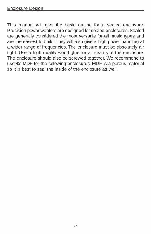
Enclosure .Design
This . manual . will . give . the . basic . outline . for . a . sealed . enclosure . .Precision .power .woofers .are .designed .for .sealed .enclosures . .Sealed .are .generally .considered .the .most .versatile .for .all .music .types .and .are .the .easiest .to .build . .They .will .also .give .a .high .power .handling .at .a .wider .range .of .frequencies . .The .enclosure .must .be .absolutely .air .tight . .Use .a .high .quality .wood .glue .for .all .seams .of . the .enclosure . .The .enclosure .should .also .be .screwed .together . .We .recommend .to .use .¾” .MDF .for .the .following .enclosures . .MDF .is .a .porous .material .so .it .is .best .to .seal .the .inside .of .the .enclosure .as .well . .

18
Pro .104 .Sealed .Enclosure
c
b
—Box Parts—Box Shape – Square Prism1 Top, 1 Bottom depth (c) = 11.5 in. width (b) = 12 in. thickness = 0.75 in.1 Front, 1 Back height (a) = 10.5 in. width (d) = 10.5 in. thickness = 0.75 in.2 Sides height (a) = 10.5 in. depth (c) = 11.5 in. thickness = 0.75 in.
—Driver Mounting— Front
Top &Bottom
a
d
Front &Back
c
Sides

19
Pro .1�4 .Sealed .Enclosure
A
B
C
—External Dimensions—A = 16 in.B = 15 in.C = 13.5 in.—Internal Dimensions—A = 14.5 in.B = 13.5 in.C = 11.75 in.—Wall Thickness—All Sides = 0.75 in.
c
b
—Box Parts—Box Shape – Square Prism1 Top, 1 Bottom depth (c) = 13.25 in. width (b) = 15 in. thickness = 0.75 in.1 Front, 1 Back height (a) = 14.5 in. width (d) = 13.5 in. thickness = 0.75 in.2 Sides height (a) = 14.5 in. depth (c) = 13.25 in. thickness = 0.75 in.
—Driver Mounting— Front
Top &Bottom
a
d
Front &Back
c
Sides

�1
Notes
_______________________________________________________________________________________________________________________________________________________________________________________________________________________________________________________________________________________________________________________________________________________________________________________________________________________________________________________________________________________________________________________________________________________________________________________________________________________________________________________________________________________________________________________________________________________________________________________________________________________________________________________________________________________________________________________________________________________________________________________________________________________________________________________________________________________________________________________________________________________________________________________________________________________________________________________________________________________________________________________________________________________________________________________________________________________________________________________________________________________________________________________________________________________________________________________________________________________________________________________________________________________________________________________________________________________________________________________________________________________________________________________________________________________________________________________________

WarrantyLIMITED ONE-YEAR CONSUMER WARRANTY/
*LIMITED TWO-YEAR CONSUMER WARRANTY FOR AUTHORIZED DIRECTED DEALER
PURCHASE & INSTALLATION
Directed Electronics (herein “Directed”) promises to the original purchaser, to repair or replace with a new or refurbished unit (at Directed’s sole and absolute discretion) this product should it prove to be defective in workmanship or material under normal use, for a period of *two-years from the date of purchase from the authorized Directed dealer PROVIDED the product was purchased and installed by an authorized Directed dealer. During this *two-year period, there will be no charge for the repair or replacement PROVIDED the unit is returned to Directed, shipping prepaid, along with the required proof of installation, the bill of sale or other dated proof of purchase, and the consumer’s contact information. If the unit is installed by anyone other than an authorized Directed dealer, the warranty period will be one-year from the date of purchase. This warranty is non-transferable and does not apply to any unit that has been modified or used in a manner contrary to its intended purpose, and does not cover damage to the unit caused by installation or removal of the unit. During this one-year period, there will be no charge for the repair or replacement PROVIDED the unit is returned to Directed, shipping pre-paid, along with the bill of sale or other dated proof of purchase and the consumer’s contact information. This warranty is void if the product has been damaged by accident or unreasonable use, neglect, improper service or other causes not arising out of defects in materials or construction. This warranty does not cover the elimination of externally generated static or noise, or the correction of antenna problems or weak reception, damage to speakers, accessories, electrical systems, cosmetic damage or damage due to negligence, misuse, failure to follow operating instructions, accidental spills or customer applied cleaners, damage due to environmental causes such as floods, airborne fallout, chemicals, salt, hail, lightning or extreme temperatures, damage due to accidents, road hazards, fire, theft, loss or vandalism, damage due to improper connection to equipment of another manufacturer, modification of existing equipment, or Product which has been opened or tampered for any reason. Units which are found to be damaged by abuse resulting in thermally damaged voice coils are not covered by this warranty but may be replaced at the absolute and sole discretion of Directed. Unit must be returned to Directed, postage pre-paid, with bill of sale or other dated proof of purchase bearing the following information: consumer's name, telephone number, and address, authorized dealer's name and address, and product description. Unit must be returned to the following address: ATTN: WARRANTY DEPARTMENT, Directed Electronics , 1 Viper Way, Vista, CA 92081. Note: This warranty does not cover labor costs for the removal and reinstallation of the unit. IN ORDER FOR THE TWO-YEAR WARRANTY TO BE VALID, YOUR UNIT MUST BE SHIPPED WITH PROOF OF INSTALLATION BY AN AUTHORIZED DIRECTED DEALER. ALL UNITS RECEIVED BY DIRECTED FOR WARRANTY REPAIR WITHOUT PROOF OF DIRECTED DEALER INSTALLATION AND PURCHASE WILL BE COVERED BY THE LIMITED 1 YEAR WARRANTY.
BY PURCHASING THIS PRODUCT, ALL WARRANTIES INCLUDING BUT NOT LIMITED TO EXPRESS WARRANTY, IMPLIED WARRANTY, WARRANTY OF MERCHANTABILITY, FITNESS FOR PARTICULAR PURPOSE, AND WARRANTY OF NON-INFRINGEMENT OF INTELLECTUAL PROPERTY ARE EXPRESSLY EXCLUDED TO THE MAXIMUM EXTENT ALLOWED BY LAW, AND DIRECTED NEITHER ASSUMES NOR AUTHORIZES ANY PERSON TO ASSUME FOR IT ANY LIABILITY IN CONNECTION WITH THE SALE OF THE PRODUCT. DIRECTED HAS ABSOLUTELY NO LIABILITY FOR ANY AND ALL ACTS OF THIRD PARTIES INCLUDING ITS AUTHORIZED DEALERS OR INSTALLERS. IN NO EVENT WILL DIRECTED BE LIABLE FOR ANY INCIDENTAL, SPECIAL OR CONSEQUENTIAL DAMAGES (INCLUDING LOSS OF PROFITS). BY PURCHASING THIS PRODUCT, THE CONSUMER AGREES AND CONSENTS THAT ALL DISPUTES BETWEEN THE CONSUMER AND DIRECTED SHALL BE RESOLVED IN ACCORDANCE WITH CALIFORNIA LAWS IN SAN DIEGO COUNTY, CALIFORNIA. This warranty is only valid for sale of Product within the United States of America. Product sold outside of the United States of America is sold “AS-IS,” and shall have NO WARRANTY, express or implied. Some states do not allow limitation on how long an implied warranty lasts. In such states, the limitation or exclusions of this Limited Warranty may not apply. Some states do not allow the exclusion or limitation of incidental or consequential damages. In such states, the exclusion or limitation of this Limited Warrantymay not apply to you. This Limited Warranty gives you specific legal rights, and you may have other rights which vary from state to state. 920-0033 Rev 02-07
© 2007 Directed Electronics. All rights reserved. G28206.16 01-07