Embed Size (px)
Citation preview

Proactive Context Transfer and Forced Handover inIEEE 802.11 Wireless LAN Based Access Networks∗
Ha Duong Arek Dadej Steven [email protected] [email protected] [email protected]
Institute for Telecommunications Research, University ofSouth Australia, Australia
In recent years, many protocols have been developed to support user mobility in wirelessnetworks, e.g. Mobile IP suite of protocols designed to support IP routing to mobile nodes.However, support for truly seamless mobility requires more than just routing: every serviceassociated with the mobile user needs to be transferred smoothly to the new access network.In this paper, we will concentrate on the problem of transferring service state (context) atboth the link and the IP layers. We propose a method to estimate the best moment in timefor transferring context information associated with the mobile user. As one of key issues inthe proactive context transfer scheme is accuracy of handover prediction, we suggest anddescribe a new concept of Forced Handover that can provide very low handover latency.The simulation results and the following discussions show that our scheme is helpful inensuring seamless mobility, while keeping the number of unnecessary handovers resultingfrom the proactive nature of the scheme at a controllable level.
I. Introduction
The mobility of wireless users has created a numberof technological challenges, especially when a MobileNode (MN) changes the point of attachment to the net-work. In recent years, a great deal of research efforthas been spent on the issue of mobility, and resultedin development of the general framework, as well asspecific mechanisms and protocols supporting mobil-ity. For example, the IETF Mobile IP Working Group(WG) has developed a solution officially namedIPmobility support , and commonly known asMobileIP [4].
Mobile IP and other mobility support protocols areintended to solve the problem of IP routing (i.e. find-ing the IP path) to the MNs. Typically, however,the access network may also need to establish andkeep service state information (service context) nec-essary to process and forward packets in a way thatsuits specific service requirements, for example, Qual-ity of Service (QoS) state or Authentication, Autho-rization and Accounting (AAA) state. Another ex-ample of context information is the header compres-sion state established and maintained between an Ac-cess Router (AR) and the MN to reduce the large IPheader overhead of short (e.g. voice) packets sent overa bandwidth-limited wireless link. To provide truly
∗A part of this work was presented at the 2nd ACM Interna-tional Workshop on Wireless Mobile Application and Services onWLAN Hotspots (WMASH 2004) under the title “Proactive Con-text Transfer in WLAN-based Access Networks”.
seamless mobility for real-time applications, both IPlayer connectivity and the relevant context informa-tion have to be established or re-established as quicklyas possible after a handover. However, the current re-search [7] indicates that it is impossible to re-establishboth IP connectivity and service context within thetime constraints imposed by real-time applicationssuch as Voice over IP. Therefore, Context Transfer(CT) has been suggested as an alternative way ofrestoring the service context at the new access net-work.
As a means for CT, the IETF Seamoby WG iscurrently developing the Context Transfer Protocol(CTP) [8]. The CTP describes a simple way to trans-fer context information from the old AR to the newAR, to enable faster re-establishment of services. TheCTP is expected to save time and bandwidth, and con-sequently to improve handover performance. How-ever, even with CTP, many issues still must be solvedin order to support specific services. For example,as CTP only specifies the transfer procedure betweentwo ARs, it is not clear what CTP can or should doin cases when the service involves a number of othernetwork entities. Unfortunately, most services suchas AAA, QoS, or security, require participation of notonly ARs, but also other network entities (e.g. authen-tication servers, resource managers). Therefore, someadditional time will be required to re-establish servicestate after the new AR receives context informationby means of CTP. This limitation can be considereda result of following a reactive CT approach where
Mobile Computing and Communications Review, Volume 9, Number 3 1

the context transfer takes place immediately after han-dover, and provides a good motivation to examiningthe alternative proactive approach to CT, i.e. trans-ferring the necessary context before the handover isneeded or occurs.
I.A. Related Works on Proactive ContextTransfer
Even though CT can reduce the delay of contextreestablishment, the resulting delay is still a signif-icant component of handover delay. Therefore, re-cently, a number of researchers have become inter-ested in proactive CT. Pagtzis [11] suggested a proac-tive IP mobility model where MN’s IP connectivityand other context are established at the new point ofattachment in advance of the actual handover (transi-tion between points of attachment). The key point inthis model is the Mobility Neighbour Vector (MNV)- Routing Neighbour Vector (RNV) mapping. TheMNV represents a collection of cells within the neigh-bourhood reachable from the current cell; while RNVis a collection of routers associated with MNV. Dis-covery of the MNV-RNV mapping is achieved incre-mentally by means of dynamic learning i.e. MN’shandover transitions between Access Points (AP) andARs. While Pagtzis’ work focused on proactive mo-bility at the IP layer level, Mishra [2] focused onproactive context caching at the link layer level. Inthe link level model, after the MN associates with anAP, the AP will forward MN’s context information toneighbour APs. Each AP learns about its neighboursthrough previous re-associations of MNs.
The shortcoming of the above works is that the au-thors did not consider the waiting time of the trans-ferred context at the new access network. Timing isan important aspect in CT, especially in the case ofQoS context. If QoS context is transferred too earlyin respect to handover, resources held (reserved) inthe neighbouring access networks will be wasted untilthe MN re-establishes IP connectivity at its new pointof attachment. Therefore, it is desirable that contextinformation is transferred as close as possible to thehandover time.
I.B. An Overview of Our Work
In this paper, we propose a proactive scheme for CTthat attempts to estimate the best moment for proac-tive CT. With proactive approach, the typical questionis: when should the proactive context reestablishmentstart? The starting time should be directly related tothe time the handover occurs, which in turn depends
on handover prediction mechanism. In mobile net-works, a handover typically occurs when a new pointof attachment offers a better service (e.g. communica-tions link, error rate) than the current point of attach-ment. Handover prediction techniques try to estimatewhen a better point of attachment will become avail-able. If handover prediction and proactive contextreestablishment are used together, the context reestab-lishment may be a waste if the handover predictionfails. On other hand, it is desirable that the time be-tween the context reestablishment and the actual han-dover is as short as possible; otherwise resources willbe wasted at the new access network. In other words,the proactive CT should start and be completed asclose as possible to the time of actual handover. Theabove requirement has led us to propose a new con-cept of Forced Handover i.e. a handover forced to oc-cur at a “planned” moment. The philosophy of theForced Handover is that instead of guessing the han-dover time, we force the handover at a planned time.With Forced Handover, instead of wasting resourcesin case of handover prediction failure, we may experi-ence unnecessary handovers. However, the number ofunnecessary handovers can be kept at a controllablelevel, as will be shown later in our analysis. At theexpense of some unnecessary handovers, the ForcedHandover will enable proactive CT and reduce han-dover latency.
In short, our contributions in this paper are:
• A new proactive scheme for integration of Mo-bile IP and its enhancements, Context TransferProtocol and Candidate Access Router Discov-ery (CARD) protocol [10].
• Forced Handover as a key component of theproactive scheme.
• Demonstrated feasibility and effectiveness of theproposed scheme in IEEE 802.11 WLAN-basedaccess networks.
As WLANs, particularly IEEE 802.11 are the mostpopular access technology in wireless Internet due tolow deployment cost and hight date rates, in this pa-per we will examine proactive CT and Forced Han-dover in WLAN-based access networks. As part offuture work, we intend to investigate these techniquesin other types of access networks (e.g. cellular net-works).
The rest of the paper is organized as follows. In thenext section, we provide background information in-cluding handover at WLAN MAC layer, the IETF pro-posed Mobile IP standard and its enhancements, CTP
2 Mobile Computing and Communications Review, Volume 9, Number 3

and CARD protocols. Our contributions, proactiveCT and Forced Handover, are described in section III.Then, in the following two sections, we discuss per-formance metrics useful in evaluating our proposedscheme, with the emphasis on imperfect handoversand handover latency reduction. We also present re-sults from the analysis of the proposed scheme (viasimulation), and subsequent discussions. Finally, wemake some concluding remarks and comments on theareas of research intended for future work.
II. Overview of Handover Process inIEEE 802.11 WLAN based AccessNetworks
A handover between points of attachment may occurat the link layer level or at the network layer level.In all cases, the change should be transparent to theuser. In this section, after defining the terminologyused throughout this paper, we provide backgroundon how handovers may be performed in a WLAN-based access networks. This includes a descriptionof the IEEE 802.11 MAC (link layer) handover proce-dure, as well as the key protocols in performing a net-work level (network layer) handover, Mobile IP, Con-text Transfer Protocol and Candidate Access RouterDiscovery Protocol.
II.A. Terminology
In this paper we define the network entities and han-dover concepts as follows:
• Access Point (AP) - A radio transceiver viawhich a MN obtains link layer (Layer 2) connec-tivity to the access network. An AP is typicallya bridge between the wireless link and a wiredlink.
• Access Router (AR)- An IP router residing in anaccess network, connected to one or more APs,and offering IP (Layer 3) connectivity to the MN.
• Inter-AP handover - The process of switching(handing over) from one AP to another. This is aLayer 2 handover - in the IEEE 802.11 standard,this process is calledre-association.
• Inter-AR handover - The process of switchingfrom one AR to another AR, i.e. a Layer 3 han-dover.
Following from these definitions, an inter-AP han-dover will only result in an inter-AR handover whenthe old AP and the new AP are not connected to the
same AR. As an example, Figure 1 illustrates a MNroaming in an area served by AR1 and AR2. The MNencounters an inter-AP handover when it moves fromthe cell served by AP1 to the cell served by AP2. Incontrast, when the MN performs an inter-AP handoverfrom AP2 to AP3, an inter-AR handover from AR1 toAR2 is also performed.
AP1
AR2
Inter-AP handover
Inter-AR handover
Inter-AP handover
Internet
AR1
AP2 AP3 AP4
Figure 1: Inter-AP handovers and Inter-AR han-dovers.
II.B. Inter-AP handovers in 802.11WLANs
The inter-AP handover process in a WLAN is a se-quence of events occurring between APs and MN, andresulting in a switch of physical and link connectiv-ity from one AP to another. In IEEE 802.11, thereare four key components of the handover process: thehandover trigger; AP discovery and selection; (re-)authentication; and (re-)association (Figure 2). Forbrevity, we will discuss the first two components asthey are most directly related to handover perfor-mance improvement offered by our proposed scheme.Readers can refer to the IEEE 802.11 standard [3] fordetails of the two others.
II.B.1. Handover Triggers
In general, handover triggers are obtained from obser-vations that the link with the current AP is deteriorat-ing. These observations could include failed retrans-missions of packets, missing beacons, or degradationof Signal-To-Noise Ratio (SNR) below a threshold. Inaddition, handover triggers may be based on serviceparameters other than link quality. Load-balancingbetween APs is an example. If the current AP is
Mobile Computing and Communications Review, Volume 9, Number 3 3

New AP
Trigger
MN All APs
Probe Request
Probe Reply
Authentication Request
Authentication Reply
Reassociation Request
Reassociation Reply IAPP operation
AP selection
IEEE 802.11i Security Enhancement
1
2
3
4
Probe Request
Probe Reply
Figure 2: Inter-AP handovers process.
highly loaded, while another AP is serving a lighterload, then a handover to the lightly loaded AP maybe triggered. Ideally, a combination of factors wouldbe used to trigger a handover such that a satisfactorylevel of service is maintained in the network. In prac-tice, there are various different implementations, butnearly all include at least some link quality factors intriggering handovers.
II.B.2. AP Discovery
Whenever a handover trigger occurs, the MN startsthe AP discovery process (box 1 in Figure 2) by cy-cling through the possible radio channels in search fora new, more suitable AP. The IEEE 802.11 standard[3] specifies two types of scanning, namely passiveand active. In the passive scanning mode, the MNswitches to a new channel, waits to receive beaconsfor a period of timeTchannel, and then switches tothe next channel. Normally,Tchannel is set slightlygreater than twice the beacon interval (Tbeacon) so thatthe MN can receive two beacons on a channel. Aftercycling through all available channels (possibly sev-eral times), the MN can select a new AP based oninformation gathered from the beacons (discussed be-
low).
In the active scanning mode, the MN follows theabove process of cycling through channels but insteadof waiting for beacons, the MN sends a Probe Requestframe and waits for a Probe Response from an AP.Once a Probe Request has been sent, the MN starts atimer, and if there is no activity on the channel withina given time (TMinChannel), the MN switches to thenext channel. If the channel has activity, the MN waitsuntil time TMaxChannel, processes all received ProbeResponse frames and then scans the next channel. TheMN uses information collected during the scanningprocess to select a new AP.
The selection of an AP to handover to is typicallybased on the same factors as the trigger, i.e. the qualityof service offered by the AP. In most implementations(e.g. [9]), quality of the communication link, i.e. sig-nal strength or signal-to-noise ratio (SNR), is used tomake the handover decision, although in some otherimplementations (e.g. [5]) the current load on the APsis also taken into account.
In both active and passive scanning modes the scan-ning cycle is repeated every Scanning Interval (TSI )until the MN eventually finds a new AP better thanthe current one. As an example, Figure 3 shows thechange in SNR at two APs as measured by a MN(which is moving away from AP1 and toward AP2).In this case, SNR is used as both the trigger for APdiscovery (SNR1 goes below a cell search threshold,SNRCST ) and the criterion for AP selection and han-dover initiation (the SNR of a new AP must be greater,by the threshold∆, than the SNR of the old AP). Atpoint 1, the cell search threshold is satisfied, trigger-ing the AP discovery process. The MN repeats thescanning cycles until it finds that AP2 provides a bet-ter SNR than the current AP by the amount of positivehysteresis∆ (point 4 in Figure 3).
SNR1 SNR2
SNRCST ∆CT ∆
1 2 3 4
Figure 3: SNR change between AP1 and AP2
4 Mobile Computing and Communications Review, Volume 9, Number 3
In summary, the condition for the inter-AP han-dover is as follows
{
SNR1 < SNRCST
SNR2 > SNR1 + ∆(1)
II.C. Inter-AR handovers
Many proposals have been developed to support therouting process during a handover between ARs, withMobile IP [4] being the most prominent approach.Here we will give a brief overview of Mobile IP. Inaddition to routing, support is needed to expedite thediscovery of potential new ARs and transfer servicestate to those ARs selected. Therefore, following theMobile IP overview, we introduce solutions to AR dis-covery and transfer of service state, i.e. the ContextTransfer Protocol and the CARD protocol.
II.C.1. Mobile IP
The main characteristics of Mobile IP1 include trans-parency to applications and transport layer protocols,scalability, and macro mobility. Mobile IP introducestwo new entities into the network, Home Agent (HA)and Foreign Agent (FA). These two entities can resideanywhere within the subnet where they are serving.For simplicity, we assume that they co-locate withARs. Mobile IP includes two main functions, regis-tration and tunnelling. For the purpose of this paper,we will briefly describe the registration procedure asfollows.
Whenever a MN discovers that it is moving into anew subnet, it sends a Registration Request message,which includes the MN home address, care of addressand HA address, to the new FA. The new FA relays themessage to the HA after retrieving information neces-sary for serving the MN in the future. In response tothe Registration Request, the HA will send a Regis-tration Reply to the new FA. In turn, the FA sends theRegistration Reply to the MN to confirm (or reject) theMNs registration at the new FA. Following this regis-tration procedure, all communications to and from theMN go via the new FA.
II.C.2. Context Transfer Protocol
The objective of the Context Transfer Protocol (CTP)[8], developed by the IETF Seamoby Working Group,
1In this paper, we use Mobile IPv4 to demonstrate the fea-sibility of our proposal, but we believe that the proposal isalsoapplicable to Mobile IPv6 (however that is out of the scope ofthepaper). In the remainder of the paper, the term Mobile IP refers toMobile IPv4.
is to transfer the service state between ARs to enableseamless mobility. CTP has a request-response mech-anism for transferring the service state (or context), aswell as mechanisms for triggering the CT and activat-ing the context once at the new AR. The protocol canbe initiated by either MN or AR, depending on theCT trigger. The CT trigger is still an open issue as itdepends on specific link layer technology. As shownlater in section III.C, our proactive scheme will use thecondition from Eq. (3) as the CT trigger. In network-initiated scenarios, if the CT trigger is detected at theold AR, this AR will send the CT Data (CTD) to thenew AR; otherwise the new AR will request the oldAR to transfer context (CT Request). Upon receiv-ing CTD, the new AR optionally may reply back tothe old AR (CTDR - CT Data Reply). In both cases,the MN will send the CT Activation Request (CTAR).In mobile-initiated scenarios, the MN will send theCTAR upon receiving a CT trigger, usually from thelink layer. Then, the new AR can request CT from theold AR.
Several issues arise when applying the CTP to spe-cific services. For example, the CTP is insufficient incase of services involving network entities other thanARs. Intuitively, reestablishment of these serviceswill require more time; hence reactive reestablishmentmay not be well suited to real-time applications. Thislimitation provides a good motivation to consideringan alternative, namely the proactive approach to CT.In this approach, potential ARs for handover have tobe discovered before the proactive CT can be carriedout.
II.C.3. CARD Protocol
The purpose of the Candidate Access Router Dis-covery (CARD) protocol [10], another draft result-ing from the work of the IETF Seamoby WG, is toidentify (discover) the IP addresses of candidate ARs(CARs) for handover, and to discover their capabili-ties. Our proactive scheme will make use of the firstCARD function mentioned above which, by CARDrecommendations, can be implemented in either cen-tralized or decentralized manner. The result of addressmapping is included in the CARD Reply message thatis sent back to the current AR. The reader should referto [10] for more details of the mapping scheme.
As mentioned earlier, three protocols, Mobile IP,CTP and CARD are expected to work together to fa-cilitate seamless handover. Our contribution offers away to combine these three protocols into a proactiveCT scheme. To ensure smooth operation of the proac-tive scheme, we also suggest the concept of Forced
Mobile Computing and Communications Review, Volume 9, Number 3 5

Handover. We will describe these proposals in detailin the next section.
III. Proposed Scheme for ProactiveContext Transfer in Forced Han-dover
In section I, we stated that proactive CT should startand be completed as close as possible to the time ofactual handover. To do this, we propose a method ofestimating the time when the proactive CT should oc-cur (section III.A), as well as the concept of ForcedHandover (section III.B), where we take advantageof a predicted handover at the expense of incurringa small number of unnecessary handovers. In sectionIII.C, we describe the complete proactive process, in-cluding CTP and CARD operations.
III.A. Estimation of Proactive ContextTransfer Time
Assuming CT can be completed within a scanning in-terval, the best time to start the CT is at the scanninginterval closest to (but before) the actual handover.We propose the following procedure to estimate whichscanning interval (or cycle) the CT should start at. Wealso assume that SNR is used for triggering and AP se-lection because of its wide acceptance as a handovercriterion.
When in the cell-search state, after every scanningcycle, the MN estimates the time until handover asfollows
Tuntil handover =∆ − (SNR2 − SNR1)
RSNR2− RSNR1
(2)
whereRSNR1and RSNR2
are rates of SNR changefor signals from the current AP and the scanned APrespectively. These rate values are obtained and up-dated on the basis of SNR measurements performedas part of the current and previous scanning cycles.
If the Tuntil handover is less than or equal to theTSI (point 3 in Figure 3), the current scanningcycle is likely to be the second last (now calledscanning-to-CT), and in the next scanning cycle (nowcalledscanning-to-handover), the handover conditionis likely to be satisfied. In short, the MN identifies thescanning-to-CT by
Tuntil handover≤TSI (3)
To reduce computations, the MN may start to esti-mate theTuntil handover when the following conditionis satisfied
{
SNR1 < SNRCRT
SNR2 > SNR1 + ∆CT(4)
where∆CT is less than∆.∆CT (point 2 in Figure 3) should be selected
such that there is at least one scanning cycle be-fore scanning-to-handover; therefore it can be definedfrom the following formula
∆ − ∆CT
RSNR2max− RSNR1max
= TSI (5)
whereRSNR1maxandRSNR2max
are maximum ratesof SNR change from the current AP and the scannedAP. The rate values of interest can be learnt (esti-mated) from previous measurements, or pre-set.
III.B. Forced Handover
The above technique can produce a good estimate ofthe time for proactive CT (scanning-to-CT) and thetime for handover (scanning-to-handover). This willbe later confirmed by simulation. However, there isnot a 100% guarantee that the handover condition inEq. (1) will be satisfied at the time of scanning-to-handover. One can argue that if the Eq. (1) is not satis-fied at the time of scanning-to-handover, the MN maywait until the next scanning. However, in this case weneed to set up a longer waiting time for the transferredcontext at the new AP (if inter-AP handover) or newAR (if inter-AR handover), and consequently theremay be more resources wasted. We suggest a ForcedHandover, i.e.the MN will make the handover af-ter the scanning-to-handover time is reached, re-gardless of whether the handover condition in Eq.(1) is satisfied or not.The main advantage of ForcedHandover is that the MN knows exactly when the han-dover will happen, and therefore can set up an appro-priate waiting time for the transferred context at thenew access network. The Forced Handover at the linklayer level also allows the MN sufficient time to pre-pare for the IP level handover. For example, the MNmay use the Forced Handover as a trigger to send anAgent Solicitation message [4] to acquire the RouterAdvertisement message [4] from the new FA; there-fore it can reduce the Agent Discovery time (TAD) toas low as one Round Trip Time (RTT) between theMN and the new FA. TheTAD can be further reducedif the MN is able to receive the information neededfor registration with the new FA through the CARDReply message (more details will be given in the nextsubsection). This information enables the MN to cre-ate a Registration Request message [4] in advance andsend it immediately after the MN re-establishes thelink level connection to the new access network. Theshortcoming of Forced Handover is that in some cases,
6 Mobile Computing and Communications Review, Volume 9, Number 3
handover is forced to happen when the handover con-dition Eq. (1) is not yet satisfied; therefore, the num-ber of unnecessary handovers may increase. However,this number can be kept at a reasonably low level asshown in simulation results (see Section V).
III.C. Description of the ProactiveProcess
Now we will describe the proactive scheme for CT.Assume that MN is moving into an area where theSNR from the current AP drops below theSNRCST
(see Figure 3 and box 1 Figure 4):
1. The MN starts a scanning cycle everyTSI sec-onds (i.e. box 2 Figure 4) until the condition Eq.(4) is satisfied.
2. The MN starts estimation of theTuntil handover
and continues scanning cycles until at least oneof the scanned APs satisfiesTuntil handover≤TSI
(box 3 Figure 4).
3. The MN collects L2 addresses of scanned APssatisfying the condition Eq. (3) (now we callthem candidate APs), and sends them to the cur-rent AR via a CARD Request message.
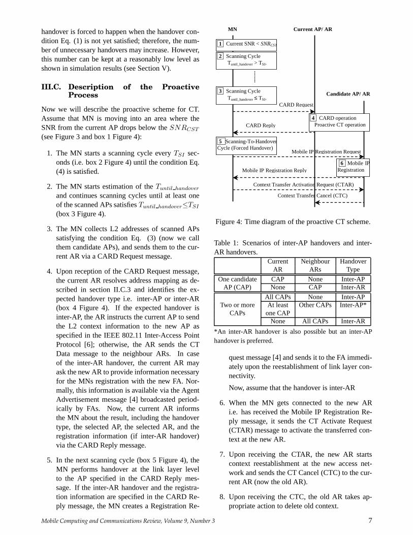
4. Upon reception of the CARD Request message,the current AR resolves address mapping as de-scribed in section II.C.3 and identifies the ex-pected handover type i.e. inter-AP or inter-AR(box 4 Figure 4). If the expected handover isinter-AP, the AR instructs the current AP to sendthe L2 context information to the new AP asspecified in the IEEE 802.11 Inter-Access PointProtocol [6]; otherwise, the AR sends the CTData message to the neighbour ARs. In caseof the inter-AR handover, the current AR mayask the new AR to provide information necessaryfor the MNs registration with the new FA. Nor-mally, this information is available via the AgentAdvertisement message [4] broadcasted period-ically by FAs. Now, the current AR informsthe MN about the result, including the handovertype, the selected AP, the selected AR, and theregistration information (if inter-AR handover)via the CARD Reply message.
5. In the next scanning cycle (box 5 Figure 4), theMN performs handover at the link layer levelto the AP specified in the CARD Reply mes-sage. If the inter-AR handover and the registra-tion information are specified in the CARD Re-ply message, the MN creates a Registration Re-
1 Current SNR < SNRCST
2 Scanning Cycle
Tuntil_handover > TSI.
3 Scanning Cycle Tuntil_handover ≤ TSI.
CARD Request
CARD Reply 4 CARD operation
Proactive CT operation
5 Scanning-To-Handover Cycle (Forced Handover)
MN Current AP/ AR
Candidate AP/ AR
Mobile IP Registration Request
6 Mobile IP Registration Mobile IP Registration Reply
Context Transfer Activation Request (CTAR)
Context Transfer Cancel (CTC)
Figure 4: Time diagram of the proactive CT scheme.
Table 1: Scenarios of inter-AP handovers and inter-AR handovers.
Current Neighbour HandoverAR ARs Type
One candidate CAP None Inter-APAP (CAP) None CAP Inter-AR
All CAPs None Inter-APTwo or more At least Other CAPs Inter-AP*
CAPs one CAPNone All CAPs Inter-AR
*An inter-AR handover is also possible but an inter-APhandover is preferred.
quest message [4] and sends it to the FA immedi-ately upon the reestablishment of link layer con-nectivity.
Now, assume that the handover is inter-AR
6. When the MN gets connected to the new ARi.e. has received the Mobile IP Registration Re-ply message, it sends the CT Activate Request(CTAR) message to activate the transferred con-text at the new AR.
7. Upon receiving the CTAR, the new AR startscontext reestablishment at the new access net-work and sends the CT Cancel (CTC) to the cur-rent AR (now the old AR).
8. Upon receiving the CTC, the old AR takes ap-propriate action to delete old context.
Mobile Computing and Communications Review, Volume 9, Number 3 7

SNR1
SNR2
∆CT ∆
Scanning-to-CT Scanning-to-handover
Figure 5: Time diagram of the premature handover.
SNR1
SNR2
∆CT ∆
Scanning-to-CT Scanning-to-handover Tcompletion
Figure 6: Time diagram of proactive scheme incom-pletion.
In the step 4, there may be a number of differentscenarios, depending on how many APs satisfy thecondition Eq. (3) (i.e. number of candidate APs). Wesummarize these scenarios in Table 1.
IV. Metrics for Performance Evalua-tion
The underlying design trade-off in our proposedscheme is to reduce the handover delay, at the expenseof increasing the number of unnecessary handovers.Intuitively, the handover delay is reduced by discov-ering the potential AP/AR (using CARD) and trans-ferring the necessary context (using CTP) in parallelwith the WLAN handover process. This avoids de-lays due to CT and agent discovery after the WLANhandover process is complete, therefore reducing to-tal handover time. On the other hand, predicting andforcing the handover results in an increase in the num-ber of untimely and unnecessary handovers (due tothe fact that the predictions may be wrong). Suchhandovers lead to a waste of resources (processing,memory) as well as additional handover delays (e.g.a second handover may be needed to compensate forthe first erroneous handover). In order to evaluate ourproactive CT scheme, we attempt to quantify this per-formance trade-off.
In this section, we first look at potential drawbacksof the scheme, namely the waste of resources dueto unnecessary handovers and incomplete CT, andanalyse these effects in further detail, providing ev-idence of the overall benefits of proactive CT andForced Handover. Finally, we discuss how the forcedhandover can reduce handover latency.
IV.A. Unnecessary Handovers
The unnecessary handover can be defined as a han-dover that should not happen (but actually happened
because of forcing). The indication of a possible un-necessary handover is that it is a “premature” han-dover as illustrated in Figure 5. In the prematurehandover, MN estimated thatTuntil handover is lessthan or equal toTSI at the time of the scanning-to-CT, but eventually found that the handover conditionEq. (1) is not satisfied yet at the time of scanning-to-handover. As the MN forces handover to occur any-way, we would like to see whether this Forced Han-dover is necessary or not i.e. whether the MN wouldeventually perform a handover in the near future. Theunnecessary handover happens when the MN movesin such a way that the handover condition Eq. (1) isnever satisfied. For example, the MN changes the di-rection of movement or stops after the scanning-to-CTcycle.
IV.B. Proactive Scheme Completion
Recall from the description of the proactive processin section III.C, that at the time of scanning-to-CT,the MN sends the CARD Request message to triggerproactive CT. After that, the MN waits for the CARDReply message from the current AR as an indicationof proactive scheme completion. If the MN does notreceive this message until the scanning-to-handover(Figure 6), the proactive process can be seen as incom-plete. Incomplete proactive process has the followingeffects:
1. If there is more than one candidate AP, the MNhas to decide which candidate AP to switch toin the scanning-to-handover. The decision wouldbe based on results obtained from the scanning-to-CT (e.g. SNR measurements). As the cur-rent AR is unsure whether the MN received theCARD Reply message, it has to initiate CT to allcandidate APs; therefore there will be resourceswasted at those candidate APs to which the MN
8 Mobile Computing and Communications Review, Volume 9, Number 3

will eventually not connect. To reduce this waste,the new AR or AP, upon reestablishment of con-nectivity with the MN, should notify the candi-date APs to release “unused” context. If thereis only one candidate AP, there is no problemof wasting resources. Therefore, we may be in-terested in finding the probability of having onlyone candidate AP.
2. Upon link reestablishment, the MN has to sendthe Agent Solicitation message in order to reducethe Agent Discovery time (TAD), as it does notknow the expected handover type (i.e. inter-APor inter-AR). If the expected handover is inter-AP, sending of the Agent Solicitation messagewill waste bandwidth.
3. In the case of inter-AR handover,TAD can bereduced only to the RTT between the MN andthe new AR, not to zero, as explained earlier insection III.B.
In summary, in the case of incomplete proactivescheme, there would be wasted effort of CT if thereis more than one candidate AP, wasted bandwidth forsending the Agent Solicitation message, and limitedreduction of Agent Discovery delay.
IV.C. Reduction of Handover Latency
Normally, the handover latency in WLAN-based ac-cess networks includes two elements: latency of linkswitching (or link handover), and latency of networklayer handover. In this section, we explain how theForced Handover can reduce these delays, in particu-lar the Probe delay and Agent Discovery time.
The overview of inter-AP handover in IEEE 802.11WLANs reveals three main factors that contribute tolink handover latency: Probe Delay (TProbeDelay):the time between a MN initiating AP discovery andthe MN selecting a new AP within a scanning cy-cle, Authentication Delay (TAuthentication), and Re-association Delay (TAssociation).
The two factors that contribute to network layerhandover latency are Agent Discovery and Mobile IPRegistration:
1. Agent Discovery (TAD): The time required forthe MN to discover that it has moved to a newsubnet. Like AP discovery,TAD depends oninterval of sending Agent Advertisement mes-sages,TADV interval. As TADV interval is con-strained due to bandwidth consumption, the MNmay require information of inter-AP handover to
speed up discovery by sending the Agent Solici-tation message. Upon reception of this message,the new FA should respond with an Agent Adver-tisement message. Such approach reducesTAD
to the Round Trip Time (RTT) between the MNand the new FA that is normally much smallerthanTADV interval.
2. Registration delay mainly consists of packettransmission delay from the MN to HA via newFA. The processing time at the new FA and HAis quite small, and normally can be ignored.
Experimental results have shown that Probe delay isthe dominating component, accounting for more than90% of link handover delay [1]. The main reason hereis that the MN has to scan every channel from totalN channels (for FCC regulatory domain, applied inNorth American, N = 11), and the total probe delaywould be bounded by
TMinChannelN≤TProbeDelay≤TMaxChannelN (6)
whereTMinChannel and TMaxChannel are two para-meters that determine the duration of scan for eachchannel. To reduceTProbeDelay we need to selectivelyscan some ofN channels (selective scan) instead ofscanning allN channels (full scanning), based on in-formation about channel allocation at neighbour APs.In [2] two algorithms for selective scan were pre-sented. In the Forced Handover, there is no need toscan APs at the handover moment (TProbeDelay = 0)as the scanning process has been completed in previ-ous cycles, and the decision of AP selection has beenmade based on estimation. As authentication contextinformation is to be proactively transferred immedi-ately after the scanning-to-CT cycle, authenticationdelay2 is expected to show a significant reduction.
Forced Handover can also significantly reduceagent discovery timeTAD. Recall from the descrip-tion of the Forced Handover, that the MN can detecta new FA and obtain information needed for registra-tion via the CARD Reply message; henceTAD is re-duced to zero. In the worst case i.e. the MN missedthe CARD Reply message, the MN can still followthe approach of L2 trigger (sending Agent Solicitationmessage). In this case,TAD is equal to RTT betweenthe MN and the FA. We will present numerical resultsof handover latency reduction in section V.B.
2We are currently investigating proactive key distributionforAAA Context Transfer.
Mobile Computing and Communications Review, Volume 9, Number 3 9
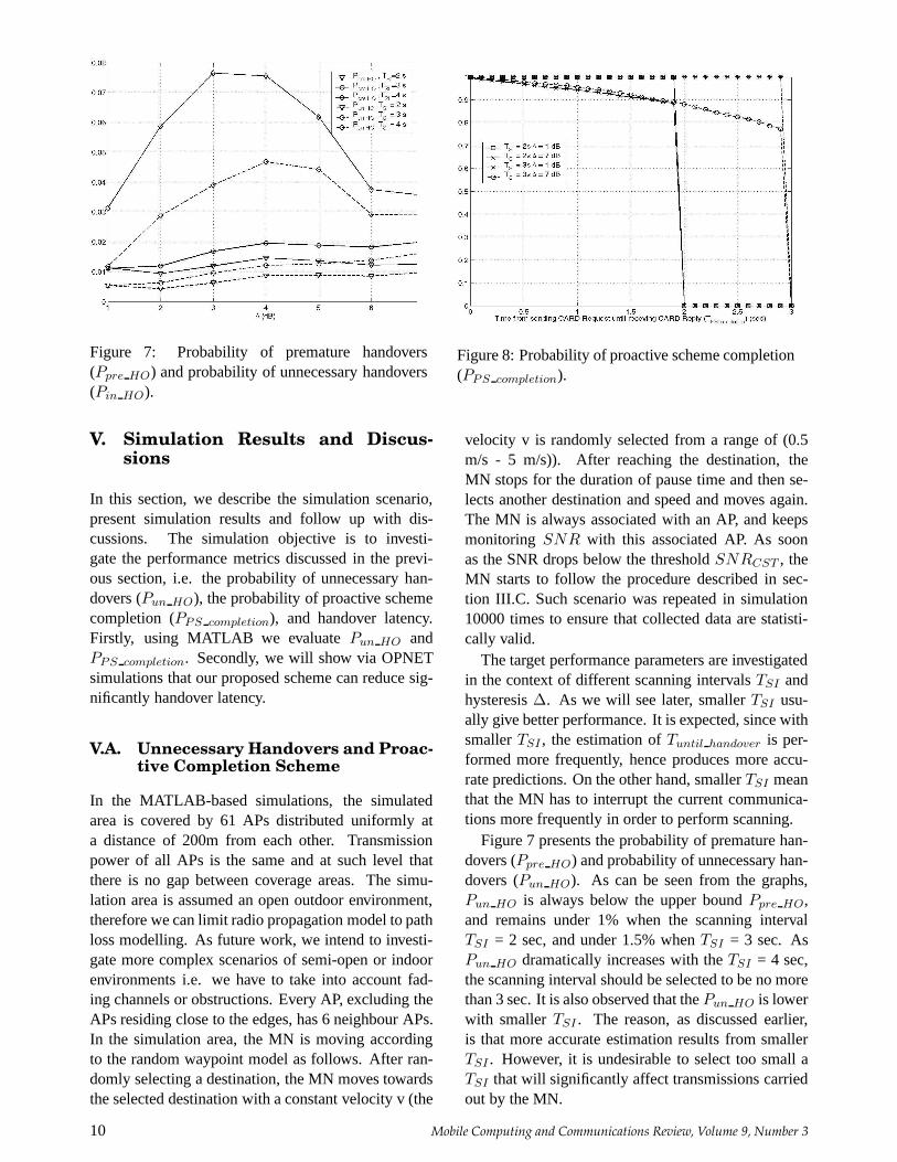
Figure 7: Probability of premature handovers(Ppre HO) and probability of unnecessary handovers(Pin HO).
Figure 8: Probability of proactive scheme completion(PPS completion).
V. Simulation Results and Discus-sions
In this section, we describe the simulation scenario,present simulation results and follow up with dis-cussions. The simulation objective is to investi-gate the performance metrics discussed in the previ-ous section, i.e. the probability of unnecessary han-dovers (Pun HO), the probability of proactive schemecompletion (PPS completion), and handover latency.Firstly, using MATLAB we evaluatePun HO andPPS completion. Secondly, we will show via OPNETsimulations that our proposed scheme can reduce sig-nificantly handover latency.
V.A. Unnecessary Handovers and Proac-tive Completion Scheme
In the MATLAB-based simulations, the simulatedarea is covered by 61 APs distributed uniformly ata distance of 200m from each other. Transmissionpower of all APs is the same and at such level thatthere is no gap between coverage areas. The simu-lation area is assumed an open outdoor environment,therefore we can limit radio propagation model to pathloss modelling. As future work, we intend to investi-gate more complex scenarios of semi-open or indoorenvironments i.e. we have to take into account fad-ing channels or obstructions. Every AP, excluding theAPs residing close to the edges, has 6 neighbour APs.In the simulation area, the MN is moving accordingto the random waypoint model as follows. After ran-domly selecting a destination, the MN moves towardsthe selected destination with a constant velocity v (the
velocity v is randomly selected from a range of (0.5m/s - 5 m/s)). After reaching the destination, theMN stops for the duration of pause time and then se-lects another destination and speed and moves again.The MN is always associated with an AP, and keepsmonitoring SNR with this associated AP. As soonas the SNR drops below the thresholdSNRCST , theMN starts to follow the procedure described in sec-tion III.C. Such scenario was repeated in simulation10000 times to ensure that collected data are statisti-cally valid.
The target performance parameters are investigatedin the context of different scanning intervalsTSI andhysteresis∆. As we will see later, smallerTSI usu-ally give better performance. It is expected, since withsmallerTSI , the estimation ofTuntil handover is per-formed more frequently, hence produces more accu-rate predictions. On the other hand, smallerTSI meanthat the MN has to interrupt the current communica-tions more frequently in order to perform scanning.
Figure 7 presents the probability of premature han-dovers (Ppre HO) and probability of unnecessary han-dovers (Pun HO). As can be seen from the graphs,Pun HO is always below the upper boundPpre HO,and remains under 1% when the scanning intervalTSI = 2 sec, and under 1.5% whenTSI = 3 sec. AsPun HO dramatically increases with theTSI = 4 sec,the scanning interval should be selected to be no morethan 3 sec. It is also observed that thePun HO is lowerwith smallerTSI . The reason, as discussed earlier,is that more accurate estimation results from smallerTSI . However, it is undesirable to select too small aTSI that will significantly affect transmissions carriedout by the MN.
10 Mobile Computing and Communications Review, Volume 9, Number 3

Figure 9: Probability of having one candidate AP(Pone AP ).
Figure 8 depicts thePPS completion when ∆ = 1dB and 7 dB, for two cases of scanning intervalTSI = 2 sec and 3 sec. We also obtained values ofPPS completion with other values of∆ between 1 and7 dB. Those values fall within the two graphs includedin the figures and were not included to improve thereadability of the figure. For small∆ such as 1 dB, thePII PS completion is 100% as long as the completiontime of the proactive schemeTcompletion is less thanTSI . Small∆ implies that handovers occur in the areawell covered by the current AP; therefore the comple-tion of proactive scheme may only be prevented bythe sequence of events whereby by the time the cur-rent AR sends the CARD Reply, the MN has alreadyswitched to the new AP.
Now we turn our attention to the probability of agiven number of candidate APs. For instance, we areinterested in probabilities of having one candidate AP(Pone AP ) (Figure 9).We note that these probabilitiesdepend on positioning of APs in the simulation area.Firstly, we observe that higherPone AP results fromlarger value of hysteresis∆. Larger∆ implies thatthe MN is likely to be close to only one candidate AP.Secondly; we also observe that higherPone AP resultsfrom smallerTSI . However, the differences betweenthe values ofPone AP obtained with differentTSI arenot great, and can be explained by the fact that smallerTSI gives more accurate estimations.
The simulation results and the discussion lead to thefollowing conclusion. With appropriate scanning in-terval TSI , the probability of unnecessary handoverscan be kept as low as 1% or 1.5%. At the expenseof some waste of resources resulting from the un-necessary handovers, the remaining majority of han-
dovers can be very accurately predicted; therefore, theMN has sufficient time to prepare for the handover.The results also reveal that the main factor prevent-ing the completion of proactive scheme is switchingto another AP too early, i.e. situation arising whenthe scanning intervalTSI is too short. In the sim-ulations, theTSI was selected from the range 2 - 3s, and we believe that the proactive scheme can becompleted within such scanning interval. Even whenthe proactive scheme fails to complete, i.e. when theMN is unable to receive the CARD Reply message,the proactive scheme still derives benefits, as con-text data is transferred to candidate APs and ARs.The disadvantage of not being able to complete theproactive scheme, as mentioned in the previous sub-section, is that the MN does not know the expectedhandover type, therefore, there would be wasted band-width for sending the Agent Solicitation message, andlimited reduction of Agent Discovery delay. In thecase of having more than one candidate AP, some ef-forts to transfer context data to candidate APs wouldbe wasted.
However, the second problem is insignificant be-cause of the high probability of having one candidateAP (Pone AP ). In the case of having one candidateAP, the MN still knows the AP to switch to despitemissing the CARD Reply message. However, afterre-association, the MN will still need to send an AgentSolicitation message to discover whether it has movedto a new subnet.
V.B. Handover Latency Reduction
We have used OPNET (www.opnet.com) with WLANMAC and Mobile IP models from the OPNET libraryfor our simulation. We have added active scan andForced Handover features as they were not imple-mented in the original OPNET WLAN MAC model.The modification also includes making informationabout Forced Handover at the WLAN MAC layeravailable to the Mobile IP module. Table 2 lists theparameter values used in the simulation. These arebased on Cisco 340 WLAN card specifications.
Table 2: Simulation Parameters
Layer Parameters Value
Number of Channels 11Beacon Interval (Tbeacon) 0.1 sec
Wlan MAC Channel Time 0.25 secMin Channel Time (TMinChannel) 0.017 secMax Channel Time (TMaxChannel) 0.038 sec
Mobile IP Agent Advertisement Interval 3 sec
Mobile Computing and Communications Review, Volume 9, Number 3 11

Probe
Passive &Full
Passive & Selective Scan
Active &Full
Active & Selective Scan
0.5 sec
0.1 sec 0.2 sec
0.076 sec
Figure 10: Probe delay in various types of scanning.
Agent Discovery Delay
Forced Handover & Incomplete
Proactive CT
Forced Handover & Complete Proactive CT
1.6 sec
0.002 sec 0 sec
No Forced Handover & No Proactive
CT
Figure 11: Comparison of Agent Discovery delays.
Probe delay was measured in scenarios of variousscanning types, namely Passive & Full Scan, Passive& Selective Scan, Active & Full Scan and Active &Selective Scan. Typical results are presented in Fig-ure 10. The number of channels in full scan is 11(FCC Regulatory Domain of North America), whilewith selective scan, we assume that the MN just scansnon-overlapping channels (3 channels). As the MNcontinuously monitors its current channel, the numberof channels to be scanned in full mode and selectivemode are 10 and 2 respectively. From the graph, it isquite clear that having knowledge of channel alloca-tion, and therefore being able to scan selectively, canreduce significantly Probe delay in both passive andactive modes. Active scan further reduces delay, butat the same time consumes more bandwidth becauseof Probe Request and Probe Reply frames.
Figure 11 presents results that confirm what we dis-cussed early in section IV.C. Forced Handover can re-duce significantly Agent Discovery delay, potentiallyto zero. Even in the case of incomplete proactive CT,there is still significant reduction.
Finally, we show results for overall handover la-tency (Table 3) in some typical scenarios as follows:Active & Full Scan, Non-Forced Handover (S1), Ac-tive & Selective Scan, Forced Handover, IncompleteProactive CT (S2), and Active & Selective Scan,Forced Handover, Complete Proactive CT (S3).
It is noted that the Agent Advertisement Interval
Table 3: Handover Latency ComponentsS1 S2 S3
TProbeDelay 212 ms 0 ms 0 msTAuthentication 41 ms 41 ms 0 msTAssociation 21 ms 21 ms 21 ms
TAD 500 ms 20 ms 0 msTRegistration 100 ms 100 ms 100 ms
Overall 847 ms 182 ms 121 ms
(TADV interval) is reduced down to 1 sec, so that av-erage Agent Discovery delay is equal to half of theTADV interval i.e. 500 ms. However, it is still a sig-nificant delay, and can be reduced further by applyingForced Handover (scenarios S2 and S3).
VI. Conclusion and Future Work
In this paper, we presented a simple scheme for proac-tive CT with a new concept of Forced Handover inWLAN-based access networks. Based on observationof SNR changes, the proposed scheme predicts thebest moment in time to perform the CT. In our scheme,the MN is forced to carry out a handover. As the han-dover is forced to happen at a “planned” moment intime, the network can prepare for such event by se-lecting the best AP and AR, and transferring servicecontext information between APs and ARs; thereforethe scheme facilitates seamless mobility. Thanks toproactive CT and Forced Handover scheme, the MNcan significantly reduce Probe delay, authenticationdelay, and Agent Discovery delay; hence improve thehandover latency. The improvement is achieved at theexpense of small increase in the number of unneces-sary handovers; this however can be kept at a reason-ably low level by appropriate selection of scanning in-terval.
We intend to carry the research described in thepaper further. Firstly, we intend to verify the proac-tive scheme for other simulation scenarios, i.e. char-acterised by different AP distributions and mobilitymodels. Secondly, as pointed out in the discussion,the scanning interval is open to optimisation: lowerTSI gives better performance of the proposed scheme,but affects (interrupts) the user communications more.Therefore, we need to investigate optimisation ofTSI .One approach may be to use an adaptive scanninginterval. For example, initiallyTSI can be selectedlarge, and then be reduced adaptively as the MN ap-proaches handover.
12 Mobile Computing and Communications Review, Volume 9, Number 3

References
[1] A. Mishra, M. Shin, and W. Arbaugh, An Em-pirical Analysis of the IEEE 802.11 MAC LayerHandoff Process,ACM Computer Comm. Re-view, vol. 33. no. 2, pp. 93-102.
[2] A. Mishra, M. Shin, and W. Arbaugh, ContextCaching using Neighbour Graphs for Fast Hand-offs in Wireless Networks, University of Mary-land, Technical Report CS-TR-4477, 2003.
[3] ANSI/IEEE Standard 802.11, Part 11: WirelessLAN Medium Access Control (MAC) and Phys-ical Layer (PHY) Specifications, 1999 Edition.
[4] C. Perkins (editor), IP Mobility Support forIPv4, RFC 2002, IETF, January 2002.
[5] Cisco Systems Inc., Cisco AVVID WirelessLAN Design: Solution Reference Network De-sign, 2003.
[6] IEEE, Recommended Practice for Multi-Vendor Access Point Interoperability via anInter-Access Point Protocol Across DistributionSystems Supporting IEEE 802.11 Operation,IEEE Draft 802.11f/D5, Jan 2003.
[7] J. Kempf (editor), Problem Description: Rea-sons for performing Context Transfers betweennodes in an IP access network, RFC 3374, Sept2002
[8] J. Loughney (editor) et al., Context TransferProtocol, Internet draft (draft-ietf-seamoby-ctp-08.txt, work in progress), IETF, Jan 2004.
[9] Lucent Technologies Inc., Roaming with Wave-LAN/IEEE 802.11, Tech. Rep. WaveLAN Tech-nical Bulletin 021/A, Dec 1998.
[10] M. Liebsch, A. Singh, et al., CandidateAccess Router Discovery, Internet draft(draft-ietf-seamoby-card-protocol-05.txt, workin progress), IETF, Nov 2003.
[11] T. Pagtzis, P. Kristein, S. Hailes and H. Afifi,Proactive seamless mobility management for fu-ture IP radio access networks,Computer Comm.,vol. 26, pp. 1975-1989, 2003.
Mobile Computing and Communications Review, Volume 9, Number 3 13