Embed Size (px)
Citation preview
Probabilistic Models for Damage and Self-Repair in DNA Self-Assembly
U. Majumder*
* Department of Computer Science, Duke University, Durham NC, USA, [email protected]
ABSTRACT
Since its inception, the focus of DNA self-assemblybased nanostructures has mostly been on one-time as-sembly. However, DNA nanostructures are very fragileand prone to damage. Knowing the extent of damagethat can occur under various physical conditions canbe useful in making robust designs for self-assemblednanostructures. Thus in this paper, we present sim-ple models for estimating the extent of damage in DNAnanostructures due to various external forces. We notethat these models have not been validated against ex-perimental data and are only meant to serve as a ba-sis for designing DNA nanostructures that are robustto external damage. We conclude with a discussion oncomputing the probability of repair of a damaged nanos-tructure.
Keywords: dna, self-assembly, damage, self-repair,probability
1 Introduction
DNA self-assembly is an autonomous phenomenonwhere components (single strands or DNA “tiles”1) or-ganize themselves into stable superstructures. In recentyears, DNA based self-assembled nanostructures havegone from conceptual design to experimental reality [2].They can, however, be very fragile. For instance, ob-serve the DNA nanotube in Figure 1 which has beenpartially opened up by an AFM tip during imaging.
Winfree [1] briefly investigated if a hole in a DNAlattice will repair correctly in a kinetic simulation model.However, to the best of our knowledge, there has been nowork on either modeling the extent of damage in DNAnanostructures or any experimental measurement of it.Short of an experimental demonstration, we felt that arealistic model for lattice damage and self-repair wouldenable us to better evaluate the current designs for self-repairing tile set. We study the extent of damage due toexternal mechanical forces as well as intense radiation.Furthermore, we compute the probability of self-repairat equilibrium.
1DNA tiles are made of several individual DNA strands withsingle strand overhangs (also called “sticky ends”) that allow themto assemble into a lattice.
Figure 1: Damage in DNA nanostructures: broken DNAnanotubes due to repeated AFM scanning.
2 Mechanical Damage Model
Suppose an AFM tip strikes a tile on a lattice com-posed of several DNA tiles. If we assume that our lat-tice is a rigid surface then the effect of the hitting forceon a neighboring tile can be modeled as a function ofits distance from the source of the impact [3]. In thismodel, the probability that a tile will fall off is givenby the probability that a shock wave from the hittingforce propagates to this tile along some path (Proba-bilistic Damage Model: see Section 2.1). However, if weassume that the lattice is flexible, we can use a massspring model for the lattice and hence calculate the ef-fect of the hitting force on the lattice [5] (Flexible Lat-tice Model: see Section 2.2). One important observationthat we should make here is that we do not know yetwhether these models are appropriate, since they havenot been verified experimentally.
2.1 Probabilistic Damage Model
We assume that the force F1 on a tile located ata distance of r from the tile receiving the impulse isproportional to 1√
r[3]. In our model, r is the Manhattan
distance of the tile under consideration from the sourceof the impact. F2 is the resistive force from the stickyend connections of the tiles. For simplicity, we assumeF2 to be the same for all the tiles. For any tile withF1 > F2, the probability that a tile gets knocked off thelattice is greater than zero so long as the shock wavehas reached it from the origin of damage. To estimatethe fraction of the lattice damaged, we first compute theprobability of a damage path of length i. A damage pathis defined as a path that originates in the tile which is
NSTI-Nanotech 2008, www.nsti.org, ISBN 978-1-4200-8505-1 Vol. 3 705
do Ta,b =Dequeue(Q, Ta,b)For each neighbor Tk,l of Ta,b and color[Tk,l] = white
color[Tk,l] = gray
Compute extended length da,b,k,l =√
|va,b∆t|2 + (l0)2
Enqueue(Q, Tk,l)color[Ta,b] = blackIf mink,l{da,b,k,l} >= dthres
m = m + 1Remove Ta,b
elseCompute va,b = va,b + (F inta,b,k,l−αva,b)∆t
µ
For each neighbor Tk,l of Ta,b and color[Tk,l] = grayCompute F inta,b,k,l = K[da,b,k,l − l0]Compute velocity vk,l of each neighbor Tk,l as vk,l = vk,l +
(Finta,b,k,l−αvk,l)∆tµ
τ = τ + ∆treturn m
O
S2
S3
S4 S5 S6
S1Origin ofDamage
This tile doesnot get knockedoff. Hence shockwave terminateshere
Wave propagation)Damage Path(Instance of Shock
(a)
0.4
60
0.2
0
4020
1
100
0.8
80
0.6
p vs l (a)
Fig. 6. (a)Instance of shock wave propagation and creation of damage path,(b)Estimation of p
Damage of a Lattice with Rigid Support due to a Mechanical Impulse
Simulation Results Based on equation 1 and 2, we can solve for p and as the plotin figure6(b) reveals that the value of p stabilizes to 0.7316 beyond a relativehitting force of 10. Even the drop from an initial value of 0.87 to 0.75 occursbefore the relative hitting force even reach a value of 5. So for all practicalpurposes we consider the value of p to be 0.73. Note that l is determined by thedistance where F1 and F2 equalize. In essence, if F1 = c√
r, where c is a constant,
then l = ( cF2
)2. So l is a measure of the relative hitting force and we will addressit the same in all our plots.
A simulation snapshot for damage by an AFM tip in the lattice is shown inFigure 7a. We study the effect of relative hitting force on the lattice in isolation.Since the probability model is pseudo-geometric in nature, so the amount of ac-tual damage reaches a constant value beyond a value of 10 for the former[Figure
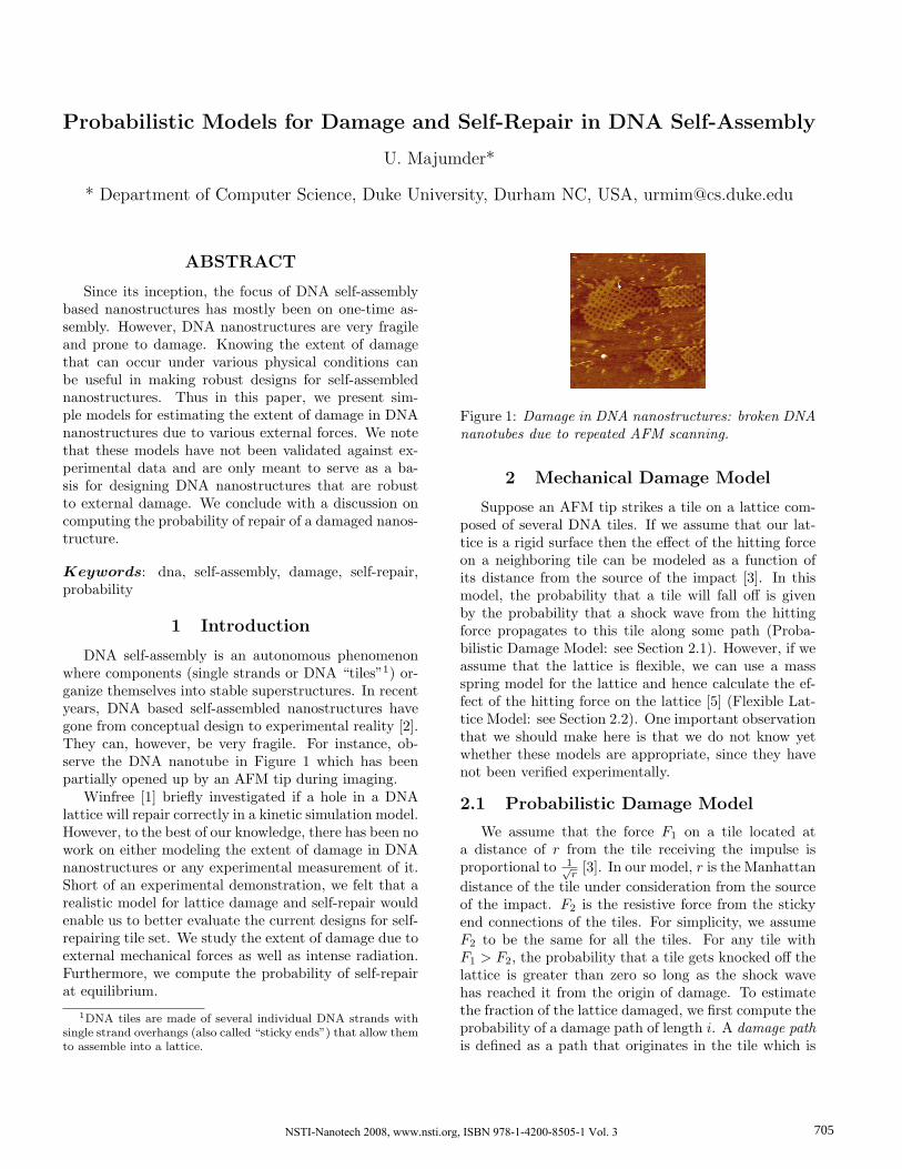
Figure 2: (a)Instance of shock wave propagation andcreation of damage path, (b)Estimation of p
directly hit by the tip (say O) and meanders outwardsthrough its successors < S1, S2, S3, . . . Si−1 > and stopsat Si. In the damage path each tile O,S1, S2, S3, . . . Si−1
is knocked off the lattice except for Si [Figure2(a)]. Letus denote the probability of the damage path that stopsat Si by P (i). Observe that Si is located at a Manhattandistance of i from O. Since F1 is proportional to 1√
i, the
probability that a tile will fall off, given that at leastone of its neighbors is already knocked off, is given byp√i
where p (0 < p < 1) is the normalization factor andcan be evaluated from the probability distribution for adamage path. Then,
P (i) =pi
(√
i− 1)!(1− p√
i) (1)
This is because each tile on this path falls with a prob-ability p√
jwhere j = 1, 2, . . . , i− 1 and the shock wave
stops at Si with probability (1− p√i). Furthermore, P (i)
is a probability mass function and hence, if the maxi-mum length of our damage paths is restricted to l wehave
l∑i=1
P (i) = 1 (2)
Now we can estimate the expected fractional damagesize D(n, l) for a lattice L with n tiles, by summingthe probabilities of a damage path from O to each Si
(maximum damage path length being l) in the lattice.For ease of computation, we achieve this by calculatingthe expected number of tiles knocked off at a Manhattandistance of i from O, ∀i, 1 . . . l.
D(n, l) =(1− p) +
∑li=1 4i× P (i)n
(3)
The first term accounts for the event when the damagepath probabilistically stops at O and 4i is the numberof tiles located at a Manhattan distance i from O.
Simulation Results Based on equation 1 and 2, wecan solve for p analytically. However, for large systems,
7b]. We also compared the average fractional damage size from several simu-lation runs with the expected damage size as estimated from the probabilisticmodel as a function of relative hitting force and lattice size. They seem to agreewell, as is evident from Figure 7c. The verification of the model by comparisonswith experimental data is yet to be done.
(a) (b) (c)
Fig. 7. a)Snapshot of a computer simulation of a damage(red region) by an AFM tip ina rectangular lattice(white region), b)Plot of Actual Damage vs relative hitting force ofthe AFM. The plot reveals the pseudo-geometric nature of the probability distributionof damage, c)Plot of percentage damage as a function of lattice size and relative hittingforce.
A.2 Physical Implementation of RXOR Tiling with DNA Tiles
Experimental Protocols Complex design, sample preparation, and stepwiseassembly: The design of cross-tiles was based on the structure of immobile 4-arm branched junctions. The subsequence used for all bulged loops was four Ts,TTTT. Sequences were designed to minimize the chance of undesired comple-mentary association and sequence symmetry[28]. Synthetic oligonucleotides werepurchased from Integrated DNA Technologies (Coralville, IA) and purified bypolyacrylamide gel electrophoresis (PAGE). Complexes were formed by mixinga stoichiometric quantity of each strand in physiological buffer, 1 × TAEMg2+
(40 mM Tri acetate (pH 8.0), 2 mM EDTA, and 12.5 mM magnesium acetate).The final concentration of DNA was between 0.125 and 1.0µM. For the first stephigh-temperature annealing of unit tiles, equimolar mixtures of strands werecooled slowly from 95◦C to 20◦C by placing the tubes in 2 L of boiled water ina styrofoam box for at least 40 hours to facilitate hybridization. For the secondstep low-temperature annealing, DNA tiles mixtures were cooled slowly from42◦C to 20◦C by placing the tubes in 1 L of water at room temperature forabout 4 hours. After each step of annealing, samples were incubated overnightat 4◦C before AFM imaging.
Streptavidin attachment: After 2nd-step DNA RXOR assembly, add strep-tavidin purchased from Rockland (www.rockland-inc.com, code no: S000 − 01,Lot no: 12088) of same volume of equal concentration of biotin in annealedDNA sample. Leave it an hour at room temperature, and then incubate 4◦C forovernight before AFM experiment.
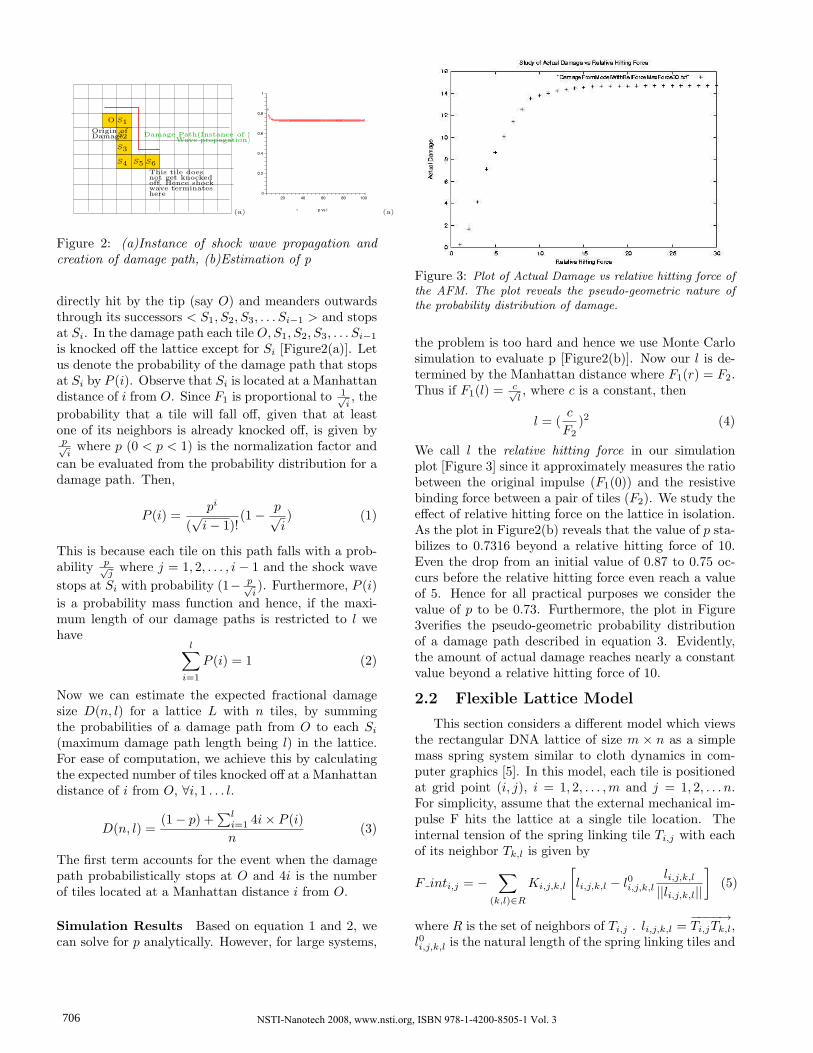
Figure 3: Plot of Actual Damage vs relative hitting force ofthe AFM. The plot reveals the pseudo-geometric nature ofthe probability distribution of damage.
the problem is too hard and hence we use Monte Carlosimulation to evaluate p [Figure2(b)]. Now our l is de-termined by the Manhattan distance where F1(r) = F2.Thus if F1(l) = c√
l, where c is a constant, then
l = (c
F2)2 (4)
We call l the relative hitting force in our simulationplot [Figure 3] since it approximately measures the ratiobetween the original impulse (F1(0)) and the resistivebinding force between a pair of tiles (F2). We study theeffect of relative hitting force on the lattice in isolation.As the plot in Figure2(b) reveals that the value of p sta-bilizes to 0.7316 beyond a relative hitting force of 10.Even the drop from an initial value of 0.87 to 0.75 oc-curs before the relative hitting force even reach a valueof 5. Hence for all practical purposes we consider thevalue of p to be 0.73. Furthermore, the plot in Figure3verifies the pseudo-geometric probability distributionof a damage path described in equation 3. Evidently,the amount of actual damage reaches nearly a constantvalue beyond a relative hitting force of 10.
2.2 Flexible Lattice Model
This section considers a different model which viewsthe rectangular DNA lattice of size m × n as a simplemass spring system similar to cloth dynamics in com-puter graphics [5]. In this model, each tile is positionedat grid point (i, j), i = 1, 2, . . . ,m and j = 1, 2, . . . n.For simplicity, assume that the external mechanical im-pulse F hits the lattice at a single tile location. Theinternal tension of the spring linking tile Ti,j with eachof its neighbor Tk,l is given by
F inti,j = −∑
(k,l)∈R
Ki,j,k,l
[li,j,k,l − l0i,j,k,l
li,j,k,l
||li,j,k,l||
](5)
where R is the set of neighbors of Ti,j . li,j,k,l =−−−−→Ti,jTk,l,
l0i,j,k,l is the natural length of the spring linking tiles and
NSTI-Nanotech 2008, www.nsti.org, ISBN 978-1-4200-8505-1 Vol. 3706
Ki,j,k,l is the stiffness of that spring. With DNA theactual value of Ki,j,k,l is dependent on the type of basesthat are involved in the sticky ends for the pair of tiles.We make some simplifying assumptions: the stiffness Kand the unextended spring length l0 are the same forevery pair of adjacent tiles and known to us a priori forthe purposes of simulation.
2.3 Simulation Algorithm
Since it is difficult to obtain a closed form solutionfor the expected number of tiles that are knocked offthe lattice because of the impulse, we outline a simplesimulation algorithm for estimating the number of tilesremoved when an impulse hits the lattice. We assumethat the lattice is a connected graph where the state ofthe tiles is updated every ∆t time. To that extent, westart a breadth first search from the tile receiving theoriginal impulse.
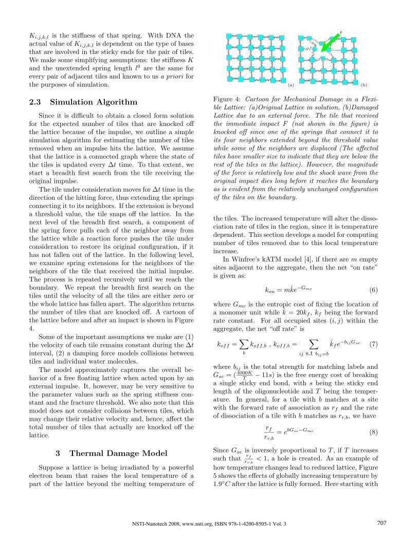
The tile under consideration moves for ∆t time in thedirection of the hitting force, thus extending the springsconnecting it to its neighbors. If the extension is beyonda threshold value, the tile snaps off the lattice. In thenext level of the breadth first search, a component ofthe spring force pulls each of the neighbor away fromthe lattice while a reaction force pushes the tile underconsideration to restore its original configuration, if ithas not fallen out of the lattice. In the following level,we examine spring extensions for the neighbors of theneighbors of the tile that received the initial impulse.The process is repeated recursively until we reach theboundary. We repeat the breadth first search on thetiles until the velocity of all the tiles are either zero orthe whole lattice has fallen apart. The algorithm returnsthe number of tiles that are knocked off. A cartoon ofthe lattice before and after an impact is shown in Figure4.
Some of the important assumptions we make are (1)the velocity of each tile remains constant during the ∆tinterval, (2) a damping force models collisions betweentiles and individual water molecules.
The model approximately captures the overall be-havior of a free floating lattice when acted upon by anexternal impulse. It, however, may be very sensitive tothe parameter values such as the spring stiffness con-stant and the fracture threshold. We also note that thismodel does not consider collisions between tiles, whichmay change their relative velocity and, hence, affect thetotal number of tiles that actually are knocked off thelattice.
3 Thermal Damage Model
Suppose a lattice is being irradiated by a powerfulelectron beam that raises the local temperature of apart of the lattice beyond the melting temperature of
(a)
F
(b)
Figure 4: Cartoon for Mechanical Damage in a Flexi-ble Lattice: (a)Original Lattice in solution, (b)DamagedLattice due to an external force. The tile that receivedthe immediate impact F (not shown in the figure) isknocked off since one of the springs that connect it toits four neighbors extended beyond the threshold valuewhile some of the neighbors are displaced (The affectedtiles have smaller size to indicate that they are below therest of the tiles in the lattice). However, the magnitudeof the force is relatively low and the shock wave from theoriginal impact dies long before it reaches the boundaryas is evident from the relatively unchanged configurationof the tiles on the boundary.
the tiles. The increased temperature will alter the disso-ciation rate of tiles in the region, since it is temperaturedependent. This section develops a model for computingnumber of tiles removed due to this local temperatureincrease.
In Winfree’s kATM model [4], if there are m emptysites adjacent to the aggregate, then the net “on rate”is given as:
kon = mk̂e−Gmc (6)
where Gmc is the entropic cost of fixing the location ofa monomer unit while k̂ = 20kf , kf being the forwardrate constant. For all occupied sites (i, j) within theaggregate, the net “off rate” is
koff =∑
b
koff,b , koff,b =∑
ij s.t bij=b
k̂fe−bijGse (7)
where bij is the total strength for matching labels andGse = ( 4000K
T − 11s) is the free energy cost of breakinga single sticky end bond, with s being the sticky endlength of the oligonucleotide and T being the temper-ature. In general, for a tile with b matches at a sitewith the forward rate of association as rf and the rateof dissociation of a tile with b matches as rr,b, we have
rf
rr,b= ebGse−Gmc (8)
Since Gse is inversely proportional to T , if T increasessuch that rf
rr,b< 1, a hole is created. As an example of
how temperature changes lead to reduced lattice, Figure5 shows the effects of globally increasing temperature by1.9◦C after the lattice is fully formed. Here starting with
NSTI-Nanotech 2008, www.nsti.org, ISBN 978-1-4200-8505-1 Vol. 3 707

(a) (b)
Figure 5: a) Original Lattice, (b) Damaged Lattice dueto increased temperature
a Sierpinski Triangle patterned lattice with 62992 tilesassembled at a temperature of 35.969◦C with Gmc = 19and Gse = 9.7, when heated to 37.892◦C (Gmc = 19,Gse = 9.3) for 2× 10⁵ sec reduces to 34585 tiles.
Although rf
rr,b< 1 gives us the condition for damage,
we are more interested in designing a concrete model tocompute the extent of damage. For this purpose we firstcompute the net rate of both binding and dissociationevents kany as
kany = kon + koff . (9)
In equilibrium, all the rates stabilize and the probabil-ity of any event E occurring is given by a Poisson dis-tribution. Furthermore, the probability of an off eventO happening (given that some event has happened), isgiven by O ∼ Binomial(N, koff ) where N is the totalnumber of events. If n is the size of the damage, we cancompute the probability P (O = n|E = i) of a hole ofsize n, given that a total of i events has occurred. Thenthe probability of dissociating n tiles is P (O = n) where
P (O = n) =∞∑
i=0
P (O = n|E = i)P (E = i) (10)
and the expected size of the damage in that case is
E(O) =M∑
j=0
jP (O = j) (11)
where M is the size of the initial aggregate. This equa-tion is not easy to solve analytically but we can obtainan estimate for E(O) with Monte Carlo integration. Amore accurate estimate can be obtained if we do not as-sume that the rates kon or koff to be constant. Accord-ing to kTAM, these rates vary with number of emptysites, concentration and total number of bonds whichchange as events occur.
4 Self-repair Model
Given a damage model, it is also useful to estimatethe likelihood of the lattice reconstructing itself, a phe-nomenon we call self-healing. This can also be modeled
probabilistically. We estimate the probability of self-repair using techniques from Ref. [4]. We use the samenotation as in Section 3.
Suppose an error-free lattice has a hole of size n torepair. We assume that self-healing is error-free too.Then using the principles of detailed balance, at equi-librium, it has been shown in Ref. [4] that an aggregateA formed by the addition of any sequence of n tilesT1, T2, . . . , Tn with a total strength bA =
∑ni=1 bi. will
obey the following equation:
[A][T ]
= e−((n−1)Gmc−bAGse) (12)
where T denotes one of T1, T2, . . . , Tn. Furthermore,we will use Am to denote a lattice with m errors (andA0 is the error-free self-healed lattice). For small m,there can be
(2nm
)suboptimal aggregates for each perfect
aggregate of size n and, hence, the probability of anerrorless aggregate A0 of size n, P (A0 = n), can bederived as :
P (A0 = n) ∼ [A0]∑∞m=0
(2nm
)[Am]
∼ 1− 2ne−Gse (13)
Hence, the probability that a damage of size n will getself-healed is 1− 2ne−Gse .
5 Summary
This paper presents damage and self-repair modelsfor self-assembled DNA nanostructures that would allowus to design error-resilient nanostructures in the future.As a part of future work, we intend to validate our mod-els with experimental data.
REFERENCES
[1] Erik Winfree and Renat Bekbolatov Proofread-ing tile sets: Error correction for algorithmic self-assembly DNA 9, LNCS 2943, pp:126-144.
[2] J Xu and T. H LaBean and S.L Craig DNAStructures are their Applications in Nanotechnol-ogy ed:A Ciferri, CRC Press -Taylor & FrancisGroup, Boca Raton.
[3] Hertzberg R Deformation and Fracture Mechanicsof Engineering Materials John Wiley and Sons, NY1996.
[4] E Winfree Simulations of Computing by Self-Assembly Caltech CS Report 1998.22.
[5] X Provot Deformation Constraints in a MassSpring Model to Describe Rigid Cloth Behavior InProc. Graphics Interface, 95, pgs:147-154, 1995.
NSTI-Nanotech 2008, www.nsti.org, ISBN 978-1-4200-8505-1 Vol. 3708