Embed Size (px)
Citation preview

SITRANS
Ultrasonic Transmitters
SITRANS Probe LU (PROFIBUS PA)
Operating Instructions 12/2013

© Siemens AG 2013
Safety Guidelines: Warning notices must be observed to ensure personal safety as well as that of others, and to protect the product and the connected equipment. These warning notices are accompanied by a clarification of the level of caution to be observed.
Qualified Personnel: This device/system may only be set up and operated in conjunction with this manual. Qualified personnel are only authorized to install and operate this equipment in accordance with established safety practices and standards.
Unit Repair and Excluded Liability:
The user is responsible for all changes and repairs made to the device by the user or the user’s agent.
All new components are to be provided by Siemens Milltronics Process Instruments. Restrict repair to faulty components only. Do not reuse faulty components.
Warning: Cardboard shipping package provides limited humidity and moisture protection. This product can only function properly and safely if it is correctly transported, stored, installed, set up, operated, and maintained. This product is intended for use in industrial areas. Operation of this equipment in a residential area may cause interference to several frequency based communications.
Note: Always use product in accordance with specifications.
Copyright Siemens AG 2013. All Rights Reserved
Disclaimer of Liability
This document is available in bound version and in electronic version. We encourage users to purchase authorized bound manuals, or to view electronic versions as designed and authored by Siemens Milltronics Process Instruments. Siemens Milltronics Process Instruments will not be responsible for the contents of partial or whole reproductions of either bound or electronic versions.
While we have verified the contents of this manual for agreement with the instrumentation described, variations remain possible. Thus we cannot guarantee full agreement. The contents of this manual are regularly reviewed and corrections are included in subsequent editions. We welcome all suggestions for improvement.
Technical data subject to change. MILLTRONICS®is a registered trademark of Siemens Milltronics Process Instruments. Contact SMPI Technical Publications European Authorized Representative at the following address: Technical Publications Siemens AG Siemens AG Industry Sector Siemens Milltronics Process Instruments 76181 Karlsruhe 1954 Technology Drive, P.O. Box 4225 Deutschland Peterborough, Ontario, Canada, K9J 7B1 Email: [email protected] For a selection of Siemens Milltronics level measurement manuals, go to:
www. siemens.com/processautomation. Under Process Instrumentation, select Level Measurement and then go to the manual archive listed under the product family.
For a selection of Siemens Milltronics weighing manuals, go to: www. siemens.com/processautomation. Under Weighing Technology, select Continuous Weighing Systems and then go to the manual archive listed under the product family.

i
mm
mm
m
Table of Contents
Table of Contents
Safety Notes ...........................................................................................................................................1The Manual ............................................................................................................................................2
Application Examples .................................................................................................................2Abbreviations and Identifications ...........................................................................................2
SITRANS Probe LU (PROFIBUS PA) ...............................................................................4Applications ..................................................................................................................................5Level, volume, or flow ................................................................................................................ 5SITRANS Probe LU System Implementation ........................................................................5Programming ................................................................................................................................6SITRANS Probe LU (PROFIBUS PA) Approvals and Certificates ....................................6
Specifications ....................................................................................................................7
Installation ........................................................................................................................11Mounting Location ..............................................................................................................................11Mounting Instructions .......................................................................................................................12
SITRANS Probe LU Dimensions ............................................................................................13Flange Adaptor (optional) ........................................................................................................13
Wiring ................................................................................................................................14Power ...........................................................................................................................................14Connecting the SITRANS Probe LU .....................................................................................14
Startup ...............................................................................................................................16Startup Display (RUN mode) .................................................................................................. 16Programming SITRANS Probe LU (PROFIBUS PA) ..........................................................17The handheld programmer ..................................................................................................... 17PROGRAM Mode Display........................................................................................................ 18Security........................................................................................................................................ 18
Quick Setup ..........................................................................................................................................19Activating SITRANS Probe LU ..............................................................................................19Setting the PROFIBUS address via the handheld programmer .................................... 19Performing calibration via PROFIBUS PA........................................................................... 20Using Auto False Echo Suppression .................................................................................... 21
Level application example ................................................................................................................21
Remote operation via PROFIBUS PA ...........................................................................22SIMATIC PDM .....................................................................................................................................22Device Description .............................................................................................................................22Configuration ........................................................................................................................................23The GSD file ..........................................................................................................................................23Setting the PROFIBUS address .......................................................................................................23Bus Termination ..................................................................................................................................23Power Demands ..................................................................................................................................23Cyclic versus Acyclic Data ...............................................................................................................24
Cyclic Data ..................................................................................................................................24Status Byte ...........................................................................................................................................25Condensed Status ...............................................................................................................................26Diagnostics ...........................................................................................................................................28

ii
mm
mm
m
Tabl
e of
Con
tent
sDiagnosis reply (applies only to cyclic masters) ...............................................................28Acyclic Diagnostics ..................................................................................................................28Acyclic Extended Diagnostics (General Fault Codes) ......................................................30
Acyclic Data .........................................................................................................................................32Configuration Example .............................................................................................................33
Accessing parameters remotely .....................................................................................................33Functions .....................................................................................................................................33Changing parameter settings .................................................................................................34
Appendix A: Technical References .............................................................................35Principles of operation ......................................................................................................................35Measurement Response ...................................................................................................................35Echo Lock ..............................................................................................................................................35Loss of Echo (LOE) ..............................................................................................................................36
LOE Timer ....................................................................................................................................36Failsafe Mode ......................................................................................................................................36
Failsafe value .............................................................................................................................37Near Range (Blanking) ......................................................................................................................37False Echoes ........................................................................................................................................37
Auto False-Echo Suppression ................................................................................................37Open Channel Monitoring (OCM) ...................................................................................................39Chemical compatibility .......................................................................................................................39
Appendix B: Troubleshooting .......................................................................................40General Fault Codes ...........................................................................................................................40
Appendix C: Maintenance .............................................................................................41Unit Repair and Excluded Liability ..................................................................................................41
Appendix D: programming via the handheld programmer ......................................42Parameter Menu Structure ....................................................................................................42The LCD Display......................................................................................................................... 42Using the handheld programmer .......................................................................................... 42Handheld Programmer: key functions in RUN mode ....................................................... 43Handheld Programmer: key functions in Navigation mode............................................ 44Handheld Programmer: key functions in Edit mode ......................................................... 44Security ........................................................................................................................................44Local operation enable ............................................................................................................ 44Write locking .............................................................................................................................. 45Remote operation enable........................................................................................................ 45How to do a Master Reset ......................................................................................................46Master Reset.............................................................................................................................. 46Individual Parameter Reset .................................................................................................... 46Fault Reset .................................................................................................................................. 47Device calibration ..................................................................................................................... 47
Appendix E: LCD menu structure ..................................................................................49
Appendix F: PROFIBUS PA Profile Structure .............................................................55PROFIBUS Level Device Design ......................................................................................................55
Block Model for recording and processing measured values ...................................... 55Description of the blocks .........................................................................................................56Level Transducer Block function groups ............................................................................ 56Analog Input Function Blocks 1 and 2.................................................................................. 58

iii
mm
mm
m
Table of Contents
Appendix G: Asynchronous Communications Data Map ........................................61Directory...................................................................................................................................... 61Physical Block 1......................................................................................................................... 61Analog Input Function Blocks: AIFB1 and AIFB2 .............................................................. 64Level Transducer Block........................................................................................................... 66
Appendix H: Parameter Descriptions ..........................................................................73Identification ........................................................................................................................................73
Configuration.............................................................................................................................. 73Device ..........................................................................................................................................74Statistics ......................................................................................................................................76
Input .......................................................................................................................................................77Target Mode............................................................................................................................... 77Reset Filter ..................................................................................................................................77Standard Setup ..........................................................................................................................78Sensor Calibration ....................................................................................................................80Measuring Limits .......................................................................................................................82Linearization ...............................................................................................................................83Detailed Setup ...........................................................................................................................86
Output ....................................................................................................................................................96AIFB1 ............................................................................................................................................96AIFB2 ............................................................................................................................................99
Certificates and Approvals .............................................................................................................100Device Certification ............................................................................................................... 100
Maintenance settings ......................................................................................................................100Remaining Device Lifetime ...................................................................................................100Remaining Sensor Lifetime ...................................................................................................100Service Interval ........................................................................................................................100Calibration Interval .................................................................................................................101
Condensed Status Setup ................................................................................................................101Condensed Status Mode...................................................................................................... 101
Appendix J: Hazardous area installations ...............................................................103Wiring Details ....................................................................................................................................103
Intrinsically Safe Model .........................................................................................................103FM/CSA ......................................................................................................................................104EU Equivalency ....................................................................................................................... 105
FM/CSA Intrinsically Safe Connection Drawing .......................................................................109FM: Class I, Div. 2 Connection Drawing ......................................................................................113
Appendix K: Firmware Revision History ...................................................................114
Glossary ..........................................................................................................................115
Index ................................................................................................................................119

iv
mm
mm
m
Tabl
e of
Con
tent
s

A5E32337708 SITRANS Probe LU (PROFIBUS PA) – OPERATING INSTRUCTIONS Page 1
mm
mm
m
Probe LU (PRO
FIBU
S PA)
Safety NotesSpecial attention must be paid to warnings and notes highlighted from the rest of the text by grey boxes.1
Safety marking symbols
WARNING: relates to a caution symbol on the product, and means that failure to observe the necessary precautions can result in death, serious injury, and/or considerable material damage.WARNING1: means that failure to observe the necessary precautions can result in death, serious injury, and/or considerable material damage.
Note: means important information about the product or that part of the operating manual.
1. This warning symbol is used when there is no corresponding caution symbol on the product.
In manual: On product: Description
(Label on product: yellow background.) WARNING: refer to accompanying documents (manual) for details.
WARNING: Changes or modifications not expressly approved by the manufacturer could void the user’s authority to operate the equipment.

Page 2 SITRANS Probe LU (PROFIBUS PA) – OPERATING INSTRUCTIONS A5E32337708
mm
mm
m
Prob
e LU
(PRO
FIB
US
PA)
The Manual
This manual will help you set up your SITRANS Probe LU for optimum performance. We always welcome suggestions and comments about manual content, design, and accessibility. Please direct your comments to [email protected].
For other Siemens level measurement manuals, go to: www.siemens.com/level and look under Level Measurement.
Application ExamplesThe application examples used in this manual illustrate typical installations using SITRANS Probe LU (PROFIBUS PA). Because there is often a range of ways to approach an application, other configurations may also apply.
In all examples, substitute your own application details. If the examples do not apply to your application, check the applicable parameter reference for the available options.
If you require more information, please contact your Siemens representative. For a complete list of Siemens representatives, please go to:www.siemens.com/processautomation.
Abbreviations and Identifications
Notes:• Please follow the installation and operating procedures for a quick, trouble-free
installation and to ensure the maximum accuracy and reliability of your SITRANS Probe LU (PROFIBUS PA).
• This product is intended for use in industrial areas. Operation of this equipment in a residential area may cause interference to several frequency based communications.
• This manual applies to the SITRANS Probe LU (PROFIBUS PA) only.
Short form Long Form Description Units
AIFB Analog Input Function Block
CE / FM / CSA
Conformité Européenne / Factory Mutual / Canadian Standards Association
safety approval
Ci Internal capacitance
DCS Distributed Control System
ETFE Ethylene-tetrafluoroethylene

A5E32337708 SITRANS Probe LU (PROFIBUS PA) – OPERATING INSTRUCTIONS Page 3
mm
mm
m
Probe LU (PRO
FIBU
S PA)
FB Function Block
Ii Input current mA
Io Output current mA
IS Intrinsically Safe safety approval
Li Internal inductance mH
LTB Level Transducer Block
s microsecond 10-6 Second
PBT Polybutylene Terephthalate
PEI Polyether Imide
PLCProgrammable Logic Controller
PVDF Polyvinylidene fluoride
ppm parts per million
PV Primary Value measured value
SELV Safety Extra Low Voltage
SV Secondary Value equivalent value
TVT Time Varying Threshold sensitivity threshold
Ui Input voltage V
Uo Output voltage V
Short form Long Form Description Units

Page 4 SITRANS Probe LU (PROFIBUS PA) – OPERATING INSTRUCTIONS A5E32337708
mm
mm
m
Prob
e LU
(PRO
FIB
US
PA)
SITRANS Probe LU (PROFIBUS PA)
SITRANS Probe LU is a 2-wire loop-powered continuous level monitor that uses advanced ultrasonic techniques. The unit consists of an electronic component coupled to the transducer and process connection.
The transducer is available in ETFE (ethylene-tetrafluoroethylene) or PVDF (polyvinylidene fluoride), allowing SITRANS Probe LU to be used in a wide variety of industries and applications using corrosive chemicals.
The ultrasonic transducer contains a temperature-sensing element to compensate for temperature changes in the application.
Communication is via PROFIBUS PA. This device supports acyclic communications from both a PROFIBUS Class I and Class II master. Echoes are processed using Sonic Intelligence® which has been field-proven in over 500,000 applications worldwide (ultrasonic and radar).
SITRANS Probe LU is available in three versions• General Purpose (non-hazardous)• Intrinsically Safe (with suitable barrier)• Non-incendive (FM Class I, Div. 2)

A5E32337708 SITRANS Probe LU (PROFIBUS PA) – OPERATING INSTRUCTIONS Page 5
mm
mm
m
Probe LU (PRO
FIBU
S PA)
Applications
Level, volume, or flowSITRANS Probe LU is designed to measure levels of liquids in a variety of applications:
• storage type vessels• simple process vessels with some surface agitation• liquids• slurries• open channels
Volume
Volume parameters allow you to obtain the measurement as volume instead of level.
Flow
If you have an open channel system (a Parshall flume, v-notch weir, or other open channel device), you can obtain flow values instead of level. By using the linearization parameters, and entering values for Head and Flow breakpoints, you can use SITRANS Probe LU to convert head levels into flow rates.
SITRANS Probe LU System ImplementationSITRANS Probe LU supports PROFIBUS communications protocol and SIMATIC PDM software.
Basic PLC configuration with PROFIBUS PA
active PLC
SITRANS Probe LU
PROFIBUS DP
DP/PA coupler
PROFIBUS PA
PC/laptop
PDM
SITRANS Probe LU
SITRANS Probe LU

Page 6 SITRANS Probe LU (PROFIBUS PA) – OPERATING INSTRUCTIONS A5E32337708
mm
mm
m
Prob
e LU
(PRO
FIB
US
PA)
ProgrammingSITRANS Probe LU carries out its level measurement function according to the set of built-in parameters. Parameter changes can be made via the Siemens infrared handheld programmer, or via a PC using SIMATIC PDM.
SITRANS Probe LU (PROFIBUS PA) Approvals and Certificates
Note: Please see Approvals on page 9 for an approvals listing.
A5E32337708 SITRANS Probe LU (PROFIBUS PA) – OPERATING INSTRUCTIONS Page 7
mm
mm
m
Specifications
Specifications
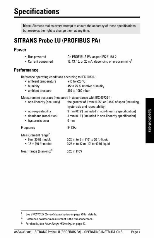
SITRANS Probe LU (PROFIBUS PA) Power
• Bus powered On PROFIBUS PA, as per IEC 61158-2• Current consumed 12, 13, 15, or 20 mA, depending on programming1
PerformanceReference operating conditions according to IEC 60770-1
• ambient temperature +15 to +25 °C• humidity 45 to 75 % relative humidity• ambient pressure 860 to 1060 mbar
Measurement accuracy (measured in accordance with IEC 60770-1)• non-linearity (accuracy) the greater of 6 mm (0.25") or 0.15% of span [including
hysteresis and repeatability]• non-repeatability 3 mm (0.12") [included in non-linearity specification]• deadband (resolution) 3 mm (0.12") [included in non-linearity specification]• hysteresis error 0 mm
Frequency 54 KHz
Measurement range2
• 6 m (20 ft) model: 0.25 m to 6 m (10" to 20 ft) liquid• 12 m (40 ft) model: 0.25 m to 12 m (10" to 40 ft) liquid
Near Range (blanking)3 0.25 m (10")
Note: Siemens makes every attempt to ensure the accuracy of these specifications but reserves the right to change them at any time.
1. See PROFIBUS Current Consumption on page 79 for details.2. Reference point for measurement is the transducer face.3. For details, see Near Range (Blanking) on page 37.

Page 8 SITRANS Probe LU (PROFIBUS PA) – OPERATING INSTRUCTIONS A5E32337708
mm
mm
m
Spec
ifica
tions
Update time1 • 12 mA loop current 6.0 s (typical), maximum 16.0 s• 13 mA loop current 5.0 s (typical), maximum 14.0 s• 15 mA loop current 3.7 s (typical), maximum 8.0 s• 20 mA loop current 2.4 s (typical), maximum 4.0 s
Beam angle 10° at –3 dB boundary
Temperature compensation built in to compensate over temperature range
Memory• non-volatile EEPROM • no battery required
InterfacePROFIBUS PA
• configuration Siemens SIMATIC PDM (PC), or Siemens infrared handheld programmer
• display (local) multi-segment alphanumeric liquid crystal with bar graph (representing level)
MechanicalProcess Connections
• threaded connection 2” NPT, BSP, or G (BS EN ISO 228-1) /PF• flange connections 3" (80 mm) universal flange• other connections FMS 200 mounting bracket, or customer-supplied
mount
Transducer (2 options)• ETFE (ethylene-tetrafluoroethylene), or • PVDF (polyvinylidene fluoride)
Enclosure • body construction PBT (polybutylene terephthalate)• lid construction PEI (polyether imide)• conduit entry 2 x M20x1.5 cable gland, or 2 x 1/2" NPT thread• ingress protection Type 4X/NEMA 4X, Type 6/NEMA 6, IP67, IP682 (see
note below regarding approved hubs)
Weight Standard model 2.1 kg (4.6 lb)
1. Temperature dependent: typical value at +20 °C (+68 °F); maximum value at +80 °C (+176 °F)2. Submergence test under water at 2 m (6.5 ft) depth for 24 hours.

A5E32337708 SITRANS Probe LU (PROFIBUS PA) – OPERATING INSTRUCTIONS Page 9
mm
mm
m
Specifications
Environmental• location indoor/outdoor• altitude 5000 m (16,404 ft) max.• ambient temperature 40 to +80 °C (40 to +176 °F)• relative humidity suitable for outdoor
(Type 4X/NEMA 4X, Type 6 /NEMA 6, IP67, IP68 enclosure)
• installation category I• pollution degree 4• pressure rating 0.5 bar g/7.25 psi g
Process• temperature
(at flange or threads) 40 to +85 °C (40 to +185 °F) • pressure (vessel) 0.5 bar g/7.25 psi g
Approvals (verify against device nameplate)• General CSAUS/C, FM, CE, C-TICK
• Hazardous Intrinsically Safe: (Europe) ATEX II 1 G Ex ia IIC T4 Ga
(US/Canada) FM/CSA1: barrier required Class I, Div. 1, Groups A, B, C, D Class II, Div. 1, Groups E, F, G Class III T4
(Brazil) INMETRO DNV 12.0084XEx ia IIC T4 GaIP67/IP68-40 ºC Ta +80 ºCDNV #OCP 0017
ABNT NBR IEC 60079-0:2008ABNT NBR IEC 60079-11:2009 eABNT NBR IEC 60079-26:2008
Non-incendive: (US) FM2 : Class I, Div. 2, Groups A,B, C, D T5
Notes: • Please check the ambient and operating temperatures above; Process below; and
Approvals (verify against device nameplate) below, for the specific configuration you are about to use or install.
• Approved dust-tight and water-tight conduit seals are required for outdoor Type 4X / NEMA 4X, Type 6 / NEMA 6, IP67, IP68 locations..
1. See FM/CSA Intrinsically Safe Connection Drawing on page 109 for drawing number 23650617.2. See FM: Class I, Div. 2 Connection Drawing on page 113 for drawing number 23650583.

Page 10 SITRANS Probe LU (PROFIBUS PA) – OPERATING INSTRUCTIONS A5E32337708
mm
mm
m
Spec
ifica
tions
Programmer (infrared keypad)Siemens Infrared IS (Intrinsically Safe) handheld programmer: for all locations, including hazardous.
• approval ATEX II 1GD, Ex ia IIC T4 Ga, Ex iaD 20 T135 °C, SIRA 01ATEX2147IECEx SIR 09.0073 Ex ia IIC T4 Ga, Ex iaD 20 T135 °C
FM/CSA: Class I, Div. 1, Groups A, B, C, D• ambient temperature 20 to +50 °C (5 to +122 °F)• interface proprietary infrared pulse signal• power 3V lithium battery (non-replaceable)• weight 150 g (0.3 lb)• color black

A5E32337708 SITRANS Probe LU (PROFIBUS PA) – OPERATING INSTRUCTIONS Page 11
mm
mm
m
Installation
Installation
Mounting LocationRecommendations:
• Ambient temperature within –40 to +80 °C (–40 to +176 °F).• Easy access for viewing the display and programming via the handheld programmer.• An environment suitable to the housing rating and materials of construction. • Keep the sound path perpendicular to the material surface. .
WARNINGS: • Installation shall only be performed by qualified personnel and in
accordance with local governing regulations.• SITRANS Probe LU is to be used only in the manner outlined in this
manual, otherwise protection provided by the equipment may be impaired.
Notes: • Please refer to the device nameplate for approval information.• Ideally, mount SITRANS Probe LU so that the face of the transducer is at least
300 mm (1 ft) above the highest anticipated level.
process temperature–40 to 85 °C (–40 to 185 °F)
ambient temperature surrounding enclosure–40 to +80 °C (–40 to +176 °F) flange adaptor (option)
customer-supplied flange

Page 12 SITRANS Probe LU (PROFIBUS PA) – OPERATING INSTRUCTIONS A5E32337708
mm
mm
m
Inst
alla
tion
Precautions:
• Avoid proximity to high voltage or current wiring, high voltage or current contacts, and to variable frequency motor speed controllers.
• Avoid interference to the sound path from obstructions or from the fill path
Mounting Instructions
SITRANS Probe LU is available in three thread types:• 2" NPT• 2" BSP• PF2/G (BS EN ISO 228-1)
1. Before inserting SITRANS Probe LU into its mounting connection, ensure that the threads are of the same type to avoid damaging them.
2. Simply screw SITRANS Probe LU into the process connection and hand tighten or using a strap wrench to seat gasket if required (1/4 turn past hand tight is recommended).
Note: • Ideally, mount SITRANS Probe LU so that the face of the transducer is at least 300
mm (1 ft) above the highest anticipated level.
seam
ladder rungs
pipe
Fill
The sound path should be:• perpendicular to the
monitored surface• clear of rough walls,
seams, rungs, or other obstructions
• clear of the fill path 10 °
A5E32337708 SITRANS Probe LU (PROFIBUS PA) – OPERATING INSTRUCTIONS Page 13
mm
mm
m
Installation
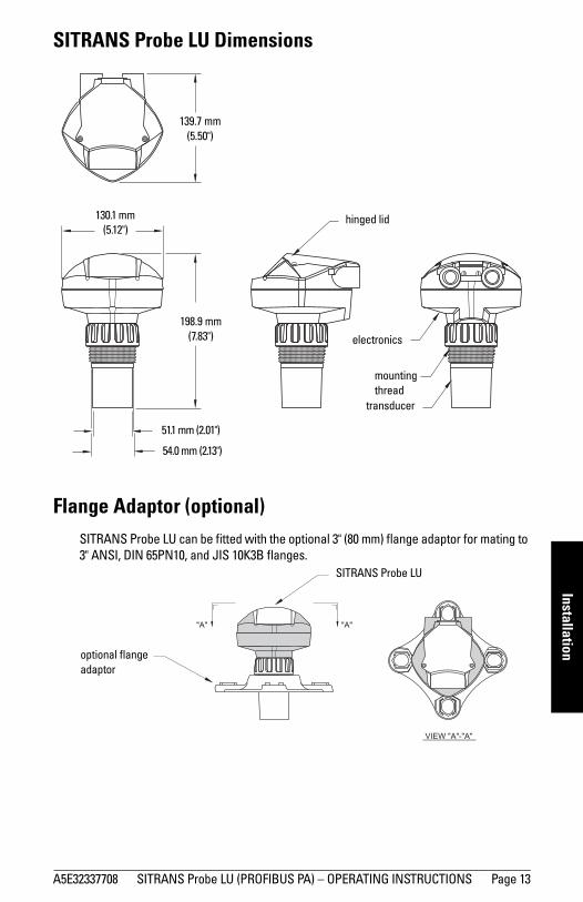
SITRANS Probe LU Dimensions.
Flange Adaptor (optional)SITRANS Probe LU can be fitted with the optional 3" (80 mm) flange adaptor for mating to 3" ANSI, DIN 65PN10, and JIS 10K3B flanges.
transducer
mounting thread
electronics
hinged lid
198.9 mm (7.83")
139.7 mm (5.50")
51.1 mm (2.01")
130.1 mm (5.12")
54.0 mm (2.13")
optional flange adaptor
"A" "A"
VIEW "A"-"A"
SITRANS Probe LU

Page 14 SITRANS Probe LU (PROFIBUS PA) – OPERATING INSTRUCTIONS A5E32337708
Wiri
ng
Wiring
Power1
Connecting the SITRANS Probe LU
1. Strip the cable jacket for approximately 70 mm (2.75") from the end of the PROFIBUS PA cable, and thread the wires through the gland2.
WARNINGS:DC terminals shall be supplied from an SELV1 source in accordance with IEC-1010-1 Annex H.
All field wiring must have insulation suitable for rated voltages.
1. Safety Extra Low Voltage
Notes: • For detailed information on Intrinsically Safe setups, see Appendix J: Hazardous
area installations on page 103.• Please see FM: Class I, Div. 2 Connection Drawing on page 113 for drawing number
23650583.• The non-metallic enclosure does not provide a continuous ground path between
conduit connections: use grounding-type bushings and jumpers.• Separate cables and conduits may be required to conform to standard
instrumentation wiring practices, or electrical codes.
2. If cable is routed through conduit, use only approved suitable-size hubs for waterproof applications.
cover screws
threaded connection
cable gland for 2 x 1/2" NPT metallic cable entry
terminals for PROFIBUS PA cable
cable

A5E32337708 SITRANS Probe LU (PROFIBUS PA) – OPERATING INSTRUCTIONS Page 15
Wiring
2. Connect the wires to the terminals as shown below (the Probe LU [PROFIBUS PA] is not polarity-sensitive).
3. Ground the instrument according to local regulations. • For Intrinsically Safe applications, connect the cable shield to the instrument
shield connection1, and ground the shield connection to an external ground that is connected to an equal-potential grounding grid. For more detail on Explosion Protection, you can download the brochure Siemens Process Automation Explosion Protection (part number A5E00265440) from: www.siemens.com/level, under Brochures/General.
• For general purpose applications, ground the shield at one point only (usually the power supply side) and continue the shield from device to device, connecting it to the shield connection in each Probe LU.
4. Tighten the gland to form a good seal.5. Close the cover and tighten screws: please do not overtighten screws.
Recommended torque is 0.5 to 1.1 N-m (5 to 10 in-lb).
1. The instrument shield connection is internally connected to the external ground lug.
Note: PROFIBUS PA must be terminated at both extreme ends of the cable for it to work properly. Please refer to the PROFIBUS PA User and Installation Guidelines (order number 2.092), available from www.profibus.com.
shield wire

Page 16 SITRANS Probe LU (PROFIBUS PA) – OPERATING INSTRUCTIONS A5E32337708
mm
mm
m
Star
tup
StartupOnly two steps are necessary for a Quick Setup (see page 19 for detailed instructions):
1. Use the handheld programmer to set the PROFIBUS address locally.2. Use SIMATIC PDM to calibrate the four set points: High and Low Calibration Point,
and High and Low Level Point.
SITRANS Probe LU automatically starts up in RUN mode and detects the material level. The LCD displays the material level referenced from the Low Level Point1 (the output of Analog Input Function Block 1/AIFB1). System status is displayed on the LCD, or on a remote communications terminal.2
3
Startup Display (RUN mode)
1. See Calibration on page 20 for an illustration.
Note: SITRANS Probe LU (PROFIBUS PA) continues to monitor in and out values even when the device is in PROGRAM mode.
2. See Loss of Echo (LOE) on page 36, for more details.3. For a list of fault codes, their meanings, and corrective actions, please see Acyclic
Extended Diagnostics (General Fault Codes) on page 30.
Normal operation
1
3 4
52
67
1 – Primary region displays material level (Output of the active AIFB)
2 – Menu number (displays the number of the active AIFB: 1 or 2)
3 – Echo status indicator: Reliable Echo or Unreliable Echo
(The Unreliable Echo border flashes if LOE is pending2. When LOE becomes active, the border is solid and the text region displays S: 0.)
4 – Bar graph border (always visible in RUN mode)
5 – Units or Percent
6 – Active bar graph represents material level
(Lowest bar flashes once per second indicating device is not frozen.)
7 – Secondary region can display one of the following:
• internal electronics temperature• value representing echo confidence• distance1 (Secondary Value 2)• general status information, or a fault code3
Failsafe operation
3
5
67
2

A5E32337708 SITRANS Probe LU (PROFIBUS PA) – OPERATING INSTRUCTIONS Page 17
mm
mm
m
Startup
Programming SITRANS Probe LU (PROFIBUS PA)The parameters that control the operation of the Probe LU are organized into function groups, and arranged in a 4-level menu structure that can be accessed either via the handheld programmer, or via PDM and PROFIBUS PA. (For charts showing the complete menu structure, please see Appendix E: LCD menu structure on page 49.)
The handheld programmer1
To activate PROGRAM mode, point the handheld programmer at the display from a
maximum distance of 600 mm (2 ft), and press the Mode key .
Within Program Mode, the handheld programmer has two sub-modes of operation: Navigation and Edit.
• Press Mode key to switch from RUN to PROGRAM and enter Navigation Mode: the rightmost digit of the menu number flashes, and the PROGRAM icon is not visible.
• Press Right arrow a second time to change the mode from Navigation to Edit mode.
• In Edit mode, the PROGRAM icon appears and flashes.
1. For more instructions on local programming using the handheld programmer, please see Appendix D: programming via the handheld programmer on page 42.
Note: For Quick Access to parameters via the handheld programmer, press Mode key to activate PROGRAM mode, then enter the menu number (see Appendix E: LCD
menu structure on page 49).
display
hand-held programmer
max. 600 mm (2 ft)
5
9
C
6
0
7 8
1 2 3 4
numeric keys
function keys

Page 18 SITRANS Probe LU (PROFIBUS PA) – OPERATING INSTRUCTIONS A5E32337708
mm
mm
m
Star
tup
PROGRAM Mode Display
When you activate PROGRAM mode for the first time in any power cycle, the LCD displays the first menu. If, during the same power cycle, you switch to RUN mode, and then back to PROGRAM mode, then the LCD will display the menu or item that was last accessed in PROGRAM mode.
Security
Local operation enable
Local Operation can be enabled or disabled via PDM (see details under Setting the PROFIBUS address via the handheld programmer on page 19).
Write locking
Write locking prevents any changes to parameters, either via PDM or the handheld programmer, but still allows access to the device (see page 76).
Remote operation enable
Remote Operation can be enabled or disabled via the handheld programmer (see page 45).
Master Reset
Open the menu Device – Master Reset to access the reset options. (See page 46 for handheld programmer instructions.)
Note: SITRANS Probe LU (PROFIBUS PA) continues to monitor In and Out values even when the device is in PROGRAM mode.
1 – Primary region (displays parameter value)2 – Menu number region (displays Menu number)3 – PROGRAM mode icon4 – Secondary region (displays text label)
1
2 3
4

A5E32337708 SITRANS Probe LU (PROFIBUS PA) – OPERATING INSTRUCTIONS Page 19
mm
mm
m
Startup
Quick Setup
Activating SITRANS Probe LU
Power up the instrument. SITRANS Probe LU starts in RUN mode, and the LCD displays the output of AIFB1.
Setting the PROFIBUS address via the handheld programmer 1
1. Press Mode to activate PROGRAM
mode and open Menu level 1.
2. Press Right ARROW twice to navigate
to PROFIBUS address.
3. Press Right ARROW again to open Edit
mode: the PROGRAM icon will flash.
4. Key in a new value and press Right ARROW
to accept it.
The LCD displays the new value; PROGRAM
icon disappears, and the last menu digit
flashes to indicate Navigation mode.
5. Press Mode to return to RUN mode.
Note: Keep infrared devices such as laptops, cell phones, and PDAs, away from SITRANS Probe LU to prevent inadvertent operation.
Notes: • Local programming must be enabled, to allow changes. (In PDM, go to Identification
> Device > Local Operation Enable and select the desired setting.)
• CLEAR can be used to clear the field.
• Press Right ARROW to open Edit mode: the PROGRAM icon flashes.
• Press Left ARROW to cancel Edit mode: the Menu number flashes (the
PROGRAM icon is not visible).
1. Default address is 126.
C
Menu level: last digit flashes in Navigation mode.
Program icon: flashes in Edit mode.
Right-most digit flashes in Navigation mode.

Page 20 SITRANS Probe LU (PROFIBUS PA) – OPERATING INSTRUCTIONS A5E32337708
mm
mm
m
Star
tup
Performing calibration via PROFIBUS PATo use PROFIBUS PA, you will need a PC configuration tool: we recommend SIMATIC PDM. Please consult the operating instructions or online help for details on using SIMATIC PDM. (An Application Guide SMPI PROFIBUS PA instruments and SIMATIC PDM can be downloaded from the Probe LU product page of our website, at: https://pia.khe.siemens.com/index.asp?Nr=11157)
Changing parameter settings
• First launch SIMATIC PDM, connect to SITRANS Probe LU, and upload data from the device.
• Adjust parameter values in the parameter view field (right side of screen).• After adjusting the value, press Enter (the status fields read Changed).• When you have completed the adjustments, open the Device menu, download data
to the device, and save parameter settings offline (the status fields go blank).
Calibration
Only four settings are required for a Quick Setup:• High Calibration Point and High Level Point• Low Calibration Point and Low Level Point1
23
4
1. Default 0. For more details, see page 82.2. The value produced by the echo processing, representing the distance from the
Sensor Reference Point to the target. 3. Level Value: the level measured in level units.4. Distance is referenced from the tank reference level to the target (see page 58 for
details on SV2 and SV3).
High LevelPoint
(default: 100%)
Sensor Reference Point (transducer face)
Sensor Value2
Low LevelPoint
(default: 0%)
Level3
Level Offset1Secondary Value 1
Low Calibration Point
Tank reference pointHigh
Calibration Point
FarRange
Near Range
Distance4
(SV2 or SV3)
Sensor Offset1

A5E32337708 SITRANS Probe LU (PROFIBUS PA) – OPERATING INSTRUCTIONS Page 21
mm
mm
m
Startup
Calibration – steps 1 to 7
1. Open the menu Device – Sensor Calibration and select the button Dry Calibration. (Click on Additional Information to see the schematic showing the PROFIBUS parameters.)
2. Enter the new value for Low Calibration Point (default units are meters).3. Enter the corresponding value for Low Level Point in percent (default is 0).4. Enter the new value for High Calibration Point (default units are meters).5. Enter the corresponding value for High Level Point in percent (default is 100).6. Click on Transfer.7. SITRANS Probe LU is now ready to operate.
Using Auto False Echo SuppressionIf SITRANS Probe LU displays a false high level, or the reading is fluctuating between the correct level and a false high level, you can use the Auto False Echo Suppression parameters to prevent false echo detection. See TVT setup on page 93 for instructions.
Level application exampleThe Primary Value (PV) can be level or volume1. If volume conversion is not selected, the PV will be the same as the Secondary Value 1 (SV1). SV1 is the sum of level plus level offset (if any).
1. For details, see How the LTB works: on page 57.
Sensor Value
Low LevelPoint = 0%
Level
Sensor Offset
High Calibration Point = 3 m
High Level Point = 100%
Near Range
Far Range
Level Units: Sensor Units:
Low Calibration Point = 5 m
Level Offset (if any)
Secondary Value 1

mm
mm
m
Rem
ote
Ope
ratio
n : P
A
Page 22 SITRANS Probe LU (PROFIBUS PA) – OPERATING INSTRUCTIONS A5E32337708
Remote operation via PROFIBUS PA
SITRANS Probe LU (PROFIBUS PA) is a Class B, Profile Version 3.0, rev. 1, PA device. It supports Class 1 Master for cyclic and acyclic data exchange, and Class 2 for acyclic services. The full range of SITRANS Probe LU functions is available only over a PROFIBUS PA network.
PROFIBUS PA is an open industrial protocol. Full details about PROFIBUS PA can be obtained from PROFIBUS International at www.profibus.com.
To use PROFIBUS PA, you will need a PC configuration tool: we recommend SIMATIC PDM. Please consult the operating instructions or online help for details on using SIMATIC PDM. (You can find more information at www.fielddevices.com: go to Products and Solutions > Products and Systems > Process Device Manager.)
SIMATIC PDMSIMATIC PDM is a software package used to design, parameterize, commission, diagnose and maintain SITRANS Probe LU and other process devices.
SIMATIC PDM contains a simple process monitor of the process values, alarms, and status signals of the device. SIMATIC PDM allows you to manage process device data in the following ways:
• display• set• change• compare• check the plausibility• manage• simulate
Device DescriptionIn order to use Process Device Manager (PDM) with PROFIBUS PA, you will need the Device Description for SITRANS Probe LU, which will be included with new versions of PDM. When you set up a new device, you can locate the Device Description in Device Catalog, under Sensors/Level/Echo/Siemens. If you do not see SITRANS Probe LU under Siemens, you can download it from the product page of our web site at: https://pia.khe.siemens.com/index.asp?Nr=11157 under Downloads.

mm
mm
m
Remote O
peration : PA
A5E32337708 SITRANS Probe LU (PROFIBUS PA) – OPERATING INSTRUCTIONS Page 23
ConfigurationTo configure a PROFIBUS PA Class 1 Master (for example, a PLC), you will need a GSD file.
The GSD fileThe GSD file (SIEM8124.gsd for the 6 m Probe LU; or SIEM8123.gsd for the 12 m Probe LU) is available from the product page of our web site at: https://pia.khe.siemens.com/index.asp?Nr=11157 under Downloads.
Setting the PROFIBUS addressWhen your instrument is shipped, the PROFIBUS address is set to 126. You can set it locally (see Setting the PROFIBUS address via the handheld programmer on page 19) or remotely via the bus, using a parameterization tool such as SIMATIC PDM (see Device Address (default 126) on page 73).
Bus Termination
Power DemandsTo determine how many devices can be connected to a bus line, calculate the combined maximum current consumption of all the connected devices and allow a current reserve for safety.
In the case of the Probe LU (PROFIBUS PA), the maximum PROFIBUS current is user-selectable, and can be either 12, 13, 15, or 20 mA. (See PROFIBUS Current Consumption on page 79.)
ValuesRange: 0 to 126
Pre-set: 126
Note: In order for PROFIBUS PA to work properly, it must be terminated at both extreme ends of the cable. Please refer to the PROFIBUS PA User and Installation Guidelines (order number 2.092), available from www.profibus.com.

mm
mm
m
Rem
ote
Ope
ratio
n : P
A
Page 24 SITRANS Probe LU (PROFIBUS PA) – OPERATING INSTRUCTIONS A5E32337708
Cyclic versus Acyclic DataWhen you request data from a device via PROFIBUS PA, there are two possible data transfer methods. Cyclic data is provided at every bus scan: acyclic data is requested and provided as needed.
Input information is always requested at every bus scan and is set up as cyclic data. Configuration information is only needed periodically and is set up as acyclic data.
Cyclic DataWhen you configure SITRANS Probe LU on the PROFIBUS PA bus, there are two slots available for modules.
Slot 0 always transmits AIFB1 information1. Slot 1 defaults to Free Place, but can be changed to AIFB2 information. If you do not wish to have data transmitted, then you must use a Free Place module in that slot.
Each of the two Analog Input Function Blocks can be set up to return Level, Distance, or Volume. Within the function blocks, the values are scaled according to the user requirements (please see Analog Input Function Blocks 1 and 2 on page 58 for details).
AIFB1 and AIFB2 return 5 bytes of data each:
The first 4 bytes are the floating point representation (IEEE) of the variable. The variables are the outputs of the function block. The 5th byte is the status word, and the list of possible values is given in the chart below.
The 5 bytes must be read consistently, in a contiguous chunk: they cannot be read byte by byte, and cannot suffer an interrupt. If you are using an S7-300 / 400, you will need to use SFC14 DPRD_DAT: Read Consistent Data of a Standard PD Slave.
Note: Each of the slots has to have a module defined in it.
1. For more information, please see Analog Input Function Blocks 1 and 2 on page 58.
Floating Point Status
AIFB2
AIFB1 byte 1 byte 2 byte 3 byte 4 byte 5
byte 6 byte 7 byte 8 byte 9 byte10byte10

mm
mm
m
Remote O
peration : PA
A5E32337708 SITRANS Probe LU (PROFIBUS PA) – OPERATING INSTRUCTIONS Page 25
Status ByteThese codes are available when Condensed Status is not enabled (default state).
Status Codes for Good Quality
Values in hex notation Description
0x80 Data is GOOD.
0x84 A parameter in the function block has been changed: status active for 10 s.
0x89 Active low warning.
0x8A Active high warning.
0x8D Active low alarm.
0x8E Active high alarm.
Status Codes for Uncertain Quality
Values in hex notation Description
0x4B Value is a substituted value (normally used in Fail-safe).
0x4C/0x4F Initial value.
0x47 Last usable value.
Status Codes for Bad Quality
Values in hex notation Description
0x10 The LOE timer has expired: this could be caused by LOE or by a sensor malfunction: value is BAD.
0x01 There is an error in the configuration of the function blocks in PROFIBUS PAa.
a. This could happen when a firmware download has been done, but a system reset has not been done. This could also happen if the function blocks are not configured properly using the handheld programmer, PDM or acyclic services.
0X1F The function block, or level transducer block, has been placed out of service.

mm
mm
m
Rem
ote
Ope
ratio
n : P
A
Page 26 SITRANS Probe LU (PROFIBUS PA) – OPERATING INSTRUCTIONS A5E32337708
Condensed StatusThese codes are available when Condensed Status is enabled.
Hex value Status – GOOD Description
0x80 GOOD – ok No error or special condition is associated with this value.
0x84 GOOD – update event Set if the value is good and the block has an active Update event. (This status remains active for 20 sec-onds.)
0x86 GOOD – active advi-sory alarm
Set if the value is good and the block has an active Alarm.
0x80 ...0x8E
GOOD – limit check/update event SeeStatus Codes for Good Quality on page 25 .
0xA0 ...0xA3
GOOD – initiate fail safe
This fault is not generated by the product, but can be simulated.
0xA4 ...0xA7
GOOD – maintenance required
Value is valid. Maintenance is recommended within a medium-term period.
0xA8 ...0xAB
GOOD – maintenance demanded
Value is valid. Maintenance is demanded within a short-term period.
0xBC ...0xBF
GOOD – function check
Device performs internal function check without influ-encing the process. Value is valid.
Hex value
Status – UNCERTAIN Description
0x45 UNCERTAIN – substi-tute set
Output of Failsafe logic only.
0x4F UNCERTAIN – initial value
Default value as long as no measured value is available or until a diagnosis is made that affects the value and the status accorded to it.
0x68 ...0x6B
UNCERTAIN – main-tenance demanded
Usability of the process value depends on the applica-tion. Value is potentially invalid. Cause is a weara detected in the device. Maintenance is demanded within a short-term period.

mm
mm
m
Remote O
peration : PA
A5E32337708 SITRANS Probe LU (PROFIBUS PA) – OPERATING INSTRUCTIONS Page 27
0x73 UNCERTAIN – simu-lated value, start
Indicates the start of a simulation. Simulation of a measured value or Input FB mode changes from AUTO to MAN. • This status remains active for at least 10 seconds:
– after enabling simulation– after setting the FB to MAN mode– after a restart (e.g. power down cycle) if the simu-
lation is enabled or the FB is in MAN mode– after passivation is cleared if simulation is
enabled or the FB is in MAN mode• In MAN mode the status remains until a subsequent
write command overwrites the OUT value after the 10 seconds have expired.
• In simulation mode the written status is buffered and appears in the value flow after 10 seconds. However the new written SIMULATE parameter with its status can be read before the 10 seconds have expired.
0x74 ...0x77
UNCERTAIN – simu-lated value, end
Indicates the end of a simulation.Simulation of a measured value is disabled or Input FB mode changes from MAN to AUTO. This Status remains active for 10 seconds after simula-tion ends. While this status is active there is no reliable process value. Measured values and their status are updated afterwards.
a. See Wear on page 117 for more detail.
Hex value Status BAD Description
0x00 BAD – non specific Proxy determines that a device does not communicate.
0x23 BAD – passivated (diagnostics alerts disabled)
Configured failsafe value is used, accompanied by this status.
0x24 ...0x27
BAD – maintenance alarm, more diagnosis available
No measurement available because of a failure.
0x25 BAD – process related, no mainte-nance
No measurement available because of invalid process conditions.
0x3C ...0x3F
BAD – function check / local over-ride, value not usable
Occurs during cleaning or calibration process.
Hex value
Status – UNCERTAIN Description (cont’d)

mm
mm
m
Rem
ote
Ope
ratio
n : P
A
Page 28 SITRANS Probe LU (PROFIBUS PA) – OPERATING INSTRUCTIONS A5E32337708
DiagnosticsAll diagnostic information shown below is viewable via PDM.
Diagnosis reply (applies only to cyclic masters)This is a response to a GET-DIAG message.
During DPV0 data exchange, the PROFIBUS PA slave will notify the Master when a serious error occurs. The Master will then send a Diagnosis request. The reply to this request is normally logged in the PLC and is referred to as the Hex values.
The reply may contain two parts. The first part is 6 bytes long and is defined by the PROFIBUS standard. If there is a second part, it is called the extended diagnostic and it is eight bytes long. The last four bytes of the extended diagnostic message give the error code shown below. (The same information is also available acyclically via the Diagnosis Object.)
Acyclic DiagnosticsThis consists of four bytes.
Hex values Byte Bit DescriptionIndication classa
0x01000000
0
0 Electronics failure R
0x02000000 1 Mechanical failure R
0x04000000 2 Motor Temperature too high R
0x08000000 3 Electronics temperature too high R
0x10000000 4 Memory error R
0X20000000 5 Measurement failure R
0X40000000 6 Device not initialized (no calibration) R
0x80000000 7 Self calibration failed R

mm
mm
m
Remote O
peration : PA
A5E32337708 SITRANS Probe LU (PROFIBUS PA) – OPERATING INSTRUCTIONS Page 29
Values of the DIAGNOSIS bit:0 = not set1 = set
0x00010000
1
0 Zero point error (limit position) R
0x00020000 1 Power supply failure (electrical, pneu-matic) R
0x00040000 2 Configuration invalid R
0x00080000 3 New startup carried out (Warm Start) A
0x00100000 4 Restart carried out (Cold Start) A
0X00200000 5 Maintenance required R
0X00400000 6 Characterization invalid R
0X00800000 7
Set to 1 (one), if the Ident_Number of the running cyclic data transfer and the value of Physical Block IDENT__NUMBER_SELECTOR parame-ter are different.
R
2 0 to 7 Reserved for use within the PNOb
3 0 to 6 Reserved for use within the PNO
0X00000080 7 More diagnosis information is available
a. R indicates the message remains active as long as the reason for the message exists.A indicates the message will automatically reset after 10 seconds.
b. PNO – PROFIBUS User Organization
Hex values Byte Bit DescriptionIndication classa
(cont’d)

mm
mm
m
Rem
ote
Ope
ratio
n : P
A
Page 30 SITRANS Probe LU (PROFIBUS PA) – OPERATING INSTRUCTIONS A5E32337708
Acyclic Extended Diagnostics (General Fault Codes)In addition to the extended diagnostics available by cyclic data exchange (shown above), further extended diagnostics are available via acyclic communications. This consists of six bytes. Please see Appendix G: Asynchronous Communications Data Map on page 61 for the location of the Extended Diagnostics.
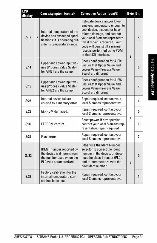
Note: Certain fault codes (identified by an asterisk [*] in the table below) will persist until a manual reset has been performed (see Reset Fault on page 74).
LCD display
Cause/symptom Corrective Action Byte Bit
S:0
Device unable to get a mea-surement within the Fail-safe timer period. Possible causes: faulty installation, material buildup, foaming/other adverse process con-ditions, invalid calibration range.
Ensure installation details are correct; ensure no material buildup; adjust process condi-tions to minimize foam or other adverse conditions; correct range calibration. If fault persist, contact your local Siemens rep-resentative. 0
0
S:1 Broken internal HF cable.Reset power. If fault persists, contact your local Siemens rep-resentative: repair required.
1
S:2 No power supply to technology board.
Reset power. If fault persists, contact your local Siemens rep-resentative: repair required.
2
S:10Input parameters High Cali-bration Point and Low Cali-bration Point are the same.
Check calibration settings of device. Ensure settings for High Calibration Point and Low Cali-bration Point are different. 1
3
S:11 Internal temperature sen-sor has failed.
Repair required: contact your local Siemens representative. 4
mm
mm
m
Remote O
peration : PA
A5E32337708 SITRANS Probe LU (PROFIBUS PA) – OPERATING INSTRUCTIONS Page 31
S:12 *
Internal temperature of the device has exceeded speci-fications: it is operating out-side its temperature range.
Relocate device and/or lower ambient temperature enough to cool device. Inspect for heat-related damage, and contact your local Siemens representa-tive if repair is required. Fault code will persist till a manual reset is performed using PDM or the LCD interface.
1
5
S:14Upper and Lower input val-ues (Process Value Scale) for AIFB1 are the same.
Check configuration for AIFB1. Ensure that Upper Value and Lower Value (Process Value Scale) are different.
6
S:15Upper and Lower input val-ues (Process Value Scale) for AIFB2 are the same.
Check configuration for AIFB2. Ensure that Upper Value and Lower Value (Process Value Scale) are different.
7
S:28 Internal device failure caused by a memory error.
Repair required: contact your local Siemens representative.
3
4
S:29 EEPROM damaged. Repair required: contact your local Siemens representative. 5
S:30 EEPROM corrupt.Reset power. If error persist, contact your local Siemens rep-resentative: repair required.
6
S:31 Flash error. Repair required: contact your local Siemens representative. 7
S: 32
IDENT number reported by the device is different from the number used when the PLC was parameterized.
Either use the Ident Number selector to correct the Ident number in the device; or discon-nect the class 1 master (PLC), and re-parameterize with the new Ident number.
4
0
S:33Factory calibration for the internal temperature sen-sor has been lost.
Repair required: contact your local Siemens representative. 1
LCD display
Cause/symptom (cont’d) Corrective Action (cont’d) Byte Bit
mm
mm
m
Rem
ote
Ope
ratio
n : P
A
Page 32 SITRANS Probe LU (PROFIBUS PA) – OPERATING INSTRUCTIONS A5E32337708
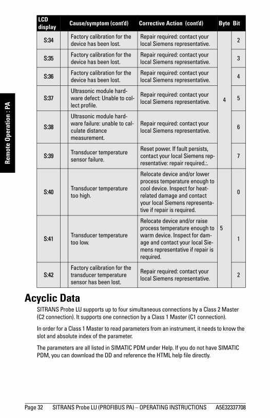
Acyclic DataSITRANS Probe LU supports up to four simultaneous connections by a Class 2 Master (C2 connection). It supports one connection by a Class 1 Master (C1 connection).
In order for a Class 1 Master to read parameters from an instrument, it needs to know the slot and absolute index of the parameter.
The parameters are all listed in SIMATIC PDM under Help. If you do not have SIMATIC PDM, you can download the DD and reference the HTML help file directly.
S:34 Factory calibration for the device has been lost.
Repair required: contact your local Siemens representative.
4
2
S:35 Factory calibration for the device has been lost.
Repair required: contact your local Siemens representative. 3
S:36 Factory calibration for the device has been lost.
Repair required: contact your local Siemens representative. 4
S:37Ultrasonic module hard-ware defect: Unable to col-lect profile.
Repair required: contact your local Siemens representative. 5
S:38
Ultrasonic module hard-ware failure: unable to cal-culate distance measurement.
Repair required: contact your local Siemens representative. 6
S:39 Transducer temperature sensor failure.
Reset power. If fault persists, contact your local Siemens rep-resentative: repair required.:.
7
S:40 Transducer temperature too high.
Relocate device and/or lower process temperature enough to cool device. Inspect for heat-related damage and contact your local Siemens representa-tive if repair is required.
5
0
S:41 Transducer temperature too low.
Relocate device and/or raise process temperature enough to warm device. Inspect for dam-age and contact your local Sie-mens representative if repair is required.
1
S:42Factory calibration for the transducer temperature sensor has been lost.
Repair required: contact your local Siemens representative. 2
LCD display
Cause/symptom (cont’d) Corrective Action (cont’d) Byte Bit

mm
mm
m
Remote O
peration : PA
A5E32337708 SITRANS Probe LU (PROFIBUS PA) – OPERATING INSTRUCTIONS Page 33
To find the slot and index numbers via SIMATIC PDM, go to Help > Communications, and select the appropriate block from the list. For each parameter, the slot and the relative index is listed. For example:
Each block has a slot number and an Index Offset value.
To get the the absolute index for any parameter , add the Index Offset for the appropriate block to the relative index for that parameter. The parameter takes the slot number of the block in which it is located.
For example:
• Parameter Static Revision Number has relative index = 1 and is located on AIFB1.• It has Absolute Index = 17 (relative index 1 + index offset 16).• It is located at Slot 1 (the slot number for AIFB 1).
Configuration Example
To configure and use PROFIBUS PA with an S7-300/ 400 PLC
1. If SITRANS Probe LU is not listed in the STEP 7 device catalog, you can download the GSD file from the product page of our web site at: https://pia.khe.siemens.com/index.asp?Nr=11157 under Downloads.
2. Add the SITRANS Probe LU "rack": click and drag the SITRANS Probe LU folder from the hardware catalog.
3. Fill the "rack" with desired modules by dragging and dropping them from the hardware catalog.
4. After configuring PROFIBUS PA in steps 2 and 3, download it to the PLC.
5. Add code to the PLC program to read data consistently using the SFC14.
Accessing parameters remotely
FunctionsThe PDM Device Menu gives you access to the following functions:
• Upload from/Download to Device• Set Address• Simulation• Master Reset
AIFB 1Index Parameter Datatype1 Static Revision No. UNSIGNED_INTEGER (2)
Block Name Slot Index OffsetPhysical block 0 16Transducer block 0 77AIFB 1 1 16AIFB 2 2 16

mm
mm
m
Rem
ote
Ope
ratio
n : P
A
Page 34 SITRANS Probe LU (PROFIBUS PA) – OPERATING INSTRUCTIONS A5E32337708
• Auto False Echo Suppression• Write Locking• Offset and Velocity Calibration• Sensor Calibration
Changing parameter settings
• First launch SIMATIC PDM, connect to SITRANS Probe LU1, and upload data from the device (the status fields change to Loaded).
• Adjust parameter values in the parameter view field (right side of screen).• After adjusting the value, press Enter (the status fields read Changed).• When you have completed the adjustments, open the Device menu, download data
to the device, and save parameter settings offline (the status fields go blank).
For a complete list of parameters, please see Appendix H: Parameter Descriptions on page 73.
1. PDM must have the correct device address of your instrument in order to connect.
A5E32337708 SITRANS Probe LU (PROFIBUS PA) – OPERATING INSTRUCTIONS Page 35
mm
mm
m
A: Technical Reference
Appendix A: Technical References
Principles of operationThe transducer emits a series of ultrasonic pulses: each pulse is reflected as an echo from the material and sensed by the transducer. The echo is processed by SITRANS Probe LU, using Siemens proven Sonic Intelligence techniques. Filtering is applied to help discriminate between the true echo from the material and false echoes from acoustic and electrical noise, and agitator blades in motion.
The time for the pulse to travel to the material and back is temperature-compensated, and then converted into distance for display, and a cyclic value for PROFIBUS PA output.
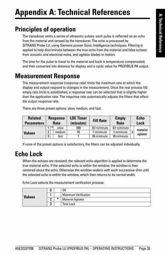
Measurement ResponseThe measurement response (response rate) limits the maximum rate at which the display and output respond to changes in the measurement. Once the real process fill/empty rate (m/s) is established, a response rate can be selected that is slightly higher than the application rate. The response rate automatically adjusts the filters that affect the output response rate.
There are three preset options: slow, medium, and fast.
If none of the preset options is satisfactory, the filters can be adjusted individually.
Echo LockWhen the echoes are received, the relevant echo algorithm is applied to determine the true material echo. If the selected echo is within the window, the window is then centered about the echo. Otherwise the window widens with each successive shot until the selected echo is within the window, which then returns to its normal width.
Echo Lock selects the measurement verification process:
Related Parameters
ResponseRate
LOE Timer (minutes) Fill Rate Empty
RateEcho Lock
Values1 * slow 100 0.1 m/minute 0.1 m/minute
2material agitator
2 medium 10 1 m/minute 1 m/minute3 fast 1 10 m/minute 10 m/minute
Values
0 Off1 Maximum Verification2 * Material Agitator3 Total Lock

Page 36 SITRANS Probe LU (PROFIBUS PA) – OPERATING INSTRUCTIONS A5E32337708
mm
mm
m
A: T
echn
ical
Ref
eren
ce• When Echo Lock is Off, SITRANS Probe LU responds immediately to a new
measurement (within the restrictions set by the Maximum Fill / Empty Rate). However, measurement reliability is affected.
• When Maximum Verification or Material Agitator is selected, a new measurement outside the Echo Lock Window must meet the sampling criteria.
• When Total Lock is selected, Echo Lock Window is pre-set to 0, and the window is automatically calculated after each measurement.
Loss of Echo (LOE)A loss of echo (LOE) occurs when the calculated measurement is judged to be unreliable because the echo confidence value has dropped below the echo confidence threshold. The LOE timer starts running, and if the LOE condition persists beyond the time limit set by the LOE timer, the Reliable Echo indicator is replaced by the Unreliable Echo indicator.
Reliable Echo indicator
Unreliable Echo indicator: border flashes when LOE is pending.
When LOE is active, border is solid and text region displays S: 0
Upon receiving a reliable echo, the loss of echo condition is aborted, the Reliable Echo indicator replaces the Unreliable Echo indicator, and the reading returns to the current level.
LOE TimerThe LOE timer determines the time (in minutes) to elapse after the last valid reading before Failsafe mode is activated. When the LOE timer expires, the material level to be reported is determined by Failsafe Mode.
Failsafe ModeFailsafe mode defines the reaction of the device if a Failsafe condition is detected. It may be triggered by a loss of echo, a bad configuration, or certain device faults. If Failsafe mode is activated by a fault, the instrument will go into Failsafe mode without delay (see Acyclic Extended Diagnostics (General Fault Codes) on page 30).
You can select can select one of three possible values to be reported when a Failsafe condition occurs:
• Default value (Failsafe value) used as output value.• Storing last valid output value.• Calculated output value is incorrect.

A5E32337708 SITRANS Probe LU (PROFIBUS PA) – OPERATING INSTRUCTIONS Page 37
mm
mm
m
A: Technical Reference
Failsafe valueFailsafe value is a user-defined value. This allows you to enter the safest output value for your application.
For example, you may want to select a user-defined high value to prevent an overfill (Failsafe Hi). Or you may want to select a low value to protect a pump from operating dry (Failsafe Lo).
Near Range (Blanking)The crystal which produces the transmit pulse has to stop vibrating before it can receive an echo. Near Range is the space in front of the transducer face where level measurement is not possible, because within that distance, the echo would return before the vibration had ceased.
The Near Range parameter allows you to set the distance in front of the transducer, within which any echoes will be ignored1.
False EchoesFalse echoes can appear during the receive cycle. They are often created by obstructions within the beam path, such as a ladder rung, and are usually indicated by an incorrect high level reading. Auto False-Echo Suppression is recommended.
Auto False-Echo SuppressionThe TVT adjustment parameters allow you to set a TVT (Time Varying Threshold) curve, so that SITRANS Probe LU will ignore false echoes.
The default TVT curve hovers above the echo profile, and effectively screens out small false echoes. But if an obstruction is causing a large echo before the material level echo, that echo will rise above the default TVT curve. You can use Auto False-Echo Suppression to filter it out. If possible, rotate the instrument before using Auto False-Echo Suppression, to lower the amplitude of false echoes.
1. The reference point for measuring Near Range is the transducer face. The minimum recom-mended Near Range value is 0.25 m (10"), but this can be increased.

Page 38 SITRANS Probe LU (PROFIBUS PA) – OPERATING INSTRUCTIONS A5E32337708
mm
mm
m
A: T
echn
ical
Ref
eren
ceWhen you set Auto False-Echo Suppression to Learn, the instrument learns the echo profile at that moment1. Then it uses the learned profile instead of the default TVT curve, for the distance set in Auto False Echo Suppression Distance. The learned profile (learned TVT curve) follows the echo profile, so that no large false echoes rise above the learned TVT curve. From the end of the Auto False-Echo Suppression Distance, the default TVT curve is used. The material level echo rises above this, and is selected as the true echo.
1. Turn on Auto False-Echo Suppression when the material level is substantially lower than process full level (ideally when the tank is empty or almost empty).
Display before Auto False Echo Suppression
default TVT curve TVT
Hover Level
false echo
true echo
Distance (meters)
Leve
l (db
)
Display after Auto False Echo Suppression
TVT curve(learned)
materiallevel
falseecho
Distance (meters)
Leve
l (db
)
A5E32337708 SITRANS Probe LU (PROFIBUS PA) – OPERATING INSTRUCTIONS Page 39
mm
mm
m
A: Technical Reference
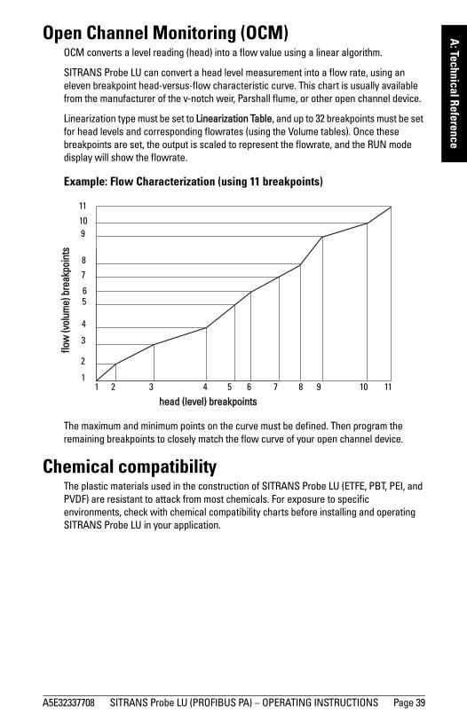
Open Channel Monitoring (OCM)OCM converts a level reading (head) into a flow value using a linear algorithm.
SITRANS Probe LU can convert a head level measurement into a flow rate, using an eleven breakpoint head-versus-flow characteristic curve. This chart is usually available from the manufacturer of the v-notch weir, Parshall flume, or other open channel device.
Linearization type must be set to Linearization Table, and up to 32 breakpoints must be set for head levels and corresponding flowrates (using the Volume tables). Once these breakpoints are set, the output is scaled to represent the flowrate, and the RUN mode display will show the flowrate.
Example: Flow Characterization (using 11 breakpoints)
The maximum and minimum points on the curve must be defined. Then program the remaining breakpoints to closely match the flow curve of your open channel device.
Chemical compatibilityThe plastic materials used in the construction of SITRANS Probe LU (ETFE, PBT, PEI, and PVDF) are resistant to attack from most chemicals. For exposure to specific environments, check with chemical compatibility charts before installing and operating SITRANS Probe LU in your application.
11
10
9
8
7
65
4
3
2
11 2 3 4 65 7 8 9
10
11
head (level) breakpoints
flow
(vol
ume)
bre
akpo
ints

Page 40 SITRANS Probe LU (PROFIBUS PA)– OPERATING INSTRUCTIONS A5E32337708
mm
mm
m
B: T
roub
lesh
ootin
g
Appendix B: Troubleshooting
1. Check the following:
• There is power at the instrument.• The LCD shows the relevant data.• Check whether any fault codes are being displayed (see Acyclic Extended
Diagnostics (General Fault Codes) on page 30 for a detailed list).• The device can be programmed using the handheld programmer.
2. Verify that the wiring connections are correct.
3. Check the PROFIBUS address and make sure all devices are at unique PROFIBUS addresses.
4. If you are unable to program the device via the handheld programmer, make sure local operation is enabled (see Local operation enable on page 44). Also make sure that Write Locking is Off (see Write locking on page 45).
5. If you try to set a SITRANS Probe LU parameter via remote communications, but the parameter remains unchanged, make sure remote operation is enabled (see Remote operation enable on page 45). Also make sure that Write Locking is Off (see Write Locking on page 76).
6. If you continue to experience problems, go to our website at www.siemens.com/processautomation, and check the FAQs for SITRANS Probe LU, or contact your Siemens representative.
7. If the PLC value equals the display value, but does not correspond to actual material level, either:• scaling in AIFB1 is incorrect, or• High Calibration Point is incorrectly entered, or• the wrong echo is being selected.
8. If the PLC value is not equal to the displayed value (regardless of actual material level), either: • you may not be looking at the right spot in the PLC, or• you may have programmed scaling into the PLC, instead of leaving all scaling to
be performed in the Probe LU, or• the PCL may not be communicating with the Probe LU. Check the network to
verify that you are communicating.
General Fault CodesFor a table listing the fault codes, meanings, and suggested corrective action to take, please see Acyclic Extended Diagnostics (General Fault Codes) on page 30.

A5E32337708 SITRANS Probe LU (PROFIBUS PA) – OPERATING INSTRUCTIONS Page 41
C: Maintenance
Appendix C: Maintenance
SITRANS Probe LU requires no maintenance or cleaning.
Unit Repair and Excluded LiabilityAll changes and repairs must be done by qualified personnel, and applicable safety regulations must be followed. Please note the following:
• The user is responsible for all changes and repairs made to the device.• All new components must be provided by Siemens Process Instruments Inc.• Restrict repair to faulty components only.• Do not re-use faulty components.

Page 42 SITRANS Probe LU (PROFIBUS PA) – OPERATING INSTRUCTIONS A5E32337708
mm
mm
m
D: L
ocal
Ope
ratio
n
Appendix D: programming via the handheld programmer
Although the complete range of parameters is only accessible via PDM1, you can access and adjust many of the parameters via the Siemens infrared handheld programmer.
• For the complete list of parameters, see Appendix H: Parameter Descriptions on page 73.
• Appendix E: LCD menu structure on page 49 gives a list of all parameters accessible via the handheld programmer, preceded by the menu number.
Parameter Menu StructureThe parameters are organized into function groups, and arranged in a 4-level menu structure. For example:
1. Identification1.2. Configuration
1.2.2. Remote Lock.
The LCD DisplayDetails on the LCD display are given in Startup on page 16.
Using the handheld programmer
Basic instructions on using the handheld programmer start on page 17, and on doing a Quick Setup start on page 19.
The following pages give details on how to programme some of the more complex SITRANS Probe LU parameters via the handheld programmer.
To activate PROGRAM mode, point the handheld programmer at the display (from a
maximum distance of 600 mm [2 ft]), and press the Mode key (see illustration on page 17).
1. Please see Remote operation via PROFIBUS PA on page 22.
Note: For Quick Access to parameters via the handheld programmer, press the mode key to activate PROGRAM mode, then key in the menu number.

A5E32337708 SITRANS Probe LU (PROFIBUS PA) – OPERATING INSTRUCTIONS Page 43
mm
mm
m
D: Local O
perationWithin Program Mode, the handheld programmer has two sub-modes of operation:
1. Navigation Mode• Press Mode key to switch from RUN to PROGRAM and enter Navigation
Mode: the rightmost digit of the menu number flashes, and the PROGRAM icon is not visible.
• Press Up/Down arrows to change the mode number.• Press Right/Left arrows once to move to the next/previous menu.• Press Right arrow a second time to change the mode from Navigation to Edit
mode.
2. Edit Mode• In Edit mode, the PROGRAM icon appears and flashes.• Press the number keys to enter parameter data.• Press Right arrow to accept the new value and return to Navigation Mode.• Only parameter items can be in Edit mode. • In the case of read-only parameters, no change is permitted.
Handheld Programmer: key functions in RUN mode
Note: For Quick Access to parameters via the handheld programmer, press Mode key
to activate PROGRAM mode, then enter the menu number (see Appendix E: LCD menu structure on page 49.
Key Function
Updates internal enclosure temperature value and displays it in LCD secondary region.
Updates echo confidence value and displays it in LCD secondary region.
Updates measurement value and displays it in LCD secondary region.
6
8

Page 44 SITRANS Probe LU (PROFIBUS PA) – OPERATING INSTRUCTIONS A5E32337708
mm
mm
m
D: L
ocal
Ope
ratio
n
Handheld Programmer: key functions in Navigation mode
Handheld Programmer: key functions in Edit mode
Security
Local operation enableLocal Operation can be enabled or disabled via PDM. Go to Identification > Device > Local Operation Enable and select the desired setting.
Key Name When displaying: Navigation Mode
Up or down arrow menu or item Show previous or next menu or item.
Right arrowmenu Show first item in the selected menu, or next menu.
item Change to Edit mode.
Left arrow menu or item Show parent menu.
Mode key menu or item Change to RUN mode.
Home key menu or item Show first item of top level menu (menu 1, item 1).
to menu or item Select appropriate item or menu1.
1. For example, press 3 to move to the third item in the current menu.
Key Edit Mode
Right arrow: accept the data (write the parameter) and change from Edit to Navigation mode.
Left arrow: cancel Edit mode without changing the parameter.
Erase the most recently changed character. If this is the first key in Edit mode, erase the display.
Add a decimal point.
Change the sign of the entered value.
to Add the corresponding character.
C

A5E32337708 SITRANS Probe LU (PROFIBUS PA) – OPERATING INSTRUCTIONS Page 45
mm
mm
m
D: Local O
peration
Write lockingWrite locking prevents any changes to parameters, either via PDM or the handheld programmer, but still allows access to the device.
1. Go to Write Locking:
1. Identification Menu1. 3. Configuration
1.3.5. Lock
2. Press Right ARROW to open Edit mode.
3. Key in 2457 (unlock value) to enable parameter changes.
4. Press Right ARROW again, to accept the change and return to Navigation
mode.
Remote operation enable
Remote Operation can be enabled or disabled via the handheld programmer.
To change the setting:
• Open Identification Menu, then scroll down to CONFIG.
• Press Right ARROW to open the Config Menu, then scroll down to REMLOCK.
1. Identification1.2. Configuration
1.2.2. Remote Lock• To enable programming, set REMLOCK to 0. To disable programming, enter 1.
Values2457 (unlock value) Off Enables parameter changes.
any other value On Disables parameter changes.
Values0 Remote operation enabled.
1 Remote operation disabled.

Page 46 SITRANS Probe LU (PROFIBUS PA) – OPERATING INSTRUCTIONS A5E32337708
mm
mm
m
D: L
ocal
Ope
ratio
n
How to do a Master Reset
Master Reset
Example: do a Profile reset
1. Go to Reset:
1. Identification Menu1. 2. Configuration
1.2.3. Reset
2. Press the Right ARROW key to open Edit mode. 3. Key in 1 (Profile Reset) to reset all parameters except PROFIBUS address.
4. Press the Right ARROW key again, to accept the changes and return to
Navigation mode.1
Individual Parameter Reset 1. Press Right ARROW , then CLEAR , then Right ARROW .2. The value returns to the default factory setting.
Note: Following a Master Reset, complete reprogramming is required.
1Reset all parameters (except PROFIBUS address) to PROFIBUS PA profile default values.
Values 2506 Warm Start: restart the device (this option is rarely used).
2712 Reset PROFIBUS address to 126.
32768 Reset to manufacturer’s default values (factory settings)1.
1. Manufacturer’s settings: AIFB Filter Time Constant = 10 sLTB values set for 0 - 20 m (Low and High Calibration points; Near Range and Far Range)
C

A5E32337708 SITRANS Probe LU (PROFIBUS PA) – OPERATING INSTRUCTIONS Page 47
mm
mm
m
D: Local O
peration
Fault ResetUsed to reset a fault message after an active fault has occurred and been corrected. A manual reset is required only for certain faults, identified by an asterisk (*) in the General Fault Code list on page 30.
To reset, key in the value of the fault code in question.
1. Go to Reset Fault:
1. Identification Menu1. 2. Configuration
1.2.4. Reset Fault
2. Press the Right ARROW key to open Edit mode. 3. Key in the number of the Fault Code to reset the status to normal operation.
4. Press the Right ARROW key again, to accept the change and return to Navigation mode.
Device calibrationOnly four settings are required for a Quick Setup: High Calibration Point, Low Calibration Point, High Level Point, and Low Level Point. (For an illustration, see Calibration on page 20.)
2.4. Sensor Calibration:2.4.1. Sensor Units (default meters)2.4.2. Calibration Type.
2.4.3. Low Calibration Pt.2.4.4. High Calibration Pt.2.4.5. Unit [Level] (default percent)2.4.6. Low Level Point2.4.7. High Level Point
1. Go to Calibration Type and verify that Dry Calibration is selected.2. Go to Low Calibration Point and enter the new value (default units are meters).3. Go to High Calibration Point and enter the new value (default units are meters).4. Go to Low Level Point and enter the corresponding value in percent (default is 0).5. Go to High Level Point and enter the corresponding value in percent (default is 100).6. SITRANS Probe LU is now ready to operate.
Values0 * Dry calibration (preferred)
1 Wet calibration

Page 48 SITRANS Probe LU (PROFIBUS PA) – OPERATING INSTRUCTIONS A5E32337708
mm
mm
m
D: L
ocal
Ope
ratio
n
Notes

SITRANS Probe LU (PROFIBUS PA) – OPERATING INSTRUCTIONS Page 49 SITRANS Probe LU (PROFIBUS PA) – OPERATING INSTRUCTIONS A5E32337708
App
endi
x C:
men
u ch
art
Appendix E: LCD menu structure

Page 50 SITRANS Probe LU (PROFIBUS PA) – OPERATING INSTRUCTIONS SITRANS Probe LU (PROFIBUS PA) – OPERATING INSTRUCTIONS A5E32337708
App
endi
x C:
men
u ch
art Appendix E: menu structure
1. Min. Measured Value2. Max. Measured Value3. Min. Sensor Value4. Max. Sensor Value.5. Process Temperature Min6. Process Temperature Max
1. XY index (1 - 32)2. X value3. Y value
1. Identification
1. Target Mode2. Reset Filter3. Standard Setup4. Sensor Calibration5. Measuring Limits6. Linearization7. Detailed Setup
Input
Sensor Calibration
2. Configuration3. Device4. Statistics
1. Powered Hours2. Poweron Resets3. Internal Temperature4. Transducer Temperature
Statistics
1. Sensor Unit2. Calibration Type3. Low Calibration Pt.4. High Calibration Pt.5. Unit (Level)6. Low Level Point7. High Level Point8. Level Offset9. Sensor OffsetA. Temperature Unit
1. PV (volume/level) Unit2. Linearization Type/Tank
Shape3. Linearization Volume4. Dimension A5. Dimension L
Linearization
1. Response Rate2. Echo Lock3. Temperature Source4. Fixed Temperature5. PA Loop6. Substance
1. Device Address2. Remote Lockout3. Master Reset4. Reset Fault5. Menu Timeout6. Contrast
Configuration
1. Software Revision2. Loader Revision3. Hardware Revision4. PROFIBUS Ident Number5. Lock6. Language
Device
Measuring Limits
Standard Setup
See Output on page 51
Output
2. Input
3. Output
Identification Detailed Setup1. Failsafe2. Volume3. Echo select4. Echo sampling5. Range6. Echo Quality7. TVT setup8. TVT shaper9. RateA. TB values
Echo select
Range
Failsafe
1. Near Range (LOW)2. Far Range (HI)
1. LOE Timer7. Detailed SetupInput
Volume
1. Algorithm2. Threshold Short3. Threshold Long4. Echo Marker5. Short Shots6. Long Shots8. Velocity at 20 degrees9. Offset/Velocity Calibration
Echo Sampling1. Sampling up2. Sampling down3. Window4. Window used
TVT setup1. TVT Hover Level2. TVT type7. Auto False Echo Suppression8. Auto False Echo Suppression
Distance9. Shaper Mode
TVT Shaper1. Shaper A (1-9)2. Shaper B (10-18)3. Shaper C (19-27)4. Shaper D (28-36)5. Shaper E (37 - 40)
Rate1. Fill rate2. Empty rate
TB Values1. PV2. SV13. SV2
Echo Quality1. Confidence Short2. Confidence Long3. Echo Strength4. Noise Average5. Noise Peak6. Noise Minimum
See Maintenance settings on page 52.
Maintenance settings5. Maintenance
settings
1. Device Certification
Certificates & approvals4. Certificates
and Approvals
See Condensed Status Setup on page 53
Condensed status setup6. Condensed status

A5E32337708 SITRANS Probe LU (PROFIBUS PA) – OPERATING INSTRUCTIONS Page 51
mm
mm
m
E: LCD m
enus
1. AIFB12. AIFB2
1. Target Mode2. Unit3. Filter Time Constant4. Function5. Batch Information6. Process Value Scale7. Output Scale8. Output Limits9. Failsafe ModeA. Interface
1. Failsafe Mode2. Failsafe Value
Output AIFB1
Failsafe Mode
3. Output
1. Batch ID2. Batch Unit3. Batch operation4. Batch Phase
Batch Information
1. Lower Value2. Upper Value
Process Value Scale
Output Scale1. Lower Value2. Upper Value
Output Limits1. Lower Limit Alarm2. Lower Limit Warning3. Upper Limit Warning4. Upper Limit Alarm5. Limit Hysteresis6. Min. Out7. Max Out
A. Decimal PointInterface
1. Target Mode2. Unit3. Filter Time Constant4. Function5. Batch Information6. Process Value Scale7. Output Scale8. Output Limits9. Failsafe ModeA. Interface
1. Failsafe Mode2. Failsafe Value
AIFB2
Failsafe Mode
1. Batch ID2. Batch Unit3. Batch operation4. Batch Phase
Batch Information
1. Lower Value2. Upper Value
Output Scale1. Lower Value2. Upper Value
Output Limits1. Lower Limit Alarm2. Lower Limit Warning3. Upper Limit Warning4. Upper Limit Alarm5. Limit Hysteresis6. Min. Out7. Max Out
A. Decimal PointInterface
Process Value Scale

Page 52 SITRANS Probe LU (PROFIBUS PA) – OPERATING INSTRUCTIONS A5E32337708
mm
mm
m
E: L
CD m
enus
5. Maintenance settings
Condensed Status Setup
1. Remaining Device Lifetime
2. Remaining Sensor Lifetime
3. Service Interval4. Calibration Interval
1. Time Elapsed Since Last Service2. Maintenance Required Limit3. Maintenance Demanded Limit4. Maintenance Alert Activation 5. Total Service Interval6. Units7. Maintenance Status8. Acknowledge Status9. Acknowledge
Service Interval
See Condensed Status Set-up page 53
1. Time Elapsed Since Last Calibration2. Maintenance Required Limit3. Maintenance Demanded Limit4. Maintenance Alert Activation 5. Total Calibration Interval6. Units7. Maintenance Status8. Acknowledge Status9. Acknowledge
1. Total Device Operating Time2. Remaining Device Lifetime3. Maintenance Required Limit4. Maintenance Demanded Limit5. Maintenance Alert Activation 6. Total Expected Device Life7. Units8. Maintenance Status9. Acknowledge Status10. Acknowledge
Remaining Device Lifetime
1. Total Sensor Operating Time2. Remaining Sensor Lifetime3. Maintenance Required Limit4. Maintenance Demanded Limit5. Maintenance Alert Activation 6. Total Expected Sensor Life7. Units8. Maintenance Status9. Acknowledge Status10. Acknowledge
Remaining Sensor Lifetime
Maintenance settings
Calibration Interval

A5E32337708 SITRANS Probe LU (PROFIBUS PA) – OPERATING INSTRUCTIONS Page 53
mm
mm
m
E: LCD m
enus
1. Condensed Status Mode2. Event Switch
1. Loss of Echo S0 (Status; Diagnosis)2. Cable Fault S1 3. No Tech Power S24. Device Lifetime Maintenance required Limit
S35. Device Lifetime Maintenances Demanded
Limit S46. Event 57. Sensor Lifetime Maintenance Required
Limit S68. Sensor Lifetime Maintenance Demanded
Limit S79. Device Service Maintenance Required Limit
S810. Device Service Maintenance demanded
Limit S911. LTB Scale S1012. Internal Temp Sensor S1113. Internal Temp High S1214. Event 1315. AIFB1 PV Range S1416. AIFB2PV Range S1517. Event 1618. Calibration Schedule Maintenance
Required Limit S1719. Calibration Schedule Maintenance
Demanded Limit S1820. Event 1921. Event 2022. Event 2123. Event 2224. Event 2325. Event 2426. Event 2527. Event 2628. Event 2729. Memory RAM S2830. Memory EEPROM S2931. Memory EEPROM Flags S3032. Memory Flash S3133. Ident Violation S3234. Internal Temperature Calibration S3335. Velocity Calibration S3436. Receiver Init Calibration S3537. Receiver Calibration S3638. Tech Module Hardware S3739. Tech Module Ramp S3840. Transducer Temperature Sensor S3941. Transducer Temperature High S4042. Transducer Temperature Low S4143. Transducer Temperature Calibration S42
Condensed Status ModeCondensed Status Setup
6. Condensed Status Setup

Page 54 SITRANS Probe LU (PROFIBUS PA) – OPERATING INSTRUCTIONS A5E32337708
mm
mm
m
E: L
CD m
enus
Notes

A5E32337708 SITRANS Probe LU (PROFIBUS PA) – OPERATING INSTRUCTIONS Page 55
mm
mm
m
F: Profile structure
Appendix F: PROFIBUS PA Profile Structure
PROFIBUS Level Device DesignThe device follows the profile block model and is implemented as a Profile 3.0, Rev. 1, Class B, PA device. Standard profile parameters are used to program the level transducer block.
Block Model for recording and processing measured valuesThe functions of the device are divided into blocks for different areas of responsibility. They can be parameterized by acyclic data transfer via PDM.
The device is implemented with one Physical Block (PB), one Level Transducer Block (LTB), and two Analog Input Function Blocks (AIFB1 and AIFB2).
All data is viewed from the perspective of the DCS or PLC, so information from the sensor is an input.
Level Transducer Block (LTB)
The Level Transducer Block carries out adjustments to the sensor, such as level calibration and volume calibration. It supplies the outputs used by either or both of the AIFBs.
sensor
sensor
Transducer Block
electronics temperature
Analog Input Function Block 2
Analog Input Function Block 1
PROF
IBUS
PA
transducer temperature
sensor

Page 56 SITRANS Probe LU (PROFIBUS PA) – OPERATING INSTRUCTIONS A5E32337708
mm
mm
m
F: P
rofil
e st
ruct
ure
Analog Input Function Blocks AIFB1 and AIFB2
The two Analog Input Function Blocks are completely independent of each other. They use the output from the Level Transducer Block, and apply any required quality checks, scaling, and Failsafe operation selections.
The output of an Analog Input Function Block supplies the measured value and associated status information to PROFIBUS PA, via cyclic data transfer.
Description of the blocks
Level Transducer Block function groupsThe figure below shows the signal flow of measured values from the sensor through the transducer block into the output value (Primary Value/ Level or Volume; Secondary Value 1/Level; Secondary Value 2 /Distance 1; or Secondary Value 3/Distance 2). The LTB implements all of the basic parameters (see parameter diagram on page 57), including level to volume calculation, if that option has been selected.
Level Transducer Block
Sensor Value
Sensor Sensor technology
Level calibration
Linearization
Level Primary Value[Level/Volume]
(level/volume units)
(Analog Input)
AIFB1
Secondary Value 1 [Level](Level Units)
Secondary Value 2 [Distance 1](Sensor Units)
Sensor Offset
Level Offset
High Calibration
PointHigh Level
Point
Low Calibration
Point Low Level
Point
Linearization Type
Secondary Value 2[Distance 2](Level Units)
Sensor Level unit conversion
PV
SV1
SV2
SV3
AIFB2(Analog Input)

A5E32337708 SITRANS Probe LU (PROFIBUS PA) – OPERATING INSTRUCTIONS Page 57
mm
mm
m
F: Profile structure
How the LTB works:
1. The sensor technology block selects the proper echo. For an explanation of sensor technology, please refer to Appendix A: Technical References on page 35.
The sensor value (in sensor units) is checked to see if it is within its measuring limits. If the limit is exceeded, this results in a Bad status and the error message Failure in measurement. The sensor value is stored in Sensor Value.
The analog signal from the sensor is transformed into a digital signal.
A Sensor Offset (default 0) provides compensation if necessary for changes in the sensor.
2. Level Calibration is a linear transfer function that converts a sensor value to a level value. The level value is used for volume calculation, if that function is enabled.
0
0.5
1
1.5
2
2.5
3
3.5
4
4.5
Low Calibration Point Sensor Value High Calibration Point
Level
High Level Point
Low Level Point
Calibration
Level Value
High LevelPoint
(default: 100%)
Sensor Reference Point (transducer face)
Sensor Value
Low LevelPoint
(default: 0%)Secondary Value 1
Low Calibration Point
High Calibration Point
Distance 1 or 2(SV2 or SV3)
Tank reference point
Near Range
Level
Level Offset
Sensor Offset
Far Range
Far Range

Page 58 SITRANS Probe LU (PROFIBUS PA) – OPERATING INSTRUCTIONS A5E32337708
mm
mm
m
F: P
rofil
e st
ruct
ure
3. Then linearization can be carried out to accommodate complex tank shapes, or to provide level to volume conversion.
4. The LTB provides four possible outputs
• Primary Value (PV) / Level or Volume• Secondary Value 1 (SV1) / Level• Secondary Value 2 (SV2) / Distance 1 (sensor units)• Secondary Value 3 (SV3) / Distance 2 (any level units, except %)
Electronics temperature
The transducer block also monitors the internal temperature of the device electronics. If the temperature exceeds permitted limits, it does not change the sensor value, but it does change the status.The permitted limits correspond to the permitted ambient temperature limits.
If a temperature limit is exceeded, the status changes. Peak indicators1 allow you to check the maximum and minimum temperatures that have occurred.
Analog Input Function Blocks 1 and 2The figure below shows how measured values are processed within the two Analog Input Function Blocks to produce the device outputs, which are communicated via cyclic transfer to PROFIBUS PA, and displayed on the LCD.
Analog Input Function Block function groups (simulation, mode, and status)2
1. Open View menu, scroll down to Peak Values, and click on Temperature tab in the Peak Values window.
2. The output from the Level Transducer Block can be called the Primary Value (PV) or Secondary Value (SV1, SV2, or SV3). When it becomes the input to the AIFB, it is called the Process Variable.
enable
onFB
algorithm
Status
OUT
AUTO
MODE and STATUS handling
Process Variable2 from LTB (Function Block input)
Value Status
Alarm Limit Check
Out of Service
OUT
OUT
MAN
Value
simulate value and status
Value Status
Operator Operator
off
Simulate Parameter
Failsafe

A5E32337708 SITRANS Probe LU (PROFIBUS PA) – OPERATING INSTRUCTIONS Page 59
mm
mm
m
F: Profile structure
How the AIFBs work
The Analog Input Function Blocks allow you to control modifications to the output value (PROFIBUS cyclic data).
Output Conversion
Values transmitted by the Level TB have a status attached. The decision on what to do with each value is made by the Analog Input Function Block.
Device/ Input Simulation
The input can be a simulated value instead of a TB OUT value. This allows the AI block to be tested independently of the characteristics of the environment.
Failsafe
If the status of the Primary Value or Simulation Value is bad, the fault logic can output either the last usable measured value, or a given substitute value.
Device / Output Simulation
One of three settings can be selected:
• The result is the output parameter (OUT).
AIFB execution steps:
The AIFBs can provide a linear conversion to any desired units.
1. The input value is normalized (Scaling Input)
Process Variable range applies to any of the four LTB values. (Units of the Process Variable scale are the same as the units used for the LTB output.) Output units together with Process Variable range determine how the LTB output is converted to whatever units the customer wants.
Setting description Output value
AUTO automatic the automatically-recorded measured value
MAN manual a manually-set fixed simulation value
O/S function block disabled the preset safety value.

Page 60 SITRANS Probe LU (PROFIBUS PA) – OPERATING INSTRUCTIONS A5E32337708
mm
mm
m
F: P
rofil
e st
ruct
ure
2. The scaling output is applied. For example:
3. This value is filtered using a first order filter based on a time constant provided by the user.
4. The status of the Process Variable (input value) is checked. If the status is Bad, a Failsafe condition occurs. The output is determined by the Failsafe Mode of the block.
5. The target mode parameter allows the entire AI block to be overridden by a Manual Out value.
6. The value is checked against the user parameterized warning and alarm limits. (There is an upper and lower warning limit and an upper and lower alarm limit. The unit of the limits corresponds to the unit of the output range. A hysteresis parameter prevents toggling in the Status field of the OUT value.)
7. The OUT VALUE parameter is the value for the cyclic data transfer.
0
1
2
3
4
5
6
1 2 3 4 5
AIFB2Pr
oces
s Va
riabl
e ra
nge
(typi
cal I
nput
(0 to
100
%)
Output range:
Out (or AIFB2 Out) straight to LCD(same values displayed on LCD as PLC)

A5E32337708 SITRANS Probe LU (PROFIBUS PA) – OPERATING INSTRUCTIONS Page 61
mm
mm
m
G: Data M
ap
Appendix G: Asynchronous Communications Data Map
Directory
Physical Block 1This is the only physical block for the device.
Slot Index Value Description Size (bytes)
1 0
113813
Directory Header 1 - Directory ID 1 - Revision Number 3 - Number of entries 8 - Directory Entries 1 - First Composite List 3 - Num Composite Lists
1
123
45678
0x010400010x020500020x03070002
0x001000530x0064001C0x014D008A0x0110002F0x0210002F
List DirectoryEntry Index No. of blocks 1 4 1 (1 PB, at Index 4) 2 5 2 (2 TBs, at Index 5) 3 7 2 (2 FBs, at Index 7)
DirectorySlot Index No. of parameters0 16 83 Physical Block0 100 30 (Internal Use Only)1 77 138 Transducer Block1 16 47 AIFB12 16 47 AIFB2
444
44444
Relative Index Name Access Structure Type
0 Block Object r
Reserved UNSIGNED_FLOAT (2)
Block Object INTEGER (1)
Parent Class INTEGER (1)
Class INTEGER (1)
DD Reference UNSIGNED_INTEGER(4)
DD Revision UNSIGNED_INTEGER(2)
Profile INTEGER (2)
Profile Revision INTEGER (2)
Execution Time UNSIGNED_INTEGER (1)
Number of Parameters UNSIGNED_INTEGER(2)
Index of View 1 UNSIGNED_INTEGER(2)
Number of views UNSIGNED_INTEGER(1)

Page 62 SITRANS Probe LU (PROFIBUS PA) – OPERATING INSTRUCTIONS A5E32337708
mm
mm
m
G: D
ata
Map
1 ST REV r Value UNSIGNED_INTEGER(2)
2 Tag r/w Value ASCII(32)
3 Strategy r/w Value UNSIGNED_INTEGER(2)
4 Alert Key r/w Value UNSIGNED_INTEGER (1)
5 Target Mode r/w Value UNSIGNED_INTEGER (1)
6 Mode Block r
Actual Mode UNSIGNED_INTEGER (1)
Permitted Modes UNSIGNED_INTEGER (1)
Normal Mode UNSIGNED_INTEGER (1)
7 Alarm Summary r
Current States UNSIGNED_INTEGER (1)
Unacknowledged UNSIGNED_INTEGER (1)
Unreported UNSIGNED_INTEGER (1)
Disabled UNSIGNED_INTEGER (1)
8 Software Revision r Value ASCII(16)
9 Hardware Revision r Value ASCII(16)
10 Manufacturer ID r Value UNSIGNED_INTEGER (2)
11 Device ID r Value ASCII(16)
12 Serial Number r Value ASCII(16)
13 Diagnosis r Value UNSIGNED_INTEGER (4)
14 Diagnosis Extension r Value BYTE (6)
15 Diagnosis Mask r Value UNSIGNED_INTEGER (4)
16 Diagnosis Ext Mask r Value BYTE (6)
17 Certification r Value ASCII(32)
18 Write Locking r/w Value UNSIGNED_INTEGER(2)
19 Factory Reset r/w Value UNSIGNED_INTEGER(2)
20 Descriptor r/w Value ASCII(32)
21 Device Message r/w Value ASCII(32)
22 Installation Date r/w Value ASCII(16)
23Local Operation
Enabler/w Value UNSIGNED_INTEGER (1)
24 PROFIBUS Ident r/w Value UNSIGNED_INTEGER (1)
26Features Supported r Value INTEGER (4)
Features Enabled r/w Value INTEGER (4)
27Condensed Status
Moder/w Value INTEGER (1)
28Condensed Status
Setupr/w Value Byte array (50)
42 Order Number r ASCII (32)
Relative Index Name Access Structure Type (cont’d)
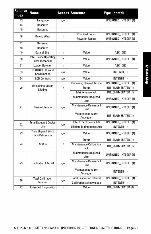
A5E32337708 SITRANS Probe LU (PROFIBUS PA) – OPERATING INSTRUCTIONS Page 63
mm
mm
m
G: Data M
ap
43 Language r/w UNSIGNED_INTEGER (1)
44 Reserved
45 Reserved
46 Device Wear rPowered Hours UNSIGNED_INTEGER (4)
Poweron Resets UNSIGNED_INTEGER (2)
47 Reserved
48 Reserved
49 Date of Birth r Value ASCII (16)
50Total Device Operating
Time (seconds)r Value UNSIGNED_INTEGER (4)
51 Loader Revision r Value ASCII (16)
53PROFIBUS Current
Consumptionr/w Value INTEGER (1)
54 LCD Contrast r/w Value INTEGER (1)
70Remaining Device
Lifetimer
Remaining Device Lifetime UNSIGNED_INTEGER (4)
Status BIT_ENUMERATED (1)
Maintenance ack BIT_ENUMERATED (1)
71 Device Lifetime r/w
Maintenance Required Limit
UNSIGNED_INTEGER (4)
Maintenance Demanded Limit
UNSIGNED_INTEGER (4)
Maintenance Alarm Activation
BIT_ENUMERATED (1)
72Total Expected Device
Lifer/w
Total Expect Device Life UNSIGNED_INTEGER (4)
Lifetime Maintenance Ack INTEGER (1)
73Time Elapsed Since
Last Calibrationr/w Value UNSIGNED_INTEGER (4)
74 Status rStatus BIT_ENUMERATED (1)
Maintenance Calibrationack
BIT_ENUMERATED (1)
75 Calibration Interval r/w
Maintenance Required Limit
UNSIGNED_INTEGER (4)
Maintenance Demanded Limit
UNSIGNED_INTEGER (4)
Maintenance Alarm Activation
INTEGER (1)
76Total Calibration
Intervalr/w
Total Calibration Interval UNSIGNED_INTEGER (4)
Calibration acknowledge INTEGER (1)
77 Extended Diagnostics r Value BIT_ENUMERATED (6)
Relative Index Name Access Structure Type (cont’d)

Page 64 SITRANS Probe LU (PROFIBUS PA) – OPERATING INSTRUCTIONS A5E32337708
mm
mm
m
G: D
ata
Map
Analog Input Function Blocks: AIFB1 and AIFB2Each of the two Analog Input Function Blocks can be set up to return Level, Distance, or Volume. Within the function blocks, the values are scaled according to the user requirement.
Relative Index Name Access Structure Type
0 Block Object r
Reserved UNSIGNED_INTEGER (1)
Block Object INTEGER (1)
Parent Class INTEGER (1)
Class INTEGER (1)
DD Reference UNSIGNED_INTEGER(4)
DD Revision UNSIGNED_INTEGER(2)
Profile INTEGER (2)
Profile Revision INTEGER (2)
Execution time UNSIGNED_INTEGER (1)
Number of Parameters UNSIGNED_INTEGER(2)
Address of View 1 UNSIGNED_INTEGER(2)
Number of views UNSIGNED_INTEGER(1)
1 ST REV r Value UNSIGNED_INTEGER(2)
2 Tag r/w Value ASCII(32)
3 Strategy r/w Value UNSIGNED_INTEGER(2)
4 Alert Key r/w Value UNSIGNED_INTEGER (1)
5 Target Mode r/w Value UNSIGNED_INTEGER (1)
6 Mode Block r
Actual Mode UNSIGNED_INTEGER (1)
Permitted Modes UNSIGNED_INTEGER (1)
Normal Mode UNSIGNED_INTEGER (1)
7Alarm Sum-
maryr/w
Current States UNSIGNED_INTEGER (2)
Unacknowledged UNSIGNED_INTEGER (2)
Unreported UNSIGNED_INTEGER (2)
Disabled UNSIGNED_INTEGER (2)
8Batch Informa-
tionr/w
Batch ID UNSIGNED_INTEGER(4)
Batch Unit UNSIGNED_INTEGER (2)
Batch Operation UNSIGNED_INTEGER(2)
Batch Phase UNSIGNED_INTEGER(2)
10 OUT r/w
Output Value FLOAT (2)
Quality UNSIGNED_INTEGER (1)
Status UNSIGNED_INTEGER (1)
11 PV Range r/wUpper FLOAT (2)
Lower FLOAT (2)

A5E32337708 SITRANS Probe LU (PROFIBUS PA) – OPERATING INSTRUCTIONS Page 65
mm
mm
m
G: Data M
ap
12 Output Scale r/w
Upper FLOAT (2)
Lower FLOAT (2)
Units UNSIGNED_INTEGER(2)
Decimals INTEGER (1)
13Characteriza-
tion Typer/w Value UNSIGNED_INTEGER (1)
14 Function r/w Value UNSIGNED_INTEGER (2)
16Filter Time Con-
stantr/w Value FLOAT (2)
17 Failsafe Mode r/w Value INTEGER (1)
18Failsafe Default
Valuer/w Value FLOAT (2)
19Limit Hystere-
sisr/w Value FLOAT (2)
21Upper Limit
Alarm r/w Value FLOAT (2)
23Upper Limit
Warningr/w Value FLOAT (2)
25Lower Limit
Warningr/w Value FLOAT (2)
27Lower Limit
Alarmr/w Value FLOAT (2)
34 Quality r
Quality INTEGER (1)
Status INTEGER (1)
Simulation Value FLOAT (2)
Simulation Enabled INTEGER (1)
35 Out Unit Text r ASCII(16)
45 Max Out Value r/w FLOAT (2)
46 Min Out Value r/w FLOAT (2)
Relative Index Name Access Structure Type (cont’d)

Page 66 SITRANS Probe LU (PROFIBUS PA) – OPERATING INSTRUCTIONS A5E32337708
mm
mm
m
G: D
ata
Map
Level Transducer Block This is the main transducer block for the device. (A second block is for internal use only.)
Relative Index Name Access Structure Type
0 Block Object r
Profile Parameter UNSIGNED_INTEGER (1)
Block Object INTEGER (1)
Parent Class INTEGER (1)
Class INTEGER (1)
DD Reference UNSIGNED_INTEGER(4)
DD Revision UNSIGNED_INTEGER(2)
Profile INTEGER (2)
Profile Revision INTEGER (2)
Execution Time UNSIGNED_INTEGER (1)
Number of Parameters UNSIGNED_INTEGER(2)
Index of View 1 UNSIGNED_INTEGER(2)
Number of views UNSIGNED_INTEGER(1)
1Static Revision
Numberr Value UNSIGNED_INTEGER(2)
2 Tag r/w Value ASCII(32)
3 Strategy r/w Value UNSIGNED_INTEGER(2)
4 Alert Key r/w Value UNSIGNED_INTEGER (1)
5 Target Mode r/w Value UNSIGNED_INTEGER (1)
6 Mode Block
r Actual Mode UNSIGNED_INTEGER (1)
r/w Permitted Modes UNSIGNED_INTEGER (1)
r/w Normal Mode UNSIGNED_INTEGER (1)
7 Alarm Summary r/w
Current States UNSIGNED_INTEGER (2)
Unacknowledged UNSIGNED_INTEGER (2)
Unreported UNSIGNED_INTEGER (2)
Disabled UNSIGNED_INTEGER (2)
8PV (Level/Volume)
rValue (Level/Volume) FLOAT (2)
Status (Level/Volume) INTEGER (1)
9PV Units (Level/
Volume)r/w Value INTEGER (2)
10Measured Value
(Level)r Value FLOAT (2)
11 Level Units r/w Value UNSIGNED_INTEGER (2)
12 Sensor Value r Value FLOAT (2)
13 Sensor Units r/w Value INTEGER (2)

A5E32337708 SITRANS Probe LU (PROFIBUS PA) – OPERATING INSTRUCTIONS Page 67
mm
mm
m
G: Data M
ap
14 SV1 rLevel FLOAT (2)
Status (Level) INTEGER (1)
15 SV1 Units r/w Value INTEGER (2)
16 SV2 rDistance FLOAT (2)
Status (Distance) INTEGER (1)
17 SV2 Units r/w Value INTEGER (2)
18 Sensor Offset r/w Value FLOAT (2)
19 Calibration Type r/w Value UNSIGNED_INTEGER (1)
20Low Calibration
Pointr/w Value FLOAT (2)
21High Calibration
Pointr/w Value FLOAT (2)
22 Low Level Point r/w Value FLOAT (2)
23 High Level Point r/w Value FLOAT (2)
24 Level Offset r/w Value FLOAT (2)
25Linearization
Typer/w Value INTEGER (1)
26 Diameter r/w Value FLOAT (2)
27Linearization Vol-
umer/w Value FLOAT (2)
28Max. Sensor
Valuer Value FLOAT (2)
29Min. Sensor
Valuer Value FLOAT (2)
30Max Measured
Valuer/w Value FLOAT (2)
31Min Measured
Valuer/w Value FLOAT (2)
32Process Temper-
aturer Value FLOAT (2)
33Temperature
Unitsr/w Value INTEGER (2)
34Max Process Temperature
r/w Value FLOAT (2)
35Min Process Temperature
r/w Value FLOAT (2)
36Temperature
Sourcer/w Value INTEGER (1)
Relative Index Name Access Structure Type (cont’d)

Page 68 SITRANS Probe LU (PROFIBUS PA) – OPERATING INSTRUCTIONS A5E32337708
mm
mm
m
G: D
ata
Map
37Fixed
Temperature r/w Value FLOAT (2)
53 SV3r/w Value FLOAT (2)
r/w Status UNSIGNED_INTEGER (1)
54 SV3 Units r/w Value UNSIGNED_INTEGER (2)
65 Basic setup r/w
Transducer INTEGER (2)
Algorithm INTEGER (1)
Response Rate INTEGER (1)
66 Echo r/wEcho Lock INTEGER (1)
Echo Marker UNSIGNED_INTEGER (1)
67 TVT Hover Level r/w INTEGER (1)
68Confidence Threshold
r/wThreshold Long UNSIGNED_INTEGER (1)
Threshold Short UNSIGNED_INTEGER (1)
69 Echo Information r
Echo Confidence Long UNSIGNED_INTEGER (1)
Echo Strength UNSIGNED_INTEGER (1)
Echo Confidence Short UNSIGNED_INTEGER (1)
70 r
Noise Average INTEGER (1)
Peak Noise INTEGER (1)
Min Noise INTEGER (1)
72 LOE Timeout r/w FLOAT (2)
73 Rate Limits r/wFill Rate Limit FLOAT (2)
Empty Rate Limit FLOAT (2)
74 Reserved r
75 Reserved r/w FLOAT (2)
76 Simulation r/w
Simulation Value FLOAT (2)
Ramp Start FLOAT (2)
Ramp End FLOAT (2)
Ramp Number of Steps UNSIGNED_INTEGER (2)
Ramp Step Length UNSIGNED_INTEGER (2)
Simulation INTEGER (1)
77 Auto TVT r/wMode INTEGER (1)
Range FLOAT (2)
78 Reserved r FLOAT (2)
78 Reserved r FLOAT (2)
79 Number of shots r/wLong shots INTEGER (1)
Short shots INTEGER (1)
80 Reserved r/w INTEGER (1)
Relative Index Name Access Structure Type (cont’d)

A5E32337708 SITRANS Probe LU (PROFIBUS PA) – OPERATING INSTRUCTIONS Page 69
mm
mm
m
G: Data M
ap
81 Breakout point 1 r/wLevel 1 FLOAT (2)
Volume 1 FLOAT (2)
82 Breakout point 2 r/wLevel 2 FLOAT (2)
Volume 2 FLOAT (2)
83 Breakout point 3 r/wLevel 3 FLOAT (2)
Volume 3 FLOAT (2)
84 Breakout point 4 r/wLevel 4 FLOAT (2)
Volume 4 FLOAT (2)
85 Breakout point 5 r/wLevel 5 FLOAT (2)
Volume 5 FLOAT (2)
86 Breakout point 6 r/wLevel 6 FLOAT (2)
Volume 6 FLOAT (2)
87 Breakout point 7 r/wLevel 7 FLOAT (2)
Volume 7 FLOAT (2)
88 Breakout point 8 r/wLevel 8 FLOAT (2)
Volume 8 FLOAT (2)
89 Breakout point 9 r/wLevel 9 FLOAT (2)
Volume 9 FLOAT (2)
90 Breakout point 10 r/wLevel 10 FLOAT (2)
Volume 10 FLOAT (2)
91Breakout point
11r/w
Level 11 FLOAT (2)
Volume 11 FLOAT (2)
92 Profile setup r DB Start y INTEGER (1)
r DB End y INTEGER (1)
r X Length INTEGER (1)
r Distance FLOAT (2)
r End x FLOAT (2)
r Step x FLOAT (2)
r Meas x FLOAT (2)
r Step x TVT FLOAT (2)
r Echo Marker UNSIGNED_INTEGER
93Profile data part
1r Value byte array
94Profile data part
2r Value byte array
95Profile data part
3r Value byte array
Relative Index Name Access Structure Type (cont’d)

Page 70 SITRANS Probe LU (PROFIBUS PA) – OPERATING INSTRUCTIONS A5E32337708
mm
mm
m
G: D
ata
Map
96Profile data part
4r Value byte array
97Profile data part
5r Value byte array
98Profile data part
6r Value byte array
99 TVT data part 1 r Value byte array
100 TVT data part 2 r Value byte array
130 Sound Velocity r FLOAT (2)
131Sound Velocity at
20 °Cr/w FLOAT (2)
132 Tank shape r/wDim A FLOAT (2)
Dim L FLOAT (2)
133TVT Shaper
Moder/w INTEGER (1)
134 Shaper Array r/w
Point 1 INTEGER (1)
Point 2 INTEGER (1)
Point 3 INTEGER (1)
Point 4 INTEGER (1)
Point 5 INTEGER (1)
Point 6 INTEGER (1)
Point 7 INTEGER (1)
Point 8 INTEGER (1)
Point 9 INTEGER (1)
Point 10 INTEGER (1)
Point 11 INTEGER (1)
Point 12 INTEGER (1)
Point 13 INTEGER (1)
Point 14 INTEGER (1)
Point 15 INTEGER (1)
Point 16 INTEGER (1)
Point 17 INTEGER (1)
Point 18 INTEGER (1)
Point 19 INTEGER (1)
Point 20 INTEGER (1)
Point 21 INTEGER (1)
Relative Index Name Access Structure Type (cont’d)
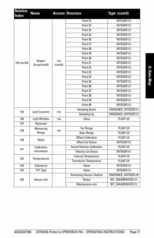
A5E32337708 SITRANS Probe LU (PROFIBUS PA) – OPERATING INSTRUCTIONS Page 71
mm
mm
m
G: Data M
ap
134 (cont’d)Shaper
Array(cont’d)r/w
(cont’d)
Point 22 INTEGER (1)
Point 23 INTEGER (1)
Point 24 INTEGER (1)
Point 25 INTEGER (1)
Point 26 INTEGER (1)
Point 27 INTEGER (1)
Point 28 INTEGER (1)
Point 29 INTEGER (1)
Point 30 INTEGER (1)
Point 31 INTEGER (1)
Point 32 INTEGER (1)
Point 33 INTEGER (1)
Point 34 INTEGER (1)
Point 35 INTEGER (1)
Point 36 INTEGER (1)
Point 37 INTEGER (1)
Point 38 INTEGER (1)
Point 39 INTEGER (1)
Point 40 INTEGER (1)
135 Lock Counters r/wSampling Down UNSIGNED_INTEGER (1)
Sampling Up UNSIGNED_INTEGER (1)
136 Lock Window r/w Value FLOAT (2)
137 Reserved
139Measuring
Ranger/w
Far Range FLOAT (2)
Near Range FLOAT (2)
140 OffsetOffset Calibration FLOAT (2)
Offset Cal Status INTEGER (1)
141Calibrationinformation
Sound Velocity Calibration FLOAT (2)
Velocity Cal Status INTEGER (1)
142 TemperaturesInternal Temperature FLOAT (2)
Transducer Temperature FLOAT (2)
143 Substance Value INTEGER (1)
144 TVT Type Value INTEGER (1)
153 Sensor Life
Remaining Sensor Lifetime UNSIGNED_INTEGER (4)
Status BIT_ENUMERATED (1)
Maintenance ack BIT_ENUMERATED (1)
Relative Index Name Access Structure Type (cont’d)

Page 72 SITRANS Probe LU (PROFIBUS PA) – OPERATING INSTRUCTIONS A5E32337708
mm
mm
m
G: D
ata
Map
154 Device Lifetime
Maintenance Required Limit UNSIGNED_INTEGER (4)
Maintenance Demanded Limit UNSIGNED_INTEGER (4)
Maintenance Alert Activation BIT_ENUMERATED (1)
155 Sensor Life
Total Expected Sensor Life UNSIGNED_INTEGER (4)
Total Sensor Operating Time UNSIGNED_INTEGER (4)
Lifetime maintenance ack INTEGER (1)
156Time Elapsed
Since Last Ser-vice
Value UNSIGNED_INTEGER (4)
157 StatusStatus BIT_ENUMERATED (1)
Service maintenance ack BIT_ENUMERATED (1)
158Calibration
Interval
Maintenance Required Limit UNSIGNED_INTEGER (4)
Maintenance Demanded Limit UNSIGNED_INTEGER (4)
Maintenance Alert Activation INTEGER (1)
159 Service IntervalTotal Service Interval UNSIGNED_INTEGER (4)
Service ack INTEGER (1)
Relative Index Name Access Structure Type (cont’d)

A5E32337708 SITRANS Probe LU (PROFIBUS PA) – OPERATING INSTRUCTIONS Page 73
mm
mm
m
H: Param
eters
Appendix H: Parameter Descriptions
SITRANS Probe LU (PROFIBUS PA): parameter menus The parameters are grouped in menus according to function. Submenus, arranged on four levels, give access to associated features and options.
Some menus are accessible in PDM only via pull-down menus: in those cases, directions are given beside the individual parameter.
Not all menus are accessible via the handheld programmer. Menus that are accessible via the handheld programmer are preceded by a number (applicable only to the handheld programmer).
1. Identification Operation Unit
TagText that can be used in any way, for example as a unique label for a field device in the plant.
DescriptionText that is associated with the Field Device. This text can be used by the user in any way. There is no specific recommended use.
MessageText that is associated with the FIeld Device. This text can be used by the user in any way. There is no specific recommended use.
1.2. Configuration1.2.1. Device Address (default 126)
The unique address of the device on the network (also called PROFIBUS address).
Open the menu Device – Set Address.
Notes: • For Quick Access to parameters via the handheld programmer, press the mode key
to activate PROGRAM mode, then key in the menu number. (For more details, see The handheld programmer on page 17.)
• Values shown in the tables below can be entered via the handheld programmer.• Default values are indicated by an asterisk (*) in the tables, unless explicitly stated.
Values 0 - 126

Page 74 SITRANS Probe LU (PROFIBUS PA) – OPERATING INSTRUCTIONS A5E32337708
mm
mm
m
H: P
aram
eter
s1.2.2. Remote Lockout
Use the handheld programmer to enable or disable programming via the network and PDM.
1.2.3. Factory Reset
Open the menu Device – Master Reset and select one of the four options.
1.2.4. Reset FaultResets the Fault message after an active fault has occurred and been corrected. A manual reset is required only for the following faults:
Open the menu View – Clear Faults, and select the fault in question from the pull-down menu for Extended Diagnostics.
(To reset via the handheld programmer, key in the value of the fault code in question.)
1.2.5. Menu Timeout (default 120 s)Determines the length of time (in seconds) the device will stay in PROGRAM mode without any key presses occurring.
1.3. DeviceManufacturer
References a specific manufacturer, usually the name of the company responsible for the manufacture of this Field Device.
Hand programmer values
0 * Unlocked
1 Locked
Note: Following a Master Reset, complete reprogramming is required.
Hand programmer values
1 Reset all parameters (except PROFIBUS address) to PROFIBUS PA profile default values
2506 Warm Start: restart the device (this option is rarely used)
2712 Reset PROFIBUS address to 126
32768 Reset to manufacturer’s default values (factory settings)
Hand programmer values
12 Internal temperature high
Transducer temperature high
Transducer temperature low

A5E32337708 SITRANS Probe LU (PROFIBUS PA) – OPERATING INSTRUCTIONS Page 75
mm
mm
m
H: Param
etersProduct designation
Uniquely identifies the Field Device when combined with the Manufacturer Identification and Device Type. This variable cannot be modified by the Host user.
Device Serial NumUniquely identifies the Field Device. This variable cannot be modified by the Host.
Order No.The order number for this device.
Date of birthDate of manufacture.
1.3.1. Software RevisionCorresponds to the firmware embedded in the Field Device.
1.3.2. Loader RevisionCorresponds to the firmware used to update the Field Device.
1.3.3. Hardware RevisionCorresponds to the electronics hardware of the Field Device.
Profile RevisionPROFIBUS PA Profile standard that this device conforms to.
Static Revision No. The revision level of the static data associated with the Physical Block. The Static Revision No. is updated whenever a standard profile configuration parameter is changed.
1.3.4. PROFIBUS Ident NumberIdentifies the device on the network. The Ident Number must match that in the GSD file (the GSD file provides information on the device to the master).
Installation DateDate on which the device was installed. The user must enter the date.
Local Operation Enable (default Enabled)Enables/disables programming the device via the handheld programmer.When disabled, the user still has access to the mode control of the two Analog Input Function Blocks.Go to Identification > Device > Local Operation Enable and select the desired setting.
Hand programmer values
0 Profile-specific [uses generic GSD for 2 AIFB (ident# = x9701)]
1 *Manufacturer-specific (uses SMPI DD and GSD file, which identifies the Probe LU [PROFIBUS PA]).
128 Profile-specific [uses generic GSD for 1 AIFB (ident# = x9700)]

Page 76 SITRANS Probe LU (PROFIBUS PA) – OPERATING INSTRUCTIONS A5E32337708
mm
mm
m
H: P
aram
eter
s1.3.5. Write Locking
Prevents any changes to parameters via PDM or the handheld programmer.
Open the menu Device – Write Locking, and select On or Off.
1.3.6. ContrastAllows you to adjust the LCD contrast to compensate for different lighting conditions.
Go to Identification > Device > Contrast, and enter the desired value. To increase the contrast, enter a higher value.
1.3.7. LanguageSelects the language to be used on the LCD.
1.4. Statistics1.4.1. Powered Hours
Number of hours the unit has been powered up since manufacture.Open menu View – Wear.
1.4.2. Poweron ResetsThe number of power cycles that have occurred since manufacture.Open menu View – Wear.
1.4.3. Internal TemperatureThe internal electronics temperature.
Open menu View – Peak Values, and select the tab Temperature.
Hand programmer values
2457 (unlock value) * Off (enables programming)
any other value On (disables programming)
ValuesRange: 0 to 10
Default: 3
Hand programmer values
0 * English
1 German
2 French
3 Spanish
Value (view only) Degrees C

A5E32337708 SITRANS Probe LU (PROFIBUS PA) – OPERATING INSTRUCTIONS Page 77
mm
mm
m
H: Param
eters1.4.4. Transducer Temperature
The temperature inside the tank (process temperature) registered by the transducer.
Open menu View – Display, and select the tab Measured Value (Secondary Values).
2. Input Static Revision Number
The revision level of the static data associated with the Transducer Block, updated whenever a standard profile configuration parameter is changed.
ClassIndicates the Level Transducer Block as per PROFIBUS PA Profile specifications.
2.1. Target Mode
Visible only via the handheld programmer. Used to request an operating mode from the Transducer Block. (Out-of-service mode is a safety feature, used for service purposes to stop the transducer firing).
2.2. Reset FilterResets the rate filter.
Value (view only) Degrees in Temperature Units
Note: If Target Mode has been changed locally and you want to prevent an external process from resetting it back to normal, you should ensure Remote Lockout (see page 74) is set to Locked.
Hand programmer values
128 Out of Service (O/S)
16 Manual Mode (MAN)
8 * Automatic Mode (AUTO)
Hand programmer value
1the sensor value immediately goes to the target distance

Page 78 SITRANS Probe LU (PROFIBUS PA) – OPERATING INSTRUCTIONS A5E32337708
mm
mm
m
H: P
aram
eter
s
2.3. Standard Setup2.3.1. Response Rate
Sets the reaction speed of the device to measurement changes in the target range.12
Use a setting just faster than the maximum filling or emptying rate (whichever is greater). Slower settings provide higher accuracy: faster settings allow for more level fluctuation.
2.3.2. Echo Lock
Selects the measurement verification process.
If a material agitator or mixer is used in the monitored vessel, Echo Lock should be set for Maximum Verification or Material Agitator to avoid agitator blade detection.
Related para-meters
ResponseRate
LOE Timer1 (minutes)
Fill Rate Empty Rate
Echo Lock2
Hand programmer values
1 * slow 100 0.1 m/minute 0.1 m/minute
2material agitator
2 medium 10 1 m/minute 1 m/minute
3 fast 1 10 m/minute 10 m/minute
Note: Changing Response Rate resets the following parameters: LOE Timer, Fill Rate, Empty Rate, and Echo Lock.
1. For more detail, see LOE Timer on page 36.2. For more detail, see Echo Lock on page 35.
Note: Ensure the agitator is always running while SITRANS Probe LU is monitoring the vessel, to avoid stationary blade detection.
Hand programmer values
0 Off
1 Maximum Verification
2 * Material Agitator
3 Total Lock
Related parameters
Maximum Fill RateMaximum Empty RateEcho Lock SamplingEcho Lock WindowAlgorithm

A5E32337708 SITRANS Probe LU (PROFIBUS PA) – OPERATING INSTRUCTIONS Page 79
mm
mm
m
H: Param
eters2.3.3. Temperature Source1
Determines the source of the temperature reading used for calculating speed of sound. There are two options:
2.3.4. Fixed Temperature1 (default 20 oC)Defines the fixed temperature (in degrees C) used for calculating speed of sound (see above).
2.3.5. PROFIBUS Current Consumption
Allows you to select the PROFIBUS device current. Higher values allow faster update rates.2
Go to Input > Standard Setup > PROFIBUS Current Consumption, and enter the value corresponding to the desired device current.
1. This parameter cannot be reset to factory default settings.
Hand programmer values
Fixed Temperature (user-defined value: see below)
* Automatic default value (recorded by sensor inside the trans-ducer)
Values Range, Degrees C
Warning: This parameter should be modified only once at installation, to match the design criteria of the network.
Values Loop current Update Time2
0 * 12 mA 6.0 s (typical), maximum 16.0 s
1 13 mA 5.0 s (typical), maximum 14.0 s
2 15 mA 3.7 s (typical), maximum 8.0 s
3 20 mA 2.4 s (typical), maximum 4.0 s
2. Temperature dependent: typical values at +20 °C (+68 °F); maximum values at +80 ° C (+176 °F).

Page 80 SITRANS Probe LU (PROFIBUS PA) – OPERATING INSTRUCTIONS A5E32337708
mm
mm
m
H: P
aram
eter
s
2.4. Sensor Calibration12
2.4.1. Sensor UnitsWhatever units the sensor is measuring in. 3
2.4.2. Calibration TypeIn Dry calibration, the user enters all four calibration values: High and Low Level Points, and High and Low Calibration Points. In Wet calibration, the actual material level provides the values for Low Calibration and High Calibration Points. The user enters the corresponding Low and High Level Points.
Open the menu Device – Sensor Calibration, and click on the button for Wet or Dry calibration.
1. Sensor Reference Point: the point to which all of the above parameters are refer-enced, which is the transducer face.
2. Sensor Value: the value produced by the echo processing, which represents the dis-tance from the Sensor Reference Point to the target.
3. Level Value: the level measured in level units.
Hand programmer values
0 * Dry calibration (preferred)
1 Wet calibration
High Level Point(default: 100%)
Sensor Reference Point1 (transducer face)
Sensor Value2
Level3
Level OffsetSecondary Value 1
Low Calibration Point
Sensor Offset
High Calibration Point
Low Level Point(default: 0%)
Tank Reference Point
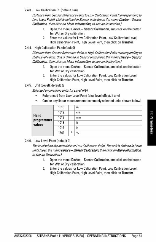
A5E32337708 SITRANS Probe LU (PROFIBUS PA) – OPERATING INSTRUCTIONS Page 81
mm
mm
m
H: Param
eters2.4.3. Low Calibration Pt. (default 6 m)
Distance from Sensor Reference Point to Low Calibration Point (corresponding to Low Level Point). Unit is defined in Sensor units (open the menu Device – Sensor Calibration, then click on More Information, to see an illustration.)
1. Open the menu Device – Sensor Calibration, and click on the button for Wet or Dry calibration.
2. Enter the values for Low Calibration Point, Low Calibration Level, High Calibration Point, High Level Point, then click on Transfer.
2.4.4. High Calibration Pt. (default 0)Distance from Sensor Reference Point to HIgh Calibration Point (corresponding to High Level Point). Unit is defined in Sensor units (open the menu Device – Sensor Calibration, then click on More Information, to see an illustration.)
1. Open the menu Device – Sensor Calibration, and click on the button for Wet or Dry calibration.
2. Enter the values for Low Calibration Point, Low Calibration Level, High Calibration Point, High Level Point, then click on Transfer.
2.4.5. Unit (Level): default %Selected engineering units for Level (PV).
• Referenced from Low Level Point (plus level offset, if any) • Can be any linear measurement (commonly selected units shown below)
2.4.6. Low Level Point (default 0)The level when the material is at Low Calibration Point. The unit is defined in Level units (open the menu Device – Sensor Calibration, then click on More Information, to see an illustration.)
1. Open the menu Device – Sensor Calibration, and click on the button for Wet or Dry calibration.
2. Enter the values for Low Calibration Point, Low Calibration Level, High Calibration Point, High Level Point, then click on Transfer.
Hand programmer values
1010 m
1012 cm
1013 mm
1018 ft
1019 in
1342 * %

Page 82 SITRANS Probe LU (PROFIBUS PA) – OPERATING INSTRUCTIONS A5E32337708
mm
mm
m
H: P
aram
eter
s2.4.7. High Level Point (default 100)
The level when the material is at High Calibration Point. The unit is defined in Level units (open the menu Device – Sensor Calibration, then click on More Information, to see an illustration.)
1. Open the menu Device – Sensor Calibration, and click on the button for Wet or Dry calibration.
2. Enter the values for Low Calibration Point, Low Calibration Level, High Calibration Point, High Level Point, then click on Transfer.
2.4.8. Level Offset (default 0)A constant offset that is added to Level to form SV1 (Secondary Value 1). The unit is defined in Level units.Level Offset is used to compensate for specific tank configurations.
2.4.9. Sensor Offset (default 0)
The offset from the Sensor’s reference point to the tank’s reference point:. If sensor offset is used, it is a negative value that is subtracted from the values for the high and low calibration points. The unit is defined in Sensor Units.Compensates, for example if the sensor head is changed.
2.4.A. Temperature UnitsSelects the engineering unit to be displayed with the value representing temperature.
2.5. Measuring Limits2.5.1. Min. Measured Value
The minimum recorded Sensor value, defined in Sensor units.Open menu View – Peak Values, and click Sensor tab.
2.5.2. Max. Measured ValueThe maximum recorded Sensor value, defined in Sensor units.Open menu View – Peak Values, and click Sensor tab
Note: If a velocity calibration is performed after the sensor offset value has been set manually, the sensor offset value will be reset to 0.
Hand programmer values
1034 Degrees K
1001 * Degrees C
1002 Degrees F
1003 Degrees R

A5E32337708 SITRANS Probe LU (PROFIBUS PA) – OPERATING INSTRUCTIONS Page 83
mm
mm
m
H: Param
eters2.5.3. Min. Sensor Value (default 0.25 m)
Defines the minimum usable value for the measuring range (physical limit of the sensor) in Sensor units.
Open menu View – Peak Values and select the tab AIFB1 or AIFB2. If necessary, click on the reset button, and download to the device.
2.5.4. Max. Sensor Value (6 m or 12 m, depending on unit)Defines the maximum usable value for the measuring range (physical limit of the sensor) in Sensor units.Open menu View – Peak Values and select the tab AIFB1 or AIFB2. If necessary, click on the reset button, and download to the device.
2.5.5. Process Temperature Min.The minimum recorded temperature of the internal electronics.Open menu View – Peak Values and select the tab Temperature. If necessary, click on the reset button, and download to the device.
2.5.6. Process Temperature Max.The maximum recorded temperature of the internal electronics.Open menu View – Peak Values and select the tab Temperature. If necessary, click on the Reset button, and download to the device.
2.6. LinearizationCarries out a volume conversion from a level value.
2.6.1. PV (volume/level) Units (default %)Select units for either volume or level.
2.6.2. Linearization Type/Tank Shape (default None)Defines the tank shape and allows the Probe LU to calculate volume instead of level. If None is selected, no volume conversion is performed. Select the tank shape matching the monitored tank or reservoir (see table on next page).
Hand programmer values
1010 m
1012 cm
1012 mm
1018 ft
1019 in
1342 * %
1034 m3
1038 L
1042 ft3
1043 in3
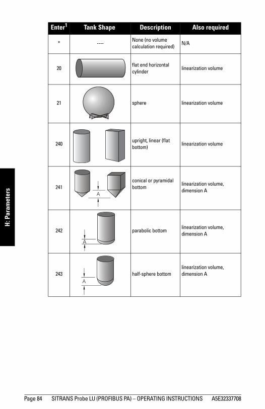
Page 84 SITRANS Probe LU (PROFIBUS PA) – OPERATING INSTRUCTIONS A5E32337708
mm
mm
m
H: P
aram
eter
s
Enter1 Tank Shape Description Also required
* ----None (no volume calculation required)
N/A
20flat end horizontal cylinder
linearization volume
21 sphere linearization volume
240upright, linear (flat bottom)
linearization volume
241conical or pyramidal bottom
linearization volume, dimension A
242 parabolic bottomlinearization volume, dimension A
243 half-sphere bottomlinearization volume, dimension A
A
A
A

A5E32337708 SITRANS Probe LU (PROFIBUS PA) – OPERATING INSTRUCTIONS Page 85
mm
mm
m
H: Param
eters
2.6.3. Linearization Volume (default 100.0)The maximum volume of the tank. Units are defined in Primary Value units. Any volumetric units can be chosen, because the volume calculation is based on the maximum volume, and scaled according to the vessel shape selected. If no vessel shape is entered, the default is 100, and the reading will be a percentage value.
For readings in volumetric units instead of percentage values, enter the vessel volume corresponding to High Calibration Point.
2.6.4. Dimension A (default 0.0)The height of the vessel bottom (in level units) when the bottom is conical, pyramidal, parabolic, spherical, flat sloped, cylindrical, or spherical. See page 84 for an illustration.
1. Go to Input > Sensor Calibration > Unit (level) and select desired level units.
2. Key in the height of the vessel bottom in level units.
244 flat sloped bottom linearization volume, dimension A
245parabolic end horizontal cylinder
linearization volume, dimension A, dimension L
247universal linear(level/volume/flow breakpoints)
linearization volume (flow), level (head) breakpoints, volume (flow) breakpoints
1. Enter handheld programmer value.
Hand programmer values Range: 0.0000 to 99999
Related Parameters Low Calibration PointHigh Calibration Point
Hand programmer values Range: 0.0000 to 99999 in units (P005)
Related Parameters Tank Shape
Enter1 Tank Shape (cont’d) Description Also required
A
A L

Page 86 SITRANS Probe LU (PROFIBUS PA) – OPERATING INSTRUCTIONS A5E32337708
mm
mm
m
H: P
aram
eter
s2.6.5. Dimension L (default 0.0)
Length of the cylindrical section of a horizontal parabolic end tank, in level units. See page 85 for an illustration.
1. Go to Input > Sensor Calibration > Unit (level) and select desired level units.
2. Key in the height of the vessel bottom in level units.
2.7. Detailed Setup2.7.1. Failsafe
2.7.1.1. LOE (Loss of Echo) Timer (default 10)Amount of time, in minutes, that a Loss of Echo must persist, before the device goes into Failsafe mode. See page 36 for more details.
2.7.2. VolumeWhen the vessel shape is too complex for any of the preconfigured shapes, you can define the shape as a series of segments. First assign a value to each level breakpoint, then assign a corresponding value to each volume breakpoint. (Volume values can be percent or volumetric; level values can be percent or linear.)
Enter up to 32 level breakpoints, where the corresponding volume is known. The values corresponding to 100% and 0% levels must be entered. The breakpoints can be ordered from top to bottom, or the reverse. Breakpoints are normalized to 0.
Hand programmer values Range: 0.0000 to 99999 in units (P005)
Related Parameters Tank Shape
Hand programmer values Range: 0.00 to 720 (minutes)
Level ValuesRange: 0.0000 to 99999 (%, ft, m, in, cm, mm, gal, L, imp. gal: see PDM for more)
Default: 0.0
Volume ValuesRange: 0.0000 to 99999 (% or volumetric units)
Default: 0.0

A5E32337708 SITRANS Probe LU (PROFIBUS PA) – OPERATING INSTRUCTIONS Page 87
mm
mm
m
H: Param
etersEntering breakpoints in PDM:a. First go to Linearization > PV (volume/level) units, and select the
desired volume units.b. The default for level values is percent: if you want to select units
instead, go to Input > Sensor Calibration > Unit (level), and select the desired unit.
c. Go to > Linearization/Tank Shape, and select Linearization table option.
d. Go to Detailed Setup > Volume.e. In Level 1, enter a level value for breakpoint 1 (point 1 should always
be 0).f. In Volume 1, enter the corresponding volume value for breakpoint 1
(point 1 should always be 0).g. Repeat steps c and d until values have been entered for all the
required breakpoints.The highest level and volume values should correspond to the maximum volume setting or 2.4.7 (High Level Pt)
Example:
FlowThe level and volume breakpoints can be also be used to calculate head level and flow rate in an open channel device. (For more information please see Open Channel Monitoring (OCM) on page 39.)Use the level breakpoints to enter head level values, and the volume breakpoints to enter flow volumes. Each segment defined by a head breakpoint requires a corresponding flow value, so that SITRANS Probe LU can make the head-to-flow calculations.Use the Flow table associated with your open channel device (Parshall flume, v-notch weir, or other measuring device) to calculate the flow rate for each breakpoint.
Note: Changing 2.4.7 (High Level Point) after programming the level/volume points will change the level setting and proportionally increase or decrease the volume values at the new level setting.
Note: Breakpoint values are for example purposes only.
4 20
9
5
0
Breakpoint number
32
1
Breakpoint Number
Level value(m)
Volume value(l)
1 0 0
2 5 500
3 9 3000
4 20 8000
Level value
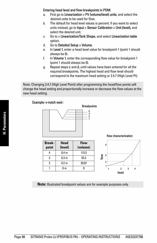
Page 88 SITRANS Probe LU (PROFIBUS PA) – OPERATING INSTRUCTIONS A5E32337708
mm
mm
m
H: P
aram
eter
sEntering head level and flow breakpoints in PDM:a. First go to Linearization > PV (volume/level) units, and select the
desired units to be used for flow.b. The default for head level values is percent: if you want to select
units instead, go to Input > Sensor Calibration > Unit (level), and select the desired unit.
c. Go to > Linearization/Tank Shape, and select Linearization table option.
d. Go to Detailed Setup > Volume.e. In Level 1, enter a head level value for breakpoint 1 (point 1 should
always be 0).f. In Volume 1, enter the corresponding flow value for breakpoint 1
(point 1 should always be 0).g. Repeat steps c and d, until values have been entered for all the
required breakpoints. The highest head and flow level should correspond to the maximum head setting or 2.4.7 (High Level Pt).
Example: v-notch weir:
Note: Changing 2.4.7 (High Level Point) after programming the head/flow points will change the head setting and proportionally increase or decrease the flow values at the new head setting.
Note: Illustrated breakpoint values are for example purposes only.
4
Breakpoints
32
Break-point
Head (level)
Flow (volume)
4 0.4 m 113.5
3 0.3 m 55.3
2 0.2 m 20.07
1 0 m 0
1
flow characterization
4
2
1
3
421 3
head
flow

A5E32337708 SITRANS Probe LU (PROFIBUS PA) – OPERATING INSTRUCTIONS Page 89
mm
mm
m
H: Param
eters2.7.3. Echo select
2.7.3.1. AlgorithmSelects the algorithm to be applied to the echo profile to extract the true echo.
2.7.3.2. Threshold Short (default 10)
Sets the minimum Short Shot echo confidence that the echo must meet in order to be considered a valid echo.
2.7.3.3. Threshold Long (default 5)Sets the minimum Long Shot echo confidence that the echo must meet in order to be considered a valid echo.
2.7.3.4. Echo Marker (default 50)The point on the selected echo from which the measured value is taken.
2.7.3.5. Short Shots (default 2)The number of Short Shots transmitted and averaged per measurement cycle.
2.7.3.6. Long Shots (default 2)The number of Long Shots transmitted and averaged per measurement cycle.
Hand programmer values
12 tF
3 LLargest echo (reserved for SMPI service personnel)
4 F First echo
8 * bLFbest of Largest or First echo (reserved for SMPI service personnel)
Note: The Threshold parameters are for use by authorized Siemens Service personnel or technicians familiar with Siemens echo processing techniques.
Hand programmer values Range: 0 to 99
Related Parameters LOE Timer
Hand programmer values Range: 0 to 99
Related Parameters LOE Timer

Page 90 SITRANS Probe LU (PROFIBUS PA) – OPERATING INSTRUCTIONS A5E32337708
mm
mm
m
H: P
aram
eter
s2.7.3.8. Sound Velocity at 20 oC (default 344.13)
Sound velocity through the medium at 20 oC. (Sound velocity in air is 344.1 m/s or 1129 ft/s.)
2.7.3.9. Offset and Velocity calibration1. Offset calibration
You can specify a fixed value to apply to all measurements. Use this function if the reported level is consistently high or low by a fixed amount (stored in Sensor Offset).
Open menu Device – Offset and Velocity Calibration, select the option to change calibration, select the calibration type, then enter new calibration value.
2. Sound Velocity calibration
Used to calculate sound velocity when either the acoustic beam environment is other than air or unknown, or the reading accuracy is acceptable only at higher material level. For best results, calibrate with the level at a known value close to empty, and manually determine the actual distance from sensor to material level.
Open menu Device – Offset and Velocity Calibration, select the option to change calibration, select the calibration type, then enter new calibration value.
2.7.4. Echo Sampling
2.7.4.1. Sampling up1 (default 5)Once echo is outside the window, a specified number of consecutive echoes must appear above the echo locked onto, before measurement is accepted as valid.
Note: If a velocity calibration is performed after the sensor offset value has been set manually, the sensor offset value will be reset to 0.
Note: The Echo Sampling parameters are for use by authorized Siemens Service personnel or technicians familiar with Siemens echo processing techniques.
1. This parameter is for use only by Siemens service technicians.

A5E32337708 SITRANS Probe LU (PROFIBUS PA) – OPERATING INSTRUCTIONS Page 91
mm
mm
m
H: Param
eters2.7.4.2. Sampling down1 (default 2)
Once echo is outside the window, a specified number of consecutive echoes must appear below the echo locked onto, before measurement is accepted as valid.
2.7.4.3. Window1 (default 0)A "distance window" centered on the echo, used to derive the reading. When a new measurement is in the window, the window is re-centered and the reading is calculated (see Display before Auto False Echo Suppression on page 94 for an illustration).
When the value is 0, the window is automatically calculated after each measurement.
• For slower Measurement Response values, the window is narrow.• For faster Measurement Response values, the window becomes
progressively wider.
2.7.4.4. Window Used1
The actual size of the window (whereas Window refers to the designed size of the window.
2.7.5. Range2.7.5.1. Near Range (LOW RANGE): (default value 0.25 m)
Minimum distance from the reference point2 beyond which an echo should be considered valid. (This is sometimes referred to as Blanking.)
2.7.5.2. Far Range (HI RANGE): (default 6 m or 12 m, depending on unit)
Maximum distance from the reference point2, within which an echo should be considered valid.
1. This parameter is for use only by Siemens service technicians.
Note: The echo lock window is stored as standard sample, but displayed in the engineering units selected to display level. Any value entered for the echo lock window will be rounded to the nearest sample.
2. The transducer face.
Hand programmer values Range: 0 to 20 m
Note: Far Range can extend beyond the bottom of the tank.
Hand programmer values Range: 0 to 20 m

Page 92 SITRANS Probe LU (PROFIBUS PA) – OPERATING INSTRUCTIONS A5E32337708
mm
mm
m
H: P
aram
eter
s2.7.6. Echo Quality
2.7.6.1. Confidence ShortShort shot confidence value displays the echo confidence of the measurements echo from the last short shot. Echo confidence measures echo reliability. Threshold Short defines the minimum criterion for short shot echo confidence.
Open the menu View – Profile.
2.7.6.2. Confidence LongLong shot confidence value displays the echo confidence of the measurements echo from the last long shot. Echo confidence measures echo reliability. Threshold Long defines the minimum criterion for long shot echo confidence.
Open the menu View – Profile.
2.7.6.3. Echo StrengthDisplays the amplitude (in dB above 1 μV rms) of the echo selected as the measurement echo.
Open the menu View – Profile.
Values (view only)0 to 99---- Shot not used
Related Parameters
Threshold Short
Values (view only)0 to 99---- Shot not used
Related Parameters
Threshold Long
Values (view only) –20 to 112

A5E32337708 SITRANS Probe LU (PROFIBUS PA) – OPERATING INSTRUCTIONS Page 93
mm
mm
m
H: Param
eters2.7.7. TVT setup
First SITRANS Probe LU learns the echo profile. Then the learned profile, or part of the learned profile, is used to screen out false echoes.
2.7.7.1. TVT Hover Level1 (default 33%)Defines in percent how high the TVT (Time Varying Threshold) curve is placed above the echo profile, with respect to largest echo. When SITRANS Probe LU is located in the center of the vessel, lower this parameter to prevent multiple echo detections.
2.7.7.2. TVT TypeSelects the TVT curve to be used.
2.7.7.7. Auto False Echo Suppression Enables a ’learned’ TVT curve to be used in place of the default TVT curve.
Use this feature to ignore false echoes on the echo profile. Set Range
(Auto False Echo Suppression Distance) first.
a. Rotate the instrument for best signal (lower false-echo amplitude).b. Go to Range, and set the value (see page 94).c. Open the menu Device – Auto False Echo Suppression and select
the option to change it.d. Select Learn. The device will automatically revert to On (Use
Learned TVT) after a few seconds.
1. For an illustration, see Display before Auto False Echo Suppression and Display after Auto False Echo Suppression, on page 94.
Values Range: 0 to 100%
Hand programmer values
1 * TVT short curve
2 TVT short flat
3 TVT long flat
4 TVT long smooth flat
5 TVT long smooth
6 TVT slopes
Hand programmer values
0 * Off
1 On
2 Learn the TVT curve

Page 94 SITRANS Probe LU (PROFIBUS PA) – OPERATING INSTRUCTIONS A5E32337708
mm
mm
m
H: P
aram
eter
s2.7.7.8. Range (Auto False Echo Suppression Distance)1: (default 1)
Defines the endpoint of the Learned TVT distance.a. Go to Input > Detailed Setup > TVT setup > Distance.b. Determine the actual distance from the reference point (transducer
face) to the material surface.c. Subtract 0.5 m (20") from this distance, and enter the result.
2.7.7.9. Shaper Mode (default Off)Turns TVT Shaper on or off. (For use only by Siemens personnel.)
1. This parameter cannot be reset to the factory default.
Display before Auto False Echo Suppression
default TVT curve TVT
Hover Level
false echo
true echo
Distance (meters)
Leve
l (db
)
Display after Auto False Echo Suppression
TVT curve(learned)
materiallevel
falseecho
Distance (meters)
Leve
l (db
)

A5E32337708 SITRANS Probe LU (PROFIBUS PA) – OPERATING INSTRUCTIONS Page 95
mm
mm
m
H: Param
eters2.7.8. TVT shaper
A breakpoint on the TVT curve, normalized to 0.2.7.8.1. Shaper A (1-9)2.7.8.2. Shaper B (10-18)2.7.8.3. Shaper C (19-27)2.7.8.4. Shaper D (28-36)2.7.8.5. Shaper E (37 - 40)
2.7.9. Rate2.7.9.1. Fill Rate (default 0.1)
Defines the maximum rate at which the reported sensor value is allowed to increase. Allows you to further adjust the Probe LU response to increases in the actual material level (or an advance to a higher Failsafe Material Level, P071). Fill Rate is automatically updated whenever Response Rate is altered.
Enter a value slightly greater than the maximum vessel-filling rate, in Sensor Units per minute.
2.7.9.2. Empty rate (default 0.1)Defines the maximum rate at which the reported sensor value is allowed to decrease. Adjusts the Probe LU response to decreases in the actual material level. Empty Rate is automatically updated whenever Response Rate is altered.
Values Range: 0.0000 to 99999 m/min.
Altered by Response Rate
Related Unit (Level)High Level Point
Hand Programmer Value Meters/Minute1 * 0.1
2 1
3 10
Values Range: 0.0000 to 99999 m/min.
Altered by Response Rate
Related Units (Level)High Level Point

Page 96 SITRANS Probe LU (PROFIBUS PA) – OPERATING INSTRUCTIONS A5E32337708
mm
mm
m
H: P
aram
eter
sEnter a value slightly greater than the vessel’s maximum emptying rate, in Sensor Units per minute.
2.7.A. Transducer Block (TB) Values (for diagnostic purposes)2.7.A.1. PV (Primary Value)
The value for level, or volume (if volume conversion is selected).Open the menu View – Display, and select the tab Measure Valued (Secondary Values).
2.7.A.2. SV1 (Secondary Value 1)The value for level.Open the menu View – Display, and select the tab Measure Valued (Secondary Values).
2.7.A.3. SV2 (Secondary Value 2)The value for distance.Open the menu View – Display, and select the tab Measure Valued (Secondary Values).
3. Output 3.1. AIFB1
Static Revision No.The revision level of the static data associated with Analog Input Function Block 1. The Static Revision No. is updated whenever a standard profile configuration parameter is changed.
3.1.1. Target ModeUsed to request an operating mode from the Function Block. (Out-of-service mode is a safety feature, used for service purposes to stop the transducer firing).
Hand Programmer Value Meters/Minute1 * 0.1
2 1
3 10
Values128 Out of Service (O/S)
16 Manual Mode (MAN)
8 * Automatic Mode (AUTO)

A5E32337708 SITRANS Probe LU (PROFIBUS PA) – OPERATING INSTRUCTIONS Page 97
mm
mm
m
H: Param
etersOpen the menu Device – Simulation, go to Function Block – AIFB1 or 2, click on the tab Simulation Output, and select a target mode. Then click on the tab Simulation (Measured Value), and enable or disable Simulation.
3.1.2. Unit (default %)Defines the engineering unit to be displayed with the output value.
3.1.3. Filter Time Constant (default 10)Contains the time constant for the damping filter. The engineering unit is always in seconds. (This is an exponential filter: when a change occurs at the input, the output will be at 63.2% of the change in one time constant, and will be at full change after 5 time constants.)
3.1.4. Function (default PV)Used to select between the different Level Transducer Block outputs (Volume/Level, Level, Distance in Sensor units, Distance in Level units).
3.1.5. Batch InformationThese 4 parameters are intended to be used in Batch Applications conforming to IEC 61512 Part 1 (ISA S88). Other applications do not require these values, which are only stored in the Function Block.
3.1.5.1. Batch ID (default 0)Identifies a certain batch to allow assignment of equipment-related information (for example faults, alarms) to the batch.
3.1.5.2. Batch Unit (default 0)Identifies the active Control Recipe Unit Procedure or the related Unit (for example, reactor, centrifuge, drier).
3.1.5.3. Batch operation (default 0)Identifies the active Control Recipe Operation.
3.1.5.4. Batch Phase (default 0)Identifies the active Control Recipe Phase.
Note: If Target Mode has been changed locally and you want to prevent an external process from resetting it back to normal, you should ensure Remote Lockout (see page 74) is set to Locked.

Page 98 SITRANS Probe LU (PROFIBUS PA) – OPERATING INSTRUCTIONS A5E32337708
mm
mm
m
H: P
aram
eter
s3.1.6. Process Value Scale
3.1.6.1. Lower Value (default 0)Defines the operational lower range value of the input value (Process Value Scale) in engineering units. Process Value Scale normalizes the input value to a customer-defined range.
3.1.6.2. Upper Value (default 100)Defines the operational upper range value of the input value (Process Value Scale) in engineering units. Process Value Scale normalizes the input value to a customer-defined range.
3.1.7. Output ScaleScales the Process Variable. The function block parameter OUT SCALE contains the values of the lower limit and upper limit effective range.
3.1.7.1. Lower Value (default 0)Defines the operational lower range value of the output value in engineering units.
3.1.7.2. Upper Value (default 100)Defines the operational upper range value of the output value in engineering units.
3.1.8. Output Limits3.1.8.1. Lower Limit Alarm
The setting for the lower alarm limit in engineering units.3.1.8.2. Lower Limit Warning
The setting for the lower warning limit in engineering units.3.1.8.3. Upper Limit Warning
The setting for the upper warning limit in engineering units.3.1.8.4. Upper Limit Alarm
The setting for the upper alarm limit in engineering units
0
1
2
3
4
5
6
1 2 3 4 5
Proc
ess
Valu
e Sc
ale
(typi
cal)
Inpu
t (0
to 1
00%
)
Output Scale
Out (AIFB1 or AIFB2 Out)

A5E32337708 SITRANS Probe LU (PROFIBUS PA) – OPERATING INSTRUCTIONS Page 99
mm
mm
m
H: Param
eters3.1.8.5. Limit Hysteresis (default 0.50%)
Defines the value of the hysteresis used for all warnings and alarms. Hysteresis is used to adjust the sensitivity of the trigger for alarm messages, to compensate when a process variable fluctuates around the same value as a limit. A high level alarm occurs when a value exceeds an upper limit. The alarm’s status remains true until the value drops below the limit minus the alarm hysteresis. The directions are reversed for low limit detection.Enter a value for the hysteresis here, to be used for all warnings and alarms. The units are the same as the output value scale.
3.1.8.6. Minimum Output ValueThe minimum peak indicator for the AIFB output values.
3.1.8.7. Maximum Output ValueThe maximum peak indicator for the AIFB output values.
3.1.9. Failsafe Mode3.1.9.1. Failsafe Mode
Defines the reaction of the device if a Failsafe condition is detected, or if the device has been put into Failsafe mode using Simulation. You can select one of three options for the material level to be reported when the LOE timer expires.
3.1.9.2. Failsafe Value (default 0)(Accessible in PDM only after 0 is selected in Failsafe Mode).A user-defined value to be output by the Function Block if Failsafe mode is set to: Default value is used as output value.
3.1.A. Human Interface3.1.A.1. Decimal Point (default 2)
The number of digits to display after the decimal point. (The LCD is limited to displaying three decimal places.)
Out unit textIf the code list does not contain a desired unit for the OUT parameter, (see General Requirement) you can write the specific text in this parameter.
3.2. AIFB2 (See AIFB1: the parameters for AIFB2 are identical.)
Hand Programmer Values
Material level to be reported
0 Default value used as output value.
1 * Store last valid output value.
2 Calculated output value is incorrect.

Page 100 SITRANS Probe LU (PROFIBUS PA) – OPERATING INSTRUCTIONS A5E32337708
mm
mm
m
H: P
aram
eter
s
4. Certificates and Approvals4.1. Device Certification
5. Maintenance settings5.1. Remaining Device Lifetime
5.1.1. Total Device Operating Time5.1.2. Remaining Device Lifetime5.1.3. Maintenance Required Limit5.1.4. Maintenance Demanded Limit5.1.5. Maintenance Alert Activation5.1.6. Total Expected Device Life5.1.7. Units5.1.8. Maintenance Status5.1.9. Acknowledge Status5.1.10. Acknowledge
5.2. Remaining Sensor Lifetime5.2.1. Total Sensor Operating Time5.2.2. Remaining Sensor Lifetime5.2.3. Maintenance Required Limit5.2.4. Maintenance Demanded Limit5.2.5. Maintenance Alert Activation5.2.6. Total Expected Sensor Life5.2.7. Units5.2.8. Maintenance Status5.2.9. Acknowledge Status5.2.10. Acknowledge
5.3. Service Interval5.3.1. Time Elapsed Since Last Service5.3.2. Maintenance Required Limit5.3.3. Maintenance Demanded Limit5.3.4. Maintenance Alert Activation5.3.5. Total Service Interval5.3.6. Units5.3.7. Maintenance Status5.3.8. Acknowledge Status5.3.9. Acknowledge

A5E32337708 SITRANS Probe LU (PROFIBUS PA) – OPERATING INSTRUCTIONS Page 101
mm
mm
m
H: Param
eters
5.4. Calibration Interval5.4.1. Time Elapsed Since Last Calibration5.4.2. Maintenance Required Limit5.4.3. Maintenance Demanded Limit5.4.4. Maintenance Alert Activation5.4.5. Total Calibration Interval5.4.6. Units5.4.7. Maintenance Status5.4.8. Acknowledge Status5.4.9. Acknowledge
6. Condensed Status Setup6.1. Condensed Status Mode
Event IndexEvent StatusEvent Diagnosis6.1.1. Loss of Echo S0 (Status; Diagnosis)6.1.2. Cable Fault S1 (Status; Diagnosis)6.1.3. No Tech Power S2 (Status; Diagnosis)6.1.4. Device Lifetime Maintenance Required Limit S3 (Status; Diagnosis)6.1.5. Device Lifetime Maintenance Demanded Limit S4 (Status; Diagnosis)6.1.7. Sensor Lifetime Maintenance Required Limit S6 (Status; Diagnosis)6.1.8. Sensor Lifetime Maintenance Demanded Limit S7 (Status; Diagnosis)6.1.9. Device Service Maintenance Required Limit S8 (Status; Diagnosis)6.1.10. Device Service Maintenance Demanded Limit S9 (Status; Diagnosis)6.1.11. LTB Scale S10 (Status; Diagnosis)6.1.12. Internal Temp Sensor S11 (Status; Diagnosis)6.1.13. Internal Temp High S12 (Status; Diagnosis)6.1.15. AIFB1 PV Range S14 (Status; Diagnosis)6.1.16. AIFB2 PV Range S15 (Status; Diagnosis)6.1.18. Calibration Schedule Maintenance Required Limit S17 (Status; Diagnosis)6.1.19. Calibration Schedule Maintenance Demanded Limit S18 (Status; Diagnosis)6.1.29. Memory RAM S28 (Status; Diagnosis)6.1.30. Memory EEPROM S29 (Status; Diagnosis)6.1.31. Memory EEPROM Flags S30 (Status; Diagnosis)6.1.32. Memory Flash S31 (Status; Diagnosis)6.1.33. Ident Violation S32 (Status; Diagnosis)6.1.34. Internal Temperature Calibration S33 (Status; Diagnosis)
(continued on next page)

Page 102 SITRANS Probe LU (PROFIBUS PA) – OPERATING INSTRUCTIONS A5E32337708
mm
mm
m
H: P
aram
eter
s6.1.35. Velocity Calibration S34 (Status; Diagnosis)6.1.36. Receiver Init Calibration S35 (Status; Diagnosis)6.1.37. Receiver Calibration S36 (Status; Diagnosis)6.1.38. Tech Module Hardware S37 (Status; Diagnosis)6.1.39. Tech Module Ramp S38 (Status; Diagnosis)6.1.40. Transducer Temperature Sensor S39 (Status; Diagnosis)6.1.41. Transducer Temperature High S40 (Status; Diagnosis)6.1.42. Transducer Temperature Low S41 (Status; Diagnosis)6.1.43. Transducer Temperature Calibration S42 (Status; Diagnosis)

A5E32337708 SITRANS Probe LU (PROFIBUS PA) – OPERATING INSTRUCTIONS Page 103
mm
mm
m
J: Hazardous installation
Appendix J: Hazardous area installations
• Wiring details• Instructions specific to hazardous area installations
Wiring Details
Intrinsically Safe ModelFM/CSA: see FM/CSA Intrinsically Safe Connection Drawing on page 109 for reference drawing number 23650617)
Under the entity evaluation concept, SITRANS Probe LU has the following characteristics:
Definition:
The Entity Concept allows interconnection of intrinsically safe apparatus to associated apparatus not specifically examined in such combination. The criteria for interconnection is that the voltage and current which intrinsically safe apparatus can receive and remain intrinsically safe, considering faults, must be equal to or greater than the output voltage (Uo) and output current (Io) levels which can be delivered by the associated apparatus, considering faults and applicable factors. In addition, the maximum unprotected capacitance (Ci) and Inductance (Li) of the intrinsically safe apparatus, including interconnecting wiring, must be equal to or less than the capacitance and inductance which can be safely connected to associated apparatus.
Under the FISCO evaluation concept, SITRANS Probe LU has the following characteristics:
(input voltage) Ui = 24 V DC (max.)
(input current) Ii = 250 mA DC (max.)(input power) Pi = 1.2 W
(internal capacitance) Ci = 0.5 nF
(internal inductance) Li = 0
(input voltage) Ui = 17.5 V
(input current) Ii = 380 mA
(input power) Pi = 5.32 W
(internal capacitance) Ci = 0.5 nF
(internal inductance) Li = 0

Page 104 SITRANS Probe LU (PROFIBUS PA) – OPERATING INSTRUCTIONS A5E32337708
mm
mm
m
J: H
azar
dous
inst
alla
tion
FISCO-Concept
The FISCO Concept allows interconnection of intrinsically safe apparatus to associated apparatus not specifically examined in such combination. The criteria for interconnection is that the voltage (Ui or Vmax), the current (Ii, or Imax) and the power (Pi, or Pmax) which intrinsically safe apparatus can receive and remain intrinsically safe, considering faults, must be equal to or greater than the voltage (Uo or Voc or Vi), the current (lo or Isc or li), and the power (Po or Pmax) levels which can be delivered by the associated apparatus, considering faults and applicable factors. In addition, the maximum unprotected capacitance (Ci) and inductance (Li) of each apparatus (other than the termination) connected to the fieldbus must be less than or equal to 5 nF and 10 μH respectively.
In each segment only one active device, normally the associated apparatus, is allowed to provide the necessary energy for the fieldbus system. The allowed voltage Uo (or Voc or Vt) of the associated apparatus is limited to the range of 14V DC to 24V DC. All other equipment connected to the bus cable has to be passive, meaning that they are not allowed to provide energy to the system, except to a leakage current of 50 μA for each connected device. Separately powered equipment needs a galvanic isolation to assure that the intrinsically safe fieldbus circuit remains passive.
FM/CSA • Approved dust-tight and water-tight conduit seals are required for outdoor
NEMA 4X / type 4X / NEMA 6, IP67, IP68 locations.• The maximum voltage of the non-intrinsically safe apparatus must not exceed 250 V rms.
Note: For complete details and instructions regarding the FISCO Concept, see page FM/CSA Intrinsically Safe Connection Drawing on page 109 for drawing number 23650617, also available from the product page of our website: www.siemens.com/processautomation.
EEx ia type DP/PA coupler
Active PLC
Non-hazardous area
Hazardous areaZone 0, 1, or 2
EEx ia
PDM

A5E32337708 SITRANS Probe LU (PROFIBUS PA) – OPERATING INSTRUCTIONS Page 105
mm
mm
m
J: Hazardous installation
EU Equivalency Any zener diode safety barrier, certified by an EU approved certification body to [ EEx ia ] IIC, its output voltage (Uo) not exceeding 24 V and its output current (Io) limited by load resistance (Ro); such that Io = Uo / Ro, does not exceed 250 mA.
Notes • The installation must comply with national requirements. • The safe area is unspecified except that it must not be supplied from nor contain,
under normal or abnormal conditions, a source of potential with respect to earth in excess of 250 V rms or 250 V DC.

Page 106 SITRANS Probe LU (PROFIBUS PA) – OPERATING INSTRUCTIONS A5E32337708
mm
mm
m
J: H
azar
dous
inst
alla
tion
Wiring setups for hazardous area installationsAlways check the device nameplate and process device tag to verify the approval rating.
1. Intrinsically Safe wiring
• For wiring requirements: follow local regulations.
• Approved dust-tight and water-tight conduit seals are required for outdoor Type 4X / NEMA 4X, Type 6 / NEMA 6, IP67, IP68 locations.
2. Non-incendive wiring (FM US only)
Profibus PA
Entity:Ui = 24VIi = 250 mAPi = 1.2WCi = 1.0 nFLi = 0
FISCO:Field Device:Ui =17.5 VIi = 380 mAPi = 5.32 WCi = 1.0 nFLi = 0
Power Rating: 30V , 20 mA Max.Serial No: GYZ / B1034567
Assembled in Canada with domestic and imported partsSiemens Milltronics Process Instruments, Peterborough
SITRANS Probe LU
7MLxxxx-xxxxx-xxxx Encl.: NEMA/TYPE 4X, 6, IP67, IP68Amb.Temp.: – 40°C to 80°C
Ex ia IIC T4 GaDNV 12.0084 X
0518Ex ia IIC T4 GaSIRA 06ATEX2357X
1 GII
ATENÇÃO - RISCO POTENCIAL DE CARGA ELETROSTÁTICA- VEJA INSTRUÇÕES
KCC-REM-S49PROBELU
OCP 0017
The ATEX certificate can be downloaded from the product page of our website at: www.siemens.com/probelu. Go to Support > Approvals / Certificates.
Device nameplate (ATEX/INMETRO/C-TICK)
Entity:Ui = 24VIi = 250 mAPi = 1.2WCi = 1.0 nFLi = 0
Serial No: GYZ / B1034567 Encl.: NEMA/TYPE 4X, 6, IP67, IP68Amb.Temp.: – 40°C to 80°C
Power Rating: 30V , 20 mA Max.
Assembled in Canada with domestic and imported partsSiemens Milltronics Process Instruments, Peterborough
SITRANS Probe LU
7MLxxxx-xxxxx-xxx-x
WARNING: Possible Static Hazard, Do Not Rub Or Clean On Site.
Class I , Div 1, Gr. A,B,C,D; T4Class II , Div 1, Gr. E,F,G; Class IIIExia per drawing: 23650617
Profibus PA
Fisco:Ui =17.5 VIi = 380 mAPi = 5.32 WCi = 1.0 nFLi = 0
R
159134
FM/CSA Intrinsically Safe connection drawing number 23650617 can be downloaded from the product page of our website at: www.siemens.com/probelu. Go to Support > Installation Drawings > Level Measurement > Continuous - Ultrasonic.
Device nameplate (FM/CSA)
Class I,Div.2,Group A,B,C,DTemp.Code:T5
PROFIBUSPA
Serial No: GYZ / S1034567
Encl.: NEMA/TYPE 4X, 6, IP67, IP68
Amb.Temp.: – 40°C to 80°C
Power Rating: 30V , 20 mA Max.
Assembled in Canada with domestic and imported partsSiemens Milltronics Process Instruments, Peterborough
SITRANS Probe LU
7ML1234-78910-ABC-D
FM Class 1, Div 2 connection drawing number 23650583 can be downloaded from the product page of our website at: www.siemens.com/probelu. Go to Support > Installation Drawings > Level Measurement > Continuous - Ultrasonic.

A5E32337708 SITRANS Probe LU (PROFIBUS PA) – OPERATING INSTRUCTIONS Page 107
mm
mm
m
J: Hazardous installation
Instructions specific to hazardous area installations (Reference European ATEX Directive 94/9/EC, Annex II, 1/0/6)The following instructions apply to equipment covered by certificate number SIRA 06ATEX2357X:
1. For use and assembly, refer to the main instructions.
2. The equipment is certified for use as Category 1G equipment.3. The equipment may be used with flammable gases and vapors with apparatus
group IIC and temperature class T4.4. The equipment is certified for use in an ambient temperature range of –40 C to
80 C.5. The equipment has not been assessed as a safety related device (as referred to by
Directive 94/9/EC Annex II, clause 1.5).6. Installation and inspection of this equipment shall be carried out by suitably trained
personnel in accordance with the applicable code of practice (EN 60079-14 and EN 60079-17 in Europe).
7. Repair of this equipment shall be carried out by suitably trained personnel in accordance with the applicable code of practice (e.g. EN 60079-19 within Europe).
8. Components to be incorporated into or used as replacements in the equipment shall be fitted by suitably trained personnel in accordance with the manufacturer’s documentation.
9. It is the responsibility of the user to ensure that manual override is possible in order to shut down the equipment and protective systems incorporated within automatic processes which deviate from the intended operating conditions, provided that this does not compromise safety.
10. The ‘X’ suffix to the certificate number relates to the following special conditions for safe use:a. Parts of the enclosure may be non-conducting and may generate an ignition-
capable level of electrostatic charge under certain extreme conditions. The user should ensure that the equipment is not installed in a location where it may be subjected to external conditions (such as high-pressure steam) which might cause a build-up of electrostatic charge on non-conducting surfaces.
b. As either Aluminum, Magnesium, Titanium or Zirconium may be used at the accessible surface of the equipment, in the event of rare incidents, ignition sources due to impact and friction sparks could occur. This shall be considered when the SITRANS Probe LU (PROFIBUS PA) is being installed in locations that specifically require group II, category 1G equipment.

Page 108 SITRANS Probe LU (PROFIBUS PA) – OPERATING INSTRUCTIONS A5E32337708
mm
mm
m
J: H
azar
dous
inst
alla
tion
11. The certification of this equipment relies upon the following materials used in its construction:
Aluminum alloy ANSI ref. A380.0 (aluminum enclosure option)STYCAST1 2651-40FR encapsulant, catalyst II
The detailed composition of Aluminum A380.0 as used in the metal enclosure (threaded lid option only) is as follows:
Si – 8.5%, Fe – 1.3%, Cu – 3.5%, Mn – 0.5%, Mg – 0.1%, Ni – 0.1%, Zn – 3%, Sn – 0.35%, others – 0.5%, Al - balance
If the equipment is likely to come into contact with aggressive substances, then it is the responsibility of the user to take suitable precautions that prevent it from being adversely affected, thus ensuring that the type of protection is not compromised.
Aggressive substances:e.g. acidic liquids or gases that may attack metals, or solvents that may affect polymeric materials.
Suitable precautions: e.g. regular checks as part of routine inspections or establishing from the material’s data sheet that it is resistant to specific chemicals.
12. Equipment Marking:The equipment marking contains at least the information on the product label, shown on the inside front cover of this manual.
1. STYCAST® is a registered trademark of the National Starch and Chemical Company.

A5E32337708 SITRANS Probe LU (PROFIBUS PA) – OPERATING INSTRUCTIONS Page 109
mm
mm
m
J: Hazardous installation
FM/CSA Intrinsically Safe Connection Drawing
Note: Reference drawing 23650617 is available from the product page of our website at: www.siemens.com/probelu.
Product Group
FOR INTERNALUSE ONLY
S. NGUYEN
PETERBOROUGH
FOR CONSTRUCTION
CHANGE Ci RATING PER ECO 79B35457
0
1
E. DeSIMONE
R. CLYSDALE
1 : 1 1 4
NTS A
1
RPC
RPC
SN
SN
FISCO-Concept
The FISCO Concept allows interconnection of intrinsically safe apparatus to associated apparatus notspecifically examined in such combination. The criteria for interconnection is that the voltage (U or V ), thecurrent (I , or I ) and the power (P , or P ) which intrinsically safe apparatus can receive and remainintrinsically safe, considering faults, must be equal or greater than the voltage (U or V or V ), the current(l or I or l ) and the power (P or P ) levels which can be delivered by the associated apparatus,considering faults and applicable factors. In addition, the maximum unprotected capacitance (C ) andinductance (L ) of each apparatus (other than the termination) connected to the fieldbus must be less than orequal to 5 nF and 10 µH respectively.
In each segment only one active device, normally the associated apparatus, is allowed to provide thenecessary energy for the fieldbus system. The allowed voltage U (or V or V ) of the associated apparatus islimited to the range of 14V dc to 24V dc. All other equipment connected to the bus cable has to be passive,meaning that they are not allowed to provide energy to the system, except to a leakage current of 50 µA foreach connected device. Separately powered equipment needs a galvanic isolation to assure that theintrinsically safe fieldbus circuit remains passive.
The cable used to interconnect the devices needs to have the parameters in the following range:
i max
i max
i
i
oc
i max
o oc i
o sc i o max
to
loop resistance R*: 15 ... 150 / kminductance per unit length L*: 0,4 ... 1 mH / kmcapacitance per unit length C*: 80 ... 200 nF / km
C* = C* + 0.5 C* , if both lines are floating or
C* = C* + C* , if the screen is connected to one line
Maximum allowed cable length: CLASS I, ZONE 0 ia CLASS I, ZONE 1 ib
Length of spur cable: 30 m 30 m
Length of trunk cable: 1 km 5 km
Total length (sum of trunk and spur cables) 1 km 5 km
Length of splice 1 m 1 m
At each end of the trunk cable an approved infallible line termination with the following parameters is suitable:
R = 90 ...100C = 0 ... 2.2 µF.
One of the allowed terminations might already be integrated in the associated apparatus.
The number of passive devices connected to the bus segment is not limited due to I.S. reasons. If the aboverules are respected, up to the specified total length, the inductance and capacitance of the cable will not impairthe intrinsic safety or the installation.
�
� �
� �
� �
� �
�
line/line line/screen
line/line line/screen
2365061701
ULTRASONICS
SITRANS Probe LUPROFIBUS PACONNECTION DRAWING
23650617
18 / APRIL / 2005
APRIL18 / 2005
JAN19 / 2007

Page 110 SITRANS Probe LU (PROFIBUS PA) – OPERATING INSTRUCTIONS A5E32337708
mm
mm
m
J: H
azar
dous
inst
alla
tion Product Group
FOR INTERNALUSE ONLY
The number of passive devices connected to the bus segment is not limited due to I.S. reasons. If the aboverules are respected, up to the specified total length, the inductance and capacitance of the cable will notimpair the intrinsic safety or the installation.
1. Intrinsic safety barrier not required. Max. supply voltage 30 V.
2. WARNING: Explosion Hazard - do not disconnect equipment unless power has been switched offor the area is known to be Non- Hazardous.
3. WARNING: Substitution of components may impair suitability for Class I, Division 2.
Notes:
INTRINSICALLY SAFE CLASS I, II, III DIV. 1, GROUPS A, B, C, D, E, F, GCLASS I, ZONE 0/1 GROUPS IIB / IIC
1. Approved apparatus must be installed in accordance with manufacturer instructions.
2. Approved associated apparatus must meet the following requirements:
U or V or V U (V ) and l or I or l l (I ) and P or P P (P )
3. The maximum non-hazardous area voltage must not exceed 250 V.
4. In the USA the installation must be in accordance with the National Electrical Code NFPA 70,
Article 504, resp. Article 505 and ANSI/ISA-Rp 12.6 (except chapter 5). In Canada observe
the Canadian Electrical Code.
5. Multiple earthing of screen is allowed only, if high integrity equipotential system is realized between
the points of bonding.
6. WARNING: Substitution of components may impair intrinsic safety.
o oc t o t i max o i max� � �i max sc max
FM applications: NONINCENDIVE, CLASS I, II, III DIV. 2, GROUPS A, B, C, D, E, F, G
S. NGUYEN
PETERBOROUGH
SEE SHEET 1
E. DeSIMONE
R. CLYSDALE
1 : 1 2 4
NTS A
1
2365061701
ULTRASONICS
SITRANS Probe LUPROFIBUS PACONNECTION DRAWING
23650617
18 / APRIL / 2005

A5E32337708 SITRANS Probe LU (PROFIBUS PA) – OPERATING INSTRUCTIONS Page 111
mm
mm
m
J: Hazardous installation
Product Group
FOR INTERNALUSE ONLY
S. NGUYEN
PETERBOROUGH
E. DeSIMONE
R. CLYSDALE
1 : 1 3 4
NTS A
1
R
C
Any FM / CSA approvedTermination with
R = 90 ... 100C = 0 ... 2.2 µF
�
Hazardous (Classified) Location Non-Hazardous Location
Terminals and
U , V = 17.5 VI , I = 380 mAP , P = 5.32 WC = 1.0 nFL = 0
i max
i max
i max
i
i
SITRANSProbe LU
(PROFIBUS PA)
Class I, Division 1, Groups A, B, C, DClass II, Division 1, Groups E, F, GClass IIIT4 @ Ta = – 40°C to + 80°C
2365061701
ULTRASONICS
SITRANS Probe LUPROFIBUS PACONNECTION DRAWING
23650617
18 / APRIL / 2005
SEE SHEET 1

Page 112 SITRANS Probe LU (PROFIBUS PA) – OPERATING INSTRUCTIONS A5E32337708
mm
mm
m
J: H
azar
dous
inst
alla
tion
Product Group
FOR INTERNALUSE ONLY
S. NGUYEN
PETERBOROUGH
E. DeSIMONE
R. CLYSDALE
1 : 1 4 4
NTS A
1
Hazardous (Classified) Location Non-Hazardous Location
Class I, Division 1, Groups A, B, C, DClass II, Division 1, Groups E, F, GClass IIIT4 @ Ta = – 40°C to + 80°C
Intrinsic safety barrier
Notes:
1. The non-intrinsically safe terminals (power rail) must not be connected to any device which uses or generates morethan 250 Vrms or dc unless it has been determined that the voltage has been adequately isolated.
2. In the USA the installation must meet the requirements of the National Electrical Code, NFPA 70. article 504 resp.article 505 and ANSI / ISA RP 12.6 . In Canada observe the Canadian Electrical Code.
3. Multiple earthing of screen is allowed only, if high integrity equipotential system is realized between the points of bonding.
For Intrinsic safety application use CSA / FMapproved associated apparatus or barrier
Entity parameters:Entity parameters:
V or V 24 V
I
oc t
s
�
c t
o t
a cable
a cable
or I 250 mA
P or P 1.2 W
C 1.0 nF + C
L 0 + L
�
�
�
�
Terminals and
U , V = 24 VI , I = 250 mAP , P = 1.2 WC = 1.0 nFL = 0
i max
i max
i max
i
i
See Note 1
V
V
SITRANSProbe LU
(PROFIBUS PA)
2365061701
18 / APRIL / 2005
ULTRASONICS
SITRANS Probe LUPROFIBUS PACONNECTION DRAWING
23650617
SEE SHEET 1

A5E32337708 SITRANS Probe LU (PROFIBUS PA) – OPERATING INSTRUCTIONS Page 113
mm
mm
m
J: Hazardous installation
FM: Class I, Div. 2 Connection Drawing
Note: Reference drawing 23650583 is available from the product page of our website at: www.siemens.com/probelu.
Product Group
FOR INTERNALUSE ONLY
2365058300
S. NGUYEN
PETERBOROUGH
29 / SEPT / 2004
ULTRASONICS
FOR CONSTRUCTION0
1
S. MILLIGAN
R. CLYSDALE
1 : 1 1 1
NTS A
SITRANS Probe LUCLASS I, Div. 2CONNECTION DRAWING
23650583 0
RPC SN SEPT29/2004
NON-HAZARDOUS LOCATION(SAFE)
HAZARDOUS LOCATIONCLASS I, DIV.2, GROUPS A, B, C, D
24 VPOWERSUPPLY
SITRANS Probe LU
1/2 “ NPT
NOTES:
METAL CONDUIT

Page 114 SITRANS Probe LU (PROFIBUS PA) – OPERATING INSTRUCTIONS A5E32337708
mm
mm
m
K: F
irmw
are
revi
sion
Appendix K: Firmware Revision History
Firmware Rev. DD Rev. Date Changes
1.02 1.02.01 15 Aug 2005
1.03 1.03.01 21 Sept 2005 • Corrects a defect in the Volume Breakpoint table, where the table was not restored after a power failure.
1.04 1.04.00 5 Mar 2007 • updated Profibus Ident Number.
1.05 1.03.02 9 May 2008 • Maintenance release
1.06 1.03.02 14 May 2013 • Maintenance release

A5E32337708 SITRANS Probe LU (PROFIBUS PA) – OPERATING INSTRUCTIONS Page 115
mm
mm
m
Glossary
Glossary
acoustic noise: any undesired audible sound.
accuracy: degree of conformity of a measure to a standard or a true value.
agitator: mechanical apparatus for mixing or aerating. A device for creating turbulence.
algorithm: a prescribed set of well-defined rules or processes for the solution of a problem in a finite number of steps.
ambient temperature: the temperature of the surrounding air that comes in contact with the enclosure of the device.
attenuation: a term used to denote a decrease in signal magnitude in transmission from one point to another. Attenuation may be expressed as a scalar ratio of the input magnitude to the output magnitude or in decibels.
Auto False-Echo Suppression: a technique used to adjust the level of a TVT curve to avoid the reading of false echoes. (See TVT.)
Auto False-Echo Suppression Distance: defines the endpoint of the TVT distance. (See TVT.) This is used in conjunction with auto false echo suppression.
beam angle: the angle diametrically subtended by the one-half power limits (-3 dB) of the sound beam.
beam spreading: the divergence of a beam as it travels through a medium.
blanking: the distance in front of the transducer face where level measurement is not possible.
capacitance: the property of a system of conductors and dielectrics that permits the storage of electricity when potential differences exist between the conductors. Its value is expressed as the ratio of a quantity of electricity to a potential difference, and the unit is a Farad.
confidence: describes the quality of an echo. Higher values represent higher quality. Confidence threshold defines the minimum value.
damping: term applied to the performance of an instrument to denote the manner in which the measurement settles to its steady indication after a change in the value of the level.
dB (decibel): a unit used to measure the amplitude of signals.
Note: Parameter names are capitalized.

Page 116 SITRANS Probe LU (PROFIBUS PA) – OPERATING INSTRUCTIONS A5E32337708
mm
mm
m
Glo
ssar
yderating: to decrease a rating suitable for normal conditions according to guidelines specified
for different conditions.
dielectric: a nonconductor of direct electric current.
echo: a signal that has been reflected with sufficient magnitude and delay to be perceived in some manner as a signal distinct from that directly transmitted. Echoes are frequently measured in decibels relative to the directly transmitted signal.
echo confidence: the recognition of the validity of the echo. A measure of echo reliability.
Echo Lock Window: a window centered on an echo in order to locate and display the echo’s position and true reading. Echoes outside the window are not immediately processed.
Echo Marker: a marker that points to the processed echo.
Echo Processing: the process by which the radar unit determines echoes.
Echo Strength: describes the strength of the selected echo in dB above 1 V rms.
Echo Profile: a graphical display of a processed echo.
electrical noise: unwanted electrical signals that produce undesirable effects in the circuits of the control systems in which they occur.
false echo: any echo which is not the echo from the desired target. Generally, false echoes are created by vessel obstructions.
firmware: the software embedded in the device
frequency: the number of periods occurring per unit time. Frequency may be stated in cycles per second.
hertz (Hz): unit of frequency, one cycle per second. 1 kilohertz (kHz) is equal to 103 Hz.
HART: Highway Addressable Remote Transducer. An open communication protocol used to address field instruments.
inductance: the property of an electric circuit by virtue of which a varying current induces an electromotive force in that circuit or in a neighboring circuit. The unit is a Henry.
multiple echoes: secondary echoes that appear as double, triple, or quadruple echoes in the distance from the target echo.

A5E32337708 SITRANS Probe LU (PROFIBUS PA) – OPERATING INSTRUCTIONS Page 117
mm
mm
m
Glossary
Near Blanking: see Blanking
nozzle: a length of pipe mounted onto a vessel that supports the flange.
parameterize: to set the values of the parameters that define the functionality of the device
parameters: in programming, variables that are given constant values for specific purposes or processes.
pulse: a wave that departs from an initial level for a limited duration of time, and returns to the initial level.
“rack”: when configuring SITRANS Probe LU with Step 7, the Probe LU has a virtual “rack” to hold data
range: distance between a transmitter and a target.
range extension: the distance below the zero percent or empty point in a vessel.
repeatability: the closeness of agreement among repeated measurements of the same variable under the same conditions.
shot: one transmit pulse or measurement.
stillpipe: a pipe that is mounted inside a vessel parallel to the vessel wall, and is open to the vessel at the bottom.
stilling-well: see stillpipe.
TVT (time varying threshold): a time-varying curve that determines the threshold level above which echoes are determined to be valid.
ultrasonic: having a frequency above the human ear’s audibility limit: about 20,000 hertz.
wear: difference between a current measurement and the benchmark value separating the startpoint and endpoint of, for example, device lifetime. If the current value is less than the benchmark, it indicates a ’wear’. This does not have to be measured in time: it could be, for example, the percentage loss of a protective coating.

Page 118 SITRANS Probe LU (PROFIBUS PA) – OPERATING INSTRUCTIONS A5E32337708
mm
mm
m
Glo
ssar
y
Notes

A5E32337708 SITRANS Probe LU (PROFIBUS PA) – OPERATING INSTRUCTIONS Page 119
mm
mm
m
Index
Index
Aabbreviations and identifications
list 2acyclic diagnostics 28address 73agitator blade detection
avoiding 78agitators 78alarm limits 98analog input function block
input (Process Variable) 58analog input function blocks 64applications 5approvals 9auto false echo suppression
description 37setup 93
Bbar graph 16beam angle 8blanking
see near range 37breakpoints
entering 87bus termination 23Ccalibration 20
performing 80condensed status
codes 26configuration 23configuration parameters 73connecting Probe LU 14current consumption
PROFIBUS current user-selectable 23setting PROFIBUS 79
cyclic data 24versus acyclic 24
Ddata map 61device description (DD) 22diagnosis reply 28diagnostics 28dimensions 13distance 1 (SV2) 58distance 2 (SV3) 58
Eecho lock
description 35setting 78
echo status indicatorreliable echo 16unreliable echo 16
edit modehandheld programmer 43
electronics temperature 58Ffactory reset
setting 74failsafe
description 36mode selection 99output options 59set LOE timer 86value 99
false echoes 37fault codes
acyclic extended diagnostics 30flange adaptor 13flow
calculating 87frequency 7function blocks
analog input function blocks 58block model 55level transducer block 56
function keysconfidence key 43edit mode 44measure key 43navigation mode 44temperature key 43
Ggeneral fault codes 30grounding 15GSD file 23Hhandheld programmer
edit mode 43navigation mode 43overview 17specifications 10
hazardous area installationswiring requirements 106
hysteresissetting 99

Page 120SITRANS Probe LU (PROFIBUS PA) – OPERATING INSTRUCTIONS A5E32337708
mm
mm
m
Inde
xspecifications 7
Iidentifications and abbreviations
list 2input simulation 59installation
hazardous area requirements 106hazardous areas 103intrinsically safe 103mounting instructions 12mounting location 11
Llevel
LTB output 58level offset 82level transducer block 66
output 58liability 41limit hysteresis
setting 99linear conversion 59linearization
setting 83local operation enable
description 18LOE 36LOE timer
description 36setting 86
loop voltage vs. loop resistancepower supply requirements 106
loss of echodescription 36
Mmaintenance 41maintenance settings 100master reset
via hand programmer 46via PDM 18, 74
material mixers 78measurement range 7measurement response
description 35measuring limits
setting 82memory 8menu structure
charts 51menu timeout 74
Nnear range (blanking)
description 37specifications 7
network address 23Ooffset
level 82sensor 82
offset calibration 90OUT VALUE parameter 60output conversion 59output limits
alarms and warnings 98output scale
setting 98Pparameters
individual reset locally 46menus 73quick access 73setting remotely 34
PDM 22performance
accuracy 7deadband (resolution) 7frequency 7hysteresis error 7measurement range 7non-repeatability (repeatability) 7temperature compensation 8update time 8
physical block 61power demands
current consumption 23PROFIBUS current user-selectable 23
power supplyrequirements 7
power supply requirementsloop voltage vs. loop resistance 106
primary regionPROGRAM mode 18RUN mode 16
primary value (PV)becomes process variable 58LTB output 58volume output 58
principles of operation 35process temperature
specifications 9

A5E32337708 SITRANS Probe LU (PROFIBUS PA) – OPERATING INSTRUCTIONS Page 121
mm
mm
m
Indexprocess value scale
setting 98process variable
AIFB input 58range 59
PROFIBUS address 73setting 23setting via handheld programmer 19
PROFIBUS current consumptionsetting 79
PROFIBUS PAprofile structure 55
program mode icon 18programming 17
locally 42quick setup 19
Qquick setup 19Rreliable echo indicator 16remote lockout
setting 74remote operation
via PROFIBUS PA 22remote operation enable
description 18via handheld programmer 45
repair 41reset fault
setting 74resolution
see deadband 7response rate
description 35setting 78
Ssafety marking symbols 1safety notes 1scaling input 59secondary region
PROGRAM mode 18RUN mode 16
secondary valueLTB output 58
secondary value 1 (SV1)level 58
secondary value 2 58secondary value 2 (SV2)
distance 1 58secondary value 3 (SV3)
distance 2 58security
local operation enable 18remote operation enable 18write locking 18
sensor calibration 80sensor offset 82SIMATIC PDM 22SITRANS Probe LU
overview 4sound velocity calibration 90startup 19status byte
status codes 25system implementation 5Ttemperature compensation 8troubleshooting 40TVT curve 37TVT setup 93Uunreliable echo indicator 16update time 8Vvelocity calibration 90vessel shape
selection 84volume output 58Wwarning limits 98wiring
power requirements 14write locking
description 18via handheld programmer
45Zzener diode safety barriers 105

Notes
Notes.fm Page 2 Thursday, October 11, 2001 8:48 AM

IQ300IX.fm Page 5 Tuesday, October 2, 2001 1:43 PM

www.siemens.com/processautomation
Printed in Canada
www.siemens.com/weighing
www.siemens.com/level
For more information
www.siemens.com/processautomation
Siemens AGIndustry Sector1954 Technology DriveP.O. Box 4225Peterborough, ONCanada K9J 7B1
Subject to change without prior noticeA5E32337708 Rev. AA
email: [email protected]
© Siemens AG 2013 *A5E32337708*