Embed Size (px)
DESCRIPTION
....
Citation preview
H3-1
H-3 CHAPEL
a. Introduction.
This design example illustrates the seismic design of a church building. The layout of the building is based on atypical military church structure.
(1) Purpose. The purpose of this example is to illustrate the design of a representative military building inan area of high seismicity, using the provisions of FEMA 302 as modified by this document.
(2) Scope. The scope of this example problem includes; the design of all major structural members suchas steel gravity and moment framing, reinforced concrete shear walls and horizontal steel pipe bracing. The designof the foundations, nonstructural elements and their connections, and detail design of some structural elements suchas reinforced concrete slabs (roof and slab on grade) were not considered part of the scope of this problem and aretherefore not included (See Problem H-2 for the design of concrete floor and roof slab and Problem H-4 for thedetailed design of steel moment connections)
b. Building Description.
(1) Function. This building functions as a Chapel with a capacity of more than 300 people.
(2) Seismic Use Group. The Seismic Use Group is determined from Table 4-1. The primary occupancyof this structure is public assembly with a capacity greater than 300 persons. This type of occupancy places thebuilding in Seismic Use Group II, Special Occupancy Structures. With the Seismic Use Group known, theStructural System Performance Objectives are obtained from Table 4-4. Structures in Seismic Use Group II are tobe designed for Performance Level 2, Safe Egress. Ground Motion A (2/3 MCE) is to be used for PerformanceObjective 2A. The Minimum Analysis Procedure to be used is the Linear Elastic with R Factors and Linear Elasticwith m Factors. The structure is designed first for Performance Objective 1A following the steps laid out in Table4-5. After completion of the preliminary design, the enhanced performance objectives outlined in Table 4-6 forPerformance Objective 2A are checked and the building design updated accordingly to meet those objectives.
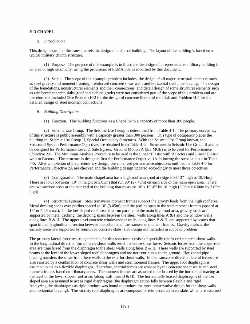
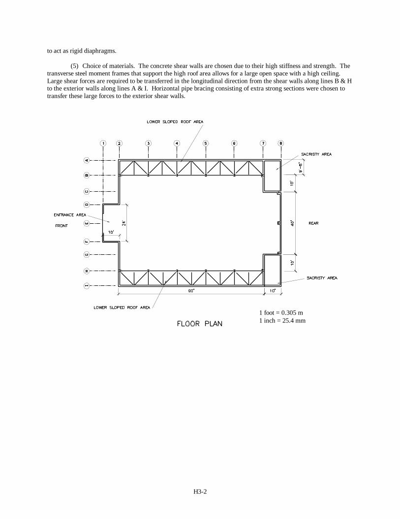
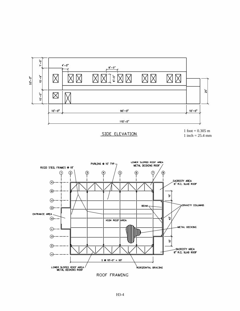
(3) Configuration. The main chapel area has a high roof area (roof at ridge is 33’-3” high or 10.14m).There are low roof areas (10’ in height or 3.05m) that run 90’ (27.45m) on each side of the main open area. Thereare two sacristy areas at the rear end of the building that measure 10’ x 19’-8” by 10’ high (3.05m x 6.00m by 3.05mhigh)
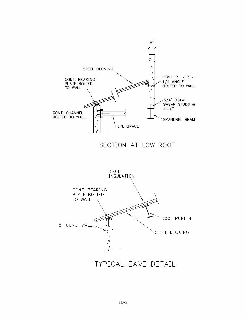
(4) Structural systems. Steel transverse moment frames support the gravity loads from the high roof area.Metal decking spans over purlins spaced at 10’ (3.05m), and the purlins span to the steel moment frames (spaced at18’ or 5.49m o.c.). In the low sloped roof areas that run parallel to the main high roof area, gravity loads aresupported by metal decking, the decking spans between the shear walls along lines A & I and the window wallsalong lines B & H. The upper level concrete window/shear walls along lines B & H are supported by beams thatspan in the longitudinal direction between the columns of the transverse moment frames. Gravity loads at thesacristy areas are supported by reinforced concrete slabs (slab design not included in scope of problem).
The primary lateral force resisting elements for this structure consists of specially reinforced concrete shear walls.In the longitudinal direction the concrete shear walls resist the entire shear force. Seismic forces from the upper roofarea are transferred from the diaphragm to the shear walls along lines B & H. These walls are supported by steelbeams at the level of the lower sloped roof diaphragms and are not continuous to the ground. Horizontal pipebracing transfers the shear from these walls to the exterior shear walls. In the transverse direction lateral forces arealso resisted by a combination of concrete shear walls and steel moment frames. The upper roof diaphragm isassumed to act as a flexible diaphragm. Therefore, inertial forces are resisted by the concrete shear walls and steelmoment frames based on tributary areas. The moment frames are assumed to be braced by the horizontal bracing atthe level of the lower sloped roof areas (along wall lines B & H). The horizontally braced diaphragms of the lowsloped area are assumed to act as rigid diaphragms (the diaphragm action falls between flexible and rigid.Analyzing the diaphragms as rigid produce was found to produce the most conservative design for the shear wallsand horizontal bracing). The sacristy roof diaphragms are composed of reinforced concrete slabs which are assumed
H3-2
to act as rigid diaphragms.
(5) Choice of materials. The concrete shear walls are chosen due to their high stiffness and strength. Thetransverse steel moment frames that support the high roof area allows for a large open space with a high ceiling.Large shear forces are required to be transferred in the longitudinal direction from the shear walls along lines B & Hto the exterior walls along lines A & I. Horizontal pipe bracing consisting of extra strong sections were chosen totransfer these large forces to the exterior shear walls.
1 foot = 0.305 m1 inch = 25.4 mm
H3-3
1 foot = 0.305 m1 inch = 25.4 mm
H3-4
1 foot = 0.305 m1 inch = 25.4 mm
H3-5
H3-6
H3-7
c. Preliminary building design (Following steps in Table 4-5 for Life Safety). The preliminary design of thebuilding follows the steps outlined in Table 4-5 for Performance Objective 1A. The design is then updated to meetthe enhanced performance objectives laid out in Table 4-6 for Performance Objective 2A.
A-1 Determine appropriate Seismic Use Group. The structure falls into Seismic Use Group II.
A-2 Determine Site Seismicity. The site seismicity for this example from the MCE maps is:SS = 1.50g S1 = 0.75g.
A-3 Determine Site Characteristics. The soil for this example site is assumed to correspond to site class D.
A-4 Determine Site Coefficients, Fa and Fv. From Tables 3-2a and 3-2b for the given site seismicity and soilcharacteristics the site coefficients are:Fa = 1.0 Fv = 1.5
A-5 Determine adjusted MCE spectral response accelerations:S F S g gMS a S= = =( . )( . ) .10 15 150 Eq. 3-1S F S g gM v1 1 15 0 75 113= = =( . )( . ) . Eq. 3-2
A-6 Determine design spectral response accelerations:S S g gDS MS= = =2 3 2 3 15 10/ / ( . ) . Eq. 3.3S S g gD M1 12 3 2 3 113 0 75= = =/ / ( . ) . Eq. 3.4For regular structures, 5-stories or less in height, and having a period, T, of 0.5 seconds or less, the designspectral acceleration need not exceed:S F g gDS a≤ = = >15 15 10 150 10. ( . )( . ) . . Eq. 3-5S F g gD v1 0 6 0 6 15 0 9 0 75≤ = = >. ( . )( . ) . . Eq. 3-6
A-7 Select structural design category. From Tables 4-2a and 4-2b for Seismic Use Group II and the designspectral response accelerations:Seismic Design Category = Da Table 4-2aSeismic Design Category = Da Table 4-2bFootnote ‘a’ requires that structures with S1 ≥ 0.75g be assigned to Seismic Design Category E.
A-8 Select structural system. The lateral system consists of a combination of special concrete shear walls andintermediate steel moment frames. In the transverse direction, the structure has concrete shear walls at theends and moment frames in the interior. Longitudinally, concrete shear walls resist the lateral forces.
The upper roof diaphragm consists of metal decking that acts as a flexible diaphragm. The metal deckdiaphragm spans are less than 2:1 in accordance with the limits for diaphragm span and depth set forth inTable 7-24. The lower roof diaphragm in the longitudinal direction consists of horizontal pipe bracing thattransfers the shear from the suspended upper concrete shear walls to the exterior shear walls.
A-9 Select R, Ωo & Cd factors.
Transverse (North-South): Building frame system with special reinforced concrete shear walls:R = 6Ω o = 2.5 Table 7-1Cd = 5
Longitudinal (East-West): Building frame system with special reinforced concrete shear walls: R = 6
Ω o = 2.5 Table 7-1Cd = 5
H3-8
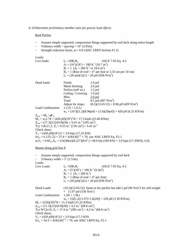
A-10 Determine preliminary member sizes for gravity load effects.
Roof Purlins
− Assume simply supported, compression flange supported by roof deck along entire length− Tributary width = spacing = 10’ (3.05m)− Strength reduction factor, φ = 0.9 (AISC LRFD Section F1.2)
Loads:Live loads: Lr =20R1R2 ASCE 7-95 Eq. 4-2 At = (10’)(18’) = 180 ft.2 (16.7 m2) R1 = 1 (At < 200 ft.2 or 18.6 m2) R2 = 1 (Rise of roof = 4” per foot or 3.33 cm per 10 cm) Lr = (20 psf)(1)(1) = 20 psf (958 N/m2)
Dead loads: Finish 1.0 psf Metal Decking 2.0 psf Purlins (self wt.) 1.5 psf Ceiling / Covering 1.0 psf Misc. 3.0 psf Total: 8.5 psf (407 N/m2) Adjust for slope: (8.5)(12.65/12) = 8.96 plf (429 N/m2)Load Combination: 1.2 D + 1.6 Lr wu = (10’)[(1.2)(8.96psf) + (1.6)(20psf)] = 428 plf (6.25 KN/m)Zreq = Mu / φFy,Mu = wuL2/8 = (428 plf)(18’)2/8 = 17.3 kipft (23.46 KNm)Zreq = (17.3)(12)/(0.9)(36) = 6.41 in.3 (105 cm3)Try C8x11.5, Zx = 9.55 in.3 (156 cm3) > 6.41 in.3
Check shear;Vu = (428 plf)(18’)/2 = 3.9 kips (17.35 KN)h/tw = 6.125/.22 = 27.8 < 418/(36)1/2 = 70, use AISC LRFD Eq. F2-1φvVn = 0.6FywAw = 0.6(36ksi)(0.22”)(8.0”) =38.0 kip (169 KN) > 3.9 kips (17.35KN), O.K.
Beams along grid line 8
− Assume simply supported, compression flange supported by roof deck− Tributary width = 5’ (1.53m)Loads:Live Loads: Lr =20R1R2 ASCE 7-95 Eq. 4-2 At = (5’)(20’) = 100 ft.2 (9.3m2) R1 = 1 (At < 200 ft.2) R2 = 1 (Rise of roof = 4” per foot) Lr = (20 psf)(1)(1) = 20 psf (958 N/m2)
Dead Loads: (10.5)(12.65/12); Same as for purlins but add 2 psf (96 N/m2) for self-weight = 11.07 psf (530 N/m2)Load Combination: 1.2D + 1.6Lr wu = (5)[1.2(11.07)+1.6(20)] = 226 plf (3.30 KN/m)Mu = (226)(20)2/8 = 11.3 kipft (15.32 KNm)Zreq = (11.3)(12)/(0.9)(36) = 4.2 in.3 (68.8 cm3)Try W12x14, Zx = 17.4 in.3 (285 cm3) > 4.2 in.3 (68.8 cm3)Check shear;Vu = (428 plf)(18’)/2 = 3.9 kips (17.3 KN)h/tw = 54.3 < 418/(36)1/2 = 70, use AISC LRFD Eq. F2-1
H3-10
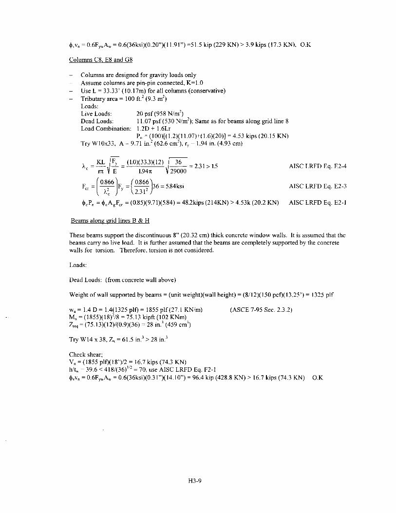
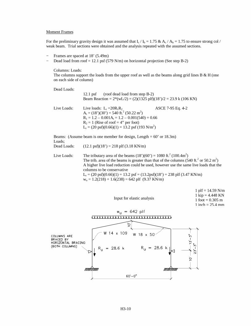
Moment Frames
For the preliminary gravity design it was assumed that Ic / Ib = 1.75 & Ac / Ab = 1.75 to ensure strong col /weak beam. Trial sections were obtained and the analysis repeated with the assumed sections.
− Frames are spaced at 18’ (5.49m)− Dead load from roof = 12.1 psf (579 N/m) on horizontal projection (See step B-2)
Columns: Loads:The columns support the loads from the upper roof as well as the beams along grid lines B & H (oneon each side of column)
Dead Loads: 12.1 psf (roof dead load from step B-2) Beam Reaction = 2*(wL/2) = (2)(1325 plf)(18’)/2 = 23.9 k (106 KN)
Live Loads: Live loads: Lr =20R1R2 ASCE 7-95 Eq. 4-2 At = (18’)(30’) = 540 ft.2 (50.22 m2) R1 = 1.2 – 0.001At = 1.2 – 0.001(540) = 0.66 R2 = 1 (Rise of roof = 4” per foot) Lr = (20 psf)(0.66)(1) = 13.2 psf (193 N/m2)
Beams: (Assume beam is one member for design, Length = 60’ or 18.3m)Loads;Dead Loads: (12.1 psf)(18’) = 218 plf (3.18 KN/m)
Live Loads: The tributary area of the beams (18’)(60’) = 1080 ft.2 (100.4m2) The trib. area of the beams is greater than that of the columns (540 ft.2 or 50.2 m2) A higher live load reduction could be used, however use the same live loads that the columns to be conservative Lr = (20 psf)(0.66)(1) = 13.2 psf = (13.2psf)(18’) = 238 plf (3.47 KN/m) wu = 1.2(218) + 1.6(238) = 642 plf (9.37 KN/m)
Input for elastic analysis
1 plf = 14.59 N/m1 kip = 4.448 KN1 foot = 0.305 m1 inch = 25.4 mm
H3-13
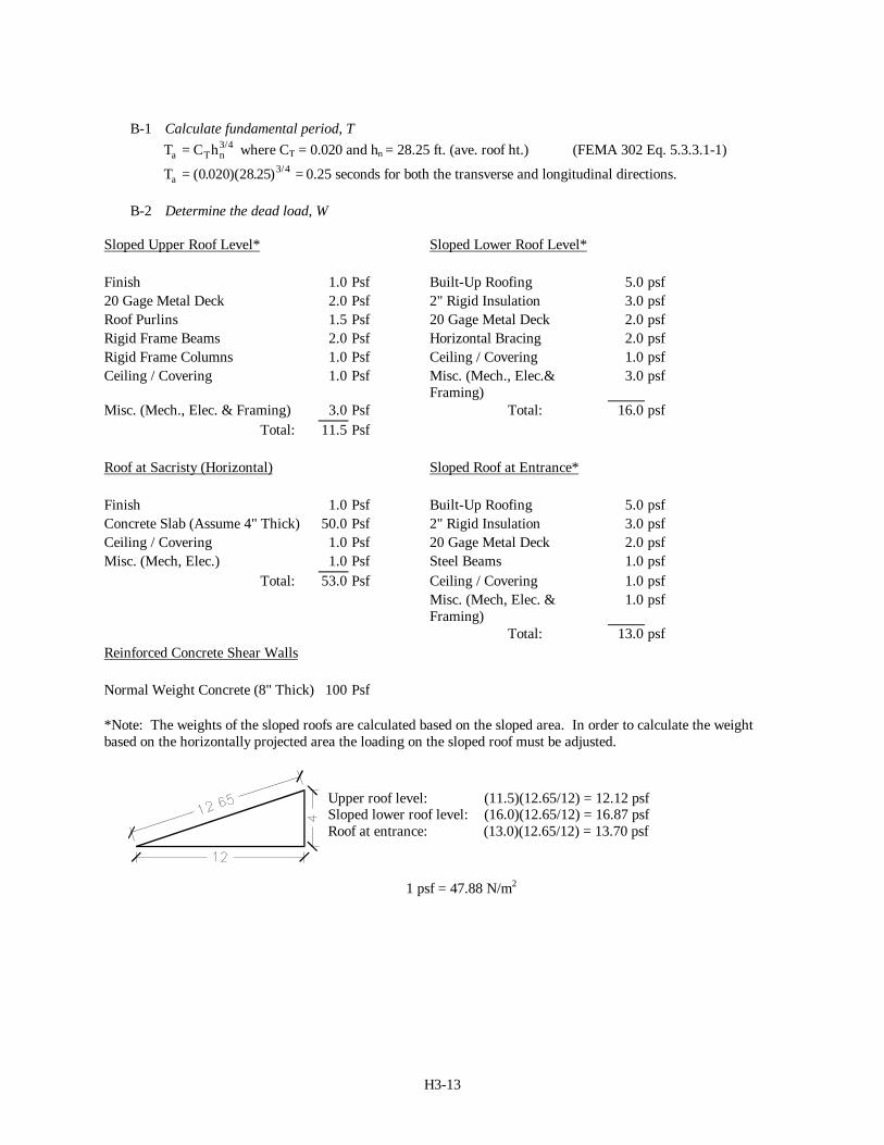
B-1 Calculate fundamental period, TT C ha T n= 3 4/ where CT = 0.020 and hn = 28.25 ft. (ave. roof ht.) (FEMA 302 Eq. 5.3.3.1-1)
Ta = =( . )( . ) /0 020 28 25 3 4 0.25 seconds for both the transverse and longitudinal directions.
B-2 Determine the dead load, W
Sloped Upper Roof Level* Sloped Lower Roof Level*
Finish 1.0 Psf Built-Up Roofing 5.0 psf20 Gage Metal Deck 2.0 Psf 2" Rigid Insulation 3.0 psfRoof Purlins 1.5 Psf 20 Gage Metal Deck 2.0 psfRigid Frame Beams 2.0 Psf Horizontal Bracing 2.0 psfRigid Frame Columns 1.0 Psf Ceiling / Covering 1.0 psfCeiling / Covering 1.0 Psf Misc. (Mech., Elec.&
Framing)3.0 psf
Misc. (Mech., Elec. & Framing) 3.0 Psf Total: 16.0 psfTotal: 11.5 Psf
Roof at Sacristy (Horizontal) Sloped Roof at Entrance*
Finish 1.0 Psf Built-Up Roofing 5.0 psfConcrete Slab (Assume 4" Thick) 50.0 Psf 2" Rigid Insulation 3.0 psfCeiling / Covering 1.0 Psf 20 Gage Metal Deck 2.0 psfMisc. (Mech, Elec.) 1.0 Psf Steel Beams 1.0 psf
Total: 53.0 Psf Ceiling / Covering 1.0 psfMisc. (Mech, Elec. &Framing)
1.0 psf
Total: 13.0 psfReinforced Concrete Shear Walls
Normal Weight Concrete (8" Thick) 100 Psf
*Note: The weights of the sloped roofs are calculated based on the sloped area. In order to calculate the weightbased on the horizontally projected area the loading on the sloped roof must be adjusted.
Upper roof level: (11.5)(12.65/12) = 12.12 psfSloped lower roof level: (16.0)(12.65/12) = 16.87 psfRoof at entrance: (13.0)(12.65/12) = 13.70 psf
1 psf = 47.88 N/m2
H3-14
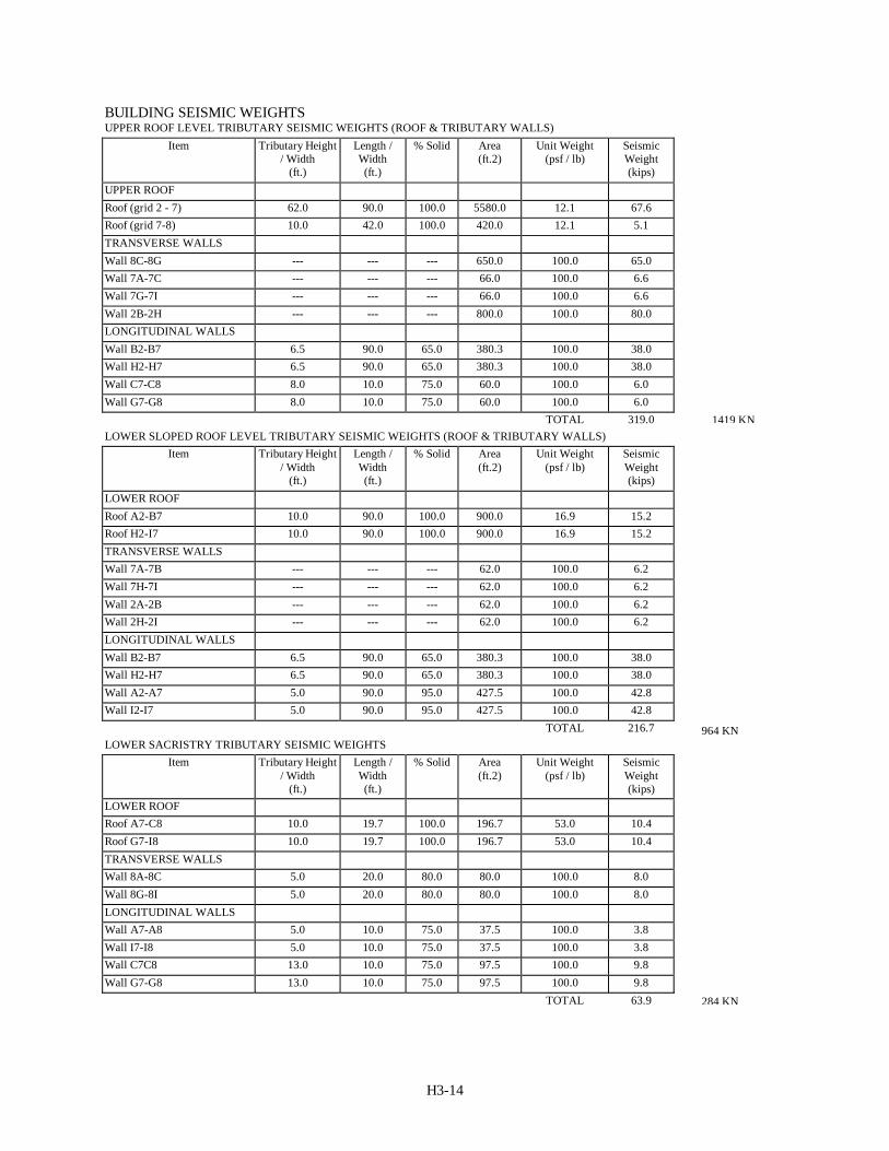
BUILDING SEISMIC WEIGHTSUPPER ROOF LEVEL TRIBUTARY SEISMIC WEIGHTS (ROOF & TRIBUTARY WALLS)
Item Tributary Height/ Width
(ft.)
Length /Width(ft.)
% Solid Area(ft.2)
Unit Weight(psf / lb)
SeismicWeight(kips)
UPPER ROOFRoof (grid 2 - 7) 62.0 90.0 100.0 5580.0 12.1 67.6Roof (grid 7-8) 10.0 42.0 100.0 420.0 12.1 5.1TRANSVERSE WALLSWall 8C-8G --- --- --- 650.0 100.0 65.0Wall 7A-7C --- --- --- 66.0 100.0 6.6Wall 7G-7I --- --- --- 66.0 100.0 6.6Wall 2B-2H --- --- --- 800.0 100.0 80.0LONGITUDINAL WALLSWall B2-B7 6.5 90.0 65.0 380.3 100.0 38.0Wall H2-H7 6.5 90.0 65.0 380.3 100.0 38.0Wall C7-C8 8.0 10.0 75.0 60.0 100.0 6.0Wall G7-G8 8.0 10.0 75.0 60.0 100.0 6.0
TOTAL 319.0LOWER SLOPED ROOF LEVEL TRIBUTARY SEISMIC WEIGHTS (ROOF & TRIBUTARY WALLS)
Item Tributary Height/ Width
(ft.)
Length /Width(ft.)
% Solid Area(ft.2)
Unit Weight(psf / lb)
SeismicWeight(kips)
LOWER ROOFRoof A2-B7 10.0 90.0 100.0 900.0 16.9 15.2Roof H2-I7 10.0 90.0 100.0 900.0 16.9 15.2TRANSVERSE WALLSWall 7A-7B --- --- --- 62.0 100.0 6.2Wall 7H-7I --- --- --- 62.0 100.0 6.2Wall 2A-2B --- --- --- 62.0 100.0 6.2Wall 2H-2I --- --- --- 62.0 100.0 6.2LONGITUDINAL WALLSWall B2-B7 6.5 90.0 65.0 380.3 100.0 38.0Wall H2-H7 6.5 90.0 65.0 380.3 100.0 38.0Wall A2-A7 5.0 90.0 95.0 427.5 100.0 42.8Wall I2-I7 5.0 90.0 95.0 427.5 100.0 42.8
TOTAL 216.7LOWER SACRISTRY TRIBUTARY SEISMIC WEIGHTS
Item Tributary Height/ Width
(ft.)
Length /Width(ft.)
% Solid Area(ft.2)
Unit Weight(psf / lb)
SeismicWeight(kips)
LOWER ROOFRoof A7-C8 10.0 19.7 100.0 196.7 53.0 10.4Roof G7-I8 10.0 19.7 100.0 196.7 53.0 10.4TRANSVERSE WALLSWall 8A-8C 5.0 20.0 80.0 80.0 100.0 8.0Wall 8G-8I 5.0 20.0 80.0 80.0 100.0 8.0LONGITUDINAL WALLSWall A7-A8 5.0 10.0 75.0 37.5 100.0 3.8Wall I7-I8 5.0 10.0 75.0 37.5 100.0 3.8Wall C7C8 13.0 10.0 75.0 97.5 100.0 9.8Wall G7-G8 13.0 10.0 75.0 97.5 100.0 9.8
TOTAL 63.9
1419 KN
964 KN
284 KN
H3-15
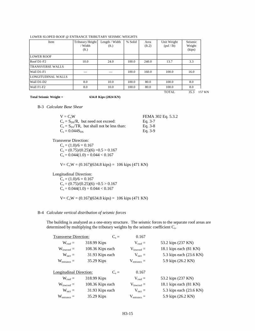
LOWER SLOPED ROOF @ ENTRANCE TRIBUTARY SEISMIC WEIGHTSItem Tributary Height
/ Width(ft.)
Length / Width(ft.)
% Solid Area(ft.2)
Unit Weight(psf / lb)
SeismicWeight(kips)
LOWER ROOFRoof D1-F2 10.0 24.0 100.0 240.0 13.7 3.3TRANSVERSE WALLSWall D1-F1 --- --- 100.0 160.0 100.0 16.0LONGITUDINAL WALLSWall D1-D2 8.0 10.0 100.0 80.0 100.0 8.0Wall F1-F2 8.0 10.0 100.0 80.0 100.0 8.0
TOTAL 35.3Total Seismic Weight = 634.8 Kips (2824 KN)
B-3 Calculate Base Shear
V = CsW FEMA 302 Eq. 5.3.2Cs = SDS/R, but need not exceed: Eq. 3-7Cs = SD1/TR, but shall not be less than: Eq. 3-8Cs = 0.044SDS Eq. 3-9
Transverse Direction:Cs = (1.0)/6 = 0.167Cs = (0.75)/(0.25)(6) =0.5 > 0.167Cs = 0.044(1.0) = 0.044 < 0.167
V= CsW = (0.167)(634.8 kips) = 106 kips (471 KN)
Longitudinal Direction:Cs = (1.0)/6 = 0.167Cs = (0.75)/(0.25)(6) =0.5 > 0.167Cs = 0.044(1.0) = 0.044 < 0.167
V= CsW = (0.167)(634.8 kips) = 106 kips (471 KN)
B-4 Calculate vertical distribution of seismic forces
The building is analyzed as a one-story structure. The seismic forces to the separate roof areas aredetermined by multiplying the tributary weights by the seismic coefficient Cs.
Transverse Direction: Cs = 0.167Wroof = 318.99 Kips Vroof = 53.2 kips (237 KN)
Wlowroof = 108.36 Kips each Vlowroof = 18.1 kips each (81 KN)Wsacr = 31.93 Kips each Vsacr = 5.3 kips each (23.6 KN)
Wentrance = 35.29 Kips Ventrance = 5.9 kips (26.2 KN)
Longitudinal Direction: Cs = 0.167Wroof = 318.99 Kips Vroof = 53.2 kips (237 KN)
Wlowroof = 108.36 Kips each Vlowroof = 18.1 kips each (81 KN)Wsacr = 31.93 Kips each Vsacr = 5.3 kips each (23.6 KN)
Wentrance = 35.29 Kips Ventrance = 5.9 kips (26.2 KN)
157 KN
H3-16
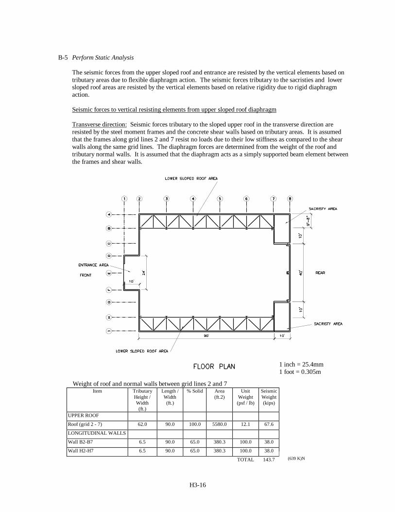
B-5 Perform Static Analysis
The seismic forces from the upper sloped roof and entrance are resisted by the vertical elements based ontributary areas due to flexible diaphragm action. The seismic forces tributary to the sacristies and lowersloped roof areas are resisted by the vertical elements based on relative rigidity due to rigid diaphragmaction.
Seismic forces to vertical resisting elements from upper sloped roof diaphragm
Transverse direction: Seismic forces tributary to the sloped upper roof in the transverse direction areresisted by the steel moment frames and the concrete shear walls based on tributary areas. It is assumedthat the frames along grid lines 2 and 7 resist no loads due to their low stiffness as compared to the shearwalls along the same grid lines. The diaphragm forces are determined from the weight of the roof andtributary normal walls. It is assumed that the diaphragm acts as a simply supported beam element betweenthe frames and shear walls.
Weight of roof and normal walls between grid lines 2 and 7Item Tributary
Height /Width(ft.)
Length /Width(ft.)
% Solid Area(ft.2)
UnitWeight(psf / lb)
SeismicWeight(kips)
UPPER ROOF
Roof (grid 2 - 7) 62.0 90.0 100.0 5580.0 12.1 67.6
LONGITUDINAL WALLS
Wall B2-B7 6.5 90.0 65.0 380.3 100.0 38.0
Wall H2-H7 6.5 90.0 65.0 380.3 100.0 38.0
TOTAL 143.7
1 inch = 25.4mm1 foot = 0.305m
(639 K)N
H3-17
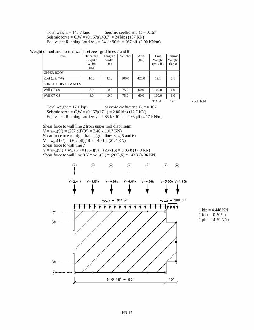
Total weight = 143.7 kips Seismic coefficient, Cs = 0.167Seismic force = CsW = (0.167)(143.7) = 24 kips (107 KN)Equivalent Running Load w2-7 = 24 k / 90 ft. = 267 plf (3.90 KN/m)
Weight of roof and normal walls between grid lines 7 and 8Item Tributary
Height /Width(ft.)
Length /Width(ft.)
% Solid Area(ft.2)
UnitWeight(psf / lb)
SeismicWeight(kips)
UPPER ROOF
Roof (grid 7-8) 10.0 42.0 100.0 420.0 12.1 5.1
LONGITUDINAL WALLS
Wall C7-C8 8.0 10.0 75.0 60.0 100.0 6.0
Wall G7-G8 8.0 10.0 75.0 60.0 100.0 6.0
TOTAL 17.1
Total weight = 17.1 kips Seismic coefficient, Cs = 0.167Seismic force = CsW = (0.167)(17.1) = 2.86 kips (12.7 KN)Equivalent Running Load w7-8 = 2.86 k / 10 ft. = 286 plf (4.17 KN/m)
Shear force to wall line 2 from upper roof diaphragm:V = w2-7(9’) = (267 plf)(9’) = 2.40 k (10.7 KN)Shear force to each rigid frame (grid lines 3, 4, 5 and 6)V = w2-7(18’) = (267 plf)(18’) = 4.81 k (21.4 KN)Shear force to wall line 7V = w2-7(9’) + w7-8(5’) = (267)(9) + (286)(5) = 3.83 k (17.0 KN)Shear force to wall line 8 V = w7-8(5’) = (286)(5) =1.43 k (6.36 KN)
76.1 KN
1 kip = 4.448 KN1 foot = 0.305m1 plf = 14.59 N/m
H3-18
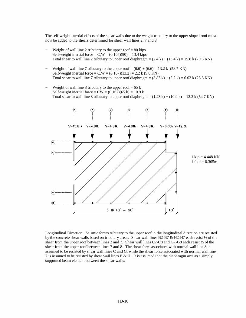
The self-weight inertial effects of the shear walls due to the weight tributary to the upper sloped roof mustnow be added to the shears determined for shear wall lines 2, 7 and 8.
− Weight of wall line 2 tributary to the upper roof = 80 kipsSelf-weight inertial force = CsW = (0.167)(80) = 13.4 kipsTotal shear to wall line 2 tributary to upper roof diaphragm = (2.4 k) + (13.4 k) = 15.8 k (70.3 KN)
− Weight of wall line 7 tributary to the upper roof = (6.6) + (6.6) = 13.2 k (58.7 KN)Self-weight inertial force = CsW = (0.167)(13.2) = 2.2 k (9.8 KN)Total shear to wall line 7 tributary to upper roof diaphragm = (3.83 k) + (2.2 k) = 6.03 k (26.8 KN)
− Weight of wall line 8 tributary to the upper roof = 65 kSelf-weight inertial force = CW = (0.167)(65 k) = 10.9 kTotal shear to wall line 8 tributary to upper roof diaphragm = (1.43 k) + (10.9 k) = 12.3 k (54.7 KN)
Longitudinal Direction: Seismic forces tributary to the upper roof in the longitudinal direction are resistedby the concrete shear walls based on tributary areas. Shear wall lines B2-B7 & H2-H7 each resist ½ of theshear from the upper roof between lines 2 and 7. Shear wall lines C7-C8 and G7-G8 each resist ½ of theshear from the upper roof between lines 7 and 8. The shear force associated with normal wall line 8 isassumed to be resisted by shear wall lines C and G, while the shear force associated with normal wall line7 is assumed to be resisted by shear wall lines B & H. It is assumed that the diaphragm acts as a simplysupported beam element between the shear walls.
1 kip = 4.448 KN1 foot = 0.305m
H3-19
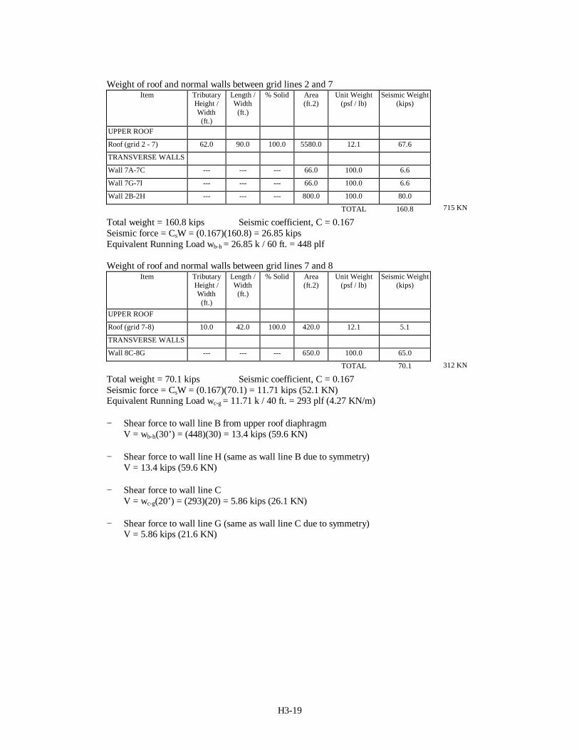
Weight of roof and normal walls between grid lines 2 and 7Item Tributary
Height /Width(ft.)
Length /Width(ft.)
% Solid Area(ft.2)
Unit Weight(psf / lb)
Seismic Weight(kips)
UPPER ROOF
Roof (grid 2 - 7) 62.0 90.0 100.0 5580.0 12.1 67.6
TRANSVERSE WALLS
Wall 7A-7C --- --- --- 66.0 100.0 6.6
Wall 7G-7I --- --- --- 66.0 100.0 6.6
Wall 2B-2H --- --- --- 800.0 100.0 80.0
TOTAL 160.8
Total weight = 160.8 kips Seismic coefficient, C = 0.167Seismic force = CsW = (0.167)(160.8) = 26.85 kipsEquivalent Running Load wb-h = 26.85 k / 60 ft. = 448 plf
Weight of roof and normal walls between grid lines 7 and 8Item Tributary
Height /Width(ft.)
Length /Width(ft.)
% Solid Area(ft.2)
Unit Weight(psf / lb)
Seismic Weight(kips)
UPPER ROOF
Roof (grid 7-8) 10.0 42.0 100.0 420.0 12.1 5.1
TRANSVERSE WALLS
Wall 8C-8G --- --- --- 650.0 100.0 65.0
TOTAL 70.1
Total weight = 70.1 kips Seismic coefficient, C = 0.167Seismic force = CsW = (0.167)(70.1) = 11.71 kips (52.1 KN)Equivalent Running Load wc-g = 11.71 k / 40 ft. = 293 plf (4.27 KN/m)
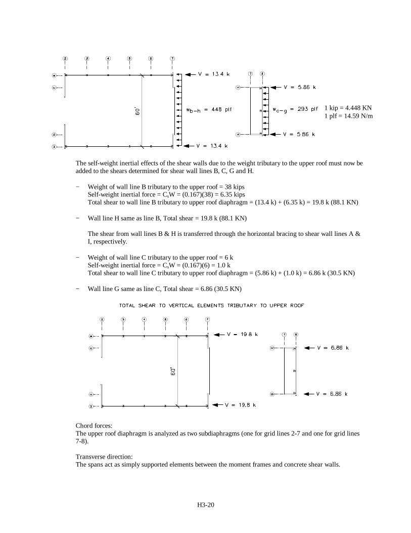
− Shear force to wall line B from upper roof diaphragmV = wb-h(30’) = (448)(30) = 13.4 kips (59.6 KN)
− Shear force to wall line H (same as wall line B due to symmetry)V = 13.4 kips (59.6 KN)
− Shear force to wall line CV = wc-g(20’) = (293)(20) = 5.86 kips (26.1 KN)
− Shear force to wall line G (same as wall line C due to symmetry)V = 5.86 kips (21.6 KN)
715 KN
312 KN
H3-20
The self-weight inertial effects of the shear walls due to the weight tributary to the upper roof must now beadded to the shears determined for shear wall lines B, C, G and H.
− Weight of wall line B tributary to the upper roof = 38 kipsSelf-weight inertial force = CsW = (0.167)(38) = 6.35 kipsTotal shear to wall line B tributary to upper roof diaphragm = (13.4 k) + (6.35 k) = 19.8 k (88.1 KN)
− Wall line H same as line B, Total shear = 19.8 k (88.1 KN)
The shear from wall lines B & H is transferred through the horizontal bracing to shear wall lines A &I, respectively.
− Weight of wall line C tributary to the upper roof = 6 kSelf-weight inertial force = CsW = (0.167)(6) = 1.0 kTotal shear to wall line C tributary to upper roof diaphragm = (5.86 k) + (1.0 k) = 6.86 k (30.5 KN)
− Wall line G same as line C, Total shear = 6.86 (30.5 KN)
Chord forces:The upper roof diaphragm is analyzed as two subdiaphragms (one for grid lines 2-7 and one for grid lines7-8).
Transverse direction:The spans act as simply supported elements between the moment frames and concrete shear walls.
1 kip = 4.448 KN1 plf = 14.59 N/m
H3-21
w2-7 = 267 plf (3.90 KN/m)M = wL2/8 = (0.267)(18 ft)2 / 8 = 10.8 kipft (14.64 KNm)T = M / d = (10.8 / 60 ft) = 0.18 kips (801N)
w7-8 = 286 plf (4.17 KN/m)M = wL2/8 = (0.286)(10 ft)2 / 8 = 3.58 kipft (4.85 KNm)T = M / d = (3.58 / 40 ft) = 0.09 kips (0.40 KN)
Longitudinal direction:The spans act as simply supported elements between the concrete shear walls.
w2-7 = 448 plf (6.54 KN/m)M = wL2/8 = (0.448)(60 ft)2 / 8 = 202 kipft (274 KNm)T = M / d = (202 / 90 ft) = 2.24 kips (9.96 KN)
w7-8 = 293 plf (4.27 KN/m)M = wL2/8 = (0.293)(40 ft)2 / 8 = 58.6 kipft (79.5 KNm)T = M / d = ( 58.6 / 10 ft) = 5.86 kips (26.1 KN)
Seismic forces to vertical resisting elements from lower sloped roof diaphragm
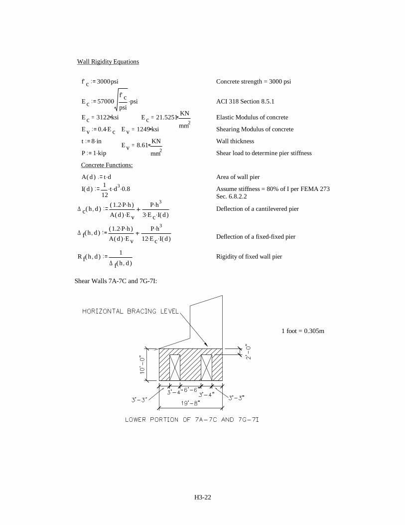
Transverse direction: The horizontally braced diaphragms are assumed to act as rigid diaphragmsspanning between the steel rigid frames and the end shear walls along lines 2 and 7. Due to the lowstiffness of the moment frames as compared to that of the end concrete shear walls, it is assumed that allof the shear is distributed to the end walls in relation to their relative rigidities.
Determine relative rigidities of concrete shear walls at ends of low sloped roof area:
H3-22
Wall Rigidity Equations
f' c 3000psi. Concrete strength = 3000 psi
E c 57000f' cpsi
. psi. ACI 318 Section 8.5.1
E c 3122 ksi= E c 21.5251 KN
mm2= Elastic Modulus of concrete
E v 0.4 E c. E v 1249 ksi= Shearing Modulus of concrete
t 8 in. Wall thicknessE v 8.61 KN
mm2=
P 1 kip. Shear load to determine pier stiffness
Concrete Functions:
A d( ) t d. Area of wall pier
I d( ) 112
t. d3. 0.8. Assume stiffness = 80% of I per FEMA 273 Sec. 6.8.2.2
∆ c h d,( ) 1.2 P. h.( )A d( ) E v.
P h3.3 E c. I d( ). Deflection of a cantilevered pier
∆ f h d,( ) 1.2 P. h.( )A d( ) E v.
P h3.12 E c. I d( ). Deflection of a fixed-fixed pier
R f h d,( ) 1
∆ f h d,( )Rigidity of fixed wall pier
Shear Walls 7A-7C and 7G-7I:
1 foot = 0.305m
H3-23
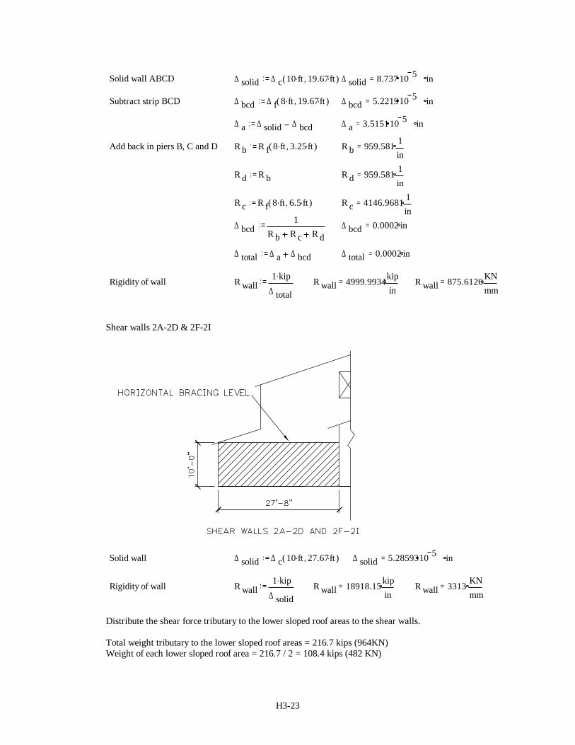
Solid wall ABCD ∆ solid ∆ c 10 ft. 19.67ft.,( ) ∆ solid 8.737 10 5 in=
Subtract strip BCD ∆ bcd ∆ f 8 ft. 19.67ft.,( ) ∆ bcd 5.221910 5 in=
∆ a ∆ solid ∆ bcd ∆ a 3.515110 5 in=
Add back in piers B, C and D R b R f 8 ft. 3.25 ft.,( ) R b 959.581 1in
=
R d R b R d 959.581 1in
=
R c R f 8 ft. 6.5 ft.,( ) R c 4146.9681 1in
=
∆ bcd1
R b R c R d∆ bcd 0.0002 in=
∆ total ∆ a ∆ bcd ∆ total 0.0002 in=
Rigidity of wall R wall1 kip.
∆ totalR wall 4999.9934kip
in= R wall 875.6126 KN
mm=
Shear walls 2A-2D & 2F-2I
Solid wall ∆ solid ∆ c 10 ft. 27.67ft.,( ) ∆ solid 5.2859310 5 in=
Rigidity of wall R wall1 kip.
∆ solidR wall 18918.15 kip
in= R wall 3313 KN
mm=
Distribute the shear force tributary to the lower sloped roof areas to the shear walls.
Total weight tributary to the lower sloped roof areas = 216.7 kips (964KN)Weight of each lower sloped roof area = 216.7 / 2 = 108.4 kips (482 KN)
H3-24
Shear force tributary to each lower sloped roof area = CsW = 0.167(108.4 kips) = 18.1 kips (80.5 KN)
R2A-2D = 18918 kips / in R7A-7C = 5000 kips / in V VR
Relement
element= ∑V2A-2D = 18.1(18918) / (18918+5000) = 14.3 kips (63.6KN)V7A-7C = 18.1(5000)/(18918+5000) = 3.78 kips (16.8 KN)
Due to symmetry, V2F-2I = V2A-2D = 14.3 kips (63.6KN) V7G-7I= V7A-7C = 3.78 kips (16.8 KN)
The horizontal bracing is assumed to act as a rigid support to the transverse moment frames. It is furtherassumed that the end shear walls (along grid lines 2 and 7) are infinitely rigid (relative to the frames).Therefore, the horizontally braced diaphragms of the low sloped roof will transmit the shear forces fromthe moment frames (shear forces tributary to the high roof) into the end shear walls.
Shear in moment frames from upper roof diaphragm = 4 (4.81 k) = 19.24 k (41.4 KN)
There are two low sloped roof areas (2A-B7 & H2-I7); assume each resists ½ of this shear force.
Shear to each low sloped roof area = ½(19.24k) = 9.62 k (42.8KN)
Distribute shear to walls based on rigidity;
V2A-2D = 9.62(18918) / (18918+5000) = 7.61 kips (33.8 KN)V7A-7C = 9.62(5000)/(18918+5000) = 2.01 kips (8.94 KN)
Due to symmetry, V2F-2I = V2A-2D = 7.61 kips (33.8 KN) V7G-7I= V7A-7C = 2.01 kips (8.94 KN)
Total Shear to walls from lower roof diaphragms;V2A-2D = 14.3 k + 7.61 k = 21.91 k (97.5 KN) V7A-7C = 3.78 k + 2.01 k = 5.79 k (25.8 KN)Due to symmetry, V2F-2I = V2A-2D = 21.91 kips (95.7 KN) V7G-7I = V7A-7C = 5.79 kips (25.8 KN)
Longitudinal direction: The shear walls along grid lines A and I resist all of the shear tributary to the lowsloped roofs.
Diaphragm force:
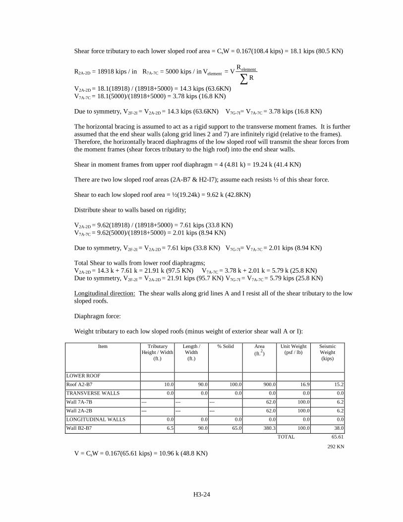
Weight tributary to each low sloped roofs (minus weight of exterior shear wall A or I):
Item TributaryHeight / Width
(ft.)
Length /Width(ft.)
% Solid Area(ft.2)
Unit Weight(psf / lb)
SeismicWeight(kips)
LOWER ROOF
Roof A2-B7 10.0 90.0 100.0 900.0 16.9 15.2
TRANSVERSE WALLS 0.0 0.0 0.0 0.0 0.0 0.0
Wall 7A-7B --- --- --- 62.0 100.0 6.2
Wall 2A-2B --- --- --- 62.0 100.0 6.2
LONGITUDINAL WALLS 0.0 0.0 0.0 0.0 0.0 0.0
Wall B2-B7 6.5 90.0 65.0 380.3 100.0 38.0
TOTAL 65.61
V = CsW = 0.167(65.61 kips) = 10.96 k (48.8 KN)292 KN
H3-25
This shear force must be transferred to the shear walls (A2-A7 & I2-I7) through the horizontal bracing.The bracing also transfers the shear force from wall lines B & H (tributary to the upper roof diaphragm).
Total shear force transferred through horizontal bracing = 19.8 k + 10.96 kips = 30.8 kips (137 KN)
Total shear to walls A2-A7 and I2-I7 = Horizontal bracing shear + shear due to self-weight:
Weight of wall A2-A7 = 42.75 kipsShear due to self-weight = CsW = (0.167)(42.75k) = 7.14 k (318 KN)
Total shear to walls A2-A7 & I2-I7 trib. to high and low sloped roofs = 30.8 k + 7.14 k = 37.9 k (169 KN)
Chord forces:The low sloped roof diaphragm areas are conservatively assumed to span 90 feet (27.45 m) between shearwall lines 2 and 7 for transverse seismic forces. An equivalent running load, w, is found by dividing thetotal shear to the diaphragm by the span. The shear is made up of forces tributary to the low sloped roofareas and the reactions at the moment frames.
Shear force tributary to the low sloped roof areas = 18.1 kips (80.5KN)Shear force to each diaphragm from moment frame reactions = 4(4.81 k) / 2 = 9.62 kips (42.8KN)Total shear force = 18.1 k + 9.62 k = 27.7 kips (123 KN)Equivalent running load, w = V / L = 27.7 / 90’ = 308 plf (4.49 KN/m)Moment = wL2 / 8 = (.308)(90)2 / 8 = 312 kft (423 KNm)T = M / d = 312 / 9.67’ = 32.3 kips (143 KN)
Chord forces for longitudinal seismic forces are negligible by inspection.
Collector forces:The beams along grid lines B & H must collect the shear forces from the upper concrete shear / windowwalls and distribute them to the horizontal bracing of the low sloped roof area. The beams collect theshear force from the upper roof area and the shear force associated with wall lines B & H tributary to thelow sloped roof areas.
Shear force from wall line B tributary to the upper roof diaphragm = 19.8 kips ( 88.1 KN)Weight of wall line B tributary to the low sloped roof area = 15.2 kShear force from wall line B tributary to the low sloped roof area = CsW = (0.167)(15.2k) = 2.54k(11.3KN)Total shear force collected by beams along grid lines B & H = 19.8 + 2.54 = 22.34 kips (99.4 KN)Unit collector shear force, v = V / L = 22.34 kips / 90’ = 248 plf (3.62 KN/m)Collector force = v*Lcollector = (248 plf)(18’) = 4.46 kips (19.8 KN)
Seismic forces to vertical resisting elements from entrance area diaphragm
The concrete shear walls resist seismic shear forces tributary to the entrance area according to theirtributary areas.
H3-26
Transverse direction:
LOWER SLOPED ROOF @ ENTRANCE TRIBUTARY SEISMIC WEIGHTS (ROOF & NORMAL WALLS)
Item TributaryHeight / Width
(ft.)
Length /Width(ft.)
% Solid Area(ft.2)
Unit Weight(psf / lb)
Seismic Weight(kips)
LOWER ROOF
Roof D1-F2 10.0 24.0 100.0 240.0 13.7 3.3
LONGITUDINAL WALLS
Wall D1-D2 8.0 10.0 100.0 80.0 100.0 8.0
Wall F1-F2 8.0 10.0 100.0 80.0 100.0 8.0
TOTAL 19.3
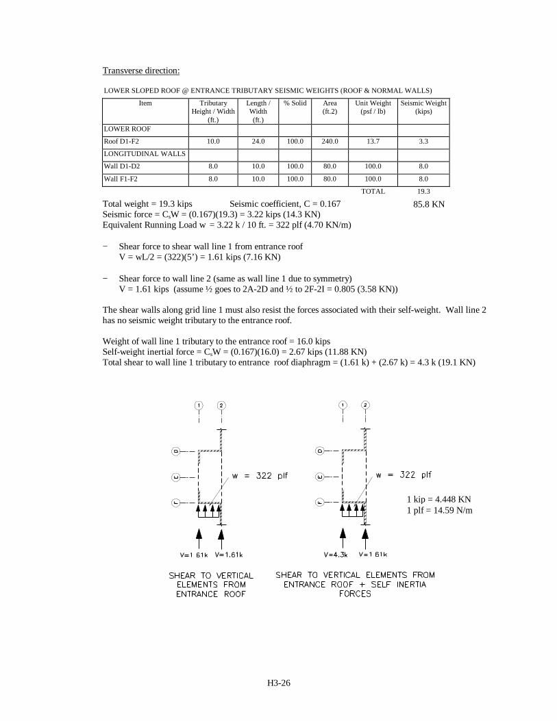
Total weight = 19.3 kips Seismic coefficient, C = 0.167Seismic force = CsW = (0.167)(19.3) = 3.22 kips (14.3 KN)Equivalent Running Load w = 3.22 k / 10 ft. = 322 plf (4.70 KN/m)
− Shear force to shear wall line 1 from entrance roofV = wL/2 = (322)(5’) = 1.61 kips (7.16 KN)
− Shear force to wall line 2 (same as wall line 1 due to symmetry)V = 1.61 kips (assume ½ goes to 2A-2D and ½ to 2F-2I = 0.805 (3.58 KN))
The shear walls along grid line 1 must also resist the forces associated with their self-weight. Wall line 2has no seismic weight tributary to the entrance roof.
Weight of wall line 1 tributary to the entrance roof = 16.0 kipsSelf-weight inertial force = CsW = (0.167)(16.0) = 2.67 kips (11.88 KN)Total shear to wall line 1 tributary to entrance roof diaphragm = (1.61 k) + (2.67 k) = 4.3 k (19.1 KN)
85.8 KN
1 kip = 4.448 KN1 plf = 14.59 N/m
H3-27
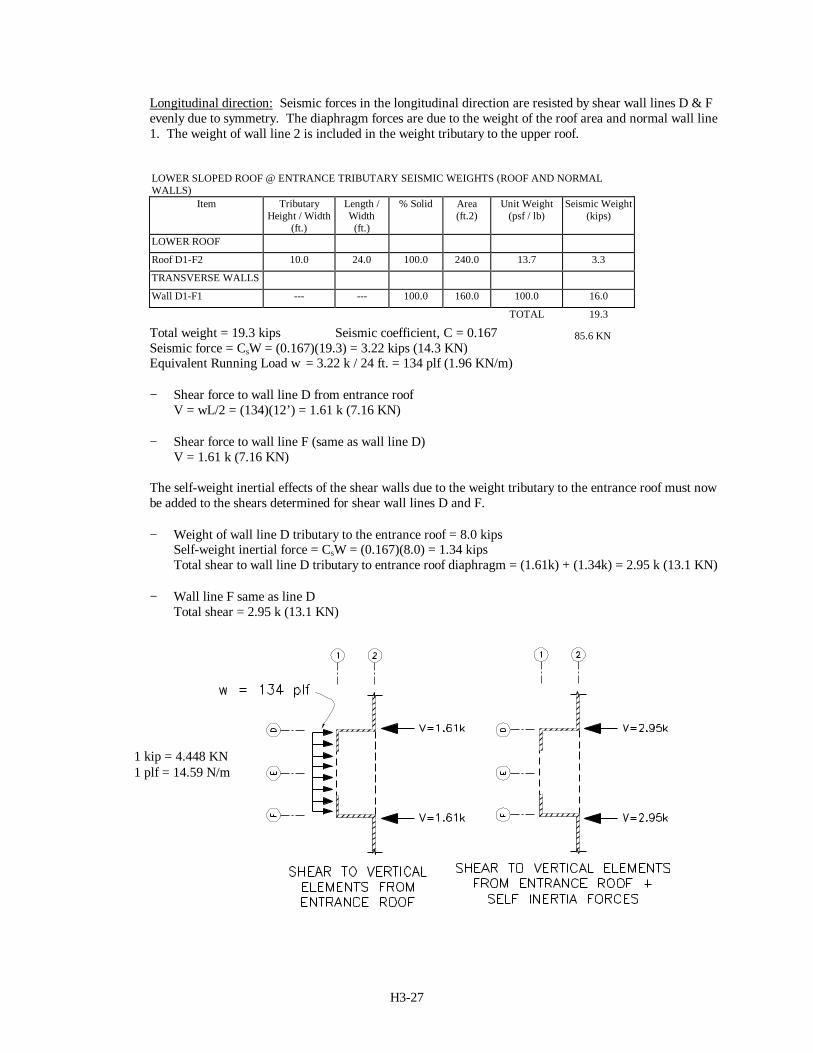
Longitudinal direction: Seismic forces in the longitudinal direction are resisted by shear wall lines D & Fevenly due to symmetry. The diaphragm forces are due to the weight of the roof area and normal wall line1. The weight of wall line 2 is included in the weight tributary to the upper roof.
LOWER SLOPED ROOF @ ENTRANCE TRIBUTARY SEISMIC WEIGHTS (ROOF AND NORMALWALLS)
Item TributaryHeight / Width
(ft.)
Length /Width(ft.)
% Solid Area(ft.2)
Unit Weight(psf / lb)
Seismic Weight(kips)
LOWER ROOF
Roof D1-F2 10.0 24.0 100.0 240.0 13.7 3.3
TRANSVERSE WALLS
Wall D1-F1 --- --- 100.0 160.0 100.0 16.0
TOTAL 19.3
Total weight = 19.3 kips Seismic coefficient, C = 0.167Seismic force = CsW = (0.167)(19.3) = 3.22 kips (14.3 KN)Equivalent Running Load w = 3.22 k / 24 ft. = 134 plf (1.96 KN/m)
− Shear force to wall line D from entrance roofV = wL/2 = (134)(12’) = 1.61 k (7.16 KN)
− Shear force to wall line F (same as wall line D)V = 1.61 k (7.16 KN)
The self-weight inertial effects of the shear walls due to the weight tributary to the entrance roof must nowbe added to the shears determined for shear wall lines D and F.
− Weight of wall line D tributary to the entrance roof = 8.0 kipsSelf-weight inertial force = CsW = (0.167)(8.0) = 1.34 kipsTotal shear to wall line D tributary to entrance roof diaphragm = (1.61k) + (1.34k) = 2.95 k (13.1 KN)
− Wall line F same as line DTotal shear = 2.95 k (13.1 KN)
85.6 KN
1 kip = 4.448 KN1 plf = 14.59 N/m
H3-28
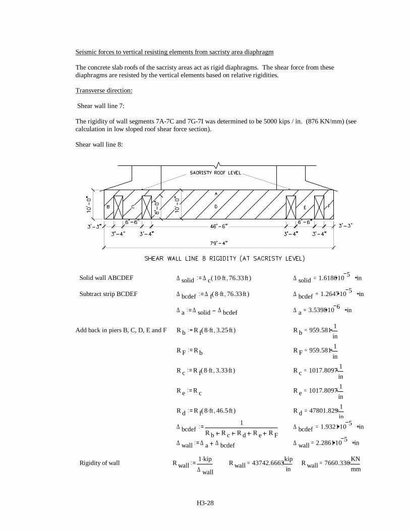
Seismic forces to vertical resisting elements from sacristy area diaphragm
The concrete slab roofs of the sacristy areas act as rigid diaphragms. The shear force from thesediaphragms are resisted by the vertical elements based on relative rigidities.
Transverse direction:
Shear wall line 7:
The rigidity of wall segments 7A-7C and 7G-7I was determined to be 5000 kips / in. (876 KN/mm) (seecalculation in low sloped roof shear force section).
Shear wall line 8:
Solid wall ABCDEF ∆ solid ∆ c 10 ft. 76.33ft,( ) ∆ solid 1.618610 5 in=
Subtract strip BCDEF ∆ bcdef ∆ f 8 ft. 76.33ft.,( ) ∆ bcdef 1.264710 5 in=
∆ a ∆ solid ∆ bcdef ∆ a 3.539810 6 in=
Add back in piers B, C, D, E and F R b R f 8 ft. 3.25 ft.,( ) R b 959.581 1in
=
R F R b R F 959.581 1in
=
R c R f 8 ft. 3.33 ft.,( ) R c 1017.8097 1in
=
R e R c R e 1017.8097 1in
=
R d R f 8 ft. 46.5 ft.,( ) R d 47801.829 1in
=
∆ bcdef1
R b R c R d R e R F∆ bcdef 1.932110 5 in=
∆ wall ∆ a ∆ bcdef ∆ wall 2.286110 5 in=
Rigidity of wall R wall1 kip.
∆ wallR wall 43742.6663kip
in= R wall 7660.336 KN
mm=
H3-29
Shear wall line 8 receives shear from both sacristy areas. Therefore, it is assumed that ½ of the rigidity ofthe entire wall (=1/2 * 43743 = 21872 k/in) will be used in determining the distribution of forces tovertical resisting elements tributary to each sacristy area.
For each sacristy; Rwall 7 = 5000 kips / in (876 KN/mm) Rwall 8 = 21872 kips /in (7660 KN/mm)
Shear force tributary to each sacristy = 5.3 kips (23.6 KN)
R7 = 5000 kips / in R8 = 21872 kips / in V VR
Relement
element= ∑V7A-7C = 5.3(5000) / (21872+5000) = 0.99 kips (4.40 KN)V8= 5.3(21872)/(21872+5000) = 4.31 kips (19.2 KN)
Due to symmetry, V7G-7I = V7A-7C = 0.99 kips (4.40 KN)
Total shear to wall line 8 (for forces trib. to sacristies) = 2(4.31 k) = 8.62 kips (38.3 KN)
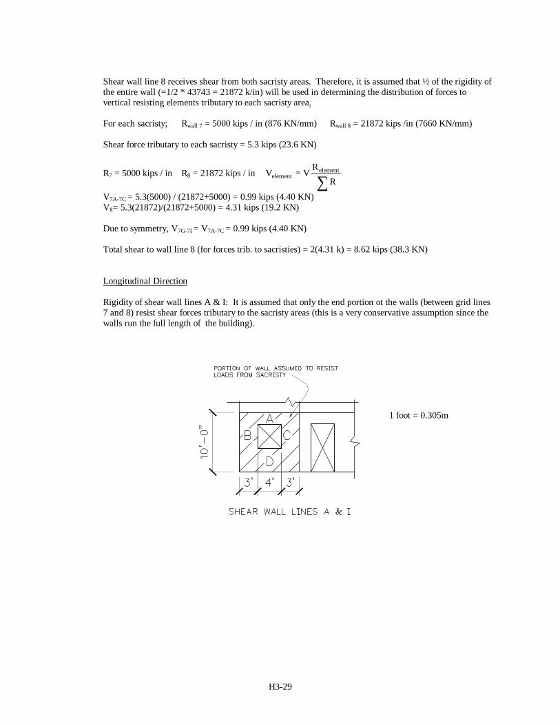
Longitudinal Direction
Rigidity of shear wall lines A & I: It is assumed that only the end portion ot the walls (between grid lines7 and 8) resist shear forces tributary to the sacristy areas (this is a very conservative assumption since thewalls run the full length of the building).
1 foot = 0.305m
H3-30
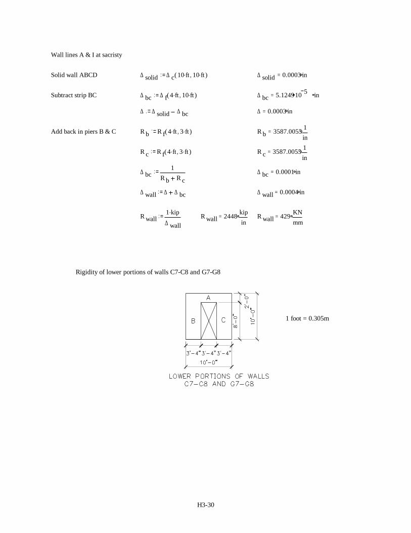
Wall lines A & I at sacristy
Solid wall ABCD ∆ solid ∆ c 10 ft. 10 ft.,( ) ∆ solid 0.0003 in=
Subtract strip BC ∆ bc ∆ f 4 ft. 10 ft.,( ) ∆ bc 5.124910 5 in=
∆ ∆ solid ∆ bc ∆ 0.0003 in=
Add back in piers B & C R b R f 4 ft. 3 ft.,( ) R b 3587.0055 1in
=
R c R f 4 ft. 3 ft.,( ) R c 3587.0055 1in
=
∆ bc1
R b R c∆ bc 0.0001 in=
∆ wall ∆ ∆ bc ∆ wall 0.0004 in=
R wall1 kip.
∆ wallR wall 2448 kip
in= R wall 429 KN
mm=
Rigidity of lower portions of walls C7-C8 and G7-G8
1 foot = 0.305m
H3-31
Solid wall ABCD ∆ solid ∆ c 10 ft. 10 ft.,( ) ∆ solid 0.0003 in=
Subtract strip BCD ∆ bcd ∆ f 8 ft. 10 ft.,( ) ∆ bcd 0.0001 in=
∆ a ∆ solid ∆ bcd ∆ a 0.0002 in=
Add back in piers B and C R b R f 8 ft. 3.33 ft.,( ) R b 1017.8097 1in
=
R c R b R c 1017.8097 1in
=
∆ bc1
R b R c∆ bc 0.0005 in=
∆ total ∆ a ∆ bc ∆ total 0.0007 in=
Rigidity of wall R wall1 kip.
∆ totalR wall 1449.6 kip
in= R wall 253.9 KN
mm=
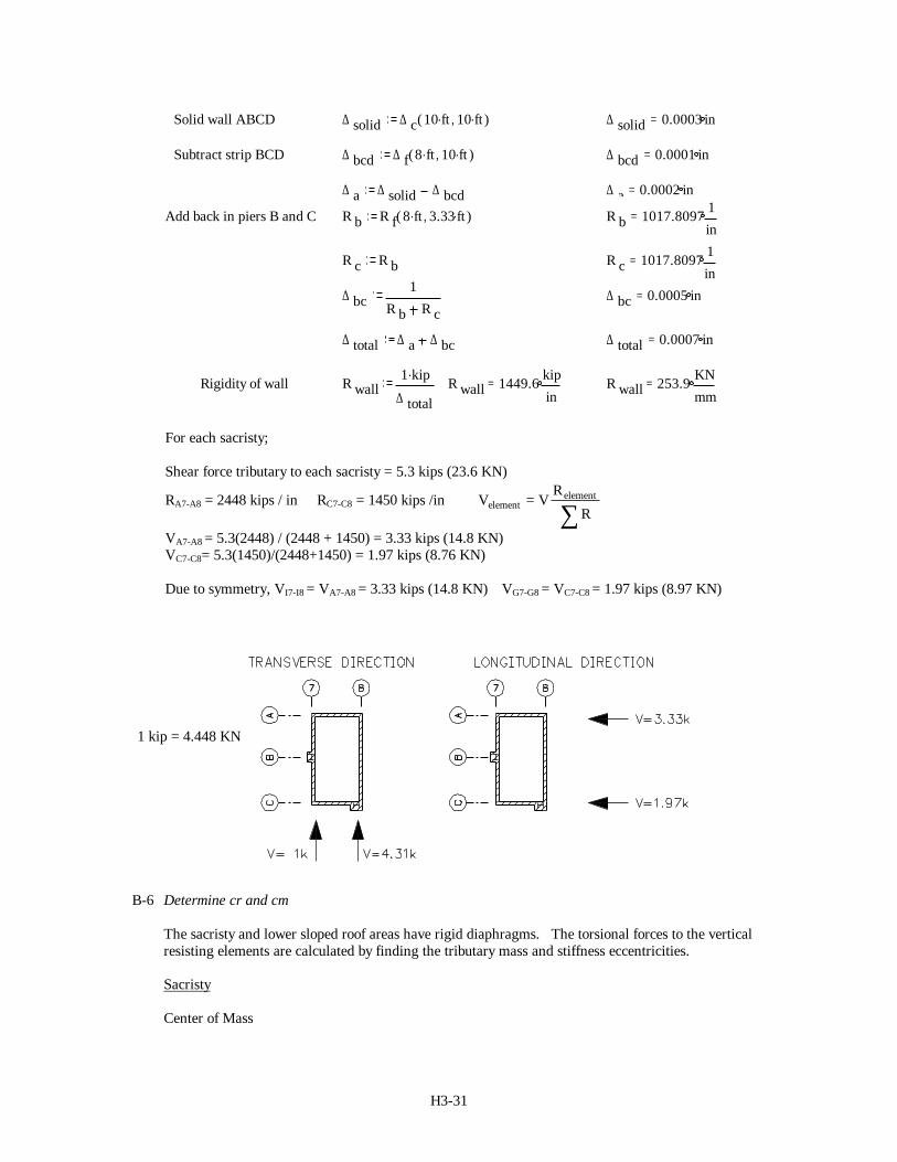
For each sacristy;
Shear force tributary to each sacristy = 5.3 kips (23.6 KN)
RA7-A8 = 2448 kips / in RC7-C8 = 1450 kips /in V VR
Relement
element= ∑VA7-A8 = 5.3(2448) / (2448 + 1450) = 3.33 kips (14.8 KN)VC7-C8= 5.3(1450)/(2448+1450) = 1.97 kips (8.76 KN)
Due to symmetry, VI7-I8 = VA7-A8 = 3.33 kips (14.8 KN) VG7-G8 = VC7-C8 = 1.97 kips (8.97 KN)
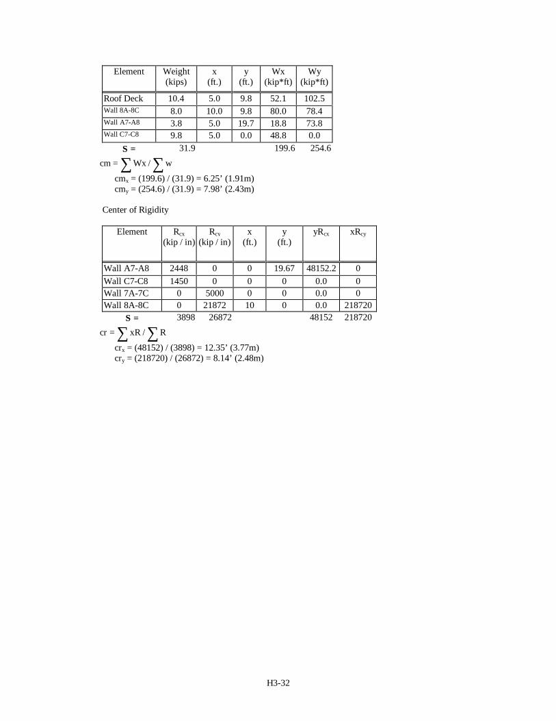
B-6 Determine cr and cm
The sacristy and lower sloped roof areas have rigid diaphragms. The torsional forces to the verticalresisting elements are calculated by finding the tributary mass and stiffness eccentricities.
Sacristy
Center of Mass
1 kip = 4.448 KN
H3-32
Element Weight(kips)
x(ft.)
y(ft.)
Wx(kip*ft)
Wy(kip*ft)
Roof Deck 10.4 5.0 9.8 52.1 102.5Wall 8A-8C 8.0 10.0 9.8 80.0 78.4Wall A7-A8 3.8 5.0 19.7 18.8 73.8Wall C7-C8 9.8 5.0 0.0 48.8 0.0
Σ = 31.9 199.6 254.6
cm Wx w= ∑∑ /
cmx = (199.6) / (31.9) = 6.25’ (1.91m)cmy = (254.6) / (31.9) = 7.98’ (2.43m)
Center of Rigidity
Element Rcx(kip / in)
Rcy(kip / in)
x(ft.)
y(ft.)
yRcx xRcy
Wall A7-A8 2448 0 0 19.67 48152.2 0Wall C7-C8 1450 0 0 0 0.0 0Wall 7A-7C 0 5000 0 0 0.0 0Wall 8A-8C 0 21872 10 0 0.0 218720
Σ = 3898 26872 48152 218720
cr xR R= ∑∑ /
crx = (48152) / (3898) = 12.35’ (3.77m) cry = (218720) / (26872) = 8.14’ (2.48m)
H3-33
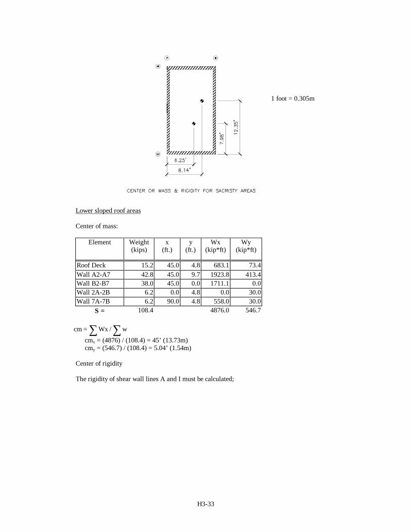
Lower sloped roof areas
Center of mass:
Element Weight(kips)
x(ft.)
y(ft.)
Wx(kip*ft)
Wy(kip*ft)
Roof Deck 15.2 45.0 4.8 683.1 73.4Wall A2-A7 42.8 45.0 9.7 1923.8 413.4Wall B2-B7 38.0 45.0 0.0 1711.1 0.0Wall 2A-2B 6.2 0.0 4.8 0.0 30.0Wall 7A-7B 6.2 90.0 4.8 558.0 30.0
Σ = 108.4 4876.0 546.7
cm Wx w= ∑∑ /
cmx = (4876) / (108.4) = 45’ (13.73m)cmy = (546.7) / (108.4) = 5.04’ (1.54m)
Center of rigidity
The rigidity of shear wall lines A and I must be calculated;
1 foot = 0.305m
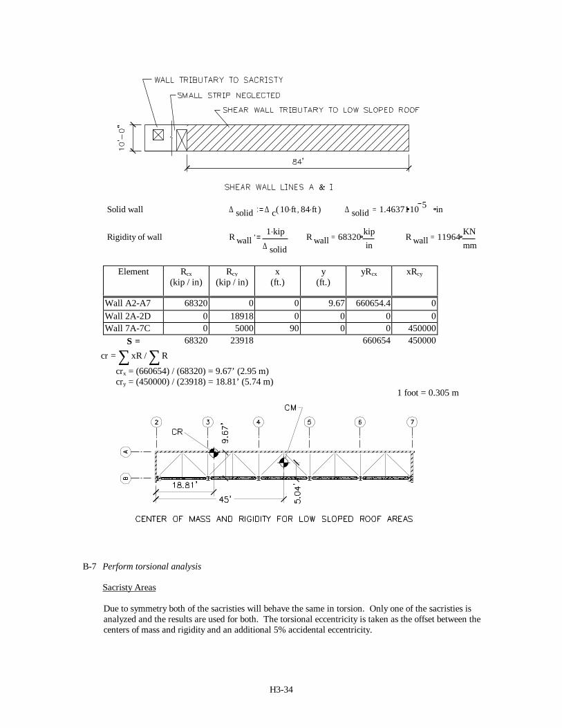
H3-34
Solid wall ∆ solid ∆ c 10 ft. 84 ft.,( ) ∆ solid 1.4637110 5 in=
Rigidity of wall R wall1 kip.
∆ solidR wall 68320 kip
in= R wall 11964 KN
mm=
Element Rcx(kip / in)
Rcy(kip / in)
x(ft.)
y(ft.)
yRcx xRcy
Wall A2-A7 68320 0 0 9.67 660654.4 0Wall 2A-2D 0 18918 0 0 0 0Wall 7A-7C 0 5000 90 0 0 450000
Σ = 68320 23918 660654 450000
cr xR R= ∑∑ /
crx = (660654) / (68320) = 9.67’ (2.95 m) cry = (450000) / (23918) = 18.81’ (5.74 m)
B-7 Perform torsional analysis
Sacristy Areas
Due to symmetry both of the sacristies will behave the same in torsion. Only one of the sacristies isanalyzed and the results are used for both. The torsional eccentricity is taken as the offset between thecenters of mass and rigidity and an additional 5% accidental eccentricity.
1 foot = 0.305 m
H3-35
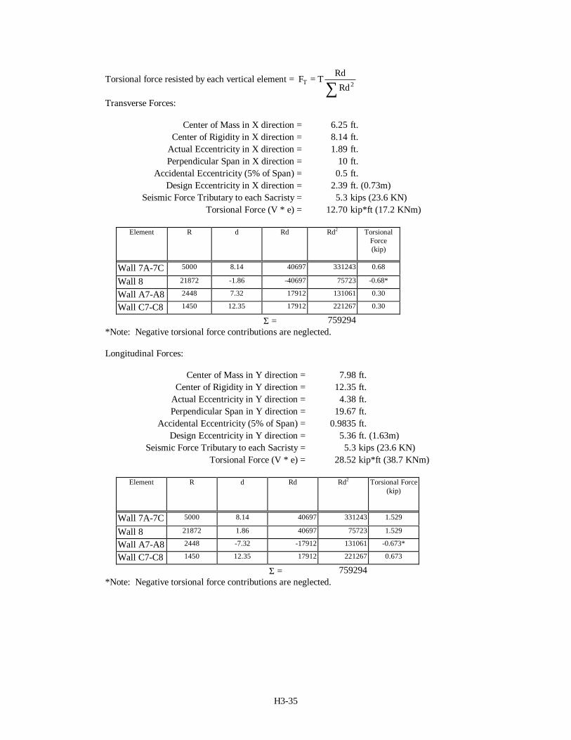
Torsional force resisted by each vertical element = F TRdRd
T = ∑ 2
Transverse Forces:
Center of Mass in X direction = 6.25 ft.Center of Rigidity in X direction = 8.14 ft.
Actual Eccentricity in X direction = 1.89 ft.Perpendicular Span in X direction = 10 ft.
Accidental Eccentricity (5% of Span) = 0.5 ft.Design Eccentricity in X direction = 2.39 ft. (0.73m)
Seismic Force Tributary to each Sacristy = 5.3 kips (23.6 KN)Torsional Force (V * e) = 12.70 kip*ft (17.2 KNm)
Element R d Rd Rd2 TorsionalForce(kip)
Wall 7A-7C 5000 8.14 40697 331243 0.68
Wall 8 21872 -1.86 -40697 75723 -0.68*
Wall A7-A8 2448 7.32 17912 131061 0.30
Wall C7-C8 1450 12.35 17912 221267 0.30
Σ = 759294*Note: Negative torsional force contributions are neglected.
Longitudinal Forces:
Center of Mass in Y direction = 7.98 ft.Center of Rigidity in Y direction = 12.35 ft.
Actual Eccentricity in Y direction = 4.38 ft.Perpendicular Span in Y direction = 19.67 ft.
Accidental Eccentricity (5% of Span) = 0.9835 ft.Design Eccentricity in Y direction = 5.36 ft. (1.63m)
Seismic Force Tributary to each Sacristy = 5.3 kips (23.6 KN)Torsional Force (V * e) = 28.52 kip*ft (38.7 KNm)
Element R d Rd Rd2 Torsional Force(kip)
Wall 7A-7C 5000 8.14 40697 331243 1.529
Wall 8 21872 1.86 40697 75723 1.529
Wall A7-A8 2448 -7.32 -17912 131061 -0.673*
Wall C7-C8 1450 12.35 17912 221267 0.673
Σ = 759294*Note: Negative torsional force contributions are neglected.
H3-36
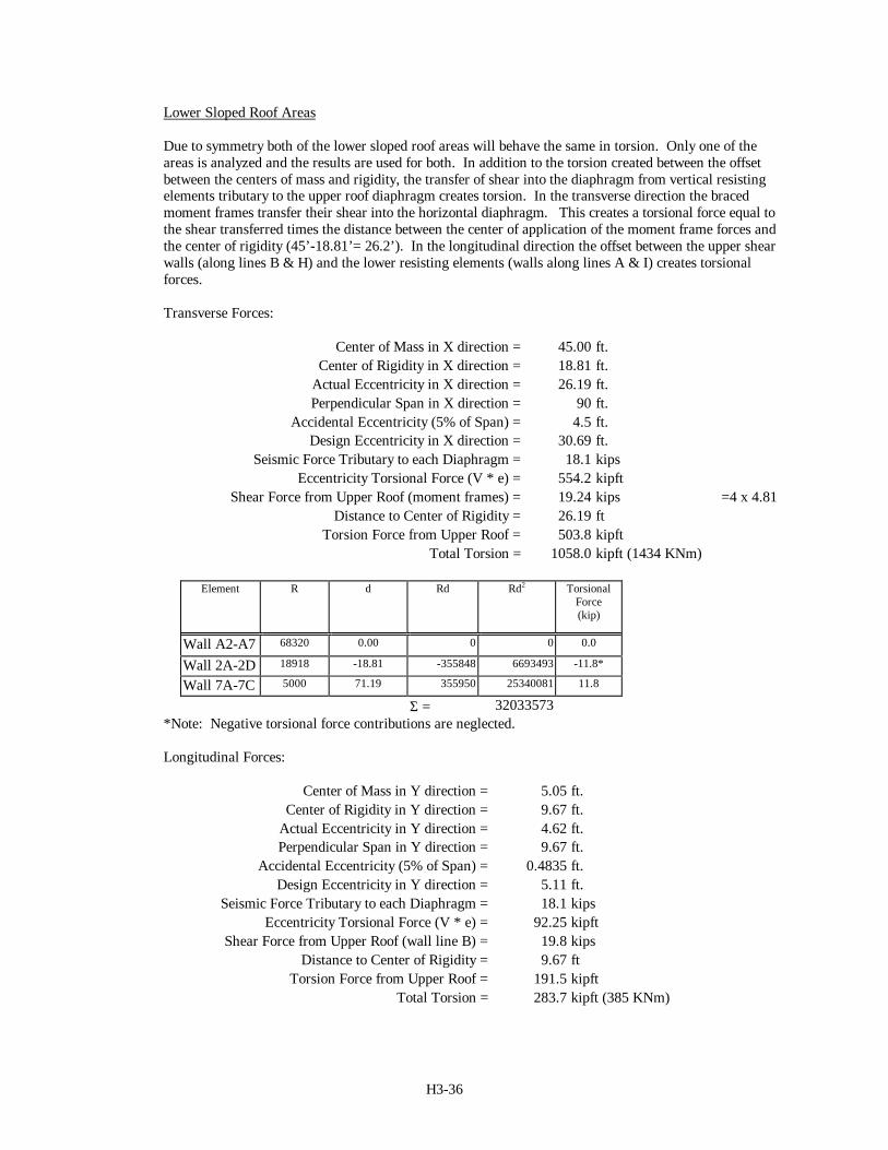
Lower Sloped Roof Areas
Due to symmetry both of the lower sloped roof areas will behave the same in torsion. Only one of theareas is analyzed and the results are used for both. In addition to the torsion created between the offsetbetween the centers of mass and rigidity, the transfer of shear into the diaphragm from vertical resistingelements tributary to the upper roof diaphragm creates torsion. In the transverse direction the bracedmoment frames transfer their shear into the horizontal diaphragm. This creates a torsional force equal tothe shear transferred times the distance between the center of application of the moment frame forces andthe center of rigidity (45’-18.81’= 26.2’). In the longitudinal direction the offset between the upper shearwalls (along lines B & H) and the lower resisting elements (walls along lines A & I) creates torsionalforces.
Transverse Forces:
Center of Mass in X direction = 45.00 ft.Center of Rigidity in X direction = 18.81 ft.
Actual Eccentricity in X direction = 26.19 ft.Perpendicular Span in X direction = 90 ft.
Accidental Eccentricity (5% of Span) = 4.5 ft.Design Eccentricity in X direction = 30.69 ft.
Seismic Force Tributary to each Diaphragm = 18.1 kipsEccentricity Torsional Force (V * e) = 554.2 kipft
Shear Force from Upper Roof (moment frames) = 19.24 kips =4 x 4.81Distance to Center of Rigidity = 26.19 ft
Torsion Force from Upper Roof = 503.8 kipftTotal Torsion = 1058.0 kipft (1434 KNm)
Element R d Rd Rd2 TorsionalForce(kip)
Wall A2-A7 68320 0.00 0 0 0.0
Wall 2A-2D 18918 -18.81 -355848 6693493 -11.8*
Wall 7A-7C 5000 71.19 355950 25340081 11.8
Σ = 32033573*Note: Negative torsional force contributions are neglected.
Longitudinal Forces:
Center of Mass in Y direction = 5.05 ft.Center of Rigidity in Y direction = 9.67 ft.
Actual Eccentricity in Y direction = 4.62 ft.Perpendicular Span in Y direction = 9.67 ft.
Accidental Eccentricity (5% of Span) = 0.4835 ft.Design Eccentricity in Y direction = 5.11 ft.
Seismic Force Tributary to each Diaphragm = 18.1 kipsEccentricity Torsional Force (V * e) = 92.25 kipft
Shear Force from Upper Roof (wall line B) = 19.8 kipsDistance to Center of Rigidity = 9.67 ft
Torsion Force from Upper Roof = 191.5 kipftTotal Torsion = 283.7 kipft (385 KNm)
H3-37
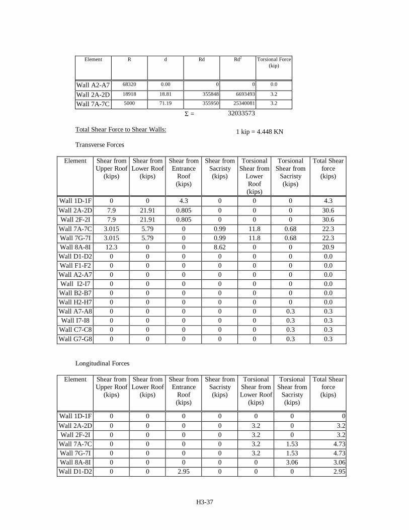
Element R d Rd Rd2 Torsional Force(kip)
Wall A2-A7 68320 0.00 0 0 0.0
Wall 2A-2D 18918 18.81 355848 6693493 3.2
Wall 7A-7C 5000 71.19 355950 25340081 3.2
Σ = 32033573
Total Shear Force to Shear Walls:
Transverse Forces
Element Shear fromUpper Roof
(kips)
Shear fromLower Roof
(kips)
Shear fromEntrance
Roof(kips)
Shear fromSacristy(kips)
TorsionalShear from
LowerRoof(kips)
TorsionalShear from
Sacristy(kips)
Total Shearforce(kips)
Wall 1D-1F 0 0 4.3 0 0 0 4.3Wall 2A-2D 7.9 21.91 0.805 0 0 0 30.6Wall 2F-2I 7.9 21.91 0.805 0 0 0 30.6
Wall 7A-7C 3.015 5.79 0 0.99 11.8 0.68 22.3Wall 7G-7I 3.015 5.79 0 0.99 11.8 0.68 22.3Wall 8A-8I 12.3 0 0 8.62 0 0 20.9Wall D1-D2 0 0 0 0 0 0 0.0Wall F1-F2 0 0 0 0 0 0 0.0Wall A2-A7 0 0 0 0 0 0 0.0Wall I2-I7 0 0 0 0 0 0 0.0Wall B2-B7 0 0 0 0 0 0 0.0Wall H2-H7 0 0 0 0 0 0 0.0Wall A7-A8 0 0 0 0 0 0.3 0.3Wall I7-I8 0 0 0 0 0 0.3 0.3
Wall C7-C8 0 0 0 0 0 0.3 0.3Wall G7-G8 0 0 0 0 0 0.3 0.3
Longitudinal Forces
Element Shear fromUpper Roof
(kips)
Shear fromLower Roof
(kips)
Shear fromEntrance
Roof(kips)
Shear fromSacristy(kips)
TorsionalShear fromLower Roof
(kips)
TorsionalShear from
Sacristy(kips)
Total Shearforce(kips)
Wall 1D-1F 0 0 0 0 0 0 0Wall 2A-2D 0 0 0 0 3.2 0 3.2Wall 2F-2I 0 0 0 0 3.2 0 3.2
Wall 7A-7C 0 0 0 0 3.2 1.53 4.73Wall 7G-7I 0 0 0 0 3.2 1.53 4.73Wall 8A-8I 0 0 0 0 0 3.06 3.06Wall D1-D2 0 0 2.95 0 0 0 2.95
1 kip = 4.448 KN
H3-38
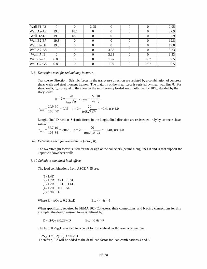
Wall F1-F2 0 0 2.95 0 0 0 2.95Wall A2-A7 19.8 18.1 0 0 0 0 37.9Wall I2-I7 19.8 18.1 0 0 0 0 37.9Wall B2-B7 19.8 0 0 0 0 0 19.8Wall H2-H7 19.8 0 0 0 0 0 19.8Wall A7-A8 0 0 0 3.33 0 0 3.33Wall I7-I8 0 0 0 3.33 0 0 3.33
Wall C7-C8 6.86 0 0 1.97 0 0.67 9.5Wall G7-G8 6.86 0 0 1.97 0 0.67 9.5
B-8 Determine need for redundancy factor, ρ.
Transverse Direction: Seismic forces in the transverse direction are resisted by a combination of concreteshear walls and steel moment frames. The majority of the shear force is resisted by shear wall line 8. Forshear walls, rmax is equal to the shear in the most heavily loaded wall multiplied by 10/lw, divided by thestory shear:
ρ = −220
r Amax
, rVV lT w
max = 10
rmax.
'.= =20 9
1061040
0 05 , ρ = − = −220
0 05 81742 4
.. , use 1.0
Longitudinal Direction Seismic forces in the longitudinal direction are resisted entirely by concrete shearwalls.
rmax. .= =57 7
1061084
0 065 , ρ = − = −220
0 065 8174140
.. , use 1.0
B-9 Determine need for overstrength factor, Ωo
The overstrength factor is used for the design of the collectors (beams along lines B and H that support theupper window/shear walls.
B-10 Calculate combined load effects
The load combinations from ASCE 7-95 are:
(1) 1.4D (2) 1.2D + 1.6L + 0.5Lr (3) 1.2D + 0.5L + 1.6Lr (4) 1.2D + E + 0.5L (5) 0.9D + E
Where E = ρQE ± 0.2 SDSD Eq. 4-4 & 4-5
When specifically required by FEMA 302 (Collectors, their connections, and bracing connections for thisexample) the design seismic force is defined by: E = Ω0QE ± 0.2SDSD Eq. 4-6 & 4-7
The term 0.2SDSD is added to account for the vertical earthquake accelerations.
0.2SDSD = 0.2(1.0)D = 0.2 D Therefore, 0.2 will be added to the dead load factor for load combinations 4 and 5.
H3-39
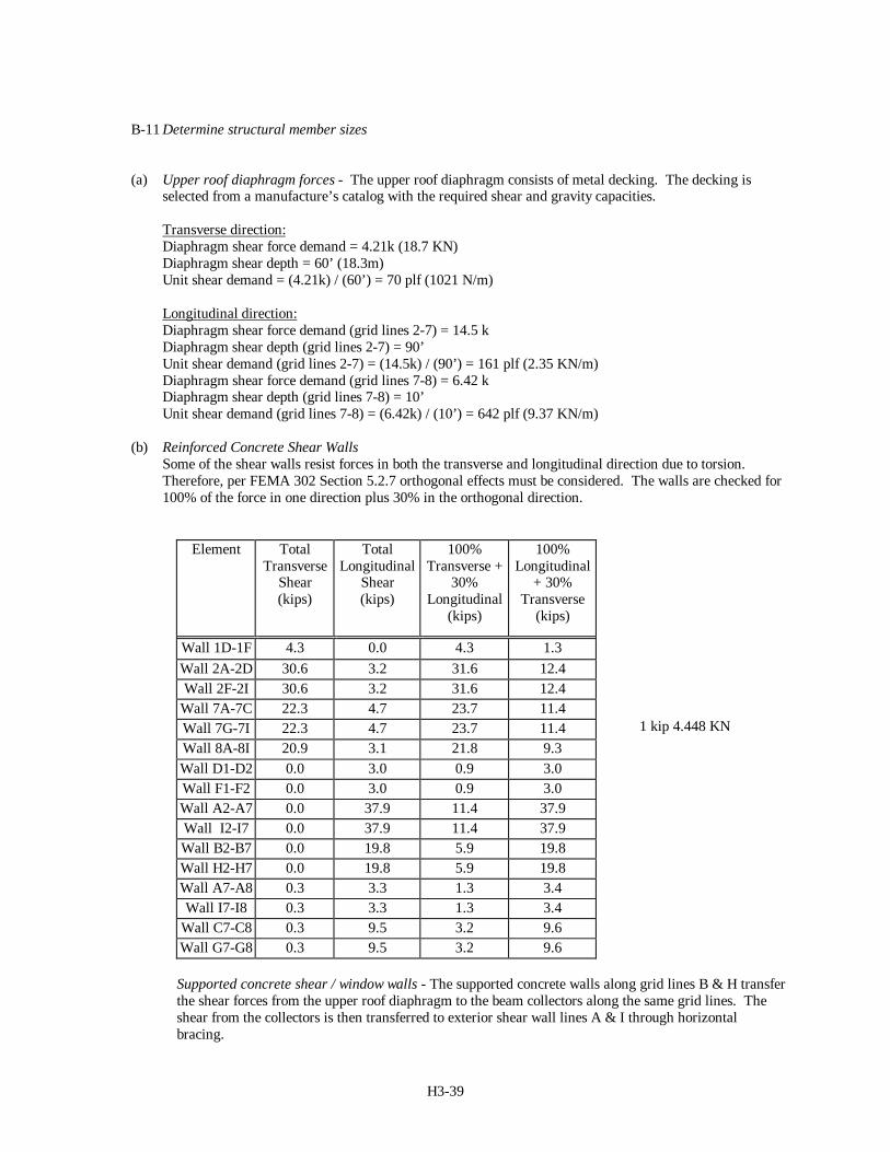
B-11 Determine structural member sizes
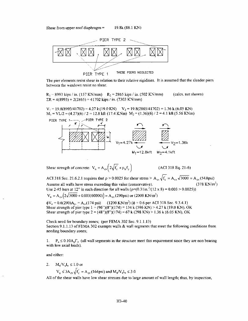
(a) Upper roof diaphragm forces - The upper roof diaphragm consists of metal decking. The decking isselected from a manufacture’s catalog with the required shear and gravity capacities.
Transverse direction:Diaphragm shear force demand = 4.21k (18.7 KN)Diaphragm shear depth = 60’ (18.3m)Unit shear demand = (4.21k) / (60’) = 70 plf (1021 N/m)
Longitudinal direction:Diaphragm shear force demand (grid lines 2-7) = 14.5 kDiaphragm shear depth (grid lines 2-7) = 90’Unit shear demand (grid lines 2-7) = (14.5k) / (90’) = 161 plf (2.35 KN/m)Diaphragm shear force demand (grid lines 7-8) = 6.42 kDiaphragm shear depth (grid lines 7-8) = 10’Unit shear demand (grid lines 7-8) = (6.42k) / (10’) = 642 plf (9.37 KN/m)
(b) Reinforced Concrete Shear WallsSome of the shear walls resist forces in both the transverse and longitudinal direction due to torsion.Therefore, per FEMA 302 Section 5.2.7 orthogonal effects must be considered. The walls are checked for100% of the force in one direction plus 30% in the orthogonal direction.
Element TotalTransverse
Shear(kips)
TotalLongitudinal
Shear(kips)
100%Transverse +
30%Longitudinal
(kips)
100%Longitudinal
+ 30%Transverse
(kips)
Wall 1D-1F 4.3 0.0 4.3 1.3Wall 2A-2D 30.6 3.2 31.6 12.4Wall 2F-2I 30.6 3.2 31.6 12.4
Wall 7A-7C 22.3 4.7 23.7 11.4Wall 7G-7I 22.3 4.7 23.7 11.4Wall 8A-8I 20.9 3.1 21.8 9.3Wall D1-D2 0.0 3.0 0.9 3.0Wall F1-F2 0.0 3.0 0.9 3.0Wall A2-A7 0.0 37.9 11.4 37.9Wall I2-I7 0.0 37.9 11.4 37.9Wall B2-B7 0.0 19.8 5.9 19.8Wall H2-H7 0.0 19.8 5.9 19.8Wall A7-A8 0.3 3.3 1.3 3.4Wall I7-I8 0.3 3.3 1.3 3.4
Wall C7-C8 0.3 9.5 3.2 9.6Wall G7-G8 0.3 9.5 3.2 9.6
Supported concrete shear / window walls - The supported concrete walls along grid lines B & H transferthe shear forces from the upper roof diaphragm to the beam collectors along the same grid lines. Theshear from the collectors is then transferred to exterior shear wall lines A & I through horizontalbracing.
1 kip 4.448 KN
H3-41
the V A f A psiu cv c cv≤ =3 164' ( ) term is satisfied. Therefore, no boundary zones will be required in
any wall segment if Mu/Vulw ≤ 3.0 is satisfied.Pier 1 M/Vl = 12.8/4.27(8) = 0.37 <3.0 (No boundary zones required)Pier 2 M/Vl = 4.1/1.36(4) = 0.75 <3.0 (No boundary zones required)
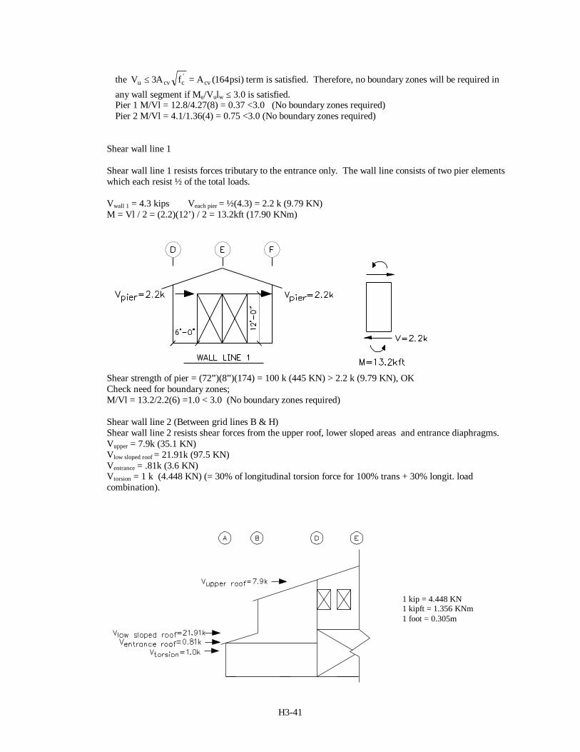
Shear wall line 1
Shear wall line 1 resists forces tributary to the entrance only. The wall line consists of two pier elementswhich each resist ½ of the total loads.
Vwall 1 = 4.3 kips Veach pier = ½(4.3) = 2.2 k (9.79 KN)M = Vl / 2 = (2.2)(12’) / 2 = 13.2kft (17.90 KNm)
Shear strength of pier = (72”)(8”)(174) = 100 k (445 KN) > 2.2 k (9.79 KN), OKCheck need for boundary zones;M/Vl = 13.2/2.2(6) =1.0 < 3.0 (No boundary zones required)
Shear wall line 2 (Between grid lines B & H)Shear wall line 2 resists shear forces from the upper roof, lower sloped areas and entrance diaphragms.Vupper = 7.9k (35.1 KN)Vlow sloped roof = 21.91k (97.5 KN)Ventrance = .81k (3.6 KN)Vtorsion = 1 k (4.448 KN) (= 30% of longitudinal torsion force for 100% trans + 30% longit. loadcombination).
1 kip = 4.448 KN1 kipft = 1.356 KNm1 foot = 0.305m
H3-42
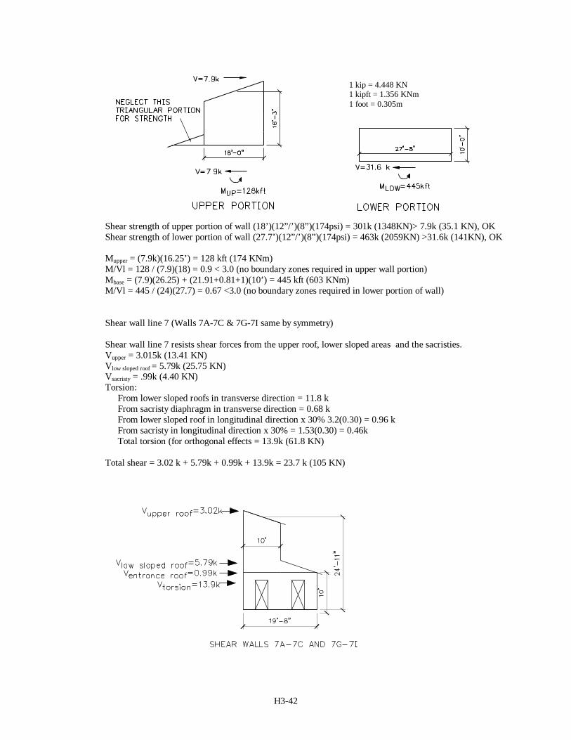
Shear strength of upper portion of wall (18’)(12”/’)(8”)(174psi) = 301k (1348KN)> 7.9k (35.1 KN), OKShear strength of lower portion of wall (27.7’)(12”/’)(8”)(174psi) = 463k (2059KN) >31.6k (141KN), OK
Mupper = (7.9k)(16.25’) = 128 kft (174 KNm)M/Vl = 128 / (7.9)(18) = 0.9 < 3.0 (no boundary zones required in upper wall portion)Mbase = (7.9)(26.25) + (21.91+0.81+1)(10’) = 445 kft (603 KNm)M/Vl = 445 / (24)(27.7) = 0.67 <3.0 (no boundary zones required in lower portion of wall)
Shear wall line 7 (Walls 7A-7C & 7G-7I same by symmetry)
Shear wall line 7 resists shear forces from the upper roof, lower sloped areas and the sacristies.Vupper = 3.015k (13.41 KN)Vlow sloped roof = 5.79k (25.75 KN)Vsacristy = .99k (4.40 KN)Torsion:
From lower sloped roofs in transverse direction = 11.8 kFrom sacristy diaphragm in transverse direction = 0.68 kFrom lower sloped roof in longitudinal direction x 30% 3.2(0.30) = 0.96 kFrom sacristy in longitudinal direction x 30% = 1.53(0.30) = 0.46kTotal torsion (for orthogonal effects = 13.9k (61.8 KN)
Total shear = 3.02 k + 5.79k + 0.99k + 13.9k = 23.7 k (105 KN)
1 kip = 4.448 KN1 kipft = 1.356 KNm1 foot = 0.305m
H3-43
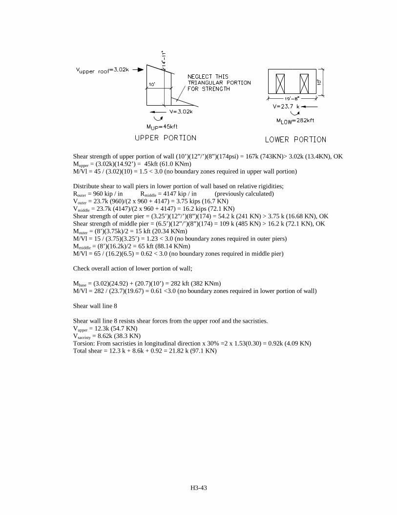
Shear strength of upper portion of wall (10’)(12”/’)(8”)(174psi) = 167k (743KN)> 3.02k (13.4KN), OKMupper = (3.02k)(14.92’) = 45kft (61.0 KNm)M/Vl = 45 / (3.02)(10) = 1.5 < 3.0 (no boundary zones required in upper wall portion)
Distribute shear to wall piers in lower portion of wall based on relative rigidities;Router = 960 kip / in Rmiddle = 4147 kip / in (previously calculated)Vouter = 23.7k (960)/(2 x 960 + 4147) = 3.75 kips (16.7 KN)Vmiddle = 23.7k (4147)/(2 x 960 + 4147) = 16.2 kips (72.1 KN)Shear strength of outer pier = (3.25’)(12”/’)(8”)(174) = 54.2 k (241 KN) > 3.75 k (16.68 KN), OKShear strength of middle pier = (6.5’)(12”/’)(8”)(174) = 109 k (485 KN) > 16.2 k (72.1 KN), OKMouter = (8’)(3.75k)/2 = 15 kft (20.34 KNm)M/Vl = 15 / (3.75)(3.25’) = 1.23 < 3.0 (no boundary zones required in outer piers)Mmiddle = (8’)(16.2k)/2 = 65 kft (88.14 KNm)M/Vl = 65 / (16.2)(6.5) = 0.62 < 3.0 (no boundary zones required in middle pier)
Check overall action of lower portion of wall;
Mbase = (3.02)(24.92) + (20.7)(10’) = 282 kft (382 KNm)M/Vl = 282 / (23.7)(19.67) = 0.61 <3.0 (no boundary zones required in lower portion of wall)
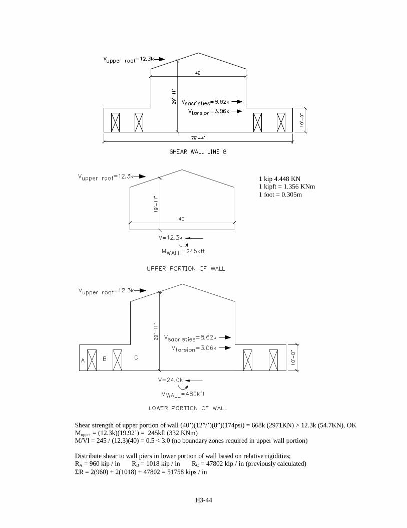
Shear wall line 8
Shear wall line 8 resists shear forces from the upper roof and the sacristies.Vupper = 12.3k (54.7 KN)Vsacristy = 8.62k (38.3 KN)Torsion: From sacristies in longitudinal direction x 30% =2 x 1.53(0.30) = 0.92k (4.09 KN)Total shear = 12.3 k + 8.6k + 0.92 = 21.82 k (97.1 KN)
H3-44
Shear strength of upper portion of wall (40’)(12”/’)(8”)(174psi) = 668k (2971KN) > 12.3k (54.7KN), OKMupper = (12.3k)(19.92’) = 245kft (332 KNm)M/Vl = 245 / (12.3)(40) = 0.5 < 3.0 (no boundary zones required in upper wall portion)
Distribute shear to wall piers in lower portion of wall based on relative rigidities;RA = 960 kip / in RB = 1018 kip / in RC = 47802 kip / in (previously calculated)ΣR = 2(960) + 2(1018) + 47802 = 51758 kips / in
1 kip 4.448 KN1 kipft = 1.356 KNm1 foot = 0.305m
H3-45
VA = 24.0k (960)/(51758) = 0.45 kips (2.00 KN)VB = 24.0k (1018)/(51758) = 0.47 kips (2.09 KN)Vc = 24.0k (47802)/(51758) = 22.2 kips (98.7 KN)Shear strength of pier A= (3.25’)(12”/’)(8”)(174) = 54.2k (241KN) > 0.45k (2.00 KN), OKShear strength of pier B= (3.33’)(12”/’)(8”)(174) = 55.6k (247KN) > 0.47k (2.09 KN), OKShear strength of pier C= (46.5’)(12”/’)(8”)(174) = 777 k > 22.2 k, OKMA = (8’)(.45)/2 = 1.8 kft (2.44 KNm)M/Vl = (1.8) / (0.45)(3.25) = 1.23 < 3.0 (no boundary zone required)MB = (8’)(.47)/2 = 1.9 kft (2.58 KNm)M/Vl = (1.9) / (0.47)(3.33) = 1.23 < 3.0 (no boundary zone required)MC = (8’)(22.2)/2 = 89 kft (121 KNm)M/Vl = 89 / (22.2)(46.5’) = 0.09 < 3.0 (no boundary zones required in outer piers)
Check overall action of lower portion of wall;
Mbase = (12.3)(29.92) + (11.68)(10’) = 478 kft (648 KNm)M/Vl = 478 / (24)(79.3) = 0.3 <3.0 (no boundary zones required in lower portion of wall)
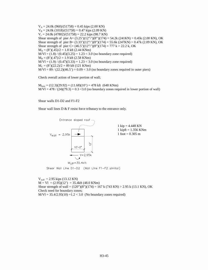
Shear walls D1-D2 and F1-F2
Shear wall lines D & F resist force tributary to the entrance only.
Vwall = 2.95 kips (13.12 KN)M = Vl = (2.95)(12’) = 35.4kft (48.0 KNm)Shear strength of wall = (120”)(8”)(174) = 167 k (743 KN) > 2.95 k (13.1 KN), OKCheck need for boundary zones;M/Vl = 35.4/2.95(10) =1.2 < 3.0 (No boundary zones required)
1 kip = 4.448 KN1 kipft = 1.356 KNm1 foot = 0.305 m
H3-46
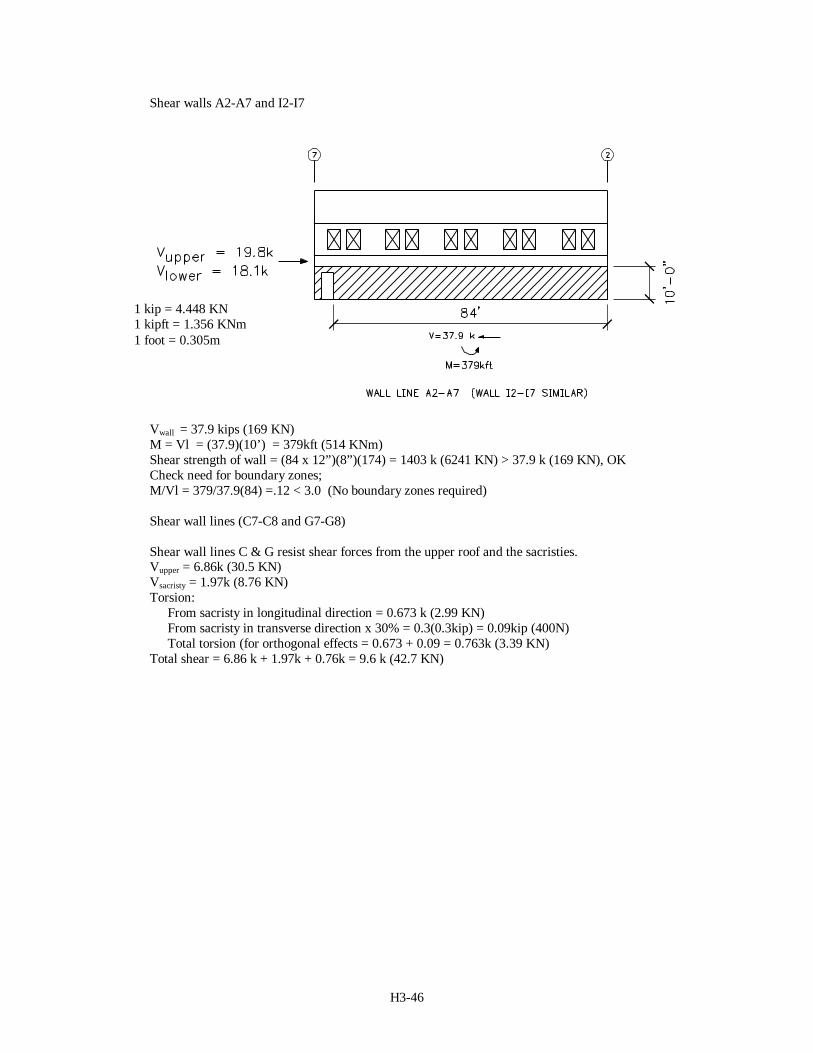
Shear walls A2-A7 and I2-I7
Vwall = 37.9 kips (169 KN)M = Vl = (37.9)(10’) = 379kft (514 KNm)Shear strength of wall = (84 x 12”)(8”)(174) = 1403 k (6241 KN) > 37.9 k (169 KN), OKCheck need for boundary zones;M/Vl = 379/37.9(84) =.12 < 3.0 (No boundary zones required)
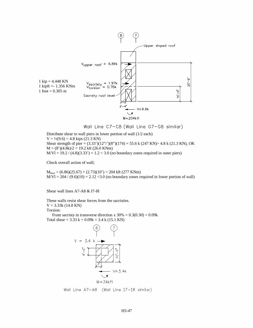
Shear wall lines (C7-C8 and G7-G8)
Shear wall lines C & G resist shear forces from the upper roof and the sacristies.Vupper = 6.86k (30.5 KN)Vsacristy = 1.97k (8.76 KN)Torsion:
From sacristy in longitudinal direction = 0.673 k (2.99 KN)From sacristy in transverse direction x 30% = 0.3(0.3kip) = 0.09kip (400N)Total torsion (for orthogonal effects = 0.673 + 0.09 = 0.763k (3.39 KN)
Total shear = 6.86 k + 1.97k + 0.76k = 9.6 k (42.7 KN)
1 kip = 4.448 KN1 kipft = 1.356 KNm1 foot = 0.305m
H3-47
Distribute shear to wall piers in lower portion of wall (1/2 each)V = ½(9.6) = 4.8 kips (21.3 KN)Shear strength of pier = (3.33’)(12”/’)(8”)(174) = 55.6 k (247 KN)> 4.8 k (21.3 KN), OKM = (8’)(4.8k)/2 = 19.2 kft (26.0 KNm)M/Vl = 19.2 / (4.8)(3.33’) = 1.2 < 3.0 (no boundary zones required in outer piers)
Check overall action of wall;
Mbase = (6.86)(25.67) + (2.73)(10’) = 204 kft (277 KNm)M/Vl = 204 / (9.6)(10) = 2.12 <3.0 (no boundary zones required in lower portion of wall)
Shear wall lines A7-A8 & I7-I8
These walls resist shear forces from the sacristies.V = 3.33k (14.8 KN)Torsion:
From sacristy in transverse direction x 30% = 0.3(0.30) = 0.09kTotal shear = 3.33 k + 0.09k = 3.4 k (15.1 KN)
1 kip = 4.448 KN1 kipft =- 1.356 KNm1 foot = 0.305 m
H3-48
Distribute shear to wall piers in lower portion of wall (1/2 each);V = 3.4k/2 = 1.7 k (7.56 KN)Shear strength of pier = (3’)(12”/’)(8”)(174) = 49 k (218 KN) > 1.7 k (7.56 KN), OKM = (4’)(1.7)/2 = 3.4 kft (4.61 KNm)M/Vl = 3.4 / (1.7)(3’) = 0.67 < 3.0 (no boundary zones required in outer piers)
Check overall action of lower portion of wall;
Mbase = (3.4)(10’) = 34 kft (46.1 KNm)M/Vl = 34 / (3.4)(10) = 1.0 <3.0 (no boundary zones required in lower portion of wall)
Typical Reinforcing; (See Figure 7-6 for typical reinforcing in concrete shear walls)
Use #5 bars @ 12” on center in horizontal and vertical direction for all concrete shear walls.
Development length per ACI 318 Sec. 12.2 ld
f
fd
b
y
c
=αβλ
25 '
α = 1.3, β = 1.0 αβ need not be greater than 0.8, use 0.8λ = 1.0ld
d
b= =60000 08 10
25 300035
( . )( . )
For # 5 bar ld = 35*(5/8) = 22”, use 24” (61 cm)
Use splice length = 1.3 ld = 1.3(24”) = 31.2”, use 32” (81.3cm) for all splices.
Use 2 #5 vertical bars at ends of all wall segments and at openings.Use 2 #5 horizontal bars typical above and below openings (extend bars 24” (61 cm) past edge ofopenings to develop bars) and continuously at top of walls for chord reinforcement.
(d) Horizontal bracing:The bracing resist seismic forces only; load factor = 1.0Design bracing for highest shear force (at shear wall line 2)Shear to wall line 2A-2D passing through horizontal bracing = direct + torsionV = 21.91 kips + 30%(3.2 kips) = 22.9 kips (102 KNm)Axial (braces are at 45 degress); Axial force = 22.9 kips (1.41) = 32.3 kips (144 KN)
Try 4” Extra Strong Round Tubing (fy = 36 ksi, r = 1.48 in., A = 4.41 in.2)
The perpendicular length of the brace is approximately 8’, length of brace = 8’(1.41)=11.3’
KLr
F
Ey
π π= =( . )( . ' )( "/')
( . ).
10 113 12148
3629000
103
φ λc crF ksi ksi= =( . )( )( . ) .085 36 0 658 19 63
2(135 N/mm2)
φcPn = (19.63 ksi)(4.41 in.2) = 86.6 k (385 KN)
Check AISC Seismic Provisions; Design bracing as ordinary concerntrically braced frame (OCBF)
Slenderness: Bracing members shall have Kl/r ≤ = =720 720 6 120/ /Fy (Section 14.2.a)
Kl/r = (1.0)(11.3)(12)/(1.48) = 92 < 120, OK
Required Compressive Strength of brace ≤ 0.8 times φcPn (Section 14.2.b)0.8fcPn = (0.8)(86.6 k) = 69.3 k (308 KN) > 32.3 k (144 KN), OK
H3-49
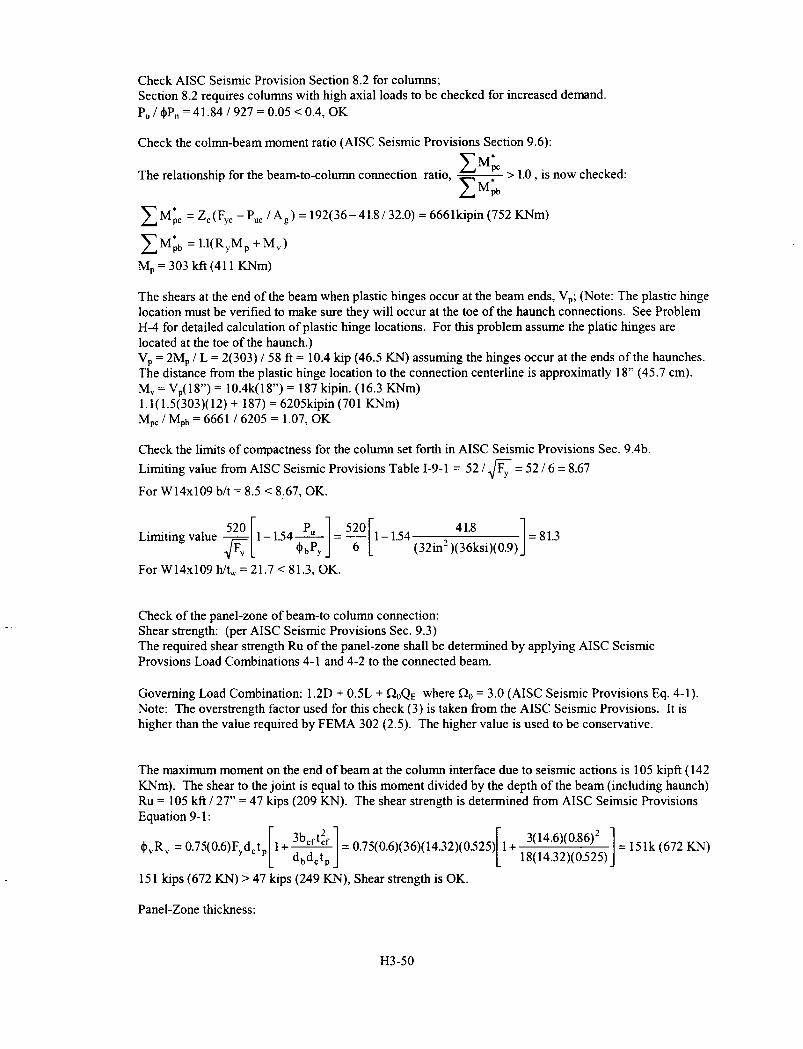
Width-to-Thickness Ratio: (Section 14.2.d)D/t ≤ 1300/Fy = 1300/36 = 36.11 (AISC Seismic Provisions Table I-9-1)D/t = 4.5 / 0.337 = 13.4 < 36.11, OK
(e) Moment frames:The moment frames resist seismic forces from the upper roof diaphragm and are braced by the lowersloped diaphragms (by horizontal bracing). The frames also support gravity loads from the upper roofand from the beam reactions along grid lines B & H.Gravity: Dead = 218 plf (3.18 KN/m) Live = 238 plf (3.47 KN/m) Beam reactions = 23.9 k (106.3 KN)Seismic: Vupper roof =4.81 k (21.4 KN)
The members of the moment frames have already been checked for the gravity load combination andnow are checked for the seismic load combination: 1.2D + 0.5L + 1.0E where E = ρQE + 0. Thevertical seismic effects are captured by the term 0.2 SDSD = 0.2(1.0) = 0.2D. This term is added to the1.2D load term to a total of 1.4D for this load combination.
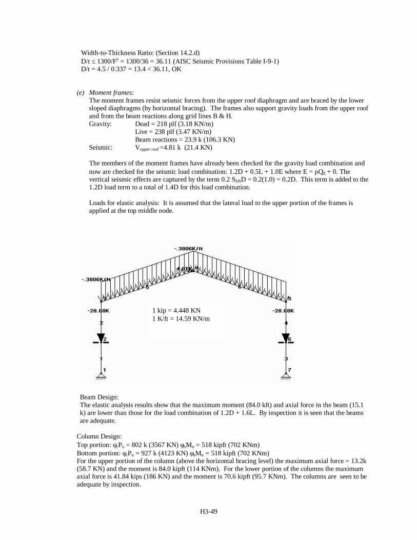
Loads for elastic analysis: It is assumed that the lateral load to the upper portion of the frames isapplied at the top middle node.
Beam Design:The elastic analysis results show that the maximum moment (84.0 kft) and axial force in the beam (15.1k) are lower than those for the load combination of 1.2D + 1.6L. By inspection it is seen that the beamsare adequate.
Column Design:Top portion: φcPn = 802 k (3567 KN) φbMn = 518 kipft (702 KNm)Bottom portion: φcPn = 927 k (4123 KN) φbMn = 518 kipft (702 KNm)For the upper portion of the column (above the horizontal bracing level) the maximum axial force = 13.2k(58.7 KN) and the moment is 84.0 kipft (114 KNm). For the lower portion of the columns the maximumaxial force is 41.84 kips (186 KN) and the moment is 70.6 kipft (95.7 KNm). The columns are seen to beadequate by inspection.
1 kip = 4.448 KN1 K/ft = 14.59 KN/m
H3-52
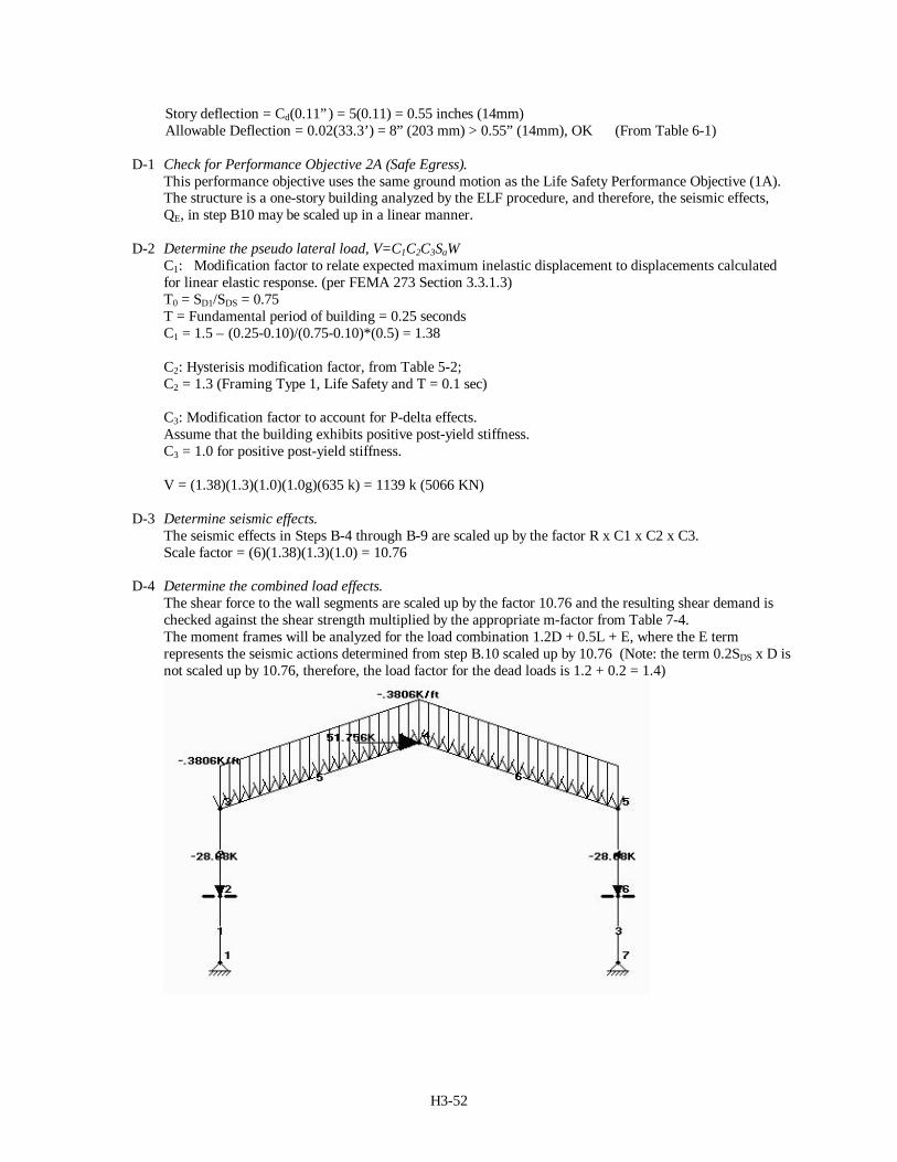
Story deflection = Cd(0.11”) = 5(0.11) = 0.55 inches (14mm)Allowable Deflection = 0.02(33.3’) = 8” (203 mm) > 0.55” (14mm), OK (From Table 6-1)
D-1 Check for Performance Objective 2A (Safe Egress).This performance objective uses the same ground motion as the Life Safety Performance Objective (1A).The structure is a one-story building analyzed by the ELF procedure, and therefore, the seismic effects,QE, in step B10 may be scaled up in a linear manner.
D-2 Determine the pseudo lateral load, V=C1C2C3SaWC1: Modification factor to relate expected maximum inelastic displacement to displacements calculatedfor linear elastic response. (per FEMA 273 Section 3.3.1.3)T0 = SD1/SDS = 0.75T = Fundamental period of building = 0.25 secondsC1 = 1.5 – (0.25-0.10)/(0.75-0.10)*(0.5) = 1.38
C2: Hysterisis modification factor, from Table 5-2;C2 = 1.3 (Framing Type 1, Life Safety and T = 0.1 sec)
C3: Modification factor to account for P-delta effects.Assume that the building exhibits positive post-yield stiffness.C3 = 1.0 for positive post-yield stiffness.
V = (1.38)(1.3)(1.0)(1.0g)(635 k) = 1139 k (5066 KN)
D-3 Determine seismic effects.The seismic effects in Steps B-4 through B-9 are scaled up by the factor R x C1 x C2 x C3.Scale factor = (6)(1.38)(1.3)(1.0) = 10.76
D-4 Determine the combined load effects.The shear force to the wall segments are scaled up by the factor 10.76 and the resulting shear demand ischecked against the shear strength multiplied by the appropriate m-factor from Table 7-4.The moment frames will be analyzed for the load combination 1.2D + 0.5L + E, where the E termrepresents the seismic actions determined from step B.10 scaled up by 10.76 (Note: the term 0.2SDS x D isnot scaled up by 10.76, therefore, the load factor for the dead loads is 1.2 + 0.2 = 1.4)
H3-53
Horizontal Bracing:
The axial force in the horizontal pipe bracing is scaled up by 10.76 to 10.76(32.3) = 344 k (1530 KN).The bracing enhanced performance objectives will be checked as if the bracing were a concentricallybraced frame.
Collectors / Chords along grid lines B & HThese beams act as collectors and chords for the low sloped roof areas in addition to supporting theconcrete walls. Scale up forces by 10.96Chord force = 32.3 kips (10.96) = 354 k (1575 KN) Collector force = 4.46 k (10.96) = 48.7 k (217 KN)
wu = 1.2D + 0.2D = 1.4D = 1.4(1325 plf) = 1855 plf (27.1 KN/m)Mu = wuL2/8 = (1855)(18’)2/8 = 75 kft (102 KNm)
D-5 Identify force-controlled and deformation controlled structural components.The concrete shear walls have very low axial load demands. Footnote 1 of Table 7-3 requires that theaxial load be less than 0.15 Agf’c to be governed by shear. The maximum shear stress in all of the wall is
less than 6 fc' and therefore, the walls are checked as deformation controlled structural components.
The steel moment frames are checked as deformation controlled components.The horizontal bracing is checked as a deformation controlled component.
The connection of the horizontal bracing to the shear walls along lines 2 & 7 and the collectors along linesB & H are checked as force controlled actions.
D-6 Determine QUD and QCE for deformation controlled components
Shear Wall Segments
The highest demand / capacity ratio to any wall pier element from step B.11 is 16.2k / 109k = 0.15 (for thelower portions of wall line 7). Only this element is checked;
QUD = (10.76)(16.2 k) = 174.3 kips (775 KN)QCE = 109 kips (485 KN) (determined previously)
Moment Frames
The expected strength of the steel members is based on Fye = RyFy = 1.5(36) = 54 ksi ( 372 N/mm2) and Zfor the section.
Beams;Moment Strength = ZFye = 101(54) = 455 kft (617 KNm)Shear Strength = 0.6Fye(d x tw) = 0.6(54)(17.99” x 0.355”) = 207 k (921 KN)Axial Strength = 340 kips (this is for 36 ksi; scale up by 54/36 to obtain FYE strength)
Axial Strength = (340 k)(54/36) = 510 k (2268 KN)
Moment Demand = 180 kft (244 KNm)Shear Demand = 11.8 k (52.5 KN) (Elastic analysis not shown)Axial Demand = 41 k (182 KN)
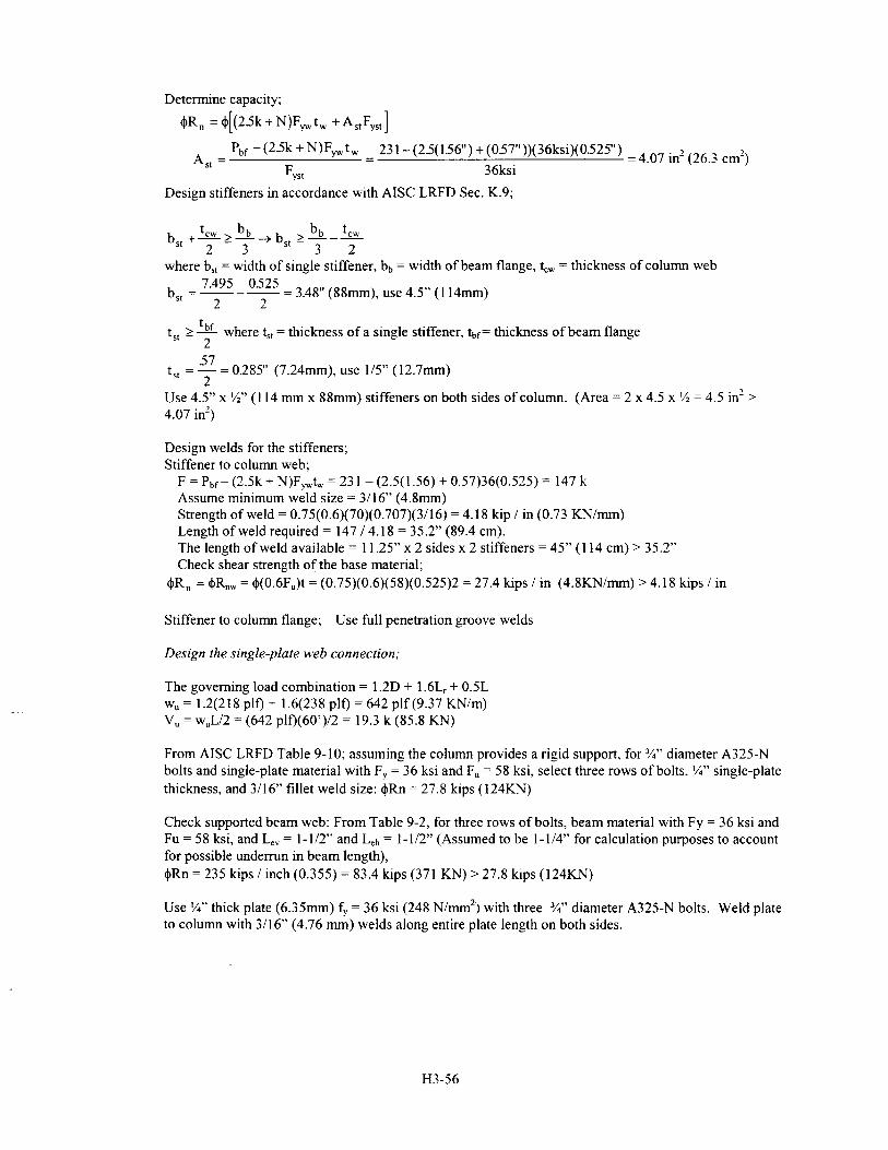
H3-57
Design of horizontal bracing connections:
The design of these connections follows Figure 7-22.Assume plate thickness = ½” (12.7 mm); thickness of brace = 0.337” (8.56mm); E70XX welds
Design of brace-to-gusset weld;
Design weld capacity to be greater than axial capacity of brace = RyFyAg = 1.5(36ksi)(4.41 in.2) = 238 k (1059 KN)Minimum weld size = 3/16” (4.76mm) (AISC LRFD Table J2.4)Maximum weld size = brace thickness – 1/16” = 0.337”-1/16” = 0.28” (7.11mm) (AISC LRFD Sec. J2.b)Use ¼” welds (0.25”) (6.35mm) 3/16<1/4<0.28, OK
Strength of weld; (per AISC LRFD Sec. J.4 and Table J2.5)
Weld material: φRnw = φ(te) (0.6 FEXX) = 0.75(0.6)(70ksi)(0.707)(0.25) = 5.6 kips / inch (0.98 KN/mm) (governs)Base material: φRnw = φ(0.6Fu)t = (0.75)(0.337”)(0.6)(58) = 8.8 kips / in (1.54 KN/mm)
Length of weld required = 238 k / (5.6 k/”) = 43” (109cm) (4 welds at connection, use 11” (27.9 cm) welds, 4 x 11= 44 > 43)
Use 11” (27.9 cm) long ¼” (6.35 mm) fillet welds on all four sides
Check gusset plate capacity
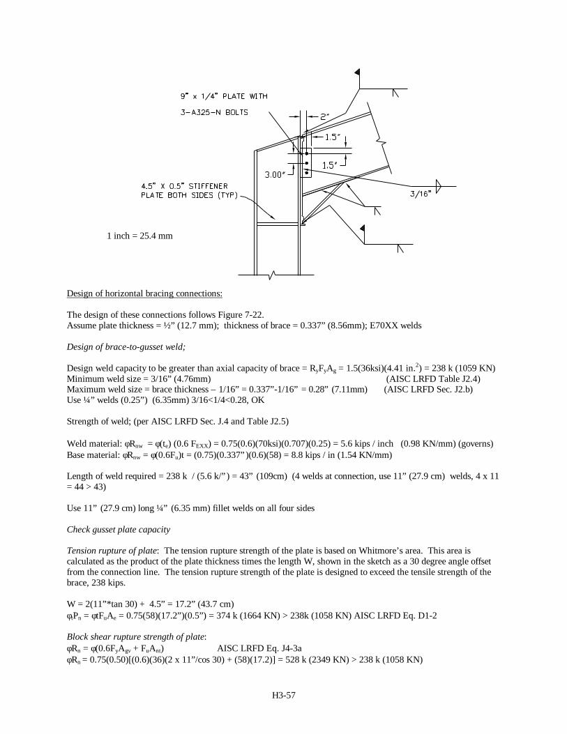
Tension rupture of plate: The tension rupture strength of the plate is based on Whitmore’s area. This area iscalculated as the product of the plate thickness times the length W, shown in the sketch as a 30 degree angle offsetfrom the connection line. The tension rupture strength of the plate is designed to exceed the tensile strength of thebrace, 238 kips.
W = 2(11”*tan 30) + 4.5” = 17.2” (43.7 cm)φtPn = φtFuAe = 0.75(58)(17.2”)(0.5”) = 374 k (1664 KN) > 238k (1058 KN) AISC LRFD Eq. D1-2
Block shear rupture strength of plate:φRn = φ(0.6FyAgv + FuAnt) AISC LRFD Eq. J4-3aφRn = 0.75(0.50)[(0.6)(36)(2 x 11”/cos 30) + (58)(17.2)] = 528 k (2349 KN) > 238 k (1058 KN)
1 inch = 25.4 mm
H3-58
φRn = φ[0.6FuAnv + FyAgt] AISC LRFD Eq. J4-3bφRn = 0.75(0.5) [(0.6)(58)(2 x 11) + (36)(17.2)] = 519 k (2309 KN) > 238 k (1058 KN)
Buckling of plate:
Buckling capacity of the brace = AgFcr = φcPn / φc = 87 kips / 0.85 = 102 kips (454 KN) (buckling strengthdetermined previously)
0 904000
0 904000 1 2 36
12 4102
3 3
. .( / )
.
t f
lkips (457
y
c= = >218 kips (970KN) KN) , OK
Out-of-plane strength of plate: The bracing member can buckle both in and out of plane due to the round sectionused. For out-of-plane buckling the gusset plate must be able to accommodate the rotation by bending. The braceshall terminate on the gusset a minimum of two times the gusset thickness from the theoretical line of bending whichis unrestrained by the column or beam joints. This ensures that the mode of deformation in the plate will be throughplastic hinging rather than torsional fracture.
1 inch = 25.4 mm
H3-59
Design of gusset-to-column flange and beam web weld;
This connection requires a weld length greater than the column flange. The plate must be welded to both the columnflange and the beam web to develop the brace force.Design weld capacity to be greater than horizontal component of brace capacity = (0.707)(238) = 168 kips (747 KN)Column flange thickness = 0.86 in. (21.8mm)Beam web thickness = 0.31”Minimum weld size = ¼” (6.35mm) (AISC LRFD Table J2.4)Maximum weld size = beam web thickness ≈ 0.25” (6.35 mm)Use 1/4” (6.35 mm) welds
Strength of weld; (per AISC LRFD Sec. J.4 and Table J2.5)
Weld material: φRnw = φ(te) (0.6 FEXX) = 0.75(0.6)(70ksi)(0.707)(0.25) = 5.57 kips / inch (0.98 KN/mm) (governs)
Base material: φRnw = φ(0.6Fu) = (0.75)(0.31”)(0.6)(58) = 8.1 kips / in (1.42 KN/mm)
Length of weld required = 168 k / (5.57 k/”) = 30.16” (76.6 cm) (2 welds at connection weld 16” (40.64 cm) long =32” > 30.16”)
Use 1/4” (6.35mm) fillet welds on top and bottom of plate.
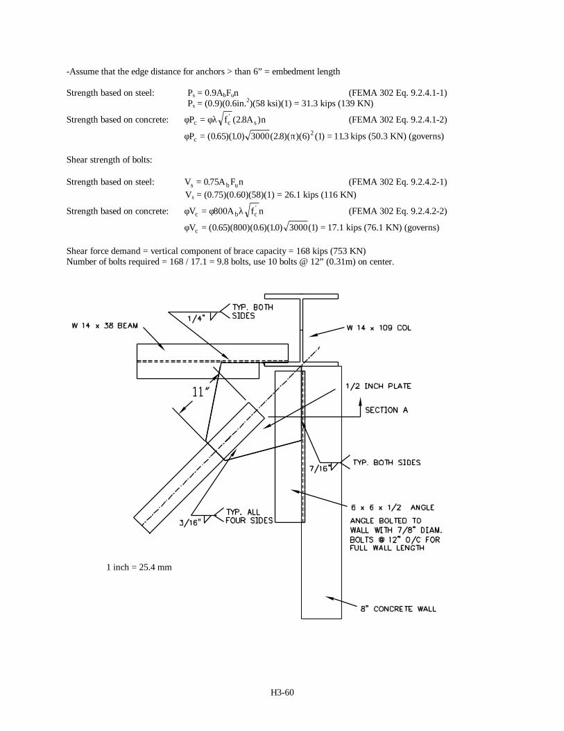
Design member to develop force into shear wall
Vertical component = (0.707)(238k) = 168 kips (747 KN)
Use 6 x 6 x ½ angle to develop forces; Assume 7/8” anchor bolts to concrete shear wall
Check gross section yielding; Pu = φtFyAg = (0.9)(36)(5.75) = 186 kips (827 KN) > 168 kips (747 KN)Check net section fracture; Pu = φtFuAe = (0.75)(58)(0.85)(5.75 – (7/8+1/16)(0.5)) = 195 kips (867 KN) > 168 kips
Design weld of plate to angleMinimum weld size = ¼” (6.35mm) (AISC LRFD Table J2.4)Maximum weld size = plate thickness – 1/16” = 0.5-1/16 = 0.44” (11.18mm)Use 7/16” (11.11 mm) welds (0.438”)
Strength of weld; (per AISC LRFD Sec. J.4 and Table J2.5)
Weld material: φRnw = φ(te) (0.6 FEXX) = 0.75(0.6)(70ksi)(0.707)(0.438) = 9.75 kips / inch (1.71 KN/mm)(governs)
Base material: φRnw = φ(0.6Fu)t = (0.75)(0.5”)(0.6)(58) = 13.05 kips / in (2.29 KN/mm)
Length of weld required = 168 k / (9.75 k/”) = 17.23” (43.8 cm) (2 welds at connection, weld for 16” on both sidesof plate. Total length = 2 x 16 = 32” (81.3 cm) > 17.23” (43.8 cm), OK
Use 16” long (81.3 cm) 7/16” (11.11mm) fillet welds along top and bottom of plate.
Design bolts for angle to wall connection.
Design per FEMA 302
Tensile strength of bolts:
-Assume 7/8” diameter bolts @ 12”o/c with a 6” embedment length
H3-60
-Assume that the edge distance for anchors > than 6” = embedment length
Strength based on steel: Ps = 0.9AbFun (FEMA 302 Eq. 9.2.4.1-1) Ps = (0.9)(0.6in.2)(58 ksi)(1) = 31.3 kips (139 KN)
Strength based on concrete: φ φλP f A nc c s= ' ( . )2 8 (FEMA 302 Eq. 9.2.4.1-2)
φ πPc = =( . )( . ) ( . )( )( ) ( ) .0 65 10 3000 2 8 6 1 1132 kips (50.3 KN) (governs)
Shear strength of bolts:
Strength based on steel: V A F ns b u= 0 75. (FEMA 302 Eq. 9.2.4.2-1) Vs = (0.75)(0.60)(58)(1) = 26.1 kips (116 KN)
Strength based on concrete: φ φ λV A f nc b c= 800 ' (FEMA 302 Eq. 9.2.4.2-2)
φVc = =( . )( )( . )( . ) ( )0 65 800 0 6 10 3000 1 17.1 kips (76.1 KN) (governs)
Shear force demand = vertical component of brace capacity = 168 kips (753 KN)Number of bolts required = 168 / 17.1 = 9.8 bolts, use 10 bolts @ 12” (0.31m) on center.
1 inch = 25.4 mm
H3-61
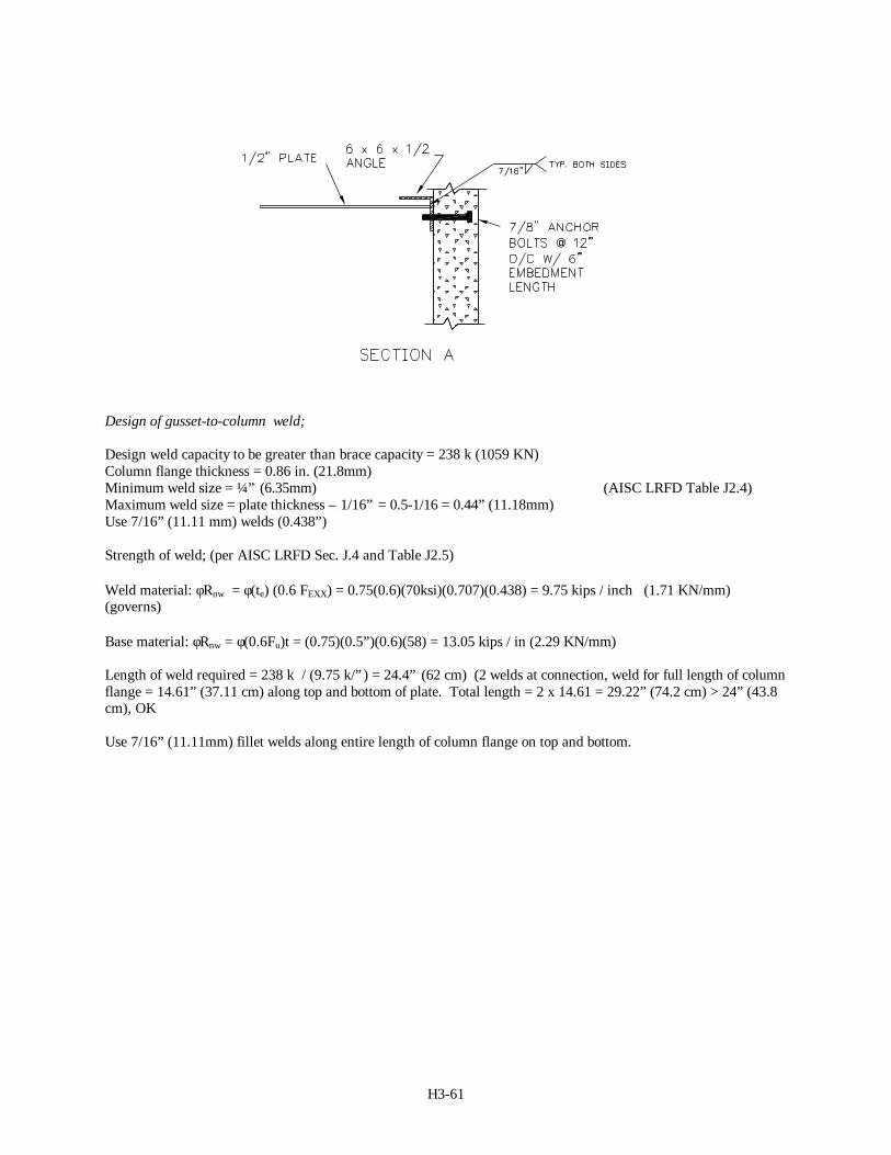
Design of gusset-to-column weld;
Design weld capacity to be greater than brace capacity = 238 k (1059 KN)Column flange thickness = 0.86 in. (21.8mm)Minimum weld size = ¼” (6.35mm) (AISC LRFD Table J2.4)Maximum weld size = plate thickness – 1/16” = 0.5-1/16 = 0.44” (11.18mm)Use 7/16” (11.11 mm) welds (0.438”)
Strength of weld; (per AISC LRFD Sec. J.4 and Table J2.5)
Weld material: φRnw = φ(te) (0.6 FEXX) = 0.75(0.6)(70ksi)(0.707)(0.438) = 9.75 kips / inch (1.71 KN/mm)(governs)
Base material: φRnw = φ(0.6Fu)t = (0.75)(0.5”)(0.6)(58) = 13.05 kips / in (2.29 KN/mm)
Length of weld required = 238 k / (9.75 k/”) = 24.4” (62 cm) (2 welds at connection, weld for full length of columnflange = 14.61” (37.11 cm) along top and bottom of plate. Total length = 2 x 14.61 = 29.22” (74.2 cm) > 24” (43.8cm), OK
Use 7/16” (11.11mm) fillet welds along entire length of column flange on top and bottom.
H3-62
1 inch = 25.4 mm

H3-63