Embed Size (px)
Citation preview
10/21/2015
1
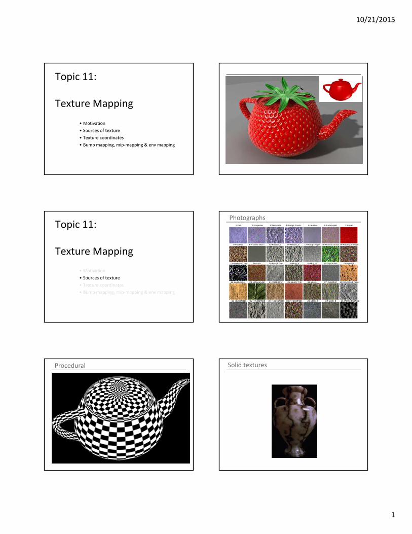
Topic 11:
Texture Mapping
• Motivation
• Sources of texture
• Texture coordinates
• Bump mapping, mip‐mapping & env mapping
Topic 11:
Texture Mapping
• Motivation
• Sources of texture
• Texture coordinates
• Bump mapping, mip‐mapping & env mapping
Photographs
Procedural Solid textures
10/21/2015
2
SynthesizedOriginal Synthesized
Original Synthesized
Topic 11:
Texture Mapping
• Motivation
• Sources of texture
• Texture coordinates
• Bump mapping, mip‐mapping & env mapping
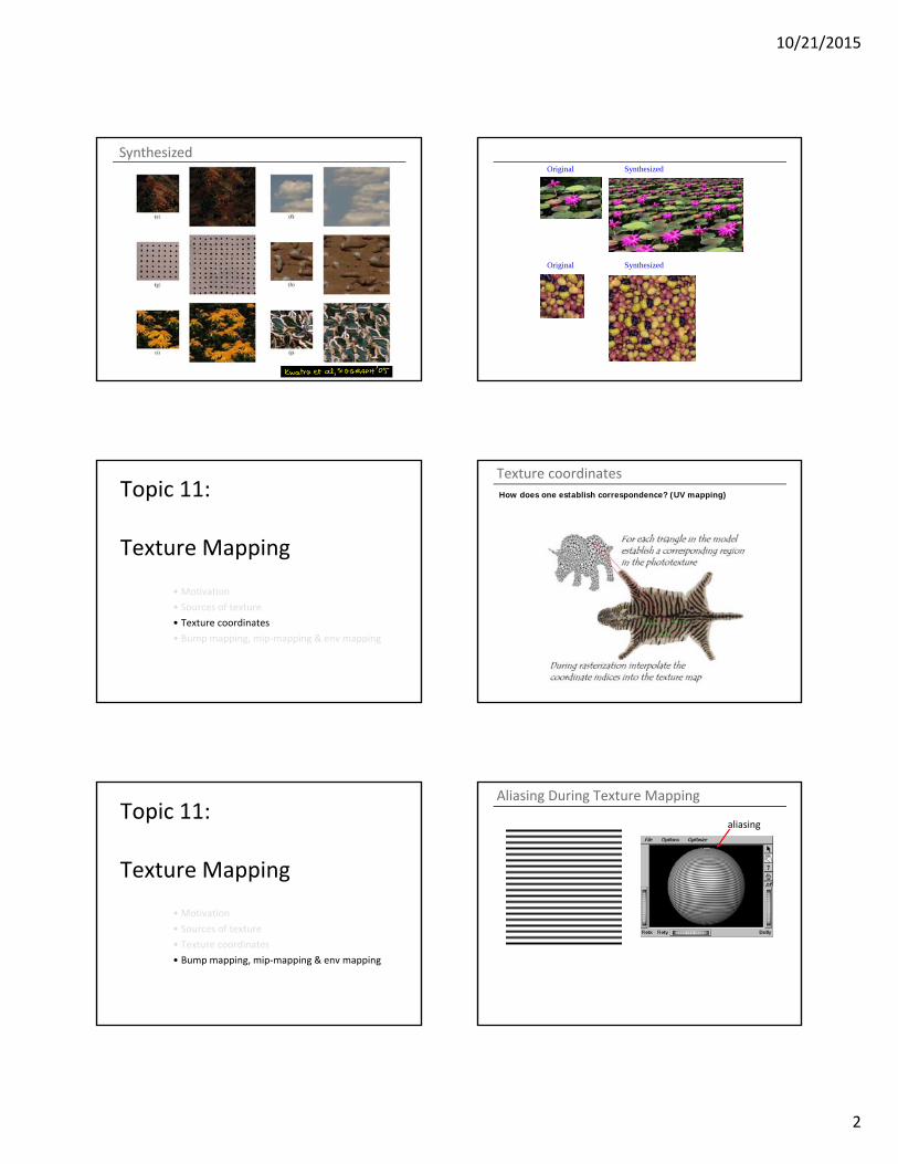
Texture coordinates
How does one establish correspondence? (UV mapping)
Topic 11:
Texture Mapping
• Motivation
• Sources of texture
• Texture coordinates
• Bump mapping, mip‐mapping & env mapping
Aliasing During Texture Mapping
aliasing
10/21/2015
3
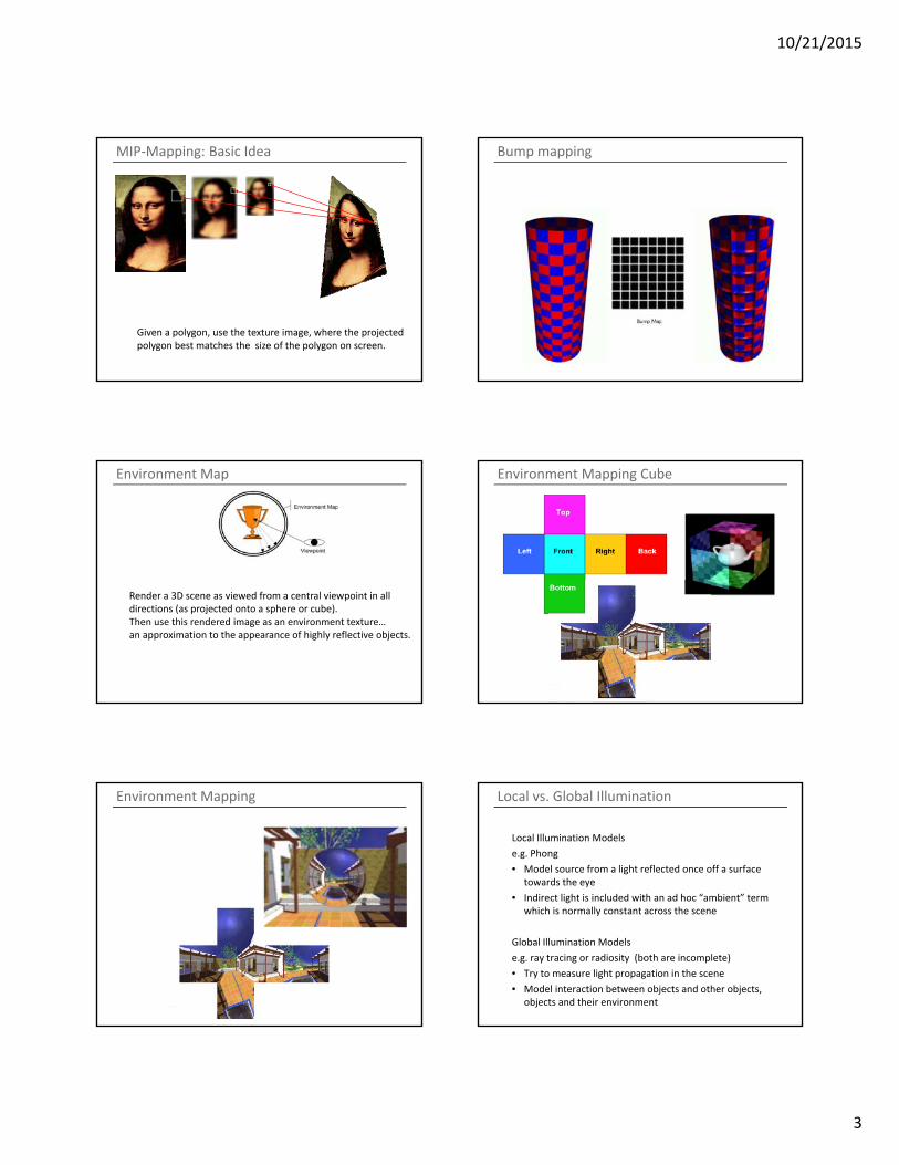
MIP‐Mapping: Basic Idea
Given a polygon, use the texture image, where the projected polygon best matches the size of the polygon on screen.
Bump mapping
Environment Map
Render a 3D scene as viewed from a central viewpoint in alldirections (as projected onto a sphere or cube). Then use this rendered image as an environment texture…an approximation to the appearance of highly reflective objects.
Environment Mapping Cube
Environment Mapping Local vs. Global Illumination
Local Illumination Models
e.g. Phong
• Model source from a light reflected once off a surface towards the eye
• Indirect light is included with an ad hoc “ambient” term which is normally constant across the scene
Global Illumination Models
e.g. ray tracing or radiosity (both are incomplete)
• Try to measure light propagation in the scene
• Model interaction between objects and other objects, objects and their environment
10/21/2015
4
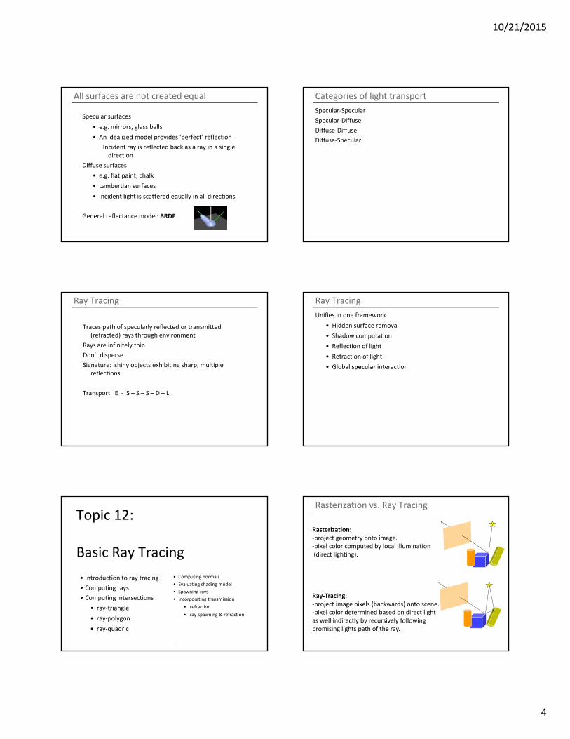
All surfaces are not created equal
Specular surfaces
• e.g. mirrors, glass balls
• An idealized model provides ‘perfect’ reflection
Incident ray is reflected back as a ray in a single direction
Diffuse surfaces
• e.g. flat paint, chalk
• Lambertian surfaces
• Incident light is scattered equally in all directions
General reflectance model: BRDF
Categories of light transport
Specular‐Specular
Specular‐Diffuse
Diffuse‐Diffuse
Diffuse‐Specular
Ray Tracing
Traces path of specularly reflected or transmitted (refracted) rays through environment
Rays are infinitely thin
Don’t disperse
Signature: shiny objects exhibiting sharp, multiple reflections
Transport E ‐ S – S – S – D – L.
Ray Tracing
Unifies in one framework
• Hidden surface removal
• Shadow computation
• Reflection of light
• Refraction of light
• Global specular interaction
Topic 12:
Basic Ray Tracing
• Introduction to ray tracing
• Computing rays
• Computing intersections
• ray‐triangle
• ray‐polygon
• ray‐quadric
• Computing normals
• Evaluating shading model
• Spawning rays
• Incorporating transmission
• refraction
• ray‐spawning & refraction
Rasterization vs. Ray Tracing
Rasterization: ‐project geometry onto image.‐pixel color computed by local illumination(direct lighting).
Ray‐Tracing:‐project image pixels (backwards) onto scene.‐pixel color determined based on direct lightas well indirectly by recursively following promising lights path of the ray.
10/21/2015
5
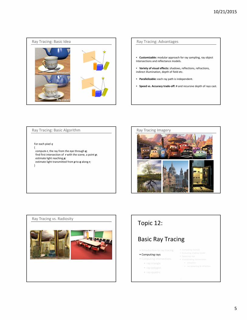
Ray Tracing: Basic Idea Ray Tracing: Advantages
• Customizable:modular approach for ray sampling, ray objectIntersections and reflectance models.
• Variety of visual effects: shadows, reflections, refractions, indirect illumination, depth of field etc.
• Parallelizable: each ray path is independent.
• Speed vs. Accuracy trade‐off: # and recursive depth of rays cast.
Ray Tracing: Basic Algorithm
For each pixel q{compute r, the ray from the eye through q;find first intersection of r with the scene, a point p;estimate light reaching p;estimate light transmitted from p to q along r;}
Ray Tracing Imagery
Ray Tracing vs. RadiosityTopic 12:
Basic Ray Tracing
• Introduction to ray tracing
• Computing rays
• Computing intersections
• ray‐triangle
• ray‐polygon
• ray‐quadric
• Computing normals
• Evaluating shading model
• Spawning rays
• Incorporating transmission
• refraction
• ray‐spawning & refraction
10/21/2015
6
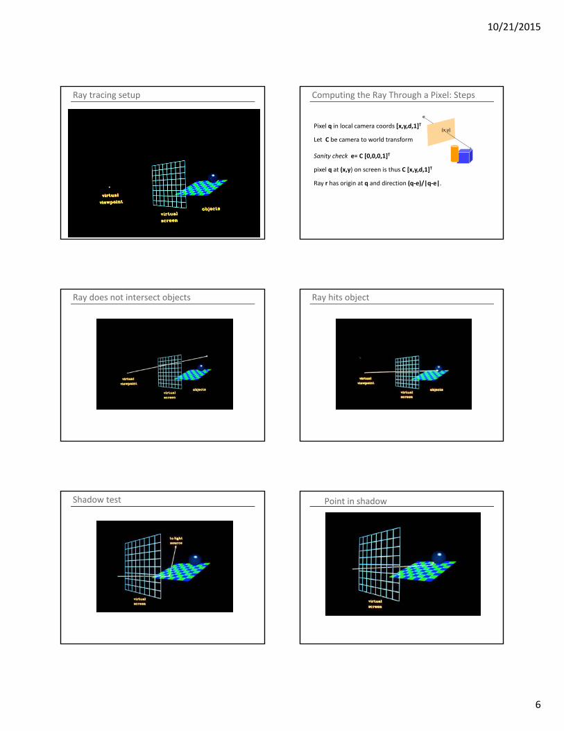
Ray tracing setup Computing the Ray Through a Pixel: Steps
Pixel q in local camera coords [x,y,d,1]T
Let C be camera to world transform
Sanity check e= C [0,0,0,1]T
pixel q at (x,y) on screen is thus C [x,y,d,1]T
Ray r has origin at q and direction (q‐e)/|q‐e|.
(x,y)
e
Ray does not intersect objects Ray hits object
Shadow test Point in shadow
10/21/2015
7
Topic 12:
Basic Ray Tracing
• Introduction to ray tracing
• Computing rays
• Computing intersections
• ray‐triangle
• ray‐polygon
• ray‐quadric
• the scene signature
• Computing normals
• Evaluating shading model
• Spawning rays
• Incorporating transmission
• refraction
• ray‐spawning & refraction
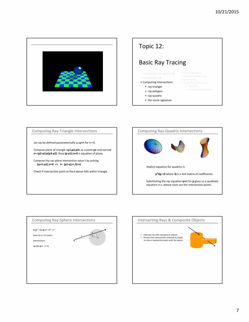
Computing Ray‐Triangle Intersections
Let ray be defined parameterically as q+rt for t>=0.
Compute plane of triangle <p1,p2,p3> as a point p1 and normaln= (p2‐p1)x(p3‐p2). Now (p‐p1).n=0 is equation of plane.
Compute the ray‐plane intersection value t by solving(q+rt‐p1).n=0 => t= (p1‐q).n /(r.n)
Check if intersection point at the t above falls within triangle.
Computing Ray‐Quadric Intersections
Implicit equation for quadrics is
pTQp =0 where Q is a 4x4 matrix of coefficients.
Substituting the ray equation q+rt for p gives us a quadraticequation in t, whose roots are the intersection points.
Computing Ray‐Sphere Intersections
cq
r d
(c‐q)2 –((c‐q).r)2 =d2 ‐ k 2
Solve for k, if it exists.
Intersections:
q+r((c‐q).r +/‐ k)
k
Intersecting Rays & Composite Objects
• Intersect ray with component objects• Process the intersections ordered by depth
to return intersection pairs with the object.
10/21/2015
8
Ray Intersection: Efficiency Considerations
Speed‐up the intersection process.• Ignore object that clearly don’t intersect.• Use proxy geometry.• Subdivide and structure space hierarchically.• Project volume onto image to ignore entireSets of rays.
Topic 12:
Basic Ray Tracing
• Introduction to ray tracing
• Computing rays
• Computing intersections
• ray‐triangle
• ray‐polygon
• ray‐quadric
• the scene signature
• Computing normals
• Evaluating shading model
• Spawning rays
• Incorporating transmission
• refraction
• ray‐spawning & refraction
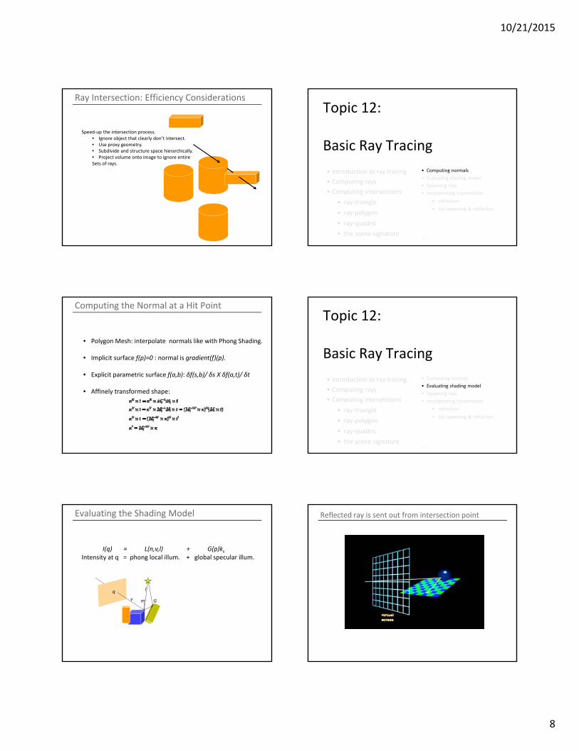
Computing the Normal at a Hit Point
• Polygon Mesh: interpolate normals like with Phong Shading.
• Implicit surface f(p)=0 : normal is gradient(f)(p).
• Explicit parametric surface f(a,b): δf(s,b)/ δs X δf(a,t)/ δt
• Affinely transformed shape:
Topic 12:
Basic Ray Tracing
• Introduction to ray tracing
• Computing rays
• Computing intersections
• ray‐triangle
• ray‐polygon
• ray‐quadric
• the scene signature
• Computing normals
• Evaluating shading model
• Spawning rays
• Incorporating transmission
• refraction
• ray‐spawning & refraction
Evaluating the Shading Model
I(q) = L(n,v,l) + G(p)ksIntensity at q = phong local illum. + global specular illum.
q
v
l
n G
Reflected ray is sent out from intersection point
10/21/2015
9
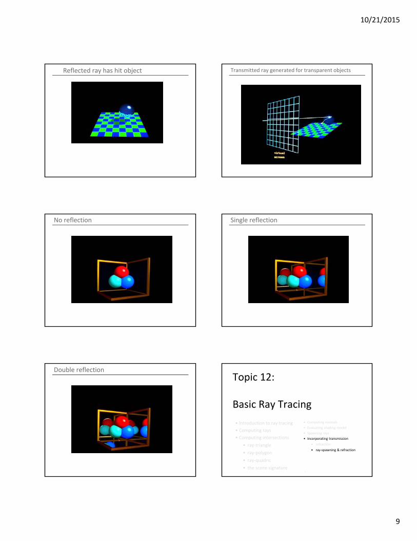
Reflected ray has hit object Transmitted ray generated for transparent objects
No reflection Single reflection
Double reflectionTopic 12:
Basic Ray Tracing
• Introduction to ray tracing
• Computing rays
• Computing intersections
• ray‐triangle
• ray‐polygon
• ray‐quadric
• the scene signature
• Computing normals
• Evaluating shading model
• Spawning rays
• Incorporating transmission
• refraction
• ray‐spawning & refraction
10/21/2015
10
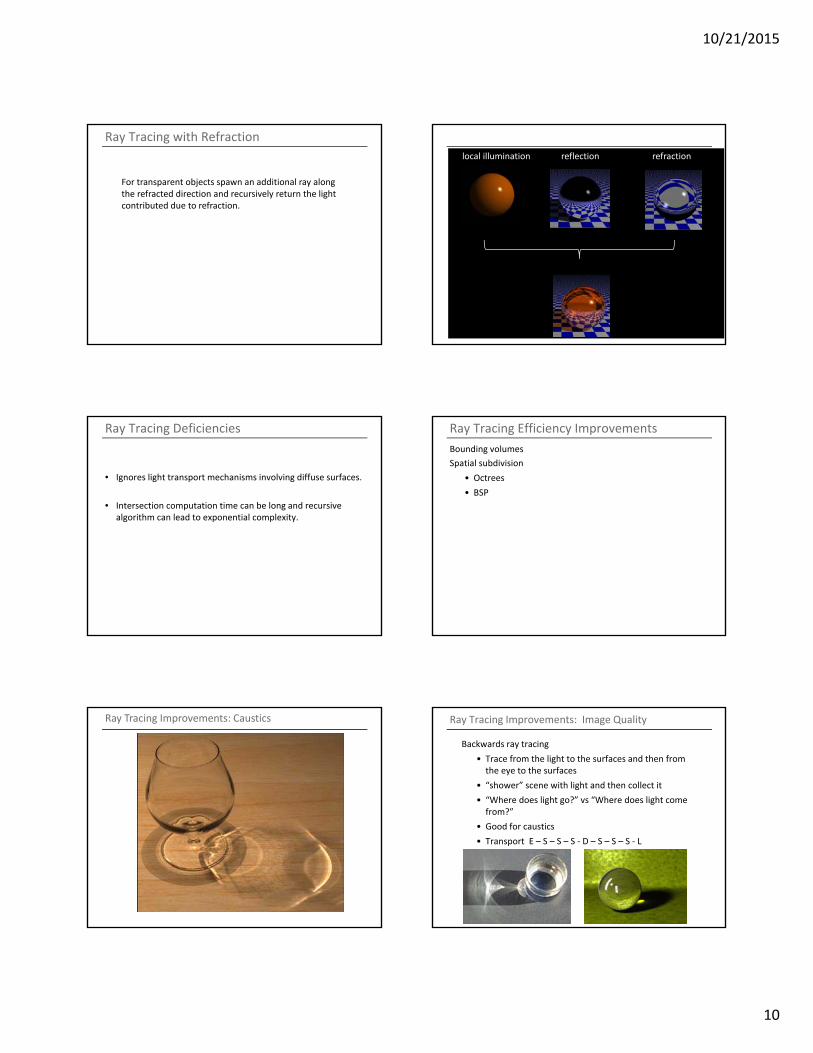
Ray Tracing with Refraction
For transparent objects spawn an additional ray alongthe refracted direction and recursively return the light contributed due to refraction.
local illumination reflection refraction
Ray Tracing Deficiencies
• Ignores light transport mechanisms involving diffuse surfaces.
• Intersection computation time can be long and recursive algorithm can lead to exponential complexity.
Ray Tracing Efficiency Improvements
Bounding volumes
Spatial subdivision
• Octrees
• BSP
Ray Tracing Improvements: Caustics Ray Tracing Improvements: Image Quality
Backwards ray tracing
• Trace from the light to the surfaces and then from the eye to the surfaces
• “shower” scene with light and then collect it
• “Where does light go?” vs “Where does light come from?”
• Good for caustics
• Transport E – S – S – S ‐ D – S – S – S ‐ L
10/21/2015
11
Ray Tracing Improvements: Image Quality
Cone tracing
• Models some dispersion effects
Distributed Ray Tracing
• Super sample each ray
• Blurred reflections, refractions
• Soft shadows
• Depth of field
• Motion blur
Stochastic Ray Tracing
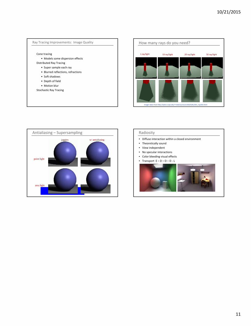
How many rays do you need?
1 ray/light 10 ray/light 20 ray/light 50 ray/light
Images taken from http://web.cs.wpi.edu/~matt/courses/cs563/talks/dist_ray/dist.html
Antialiasing – Supersampling
point light
area light
jaggies w/ antialiasing
Radiosity
• Diffuse interaction within a closed environment
• Theoretically sound
• View independent
• No specular interactions
• Color bleeding visual effects
• Transport E – D – D – D ‐ L