Embed Size (px)
Citation preview
2.04.60 P 1
SEQ VAA REV 00
SPECIAL OPERATIONS
ALL WEATHER OPERATIONS
VI6 MSN ALL
Flight Crew Operating ManualA340-600
INTRODUCTIONAll pilots converting onto the A340 will be trained to Cat 3B limit.
LINE TRAINING
On completion of the Ground School and Simulator Course, which includes a dedicated AWOPS SimulatorSession, First Officers are fully qualified for AWOPS Cat 3B. Captains will complete one Autoland with aTraining Captain, Line Check Captain or Line Training Captain to become fully qualified.Commanders will have to obtain 50 hours or 20 sectors as pilot-in-command on type before performingany category 2 or 3 operation, this requirement will normally be satisfied by the end of Line Training.
NEW CAPTAINS RESTRICTED MINIMAIn addition to these requirements, Commanders with less than 100 hours or 40 sectors as pilot-in-command on type shall add 100 metres to the applicable Category 2/3 RVR minimum. Captains with previous Category 2/3 experience are exempt from this requirement.
REVALIDATIONPilots will revalidate their LVO qualification on each OPC by carrying out a minimum of threeapproaches, one of which must culminate in a missed approach. Additionally one low visibility take-offat the lowest minima must be flown. The individual’s LVO card must be signed.
RECENCYRecency for LVO is maintained by the recurrent training and checking prescribed above. It is desirable thatCaptains perform one autoland every six months on the aircraft and, although this landing will count towardsnormal landing recency, it is not intended that this alleviation would be used on a regular basis. At any timean autoland is carried out the pilots landing record card should be annotated.
In addition to the normal pre-flight planning, the following points must be covered :
WEATHERThe weather at the departure aerodrome must be equal to or greater than the prescribed take-off minima below:
PROCEDURE TRAINING NOTES
FLIGHT PLANNING
VIRGIN ATLANTIC AIRWAYS REVISION 05 / 16 November 2004
2.04.60 P 2
SEQ VAA REV 00
SPECIAL OPERATIONS
ALL WEATHER OPERATIONS
VI6 MSN ALL
Flight Crew Operating ManualA340-600
RVR VISIBILITY FOR TAKE-OFF
Notes: 1. For night operations, at least runway edge and runway end lights are required.2. The reported RVR/visibility representative of the initial part of the take-off run may be replaced
by pilot assessment.3. State take-off minima applies where more restrictive.
If the RVR is reported in segments, the required RVR must be satisfied in all segments. Airfields at whichhigher than normal take-off minima by Company restriction, or runways where take-off is prohibited will benotified in the Captain’s brief.Although the JAA definition of a low visibility T/O is a T/O in a reported RVR of less than 400m, Company LVOprocedures are to be used whenever LVO procedures are in force or the RVR is less than CAT 1.If the weather at the departure aerodrome is below the appropriate landing minima, a take-off alternateaerodrome must be nominated within 120 minutes at one engine out speed, with a MET report/forecast to beat or above Cat 1 from 1 hour before to 1 hour after the aircraft’s ETA.
Planning Minima En-Route and Destination Alternate Airfields
Notes: 1. RVR and ceiling Cat 1 or greater.2. The RVR and ceiling must be at or above the MDA.3. State minima may be at variance with the table above.
Two destination alternates are required if the destination weather is forecast to be below Cat 1 minima from 1hour before to 1 hour after the aircraft’s ETA. State alternate minima, where more restrictive apply.
BRIEFING or AISCheck that there are no NOTAMs applicable for the destination such that a Cat 2 or 3 approach is precluded.
FACILITIES RVR/Visibility (m)Nil (Day Only) 500Runway Edge lighting and/or Centreline Marking 250 (1)Runway Edge lighting and Centreline Lighting 200 Runway Edge centreline lighting with multiple RVR info 125 (2)
Type of Approach at Alternate Planning Minima at ALTCAT II and III Cat I (NOTE 1)Cat I Non-Precision (NOTE 2)Non-Precision Non-Precision plus 200 ft/1000mCircling Circling
VIRGIN ATLANTIC AIRWAYS REVISION 01 / 01 July 2002
2.04.60 P 3
SEQ VAA REV 00
SPECIAL OPERATIONS
ALL WEATHER OPERATIONS
VI6 MSN ALL
Flight Crew Operating ManualA340-600
CREW
Qualified for conditions :In order to operate below Cat 1, all crew must be in possession of a current Low Visibility Operations Rating/Revalidation Card.
FUEL
Careful consideration must be given to fuel requirements. Additional fuel will almost certainly be required forthe following reasons :1. Approach delays caused by increased separation between aircraft on Approach, probably involving low
altitude holding and longer than normal approach routings.2. Delays caused by a backlog of departing and arriving traffic.3. Increments for anti-icing and manoeuvring.4. Potential diversion delays and holding at the nominated diversion airfield.It must be appreciated that there are a large number of aircraft equipped to operate in Cat 2 and 3 conditions,and that the ability to so operate will not necessarily guarantee priority approach clearance.For these reasons, an additional amount equal to at least 45 minutes holding fuel at destination shouldnormally be carried, and extra taxi fuel should be considered when planning a take-off in LVO conditions.
In addition to the normal checks :Check autopilot is not downgraded in the Tech Log. Autoland status is limited to the ADD declared status untilthe ADD is cleared.Ensure that the aircraft has no other defects that would affect approach capability, which can be confirmedusing the Required Equipment for Cat 2 and Cat 3 Table.Check familiarity with the Cat 2/3 holding points for the take-off and any taxiways which should or should notbe used. Within Europe if flow restrictions are in force due to destination weather conditions, prior to start-upinform ATC of the intention of Cat 2/3 landing at destination.
AT THE AIRCRAFT
VIRGIN ATLANTIC AIRWAYS REVISION 01 / 01 July 2002
2.04.60 P 4
SEQ VAA REV 00
SPECIAL OPERATIONS
ALL WEATHER OPERATIONS
VI6 MSN ALL
Flight Crew Operating ManualA340-600
Bear in mind that in poor visibility, e.g. 100m (330 ft) RVR, one might expect to see bright lights 100m away,but not unlit or poorly lit obstacles such as aircraft tails or wingtips. From certain angles their navigation lightsare not readily discernible and the greatest distance from which a white painted aircraft may be visible in 100mRVR may be less than 75m. Movement rates will be low in these conditions, but taxi as slowly as safetydemands.Use of Ground Movement radar, the compass, aerodrome chart and the low visibility ground movementchart will help to assess the aircraft position and help in anticipating bends in the taxiways. Centrelinelight spacing may be reduced on bends and caution should be exercised when coming out of the bendwhere the lighting reverts to normal. Be careful not to pass the Cat 2/3 holding point : green taxiwaycentre-line lights may be illuminated beyond the Cat 2/3 holding point if it does not coincide with ataxiway stopbar or if a preceding aircraft is just lining up.The First Officer should monitor the groundspeed display, advising the Captain of excessive speed andgenerally keep a look out for other aircraft as well as assisting the Captain by reference to the taxy charts whenrequired. No checks should be carried out until the aircraft is at the holding point for the runway in useand, in particular, until the Cat 2/3 holding point has been identified and complied with. The JeppesenCharts show the minimum RVR for takeoff for the intended runway. All relevant RVR's must be at or abovethe minimum listed.Prior to entering the runway, consider the runway state and braking action especially with a RVR of 125 m.Check the appropriate RVRs are above minima before passing the holding point.As the aircraft is lined up on the runway, confirm that it is placed on the runway centreline lights and not theedge lights. Use of the ILS for that runway can be of assistance. Check that the number of visible centre-linelights is consistent with the reported RVR. The minimum number should be 9 or 5 for a spacing of 15 m or30 m respectively for a RVR of 125 m.
The main aid during the take-off run will be the centreline lighting. Care should be taken not to confusethe centreline lighting with runway edge lighting. Prior to brake release check aircraft heading is thesame as the expected runway direction.If available, the departure runway ILS will be autotuned and LS pushbuttons must be ON for take-off.RWY mode will engage upon application of take-off thrust providing runway centreline guidance.Although useful as a centreline indication, they should not be used as a sole reference during take-off.TOGA thrust should be used to minimise the ground roll and it should be noted that the maximumcrosswind allowed for take-off in these conditions is 10 kts.Should there be any significant deviation left or right of the runway centreline, the First Officer will call“deviating left” or “deviating right” as appropriate.During the take-off the Captain may need to direct his attention inside (for example when entering a fogbank), and should announce this by calling “HEADS IN”. The First Officer will then direct his attentionoutside and call “HEADS OUT”. The Captain will keep control of the Aircraft and monitor that the Aircraftis tracking along the runway centreline by using localiser guidance on the PFD/ND. When the FirstOfficer regains visual reference he calls “HEADS IN”. The Captain then looks out and responds “HEADSOUT”.
TAXI OUT
TAKEOFF
VIRGIN ATLANTIC AIRWAYS REVISION 01 / 01 July 2002
2.04.60 P 5
SEQ VAA REV 00
SPECIAL OPERATIONS
ALL WEATHER OPERATIONS
VI6 MSN ALL
Flight Crew Operating ManualA340-600
Standard abandon drills must be used, bearing in mind the following:The green “DECEL” indication on the autobrake should be monitored carefully to ensure correct systemoperation.As speed reduces the centreline lights become increasingly difficult to follow in low visibility. TheCaptain should concentrate his attention outside whilst the First Officer glances at the PFD indications,advising the Captain when appropriate.On a standard Cat 2/3 runway, the centreline lighting changes from white to alternating red/white 900mfrom the end and to red for the final 300 m. It should be noted that the use of all external lights (includingstrobes) may aid the emergency services in finding the aircraft.
The key to successful operations in poor weather is careful and timely preparation. Collection of weatherreports and ATIS broadcasts is essential to maintain all diversion options.When within the airways sector containing the airfield of intended landing, ATC should be informed ofthe intended Cat 2/3 approach. This ensures early notice of any change of airfield state and enables ATCto apply those procedures normally established to give priority to Cat 2/3 aircraft.It may be assumed in the UK that when Low Visibility Procedures are promulgated as being in use, theabsence of information to the contrary indicates that all relevant equipment is serviceable. In the UKLVPs will be initiated by ATC when RVR falls below 600 m or cloud base lowers below 200 ft.The approach briefing should be carried out in good time and in a thorough and unhurried mannerensuring that the following items in particular are briefed in addition to those normally required :1. Consideration should be given to switching off the white strobes and landing lights (reducing glare).2. Seat position.3. Call-outs during approach and PNF duties (i.e. remaining on instruments).4. Visual reference required at DH (if applicable) to continue autoland.5. Use of autobrake and flap.6. Procedures for roll out and runway clearance.7. Go around procedure.8. Non-normal and emergency procedures.The appropriate DH for Cat 2/3 is entered into the FMGC. If there is no DH, ‘0’ must still be entered inthe DH box on the Perf Page (produces the “100 above call”).Autobrake should normally be selected to Low but Med can be used if runway length or surfaceconditions warrant it. The selection can be changed during the landing roll if necessary, but no attemptshould be made to exit the runway other than at the specifically illuminated turn off points.
REJECTED TAKE-OFF
EN-ROUTE
VIRGIN ATLANTIC AIRWAYS REVISION 06 / 13 May 2005
2.04.60 P 6
SEQ VAA REV 00
SPECIAL OPERATIONS
ALL WEATHER OPERATIONS
VI6 MSN ALL
Flight Crew Operating ManualA340-600
In addition to the normal checks :
CREW
Qualified and briefing completed.
AIRFIELDEnsure that the runway approved for Cat 2/3 using the Approved Autoland Runways status list andextract minima from Jeppesen charts. Note that only type specific minima must be used and that Cat3B operations are not to be planned on L status runways. Confirm the airfield is operating Cat 2/3 (ATISor RT). Generally, if ATIS and ATC do not report to the contrary, all the necessary facilities areserviceable. If “Low visibility procedures in force” is transmitted, the appropriate runway and ILSprotection procedures are active. The touchdown RVR must be at or above MINIMA. For Cat 2/3, the midpoint RVR need not be reported, butif it is, then it must not be below 150 m, except where the RVR minima is less than 150 m, in which case itmust not be less than 75 m. Rollout RVR is advisory only.Approaching destination, advise ATC that a Cat 2/3 approach will be made, thus ensuring priority over non-Cat 2/3 holding aircraft. When the RVR is just below minimum, and it is necessary to make a decision whetherto remain in the hold for an improvement or to divert, bear in mind that the Volmet and ATIS RVRs may not bethe same as the current RVR. If workload permits, monitoring Tower frequency will give the latest.
AIRCRAFTIf any aircraft equipment is unserviceable (shown in either the Tech Log or on the status page) then prior tothe approach, the landing capability (if not specifically stated in the Tech Log) may be confirmed using theRequired Equipment for Cat 2 and Cat 3 Table. However once the approach has been armed (APPR pbpressed) the landing capability shown on the PFDs should be used for the remainder of the approach.
BEFORE COMMENCING AN APPROACH
VIRGIN ATLANTIC AIRWAYS REVISION 01 / 01 July 2002
2.04.60 P 7
SEQ VAA REV 00
SPECIAL OPERATIONS
ALL WEATHER OPERATIONS
VI6 MSN ALL
Flight Crew Operating ManualA340-600
Full flap is the normal setting for autoland for the following reasons :
1. Lowers the pitch angle thus bringing the lower limit of the visual segment nearer to the aircraft byreducing the coaming cutoff angle, and thereby enabling the PF to obtain visual reference earlier on theapproach.
2. Approach and landing speed is reduced, and the landing distance is also reduced.Prior to initial descent and at approximately 15nm finals carry out a NAV accuracy check.If the check is positive, the ND can be set at ARC or ROSE NAV. If the check is negative, set the ND toROSE LS and do not use NAV mode.On first contact with approach control request a Cat 2/3 approach. When cleared for the approach,press the APPR pb on the FCU and check that LOC and G/S blue is annunciated on the FMA. Engagethe second autopilot. The second autopilot is required for Cat 3 dual approaches and, although onlyone autopilot is required for Cat 2 and Cat 3 single approaches, it is recommended that both autopilotsare engaged systematically.A check should be made that the category indicated on the FMA is sufficient to complete a landing inthe prevailing weather conditions.If the touchdown or midpoint RVR falls below minimum prior to the OM or equivalent position, it ispermissible to continue the approach to the OM or equivalent position, but the approach must bediscontinued by that point if the RVR is still below minimum. If the touchdown RVR is not available, themidpoint RVR may be used in its place.
COMMENCING THE APPROACH
VIRGIN ATLANTIC AIRWAYS REVISION 05 / 16 November 2004
2.04.60 P 8
SEQ VAA REV 00
SPECIAL OPERATIONS
ALL WEATHER OPERATIONS
VI6 MSN ALL
Flight Crew Operating ManualA340-600
Again, on first contact with the Tower, advise that the aircraft is making a Cat 2/3 approach.When the visibility is rapidly improving, the low visibility safeguarding procedures may be abandoned in orderto increase the traffic flow. If this should occur after the aircraft has left the hold, the call to the Tower will enablethe controller to advise that appropriate protection is no longer available.
RVR DETERIORATIONThe RVRs to be borne in mind during the approach are those last reported by the OM or equivalent position.RVR information received after passing the OM or equivalent position is for information only. Deterioration inthe RVRs after passing the OM or equivalent position does not mean an immediate G/A : the approach maycontinue to DH. Descent below DH is solely dependent on obtaining the required visual reference.
1500 ft AALThe aircraft should be stabilized in the landing configuration by 1500ft AAL. After any speed control, the speedmust be MANAGED thus ensuring G/S - mini protection throughout the approach and G/A phases.
1000 ft AALAll call outs below 1000ft during Cat 2/3 approaches are Radio Altitudes. It is very important to observe thestandard call outs and responses. The additional calls specific to an automatic approach and landing areincluded below.
700 ft RAThe ILS frequency and course are frozen in the receiver. Any attempt to change the ILS frequency or coursethrough either the MCDU or RMP will have no effect. Also if the speed is managed, the FMGS will not acceptany modification of information on the PERF APPR page.
500 ft RAPNF calls “500 FEET RADIO”PF replies “CHECK”.
350 ft RALand mode engages automatically when the LOC and G/S modes are engaged and the aircraft is below 400ftAGL. The FMA displays “LAND” indicating that LAND mode has engaged.PF and PNF checks the ILS course on the PFD.PNF calls “LAND GREEN”PF calls “COURSE CHECKED”No action on the FCU will disengage LAND (it can only be disengaged by moving the thrust levers to TOGAand so engaging go-around mode, or after landing). FLARE and ROLLOUT modes will successively engage.
DECISION HEIGHT + 100 ftPNF calls – “HUNDRED ABOVE”(duplicated by auto call).PF replies “CHECK” and if not already visual seeks required visual references.
FINAL APPROACH
VIRGIN ATLANTIC AIRWAYS REVISION 01 / 01 July 2002
2.04.60 P 9
SEQ VAA REV 00
SPECIAL OPERATIONS
ALL WEATHER OPERATIONS
VI6 MSN ALL
Flight Crew Operating ManualA340-600
DECISION HEIGHT (IF APPLICABLE)
PNF calls – “MINIMUMS” (duplicated by auto call).If PF has required visual reference calls “LANDING”.If not PF initiates a G/A by applying TOGA (simultaneously rotating) and then calling “GO-AROUND FLAP”.
40 ft RA
Once the aircraft reaches approximately 40ft RA (the precise value is a function of V/S), FLARE modeengages. The FMA displays “FLARE” in green. If this is not annunciated the PNF calls “NO FLARE”. Onhearing “NO FLARE”, the PF will either complete the landing manually or initiate a go-around.
30 ft RA
The AP/FD aligns the yaw axis with the runway centreline, and the aircraft flares on the pitch axis. If autothrustis active, thrust reduction (RETARD) is activated. The A/THR initiates a thrust reduction towards idle. PNFchecks THR IDLE annunciated on FMA.
10 ft RA
Auto call “RETARD”. PF reduces the throttles to idle and the autothrottle disconnects. PNF monitors engineparameters.
REQUIRED VISUAL REFERENCESCategory II approaches - A pilot may not continue an approach below the decision height unless avisual reference containing a segment of at least 3 consecutive lights being centreline of the approachlights, or touchdown zone lights, or runway centreline lights, or runway edge lights, or a combination ofthese is attained and can be maintained. This visual reference must include a lateral element of theground pattern, i.e an approach lighting crossbar or the landing threshold or a barette of the touchdownzone lighting.Category IIIA approaches - A pilot may not continue an approach below the decision height unless avisual reference containing a segment of at least 3 consecutive lights being centreline of the approachlights, or touchdown zone lights, or runway centreline lights, or runway edge lights, or a combination ofthese is attained and can be maintained. Category IIIB approaches with a decision height - A pilot may not continue an approach below thedecision height unless a visual reference containing a segment of at least one centreline light is attainedand can be maintained.Category IIIB approaches with no decision height - There is no requirement for visual contact withthe runway prior to touchdown.
VIRGIN ATLANTIC AIRWAYS REVISION 01 / 01 July 2002
2.04.60 P 10
SEQ VAA REV 00
SPECIAL OPERATIONS
ALL WEATHER OPERATIONS
VI6 MSN ALL
Flight Crew Operating ManualA340-600
The maximum available automatic capability must be used, and an automatic approach and landing isto be planned and accomplished for all Cat 2 and Cat 3 approaches. Only in very exceptionalcircumstances, as in the non-normal section below, is a manual landing permitted.At touchdown, the PNF checks that “ROLLOUT” is annunciated on FMA calling “ROLLOUT” and that theyaw bar comes up on the PFD. The PNF continues monitoring inside and makes the normal call outs –“SPOILERS”, “REVERSE GREEN”, “DECEL” and the speed calls.The PF will monitor lateral guidance by external reference and select and control reverse thrust.On a standard Cat 2/3 runway, the centreline lighting changes from white to alternating red/white 900 mfrom the end and to red for the final 300 m. At the end of the landing roll disengage the autopilots. (Theautopilots will disengage automatically when the aircraft track differs by more than 20 ft from the LOCaxis).Note: For ILS Cat 3B No DH operations, establish visual reference after nosewheel contact.
Apply reverse thrust as required. When landing on a status (R) runway, leave the autopilot engaged untilthe Captain is ready to turn off the runway. The autopilots maintain the localiser centre-line through therudder and nosewheel steering. The rollout control and autobrakes may remain engaged until a full stopif required.In Cat 2 or 3 conditions, on a (L) Category runway disengage the autopilot after nosewheel touchdownas rollout guidance is not assured. In Cat 1 conditions, the autopilot may remain engaged to evaluaterollout guidance.Should there be any significant deviation left or right of the runway centreline, the PNF will call “deviatingleft” or “deviating right” as appropriate.
Only the normal turn-off and subsequent exit lights will be illuminated during Cat 3 Operations. Do notreport “runway vacated” until the whole of the aircraft is outside the sensitive area shown on theJeppesen charts. It is important that the crew are fully aware of the runway exit point they have used asit will provide a reference point for the taxi in routing and reduce the possibility of getting lost on thetaxiways. If at any time the crew become uncertain of their position on the airfield they must inform ATCimmediately.
The GO-AROUND phase and modes are engaged by setting the thrust levers to TOGA position(provided at least CONFIG 1 is selected).Should a go-around be necessary, the PF calls “GO-AROUND FLAP” and monitors the flight path andFMA. The PNF retracts the flap one step and monitors the engine parameters. The PF calls out the FMAindications i.e. MAN TOGA-SRS-GA-TRK. The aircraft pitches up to maintain SRS speed (the lower ofVAPP or current speed).
LANDING
TAXI IN
GO-AROUND
VIRGIN ATLANTIC AIRWAYS REVISION 01 / 01 July 2002
2.04.60 P 11
SEQ VAA REV 00
SPECIAL OPERATIONS
ALL WEATHER OPERATIONS
VI6 MSN ALL
Flight Crew Operating ManualA340-600
The PNF calls “POSITIVE CLIMB” and selects the landing gear up on the PF's command. NAV or HDGcan now be selected according to ATC clearance. (When another lateral or vertical mode is engaged,No.2 AP will disengage).At the GA thrust reduction altitude, the PF sets the thrust levers to the CL detent.At the GA acceleration altitude, monitor that target speed goes to green dot and clean up on schedule.
The Company philosophy regarding the duties to be performed by each pilot during automaticapproaches will be as follows :1. The Captain will be PF (in less than Cat 1) and will control the aircraft using autopilot and autothrottle.
He will monitor his flight instruments until the “100 above” call at which point he will look outside toassess the visual cues available, making a continuous assessment of his visual reference so that atthe “MINIMUM” call, he can immediately respond by calling “LANDING “ or “G/A Flap”.
2. The PNF will monitor his flight instruments throughout the approach and landing/go-around makingthe appropriate calls. At no time will he attempt to seek visual reference. He will make the appropriatecall if the parameters below are exceeded.a) During GLIDE beam capture :
“PITCH” : lower than 2.5° or greater than 10°.“Vertical Speed” : exceeds 500 ft/min climb or 1250 ft/min descent.
b) During final approach :“SPEED” : lower than VAPP −5 kt or greater than VAPP + 10 kt.“PITCH” : attitude lower than 0° or greater than 10°.“BANK”. : bank angle greater than 7°.“SINK RATE”. : descent greater than 1000 ft/min.“LOC” or “GLIDE”. : excessive LOC or glideslope deviation.
b) During go-around :“BANK” : bank angle greater than 7°.“PITCH”. : attitude greater than 20° or less than 10°.“SINK RATE”. : if there is no climb rate.
3. It should be noticed that these procedures are at variance with those used on non Cat 2/3 approachesin that the normal procedure is for the PNF to seek visual reference prior to decision altitude, reportingto the PF what he can see with the PF looking up at DA and making his assessments. In Cat 2/3conditions this leaves insufficient time to make a proper assessment, since the cues are often quitedifficult to see and require a continuous rather than instantaneous assessment.
4. To avoid confusion, the Cat 2/3 procedures described above will be used for all autoland approaches,whether Cat 1, 2 or 3, whereas for all approaches, automatic or manual, culminating in manuallandings, standard non-LVO procedures will be used. In conditions of Cat 1 or better either pilot mayact as PF. The Cat 1 minima should be entered in the MDA box on the performance page and not inthe DH box.
PILOT DUTIES ON APPROACH
VIRGIN ATLANTIC AIRWAYS REVISION 05 / 16 November 2004
2.04.60 P 12
SEQ VAA REV 00
SPECIAL OPERATIONS
ALL WEATHER OPERATIONS
VI6 MSN ALL
Flight Crew Operating ManualA340-600
Refer to QRH Page 5.04 for checking the Landing Capability should any aircraft equipment beunserviceable prior to making an approach. During the approach, Landing Capability is shown on bothPFDs.
REQUIRED EQUIPMENT FOR CAT 2 AND CAT 3
VIRGIN ATLANTIC AIRWAYS REVISION 05 / 16 November 2004
2.04.60 P 13
SEQ VAA REV 00
SPECIAL OPERATIONS
ALL WEATHER OPERATIONS
VI6 MSN ALL
Flight Crew Operating ManualA340-600
GENERALDuring the approach the PNF should carefully monitor the flight instruments and call any deviationsdefined in the previous section. The PNF should also monitor the FMA calling any changes in the normalway. Any abnormal indications should be announced and for multiple warnings the most limiting courseof action should be applied. If any doubt exists, a G/A may be the safest course of action.
FMA LANDING CAPABILITY AND ANNUNCIATIONSPrior to making an approach if any aircraft equipment is unserviceable the landing capability may beconfirmed using the Required Equipment For Cat 2 and Cat 3 Table. (For unserviceable groundequipment see Failed or Downgraded Ground Equipment Table).Once the APPR pb is pressed the second autopilot should be selected and the FMA checked for LOCand G/S blue and the Landing Capability and autopilot status confirmed. The Landing Capability shownon the FMA should be used as the reference throughout the remainder of the approach.The highest possible capability and therefore lowest minima should be used when available to ensurethe best chance of a successful autoland. Without failures this will mean using a CAT 3 DUAL approachwhich has the advantage of being a fail operational system.An automatic landing system is fail-operational if, in the event of a failure below alert height, theremaining part of the automatic system allows the aircraft to complete the approach, flare, and landing.Alert Height on the A340 is 200 feet RA.Both CAT 3 SINGLE and CAT 2 are fail-passive systems. This means that, in the event of a failure, thereis no significant out-of-trim condition or deviation of flight path or attitude, but the landing is notcompleted automatically.Any downgrade of capability will be accompanied by three clicks and should be announced. Down to1,000 feet AAL the DH for the new capability may be entered into the MCDU. Although if the downgradeoccurs prior to the approach ban position the approach may not be continued past this point unless theRVRs are at or above that required for the new capability. Between 1,000 feet AAL and 200 feet RAwith any downgrade a G/A should be initiated. Below 200 feet RA the FMGS freezes the landingcapability until LAND mode is disengaged or both autopilots are off.If both LOC and G/S modes are engaged and the aircraft is below 400 feet RA, LAND mode will engageautomatically. The FMA will display LAND and this should be called by the PNF. If LAND mode has notengaged by 350 feet RA the PNF should call “NO LAND GREEN” which should prompt a G/A. The ILS course should also be checked by 350 feet RA and if the displayed course is not correct thenagain a G/A should be initiated.If FLARE is not annunciated on the FMA by 30 feet RA the PNF should call “NO FLARE” . On hearingthis call the PF should G/A except where the aircraft has already landed.
NON-NORMALS
VIRGIN ATLANTIC AIRWAYS REVISION 01 / 01 July 2002
2.04.60 P 14
SEQ VAA REV 00
SPECIAL OPERATIONS
ALL WEATHER OPERATIONS
VI6 MSN ALL
Flight Crew Operating ManualA340-600
FAILURE INDICATIONS - GENERALThere are three priority levels for warnings and cautions:Level 1 = Amber caution without aural warning: Requires crew monitoring.Level 2 = Amber caution with single chime: The flight crew should be aware of the configuration or
failure, but need not take immediate action.Level 3 = Red warning plus continuous repetitive chime or specific sound or synthetic voice: Aircraft
in dangerous configuration or limit flight conditions.Anything more than a Level 1 warning, i.e. levels 2 & 3, therefore will require crew action and so in theevent of such a failure or failures occurring during the approach the following procedure should beadopted:Go around unless the appropriate drill can be adequately reviewed and completed prior to reaching1,000 feet AAL. Except for illumination of the red autoland light, when below 200 feet RA, the approach may be continuedbearing mind that for certain failures the autopilot may have to be disconnected for the roll out phase.Level 3 warnings require immediate action and should be dealt with on an individual basis according tothe circumstances.
SPECIFIC FAILURE INDICATIONSAUTOLAND WARNING
With “LAND” or “FLARE” in green on the FMA and at least one AP engaged, the AUTOLAND red lightappears on the glareshield when the aircraft is below 200 feet RA and one of the following events occurs:—The autopilots are lost, or—The aircraft gets too far off the beam (LOC and G/S flash on PFD) or —Loss of LOC signal above 15 feet or loss of glide signal above 100 feet (transmitter or receivers), or—The difference between both radio altimeter indications is greater than 15 feet.AUTOLAND warning flashes for 3 seconds when the AP is manually disconnected (instinctivedisconnect pushbutton) below 200 feet.
ILSWarning of excessive beam deviation
This warning is a flashing of the LOC and G/S scales on the PFD and ND ROSE ILS. It occurs whenever:—G/S deviation is greater than 1 dot (above 100 feet RA)—LOC deviation is greater than 1/4 dot (above 15 feet RA).
Failure of one localizer and glide slope receiverThe respective PFD and ND (rose ILS mode) display red LOC and G/S flags (if the LS pushbutton hasbeen pressed green). LOC and G/S scales disappear from respective PFD. ECAM warning NAV ILS 1(2) FAULT with associated master caution and chime.
VIRGIN ATLANTIC AIRWAYS REVISION 01 / 01 July 2002
2.04.60 P 15
SEQ VAA REV 00
SPECIAL OPERATIONS
ALL WEATHER OPERATIONS
VI6 MSN ALL
Flight Crew Operating ManualA340-600
Failure of both localiser and glideslope receiversBoth PFD and ND (rose ILS mode) display red LOC and G/S flags (if the LS pushbutton has beenpressed green). LOC and G/S scales disappear from the PFD.ECAM warning NAV ILS 1+2 FAULT with associated master caution and chime.If LOC or G/S modes are engaged and at least one AP/FD is engaged:
– The AP disengages.– The FD reverts to its HDG - V/S or TRK - FPA modes.Lower GS Antenna
The glideslope signal is provided via two glideslope antennas, one situated in the radome and the otheron the nose landing gear. During approach, the ILS initially takes the glideslope signal from the radomeantenna and afterwards from the nose landing gear antenna. The switching between both antennas isautomatically performed when the aircraft is below 700ft AGL and the landing gear is locked down. Incase of a “NAV GS 1(2) ON LOWER ANTENNA” ECAM above 700ft the FMGS will consider thismessage as an ILS failure, resulting in a downgrade to Cat 1 only. Should the other possible failure“NAV LOWER GS ANT FAULT” occur, there will be no downgrade as this fault can only be detectedbelow 700ft and is inhibited until below 80kts on the landing roll. This failure however will have an effecton the landing capability when dispatching with this failure present under MEL (refer to MELprocedures).
Failure of localiser or glideslope transmitter (when captured)– The corresponding index is lost.– The LOC and G/S scales flash.– The corresponding FD bar flashes.
The FMA retains the LOC and G/S modes: if the transmitter failure is temporary, the autopilots are ableto regain these modes. If the failure is long term or if it occurs when the aircraft is below 200 feet RA, thisallows the aircraft to perform a GO AROUND with one or two autopilots engaged.
AUTOPILOT DISCONNECTIf during the approach one AP fails this should lead to a capability downgrade. If the second APsubsequently fails this will trigger the full AP disengagement warning: flashing red master warning,ECAM AUTO FLT AP OFF and cavalry charge audio warning. Below 200 feet RA the red autoland lightwill also illuminate.
AUTOTHRUSTThe autothrust (A/THR) is a function of the FMGS. It includes 2 independent A/THR commands, one perFMGS. Each one is able to control the thrust of the 4 engines simultaneously through 4 engine interfaceunits and 4 engine control units. Only one FMGC controls the active A/THR, it is called the masterFMGC. When both APs are engaged or no AP/FD engaged, A/THR 1 has the priority. If the A/THR failsduring the approach it will trigger a master caution and chime. The landing capability will also downgradeto CAT 2. After go around, or if the situation allows, disengage AP1 (or change over if only one AP isengaged) and try to re-engage A/THR. If successful, CAT 3 SINGLE will be available.
VIRGIN ATLANTIC AIRWAYS REVISION 05 / 16 November 2004
2.04.60 P 16
SEQ VAA REV 00
SPECIAL OPERATIONS
ALL WEATHER OPERATIONS
VI6 MSN ALL
Flight Crew Operating ManualA340-600
Alpha floor is activated when the aircraft angle of attack is above a predetermined threshold. The A/THRis automatically activated and commands TOGA thrust regardless of thrust lever position. This protectionis available from lift off to 100 feet RA on approach, and the following indications are provided:– A-FLOOR on the FMA and on the EWD as long as alpha floor conditions are met– TOGA LK on the FMA when the aircraft leaves the alpha floor conditions– TOGA thrust is then frozenAP(s) will disconnect when the angle of attack protection is active. Alpha floor protection is lost in caseof A/THR failure.
ENGINE FAILUREIt has been demonstrated that the A340 is capable of an automatic approach, autoland and rollout onConfig 3 with one engine inoperative. All ECAM actions associated with the engine failure and selectionof Flap 3 on the MCDU should be completed before reaching 1000 feet RA on the appraoch in order thatboth pilots give maximum attention to the subsequent automatic approach and landing. Failure of aninboard engine will mean the loss of one hydraulic system resulting in the loss of CAT 3 DUAL capability.Autolands are not allowed with two engines inoperative.
ABNORMAL CONFIGAutolands are not allowed with slats/flaps in less than Config 3.
FLIGHT CONTROL GYROMETERS AND ACCELEROMETERSThe aircraft is fitted with 6 flight control gyrometers, 3 flight control vertical accelerometers and 3 flightcontrol lateral accelerometers. If 2 gyrometers, 2 longitudinal accelerometers or 2 lateral accelerometersare failed the landing capability will be downgraded. Cat 3 single will be displayed when either 2gyrometers or 2 longitudinal accelerometers are lost. Cat 1 only is displayed when 2 lateralaccelerometers are lost.
ANTI-SKID / NOSE WHEEL STEERINGFailures of the antiskid or nose wheel steering systems are only partially monitored by the FMGS. If theyoccur they will trigger a master caution and chime. If this does not prompt a G/A then be prepared todisengage the autopilots at touchdown or when the failure appears during the landing roll.
PILOT INCAPACITATIONIf one pilot becomes incapacitated during a Cat2/3 approach, it is generally preferable for the other pilotto continue the approach provided that the FMA shows CAT 2, CAT 3 SINGLE or CAT 3 DUAL. Theonly exception might be if the incapacitated pilot was obstructing the flying controls.
PFD / ND WARNINGSLoss of information from ADIRUs
A red ATT/HDG/SPD warning on the PFD indicates a loss of information from the associated ADIRU.These failures should trigger a master caution plus chime and Landing Capability downgrade during theapproach. No switching should be attempted below 1,000 feet RA.
VIRGIN ATLANTIC AIRWAYS REVISION 05 / 16 November 2004
2.04.60 P 17
SEQ VAA REV 00
SPECIAL OPERATIONS
ALL WEATHER OPERATIONS
VI6 MSN ALL
Flight Crew Operating ManualA340-600
Attitude discrepancyAn amber CHECK ATT warning appears on both PFDs when there is a disagreement (of at least 5°) inthe attitude information displayed by the two PFDs. This will also trigger a master caution plus chime.Use the standby horizon to determine which PFD is showing incorrect attitude information. Since noswitching should be attempted below 1,000 feet RA, a manual go-around using the standby horizon maybe the safest course of action.
Heading discrepancyAmber CHECK HDG appears on the PFDs and NDs when there is a discrepancy of 5° between the twosides. This will trigger a master caution plus chime during the approach. Use the standby compass toidentify which side is showing the correct information. No switching should be attempted below 1,000feet RA.
Failure of radio altimetersThe aircraft has two radio altimeters, which give the height of the main landing gear above the ground.Normally the CAPT PFD displays the RA1 height and the F/O PFD displays RA2 height. If either radioaltimeter fails this will trigger a master caution plus chime on the approach and both PFDs will displayheight from the remaining radio altimeter. The Landing Capability should also downgrade to CAT 2.If both radio altimeters fails, a red RA flag appears on both PFDs in place of the radio height indicationwhen the aircraft altitude is below the transition altitude. The ground reference indication (red ribbon) willdisappear. This will trigger a master caution plus chime and a Landing Capability downgrade to CAT 1.If or when the landing gear is selected down USE MAN PITCH TRIM appears in amber on both PFDs.The AP will revert to basic modes (APPR mode is inoperative) and flare law occurs when the AP isdisengaged.
DMC failureIn normal operation: – DMC 1 supplies data to the Captain’s PFD and ND.– DMC 2 supplies data to the First Officer’s PFD and ND.– DMC 3 supplies data to the upper and lower ECAM DU.In case of DMC 3 failure, DMC 1 automatically takes over and supplies the ECAM DUs provided theECAM SWITCHING selector is in the AUTO position. If a DMC fails (corresponding DU shows a diagonalline), the flight crew can replace DMC 1 or 2 with DMC 3 by turning the EFIS DMC selector on the EFISDMC panel to 3. DMC failure will trigger a master caution plus chime. No switching should be attemptedbelow 1,000 feet RA.
DU failureThe affected DU may go blank or the display may be distorted. If a PFD DU fails, the systemautomatically transfers the PFD to the ND DU. Should the upper ECAM (engine/warning page) DU failit will automatically replace the system/status page on the lower ECAM DU.
ISISThe red ATT flag appears when attitude data is lost.
VIRGIN ATLANTIC AIRWAYS REVISION 05 / 16 November 2004
2.04.60 P 18
SEQ VAA REV 00
SPECIAL OPERATIONS
ALL WEATHER OPERATIONS
VI6 MSN ALL
Flight Crew Operating ManualA340-600
PILOT REPORTINGIn order to maintain the autoflight systems at the highest level of serviceability, it is essential that pilotsreport any performance or integrity defects as they occur.
AUTOPILOT STATUS ADD'sAutopilot status downgrading will be achieved via a “Performance” ADD entry in the Tech Log,originating from a pilot report of poor performance, routine examination of Flight Data or a defect in anyother system associated with autoland. Irrespective of the PFD annunciation, the autoland status islimited to the ADD declared status.Pilot reports of a degraded PFD annunciation may result in the raising of a “non-performance” ADD if itproves impossible to investigate the defect immediately. Such ADDs do not downgrade autopilot statusand are intended to indicate probable PFD annunciation for subsequent autoland attempts. This may betaken into account when scheduling to a destination where minima could be limiting.
PRACTICE AUTOLANDS IN GOOD WEATHERIt is recommended that crews conduct practice autolands on a regular basis.In conditions of Cat 1 or better, either pilot may operate as PF and such autolands should be annotatedin the Autoland Record of their LVO card.Prior to the approach ATC should be informed that you wish to do a practice autoland. However crewsshould be aware that when LVPs are not in force, the ILS may be subject to interference makingexcessive beam deviation and autoland warnings more likely.
LOW VISIBILITY TAKE-OFF1. Return Alternate required within 2 hours, Cat 1 or above.2. Check H I edge and C/L lighting available.3. Check threshold and R/W end lighting available.4. Check T/O minima.5. All relevant RVRs at or above minima.6. Maximum crosswind 10 kts.7. TOGA thrust to be used.8. Verify ILS tuned on RAD NAV page (LS pb ON).9. Check lights visible 9/5 for spacing 15m/30m with RVR 125m.
TECHNICAL LOG
SUMMARY
VIRGIN ATLANTIC AIRWAYS REVISION 05 / 16 November 2004
2.04.60 P 19
SEQ VAA REV 00
SPECIAL OPERATIONS
ALL WEATHER OPERATIONS
VI6 MSN ALL
Flight Crew Operating ManualA340-600
RTO– Max autobrake– Maintain C/L– Call ATC– 900m to go C/L lights to alternating red/white.– 300m to go C/L lights on red.
LANDING IN CAT 2/31. A/C autoland operative Check Tech Log and QRH page2. Airfield equipment to Cat 2/3 standard (FCOM 2 + NOTAMS/ATIS)3. a) Both pilots to hold valid LVO certificates
b) Capt as PF4. Confirm runway approved for autoland (No Cat 3B on L status runways.)5. Minima checked6. Two alternates required Cat 1 and above7. Extra fuel for holding/approach delays (normally>45 mins).8. Autoland wind limits (30 kt HWC, 10 kt TWC, 20 kt XWC)9. Uso config “Full” (config 3 - one engine inoperative)10.Approach briefing to include
a) Callouts on approachb) Different PF/PNF dutiesc) R/W and approach lighting expectedd) Visual cues at DHe) Procedures for Rollout, R/W clearance and taxif) GA procedureg) Alternates and fuel stateh) Seat positioni) Aircraft external lightingj) Autobrake LOW unless runway length or surface conditions warrant MED
APPROACH– APPR selected - select second A/P, check category– TD or mid-point RVR fair below minima - continue to OM or equivalent
OM OR EQUIVALENT– RVRs must be at or above minima
1000’ AAL– PNF calls “1000 feet G/A ALT set”– PF calls “Check”
VIRGIN ATLANTIC AIRWAYS REVISION 06 / 13 May 2005
2.04.60 P 20
SEQ VAA REV 00
SPECIAL OPERATIONS
ALL WEATHER OPERATIONS
VI6 MSN ALL
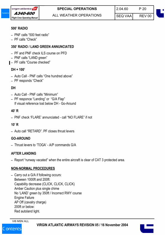
Flight Crew Operating ManualA340-600
500’ RADIO– PNF calls “500 feet radio”– PF calls “Check”
350’ RADIO / LAND GREEN ANNUNCIATED– PF and PNF check ILS course on PFD– PNF calls “LAND green”– PF calls “Course checked”
DH + 100’– Auto Call - PNF calls “One hundred above”– PF responds “Check”
DH– Auto Call - PNF calls “Minimum”– PF responce “Landing” or “G/A Flap”
If visual reference lost below DH - Go-Around
40’ R– PNF check ‘FLARE’ annunciated - call “NO FLARE” if not
10’ R– Auto call “RETARD”. PF closes thrust levers
GO-AROUND– Thrust levers to ‘TOGA’ - A/P commands G/A
AFTER LANDING– Report “runway vacated” when the entire aircraft is clear of CAT 3 protected area.
NON-NORMAL PROCEDURES– Carry out a G/A if following occurs:
Between 1000ft and 200ft:Capability decrease (CLICK, CLICK, CLICK)Amber Caution plus single chimeNo ‘LAND’ green by 350ft / Incorrect RWY courseEngine FailureAP Off (cavalry charge)200ft or below:Red autoland light.
VIRGIN ATLANTIC AIRWAYS REVISION 05 / 16 November 2004
2.04.60 P 21
SEQ VAA REV 00
SPECIAL OPERATIONS
ALL WEATHER OPERATIONS
VI6 MSN ALL
Flight Crew Operating ManualA340-600
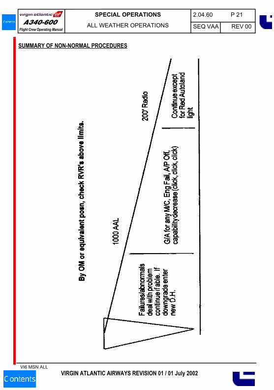
SUMMARY OF NON-NORMAL PROCEDURES
VIRGIN ATLANTIC AIRWAYS REVISION 01 / 01 July 2002
2.04.60 P 22
SEQ VAA REV 00
SPECIAL OPERATIONS
ALL WEATHER OPERATIONS
VI6 MSN ALL
Flight Crew Operating ManualA340-600
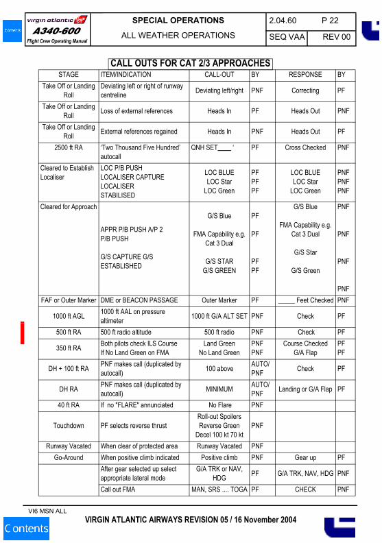
CALL OUTS FOR CAT 2/3 APPROACHESSTAGE ITEM/INDICATION CALL-OUT BY RESPONSE BY
Take Off or Landing Roll
Deviating left or right of runway centreline Deviating left/right PNF Correcting PF
Take Off or Landing Roll Loss of external references Heads In PF Heads Out PNF
Take Off or Landing Roll External references regained Heads In PNF Heads Out PF
2500 ft RA ‘Two Thousand Five Hundred’ autocall
QNH SET____ ‘ PF Cross Checked PNF
Cleared to Establish Localiser
LOC P/B PUSHLOCALISER CAPTURELOCALISERSTABILISED
LOC BLUELOC Star
LOC Green
PFPFPF
LOC BLUELOC Star
LOC Green
PNFPNFPNF
Cleared for Approach
APPR P/B PUSH A/P 2P/B PUSH
G/S CAPTURE G/S ESTABLISHED
G/S Blue
FMA Capability e.g. Cat 3 Dual
G/S STARG/S GREEN
PF
PF
PFPF
G/S Blue
FMA Capability e.g. Cat 3 Dual
G/S Star
G/S Green
PNF
PNF
PNF
PNFFAF or Outer Marker DME or BEACON PASSAGE Outer Marker PF _____ Feet Checked PNF
1000 ft AGL 1000 ft AAL on pressure altimeter 1000 ft G/A ALT SET PNF Check PF
500 ft RA 500 ft radio altitude 500 ft radio PNF Check PF
350 ft RA Both pilots check ILS CourseIf No Land Green on FMA
Land GreenNo Land Green
PNFPNF
Course CheckedG/A Flap
PFPF
DH + 100 ft RA PNF makes call (duplicated by autocall) 100 above AUTO/
PNF Check PF
DH RA PNF makes call (duplicated by autocall) MINIMUM AUTO/
PNF Landing or G/A Flap PF
40 ft RA If no "FLARE" annunciated No Flare PNF
Touchdown PF selects reverse thrustRoll-out Spoilers Reverse Green
Decel 100 kt 70 ktPNF
Runway Vacated When clear of protected area Runway Vacated PNFGo-Around When positive climb indicated Positive climb PNF Gear up PF
After gear selected up select appropriate lateral mode
G/A TRK or NAV, HDG PF G/A TRK, NAV, HDG PNF
Call out FMA MAN, SRS .... TOGA PF CHECK PNF
VIRGIN ATLANTIC AIRWAYS REVISION 05 / 16 November 2004
2.04.60 P 23
SEQ VAA REV 00
SPECIAL OPERATIONS
ALL WEATHER OPERATIONS
VI6 MSN ALL
Flight Crew Operating ManualA340-600
Prior to an LVO approach commanders must check that the required runway has autoland approval forA340 aircraft. This can be done by referring to the Autoland Status List. If approved, runways may beclassified as follows:
STATUS (E) Runway is suitable for Autoland evaluation. Capts are requested to complete theAutoland Report Form about all such autolands.
STATUS (L) Runway is suitable for Autoland. Disengage Autopilot after nosewheel Touch down.During practice or evaluation Autolands, Automatic rollout may be attempted butperformance has not been evaluated.
STATUS (R) Runway is suitable for Autoland with automatic rollout and control.
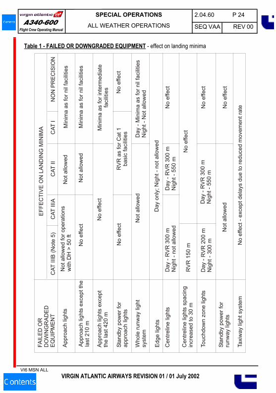
The following table is intended for use both pre-flight and inflight. It is not expected however that thecommander would consult this table after passing the outer marker or equivalent position. If failures ofground aids are announced at such a late stage, the approach could be continued at the commander’sdiscretion. If, however, failures are announced before such a late stage in the approach, their effect onthe approach should be considered as described in the table, and the approach may have to beabandoned to allow this to happen.
AIRFIELDS
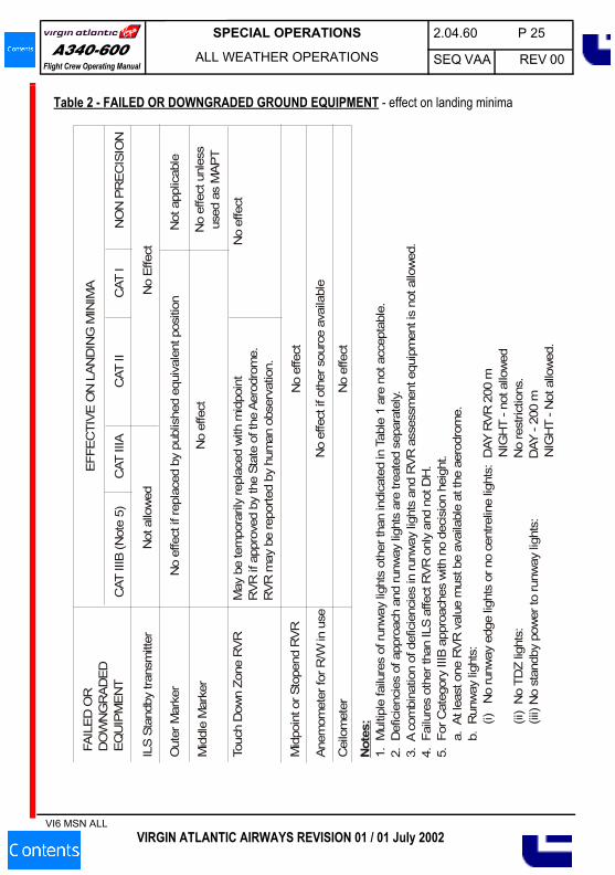
EFFECT ON LANDING MINIMA OF FAILED OR DOWNGRADED GROUND EQUIPMENT
VIRGIN ATLANTIC AIRWAYS REVISION 01 / 01 July 2002
2.04.60 P 24
SEQ VAA REV 00
SPECIAL OPERATIONS
ALL WEATHER OPERATIONS
VI6 MSN ALL
Flight Crew Operating ManualA340-600
Table 1 - FAILED OR DOWNGRADED EQUIPMENT - effect on landing minimaFA
ILE
D O
RD
OW
NG
RA
DE
DE
QU
IPM
ENT
App
roac
h lig
hts
Not
allo
wed
for o
pera
tions
with
DH
> 5
0 ft
App
roac
h lig
hts
exce
pt th
ela
st 2
10 m
App
roac
h lig
hts
exce
ptth
e la
st 4
20 m
Stan
dby
pow
er fo
rap
proa
ch li
ghts
Who
le ru
nway
ligh
tsy
stem
No
effe
ct
No
effe
ct
Not
allo
wed
No
effe
ct
Edg
e lig
hts
Cen
trelin
e lig
hts
Cen
trelin
e lig
hts
spac
ing
incr
ease
d to
30
m
Touc
hdow
n zo
ne li
ghts
Stan
dby
pow
er fo
rru
nway
ligh
ts
Taxi
way
ligh
t sys
tem
EFF
EC
TIV
E O
N L
AN
DIN
G M
INIM
A
Not
allo
wed
Day
onl
y; N
ight
- no
t allo
wed
Min
ima
as fo
r nil
faci
litie
s
Not
allo
wed
Min
ima
as fo
r nil
faci
litie
s
CAT
IIIB
(Not
e 5)
CAT
IIIA
CAT
IIC
AT I
NO
N P
RE
CIS
ION
Day
- R
VR
300
mN
ight
- no
t allo
wed
RV
R 1
50 m
Min
ima
as fo
r int
erm
edia
tefa
cilit
ies
RV
R a
s fo
r Cat
1ba
sic
faci
litie
sN
o ef
fect
Day
- M
inim
a as
for n
il fa
cilit
ies
Nig
ht -
Not
allo
wed
Day
- R
VR
300
mN
ight
- 55
0 m
No
effe
ct
No
effe
ct
Day
- R
VR
200
mN
ight
- 30
0 m
Day
- R
VR
300
mN
ight
- 55
0 m
No
effe
ct
Not
allo
wed
No
effe
ct
No
effe
ct -
exce
pt d
elay
s du
e to
redu
ced
mov
emen
t rat
e
VIRGIN ATLANTIC AIRWAYS REVISION 01 / 01 July 2002
2.04.60 P 25
SEQ VAA REV 00
SPECIAL OPERATIONS
ALL WEATHER OPERATIONS
VI6 MSN ALL
Flight Crew Operating ManualA340-600
Table 2 - FAILED OR DOWNGRADED GROUND EQUIPMENT - effect on landing minimaFA
ILE
D O
RD
OW
NG
RA
DE
DEQ
UIP
ME
NT
ILS
Sta
ndby
tran
smitt
erN
ot a
llow
ed
Out
er M
arke
r
Mid
dle
Mar
ker
Touc
h D
own
Zone
RV
R
Mid
poin
t or S
tope
nd R
VR
No
effe
ct if
repl
aced
by
publ
ishe
d eq
uiva
lent
pos
ition
No
effe
ct
No
effe
ct
May
be
tem
pora
rily
repl
aced
with
mid
poin
tR
VR if
app
rove
d by
the
Stat
e of
the
Aero
drom
e.R
VR m
ay b
e re
porte
d by
hum
an o
bser
vatio
n.
Anem
omet
er fo
r R/W
in u
se
Cei
lom
eter
EFFE
CTI
VE
ON
LAN
DIN
G M
INIM
A No
Effe
ct
No
effe
ct if
oth
er s
ourc
e av
aila
ble
Not
app
licab
le
CAT
IIIB
(Not
e 5)
CAT
IIIA
CAT
IIC
AT I
NO
N P
RE
CIS
ION
No
effe
ct u
nles
sus
ed a
s M
APT
No
effe
ct
No
effe
ct
Not
es:
1. M
ultip
le fa
ilure
s of
runw
ay li
ghts
oth
er th
an in
dica
ted
in T
able
1 a
re n
ot a
ccep
tabl
e.2.
Def
icie
ncie
s of
app
roac
h an
d ru
nway
ligh
ts a
re tr
eate
d se
para
tely.
3. A
com
bina
tion
of d
efic
ienc
ies
in ru
nway
ligh
ts a
nd R
VR
ass
essm
ent e
quip
men
t is
not a
llow
ed.
4. F
ailu
res
othe
r tha
n IL
S af
fect
RV
R o
nly
and
not D
H.
5. F
or C
ateg
ory
IIIB
app
roac
hes
with
no
deci
sion
hei
ght.
a
. A
t lea
st o
ne R
VR
val
ue m
ust b
e av
aila
ble
at th
e ae
rodr
ome.
b
. R
unw
ay li
ghts
:
(i)
No
runw
ay e
dge
light
s or
no
cent
relin
e lig
hts:
DAY
RV
R 2
00 m
NIG
HT
- not
allo
wed
(i
i) N
o TD
Z lig
hts:
N
o re
stric
tions
.
(iii)
No
stan
dby
pow
er to
runw
ay li
ghts
:
DAY
- 20
0 m
NIG
HT
- Not
allo
wed
.
VIRGIN ATLANTIC AIRWAYS REVISION 01 / 01 July 2002
2.04.60 P 26
SEQ VAA REV 00
SPECIAL OPERATIONS
ALL WEATHER OPERATIONS
VI6 MSN ALL
Flight Crew Operating ManualA340-600
USAAPPROVAL
Approved for Cat 2, Cat 3A and Cat 3B approaches.
REQUIRED RVR EQUIPMENTThree transmissometers are normally provided.
TAKE-OFFWhere three RVRs are required, at least two transmissometers must be serviceable reporting RVRvalues at or above the appropriate minima.
CAT 2At least two transmissometers are required when the RVR is less than 1600 ft. The mid point is notrequired but if installed is advisory and may be substituted for the stop end if that is unserviceable. (Notethat midpoint RVR is a company requirement).
CAT 3All three transmissometers are required. The touchdown and mid point are controlling and the mid pointRVR must be reported at or above touchdown RVR.
OPERATING LIMITATIONSTAKE-OFF
For standard take-off minima (defined as ½ statute mile visibility or RVR 2400 ft for airplanes havingmore than two engines), the touchdown RVR report, if available, is controlling.For minima of ¼ statute mile or RVR 1600 ft, adequate visual reference such as runway markings orrunway lighting must be available to allow continuous identification of the take-off surface and somaintain directional control throughout the take-off run. The touchdown zone RVR report is controlling,however the Mid Point RVR may be substituded if the Touchdown RVR report is not available.Note that Pilot assessment of the RVR is not allowed.
APPROACHThe approach ban position is in the Final Approach Fix (FAF).A Cat 2 ILS approach shall not be commenced if the touchdown RVR < 1800ft unless the followingcomponents of the Cat 2 ground system are installed and in normal operation:1. ALSF-1 or ALSF-2 approach lighting system. Sequenced flashing lights are required.2. High intensity runway lights.3. Approved touchdown zone lights and runway centreline lights.4. Maximum crosswind 15 kts.
NATIONAL DIFFERENCES
VIRGIN ATLANTIC AIRWAYS REVISION 05 / 16 November 2004
2.04.60 P 27
SEQ VAA REV 00
SPECIAL OPERATIONS
ALL WEATHER OPERATIONS
VI6 MSN ALL
Flight Crew Operating ManualA340-600
A CAT 3 ILS approach shall not be commenced if the RVR is reported to be less than CAT 2 minimaunless:1. All required elements of the ground system except sequence flashing lights are in normal operation. 2. Maximum crosswind 15 kts.No critical ILS area protection is provided by ATC when the weather is at or above 800 ft and 2 statutemiles visibility.
CHINA
APPROVALApproved for Cat 2 approaches.
REQUIRED RVR EQUIPMENTNo differences.
OPERATING LIMITATIONSRVR increased to 400m if manual control below DH.
JAPAN
APPROVALApproved for Cat 2 and Cat 3A approaches.
REQUIRED RVR EQUIPMENTNo differences.
OPERATING LIMITATIONSNo differences.
SOUTH AFRICA
APPROVALApproved for Cat 2 and Cat 3A approaches.
REQUIRED RVR EQUIPMENTNo differences.
OPERATING LIMITATIONSNo differences.
VIRGIN ATLANTIC AIRWAYS REVISION 05 / 16 November 2004
2.04.60 P 28
SEQ VAA REV 00
SPECIAL OPERATIONS
ALL WEATHER OPERATIONS
VI6 MSN ALL
Flight Crew Operating ManualA340-600
HONG KONG
APPROVALApproved for Cat 2 and Cat 3A approaches.
REQUIRED RVR EQUIPMENTNo differences.
OPERATING LIMITATIONSLanding minima are based on high intensity Approach Lighting System (ALS), Runway centreline (CL),touchdown zone and threshold lighting in use.
INDIA
APPROVALApproved for Cat 2 and Cat 3A approaches.
REQUIRED RVR EQUIPMENTNo differences.
OPERATING LIMITATIONSNo differences.
VIRGIN ATLANTIC AIRWAYS REVISION 05 / 16 November 2004