Embed Size (px)
Citation preview

SCIENTIFIC PROGRAMME


E-BUSINESS IN CE


KEYWORDS
E-business models, business process re-engineering,best practices.
ABSTRACT
The world of business is being revolutionised by theInternet and the World Wide Web. Informationtechnology (IT) opportunities constantly emerge inthis new environment. Despite the financialmeltdown of e-commerce companies, and theiroperational difficulties, companies are stillincreasingly turning to the Internet as commercialgateway. This has given rise to different e-businessformats and platforms, covering a wide range ofbusiness processes, such as sales, procurement,design and manufacturing.
This paper describes a model, which is based on theDavenport functions used in BPR methodology. Itanalyzes the different e-business formats andidentifies which of the Davenport functions theysupport. From this their effectiveness (or lackthereof) is derived.
The model is inspired on the fact that effective e-business portals should be integrated seamlessly intothe business processes of the parent company.Therefore, BPR methodologies could be effective in(re-)designing e-business portals and their functions.The paper illustrates the model with different casestudies.
1. INTRODUCTION
E-Business or e-Commerce includes electronictrading of physical goods and of intangibles such asinformation, between companies and/or privatepersons. E-Commerce has already existed for over20 years, mainly as strictly formatted informationexchange protocols, such as EDI. However, onlyrecently it underwent an explosive developmentbecause of the Internet and the Word Wide Web(WWW).
The key enabling characteristics of the Internet andthe WWW are (Timmers, 2000):
• Availability: 24-hours per day and immediateaccess;
• Ubiquity: global information networks offerworldwide, large-scale and low-cost access to e-commerce everywhere;
• Global: no physical borders for access;• Local: paradoxically, the Internet reinforces
local physical presence and local content;• Digitisation: the real business will increasingly
be happening in information space;• Multimedia: long-awaited combination of
technologies;• Interactivity: appears to overcome the virtuality
of the business relationship, as well as anopportunity for greatly improving traditionalcustomer service and lower price;
• One-to-one: it becomes possible to performindividual customer profiling;
• Network effects and network externalities: lowcost and fast growth in the number ofrelationships and;
• Integration: add value-combining informationacross steps of the value chain.
E-Business uses connected marketplaces, theInternet and IT opportunities. It has changed therules of the market and the role of information --technology to create value for customers and for thefirm.
2. IT OPPORTUNITIES
If one cuts through the hype and technologicaljargon of many e-business platforms, what remainsis a new “toolbox” of communication andinformation processing techniques. Just as any otherbusiness support technology, such as ERP,successful use will depend heavily on the extent towhich companies can introduce these technologiesseamlessly into their business processes (VanLandeghem et al, 1999). It is therefore useful toanalyze e-business technology as another ICT tool,with respect to the opportunities it could provide. Agood analytical framework of the ICT impact onbusiness processes has been described by Davenport
A BUSINESS PROCESS REENGINEERING FRAMEWORKFOR ANALYZING E-COMMERCE EFFECTIVENESS
Hendrik VAN LANDEGHEM*, Emma BERGARECHE CAÑABATE**
*Department of Industrial Management, **Escola Tècnica Superior d’Enginyeria Ghent University Industrial de Barcelona, UPC 9052 GENT, BELGIUM Barcelona, Spain
Email: [email protected]

(1993). In Table I we list the 9 basic impact formatsof ICT, and we provide for each format examples ofcompanies, whose WWW platform is particularlydesigned for the specific function. These examples
have been described at length in (Bergareche, 2002).Due to space limitations, we include only excerpts inthis paper.
IMPACT EXPLANATION EXAMPLES
(Bergareche, 2002), (Timmer, 2000)
Automational Eliminating human labor from a process Caesma S.L., Amazon, Virgin
Informational Capturing process information forpurposes of understanding
eBay, Cydesa, Frape Behr
Sequential Changing process sequence, or enablingparallelism
Team Center, Kodak, Phoenix MutualLife
Tracking Closely monitoring process status andobjects
MRW, Johnson&Johnson, DHL
Analytical Improving analysis of information fordecision making
Storm (Linear Systems), Amazon,Progressive insurance of Cleveland,American Express
Geographical Coordinating processes across distancesHewlett Packard, Frape Behr, Ford,General Motors, United Parcel Service
Integrative Coordination between tasks and processesCentre CIM, Hospitals,ComercialLoans, Insurances
Intellectual Capturing and distributing intellectualassets
Ford, American Airlines, The Big Sixand other accounting firms
Disintermediating Eliminating intermediaries from a process Pefa, Virgin Express
Table I. Davenport functions of ICT, with examples from WWW platforms
3. E-BUSINESS MODELS
An e-business model is defined as the organisationof product, service and information flows, withspecific sources of revenues and benefits forsuppliers and customers. Suppliers and customersinteract, sometimes throughout intermediaries,using technology to attain better communicationsand lower transaction costs.
Information and communication technology enablea wide range of business models. Timmer (2000)has written a landmark book describing different e-business models, with some examples. In table IIwe provide an overview of these models, which wesubsequently will match with the Davenportfunctions of Table I.
4. RELATIONSHIPS BETWEEN ITOPPORTUNITIES AND E-BUSINESSMODELS
Referring to Table II, E-Shops open a new channelof advertisement, promotion, and more and morethe possibility of purchasing with low transactioncosts. Cost does not increase because human labour
is not needed to offer a 24-hour service throughoutthe Web. Land’s End, an online clothing shop, usesthis opportunity, “automational”, although the firmis also still sending letters by traditional mail.
In some cases we can also see the impact of theinformational opportunity. For example, Land’sEnd captures customers’ behaviour to improve itsservices. This online store offers the opportunity totheir customers to have access to their order status,which implies the use of the tracking opportunity.When e-shops allow ordering and paying online,co-ordination across distances is needed to assurecustomers satisfaction. For instance, Fleurop, whichsells and distributes flowers, co-ordinates sales andlogistic processes across several places. Land’s Enduses the integrative and the sequential functionalityin a basic way. They co-ordinate tasks with UPS.However, the firm should improve the use of thegeographical impact because nowadays orders fromoutside of the U.S cannot take advantage of all theWeb offerings.
An e-mall is a group of e-shops, therefore, like inthe e-shop model, human labour is reduced, andeven more than in the e-shop model, the

geographical opportunity is exploited. A lot ofshops work from different locations sharing somefeatures. However, in most cases co-ordinationbetween the e-shops has to be improved. An e-mallhas to work in an environment of security. Quality
and delivery reliability has to be guaranteed, oftenby third parties, if we want to gather the bestsuppliers. In this regard, the e-mall concept addsvalue to the e-shops by providing a brand-likequality guarantee to its customers.
E-BUSINESSMODELS EXPLANATION EXAMPLES
E-Shop Electronic form of a traditional shop. Basic Webpresence, sometimes with possibilities to order.
Lands’ End, Fleurop,Travelocity, Merck-ltd.
E-Mall Collection of e-shops, usually enhanced by acommon feature or theme.
Industry Net, Abalone Web,EMall, Browser Mall.
Third PartyMarketplace
Portal function to create a marketplace withmultiple buyers and sellers, often within aspecific industry sector.
Tradezone, Amazon AssociatesProgramme, Citius.
E-ProcurementElectronic tendering and procurement of goodsand services. A purchasing portal widens thesupplier base and reduces transaction costs.
Autochain, Japan Airlines,Epylon.
E-AuctionOffers an electronic implementation of biddingmechanisms also known from traditionalauctions.
eBay, Fast Parts, Pefa, EauctionRoom.
InformationBrokerage, Trustand Other services
Information services are emerging to add valueto the huge amounts of data available on theopen networks. Trust services provide basicsecurity technology to Net parties.
Google, Verisign, Belsign, TiaaCref, Fulton Financial Advisors.
Value-ChainService Provider
Specialised in a specific function for the valuechain.
CheckFree, FedEx.
Virtual CommunityGathering different parties with the sameinterests to add value sharing these commoninterests.
Amazon, Indconnect, Apparelex,Yahoo.
CollaborationPlatform
Provides a set of tools and an informationenvironment for collaboration between andwithin enterprises for trade, design ormanufacturing purposes.
Vastera’s CollaborativePlatform, Commerce OneCollaborative Platform, VALinux, Colaboris.
Value-ChainIntegrator
Integrates multiple steps of the value chain, withpotential to exploit the information flowbetween those steps as further added value.
Marshall, Commerce Questformerly known as AdvancedNetwork Solutions,TRANS2000, UPS.
Table II. e-Business Models, as defined by Timmer (2000)
Third Party Marketplaces gather a wide range ofsuppliers and customers, assuring security oftenapplying sophisticated algorithms. Processes shouldbe co-ordinated across distances. Interactionbetween participants has to be co-ordinated too. InTradezone, for instance, the key issue is to achievethe co-ordination between multiple catalogues toassure satisfaction of both suppliers and buyers. Insome cases we can distinguish the informationaland analytical impact. For example, AmazonAssociates captures consumers’ behaviour, buyingpatterns and suggests substitute products.Furthermore, customers can access their orderstatus. Third Party Marketplaces offer a wide range
of services almost without human labour;Tradezone offers complete processes online,enabling processes parallelism. The firm shouldimprove the use of the disintermediatingopportunity bypassing some middlemen by addingonline information, but this will only be possible iftrust in e-business increases.
An important feature of e-procurement is the widechoice of suppliers. Customers can purchase onlinecustomised items from the selected suppliers. Toachieve a time reduction it is necessary to automaterequests and bids. As in Epylon, the quality ofservice is enhanced allowing control of the process

status with the tracking opportunity. If a companywants to develop this model correctly it has to usethe sequential functionality. Workflow has to beallowed between customer and supplier and alsobetween different departments of a firm.Parallelism between processes has to be enabled.For example, in Epylon customers ask forquotations from different suppliers at the same timeand then they can compare responses on a singlescreen.
E-auction enables a true disintermediation, forinstance with PEFA (an online fish auction)fishermen can sell their catch directly to the finalretail consumer. However, not all of theintermediaries are bypassed in this model. Somepeople are needed to assure the quality becauseconsumers cannot see what they are going topurchase. To achieve profit applying this model,co-ordination between all the participants, and theirroles in their different locations, has to be assured.In the eBay example we can see the impact of theinformational opportunity. eBay is an onlineconsumer-to-consumer auction that collectscustomers’ behaviours, information about theduration of each auction, etc. to improve its service.E-auctions often allows consumers to monitorprocess status and even to have them alerted(through paging or email) when the price onselected items reaches a certainthreshold.
Information Brokerage, Trust Services,and Consultancy add value to theavailable data. They aim to helpconsumers, firms or people, to achievebetter financial results, services,information, etc. These firms shouldcapture customers’ behaviour. Tooptimise the obtained results one shoulduse complicated algorithms anddistribute them to all the interestedparties, as for instance, Fulton FinancialAdvisors does. Offering universalservices increases the company’sbenefits and the customer’s trust. Forexample, we have studied the case ofVerisign that offers security servicesaround the world endorsed with itsworldwide brand. The automationalopportunity can reduce errors.
The Value-Chain Service Providermodel has to enable the co-ordination
between several tasks. We have seen that FedEx co-ordinates shipment requests and carriers. To offer acomplete service firms should offer an easy accessto the transport status around the world. It could beuseful to apply computer programmes to optimiseservices. FedEx is also applying a sophisticatedprogramme to select the most suitable routes todeliver an item. Sometimes Value-chain Providerscapture and distribute intellectual assets. Forinstance, FedEx provides training about logistics.
Virtual Communities gather different parties aroundthe world that share knowledge and interests. Thesecompanies can increase the quality of their servicesoffering the possibility of monitoring processstatus. Participants can review their last operations.In this model processes can be donesimultaneously. The order of traditional business’processes often changes. Virtual Communities offera complete service where different process must beco-ordinated. Furthermore, we have seen theanalytical impact in Amazon where the firmcollects information about its customers and then isable to offer customised products.
Collaborative Platforms link applications co-ordinating tasks and processes across distances. Forinstance, the design of different parts of a car canbe done in different departments or even indifferent countries that work co-ordinated. Some
NECESSARY/CRUCIAL
RECOMMENDED/USEFUL
AU
TO
MA
TIO
NA
L
INF
OR
MA
TIO
NA
L
SE
QU
EN
TIA
L
TR
AC
KIN
G
AN
AL
YT
ICA
L
GE
OG
RA
PH
ICA
L
INT
EG
RA
TIV
E
INT
EL
LE
CT
UA
L
DIS
INT
ER
ME
DIA
TIN
G
E-SHOP
E-MALL
THIRD PARTY
MARKETPLACE
E-PROCUREMENT
E-AUCTION
INFORMATION
BROKERAGE
VALUE CHAIN
SERVICE
PROVIDER
VIRTUAL
COMMUNITY
COLLABORATION
PLATFORM
VALUE CHAIN
INTEGRATION
Figure 1. Ideal Davenport functions for each e-Business Model.
Legend of figure 1:

processes that usually were sequentially developedcan be done in parallel. We recommend the use ofthe tracking opportunity in collaborative platforms;it can make the work easy. Intellectual assets haveto be captured and distributed between participantsto enhance the efficiency. We have identified, forexample in the case of VA Linux, that engineersshare information during product and processdevelopment. Engineers can capture processinformation. Knowledge is distributed throughoutthe firm.
Finally, Value-Chain Integrator co-ordinatesmultiples steps of the value-chain capturinginformation. Application systems among tradingpartners and customers are integrated. Parallelismbetween tasks, processes and files broadcast isenabled. Workflow is secure and reliable. Thedistribution of intellectual assets is possible. Forexample, we have studied the case of AdvancedNetwork Solutions. They offer training tocustomers and share knowledge and experiencewith them. The model has to co-ordinate a completeservice, along the different steps of the value-chain,across distances.
We have combined the results of the above analysisin two figures. Figure 1 shows, for each e-businessmodel, the “ideal” set of Davenport functions thatare necessary and useful. Figure 2 shows for aselected set of examples, which opportunities theyhave left open.
5. CONCLUSIONS
From inspection of figures 1 and 2, while payingattention to the relationship –found between e-business models and the opportunities offered bythe information ----technology, -we conclude that:• The automational and the geographical
opportunities are the most used -in current e-business models. But alone, they cannotachieve competitive leadership of -e-businessin the world.
• The use of the informational, the intellectualand the analytical functions has to beimproved, nowadays they are the least applied.The use of information has to increase. Sharinginformation should add value to achieve trueimprovements, customer satisfaction andbenefits.
By incorporating the proposed frameworkin the design of new e-business platforms,one should be able to achieve moreeffectiveness and enhanced customer value.
References
Bergareche Cañabate, 2002. Analysis of e-business Best Practices, Master’s ThesisGhent University, Promotor: H. VanLandeghem, 186 pp.
Davenport T.H., 1993. Reengineering.Work through Information technology,Harvard Business School Press, U.S.A..
Timmers, P., 2000. Electronic commerce:strategic and models for business-to-business trading, John Wiley & Sons Ltd.
Van Landeghem H., Reeve R. , ReterinkH., 1999. Benefits from ERP (in Dutch),Berenschot, 72 pp
They are doing it.
They should do it.
AU
TO
MA
TIO
NA
L
INF
OR
MA
TIO
NA
L
SE
QU
EN
TIA
L
TR
AC
KIN
G
AN
AL
YT
ICA
L
GE
OG
RA
PH
ICA
L
INT
EG
RA
TIV
E
INT
EL
LE
CT
UA
L
DIS
INT
ER
ME
DIA
TIN
G
LANS’ END
BROWSER MALL
TRADEZONE
EPYLON
eBay
PEFA
VERISIGN
FULTON FINANCIAL ADVISORS
CHECK FREE
AMAZON
VA LINUX
MARSHALL
Figure 2. ICT Opportunities for selected e-business examples

© SCS
New businesses on The Net: the digital object handling services
Sebastiano Sighinolfi, Matteo Mattioli, Mario SalmonDemocenter, viale Virgilio 55, 41100 Modena, Italy
Tel +39 059 899611 Fax +39 059 848630Email: [email protected], [email protected]
KEYWORDSE-enginering, digital object handling, e-engineering, e-marketplace, virtual incubator of enterprises.
ABSTRACTThis paper presents the results achieved in the scope of theIPS029077PR-TEMA project “TElematic MArket ofservices related to Digital Objects”, co-funded by theEuropean Commission in the framework of the “Innovation& SMEs” programme. Two aspects have been deeplystudied in this project: the first is the growing profitabilityof online computational services that grouped in an Internetportal can build a real market of digital object handlingservices. Digital object handling in the scope of themanufacturing has the meaning of engineering activitiesbased on digital models of parts and assemblies. The natureof the cited activities makes Internet the ideal channel torun the business, nevertheless the new online marketplaceneeds to reach a critical mass in order to be trusted andbecome a successful business.
For this reason, the second aspect faced by the TEMAproject concerned the support to the creation of newcompanies capable to join the e-marketplace and contributeto the creation of a virtual community, reaching therequired critical mass for the marketplace. TEMAdeveloped a methodology for strengthening the businessidea of applicant entrepreneurs wishing to operate in thedigital object handling market, also making them availablesome web-based tools useful in analysing their idea ofdigital object handling service.
By the project end, TEMA is achieving two results: anInternet portal representing the first prototype of e-engineering marketplace, used for testing someexperimental services of Digital Object Handling. Thesecond result is the TEMA Virtual Incubator of e-services,a web-site publishing the TEMA methodology and a bundleof services for the market analysis and the financialplanning of any new business idea that could launch a newdigital object handling service.
INTRODUCTION
The term “digital object handling” can be used to embrace awide range of activities related to the computation,exchange and management of digital information, namelydigital objects. The Engineering-oriented companies are theprincipal users of computer-based technologies supporting
the best in class treatment of their product data. Plenty ofcomputations are the core of software tools useful toimprove the quality of the product life-cycle, in particularduring the design phase. There are different kinds ofsimulations, modelling, translations and analysis, reducingthe time to market of the new products, the costs of thedevelopment, the quality and the accuracy of the resultsnecessary to move from the idea to the target good.
All the digital object handling techniques contributing tothe development, validation and test of digital models havea potential market in the development of Internet servicesaddressing the satisfaction of the demand of manufacturingcompanies, despite of their location. Since digital objecthandling services are just requiring digital data to producetheir results, they find in the Internet based technology aunique business chance for the marketing and the servicedelivering to customers all over the world, actuallyoperating in the global marketplace. From the other hand,any company wishing to take advantage of latestcomputational technology for the development of theirproducts, even lacking competencies for that, can outsourcethe desired computation by purchasing the proper onlineservice.
Actually a virtual market of digital object handling servicesis not yet operating, but new providers appear on themarket, while connectivity problems and bottlenecks inInternet are falling. In other worlds, it can be perceived thepotential of the e-engineering market while the technologyis more and more mature for supporting it. Apart from thebenefit of a virtual market collecting the different offers ofservices, a problem exists in the approach of the smallenterprises. Potential customers of the digital objecthandling services should not be large companies, whichshould have internal resources and departments in charge ofthe required digital object handling. Potential customers canbe likely identified in middle and small companiesdeveloping their own products and capable to perceive theimportance of the computational services related to theproducts design and engineering, but hindered in their use.
As a matter of fact, small and very small companies are notused to get advantage of digital object handling services,they face difficulties in approaching such technologies andthey can not devote resources to purchase them or to trainemployees to use them properly. Also, most of them are notused to search and buy services and goods in Internet.
It is feasible to depict a scenario where the InformationSociety is ready to satisfy the demand of the companies, but

© SCS
many target users, in particular very small SME, aredistrustful. Partially this situation is due to the difficultiesof the so called new economy, that demonstrated theweakness of an economic system where investments,speculations, profits and bankruptcies have been reiteratedat a ceaseless rate. Even so, the new economy is just thepresent economy and companies started to perceive thepotentiality and the benefits of the Internet-based economy.No businesses can neglect the expectancies of customersmore and more attracted by the Internet world, as aconsequence no companies can just wait for the nextevents.
Internet is strongly committed to become the moreconvenient and effective media providing information tothe widest and heterogeneous public. Yesterday Internetwas a competitive advantage for the pioneers of the neweconomy who survived, today and in the future it representsa competitive requirement for any company that will makea proper use of The Net.
Digital Object Handling services (DOH)
In the world of small and very small companies, where it isnot easy to introduce ICT support systems, theentrepreneurial associations play the major role ofstimulating the entry of the Information Society. Theseassociations are starting to provide online services to theirassociated, for example systems to automate payrolls andinvoicing.Managers in any company are conscious about theimportance of being in time for the meeting with theInformation Society and get advantage of the numerousopportunities for the best run of their core activities.Missing the appointment should be harmful, in particular inthe coming years, since acting in the global marketplacenecessarily imposes the companies to be dynamic andhighly competitive. In this days it is already clear thatinformation is even more precious than physical assets, inparticular for networked organisations that are foundedupon collaborative activities co-ordinated thanks virtualvalue networks of information. The opportunity of the e-engineering is enhancing the perception of the higherinformation value, thanks to the chance that every companyhas for improving its overall business.
In this panorama the digital object handling is promisingfunctional and qualitative improvements to products andprocesses of the customers, namely a competitiveadvantage previously almost exclusively owned by leadercompanies of given markets. Industries should pay attentionto the digital object handling services delivered online andthe benefits they offer. There are many reasons justifyingthis:
Ø Internet is the most suitable media to sell and get theresults of the digital object handling computations.Why renouncing the best ones if they are just one clickfar and they allow to recover or reduce the delay withrespect to market leaders?
Ø Even if the digital objects contain company know-how,they can travel on the Net in a secure and easy way,
being protected from hacker attacks. Latest securitytechnologies allow companies to trust the e-business.
Ø Any company can take advantage of the DOH formaintaining or improving the desired level ofcompetitiveness, establishing partnerships withcompanies that are specialised in the required DOHservices. The market would create competition amongservice providers, making more profitable the use ofthe services.
Ø Customer companies get the possibility of outsourcingthe required DOH processes to service providers,neglecting their location in the world.
Ø Finally, Internet allows any enterprise to gain access tocompetencies and technologies of specialised experts,with the lowest costs.
This opportunity can be collected not only by companiesalready used to exploit DOH processes, but also bycompanies not used to do so. In particular it is anopportunity for many SME used to work just assubcontractors of larger firms. They can acquire a majorcontrol of their processes, improve and differentiate them,increasing their competitiveness and their offer, alsosupporting their entrance in new markets.
THE TEMA PROJECT
The TEMA project aims at proving applicant entrepreneurswith support tools for the start-up of their innovative firms,in particular companies delivering online DOH services,besides stimulating the creation of a virtual marketplacehosting the new created services. The objective of the e-marketplace is to make easier for customer to identify thedesired services, besides guaranteeing the quality and theearnestness of the hosted DOH providers.
As a matter of fact, virtual communities are the premiersites where building and fostering the necessary businesstrust. The birth of an actual virtual market of digital objecthandling services is more hindered by the culture of peoplethan by the technology. This is particularly true for SMEs,where entrepreneurs dislike changes, in particularconcerning the introduction of new ICT tools in theircompany. The biggest potential of the DOH services isactually here. Companies can verify and test or make anextensive use of the desired services, without side-effectson their core business. In other words, they can get themaximum benefits, the best technologies and competenciesjust paying for the lower costs.
The TEMA project started in September 2000 and itfinishes in April 2002. Major result of the project is madeof two guidebooks for DOH companies start-up. Theseguidelines are available on the project website, togetherinteractive tools for business planning and market research.Both guidelines and tools are available for registered usersand registration is free of charge.
The guidelines

© SCS
The guidelines are aimed at strengthening theentrepreneurial spirit and the business idea of people, beingthe objective of TEMA to stimulate and support thecreation of new DOH services. The themes discussed in theguidelines belong to two main fields: (i) the DOH companystart-up path discussed step by step; (ii) the creation of themarket interface, that is the Internet portal supporting theDOH business run.
Selling services online is typically a business-to-businessactivity, even if differentiation in the applied businessmodels could be revealed for services focused on differentareas. To start up a digital object handling business meansto launch new services that are very innovative in the actualmarket. For this reason, even if the DOH companyperforms an online business that is a particularly riskyactivity, such a company should also have a big advantage:it offers a range of services whose importance is wellknown by the target customers, namely a market made ofcompanies that can not be unsteady and seasonal. Theservices are not accessory, they can support the corebusiness of the customers for the benefits of theircompetitiveness.
In order to ensure expressiveness to the guidelines and theirmost effective and widest use, they are published in theTEMA Virtual Incubator website in hyper textual format,besides being integrated with interactive tools allowing theuser to easily apply the guidelines to his business case. Theinteractive tools support the market analysis and a financialplanning for any DOH business. The TEMA VirtualIncubator is now published at the address
http://www.tema.democenter.it.
The TEMA guidelines presents the start-up path of a DOHservice by taking into account its peculiarities, discussingspecific arguments like the technological requirements ofthe market interface, the European directives regulating theonline business, the business process and many othertopics. The start-up path is subdivided in the followingmain steps (see also Figure 1 and Figure 2):
• Market analysis: the debate concerning the opportunityof performing a market investigation before enteringthe market with a new product or service is far to beconcluded. Market researches are expensive, they taketime, also sometimes a market research has been wrongaffecting the good results of a business, in particularwhen new technologies were involved. TEMA wishesto help people in identifying their potential market andit suggests a methodology to evaluate the market nicheof a given DOH service, using data aggregated at theEuropean level.
• Planning: the creation and management of a newbusiness must be carefully evaluated from the financialpoint of view. Not all people having a business ideacan study by himself the financial implications of hisidea, that’s why TEMA provides two differentapproaches: a budgetary analysis that can be used alsoby people not used to deal with financial planning, anda second level of analysis providing more detailed
results but requiring more effort and experience fromthe user.
D.O.H. start up
MARKET PREREQUISITES PLANNING
BUSINESS PROCESS
ORGANIZATION FUNDING
HW & SW ACQUISITION
INCORPORATION
MARKET INTERFACE
TECHNOLOGY SUPPORT
MARKETING PLAN
SKILLS & TEAM
DEFINITION
MARKET RESEARCH
MARKET SELECTION
Figure 1 – Breakdown structure for DOH start-up
Figure 2 - Pert diagram of the DOH start up
• Skills and team definition: any DOH service is abusiness requiring a range of capacities and skills inmany different fields. Even if a small team can carryout the business, its members must sum up the fullrange of roles required to ensure the propermanagement, quality and performance of the DOHservice.
• Business process: providing online a DOH servicerequires to follow a proper business process, alsotaking into account a set of rules coming from theregulation of the e-businesses.
• Incorporation: there are different opportunities forcreating a new company. Different models exists in anyEuropean member state, having different requirementsand providing different opportunities. According tothese, entrepreneurs can reason about the incorporationmodel that is better fitting its requirements andpossibilities.
• Marketing plan: even before starting to operate on themarket, a DOH company must set up its marketingplan. In this era Internet is providing big chances to thebusinesses and is completing a marketing mix thatmust still take advantage of traditional media, in orderto provide the proper company image and servicemarketing to different categories of audience.
• Hardware and software acquisition: a DOH business isbased on the ICT technologies, both for providing anddelivering the DOH services. It is necessary to evaluateand select the proper communication platform,implement all the functional services necessary toguarantee the performances required by the customers,besides to procure the application-specific platform tocarry out the process of digital object handling.

© SCS
Relevance has been given to the Market Interface analysis,as it is fundamental for the effectiveness of the onlinebusiness wishing to sell in Internet the services. ActuallyInternet is the unique channel to reach the customers andthe setting up of the market interface must take care ofmany elements to fit the requirements of an e-business.
The matrices complex
In order to help users in applying the methodologydeveloped in the guidelines, the Virtual Incubator has beenenriched with two active applications. One of this is thematrices complex. By means of this tool, the user isguided through a Market analysis, helping him to findinteresting market data, about the particular kinds ofmanipulation he is interested in and about the differentindustrial sectors which use them. This analysis is donethrough the combined reading of given matrices: Relevancematrix; Present use matrix; DOH matrix; Segmentationmatrix; Prospect niche matrix. Scope of the tool is not justto provide data for a sample of DOH services, it is alsopromoting a research methodology that allows the users tolearn the principles of the investigation.
The business plan builder
This application aims to assist the future entrepreneur alongthe path from the conception of his business idea to theconscious definition of his future business activity. Theresult of the interaction between the customer and theapplication consists of a preliminary Business Plan and auser exercise in understanding the requirements of hisbusiness.
The importance of writing a good Business Plan isuniversally recognized and almost all the traditionalincubators supply documents recommending contents,document structure and style of this milestone of thebusiness creation. The business plan builder empowers theapplicant entrepreneurs combining the editing functions fortheir own business plan with the evaluation of the achievedresults, providing benchmarking parameters, visualindicators and aids to understand results of their financialdrafting.
As such a document laying out economic and financialprogramming can be very complex and it is a vital elementfor the profitable start-up of a firm, the document resultingfrom the use of the application can not be considered a finalplan. The virtual incubator will allow the users to buildtheir own preliminary business plan. Such a document willbe a reliable base from which to start writing the final BP,maybe with a professional adviser. The preliminaryBusiness Plan is composed of several main sections, suchas:
1. Entrepreneur presentation and business introduction.2. Strategic planning and Market analysis.3. Operative planning, Cost analysis and Financial
considerations.4. Projection of the estimated economic results.
The third Section “Operative planning, Cost analysis andFinancial considerations” allows the preparation of severalsectional budgets: Sales budget; Direct Costs budget;Employees budget; Capital budget; Amortizations budget;General Costs budget; Financial budget.
This set of budgets is easy to draw up and to understand byany user of the virtual incubator, but the counterpart of thiseasiness of use is a financial analysis not very deepened.Stopping to this level, a prospective entrepreneur missesdetailed information that would be relevant in thefollowing, when facing the final business plan.Nevertheless, the user has available schemes to getprojections of the cash flow and analysis of financial indexvariations. The tools made available by TEMA are:
• Variations Analysis: an instrument that enables theuser to do a rapid and direct comparison among theeconomic results obtained with the data put in thesectional budgets, and the ones derived by somespecified percentage variations on the different items.
• Cash Flow Analysis: a facility with the aim ofdisplaying to the user possible Cash Flow series forthe first twelve months of operation of his company,in order to discover lacks of money.
For users being already used to deal with financialplanning, TEMA proposes also the forth Section“Projection of the estimated economic results” (in depthanalysis). In this section a user will get available a moreexhaustive and detailed tool to perform the financialanalysis. The deeper level of financial investigation forcesthe user to do a hard work for the financial parsing and thetracing of the proper data. As obvious, this hard work leadthe user to more detailed data and indicators.
The showcase
The last phase of the project has been dedicated to thepreparation and execution of a showcase aimed atsimulating a marketplace of digital object handlingservices. The experimentation concerned four serviceswhere the handling of digital objects plays a fundamentalrole in the achievement of the final result: reverseengineering; simulation of plastic injection, CAD formattranslation and rapid prototyping. The prototype of themarket portal is published at the address
http://tema.tekniker.es/temas.php
Thanks to the experiment it has been feasible to verify eachfunction of the marketplace devoted to the business run,besides testing the market interface of each service and therelated management functionality.
The experiments concerned two real industrial casesinvolving a sequence of DOH services for reaching thedesired goal. A first trial concerned the reshaping andrestyling of a perfume bottle, a second case lead to the

© SCS
production of a prototype of plastic gear. For the first trialthe sequence of required services has been reverseengineering, CAD translation, rapid prototyping. During thesecond trial the service involved were CAD translation,plastic injection simulation, rapid prototyping. For eachservice the proper market interface has been used to agreethe terms of the business, collect the problem requirementsand perform the service. By the end of the experimentphase it has been possible to collect all the strength andweakness point of the market portal, with the aim ofreducing the time to market of a real Internet marketplaceof e-services.
CONCLUSION
The TEMA project has investigated a very promisingmarket, that is the market of engineering-related services.Such services find their natural business channel in Internet,but despite of the effort spent for the transaction from theold economy to the new economy, a number of cultural andtrust-related problems hindered so far the online businesssoar, compromising the survival of many dot-comcompanies. This can be the main reason why only fewproviders are delivering DOH services online. Neverthelessthere is a strong commitment of governments and agrowing desire of companies and citizens to improve andconsolidate their relation with the Information Society.Technology is mature to support the widest implementationof the new online business, with continuous effort to ensurethe desired level of security and the reduction ofbottlenecks in connectivity.
It is according to this perception and to the impossibility ofrenouncing to the technical and cultural progress gained sofar that TEMA acts for stimulating the creation of a InternetDOH marketplace. The digital object handling has theopportunity to become a profitable online business, both forskilled providers and customer companies outsourcingspecialised computational services. TEMA verified thefeasibility of the online DOH business and implemented ameasure for supporting the development of new services.
The use of the achieved results and the lesson learnt fromthe trial will be addressed toward the integration withcomplementary competencies and tools, so that to succeedin fostering the DOH marketplace. First of all the virtualincubator would be integrated with traditional businessdevelopment measures, building a support frameworkcapable to act from the business idea development to thecompany start-up. Second, partners of the TEMAconsortium are capable to initiate a marketplace by meansof their own services, giving reason to the first run of themarket. Finally, such a marketplace would represent theentry market for any new DOH provider companydeveloped through the TEMA guidelines and supported inits development.
REFERENCES
“Business models for electronic markets”, P. Timmers, EC,Directorate-General III, April 1998
Directive 97/7/EC of the European Parliament and of the Councilof 20 May 1997 on the protection of consumers in respect ofdistance contracts. Official Journal L 144 , 04/06/1997 p. 0019 –0027
“Legal Issues of Electronic Commerce – A practical guide forSMEs”, ECLIP ESPRIT project 27028
“D04.1 - Start up guidebook”, TEMA project IPS029077PR, 2001
“D04.2 - Market interface guidebook”, TEMA projectIPS029077PR, 2001
“D06 - Market trial”, TEMA project IPS029077PR, 2002
“D08.1 – Exploitation plan”, TEMA project IPS029077PR, 2002
AUTHOR BIOGRAPHY
SEBASTIANO SIGHINOLFI is a researcher of theInnovation department of DemoCenter. He graduated incomputer science at the University of Modena with highestgrade in 1997. Since 1998 he is involved in national andEU funded projects, being in charge of projectmanagement, software analysis and development. Otherpublications:"An SME-targeted Process Model for Non-conventionalProcesses", Prof. F. Bonfatti, Dott. P.D. Monari (Universityof Modena), S.Sighinolfi (Democenter), QMS ISBN 1901782 03 4“A process model harmonising manufacturing and atypicalactivities” Prof. F. Bonfatti, Dott. P.D. Monari(Dipartimento Scienze dell'Ingegneria, università diModena), S.Sighinolfi (Democenter), B.I.T.newsletter1999, SITECH.“RDSS: a Recycling Decision Support System to pursuegreen manufacturing” Prof. F. Bonfatti, Dott. P.D. Monari(Dipartimento Scienze dell'Ingegneria, università diModena), S.Sighinolfi (Democenter), "PDT Europe 2000",May 2000, Noordwijk, The Netherlands“A computer-supported process model for lean and greenmanufacturing” Prof. F. Bonfatti, Dott. P.D. Monari(Dipartimento Scienze dell'Ingegneria, università diModena), S.Sighinolfi (Democenter), 2000 InternationalCIRP Design Seminar, 16-18 maggio 2000, Haifa, Israel“Enhanced modelling and DSS tools to support greenmanufacturing” Prof. F. Bonfatti, Dott. P.D. Monari(Dipartimento Scienze dell'Ingegneria, università diModena), S.Sighinolfi (Democenter), "MIM 2000", 12-14Luglio 2000, Patrasso, Greece"Dal technigrafo alla rete: la e-progettazione",S.Sighinolfi, M.Salmon, "Componenti industriali",December 2001

Practical Experiences with B2B Applications Karl Strecker, Matthias Stroezel
SSC Services GmbH Gewerbestraße 42
D-70565 Stuttgart
Email: [email protected]
INTRODUCTION
For the requirement of shorter development times it becomes more and more important for the automo-tive industry to offer simple possibilities of direct EDM access on bill on materials, iCAD geometries, assemblies, standards and specifications. As the variety of different information systems is enor-mous (in many cases historically grown), this be-comes one the of most important tasks which auto-motive enterprises have to deal with in order to remain competitive and innovative.
This abstract explains the process to offer all in-formation necessary for the development and pro-duction of a vehicle in a simple WebBrowser GUI using the example “Integration of Product and Process Description” of the Mercedes-Benz devel-opment process at DaimlerChrysler. Through this, benefits such as increased process reliability, early data provision and reduction of costs will result.
PROJECT DESCRIPTION
Currently, the design of body in white parts with the CAD system CATIA in the Mercedes-Benz development process at DaimlerChrysler is com-pletely digital. This means, that single parts and assemblies are designed three-dimensional on the computer and not, as in former times, exclusively on the drawing board as a 2-D drawing. Up until now, technical drawings which had been derived from the 3-D data files, were required as obligatory documents for the documentation and release of components and thus also for those of the design of further organisational ranges, such as prototypes, production planning and plants. In many areas today, such as by the generation of operation equip-ment/facilities and test specifications of free form surfaces in raw parts, for example, 3-D data files are more frequently used directly. However, the 3-D data file does not contain all the process-relevant information. Only the drawing contains all neces-sary information.
The project “Integration of Product and Process Description” has the goal that all information nec-essary for the development and production of a vehicle is contained in the 3-D data file. All partici-pants in the process will have access to this data, whereby the technical drawing can then be omitted.
For the development/design and documentation without drawings, it will be ensured that all geo-metrical, process-relevant and organisational in-formation of the components will be filed structur-ally in the 3-D data file. The implementation of the “drawingless” procedure in the following ranges, such as prototype construction, production planning and plants, makes new demands on the working processes. With the omission of drawings, the in-formation for the design of operating equip-ment/facilities and workshops, for example, will be derived from the 3-D data files. A web-based eEn-gineering portal with integrated visualisation tools which are harmonised with the working processes must be employed. In order to ensure a reliable implementation, the requirements on the use of 3-D data files will be accommodated with detailed proc-ess analyses.
EXPECTED BENEFITS
Efficient CAD-Methods in the design
Faster Release Process – earlier availability of Product Information
Faster Engineering Change Process
Less redundant work “One-Source-Principle“
System description The main component of the Integration of Product and Process Descriptionii process is the eEngineer-ing portal with the integrated visualisation system.
An engineering portal can be imagined as a more horizontal portal which gives access to the informa-tion of several EDM/PDM systems and eBoM sys-tems and display them in operating system inde-pendent graphical user interface. Main features are a SingleSignOn mechanism, a structured data model which contains the important informations of all available systems, the operating system inde-pendent GUI which is built in JAVA or HTML and a visualizing tool with more or less possibilities to handle the visualized geometry.
With these features the EDM/PDM systems and eBoM systems are opened for totally new user groups inside the OEM like purchaser, people involved in the production with little or no experi-ence in the CAD/CAM area, people which are only

interested in a special combination of information which has to be gathered from different systems like the combined information of part and price for example.
SYSTEM STRUCTURE OF THE EENGEER-ING PORTAL
API z.B. toCATweb bzw.3DCom
WebSphereApplicationServer atotherlocations.
EDM-systems
Adapter to EDM-systems
IBM WebSphereApplication Server
BusinessLogik
interface tobackend-systems
personalisation
XML Schnittstelle
Client - GUIJava-Applet in Webbrowser (Internet Explorer, Netscape)
authentication
authentication
XML interface
Datenzugriffvia
Datenmodell
interfaceto CD
CorporateDirectory
SNAP / LDAP
CO
RBA
XML
http
(s)
API to Data exchange tools
NECESSARY COMPONENTS 1. Presence of a working Corporate Directory
(CD) 2. Non-aging UserID’s on Legacy systems
will reduce system administration 3. Powerful visualisation software if required
with realtime visualisation 4. Exact definition of the data file model 5. Powerful Middleware (e.g. WebsphereAp-
plicationServer)
INTEGRATION IN THE DEVELOPMENT PROCESS
The actual development process is described in the following drawing. At every step from the 3D model a 2D drawing has to be made for the pre-
series research and the workshop departments. This is not only expensive but also increases develop-ment costs and slows down the whole development process.
When the new process is completely established the development process looks like displayed in the following chart:
During the dynamic process the technical depart-ments have access on the actual data in every mo-ment of the project.
SYSTEM INTRODUCTION
The system started productive service in December 2001. 200 users in Stuttgart and Tuscaloosa /Alabama were trained in using the system. Most of the users came from the BIW production area and they were no CAD users. For them, it was a big step to become familiar with a completely new way of working with parts.
The system introduction is still in progress and will be finished at the end of 2002.
FIRST EXPERIENCES
In general, experience has shown that the eEn-gineering Portal is easy to handle. The access to the different EDM-system takes place with good performance.
Noticeably increased access possibilities to the EDM/PDM systems by an access via several da-tabases at the same time with only one user in-terface. Integrated manoeuvrability both via parts list trees and also to part number levels.
The possibility of a Single Sign on principle is especially important for large-scale enterprises and saves a lot of time at the administration of users.
Step 1 Step 2 Step 3
Drawing Drawing Drawing
Classical development progress
Step 1 Step 2 Step 3
New development progress
eEngineering Portal

Users from the production line sometimes need an extensive training program.
The importance of the CAD-viewers is considerably higher than expected.
For an enhancement of the performance it would be desirable, to store the CAD geometry immediately in a pretesselated (already prepared for the CAD Viewer) format.
The user are requested to have knowledge about the EDM/PDM systems to find the right version of the CAD geometries.
Overall, it can be said that the establishment of the eEngineering Portals has proved to be an important step into the right direction. Together with the pro-ject “Integration of Product and Process Descrip-tion”, it has demonstrated to be an important mod-ule, approaching the digital factory/plant.
LITERATURE
iD. Kaschmieder: 3. CAD/CAM Forum der Daimler
Benz AG, CAD- Datenaustausch ii Matthias Stroezel, Karl Strecker EDI 21 New
concepts of supplier integration for automotive ECEC projects, March 2001


ORGANIZATION AND
MANAGEMENT


352'8&7�352*5$0�'(9(/230(17±�$�&$6(�6725<�)520�$�.,7&+(1�0$18)$&785(5
Knut Aasland and Silje StormoSINTEF Industrial Management
N-7465 Trondheim, NorwayE-mail: [email protected]
.(<�:25'6Product development methodology, Multiproduct develop-ment
$%675$&7
Development of product programs or variety of productsinstead of single products has been of interest for manyresearchers over the last years. Going from a mass-production strategy to a variety strategy have causedproblems for many companies. Platform development andmodularization are examples of results of these efforts.
Designing a totally new product program for a company thatalso needs to make a smooth transition from old to newproducts, is a major challenge. A kitchen cabinetry manu-facturer shows how it can be done by separating the productsinto functional and aesthetic parts, and by designing theprogram so that variability is achieved where it counts forthe customers and held down where it doesn’t. The paperoutlines the product program strategy – both regardinginternal process efficiency and external market adaptation –the tools and methods applied, and the resulting productprogram.
,1752'8&7,21
“The management challenge of the 1990s is to reduce costs-and increase the perceived value of the product.” (Galsworth1994)
In many companies there is a steady growth of the productassortment� This growth is a key characteristic of matureproduct areas, areas where customers have come to takeworking functionality of the product for granted. In theseproduct areas, properties other than the basic functionalitymay mean the difference between a sale and a lost sale. Theconsumer products market is full of examples of this.Mobile phones, for instance, are no longer sold on theirability to place and to receive calls, or to send and receivetext messages; these properties are so obvious, that they arenot worth mentioning. The attractive features of new mobilephones are things like PC connectivity, time managersoftware interfacing, voice command, text typing assistance,etc, etc; none of them functional in a narrow sense, but alladding to the complexity and the variability of mobile phone
models and variants. And since they are not necessary orintrinsic properties of the product and each of them usuallyadd cost to the product, each will appeal to differentcustomers, and thus product variants will easily appear(Aasland 2001).
The manufacturers’ ability to attract a large percentage of thepotential market will therefore depend – among other things– on the width of the variant assortment.
On the other hand, production and other internal stakeholderswant less complexity and more economies of scale. Flexibleproduction is a key to efficient handling of product variety,but no flexibility can match the efficiency of repeatedproduction of identical products.
Standardisation, product platforms and modularization areways of coping with the internal complexity. Better ways ofhandling the complexity (with product modelling orconfiguration) is often presented as an alternative solution,but will in our experience only work if based on a soundproduct program.
A product program should be a planned product portfolio fora company, which considers both internal and externalimpacts on the product portfolio. An oversimplified way ofpresenting this, is to say that we want to keep or improvepositive variety (variety which is important in the market),while changing negative variety into commonality to achieveinternal benefits.
In this paper we present a case where an effort was made todevelop a new product program based on varietyeffectiveness in production and logistics while retaining andeven improving market opportunities. And as an addedcomplication, a number of factors – including the heavyinvestment in exhibition cabinetry in the shops – say that thetransition from old to new should in part be hidden fromcustomers.
The result is a more efficient and flexible product programachieved by introducing a later differentiation point in theproduction.

*2$/
The goal of the project has been to apply new methods to thedevelopment of new product portfolios, and to develop anew product program for the company with clear benefitsregarding internal processes (reduced complexity, increasedefficiency) and increased possibilities regarding the market.
%$&.*5281'�±�352%/(06�$1'�&+$//(1*(6
The company in question is one of Norway’s leadingsuppliers of kitchen cabinetry. Ever since factory-madekitchens took over for carpenter-made, the company hasbeen an important participant in the market. They are,however, limited to the small Norwegian market, with verylimited export.
The company started out as an efficient mass-producer some30 years ago. But the variety of products (both in fronts andbodies) that have emerged have complicated the productionprocesses and made the company less efficient and lessprofitable.
One major asset, according to the company, that it has, is adistribution and delivery model which they believe issuperior to the competition. This means that they haveshorter delivery times than most competitors, and that theyshould be able to deliver anything to anybody with a veryshort lead time.
Over the last few years, the company has not been able tomake a profit. They have been on a downward trajectoryprofitwise, and they have experienced that ever increasingproduct variety seems to make profitability ever moredifficult. The delivery time and precision is also affected asthey have problems to keep the promised.
They have also felt the growing competition. From below,especially Ikea has been aggressive, and gains market sharesall the time. From above, Italian exclusive kitchens arecarving out a niche for themselves, although this has not, sofar, had real economic impact.
Recently, the company merged with a number of otherkitchen manufacturers to form an international group.
6(3$5$7,21� 2)� )81&7,21$/� $1'� $(67+(7,&3$57�2)�352'8&76
Kitchen cabinetry is a mature product group. This meansthat serious, well-established companies dominate themarket, and that they all have achieved a technical qualitythat is “good enough” by customer standards. There are alsocertain industry standards, formal or informal, that makeproducts from different manufacturers very similar. This iseven more so, since some manufacturers buy cabinet body
elements from others, and even those who producethemselves often copy those of market leaders.
Our company was different because they had their own bodyelements, with dimensions and technical solutions that madethem non-interchangeable with those of all othermanufacturers. This difference was however not reallycaptured by the customers.
The kitchen is probably the most important room in mostpeoples’ homes, since it has evolved into a working area inwhich many different activities take place. This means thatit is extremely important that people like the environment ofthe kitchen. The appearance is therefore very important, notonly in a sales situation point of view, but for the entirelifetime of the product.
Kitchen design is dominated by certain parts of thecabinetry. Whereas the bodies only contribute to theappearance when they are used in untraditional ways, doors,drawer fronts and worktops (commonly referred to as fronts)are what people see and what they have to relate to. We cansay that the fronts are the aesthetic parts whereas the cabinethulls are the functional. There are numerous examples of thesame cabinets changing “personality” completely byexchanging the fronts for a different design.
Figure 1 shows how the fronts, dark in the figure, cover and“hide” the cabinet hulls (grey).
Figure 1 Cabinet hull and front
Our company’s solution to its problems was to redo its entireproduct range. This means that they decided on a transitiondate, after which all products would be different from anyproduct before the transition.
They decided to adopt the cabinet standard and principalbody design of other members of the new, internationalgroup that they now belong to. To a large extent, this meansthat the functional part of the products will be identical tocompeting products from other members of their group. Thereason for this, is that they decided that this was an areawhere they did not compete, even before they standardized.Not that the quality of the products were inferior, thecustomers simply did not see the subtle differences in thesefunctional parts.
The appearance of the products and the delivery system arewhere they wanted to compete and differentiate themselvesfrom the competitors.

One way of competing, is by retaining the best of theirprevious designs. Kitchen cabinetry is not an areadominated by fashion and trends coming and going rapidly,so retaining well-known, popular front designs wasimportant. There is also the important investment inexhibition kitchens in the shops. If these were to becomeobsolete overnight, and needed to be replaced by newkitchens from the new program, independent shops would gobust, and company-owned shops would need years to recoupthe investment. Therefore, retaining designs that makeexhibits from the old line still usable, is important. Thisway, renewal in the shops will come when new designs thatare really new and add a new customer experience areintroduced, facilitating a step by step renewal in the shops.
But keeping the design does not mean retaining the technicalaspects of the fronts. This was identified as a major potentialarea of increased efficiency, especially since it was and isobvious that the future will hold more variants. Beingprepared for this is important to ensure that the big shift paysoff in the long run.
'(6,*1�)25�0$18)$&785,1*
The company needed to design a new generation of kitchencabinetry that should be designed for manufacture. Theyneeded to:
� reduce cost� improve manufacturing reliability� prevent that every introduction of a new front design
reduces manufacturing efficiency
The first issue was resolved by outsourcing the manu-facturing of body elements to one of the sister companies,and using – with a few notable exceptions – the elementsalready in production at this company. The supplier is largeand efficient in this production, and production volumescontribute to lower costs.
Development and introduction of a redesigned assortment offronts addressed the latter two issues. This re-design meantthat common technical solutions and production processeswere identified across front designs, even where nocommonality existed earlier. The issue was increasedmanufacturability and production reliability.
'(6,*1�)25�0$5.(7�68&&(66
“The market is driven by the consumers’ demand for choice”(Galsworth 1994).
Efforts to improve performance of a company by creatingincreased efficiency in internal processes, can be a failure ifthis leads to a reduced market appeal (Aasland 2000). Sincesaving money is not the overall objective of the company, itmust design its products for market success, and this mustnot be compromised by a single-minded focus on efficiency.The company in question was facing a number of problemsand challenges, among which can be mentioned:
� Market share is falling. This leads to reduction inbeneficial large-scale effects, and lack of economy inshops, where costs are mostly independent of volume.
� Introduction of new front designs causes problemsregarding manufacturing efficiency and productionreliability. An obvious effect of this is that the companyis reluctant to introduce new models, which again hasgiven them a conservative, somewhat old-fashionedimage.
The cure for this, was identified as a major simplification ofthe existing front program. A number of old front design,that had never been great sellers, was deemed outdated, andscrapped. By doing this, few sales were lost, and majorsimplification both in logistics and production was achieved.
The next step was to study the remaining fronts withsimplification in mind.
Since most door designs are based on a frame with a filling,adaptation of profiles to a common set of manufacturingprocesses were possible. For most fronts, this was achievedwithout changing the visual appearance of the front, and inthose cases this was not possible, the modifications weresmall, and tended to appear as timely updates.
In the design of the common production processes, designfor manufacturing was emphasized like never before. Sincethere was only one production line remaining, and only onechain of processes, optimization was much simpler thanwould have been the case with the old front designs.Consequently, processes were chosen that gave fast through-put and high reliability.
0(7+2'6
The experience at Norema has prompted the development ofmethods for design of product programs. As a part of this,the academic field has been surveyed for applicable methodsand tools.
There is no room to go into any details here, but table 1 liststhe most important tools applied in the different phases ofthe development.
As will be clear from the table, we have found that there arequite a few methods available for use in product programdevelopment. They are, however, mostly isolated islands,and setting them into an overall system which ensures goodresults, is the challenge. Some experience in this respect hasbeen gathered in our project.
The one overwhelmingly important guideline, is to strive forlate variant proliferation. If this is achieved, everything willbe much more efficient and cost effective. The otherimportant thing to keep in mind, is that expertise in design ofproduction systems and in design for manufacture isessential to success, and that no method for product programdesign can replace this. The same goes for design for marketsuccess. The product program techniques do not ensure

market success, and unless knowledge and methods for thispurpose are applied, failure is likely (Stormo 2000).
7+(�5(68/7
At the time of writing, it is too early to present final resultsfrom the project. The transition has not yet taken place, andthe new production lines are only being tested. Marketeffects will not be clear until late in the year. The internaleffects in the company, however, can be predicted and partlyreported upon.
0DQXIDFWXULQJ
The redesigning of the front assortment resulted in a T-shaped production line. The previous lines did not havemuch commonality between them (see figure 2). In the newline, most of the variety did not occur until the lastproduction steps (see figure). Also the stock could be keptdown since the painting did not occur until after the deliveryorder had taken place.
Figure 2�Situation before transition, with 3 separate lines anda wide variant�tree
After the transition, we had a much “narrower” variant tree,see figure 3. This means that production processes are
common up to a certain point in the chain, and that variantsappear at a later point.
(1) T165
(1) T165
(1) T167
Bjørk_Speilplate
(2) T165
(1) T165
(2) T165
(2) T165
(1) T165
(1) T165
(1) T170(1) T168(1) T166 (1) T168(1) T170
Farge1
(1) T166 (1) T168(1) T170
Farge2
(1) T166 (1) T168(1) T170
Farge3
(1) T166 (1) T168(1) T170
Farge4
(1) T166 (1) T168(1) T170
Farge5
(1) T166 (1) T168(1) T170
Farge6
(1) T166 (1) T168(1) T170
Farge7
(1) T166 (1) T168(1) T170
Farge8
(1) T166 (1) T168(1) T170
Farge9
(1) T166
Farge10
(20) T16
(2) T165
(1) T169
K2000_T/B ramtre
Bjørk_Speilplate_for rille
(1) T165
(20) T16
(1) T165
(1) T165
Tradisjons_etterbehandling
Rille_fres
(20) T16
(1) T165
(1) T171
MDF_Speilplate_Rille
(20) T16
(1) T165
(20) T16
(20) T16
Farge11
K2000_sideramtre
(1) T172
(20) T16
(1) T167
MDF_Speilplate_Shaker
(20) T16
(2) T165
(20) T16
(20) T16
Trad_fres
(1) T165
(20) T16
(1) T169
Eik_finert_speilplate
(1) T165
(1) T165
(1) T165
(1) T165
Intarsia_T/B ramtre
Ingen
(1) T165
(20) T17
(1) T171
Tradisjon_sideramtre
Eik_speilplate
(1) T165
(2) T165
(1) T165
(1) T165
Farge12
(2) T165
(1) T165
(1) T167
Furu_speilplate
(2) T165
(20) T16
(2) T165
(2) T165
Tradisjon_T/B ramtre
(20) T17
(1) T172
(1) T169
MDF_dør
(20) T17
(20) T17
(20) T17
(20) T17
(1) T169(1) T171
Farge13
(1) T167 (1) T169(1) T171
Farge14
(1) T167 (1) T169(1) T171
Farge15
(1) T167 (1) T169(1) T171
Farge16
(1) T167 (1) T169(1) T171
Farge17
(1) T167 (1) T169(1) T171
Farge18
(1) T167 (1) T169(1) T171
Farge19
(1) T167 (1) T172(1) T171
Farge20
(1) T165
Kirsebær beis
(1) T165
Antikk
(1) T165 (1) T165(1) T165
Lutet
(1) T165
Klar lakk
1.1
7.1 7.2 7.3 7.4 7.5 7.6 7.7 7.8 7.9 7.10
1.2
5.1
2.1
6.1
1.3
4.1
7.11
1.4
2.2
1.5
3.1
5.2
1.6
4.2
7.12
1.7
5.3
1.8
7.13 7.14
���6SHLO�G¡U�UnPDWHULDOH�
���IUHV�
���RYHUIODWH���
���0RQWDVMH�VLGHUDPWUH�
���0RQWDVMH�WRSS�EXQQ�UDPWUH�
���(WWHUEHKDQGOLQJ�
7.15 7.16 7.17 7.18 7.19 7.20 7.21 7.22 7.23 7.24
����2YHUIODWH
Figure 3 Variant tree after transition, with only one line andlate variant branching
As should be obvious from the figures, the new situationmeans that the flexibility in production regarding whichfronts will be in demand, will increase dramatically.
Since the company already operated with a 3 week deliverytime, there was little possibility of improvements in thisrespect. There was, however, the issue of delivery accuracy– that is, they had a problem with delivering on time – andthis should be improved upon. At the time of writing, we donot know if this result will be achieved.
0DUNHW
The company had to cut away some of the existing doors.These were doors that should have been phased out anyway.Others had to be redesigned to fit the new production line.The variety achieved in the front assortment increased afterthe redesign.
The new production line increased the company’s flexibilityregarding shifts in the market. They could now introducenew colors or designs according to the demands of themarket without too many internal hassles.
3KDVH� 7RROV� 5HIHUHQFHV�internal Variant tree (“Variantenbaum”) (Schuh 1999)product Part index (Galsworth 1994)
Observe
external “Merkmalbaum” (Schuh 1999)internal SWOT
Commonality planABC (activity based costing)VAT (Variety effectvieness process analysing tools)
(Robertson 1998)
(Galsworth 1994)product Product family master plan (PFMP) (Mortensen 2000)
Analyse
external Differentiation planCompetitor analysis
(Robertson 1998)
Relate Relationship matrices (Robertson 1998)RestrictGenerate Traditional concept generating tools
MFD (Modular Function Deployment) (Ericsson 1999)Evaluate QFD, evaluating indexes
7DEOH����6XPPDU\�RI�WRROV�DSSOLHG�LQ�GHYHORSPHQW�SKDVHV�RI�QHZ�SURGXFW�SURJUDP

&21&/86,216
This case story has shown some effects of improving aproduct program:⇒ more variety in the market (both present and future)⇒ more commonality in the production lines
increased market sharereduced costsincreased profit
5()(5(1&(6
Aasland, K: “Products with services – Designed just like anyother product?”, in Proceedings vol 1&2: PICMET ’01,Portland, OR (US) 2001
Aasland, K: “Customer and market input for productprogram development”, in Transactions from the 12thSymposium on Quality Function Deployment, ISBN 1-889477-12-5, Ann Arbor (USA), 2000
Ericsson, A and Erixon, G: “Controlling design variants :modular product platforms“, ASME Publications,Dearborn, MI (US) 1999
Galsworth, G D: ”Smart, simple design” Oliver WightPublications Vermont US, 1994
Mortensen, N.H et al: “Procedure for modelling productfamilies in configuration systems”, proceedings ofDesign for Configuration, Tampere (FIN) 2000
Robertson, D. and Ulrich, K: “Platform ProductDevelopment”, Sloan Management Review, Vol.39 No.4, 1998, pp 19-31
Schuh, G: “GPS Komplexitätsmanagement GmbH”,presentation at Variantenmanagement für die Praxis,workshop, 1999.
Stormo, S: “Managing development process for efficientproduct programs”, in Proceedings of the ECEC 2000,Leicester (GB) 2000
%,2*5$3+<.187�$$6/$1'�is Senior Scientist for Product Develop-ment Methodology at SINTEF Industrial Management. Hehas an MSc in Engineering from the Norwegian Universityof Science and Technology (NTNU), and a PhD inEngineering from the same institution. His PhD work was onpreservation of products’ development history, and hissubsequent work at SINTEF has been in developing methodsfor industrial product development and implementation ofthese in industry.
6,/-(�672502�has an MSc in Engineering from NTNUwith emphasis on product program development, and iscurrently working on a PhD with the same focus. She hasalso done pilot implementation of methods and tools inselected SMEs and recorded the results of these.

CONCURRENT ENGINEERING: COGNITIVE SYSTEMS AND KNOWLEDGE INTEGRATION
Valentina Plekhanova
University of Sunderland, School of Computing, Engineering and Technology St Peter’s Campus, St Peter’s Way,
Sunderland, SR6 0DD, United Kingdom E-mail: [email protected]
ABSTRACT The concept of knowledge has become a key aspect in the consideration, concurrent engineering and definition of intelligent, cognitive, learning agents, since agents must have knowledge capabilities to perform the tasks. Knowledge capability defines the degree of an agent’s autonomy, its reactivity and ability to adaptation. In this paper, we present formal approach to concurrent engineering of a cognitive system, which consists of knowledge-interrelated agents. Knowledge integration is considered as a critical task in concurrent engineering the cognitive systems, since it directly impacts cognitive processes and influences the formation of cognitive systems. A formal approach to the concurrent engineering of cognitive structure is presented.
INTRODUCTION Many definitions and types of agents have been introduced in research literature in order to define a common understanding of this phenomenon in modern virtual environments. In fact these definitions reflect a variety of viewpoints, problems and applications of the agents, and, therefore, they outline the major directions in this important research and practical field. It is recognised that general characteristics of intelligent agents are an agent’s character, reasoning and learning capabilities, autonomy, reactivity, pro-activity, goal
orientation, mobility, communication, and co-operation (Wooldridge and Jennings 1995). In this work we consider human resources as a cognitive system. We define a cognitive agent as an intelligent agent who is capable of peer learning, integrating to another agents, and defining flexible cognitive structure with respect to the practical needs. The cognitive agents can be self-organised and can be integrated into the cognitive system that performs the tasks and solves the problems. The content and formation of cognitive systems is dependent on cognitive structures and cognitive processes. We consider cognitive structures that represent the way in which knowledge is stored in the cognitive system. Cognitive processes describe manipulation of knowledge during the formation and utilisation of the cognitive system, for instance, the representation of mental models in (Lindsay and Norman 1977; Johnson-Laird 1983). A cognitive system consists of knowledge-interdependent agents. In fact, a cognitive agent has to have knowledge in order to be autonomous, adaptive, reactive, etc. In order to oversee a task, an agent has to possess a number of key knowledge factors, the integration of which allows the completion of the task. There is a need to make a formal analysis of the available knowledge of cognitive agents in order to ensure the performance of the tasks at a desired performance and technology levels while utilising the available knowledge capabilities effectively and efficiently. That is, we consider concurrent engineering the

knowledge capabilities and compatibility factors and their impact on the formation of the cognitive system and its performance. We recognise that capabilities and compatibility factors influence the integration of knowledge of cognitive systems, since agent availability issues do not contribute much to the success of performance. Furthermore, there is a risk of inappropriately selecting agents to do work because they are available and not because they have their correct particular combination of key knowledge factors. Moreover, agents can be both available and capable of overseeing cognitive tasks, but factors such as knowledge and technical/technological, may be incompatible. Agents also have to be compatible with each other in order to perform the tasks. Hence, an evaluation of agents’ capabilities and compatibilities has to be an important task of knowledge integration.
KNOWLEDGE PROFILE Knowledge factors are considered as basic factors in the modelling of cognitive agents/systems, since agents must have knowledge capabilities to perform their tasks. A cognitive agent is described by a set of knowledge factors, each factor may be defined by multiple characteristics. A set of such factors forms a knowledge profile. We represent a factor by qualitative and quantitative information. Quantitative description of the ith profile factor is defined by indicator characteristic, property, and weight. In particular, • εi - indicator characteristic, that expresses by
factor presence in the description of a cognitive agent. In particular,
− εi may be defined as a time characteristic of the
ith factor iε = )( tiε
− εi may represent a binary case, e.g. Boolean
variable • vi - property of the ith factor: iv 0≥ , iv = )(tv i .
• wi - weight of a factor which defines either the
factor importance or the factor priority: wi 0≥ ,
iw = )(twi . Weights of the factor can be
determined in the context of practical applications.
We define a profile b as a set of factors nbbb ...,, , 21 :
b = { ib , ni ,1= }, where the ith factor bi is
represented by a pair bi = (ιi , ei ) with
• ιi - an identification of the ith factor, i.e. a name
of the ith factor • ei - the 3-tuple of the ith factor: ei = < iε , iv , iw >
• n - a number of factors. Available and Required Profiles Knowledge of cognitive agent can be described from two viewpoints: availability and requirements. We define required knowledge as a requisite set of knowledge factors that are required for performance of given task with expected outcome(s). An available knowledge is a set of the knowledge factors that are available to perform a given task.
Thus, we consider required )0(b (as a set of
required factors )0()0(2
)0(1 ...,, , nbbb ) and an
available b (as a set of available factors
nbbb ...,, , 21 ) profiles
Profile Superposition A factor itself may have multiple properties that may be presented by a profile. In this case, we define profile superposition as a set of profiles:
Ps={( )( )( jbu , < )( )( jbε , )( jb , )( )( jbw >), Nj ,1= }
• )( )( jbu -name or identification of the jth factor
• )( )( jbε - profile -factor existence
• )( jb - the jth factor profile • N - number of factor profiles

Concurrent Engineering: Cognitive System Modelling via Knowledge Integration The incorporation of knowledge capabilities of the cognitive agents into modelling frameworks of cognitive systems may effectively solve the concurrent engineering problems relevant to cognitive agents: their capabilities, compatibility evaluations and management, and their optimal structure determination. In this section a formal approach to cognitive system modelling is presented. In particular, we consider knowledge profile and cognitive tasks as key elements in a framework for concurrent engineering of cognitive system. We show how profile and integration of the profiles may be used for cognitive system modelling in conjunction with tasks. We believe that autonomy of cognitive agents is possible when a cognitive agent/system has required knowledge capabilities to oversee the tasks. When we allocate a cognitive agent to a cognitive task, we compare available knowledge with required knowledge and clearly define criteria for their comparison (Plekhanova, 1999). That is we define some relations between these knowledge profiles.
KNOWLEDGE INTEGRATION Let us consider two cognitive agents and represent their capabilities by knowledge profiles:
},...,,{ )1()1(2
)1(1
)1(nbbbb = and },...,,{ )2()2(
2)2(
1)2(
nbbbb = .
Denoting by: • I = I( b ) - a set of all names or identifications of
the profile b : I( b ) = { iι : iι nibi ,1 ),( =ι }
• ιi - name or identification of the ith factor
• ι - a subset of identifications of the factors: ι ={ iι : iι = )( ibι , },...,2,1{ ni ∈ }, ι ⊂ I( b )
we define knowledge integration via union of knowledge profiles.
The union pU of two knowledge profiles )1(b and
)2(b we define as the set of all pairs
(ιi , )( )2()1( bbei U ), the factor identifications of which
belong to )1(b or to )2(b or to both
ιi ∈ I( )1(b ) U I( )2(b ) =
{ι | ι ⊂ I ( )1(b ) or ι ⊂ I ( )2(b )} and the 3-tuple for the ith knowledge factor is defined as
)( )2()1( bbei U =
=><≠><
)2()1()2()1(
)2()1()2()1(
if , ,],,max[
if , ],,max[,
iiiiii
iiiiii
w
w
νννεεννννε
iε takes the value from a profile with
],max[ )2()1(ii νν , if )2()1(
ii νν ≠ ; and iν from a profile
with ],max[ )2()1(ii εε ,if )2()1(
ii νν = ; iw = ],max[ )2()1(ii ww
(Plekhanova, 2000). Then, the union of two knowledge profiles is
pU = )1(b U )2(b =
{(ιi , )( )2()1( bbei U ) |ιi ∈ I( )1(b ) U I( )2(b ) }.
That is, the set pU represents an integration of
available knowledge profiles )1(b and )2(b . On the Cognitive Structure of Cognitive System A knowledge structure (or cognitive structure) is an essential element in modelling, design, development and management of cognitive systems. The internal properties of knowledge factors are changed with time and they effect the cognitive system structure. At the present time, heuristic approaches are used for structure formation of complex systems. As a rule, heuristic approaches to concurrent engineering the system structure address only the performance characteristics (e.g. productivity, cost) without correlation to corresponding internal properties of

elements of the complex system. However, the same performance characteristics of a cognitive system may be obtained by different knowledge that can be integrated into a cognitive system and which may form different structures. Since different knowledge may have different variable internal property constraints (e.g. capabilities, compatibilities), they will also possess different performance constraints. The possibility of formal modelling the cognitive system structure provides an opportunity for the management or modification of the cognitive system structure towards the desired direction and/or within given boundaries. In turn, this influences the formation of cognitive systems. Therefore, there is a need to develop formal approaches to structure function definition and to consider the impact of the knowledge properties of cognitive agents on the formation of the cognitive system structure. We describe a number of cognitive agents by a cognitive system, which is defined as a complex system B , in which the elements are interrelated knowledge profiles. That is, a cognitive agent is represented by knowledge profile and a cognitive system by a set of N interrelated available knowledge profiles. We use notion of the relational structure function ))(( Bhββ = of order N
(Kaufmann et al. 1977) to describe profile’s relationships that, in fact, define the cognitive structure. Thus, a cognitive system is represented by a profile superposition and their cognitive
structure: } ),,...,,{( )()2()1( βNbbbB = .
We associate with each available knowledge profile
a variable (as a state) )( jh = )( )( jbh , Nj ,1= such that: )( jh =
system ain exist not does profile knowldge if ,0
factors knowldge critical has profile knowldge if ,
system cognitive ain exists profile knowledge if ,1
)(
)(
)(
j
j
j
b
bs
b
The N -tuple )(Bh = ( )()2()1( ,...,, Nhhh ) will be called an indicating set whose elements show if certain
profiles in a cognitive system exist or not. Notice that the same sets of profiles can form alternative structures. In order to select all combinations of the available knowledge profiles we should define how they satisfy the required knowledge profile for a task. We use capability measurements to compare and analyse the available knowledge profiles with respect to each other and/or to the required profile. The values of the ith factor capability can be determined by the following formula (Plekhanova 1999):
)( ibV =
2
)0()0(
i
i
i
ii
v
vw
ε
επ
where vi , εi are available level and time/existence,
respectively; )0(iv , )0(
iε - are required level and
time/existence. Assume that we need to determine the distance between available and required knowledge profiles. A “deviation“ of available knowledge profile b ∈ B from a required
knowledge profile )0(b can be measured by any pL metric, which can be used as a distance
between profiles. That is, the distance between an available knowledge profile and a required knowledge profile is defined as:
pbb )0( − =
pn
i
p
ii VV
1
1
)0(
−∑
=, ,...}3,2,1{∈p ∪ }{∞
where n is a number of required knowledge factors
for a task; b I )0(b ∅≠ . We define the distance
from the knowledge profile )(ib to the knowledge
profile )( jb as: ),( )()( jip bbd =
p
ji bb )()( − . It can
be easily shown that such a defined distance on B satisfies the metric definition. This distance we call a capability-compatibility metric. Thus, B can be defined as a metric space ( , )B d with the metric
),( )()( jip bbd . A given or required distance we call a
radius r = )(br . An available knowledge profile b

covers the required knowledge profile )0(b if the distance is less or equal to the given radius:
) ,( )0(bbd p ≤ )(br .
Knowledge Integration Models We determine an integration model, which encompasses integration criteria (e.g. with respect to capability and compatibility and/or performance factors), priorities of the knowledge profiles and knowledge integration goals. Knowledge integration goals are improvement of available knowledge or generation of new knowledge for better performance. Result of knowledge integration can be represented by profile superposition. We may identify different requirements (e.g. integration criteria, preferences) for knowledge integration that define a set of integration models. In the following sections we introduce examples of knowledge integration models representing different integration criteria. The goal of knowledge integration is to define the satisfaction of available knowledge from the cognitive system to the required knowledge. Model 1: Series Cognitive Structure We define the available knowledge profiles
)()2()1( ,...,, Mbbb as mutually complementary with respect to factor identifications if the factor identifications of a union of the available knowledge profiles belong to a set of required knowledge factor identifications (Plekhanova, 2000). The available knowledge profiles are defined as mutually complementary with respect to the available knowledge factors if a union of M available knowledge profiles satisfies the given metric d (the integration criterion):
rbbdM
j
j ≤=
),( )0(
1
)(U . That is, a union of available
knowledge factors represents the required knowledge factors for a given task performance, i.e. the required knowledge profile is covered by a union of available knowledge profiles and this union is a
non-empty set: UM
j
jb1
)(
=≠ ∅ . Then, we represent a
relational structure defined by the function ))(( Bhββ = , whose components are M mutually
complementary profiles distributed in series, in the
following way: ∏=
=M
j
jhBh1
)())((β . This relational
structure function corresponds to a system that is represented by all required knowledge factors for a given task:
)1()1 :( )( =⇒=∀ βjhj ; )0()0 :( )( =⇒=∃ βjhj ;
)1s~ 0,s~ :~() :( )( ≠≠=⇒=∃ sshj j β .
When s~=β ( 1s~ and 0s~ ≠≠ ) or 0=β , improvement or new knowledge of cognitive system is needed for the performance of the task. The system is obtained by placing in series the available knowledge profiles that are mutually complementary with respect to the available knowledge for a given task. Each profile takes its turn in the chain of tasks. Model 2: Parallel Cognitive Structure We define the available knowledge profiles
)()2()1( ,...,, Mbbb as the equivalent profiles with
respect to factor identifications if they have the same intersections of factor identifications with the required knowledge factor identifications. We define
the available knowledge profiles )()2()1( ,...,, Mbbb as equivalent profiles with respect to the available knowledge factors if they satisfy the given metric d for the required knowledge profile (Plekhanova, 2000):
rbbd ≤),( )0()1( , rbbd ≤),( )0()2( , ..., rbbd M ≤),( )0()( We represent the relational structure function of a cognitive system B with M equivalent profiles in the following way (Kaufmann et al. 1977):
)1(1))((1
)(∏=
−−=M
j
jhBhβ .
This relational structure function corresponds to a cognitive system that has at least one of the available

knowledge profiles with the required knowledge factors:
)1()1 :( )( =⇒=∃ βjhj ; )0()0 :( )( =⇒=∀ βjhj ;
)1s~ 0,s~ :~() :( )( ≠≠=⇒=∃ sshj j β . If 0=β , there are no profiles with required
knowledge factors and a task cannot be performed by a given cognitive system. If s~=β
( 1s~ and 0s~ ≠≠ ) there are critical knowledge factors in a cognitive system. Hence, improvement or new knowledge of cognitive agents/system is needed for the performance of the task. The cognitive system is obtained by placing in parallel the available knowledge profiles that are equivalent to each other with respect to the available knowledge for a given task. Model 3: Discretionary Cognitive Structure We say that the available knowledge profiles form a discretionary cognitive structure in a cognitive system when there are different combinations of the parallel and series cognitive structures of those profiles that cover the required knowledge profile, e.g. series-parallel, parallel-series. This type of cognitive structure provides the presentation of combinations of parallel and series cognitive structures. CONCLUSIONS We consider knowledge integration as a task of knowledge engineering, where knowledge integration addresses the following problems: • inconsistency analysis via capability and
compatibility factors with respect to available and required knowledge
• allocation of knowledge to the performance of the tasks or problem solutions
• roles definition via knowledge priority for the tasks
• self-organisation of cognitive systems based on knowledge capabilities with relevance to the given tasks
• autonomy relevant to the uncertainties in requirements and required knowledge for the task
We have presented a formal approach to knowledge integration that is based on the application of the profile theory and is used for the modelling and concurrent engineering of (new) cognitive systems, where the cognitive structure is defined by structure of knowledge profiles and is flexible; and the cognitive process is a sequence of applications of different knowledge profiles with different structure. This approach provides for the consideration and analysis of the impact of knowledge factors and their properties, on the formation/performance of the cognitive systems. That is, we consider the concurrent engineering of the cognitive systems via engineering of cognitive structure and knowledge integration. In fact, by knowledge integration we can generate new/novel cognitive systems that can be used as a tool for solutions of (new) problems. REFERENCES Kaufmann, A., Grouchko, D., and R. Cruon. 1977.
Mathematical Models for the Study of the Reliability of Systems , Academic Press, New-York, San Francisco, London.
Johnson-Laird, P.N. 1983. Mental Models: Towards a Cognitive Science of Language, Inference, and Consciousness, Cambridge University Press, Cambridge.
Lindsay, P.H., and D.A. Norman. 1977. Human Information Processing: An Introduction to Psychology , Academic Press, New York.
Plekhanova, V. 1999. “Capability and Compatibility Measurement in Software Process Improvement”, In Proceedings of the 2nd European Software Measurement Conference (Amsterdam, the Netherlands, Oct. 4-8) 179-188.
Plekhanova, V., 2000. “Applications of the Profile Theory to Software Engineering and Knowledge Engineering”, Proceedings of the 12th International Conference on Software Engineering and Knowledge Engineering , (Chicago, USA, July 6-8) 133-141.
Wooldridge, M. and N., Jennings. 1995. “Intelligent Agents: Theory and Practice”, The Knowledge Engineering Review , 10(2), 115-152.

THE ENGINEERING-BRIDGE PROJECT
Ullrich Pfeifer-Silberbach Alain Pfouga Bopoungo
Reiner Anderl Department of Computer Integrated Design
Technical University Darmstadt Germany
Bernhard Willi T-Systems ITS GmbH
Germany
KEYWORDS
Engineering-Bridge, engineering collaboration, engineering portal, business process management, process, partner management
ABSTRACT
The Department of Computer Integrated Design (DiK) of the Technical University of Darmstadt in cooperation with T-Systems ITS GmbH is developing concepts for an engineering portal (eBridge) which supports enterprise and department spanning business processes. The concepts are shown and validated in a functional demonstrator.
Due to the decreasing vertical range of product development, particularly in huge enterprises and the integration of small and medium sized enterprises (SME) into the product development processes of their partners there is a need to extend the product development process to business partners.
For project leaders and management it is important to have more detailed and certain information about process progress and quality of such processes. In eBridge processes shall be monitored Quality Gate and Sync Point oriented.
For the participating enterprises, the advantage of the Engineering-Bridge concept in a product development
process is the use of the same communication platform for different projects with different development partners, which gives an overview about the process progress and offers an environment for the common business process in a particular project.
PROJECT GOALS
The following description summarizes the goal of the eBridge project in a very short way:
The Engineering-Bridge is a technique and service to manage and control processes in a customer-supplier-relationship with a high degree of automation in order to accelerate the adding value and improve process quality. (Pfeifer 2001, Pfeifer-Silberbach 2002)
In an enterprise and department spanning product development process there are two kinds of processes: internal processes and spanning processes. For the management of the spanning processes no satisfying solution exists yet. This problem is improved little. There exist many engineering portals. Most of them take care of data exchange, project management, and supply chain management. This is not what Engineering-Bridge wants to do. Only if the entire process between the cooperating business partners is well known and transparent, it can be optimized iteratively and the maximum on added value can be reached with teamwork of the business partners. (Schmelzer 2001)
This is the reason why in this project an engineering portal (Engineering-Bridge) that tries to support management and

staff making decisions within a product development process has been developed.
The approach of this project is to collect and develop concepts that support this idea by monitoring the business process, its evaluation by theory, and validation of the concepts in cooperation of business partners within real scenarios. Therefore Engineering-Bridge tries to use proved standards (such as STEP and SADT) as far as possible. This ensures the interoperability between international business partners and facilitates the data import, export, and the use of product data and product information from other software systems as well as future extensions in functional capability.
MAIN CONCEPTS
The main concepts have been implemented in a functional demonstrator allowing to show the functionality of this engineering portal. The following paragraphs describe the main concepts very briefly.
Project view
Usually staff is not only involved in a single project but in several projects. A reason why Engineering-Bridge deals after login only with one main project, wich can be divided into further relating sub-projects.
Any information (e.g. messages, documents and specifications, as well as contract related information) depends on access rights of the user and are bind with his project or sub-projects.
Projects and sub-projects in Engineering-Bridge are defined and selected within the ‘Project-Navigator’ (see Figure 1).
Figure 1. Project Navigator
Process view
Processes within Engineering-Bridge are managed in the ‘Process Master’, which is the control center for all processes in a project or sub-project. A process is defined according to the Structured Analysis and Design Technique (SADT) with input, output, controls and tools (Anderl
2001) in order to control the flow of informations and aggrements through the development cycle. Additionally planned dates have to be defined.
Monitoring view
The concept for monitoring processes in Engineering-Bridge is to define Quality Gates (QG) and Sync Points (SP) within processes. QG and SP are defined as follows:
Quality Gate
Quality Gates are result-oriented checkpoints within the development- and business processes. Achievements that have been made between customer and supplier are validated concerning their degree of fulfillment.
Sync Point
Sync Points are dates defined in advance to validate sub-processes. Therefore it is necessary to synchronize the data.
A likely answer and question form, which can be configured within the Engineering-Bridge for each Quality Gate and Sync Point is defined in advance. This form is to be answered by the supplier and validated by the customer at least at the date defined for the associated QG or SP. (see Figure 2)
The question and answer form shall be the comittment between customer and supplier about delivery and quality. All questions should be asssigned to previously defined catagories as e.g. ‘quality’ and ‘adherance to delivery dates’. Answers are evaluated arithmetically. Depending on the percental fulfillment the status of the processes is set to ‘critical’, ‘needs attention’, ‘not critical’, or ‘finished’. The status is provided as colored icon in ‘Process Master’.
In order to make monitoring and evaluation easier, the form is presented in an ‘magical eye’ that provides a graphical presentation of a comparison between customers expectations and suppliers responses.
Figure 2. Process Master with answer question form
Business model
The underlying very simplified business model in Engineering-Bridge is that two firms are committing to

cooperate in product development. Therefore they need a common environment to manage their spanning business processes and provide an information plattform for the development progress and all other important information for both – customer and supplier. An additional service starting with first contact, defining the contract and setting up the way to communicate, collecting information about the development progress and bringing the right persons together, to avoid any trouble within processes, which are coupled with loss of time and money, shall be provided.
This tasks shall be supported by the Engineering-Bridge portal as well as by a third party service provider, that all administrative work (as well as organizing meetings, teleconferencing etc.) relies on.
DEMONSTRATOR ARCHITECTURE
The Engineering-Bridge functional demonstrator exists of a J2EE architecture that allows perfect process management over the worldwide wide web (www). Its structure is composed of three main layers, built by a presentation layer, a communication layer and a link layer. (see Figure 3)
ClientInternet Explorer
Netscape Navigator
APACHE Webserver
DatabaseIBM DB2
Application ServerIBM WEBSPHERE
JSPSERVLET
EJB
HTML
SQL
JDBC
HTTP
pro
du
ct r
epre
sen
tati
on
ST
EP
ap
plic
atio
np
roto
col
AP
214
ClientInternet Explorer
Netscape Navigator
APACHE Webserver
DatabaseIBM DB2
Application ServerIBM WEBSPHERE
JSPSERVLET
EJB
HTML
SQL
JDBC
HTTP
pro
du
ct r
epre
sen
tati
on
ST
EP
ap
plic
atio
np
roto
col
AP
214
Figure 3. eBridge software architecture
The first layer represents the user’s environment, where single data dumps from the database (IBM DB2) will be represented after a defined query of the user. This layer communicates by the HTTP-protocol over a web server with an application server, which administers server-laterally the entire composition of information.
The application server IBM Websphere forms the communication layer. This layer is responsible for the processing of queries between arriving queries from presentation layer, data composition from the link layer and the production of data in the form of HTML pages for the presentation layer. All resources are supplied in the form of servlets and jsp applications, which create an appropriate response for inquiries.
The link layer is built by the relational database DB2, where information about user, projects, dates activities and all process related information are stored. (Pfeifer-Silberbach 2002)
FURTHER PERSPECTIVES
In further project steps the possibilities for extensions of Engineering-Bridge to support managers with mobile communication systems using UMTS (Universal Mobile Telecommunications System) by providing information and data dealt within Engineering-Bridge can be investigated.
The monitoring can be support more efficiently by indexes, that collect information from existing PDM systems and other supporting systems automatically. Additionally a weighting for answers and indexes can be introduced.
At least the Engineering-Bridge portal shall be validated in some development processes in different business lines.
REFERENCES
Anderl, R. 2001. „Vorlesung Produktdatentechnologie B“, lecture, Darmstadt
Pfeifer, T., 2001. „Qualitätsmanagement – Strategien, Methoden, Techniken“, HANSER
Pfeifer-Silberbach, U.; Anderl, R.; and Willi, B. 2001. „development of an engineering portal for enterprise and department spanning business processes“, Proceedings TMCE 2002, to be published
Schmelzer, H.J. 2001. „Geschäftsprozessmanagement in der Praxis“, HANSER

ORGANISATIONAL REQUIREMENTS FOR SMART BIDDING ORGANISATION
Giulia Pignedoli Stefano Malatesta
Democenter C.N.A. Associazione Provinciale di Modena Viale Virgilio 55, 41100 Modena, Italy Via Malavolti 27, 41100 Modena, Italy
Tel +39 059 899611 Fax +39 059 848630 Tel +39 059 418 518 Fax +39 059 418 598 Email: [email protected] Email: [email protected]
Flavio Bonfatti - Paola Daniela Monari
Dept. of Engineering Sciences University of Modena and Reggio Emilia
Via Vignolese 905, 41100 – Modena, Italy tel +39 059 2056138, fax +39 059 2056129
Email: [email protected]
KEYWORDS Cooperative Problem Solving, Project and Team Co-ordination, Information & Application Sharing, Business Process reengineering, Multi-Disciplined Team-Working.
ABSTRACT
The paper aims to present the methodological and ICT requirements for the constitution and operation of smart bidding organisations (SBO) made of SMEs belonging to the bio-medical sector. These requirements have been collected and formalised during the first part of the IST – 2000 –28618 BIDMED project, taking into account a real case involving three Small-Medium Enterprises (SMEs) from the bio-medical district of Modena province (Italy). To co-ordinate and facilitate the SBO behaviour, the project identifies an independent entity, the Bid Manager (BM), that plays the role of unique interface with respect to the customers, anyway allowing the partners SMEs to protect their own know-how and maintain their direct customers. In the case under study, CNA-Modena acts as BM.
INTRODUCTION
The concepts of Virtual Organisation, holonic system, distributed enterprise, multi-site and multi-business organisation, network organisation, and similar, are becoming increasingly important at a national and international level, and the need of new methodologies and planning tools for the SMEs is even more urgent. New global market opportunities and the development of innovative products require financial and technical capabilities that individual SMEs can hardly provide (Hirsch et al.1995).
The new market trends, mainly due to the globalisation of the economy and the formalisation of large economic common space blocks like the European Union, force companies to look for high flexibility, reactive systems and
high quality standards. The need to cluster each other and to co-operate constituting smart organisations, supported by opportune technological tools and organisational methodologies, is the challenge that SMEs, especially of very small size, must face since now in several sectors. The real problem is that the single SME is able to fulfil only a small portion of every single customer order.
In the bio-medical sector this situation is particularly evident. The peculiar aspects of this sector are, among others, the following:
It produces components for complex equipment (e.g. dialysis machines) and disposable materials for health-care activities (e.g. syringes, catheters, dialysis membranes).
•
•
•
Many enterprises in this sector are small sized and highly specialised.
Their customers are hospitals and health-care organisations that, usually, purchase huge quantity and variety of products, typically to satisfy requirements on a time horizon of several months.
In this environment, SMEs must learn how to organise complete and competitive bids, in particular for public calls for tender, being at least free from the intermediaries that now wrap them with respect to the market.
A possible approach is to group together SMEs of the same sector, creating an organisation that allows them to prepare integrated offers, behaving as a unique supplier, and to guarantee convenient prices. The bidding organisation should be smart, which means able to adapt itself to market and rules evolution, in condition to dynamically re-configure whenever a new business opportunity occurs, capable to revise its behaviour on the basis of a systematic measure of its performances in supplying products and services. At the same time it should be “glocal”, that is, global with respect to the market but also local for the possibility of reducing overheads and transportation costs by taking advantage of partner proximity.

Here we intend to present the results achieved in the field during the participation in the European project IST-2000-28618 BIDMED (Co-operative Bidding in the Medical Sector).
BIDMED main objective is to define and experiment a best practice to support the collaboration among SMEs of the bio-medical sector, up to the constitution of their smart bidding organisation (SBO), with the role of unique interface with respect to the customers. During the project, the best practice is experimented in three different regional contexts: the bio-medical district of the Modena Province (Italy), a group of Hungarian health care service providers and a group of French enterprises also active in the bio-medical sector.
The paper is organised into five main sections: the first introduces the Related Works of the BIDMED project, whereas the other ones are more focused on the Italian business case. In particular; the second section presents the Methodological Requirements; the third section contains the Operative Scenarios and the fourth one puts in evidence the Requirements on ICT tools. Finally some considerations are reported in the Conclusions.
RELATED WORKS
Virtual organisations are not just a new object of studies. As SMEs need to collaborate because of the global competition, they are increasingly interested in dynamic networked and virtual organisations (Erastos Filos et al. 2000). In spite of this interest, few SMEs have adopted IT tools to support their collaboration (Bonfatti et al. 1996). The level of integration and the enabling ICTs used, are often not adequate: many activities are still performed manually and in a complicated way, with the associated high costs (Filos et al.2000).
DemoCenter and the University of Modena and Reggio Emilia have been working for several years on different projects of the ESPRIT and IST programme, (COWORK, GNOSIS, PLENT, VIVE, BIDSAVER, TEMA, PROVE-SME, UCANET), focused on the support of SMEs joined in Virtual Organisations. The work done is always targeted to study, prototype and integrate cheap, easy to use ICT tools characterised by a low learning curve that can be adopted with a minimum of additional work. The purpose is to enable SMEs to join easily, without a big organisational and financial impact on their organisations.
CNA, being an association of SMEs, is continuously working in collaboration with its associates, on the field of every day SMEs problems and opportunities. CNA ICT-based new services are more and more often consequent to projects concerning the new technology sector. CNA has recently collaborated with DemoCenter also to another EU project (Prove-SME) in the field of SMEs networks.
METHODOLOGIACL REQUIREMENTS
The BIDMED project is involving three Italian SMEs acting in the bio-medical field and producing disposable sterile materials and components for hospital departments and machines for dialysis: RIMOS, MEDICA and PROBIO. These enterprises are of small-medium size. They completely own the know-how to realise their products. Their customers are hospitals and health-care organisations that usually purchase huge quantity and variety of products, typically to satisfy their needs on a year based time horizon. They are already associated in a Consortium, named CONSOBIOMED, promoted by CNA, together with other 20 companies of their industrial district, to rationalise quality assurance procedures.
At the moment, each SME works independently (like most SMEs in the Biomedical sector) producing the above mentioned kinds of medical components and products. As a result, they are not able to directly participate to tenders where hospitals require big amount of different components.
The BIDMED approach will allow the three enterprises to find out a standardised frame of co-operation and to have an effective ICT support in bid preparation, and, in case of success, work execution.
From a preliminary assessment of the company needs, they are very interested in taking part in a SBO without losing their direct customers: each SME, involved time by time in the SBO, will keep on doing also its own business. On the bidding side, the consortium could bring an essential success factor: a 30% reduction of current prices. In fact, this is the overhead that is usually applied by those mediators that now prepare the bid, and of which the manufacturers SMEs are subcontractors. The price is the third evaluation criteria that the hospitals apply when comparing bids, after the product technical evaluation and the company profile.
In the following of the paper are presented the methodological requirements, concerning the organisation and operation of the SBO.
Analysing the information collected during the interviews with the three enterprises (RIMOS, MEDICA, PROBIO), we discovered that one of the most relevant aspects is the need of realising a two levels architecture. The first level refers to the existence of a preliminary Consortium including several enterprises of the biomedical sector, interested in co-operating to be able to participate to big tenders, and at the same time to become a qualified supplier for direct orders. The second level becomes operative only when a set of enterprises (not necessary all the members of the consortium) agrees to participate to a business opportunity, making a partnership which is in charge of preparing the bid for a specific tender, taking into account how their competencies meet market requests, and creates the partner team. To clarify, the first level will be named Consortium, whenever the second level will be identified as dynamic SBO.

Consortium Statute framework
Enterprises express clearly the need to regulate all the aspects of the Consortium life with a specific and detailed set of rules (Statute), signed by each partner. This contract, expressing the consortium policy and settling the general aspect of the consortium life, must be considered as the base over which every other aspect will take place.
It should also be highlighted that the Statute has also to control both the relationships among the members of the Consortium and external entities, such as healthcare institutions, selling agents, the market (for publicity), banks, etc. Thus, the Statute must contain two different sections: Internal rules and External rules. Internal rules cover several aspects: common catalogue; competition among partners; competition between a partner and the consortium in the same tender; constraints relative to the territory and its exclusion; enterprises selling agents; products and country registrations; new registrations; prices policy, discounts, samples; costs; logistic and warehouse management; products recall; budget for publicity; tenders in foreign country; purchasing of product not directly produced by the consortium; norms management. External rules concern aspects such as enrolment in professionals and trade registers; publicity; technical assistance; rules for new throwing.
SBO architecture
The enterprises suggest the need of identifying an independent entity, the Bid Manager (BM), in order to co-ordinate and facilitate the SBO behaviour, playing the role of unique interface with respect to the customers. During the period of best practice implementation, CNA Modena will be the Bid Manger for the Italian pilot case.
The BM role is to support during all the SBO life cycle the engaged SMEs: starting from the constitution to the real operation (organising the bid process). The Bid manager acts as an intermediate between the Dynamic SBO and the customer, as shown in Figure 1.
The SBO architecture is based on three different kinds of communication, as highlighted in Figure 1:
• Communication between partners and Bid Manager: it refers to the messages, meetings and documents exchanged during all the phases of the Dynamic SBO life cycle, from the constitution to the operation.
• Communication between partners: for the Italian case this type of communication has not a strong importance because it rarely occurs.
• Communication between customers and Bid Manager: it refers to the messages, meetings and documents exchanged for the aspects of tender, new throws, payment.
2
Statute
CONSORTIUM
DynamicSBO
customer
BM
1 3
e1 e3
e4e5
e6
e2
e4 e5
Figure 1 – SBO architecture
The common catalogue
One of the main requirements of the enterprises is the implementation of a unified product catalogue.
The on-line catalogue groups products of different company, presenting the consortium to the customer as a single entity. Each enterprise needs to manage its products on the common catalogue, but some constraints are put, concerning the frequency of the modifications or products elimination. For each product, beyond the traditional information (code, description, picture), it is useful to indicate: the possibility to customise the product; the list of certifications per country; territory where it is possibly to sell the product (constraint due to commercial agreements with selling agents) and other important information relative to the biomedical sector.
Catalogue main functionality are the following: to present commercial information to customers, to present further information to the BID Manager (helping him to organise the bidding process), to allow the customer to request estimations on costs and due date.
The archive of Norms
Requirements on legal aspects concern the management of the set of norms that has to be followed, in order to participate to a call for tender in a specific country (some norms are often added by regional administration). At a first analysis a set of tools useful in this context could be: a searching engine to find norms (by country, by title, and so on), tables with links to norms and a thematic check list, driving the user to prepare bids.

OPERATIVE SCENARIO
Starting from the current way of working of each enterprise and from their needs, the most common situations (scenarios), that describe relevant events and activities occurring in the collaboration, have been analysed in detail. These scenarios, that cover a wide spectrum of the SBO life cycle, are: SBO constitution and configuration, Co-operative bid preparation, Customer order management.
SBO constitution and configuration
This scenario, which is repeated for every new tender, associates the companies of the Consortium to the SBO, taking into account how their competencies meet market requests, and creates the partner team (Dynamic SBO) which is in charge of preparing the bid for the tender.
This scenario is obtained through the following phases:
First evaluation of the Announcement of the tender
The Bid Manager (BM) receives the information on a call for tenders and makes a first evaluation mainly concerning the feasibility. In case he decides to go on he asks to the healthcare organization for the complete Announcement of the tender. Once he has the Announcement, he asks to partners their opinion on the actual business opportunity.
Team constitution
If the consortium decides to go on with the participation to the tender, the BM searches for candidates (partners required to produce the goods requested by the tender). Basing on the technical requirements expressed in the Announcement of the tender and on the common catalogue data, the BM assigns production tasks among the partners. Each partner must declare if he intends to participate to the tender or not. In case of competing partners, it is necessary to decide some criteria to select the right partner (since detailed technical specifications are not yet available, the low price criterion is not sufficient and the data on past performances could be an useful criterion). If some products requested by the tender are not manufactured inside the consortium, the BM has to organise their purchasing, asking some partners to take care of the procurements. The process ends with the team constitution.
Request to be invited to the tender
The team already exists, thus the BM simply asks to partners the documents (usually proving the technical and economic capability) to be sent to the healthcare organization in order to receive the Invitation to the tender. If the request is accepted, the BM will receive the Invitation, including the detailed articles and specifications of the tender.
Co-operative bid preparation
This scenario concerns the detailed specification of all the co-operative activities the partners have to perform to submit the common bid.
The BM has to coordinate the co-operative bidding. Each partner must prepare a bid for the products he is in charge of. The co-operation aspect of the process concerns the communications between the BM and the partners and the documents exchange. The BM collects documents prepared by partners in accordance with the tender requirements and guarantees that all the legal issues are accomplished. He is also in charge of the financial aspects. The final step of this scenario concerns the communication to the partners of the competition result.
Customer order management
This scenario describes the customer order execution phase.
As soon as the BM knows the due date (usually indicated into the tender specifications) he prepares the plan of the purchasing process (from partners) and issues to them the time limit of their tasks. The planning of the manufacturing process is in charge of each enterprise: they have to respect the due date requested by the BM planning.
The BM has in charge of controlling the progress state of the customer order and of organizing the transport of all requested materials (when ready) to the healthcare institution. In order to allow this, each partner must communicate to the BM the progress and conclusion of the task it is in charge of. If some exceptions (e.g. delays) arise, partners have to advice the BM so that he tries to recover the problem.
As a consequence of task progress communication the BM knows when all the items are ready (each partner keeps its finished items inside its warehouse) to be moved to the healthcare institution warehouse. The BM has in charge the organization of the delivery: he advices the partners involved in the customer order execution on the conclusion of all the tasks; contemporarily he contacts a delivering company and agrees with them about the date of the transportation. After that, he communicates the date to the partners.
Periodically, the Bid Manager can evaluate the performances of each partner (e.g. the medium delivery time) to obtain a synthetic indication of partner reliability. This information is used when the Bid Manager decides which are the partners to involve in a new bid.
ICT TOOLS REQUIREMENTS
One of the main aims of the BIDMED project is to supply an ICT infrastructure to facilitate the communications among the partners and to cover all the above listed needs: realise a unified products catalogue, support the co-operative work of bid preparation, interact with the customer in every phase of the SBO life cycle.
All the Italian SMEs participating to the project are already using basic Internet tools such as browser and e-mail. Thus they are supposed to have no problems with the introduction of web services following the Application Services Provider paradigm.

In particular, the required tools should manage the following aspects:
•
•
•
•
•
•
•
Common catalogue. The catalogue needs to be accessible via Internet to customers, partners and public with different grants. Its peculiarity is to manage data specific to the biomedical sector, in particular considering technical, commercial and legal constraints on products.
Common workspace, to exchange data and information.
Monitor of task progress. This functionality has the twofold aim of recovering exceptions (such as delays) and allowing the Bid Manager to manage the relations with customers (such as organising the delivery of products). Therefore, a specific tool is required to allow the partners to update its own task progress and to enable the Bid Manager to have a global view of the whole process.
Repository for normative aspects. The sets of normative need to be shared among partners. This means to build an archive easily accessible, secure, up datable with an user friendly interface. Fast and flexible searching instruments are considered very useful.
CONCLUSIONS
In this paper we tried to give an overview of the complex and wide set of methodological and ICT infrastructure requirements, that have to be taken into account while defining and trying to set up a real SBO. It is taken into account the Italian perspective of the problem, that is an SBO providing biomedical products.
From a preliminary assessment of the company needs, the major problem they feel is the lack of proper ICT tools for starting the collaboration and for bid preparation and negotiation.
Another relevant problem to face is connected with the normative aspects: the tenders, especially in the public sector, are subject to complex regulations that depend on the country where the customers operates.
Finally, also the financial support matters are very important for the SBO success.
REFERENCES
Bonfatti F., P.D. Monari, P. Paganelli, 1996: “Co-ordination Functions in a SME Networks”, BASYS ‘96 Intern. Conf. “Balanced Automation Systems II”, Lisbon.
Filos E. and Vaggelis K. Ouzounis, 2000. “Virtual Organisations Technologies, Trends, Standards and the Contribution of the European RTD Programmes”, Paper for submission to the: International Journal of Computer Applications in Technology, Special Issue: “Applications in Industry of Product and Process Modelling Using Standards”, (Berlin).
Hirsch B. E. et al., 1995: "Decentralized and collaborative production management in distributed manufacturing
environments", in J. H. K. Knudsen et al. (eds), Sharing CIME Solutions, Ios Press.
AUTHOR BIOGRAPHY
GIULIA PIGNEDOLI graduated in Informatic Engineering at the University of Modena, October 1999. Since October 1999, she has worked at DemoCenter as researcher for the ICTs Research department, mainly carrying out European Projects relating to virtual enterprise constitution and operation and industrial resource planning. In particular, she has followed the IST-1999-14095 UCANet (Understand the Consequences of the adoption of tools and systems to support dynamic networked and virtual organisations) project. The study aimed at:
Contributing to reduce the lack of wide survey about IT tools and organisational models suitable to SMEs willing to constitute and participate in dynamic networked and virtual organisations.
Giving to tool developers and services suppliers indication on how to develop tools, systems and services on the basis of the requirements defined in the analysis of SMEs needs.
Suggesting adequate societal and organisational models to SMEs and to those consultant societies that support collaboration among enterprises.
Official Web site: www.democenter.it/ucanet
Since September 2001, she has also been in charge of a recent project related to the virtual enterprise concept: IST-2000-28618 BIDMED (Co-operative Bidding in the Medical Sector).
The main objective of the project is to define and experiment a best practice to support the collaboration among SMEs of the bio-medical sector, up to the constitution of their smart bidding organisation (SBO). This entity plays the role of unique interface with respect to the customers, anyway allowing the partners SMEs to protect their own know-how and maintain their direct customers.
During this period she has actively participated in organising and managing DemoCenter demonstrative activities (seminars and conferences). She is also involved in activities related to the transfer of technologies and innovations towards small and medium enterprises of Emilia Romagna region and America Latina countries such as Argentina and Brazil.
E-mail:[email protected] http://www.democenter.it

COLLABORATIVE WORKFLOW IN DISTRIBUTED TEAMS – MANAGEMENT AND IMPLEMENTATION ISSUES
Schahram Dustdar
Distributed Systems Group Vienna University of Technology
Argentinierstrasse 8/184-1, 1040 Wien, Austria E-mail: [email protected]
KEYWORDS Workflow, process modeling, distributed teams, enactment theory ABSTRACT Organizations are increasingly forced to manage and coordinate their product and service develop-ment processes, to make their products and services available as quickly as possible, and to involve employees, customers, suppliers, and partners in different stages of the processes. To accomplish this, organizations focus on coordination across their distributed teams. One of the fundamental problems IT-Management has to deal with in this regard is the lack of continuous business process support for distributed teams across a variety of corporate information systems: from electronic brainstorming tools up to collaborative workflow management systems (WfMS) for enactment of business processes activities. The contribution of this paper is the development of a framework to identify management and organizational variables relevant to collaborative workflow management systems for distributed teams and to provide IT-ma-nagement with the required understanding to imple-ment collaborative workflow systems successfully. INTRODUCTION The interdependences among Information Techno-logy (IT) Management and information assets have never been greater than in the area of the networked global economy. Efficient use of technology and communications-infrastructure are key factors to the success and viability of modern and flexible organizations. Organizations increasingly manage and coordinate their product and service develop-ment processes, to make their products and services available as quickly as possible, and to involve employees, customers, suppliers and partners in different stages of their business processes. To accomplish this, organizations are increasingly more focused on coordination issues across depart-ments, cultures, project groups, applications, custo-mers, partners, suppliers, distributors, retailers, and employees. One of the fundamental problems IT-Management has to deal with in this regard is the lack of continuous business process support across a variety of corporate information systems.
Information Technology in general and business process modeling tools, Workflow Management Systems (WfMS) (e.g. Bussler 1999), and Groupware (Ellis and Nutt 1980) systems in particular have been used to automate or to augment business processes in organizations (Bussler 2001; Schal 1996). Groupware has been defined as "technology based systems that support groups of participants working on a common task or goal, and that help provide a shared environment" (Ellis et al. 1991). It naturally includes technologies such as electronic mail, video conferencing, and shared group document editors. Groupware typically does not contain any knowledge or representation of goals or processes of the group, and thus cannot explicitly help to forward the group process. Groupware systems are not organizationally aware. On the other hand, workflow systems are typically organizationally aware because they contain an explicit representa-tion of organizational structure and processes. WfMS have been defined as "technology based systems that define, manage, and execute workflow processes through the execution of software whose order of execution is driven by a computer representation of the workflow process logic" (WfMC 1995). Whereas Groupware has been criticized because it is not organizationally aware, WfMS have been criticized because of its typically inflexible and dictatorial nature compared to the way that office workers really perform tasks (Grudin 1988). Future WfMS will cover inter-orga-nizational activities and processes including product value-chains on the Internet (Bussler 2001; Casati et al. 2001; Chen et al. 2001; Christophides et al. 2001; Kafeza et al. 2001; Krithivisan and Helal 2001; Papazoglou and Jeusfeld 1998; Puustjärvi and Laine 2001; Zeng et al. 2001). With this in mind, management and implementation issues regarding collaborative WfMS for distributed teams will naturally become even more relevant. In recent years there has been considerable attempts to merge workflow and groupware technologies. Industrial research labs and product teams have made significant steps forward (Chen et al. 2001; Hausleitner and Dustdar 1999). While most successful commercial WfMS have been developed in the United States, it is interesting to note that

most academic research on the subject has been conducted in Europe. This might reflect a tendency of “low-context” cultures (O’Hara-Devereaux and Johansen 1994) to plan, control, and monitor the information flow of business processes. A WfMS can impose a rigid work environment on users, which often has consequences. One example is among users who perform time-consuming manual “work arounds”: the consequence is lower efficiency and dissatisfaction with the system. Therefore, for distributed teams it is of paramount importance to provide a less rigid workflow; one in which the users can, within limits, define the flow of work. Workflow automation provides unique opportunities for directing information flow and monitoring work performance. As a consequence WfMS enable continuous loops of sub processes such as goal setting, working, monitoring the work, measuring performance, recording and analyzing the outputs, and evaluating the “productivity” of personnel. Users of WfMS often consider the controlling and monitoring possibilities as a “dark side” of these systems, which results in demotiva-ting employees. Generally speaking, business processes have well defined inputs and outputs and serve a meaningful purpose either inside or between organizations. Business processes and their corresponding work-flows exist as logical models. When business pro-cess models are executed they have specific instan-ces. When a workflow is instantiated the whole workflow is called a work case (WfMC 1995). The WfMS enacts the real world business process for each process instance. A business process consists of a sequence of activities. An activity is a distinct process step and may be performed either by a human agent or by a machine. Any activity may consist of one or more tasks. A set of tasks to be worked on by a user (human agent or machine) is called work list. The work list itself is managed by the WfMS. The WfMC calls the individual task on the work list work item (WfMC 1995). To summarize, a workflow is the instantiated (enacted or executed) business process, either in whole or in parts. During enactment of a business process documents, which are associated to tasks are passed from one task participant to another. In most cases this passing of documents or executing applications is performed according to a set of rules. A WfMS is responsible for control and coordination such as instantiating the workflow, assigning human or non-human agents to perform activities (staff-assignment), generating work lists for individuals, and routing tasks and their associated objects such as documents between the agents. Recent advances in the area of Internet Computing and collaborative WfMS are often seen as essential for supporting distributed, often cross-cultural, teams. Workflow systems generally aim at helping
organizations’ team members to communicate, coordinate, and collaborate effectively as well as efficiently. Therefore WfMS possess temporal aspects such as activity sequencing, deadlines, routing conditions, and schedules (Chinn and Madey 2000). In other words, collaborative process coordination systems such as WfMS inherently are related with “cultural” issues such as peoples’ attitude towards time and people (Dustdar and Hofstede 1999). Cooperative tasks in distributed teams are increasing and as a consequence, the use of collaborative systems is becoming more pervasive. WfMS and project management systems are prototypical for this need in organizations. Knowledge work requires the interaction of many individuals, groups, and project teams. It is recog-nized that information systems supporting collabo-rative business processes (e.g. where teams collaborate on various sets of tasks) require some sort of “cultural awareness” to succeed in cross-cultural teams (O’Hara-Devereaux and Johansen 1994). To fully understand the context of collaborative WfMS it is important to first analyze the dimen-sions of current systems. In this paper we analyze process supporting systems along two orthogonal dimensions: task automation and process structure as shown in Figure 1 (Dayal et al. 2001). Tasks in business processes are performed automatically by an application (application centric tasks) or by involving human judgement or manual processing in general (human centric tasks). Business pro-cesses may have different levels of structure. A process is highly structured when business rules and sequences that tasks have to follow are pre-determined and pre-modeled. In a semi-structured process only parts of the rules are pre-modeled. Other parts of the rules may be modified on the fly (ad hoc process). In an unstructured business process no repeatable patterns of rules or any sequences among the tasks exist. Unstructured processes are often performed by participants when they meet at the same time. In the upper right corner business process modeling systems, production WfMS, and Enterprise Application Integration (EAI) Systems are to be found. This space is called Design center for Process Management Systems (Dayal et al. 2001). In this paper our focus is on integration aspects of collaborative WfMS, therefore this paper concen-trates on the design center for computer-assisted collaboration systems, which involves human-centric tasks and unstructured and semi-structured processes mainly found in distributed teamwork.

Figure 1: A two-dimensional framework for WfMS Figure 2 illustrates a high-level process map of “New Product Development” (NPD), a collabora-tive business process common in most product companies. On the left side are the functional departments or skill sets that have to be applied to various NPD tasks. The business process map itself portrays the manner in which tasks relate to one another through time, as the product moves from concept to development, to manufacturing, and then to distribution. This NPD example is a typical collaborative workflow: it requires the interaction of diverse skill sets usually found in cross-departmental structure and in most cases many cultures (organizational cultures such as Marketing and Engineering, as well as national cultures as it is often the case with manufacturing and distribution partners located in different countries) are involved throughout this processes.
Figure 2: “New Product Development” - a collaborative Workflow
This paper argues that IT-Management, researchers and practitioners alike, should be aware of qualities of collaborative WfMS they implement and relate those to management and implementation variables in order to efficiently and effectively utilize systems and in order to provide transparent support for distributed team work. The reminder of the paper is structured as follows: Section 2 investigates characteristics of business
processes, tasks, and teams. Section 3 introduces the enactment theory framework for analyzing the phases, steps, and software supporting business pro-cesses. Section 4 discusses some fundamental re-quirements for continuous support for collaborative business processes as elaborated in the enactment theory framework. Finally the concluding section discusses implications for IT-Management and future work. CHARACTERISTICS OF PROCESSES, TASKS, AND TEAMS Before we analyze teams and their usage of business process systems we need to take a look at some of the characteristics of self-managed teams and review some of the critical success factors for work teams. Those factors include (Mintzberg 1979):
1) an organizational culture which facilitates team-building and collegiality;
2) clear aims and objectives for the team in the context of the larger organization;
3) a strong commitment to the team by individual members;
4) frank and open communications to promote constructive criticism among team members;
5) a reward system which encourages creativity, innovation and risk taking.
Collaborative WfMS substantially support and enable those critical success factors for teams. For example clear goals and objectives are required to model tasks as part of business processes. Research shows that team performance is positively affected by communications between team members, as shown in (Mc Donough et al. 1999). Literature stresses the importance of the formal and informal communicative aspects of WfMS, which reflect the underlying structural dependencies in work settings (Chinn and Madey 2000; Mc Donough et al. 1999; Flores et al. 1988). Working in organizations is often characterized as “networks of commitments”, as people in the organization send work through the systems (Winograd and Flores 1986). In this con-text it is important to note, that with business process reengineering, activity based costing, and total quality management challenging the traditio-nal division into separate functional departments, and their associated task support systems, such as negotiation support systems, project management systems, decision support systems, and WfMS, a need for integrative systems arises to span the whole task/process continuum (e.g. Craven and Mahling 1995). Mintzberg (1979) listed five funda-mental ways of coordinating tasks in an organiza-tion:
1) Mutual adjustment 2) Direct supervision

3) Standardization of output 4) Standardization of work processes 5) Standardization of skills
Collaborative WfMS aim at supporting mutual adjustment (coordination), standardization of output (modeled tasks and the associated applications to perform tasks), and the standardization of work processes (modeling of business processes). Tasks in organizations have a purpose. Both projects and workflows have explicit and implicit goals. The explicit goal of a project is its objective or final product, such as a software product or a service. Implicit goals include successful achieve-ment of explicit goals and possibly include personal goals as well. Enhancing the efficiency and effecti-veness of office work is an example for an implicit goal (Ellis and Nutt 1980). Workflow systems use tasks on the lowest level called executable steps in process engineering. Sets of sequential or parallel steps form a business process. Processes can be linked to form process chains. Projects on the other hand are per definition unique and can be decomposed into sub-projects (often called activities) but eventually executable steps must be performed to bring the project to completion. To summarize: A workflow process such as ordering of a product could be decomposed into the tasks of checking the inventory, evaluating the customer, approval, shipping, and billing. Hence, as there are process hierarchies, activities, and steps within tasks, each of these has corresponding goals. ENACTMENT THEORY FRAMEWORK This paper suggests an enactment theory approach to the study and design of collaborative WfMS that entails different phases, steps, and maps current software product categories to them. Enactment theory (Mahling 1993) operates at a higher level of abstraction than either speech act theory (Winograd and Flores 1986) or planning theory (Mahling 1993). The interesting work and products of Winograd and Flores based upon speech act theory suggest that any interaction can be viewed as a "conversation" with a protocol structure that can be modeled as a workflow (Winograd and Flores 1986). The coordinator was a product emerging from this work that had this protocol notion built in. In enactment theory, the enactment is considered the basic building block of human activity (Mahling 1993). Persons and their context are connected via enactments. In acting, people affect their context, yet simultaneously comply with contextual con-straints. In short, enactments are processes of beha-vioral patterns meant to purposefully transform states of reality incrementally in the direction of a goal (Mahling 1993). The enactment process as depicted in Figure 3, has different phases consisting of steps. It is crucial for IT-Management to be
aware that software products such as brainstorming tools, project management tools, or WfMS aim at different phases and steps of the enactment of business processes. This awareness is important for several reasons: When business processes are enacted they pass through different phases and steps. Each of those steps requires different tools for their support. Management of Engineering teams, for example, focus on “Engineering” sub processes (see Figure 2). When results of their tasks are passed onwards to the next process step, the context of the Engineering work gets lost, due to the use of a different software system. A common example of this dilemma is the conflict between Engineering (R&D) and Marketing (see Figure 2). When engineering work is finished and the results are passed to Marketing for creating marketing material for the product, the marketing department does not have access to the knowledge and context of Engineering. Marketing might produce collateral, which the Engineering departments are not satisfied with. This might result in conflicts between those departments. Currently each of the enactment steps utilizes their specific software tools. It remains a challenge for IT-management to “glue” those systems together in order to provide a collaborative business process support in all process stages. Collaborative WfMS have the goal of providing support for all steps in business process enactment. The following paragraphs explain the enactment phases as depicted in Figure 3 in detail.
Figure 3: Enactment theory framework The orientation phase comprises steps such as matching the needs to affordances (goal refine-ments) and building motivation. For those steps software systems used in Electronic Meeting Rooms, such as systems supporting the brain-storming process may be utilized. The anticipation phase builds on the motivation developed before and includes steps such as setting up the organiza-tion, assigning agents (people) with tasks, and scheduling tasks. The action phase consists of the actual execution steps of the tasks necessary for achieving the goals as well as monitoring their success. During those steps collaborative WfMS

software may be used. Finally, in the evaluation phase results, efforts, and exceptions are evaluated. Business Process Simulation software is a companion technology during this phase. Currently software systems supporting the inte-grated and continuous enactment of business pro-cesses as a whole (as depicted in Figure 3) do not exist. The requirements raise a number of research questions typical for the area of Computer Suppor-ted Cooperative Work (CSCW). Some of the design issues of the architecture of collaborative WfMS are:
• Supporting collaborative definition of tasks and their mapping to goals and business processes
• Supporting sharing of artifacts (objects and resources) in all phases and steps of business processes
• Monitoring the distributed execution of steps
COLLABORATIVE WFMS REQUIREMENTS This section seeks to clarify the requirements for software systems supporting the full enactment cycle as depicted in Figure 3. To better understand the implications for a continuous enactment support, we will provide examples of software usage during the respective phases with the goal to specify some requirements for integrating the systems discussed. In the “Orientation” phase the main driving force is the desire to build consensus on the availability of resources and regarding motivational issues. Figure 4 shows one example of an electronic meeting room, where this phase is supported by software and hardware. Following the idea presented in Figure 3, it is one goal of the orientation phase to specify the requirements of the project under discussion. Ideally, these requirements and the arti-facts created during this phase, will be stored in a repository accessable for distributed team members. A repository provides a persistence store for arti-facts, such as text-documents, multimedia files (audio, video) taken from the meeting itself, and the communications flow (questions, answers, reasons) of the team members.
Figure 4: NTT Electronic Meeting Room (InterPOD)
The “Anticipation” phase focuses mainly on organizational-setup for the projects. Most frequently tools for project management are used for this purpose. The artifacts created with tools in this phase comprise project plans, resource plans, and work breakdown structures. Project manage-ment systems focus mainly on a view for the project manager. They seldom provide support for different “views” on a project (e.g. depending on the team members’ role) and also provide no support for enactment (execution) of project plans, as required in the next (Action) phase or simulation as required in the “Evaluation” phase of the enact-ment lifecycle. The “Action” phase is mainly concerned with the actual project dynamics, the instances of projects. In most cases (collaborative) workflow manage-ment systems are used to first model the required activities of a project and then to enact the model. Collaborative WfMS provide software support for the execution of the modeled activities. Therefore it is possible (e.g. for project/process managers) to analyze any instance of a process (project). This means that the information and communications flow of the participants may be monitored and traced. Figure 5 depicts a model of a simple directed workflow graph, which is enacted during a software development project.

Figure 5: Caramba Process Modeler
Finally the “Evaluation” phase is concerned with the overall evaluation of the project or process flow itself. The main questions one is interested in this phase are: Did we reach our goals? Are we on time and within our budget constraints? What would happen if we would enact this project differently (e.g. through simulation of alternative process models based on various criteria)? CONCLUSION This paper presented a two dimensional framework for collaborative technologies enacting business processes for distributed teamwork. Based on current software systems in those categories, we presented a theoretical enactment framework, elaborated the requirements, and discussed the current shortcomings of software systems required to fully support the enactment framework “life-cycle”. Our future work will comprise detailed analysis of systems interfaces between electronic brainstorming tools, project management systems, business process modeling systems, collaborative workflow management systems, and process simul-ation systems. Further research is also needed on how collaborative workflow systems can be de-signed, not only to execute the logic of a workflow, but also to satisfy human, cultural, and organi-zational needs. REFERENCES Bussler, C. 2001. “The role of B2B protocols in inter-
enterprise process execution,” in Proc. TES 2001, Computer Science Lecture Notes, Springer Verlag, pp.16-29.
Bussler, C. 1999. “Enterprise-wide Workflow Manage-ment,” IEEE Concurrency, 7, 3, 32-43.
Casati, F.; M. Sayal; M.C. Shan. 2001. “Developing e-Services for composing e-services,” in Proc. CaiSE 2001, Computer Science Lecture Notes, Springer Verlag, pp. 171-186.
Chen, Q.; M. Hsu; and U. Dayal. 2001. “Peer-to-Peer Collaborative Internet Business Servers,“ HP-Labs Technical Working Paper HPL-2001-14.
Chinn, S.J. and G.R. Madey. 2000. “Temporal Represen-tation and Reasoning for Workflow in Engineering Design Change Review,” IEEE Trans. Eng. Manag., vol. 47, No. 4, pp. 485-492, Nov.
Craven N.; and D.E. Mahling. 1995. “Goals and Processes: A Task Basis for Projects and Workflows,” in Proc. COOCS International Conference, Milpitas, CA, USA.
Christophides, V.; R. Hull; and A. Kumar. 2001. “Querying and Splicing of XML Workflows,” in Proc. CoopIS 2001, Computer Science Lecture Notes, Springer Verlag, pp. 386-403.
Dayal, U.; M. Hsu; and R. Ladin. 2001. “Business Process Coordination: State of the Art, Trends, and Open Issues” in Proc. of the 27th VLDB Confererence, Roma, Italy.
O’Hara-Devereaux, M. and R. Johansen. 1994. Global Work – Bridging Distance, Culture & Time, San Francisco, Jossey-Bass Publishers.
Dustdar, S. and G. Hofstede. 1999. Videoconferencing across cultures - a conceptual framework for floor control issues. Journal of Information Technology, 14, 161-169.
Mc Donough, E.F.; K.B. Kahn; and A. Griffin. 1999. “Managing Communication on Global Product Development Teams,” IEEE Trans. Eng. Manag., vol. 46, No. 4, pp. 375-386, Nov.
Ellis, C.A. and G. J. Nutt. 1980. “Office information systems and computer science,” Comput. Surv., vol. 12, no. 1, pp. 27-60.
Ellis, C. A.; K. Keddara; and G. Rozenberg. 1995. “Dynamic Change within Workflow systems,” in Proc. COOCS International Conference, Milpitas, CA, USA.
Ellis, C.A.; S.J. Gibbs; and G.L. Rein. 1991. “Groupware: some issues and experiences,” Communications of the ACM, 34, 1, 39-58.
Flores, F.; et.al. 1988. “Design of Systems for Organizational Communication," ACM Transactions on Office Information Systems, 6,2, April.
Grudin, J. 1988. “Why CSCW Applications Fail,” Proceedings of the ACM CSCW88 Conference. August.
Hausleitner, A. and S. Dustdar. 1999. “Caramba - Ein Java basiertes Multimedia Koordinationssystem“, in: Erfahrungen mit Java. Projekte aus Industrie und Hochschule. Silvano Maffeis, et al. (Eds.), dPunkt-Verlag, Heidelberg.
Kafeza, E.; D. K.W. Chiu; and I. Kafeza 2001. “View-based contracts in an e-service cross-organizational workflow environment,“ in Proc. TES 2001, Computer Science Lecture Notes, Springer Verlag, pp.74-88.
Krithivisan, R. and A.S. Helal. 2001. “BizBuilder – An e-Services Framework targeted for Internet Workflow,” in Proc. TES 2001, Computer Science Lecture Notes, Springer Verlag, pp.89-102.
Mahling, D.E. 1993. “Enactment Theory as a paradigm for enabling flexible workflows,” in Proc. of the Conference on Organizational Computing, pp. 202 -209, New York, ACM SIGOIS, ACM Press.
Mintzberg, H. 1979. The Structuring of Organizations, Englewood Cliffs, NJ: Prentice Hall.
Papazoglou, M.P. and M.A. Jeusfeld. 1998. “Distributed, Interoperable Workflow support for electronic commerce,” in Proc. TREC 1998, Computer Science Lecture Notes, Springer Verlag, pp.192-204.
Puustjärvi, J. and H. Laine. 2001. “Supporting cooperative inter-organizational business

transactions,” in Proc. DEXA 2001, Computer Science Lecture Notes, Springer Verlag, pp. 836-845.
Schal, T. 1996. Workflow Management Systems for Process Organizations. New York: Springer.
Workflow Management Coalition (WfMC). 1995. “Workflow Management Specification Glossary”.
Winograd, T. and F. Flores. 1986. Understanding Computers and Cognition. Norwood, NJ: Ablex.
Zeng, L.; B. Benatallah; and A.H.H. Ngu. 2001. “On demand business-to-business integration,“ in Proc. CoopIS 2001, Computer Science Lecture Notes, Springer Verlag, pp. 403-714.
BIOGRAPHY
SCHAHRAM DUSTDAR is an assistant professor at the Distributed Systems Group, Institute for Information Systems, Vienna University of Techno-logy and co-founder and chief researcher of Caramba Labs Software AG (www.CarambaLabs. com) in Vienna, a software company focused on software for collaborative processes in teams. He received his M.Sc. and PhD. degrees in Business Informatics from the University of Linz, Austria. His work experience includes several years as the head of the Center for Informatics at the University of Art and Industrial Design in Linz, Austrian pro-ject manager for the MICE EU-project, and as director of Cooperative Design at the Design Transfer Center in Linz. In 1993 and 94 he was a visiting research scholar (Erwin-Schrödinger scholarship) at the London School of Economics (Information Systems Department), and in 1998 a visiting researcher at NTT Multimedia Communi-cations Labs in Palo Alto. He has published in various journals including IEEE Multimedia, Journal of Organizational Computing, Kluwer Multimedia Tools and Applications, and Journal of Computing and Information Technology. His research interests include software architecture, distributed systems, collaborative computing, work-flow systems, distributed multimedia systems, and mobile systems. He is charter member of the Asso-ciation of Information Systems (AIS), member of IEEE, ACM, GI, and Austrian Computer Society.

ADOLog: AN IMPLEMENTATION OF THE SUPPLY-CHAIN OPERATIONS REFERENCE-MODEL
Marcus Lindemann Stefan Junginger Tobias Rausch Harald Kühn BOC GmbH University of Vienna BOC Ltd BOC GmbH Voßstr. 22 Brünnerstr. 72 80 Haddington Road Bäckerstr 5/3
D-10117 Berlin A-1210 Vienna IRL-Dublin 4 A-1010 Vienna Germany Austria Ireland Austria
Tel.: ++49-30-2269-2510 Tel.: ++43-1-4277-38487 Tel.: ++353-1-6375-240 Tel.: ++43-1-5132736-0 Fax :++49-30-2269-2525 Fax: ++43-1-4277-38484 Fax: ++353-1-6375-241 Fax: ++43-1-5132736-5
[email protected] [email protected] [email protected] [email protected]
KEYWORDS SCOR, Implementation, ADOLog , Proc-ess oriented supply-chain management
INTRODUCTION The success of a manufacturing company mainly depends on the performance of its supply-chain. The rapid evolution of new technologies during the last years and the development of forward-looking business models cause massive changes in pro-curement and distribution and make new approaches in managing supply-chain is-sues available. Companies use intelligent technologies for managing inventory, col-laborating with upstream and downstream partners or making outsourcing decisions. The traditional linear supply-chains are transforming into highly dynamic supply-webs. Therefore, supply-chain manage-ment (SCM) is one of the most discussed topics in management during the recent years.
SUPPLY-CHAIN MANAGEMENT The main purpose of managing supply-chains is enabling effective communication among supply-chain partners to improve the whole spectrum of material-, informa-tion and financial flows. SCM - considered in the traditional way - was local optimisa-tion within our own company. But the cur-rent challenge is to find a global optimum for the whole network and to create – as far as possible – a win-win situation for all companies throughout the entire supply-
chain. Actually in global inter-company collaboration you have to deal with a wide range of problems, which starts with local company specific specialisation, continues with individual software solutions, and ends with problems in trusting the partner concerning the exchange of supposed to be confidential data. One approach to ease SCM is a to lead to a basic change in form of transformation of present functional organisation into inte-grated process-chains by implementing the SCOR-Model into the supply-chain proc-esses.
THE SUPPLY-CHAIN OPERATIONS REFERENCE-MODEL (SCOR) The Supply-Chain Operations Reference-Model (SCOR) has been developed and endorsed by the Supply-Chain Council, an independent not-for profit global corpora-tion of companies and organisations with more than 700 members world-wide (Sup-ply-Chain Council 2002). As a practitio-ner’s model it rapidly gains growing im-portance as a cross-industry standard for supply-chain processes. SCOR is a process reference model, which integrates the well known concepts of business process reen-gineering, benchmarking, and process management into a cross-functional framework. It contains standard descrip-tions of management processes and stan-dard metrics to measure process perform-ance. SCOR defines a system of relation-ships among the standard processes and recommends proven management prac-tices, that produce best-in-class perform-

ance. Using the SCOR-model you are able to describe, measure, and evaluate end-to-end supply-chain configurations. The model spans all customer interactions (from order entry through paid invoice), all product transactions (from your supplier’s supplier to your customer’s customer), and all market interactions (from the under-standing of aggregate demand to fulfilment of each order). Defining five distinct man-agement processes (Plan, Source, Make, Deliver, and Return) the SCOR-Model is a standard language designed for effective communication among supply-chain part-ners.
SClincoRthactaprabe.la-LcoanstisimprantioHtowobim
with negative return on investment (ROI) argues for its proven benefits.
IMPLEMENTATION The basis for the implementation of the SCOR-Model concerning the creation of an appropriate software tool was the mod-elling platform ADONIS . ADONIS is a successful business modelling tool with distinctive customising capabilities (Jung-inger et al. 2000). These features met the development-requirements of a process oriented supply-chain management solu-tion. Based on the Supply-Chain-Council’s SCOR-Standard there has been created a special configuration of ADONIS for process oriented supply-chain management called ADOLog ("ADONIS for Logis-tics").
Customer’sCustomer
Deliver
Suppliers’Supplier
Supplier
Internal or External Your Company
SourceDeliverMakeDeliverMakeSource Source
Plan
Return ReturnSource DeliverMake
Return
Return
Customer
Internal or External
Corresponding to the SCOR-Model three different model types, one for each SCOR-Level, were defined. Using online custom-ising the exceptional capabilities of the ADONIS meta modelling concept made it possible, to create all modelling objects,
-
Figure 1: SCOR is organised around the five major management processesOR pre-defines three levels of model-g. Level I serves to define scope and ntent for the Supply-Chain Operations
eference-Model distinguishing between e five major management processes. The tual configuration of a supply-chain kes place in Level II using thirty core ocess categories. This way companies a le to implement their operations strategy,
g. by choosing a “configured-to-order” yout. The more detailed process element evel III defines the companies ability to mpete successfully in its chosen markets d serves for fine tuning of the operations
rategy. At the following Level IV, which not pre-defined by SCOR, companies plement their supply-chain management actices to achieve competitive advantage d to adapt to changing business condi-ns (Supply-Chain Council 2002).
owever, the SCOR-Model does not aim fix all details of a company – which ould of course be impossible. But the vious fact, that there is world-wide no plementation of this reference-model
concerning layout and functionality the way defined by the SCOR-Model. Level I is solely used for definition of the five major management processes and not available for modelling specific supply-chains. Using pre-defined process catego-ries the model type Level II serves for il-lustration and configuration of product specific supply-chains according to the SCOR-terminology. Every single process category of Level II has to be decomposed into process elements, which are the main modelling objects of the Level III model type. These pre-defined process elements are used to describe the standardised sup-ply-chain processes in a more detailed way. For each modelling class are SCOR-defined performance attributes like reli-ability, responsiveness, flexibility, costs, assets available. These metrics are used to measure and asses the supply-chain per-formance in comparison to alternative con-figurations. Additionally ADOLog pro-vides for every single standard process the documentation of the Supply-Chain Coun-

cil, which consists of a detailed process description, required inputs and generated outputs as well, as management practices, that produce best-in-class performance. To ease process oriented supply-chain modelling the whole SCOR-Model was implemented in ADOLog . The model should serve the user as a pattern for the configuration of a specific supply-chain. Standard processes can be easily adopted to own models by copy & paste.
PROCESS ORIENTED SUPPLY-CHAIN MANAGEMENT WITH ADOLog In addition to the three SCOR-levels ADOLog provides another three model types for configuring a specific supply-chain. Every supply-chain modelling starts with a Geographic-Product-Flow (GPF)-model. The GPF-model type serves for illustration of physical locations of production facili-ties, distribution, and sourcing activities including material and information flows as well, as utilised transportation and re-sources. The main purpose of implement-ing the GPF-model was to simplify the transformation of illustrated supply-chains into the methodology of SCOR.
To convert the illustrated configuration into a SCOR-Level II-model, it is recom-mended to choose the most appropriate pre-defined SCOR-process categories, which describe the activities at each loca-tion, to build an individual product specific supply-chain according to the standard of the Supply-Chain Council. The process categories have to be decomposed into separate Level III models, that allow a closer look at the details of the single sup-ply-chain activity. For the implementation of the company specific courses of activities and organisa-tional structure ADOLog provides in Level IV two separate model types for processes and organisation. To fill the Level III standard processes with contents it is necessary to assign to every single pre-defined process element a Level IV proc-ess model, which contains the specific course of activities. For that purpose ADOLog provides a whole string of modelling classes like activities, decisions, and resources. The Level IV organisation model type serves for illustration of the working environment. Activities of the process model can be assigned to groups or single persons of the company's staff. Fol-lowing this procedure it is possible to cal-culate relevant times and costs by using different simulation algorithms. Based on the results of simulation the user is able to analyse the supply-chain configuration concerning the already mentioned per-formance attributes. The metrics can be examined in detail, using Level III, or ag-gregated at Level II. Supplementary spe-cific key performance indicators can be defined and used for optimisation of the supply-chain layout.
Level I
Level II
Level III
Figure 2: The Supply-Chain Operations Reference-model in ADOLog

PTthdmlippebmsoNtipspkretymmGFATafu
fication by constructing several business cases backed with reliable metrics and fi-nancials (Auer 2001).
SCOR-Level II - Configuration
SCOR-Level III - Decomposition
Level IV -Organisation & Processes
Geographic Product Flow One major problem seems to be the gen-
eration of data for all SCOR-defined per-formance attributes. But practical experi-ences pointed out, that it makes no sense to optimise the supply-chain activities ac-cording to all SCOR metrics. Actually supply-chain practitioners define only a few key performance indicators to meet the requirements of optimisation.
CONCLUSION AND FUTURE WORK The Supply-Chain Operations Reference-model is gaining increasing importance as a standard for process oriented supply-chain management. First software solu-tions are available to support the imple-mentation of integrated process chains. Concerning ADOLog it is required to gain more practical experience and to find industry partners with the intention of ap-
Figure 3: Process oriented supply-chain management with ADOLog
RACTICAL EXPERIENCE he extensive documentation provided by e Supply-Chain Council and the clearly
efined hierarchical order of the different odel types enable SCOR to be a model-ng language. For effective use as a sup-ly-chain design tool it is necessary to im-lement it into a software solution. The xceptional ADONIS customising capa-ilities and unique meta-modelling concept ade it possible, to realise the ADOLog lution rapidly. ot defined is the Level IV implementa-on area, which is used to model the com-any specific processes. To fill this free ace in a useful way, there is an extensive
nowledge in business process modelling quired. The ADOLog -Level IV model pes are the result of the experience of any years of successful business process anagement projects realised by BOC mbH. irst practical experience applying an DOLog prototype was gained at ECWINGS in Austria, an Alcatel man-gement buyout. ADOLog was success-lly utilised to build an outsourcing justi-
plying the SCOR standard. Currently two projects in automotive industry are in reali-sation, that are aiming to evaluate the SCOR-Model by applying ADOLog . To fix the problem of generating data for the SCOR-defined performance attributes another project was initialised. One part of it is the creation of interfaces to operative planning and execution systems to inte-grate strategic and operative supply-chain management. The project will also include the integration of standard software for simulation and optimisation in industry and logistic to create a supply-chain design solution with easy to use modelling and far-reaching simulation capabilities. Using the latest findings concerning interorgani-sational business processes the project goal is the development of an integrated supply-chain management solution, that supports the user in scope of strategic supply chain design as well, as in the area of operative management decisions.

REFERENCES Supply-Chain Council. 2002. "Supply-Chain Operations Reference-model - Overview of SCOR Version 5.0". http://www.supply-chain.org (2002-01-12). Auer, I. 2001 "Darstellung der Supply-Chain von TECWINGS in ADOLog". Di-ploma Thesis at the Universiy of Vienna. (in German). Junginger. S.; H. Kühn; R. Strobl; and D. Karagiannis. 2000. "Ein Geschäftspro-zessmanagement-Werkzeug der nächsten Generation - ADONIS: Konzeption und Anwendungen". In WIRTSCHAFTSIN-FORMATIK 42(5), 392-401. (in German).

USING CONCEPT LATTICES FOR ORGANIZATIONAL STRUCTURE ANALYSIS
Ivo Vondrak Vaclav Snasel
Department of Computer Science VSB – Technical University of Ostrava
17. listopadu 15 708 00 Ostrava – Poruba, Czech Republic
[email protected] [email protected]
KEYWORDS business processes, re-engineering, organizational structure, concept analysis, concept lattices ABSTRACT Business process re-engineering is based on changes of the structure of business processes with the respect to obtain their higher efficiency. As a result of this business process re-engineering new organizational structure has to be defined to reflect changes in business processes. The organizational structure is usually defined using the best experience and there is a minimum of formal approach involved. This paper shows the possibilities of the theory of concept analysis that can help to understand organizational structure based on solid mathematical foundations. INTRODUCTION Business processes represent the core of the company behavior. There are many possibilities how these processes can be defined. Usually all modeling tools are focused on various kinds of business process aspects based on what abstraction is considered as the main. From this point of view there are three basic approaches that can be employed (Christie 1995) for the business process specification: • Functional View. The functional view is focused on
activities as well as on entities that flow into and out of these activities. This view is often expressed by Data Flow Diagrams (DeMarco 1979).
• Behavioral View. The behavioral view is focused on when and/or under what conditions activities are performed. This aspect of the process model is often based on various kinds of State Diagrams or Interaction Diagrams. More sophisticated approaches based on the theory of Petri Nets are convenient for systems that may exhibit asynchronous and concurrent activities (Peterson 1977). The behavioral view captures the control aspect of the process model. It means that the direction of the process is defined on current state of the system and event that occurs.
• Structural View. The structural view is focused on the static aspect of the process. It captures objects that are manipulated and used by a process as well as the relationships that exist among them. These models are often based on the Entity-Relation Diagrams or any of
the Object Diagrams that are used by the various kinds of Object Oriented Methods.
Unfortunately, none of these views captures organization structure of roles implemented by human resources participating in processes being modeled. For example, BPM (Business Process Modeling) method (Vondrak 99) involves roles in a process specification but there is no option how the organizational structure implied by such models can be analyzed and evaluated. The next chapters will show how the theory of concepts might remove the gap between process models and organizational structure. A MOTIVATING EXAMPLE Lets start with a toy example to demonstrate how the business process models serve as a source of the organizational structure specification. Let’s assume that we have a car sale company with a showroom that employs four people: manager, salesman, technician and accountant. Let’s assume that we have only two business processes enacted: car sale and car fleet purchase. The first one reflects the situation when a customer wants to buy a car; the second one is performed by the showroom when a fleet of cars has to be purchased for demonstration and for immediate sale purposes. Car sale process starts with the activity of offering a car to a customer. Activity of ordering the chosen car from a manufacturer follows if the car is not available in the showroom. Employees of the showroom try to help the customer with financing afterwards and finally the payment from the customer is checked and the car is handed over. Fleet purchase process is started with the selection of the appropriate fleet, and then the selected cars are ordered, paid and taken over by the showroom. Simple flow chars of the following structure can model these processes as follows (Figure 1):

Start
Offering
Ordering
Finacing
Checking Payment
End
Handing Over
Not available
Available
Start
Selecting
Ordering
Paying
End
Taking Over
Car Sale Process Fleet Purchase Process
Figure 1: Flow Charts of Core Processes It is obvious that the next logical step is to assign roles responsible for the specified activities. Based on that assignment it is possible to derive so called table of responsibilities that can be used for the purposes of the organization structure specification. Let’s assume that in the car sale process for offering activity the salesman or technician is responsible. The showroom manager or salesman can realize the ordering activity while the accountant or manager takes care of the financial operations like help with financing and checking the payment. Finally for the activity car hand over the technician or salesman is responsible. The process of fleet purchase has to be assigned with its roles, too. Resulting tables of responsibilities are following (Table 1, 2):
Table 1: Role Assignment for Car Sale Process
Offering Ordering Financing Checking P. Handing Over X X X
X X X X X X X
Manager Salesman Technician Accountant
Manager Salesman Technician Accountant
CONCEPT ANALYSIS
Table 2: Role Assignment for Fleet Purchase Process
Selecting Ordering Paying Taking Over
X X X
X X X
It is obvious that our showroom would have to implement some additional processes with more complex structure in a real life situation but for our purposes that are to
demonstrate the potential of the theory of concepts this simplified example should be sufficient.
Concept analysis theory can be used for grouping of objects that have common attributes (Ganter 99). Concept analysis begins with a binary relation, or boolean table, T between a set of objects O and set of attributes A. It means that
AΟ×⊆T . For any set of objects , their set of common attributes is defined as
O⊆O
( ) ( ){ }TaoOoaO ∈∈∀∈= ,:Aσ .
For any set of attributes , their set of common objects is
A⊆A
( ) ( ){ }TaoAaOoA ∈∈∀∈= ,:τ . A pair ( )AO, is called a concept if ( )OA σ= and in the same time ( )AO τ= . The very important property is that all concepts of a given table form a partial order via
( ) ( ) 21212211 ,, AAOOAOAO ⊇⇔⊆⇔≤ . It was proven that such set of concepts constitutes a complete lattice called concept lattice ( )TL . For two elements ( )11 , AO and ( )22 , AO in the concept lattice, their meet ( ) ( )21 , AO 21, OA ∧ is defined as ( )211 OOO( )2 ,O ∩∩ σ and their join ( ) ( )22 , AO∨1, A1O as ( )( )211 OOO 2 ,O ∩∩ σ . A concept ( )AO,c = has extent e and intent ( )c O= ( ) Aci = . More about concept analysis can be found in (Ganter 99, Snelting 97). Concept lattice can be depicted by the usual as lattice diagram. It would however be too messy to label each concept by its extent and its intent. A much simpler reduced labeling is achieved if each object and each attribute is entered only once in the diagram. The name of object O is attached to the lower half of the corresponding object concept ( ))()),(( OOc σστ= , while the name of attribute is located at the upper half of the attribute concept
A
( )))(((), AA(c τστ= . ORGANIZATIONAL STRUCTURE MODELING The tables of responsibilities specified in the previous chapter correspond with boolean tables described in concept analysis where objects of the relation are substituted by roles and attributes of objects are substituted by activities that the roles are responsible for. Before we construct the conceptual lattice describing roles and their responsibilities from our showroom example we have to join two tables of responsibilities defined for each process separately. The reason is that we want to have one organizational structure for the showroom as a whole not for

each of the defined processes. The resulting table will have the following form (Table 3):
Table 3: Role Assignment for All Processes
Off. Ord. Fin. Check. Hand. Sel. Pay. Tak. X X X X
X X X X X X X X X X
Manager Salesman Technician Accountant
Salesman Technician Manager Accountant
Technician Manager Accountant
Manager Technician Accountant
The set of concepts that can be derived from the joined table of responsibilities consists of: CMSTA =({Man., Sal., Tech., Acc.},{}) CMS =({Man., Sal.},{Ord.}) CMT =({Man., Tech.},{Sel.}) CMA =({Man., Acc.},{Fin., Check.}) CST =({Sal., Tech.},{Off., Hand.}) CM =({Man.},{Ord., Fin., Check., Sel.}) CS =({ Sal.},{Off., Ord., Hand.}) CT =({Tech.},{Off., Hand., Sel., Tak.}) CA =({Acc.},{Fin., Check., Pay.,}) C∅ =({},{Off.,Ord.,Fin.,Check.,Hand.,Sel.,Pay.,Tak.}) Concept lattice (Figure 2) can be constructed from the set of described concepts using following rules defining a structure of the graph: • Graph nodes represent concepts and arcs their ordering. • The top-most node is a concept with the biggest number
of roles in its extent (cMSTA in our case). • Concept node is labeled with an activity if it is the
largest concept with this activity in its intent. • Concept node is labeled with role if it is the smallest
concept with this role in its extent (reduced labeling).
CMSTA
CST CMS CMT CMA
CS CT CM CA
C0
OfferingHanding Over Ordering Selecting Financing
Checking Payment
Taking Over Paying
Figure 2: Concept Lattice of the Organizational Structure
Resulting graph provides alternate views on the information contained in the above-described table. In other words, the concept lattice enables to visualize the structure “hidden” in the binary relation. In our example we can see that the technician is the only one who can take over delivered cars but he/she can also select a fleet of cars as well as the
manager or to offer and hand over car like the salesman. Obviously, the more complex is the table of responsibilities the more difficult is to understand who is responsible for what. RE-ENGINEERING Visualization of the organizational structures opens new possibilities to its re-engineering. The concept lattice described in previous chapter (Figure 2) shows that the accountant resp. the technician are responsible for paying resp. taking over activities and thus cannot be substituted by anybody else. On the other hand, the technician in case of offering a car and handing over activity can substitute the salesman as well as the manager can substitute the salesman in the ordering activity. It means that the salesman can be removed. The manager has five activities that he/she is responsible for. If we remove his/her responsibility for checking payment activity then we obtain simplified organizational structure with a new graph of the following structure (Figure 3):
CMSTA
CMT
CT CM CA
C0
Ordering
Selecting
OfferingHanding OverTaking Over
Checking PaymentPaying
CMA
Financing
Figure 3: New Organizational Structure It looks that such kind of organizational structure is better balanced than the previous one because all roles have responsibility only for three activities except the technician that has four of them. Since the lattice and table can be reconstructed from each other we are able to define new version of table of responsibilities for the given organizational structure (Table 4).
Table 4: New Assignment of Roles Off. Ord. Fin. Check. Hand. Sel. Pay. Tak.
X X X X X X X X X X

CONCLUSIONS Presented method of concept analysis provides exact and formally well defined way how the organizational structure can be analyzed and re-designed. The example used in our paper was simplified but it demonstrated sufficiently the potential of concept lattices and the way how they can be adopted for purposes of re-engineering. The future research is focused on building appropriate software tools that will enable to deal with much larger examples than the presented one and to verify the method in real-life situations. REFERENCES Christie A. 1995. Software Process Automation. Springer-
Verlag DeMarco T. 1979. Structured Analysis and System
Specification. Prentice-Hall, Englewood Cliffs, New Jersey
Ganter B., Wille R. 1999. Formal Concept Analysis, Mathematical Foundation. Springer-Verlag.
Peterson J.L. 1977. “Petri Nets.” ACM Computing Surveys, vol.9, no.3 (Sept): 223-251
Snelting G., Tip F. 1997. “Reengineering Class Hierarchies Using Concept Analysis” Research Report RC 21164(94592)24APR97, IBM Research Division, USA (Apr)
Vondrak I., Szturc R., Kruzel M. 1999: “Company Driven by Process Models.” In Proceedings of European Concurrent Engineering Conference ECEC ’99 (Erlangen-Nuremberg, Germany), SCS, Ghent, Belgium,. 188-193
BIOGRAPHY IVO VONDRAK is professor and head of Dept. of Computer Science at VSB-Technical University of Ostrava. His research is focused on system modeling and simulation mainly in the area of business process. He was responsible for several research projects granted by research labs of Texas Instruments, Dallas, TX and UNDP project "Business Process Modeling". Currently he is a manager of the research project "Modeling and Implementation of Distributed Processes" granted by Czech government. Besides process modeling, simulation and enactment prof. Vondrak is responsible for education in the area of Software Engineering, Object Oriented Methods and Artificial Intelligence. (http://vondrak.cs.vsb.cz) VACLAV SNASEL is associate professor of Department of Computer Science at VSB-Technical University Ostrava and Institute of Computer Science Academy of Sciences of the Czech Republic. His research is focused on Universal Algebra, Theory of Ordered Set, Theory of Object Oriented Programming, Data compression, Information retrieval. Dr. Snasel is responsible for education in the area of Information Retrieval and Algebra.


IMPLEMENTATION TECHNIQUES


KEYWORDSComputer Aided Process Planning, Computer IntegratedDesign for Manufacture.
ABSTRACT
This paper presents a software system that implementsmanufacturing planning in a CAD application. A geneticalgorithm is used to generate plans optimised with respectto criteria such as resource availability, product quality,product delivery and cost. A manufacturing model commonto all the modules in the system facilitates integration.
INTRODUCTION
The most important decisions about product quality, cost,delivery (QCD) and other requirements are usually madeduring the early stages of design. For this reason aComputer Integrated Design for Manufacture (CIDFM)system should allow design decisions to be informed byactual manufacturing scenarios from these early stages, sothat these often unpredictable aspects can be managed.
This paper describes a pilot system which integrates anenterprise database with CAD software, using amanufacturing model and a planning engine derived fromthe CAPABLE system (Bramall et al. 2001). In addition toCAPABLE's manufacturing planning system, the systemcan import manufacturing scenarios from a web-basedmiddleware application, has several planning algorithmsand options, and is embedded into a CAD applicationwhich also contains a 3D virtual manufacturingenvironment.
This paper first describes the structure of the system, thenthe planning engine. The planner uses a novel geneticalgorithm for manufacturing planning. Finally themanufacturing model and its role in integration isdescribed.
SYSTEM STRUCTURE
At the heart of the system is the planning engine. It istightly embedded within the CAD application (DassaultSystèmes' CATIA V5) by using the Microsoft COM
interfaces (Rogerson 1996) exposed by the application.These interfaces are also used to extend the CADfunctionality to support the manufacturing modelunderstood by the planner.
The design and planning modules do not work in isolation.These core activities need to be informed by informationfrom the enterprise, particularly existing productiontimetables that the planner can use as scenarios to generatelikely manufacturing plans.
A enterprise collaboration system (PTC's Windchill) is usedby the planning module as a source of manufacturingscenarios and information about resource availability andexisting enterprise commitments. This middlewareapplication is built on the Java Servlet framework(Lewandowski 1998; Singhal and Nguyen 1998) and isdesigned to be customised through the addition of webbased Java servlet components. Here it is extended with aservlet that supports the manufacturing model, so that itcan communicate with the planner.
When the development of the product gets to the stagewhere a manufacturing plan has to be evaluated in detail, athird party module in the CAD application allows plans tobe realised as 3D simulations in a virtual manufacturingenvironment (Dassault Systèmes' DELMIA).
©SCS
AN INTEGRATED SYSTEM FOR ENTERPRISE PRODUCT DEVELOPM ENT
Brian Rogers, Peter ChapmanPaul Maropoulos
David Bramall and Kevin McKayDesign and Manufacturing Research Group
University of DurhamDurham, DH1 3LE, UK
Email: [email protected]
Figure 1: System Structure
CAD
Enterprise Middleware
Manufacturing Model
SimulationPlanning
XML
CAD
Manufacturing Model

PLANNING ENGINE
Planning systems for combinatorial planning problemshave been developed before (Váncza and Márkus 1996).CAPABLE used a simulated annealing algorithm toproduce realistic manufacturing plans (Maropoulos et al.2002). The main purpose of the algorithm is to generate arealistic process selection starting from a manufacturingscenario, given as a timetable of resource availability andprocess start and finish times.
Genetic Algor ithm
Well defined and restricted manufacturing planningproblems such as the RCPSP (Klein 2000) have beenextensively studied. Our problem is more general; processescan make any change to the timetable, not just consumeresources. The goal is not merely to schedule the processesto minimise makespan, but to find a good plan with respectto several criteria. Such multicriteria optimization problemsare well suited to a genetic algorithm (GA) (Forrest 1996).
A simple GA is used to optimise over all possible plans forproduct manufacture. A candidate plan, or chromosome, isrepresented by a set of processes, each associated with a keyvalue. A population of these chromosomes is present ateach iteration of the algorithm. New candidates - producedby crossover and mutation - are added to this populationand all candidates are scored by a multi-criteria evaluationfunction. The population is ranked from lowest scoring atthe top, to highest scoring at the bottom. The bottomcandidates are removed until the population is at its initialsize.
Two point crossover (Figure 2) is implemented bypartitioning two sets of processes (Figures 2a and 2c). Eachset is partitioned into two about a random key value(Figures 2b and 2d). The two new chromosomes are theunion of one low part with its partner's high part (Figures2e and 2f). Mutation is implemented by simply selecting aprocess at random and changing its parameters or keyvalue.
Timetabling
Each candidate plan must be evaluated according to severalcriteria; for this to happen a timetable must be constructed.A timetable is a history of changes taking place over timein an enterprise, such as resource availability, process startand finish times and the state of products being produced.
The timetable is built by adding each process in turn to abase scenario timetable. Each process alters the timetableby consuming resources, altering a work in progress or anyother change to be modelled.
There are several variations on the way processes areadded; using each process's key value as its start time;starting each process as early as possible so as to incur theminimum penalty for resource starvation; or starting at theearliest time after its key value. Further variation is possibleby changing whether the processes are added in ascendingor descending key value order, or starting each process aslate as possible with respect to a finish time (Klein 2000).
Each process, when added to the timetable, will attempt tofind the resources it needs to proceed. If it cannot, it willnote that it carries a resource starvation penalty, but itconsumes what resources are available and produces itsoutputs anyway. Plans that are invalid may carry goodsections that are useful to the GA optimiser, so they shouldnot be scored too highly and eliminated.
Evaluation Function
The goal for the planner is the appearance of a finishedproduct somewhere on the timetable, with a suitably highquality, low cost and short delivery time. It is the job of theevaluation function to score candidate plans according tothe criteria given by the designer as it cooperates with theGA in the search for good plans.
The function looks for the presence on the timetable of theproduct that is being produced. Failing that, it looks forsuccessfully produced sub-assemblies. It should award ascore even to a plan which only partially completes theproduct, as the GA discovers good plans by combiningplans which have some good parts.
The quality of the product is based on the process capability(Cpk) values of its features, which depend on the processesand resources that were selected to make them. Cost isderived from the timetable as a whole, by examining theadditional cost burden on the enterprise as compared withthe original scenario. Delivery criteria are assessed bychecking how soon after the start time the product becomesavailable. These scores are combined with the total resourcestarvation score (which, if present, is always greater thanany QCD score, ensuring that no valid plan is everoutranked by an invalid one) to give the score that will be
©SCS
Figure 2: Two Point Crossover with Sets of Processes
1 243
65
7
127
4 512
74
5
124 3
65
7
12 6
57 1 2
437
4 5
a) b)
c) d)
e) f)

used in the GA.
MANUFACTURING MODEL
The manufacturing model is based on a feature basedproduct model derived from CAPABLE (Maropoulos et al.2000), combined with process and resource models whichreflect those in the enterprise. It is first specified in UML(Figure 3) (Kobryn 2000) because some parts areimplemented in more than one area of the system. Thiscommon, formal definition is used differently in theplanner, in the middleware and in the XML fragments thattravel between them.
In the middleware context, entities are stored as records ina database with their essential parameters. Whencommunicated to the planner they are represented as anXML fragment (Figure 1). These XML fragments are readby the planner, validated against an XML schema and theplanners own rules for validity, and instantiated as C++components.
The CAD application is a feature based parametric solidmodeller. CAPABLE used a custom design by featuremodeller that supported more feature types than a typicalCAD system. Assembly features such as weld and jointfeatures were better represented, and the CAD applicationis being extended to support these concepts.
CONCLUSION
A Computer Aided Process Planning (CAPP) system isproposed which will allow a realistic manufacturing plan tobe generated in the early stages of design. Embedding amanufacturing planner - built on previous research - in aCAD application and integrating with enterprisemiddleware, the system will allow a designer to evaluateand control the cost, quality, delivery and other aspects ofthe product.
FURTHER RESEARCH
Including aspects of the product model or the resourcemodel in the optimization will allow different kinds of
analysis to be done. Design decisions, such as choosingmaterials, could be made automatically by making theoptimiser choose the best with respect to the given criteria.A make-or-buy analysis would be possible in a similar way.
ACKNOWLEDGEMENTS
The authors wish to acknowledge the financial support ofthe Engineering and Physical Sciences Research Council,UK (Grant GR/N11285) and the support of the maincollaborating company, Astrium Ltd.
REFERENCESBramall, D. G.; Colquhoun, P. G.; McKay, K. R.; and
Maropoulos, P.G. 2001. “A System Architecture forDistributed Aggregate Process Planning” . In Proceedings ofthe 17th National Conference for Manufacturing Research.(Cardiff, Sep. 4-6). IMechE, London U.K., 269-274.
Forrest, S. 1996. “Genetic Algorithms” . ACM Computing Surveys28, No. 1 (Mar), 77-80.
Lewandowski, S. M. 1998. “Frameworks for component-basedclient/server computing” . ACM Computing Surveys 30, No. 1(Mar), 3-27.
Klein, R. 2000. “Bidirectional planning: improving priority rule-based heuristics for scheduling resource-constrained projects”.European Journal of Operational Research 127, No. 3 (Dec),619-638.
Kobryn, C. 2000. “Modeling components and frameworks withUML” . Communications of the ACM 43, No. 10 (Oct), 31-38.
Maropoulos, P. G.; Yao, Z.; Bradley, H. D.; and Paramor, K. Y.G. 2000. “An integrated design and planning environment forwelding Part 1: Product modelling” . Journal of MaterialsProcessing Technology 107, No. 1-3 (Nov), 3-8.
Maropoulos, P. G.; McKay, K. R.; and Bramall, D. G. 2002.“Resource-Aware Aggregate Planning for the DistributedManufacturing Enterprise” . Personal Communication.
Rogerson, D. 1996. Inside COM. Microsoft Press, Redmond,W.A.
Singhal, S. and Nguyen, B. 1998. “The Java Factor” .Communications of the ACM 41, No. 6 (Jun), 34-37.
Váncza, J. and Márkus, A. 1996. “Experiments with theintegration of reasoning, optimization and generalization inprocess planning” . Advances in Engineering Software 25, No.1 (Jan), 29-39.
BRIAN ROGERS was born in Irvine, Scotland andobtained his degree in Computing Science from theUniversity of Aberdeen. After a few years working incomputer support he is now a researcher. He is currentlystudying for an MSc in Mathematics with the OpenUniversity.
©SCS
Figure 3: A Part of the UML Product Model
Feature
JointFeatureAxiSymmetricFeature PrismaticFeature
Rivet Screw
Butt Tee
PocketHole W eld

CONCURRENT PROTOTYPING USING FPGAs FOR THE LINE TRUNK GROUP PROJECT
Timo Koskinen, Robert Inderst, Thomas Rapolder, Walter Aigner *,
Werner Nagler, Johannes Reichhart *, Guenther Hoelzl.
Wireline Networks Division, Siemens ICN, Hofmannstr. 51, 81359 Munich, GERMANY.
* Siemens AG Austria, Erdberger Laende 26, 1030 Vienna, AUSTRIA
KEYWORDS ASIC, FPGA, prototyping, system development process, EWSD, Virtex-II. ABSTRACT The Line Trunk Group is part of the digital telephone exchange system EWSD by Siemens ICN. The project was a design-to-cost exercise for an improved version of the product. On the system boards, where hardware and software were combined, ASICs (Application Specific Integrated Circuits) were re-designed and concurrently prototyped by FPGAs (Field Programmable Gate Arrays). The existing low-level software of the system that controls the hardware would be re-used but some modifications were necessary due to the changes in the hardware platform. With the FPGA prototypes it was possible to start testing the software changes, on the target hardware, fourteen weeks earlier than would have been possible otherwise. Since it is the software development that is typically the bottle-neck, this time saving has a direct bearing on the product release date. Hardware/software co-verification on the target system had the additional benefit of testing the hardware rigorously. Since test results were available before fabrication of the ASICs would begin, as an added benefit, the risk of functional failure in the ASICs was reduced considerably. The novelty in this paper is that FPGAs were developed from the existing ASICs of the previous version, whereas the usual route of migration in prototyping, is to design a FPGA from scratch and migrate to an ASIC implementation later. INTRODUCTION
Telecommunications equipment manufacturers are continually faced with the challenge of improving existing products. Not only as far as features and functionality are concerned, but also in terms of reducing the manufacturing cost for the same system performance. The continual shrinkage in silicon technology allows increased levels of integration on the hardware components. This makes reductions possible in the cost, size and power consumption of the equipment, for a given data throughput. For every new release of a product there is the pressure to re-design the hardware in order to achieve these design goals. However, although these
factors are essentially determined by the hardware they may cause changes in the software. This applies particularly to the low-level software that is embedded in the system boards and directly controls the hardware. This is an important consideration, since due to the complexity of modern software systems, the system development schedule is chiefly determined by the software design process and normally less by the hardware development effort.
Therefore, the anticipated software development
effort needs to be estimated, when planning a new hardware platform. The software is being developed concurrently to the hardware, but traditionally software debugging cannot begin until the hardware is fully designed and the system board has been received and tested. Despite extensive verification of the designed hardware devices there is always the risk of functional failure, particularly when complex control structures are implemented, as exhaustive verification is practically impossible in these cases. Such a failure can prove disastrous if the functionality of the system is significantly reduced or even disabled completely. In this event software debugging cannot commence until the hardware is re-designed, with the error corrected, and new samples have been received. Using ASICs (Application Specific Integrated Circuits) such an iteration can take two to three months as extensive verification is necessary as well as the production cycle. Therefore, it is important to consider how the system development cycle can be shortened using new tools and techniques. Essentially the system development cycle can be shortened when it becomes possible to test the software being developed on a model, before the target hardware becomes available. Two methods have been proposed which address the problem and allow concurrent hardware design and software testing. Firstly, tools exist to perform hardware-software co-verification. This allows simulation of the hardware and debugging of the software to be performed in a single environment [1]. The main disadvantage of this method is that the performance is limited by the hardware simulation and is very poor. This means that it is computationally too expensive to run all test cases of interest. Another alternative is to use emulation to model the ASIC on a hardware platform [2]. This method achieves a good performance, and typically an ASIC can be modelled with a system frequency of about 1 MHz. An additional advantage is, provided that the complete system can be run

at the reduced frequency, in-circuit testing is possible, i.e. the emulator can be connected to the system board. However, the emulation platform is very expensive. This also means that having more than one testbed is unrealistic.
In this paper we present an alternative method using FPGAs (Field Programmable Gate Arrays) to prototype the ASICs while they are being developed. If the
FPGA pinning can be made footprint compatible to the ASICs the target system board can be used for testing the software giving the true system environment. This is similar to the emulation approach, however at a considerably lower cost, and higher system frequency. Another advantage is that several boards can be made available which allows the software teams to test their modules in parallel.
SYSTEM OVERVIEW
Address Bus
Addr
ess
Bus
Addr/Data/Ctrl
AMD K6
Address Bus
Data 64Bit
Extern Address Bus
Control
SDRAM
ASIC:IOPCP
MotorolaPowerQUICC
Data 32Bit
Addr/Data/Ctrl
Data 32Bit
SDRAMData 72Bit
Address
Control
Dat
a 8B
it
Con
trol
Flash
32.7
68M
Hz
SRAM
ASIC:GPCP
4x M
CH
I/O
4x S
IHI/O
FEPROMData 8Bit
Extern Data 8 Bit
Figure 1: Block Diagram of the GPP Module

The Line Trunk Group version P (LTGP) project is part of the digital telephone exchange system EWSD by Siemens ICN. The project was essentially a design-to-cost measure. Cost reduction was achieved by combining several identical components from the previous version in a single device using a modern 0.18µm technology for the ASICs. Figure 1 shows a block diagram of one of the system boards for the new version LTGP called GPP, for which the prototypes were developed. As indicated there are two ASICs IOPCP and GPCP. The ASICs communicate with each other, and each ASIC communicates with its own microprocessor and can access off-chip flash and SDRAM modules.
The previous version O of the board GPO,
consisted of the old ASICs GPCO and IOPCO, again controlled by a microprocessor each. The new ASICs GPCP and IOPCP were effectively four components of version O integrated into a single device respectively. Whereas the GPO had a throughput of 120 PCM-30 channels, the GPP had an increased throughput of 480 channels. The ASICs were not simply four instantiations of the old netlists, but complex additional control logic was required to manage access onto the new, shared system busses. Moreover, the fact that a single microprocessor controlled four functional units that were previously controlled by a single microprocessor each, caused significant changes to the software to be made. The version O software was working in the field, so that the main concern in the project was not to introduce any software bugs into the system. To allow early software testing, FPGAs were developed concurrently to the ASICs. FPGA PROTOTYPING When FPGAs are used for prototyping of a product, the normal route of migration is from a FPGA implementation to an ASIC implementation. This is typically applied when designing new products. The FPGA implementation reduces the time to software testing and allows features to be included at a later date without a production step being necessary. When the feature requirements are settled and volume production is about to begin the ASIC can be developed with relatively low effort as functional verification has already been performed on the prototype system. Also migration from FPGA to ASIC is relatively straightforward, as the performance of an ASIC technology is considerably better than FPGA performance.
In this project, as far as the prototyping is concerned, the route of migration was from ASIC to FPGA. The FPGAs were developed by re-using extensively from the design database of the existing ASICs GPCO and IOPCO. Concurrently the new ASICs were developed, but would be available three months after the FPGAs. The FPGAs would thus only be used for software testing until the samples of the new ASICs were available, and testing would continue with the ASICs. However, this type of migration from ASIC to FPGA causes a number of issues, which do not tend to be a problem in the usual migration from FPGA to ASIC. FPGAs have significant
performance limitations in comparison to state-of-art ASIC technologies as far as clock frequency, power consumption and gate count are concerned. When the ASIC design database was created these limitations were not accounted for, and a straightforward re-use was not possible without adaptations to account for the FPGAs. However, functional changes, such as introducing re-timing stages into the design database were deemed unacceptable, as any minor change could have an effect on the low-level software controlling the ASICs. This meant the topology of the designs could not be changed to suit the FPGA technology, as the software development had clear priority. Therefore very careful analysis was required to determine whether the migration was possible without violating the performance requirements of the FPGA technology. IMPLEMENTATION Before the project started the feasibility of integrating a new device on an FPGA had to be investigated. The gate count of the ASICs of the previous version LTGO was known, so by assuming an increase in a factor of four an estimate was obtained for the new ASIC versions. However, using the gate count it was difficult to estimate the required FPGA master size. It was necessary to estimate the ratio of ASIC gates to logic elements in an equivalent FPGA, but this ratio tends to vary with the topology of the design. Also as the FPGA devices would be very large only a new, state-of-art, device series could be considered for which no experience was available at the time. In particular the effect of the percentage device utilisation on the placement and routing of the FPGAs was not known. The ASICs were coded in the hardware description language VHDL. In order to obtain a better estimate at the beginning of the project the VHDL codes of the old devices were used to test the feasibility of the FPGAs. By simply instantiating four of the old devices in one netlist an approximation to the new device was obtained early that could be used to estimate whether the new device would fit in an FPGA. The advantage was that the code could be used in a trial synthesis and place and route runs. Thus the targeted tools could be evaluated on a netlist with a similar topology to the new devices. The Xilinx Virtex-II series was chosen to implement the FPGAs [3]. The XC2V6000 turned out to be the smallest member of the series where the netlists would fit in. IOPCP GPCP Logic Gates 676k 400k RAM 480 kbit 280 kbit Core Frequency 40 MHz 66 MHz No. Of Clockdomains 10 2 No. Of Signal IOs 410 426 Power Consumption 1 W 2 W
Table 1: Key ASIC figures

Table 1 shows the key figures for the two ASICs IOPCP and GPCP. For the GPCP device the trial synthesis, using code of the previous device version, indicated that the FPGA would be unable to achieve the required frequency of 66 MHz. Therefore a frequency reduction scheme was necessary. This was a critical point as system testing is possible only within constraints determined by the system interfaces. The GPCP core frequency was reduced by a factor of two. This required the microprocessor connected to the GPCP to be operated at reduced frequency. Some changes in the VHDL were necessary to reduce the core frequency while keeping the interfaces between GPCP and IOPCP at the original frequency. The IOPCP FPGA managed the required 40MHz frequency, so no changes were required here. With this frequency reduction scheme full functional system testing would be possible.
In the project the FPGAs were designed concurrently to the ASICs by separate teams. The project was a pure design-to-cost exercise and as far as the ASICs were concerned, no additional design features were added. Therefore, extensive re-use in the VHDL code of the ASICs from the previous product version could be done. There were functional changes necessary however, since all four old devices would now communicate with a single off-chip microprocessor. Also, changes to overhead circuitry such as test structures were necessary. The ASIC teams performed the necessary changes when integrating four devices on one new device. The FPGA teams would use the same VHDL code from the ASICs, with some modifications. In particular instantiated gates from the technology library, the IOs, and RAMs had to be replaced in the code. Minor changes were necessary to satisfy the FPGA synthesis tool.
Figure 2 shows the time schedule of the parallel FPGA and ASIC development. The FPGA project did not begin until about one month into the VHDL coding phase of the ASIC teams. At this point a first version of the code was available and could be used by the FPGA team. Until that time the FPGA teams were involved in creating a common pinning for the ASIC and FPGA device.
The FPGAs were planned to be footprint
compatible with the ASICs in order that the system target board could be used for testing the FPGAs. Normally an adapter socket would be used on the board. This would allow an independent pinning for ASIC and FPGA. However, 1152 ball BGA packages were used for the FPGAs, and for the large number of balls required no adapter could be obtained. Therefore, the pinning for the ASICs and FPGAs were done early to ensure a common pinning could be found. The pinning constraints of both ASIC and FPGA had to be considered to achieve this. The ASIC and FPGA packages had different locations for power supply pins. A switch on the board had to select between FPGA and ASIC device as these locations were incompatible. Also different core voltages existed for the FPGA and ASIC technology, which also had to be selected according to whether the board was mounted with ASICs or FPGAs.
FPGA timing was verified using static timing analysis. Here a number of difficulties were encountered, as the design database of the re-used ASICs had obviously been created without the limitations of an FPGA design in mind. The circuit topology was not suitable for a FPGA implementation. The number of data re-timing stages (flip-flops) was minimized in the design in order to reduce the latency time of the data passing through the system. This meant the combinational logic paths had a large number of logic levels and correspondingly a large number of connections to be routed. The density of mapped logic is less on an FPGA compared to an ASIC which means the ratio of wire delay to gate delay is greater for the FPGA making timing closure more difficult. Also due to large data multiplexors in the design a large number of false paths existed in the design. Since FPGA design tools are not as mature as ASIC tools, the quality of FPGA tools is significantly poorer. In some cases the false path definitions used in the ASIC STA script could not be implemented in the FPGA toolset. In one case a multiplexor output had to be disabled from the timing analysis as no way existed to properly define and exclude false paths over this net. A separate timing analysis was necessary to examine the functionally valid paths over this net.
Floorplanning was absolutely essential to achieve the timing goals for both FPGAs. The timing driven place and route tool was not able to place all critical components in order to achieve timing. So, timing critical blocks needed area constraints to limit the maximum distance between cells in these blocks. Also critical paths e.g. to rams had to be limited by placing the RAMs close to the target modules. The floorplanning was a lengthy iterative procedure, in which the violating paths had to be examined after each trial, and the floorplan adapted to improve these violations accordingly. Finally a worst-case timing of 34 MHz was achieved for the GPCP FPGA and 42 MHz for the IOPCP FPGA. Due to the frequency reduction 33 MHz was required for the GPCP, so the timing requirements were just about achieved using the highest speedgrade availabe for Virtex-II at the time.
In the time schedule in figure 2 it can be seen that the first FPGA image was available at roughly the same time as the ASIC started into the final layout. The ASIC would require a layout step, verification and typically one or more engineering changes as well as the production cycle, before samples could be received from the manufacturer. During this time the FPGA was available for mounting and testing on the system board. An additional fourteen weeks of software testing time were gained compared with waiting for the ASIC production samples. As the SW is invariably the bottleneck in a large telecommunication system development, this has direct bearing on the final product release date.
Some minor problems needed to be overcome
after the board was switched on for the first time. This was due to errors in the assembly of components which distinguish the boardfunction for ASIC or FPGA design as well as due to electrical effects concerning the download

Pinning (ASIC + FPGA) VHDL Coding VHDL Simulation Final ASIC Layout Verification + Engineering Change ASIC Production FPGA Design 1st FPGA Image Test with system board
March April May June July August September
2001
Figure 2: Time schedule of the parallel FPGA and ASIC development.
of the FPGA programming information onto the device. This is indicated in figure 2 by a two week gap between the FPGA samples being available and the start of tests on the system board. The boards were distributed to the software engineers for testing. In total testing took place in parallel on 15 boards. During the subsequent fourteen weeks the boards mounted with the prototype FPGAs were used for testing the software. After this the ASICs had arrived, and testing continued with the ASIC mounted system boards. As an important additional advantage, the hardware was also tested as part of the software tests. Any functional error that could be detected on the FPGAs before the ASIC production cycle started could still be fixed with relatively little cost. The risk of product delays due to functional failures that were not simulated by the ASIC teams was reduced considerably. Also the entire hardware of the board was tested, so when the ASICs did arrive, testing continued smoothly, as all hardware problems had already been detected and fixed using the FPGA mounted boards. CONCLUSION Concurrent prototyping using FPGAs was used effectively to reduce the product development cycle for the version P of the Line Trunk Group Project. Planning a concurrent
FPGA in an ASIC development can save considerable time in having hardware available for system testing at an earlier time. However this only makes sense if the software is available at an early time, which is typically the case in a cost reduction measure of an existing product. Also great care must be taken to ensure the FPGA can operate at the same frequency as the ASIC, or at least a frequency reduction scheme must be used that still allows full functional system testing. ACKNOWLEDGEMENT The authors would like to thank Xilinx Inc. for dedicated and valuable support throughout the project. We would also like to thank our colleaugues Hr. Wimmer and Hr. Geier for FPGA support work, Hr. Mital and his IOPCP team in Vienna and Hr. Kessler and his GPCP team in Munich. REFERENCES [1] Seamless HW/SW Co-verification User’s Manual, Mentor Graphics Corporation [2] Celaro User’s Manual, Mentor Graphics Corporation. [3] Virtex-II Platform FPGA Handbook, Xilinx Inc.

REVERSE ENGINEERING: AN ETHICAL APPROACH FOR TECHNICAL
TRANSFER TO SMALLER FIRMS
Wayne Hignett and Richard Zobel
The MINT Research Group, Department of Computer Science,
The University of Manchester, Oxford Road, Manchester,
England M13 9PL Email: [email protected], [email protected]
KEYWORDS Technical Transfer, Concurrent Engineering Teams, Ethics, Small and Medium-sized Enterprises (SME). ABSTRACT Reverse Engineering is rarely documented as a technique for carrying out Concurrent Engineering in small and medium-sized enterprises. In part, this is due to Reverse Engineering having negative connotations of imitating more innovative designs. However, Reverse Engineering may be carried out as legally, ethically and in quite different circumstances than previously encountered. Moreover, the benefits of using Reverse Engineering as part of an integrated approach to Concurrent Engineering design and manufacture yields distinct benefits for a smaller firms. The paper investigates a number of novel points. For example, it highlights the interplay between firms of different size and focuses upon their different engineering strengths. Another rarely documented point is the use of small firms to design or manufacture specialist bicycles for much larger firms. The relationship may then be closer to cooperation and technical collaboration than straightforward competition. Furthermore, the changing composition of Concurrent Engineering teams to reflect a more inclusive role in modern manufacturing has benefits to both the engineer and the user. Finally the paper concludes by noting that both the SME and much larger firms typically focus upon different engineering tasks. This is in part due to the internal resources of the firm and its technical strengths. However, they may benefit from learning from the strengths of the other. This means that technical transfer becomes a two-way process. This would be particularly beneficial if there are plans to cooperate or act as subcontractors and suppliers.
INTRODUCTION In smaller firms Concurrent Engineering techniques for Reverse Engineering may yield particular benefits. Frequently, they are aware of new components announced by major component manufacturers from a variety of sources. These sources include trade fairs to intelligent guesswork based upon observation of new or innovative items on competition bicycles. Furthermore, there is a good deal of personal communication between suppliers and customers that remains undocumented. However, the smaller manufacturers know that they will generally wait longer for an order to be filled, especially for new components in demand, than the larger customers. The smaller bicycle manufacturers receive less-favourable treatment from the manufacturers of components than the larger purchasers from the major bicycle-component manufacturers. Quite simply, the component manufacturers fill the largest orders first so that they can repay the costs of design, tooling and marketing quickly. The smaller firms must wait or substitute components. This can include making-do with older designs or less-well-known brands. The difficulties encountered by the smaller manufacturers clearly encourage reverse engineering. Thus, any technique that enables the smaller firm to catch up with the major manufacturers would be extremely useful. THE SMALL AND MEDIUM-SIZED ENTERPRISE (SME) A recent paper (Hignett and Zobel 2001) highlighted the conditions that affect Small and Medium-sized Enterprises (SME) in the United Kingdom. For example, the term SME is legally defined in the Companies Acts of the United Kingdom. This well-established definition is the one used in the paper.

Additionally, the Companies Acts in the UK allow smaller firms to reduce the kind of information that is legally required in company reports. Moreover, the smaller firms compete in a market dominated by much larger companies with greater resources. Therefore, it is understandable how the smaller firm may be easily overlooked in such circumstances. THE LACK OF PUBLIC INFORMATION ON SMES There is a comparative dearth of publically available information on individual small and medium-sized enterprises (SMEs) because the Companies Acts of the UK require less financial and organisational information from the smaller firms. This has the effect of reducing the amount of information available in the public domain to both business rivals and researchers. Table 1: A Comparison of Different Sizes of Firms
SME Large Firm Fast to respond Slow to respond Direct control Multi-layered hierarchy Lacks in-depth planning expertise
Planning and management expertise in-house
Mainly personal experience
Extensive organisational experience
Experience and expertise concentrated in key personnel
A formalised range of expertise and experience
Table 1 highlights the key advantages and disadvantages of different sizes of firms. Note that the advantages do not entirely benefit a single size of firm. Furthermore, a well-organised firm can use the weaknesses of competitors in certain areas to lever an advantage. GROUPING TOGETHER: TO BUY GROUPSETS One novel technique so far undocumented in the bicycle industry is the practise of forming special-interest groups to influence manufacturers and suppliers of components and materials. These special-interest groups, composed of smaller firms, could then function as a single entity to secure guaranteed delivery times and quantities. Furthermore, individual smaller firms can improve the chance of obtaining high-quality parts and materials on time by winning races or a connection with a much larger firm, perhaps as a designer or specialist manufacturer. Concurrent engineering tools such as the Japanese PASSOT on-line purchasing and specification system (Ito 2001) could be used to speed up the processes of agreeing specifications and finalising the purchase.
TOMORROW CATCH UP: THE SOURCING OF PARTS If the smaller firm can plan for the future and not become fixated on the present then it has a number of advantages. The smaller firm can retool and turn out new models or variants from the master model very quickly. This is shown by the success many smaller firms have in competitive sports. In fact, some smaller firms may produce the very high-quality specialist frames for “famous-name” much larger companies. This is less surprising when one considers the reality. The smaller firms are specialist-designers and manufacturers used to meeting special needs. They often manufacture in batches, small production runs or even make “one-offs” or “custom-builds” for wealthy or special customers. However, the much larger firms are very different. They are focused upon high-volume production and may, in fact, employ outside companies to design their most expensive kinds of bicycle. COMPROMISE AND COOPERATION The use of small firms as designers and manufacturers of limited quantities of high-quality expensive bicycles as well as special parts is a common practice, yet it is seldom documented. Typically, a large firm needs to focus upon manufacturing in large quantities. This frequently means that a large firm must have a “flagship” in its range. This is a very high-quality item that is specifically intended to attract a lot of public attention. The “flagship” is expensive and may be available only in limited quantities. All of this is intended to increase its desirability. The high-quality bicycle does attract attention to the large firm that has commissioned it. Thus the large famous firm can become a little more famous. The cheaper bicycles mass-produced on the normal production line of the large firm inherit some of the reflected glory of their more expensive counterparts because they are sold as the same brand. Moreover, this subcontracting of specialist expertise encourages reverse engineering because firms of opposites sizes and engineering interests need to cooperate. The design of the smaller firm must resemble the ordinary production bicycles of the larger firm. Typically the smaller specialist firm incorporates or adapts some well-known feature found in the large firms more general production output. This may be a general outline or a matching of styling and colour. Firms that formerly viewed each other as competitors move closer to become different parts of an overall engineering design and manufacturing strategy. The smaller firm uses reverse engineering to quickly produce a high-quality bicycle for the larger firm.

TECHNICAL TRANSFER IS A TWO-WAY PROCESS Traditionally, technical transfer has been thought to be a kind of “trickle-down” effect with the largest firms pioneering the technical breakthroughs that eventually are implemented in smaller firms. However, it is the case that large manufacturers of bicycles buy up small specialist firms that are well known for their design expertise. In these cases, the former owner of the small firm is retained in some way, perhaps as a consultant or a supplier of parts and accessories. Furthermore, this trend is not only found in the design and manufacture of bicycles. It may be observed in other branches of engineering. This shows that large firms are not the only sources of expertise. Furthermore, the different sizes of firms encourage specialisation in the kind of expertise require to meet their specific requirements. The smaller firm concentrates upon innovative design and the imaginative use of expensive materials to gain the lightness and strength necessary for competition use. These are also the requirements of enthusiasts. Table 2: The Gains from Technical Transfer
Smaller Firm Gains Large Firm Gains Chance to learn mass production skills
Difficult to obtain racing experience
“Economies of scale” to buy in larger volumes of parts and materials
Opportunities for generalisation from specialists in high-quality materials and manufacture
Opportunity to use spare engineering capacity
Additional capacity to fill special needs and circumstances
Opportunity to learn of emerging trends and techniques
Opportunity to learn of emerging trends and techniques
Table 2 summarises the benefits of technical transfer. Note this may be viewed as a win-win situation. Each firm benefits in some way. THE ADAPTATION OF CE DESIGNS In the case of smaller firms the bicycles need to stay in production for a long period to recoup the cost of tooling. However, designs planned by CE techniques should be able to accommodate modifications and some change of use because these points were originally considered at a very early stage. The “Mix and Match” strategy (Hignett and Zobel 2001) is a recent example of this forward planning and has the built-in ability to handle changes in the detailed specification that arise because of shortages of material or parts. The explicit intention of the “Mix and Match” strategy is to support changes during its life cycle without disruption of production.
THE USE OF REVERSE ENGINEERING TO ADAPT OTHER CONCURRENT ENGINEERING DESIGNS FOR DIFFERENT PURPOSES Reverse Engineering can take desirable characteristics from other CE designs and apply them in quite different areas. For example, the CE designed bicycle for senior citizens (Ito, 1998) was designed to be easy to use. It had also other characteristics that are capable of generalisation. Previously it was suggested (Hignett and Zobel 2001) that the Japanese CE designed bicycle could be generalised to benefit other physically less able people such as young children or disabled people. However, a brief examination of the CE designed bicycle from Japan reveals characteristics also required in high quality competition bicycles. This would include the transfer of materials and parts. Moreover, it could be further generalised to utility bicycles, such as delivery bicycles, where durability and ease of maintenance is more important than speed. Table 3: A Comparison of CE Designs for Bicycles
The CE designed bicycle for old people (Ito 1998)
Competition bicycle
Light-weight Light-weight Strength Strength Easy to balance Easy to balance Powerful progressive brakes
Powerful progressive brakes
Table 3 compares the CE designed bicycle for senior citizens with the requirements of competition bicycles. Note the parallels in the requirements of the two different kinds of bicycles. The riders of both kinds are from different extremes of skill and speeds. The essential characteristics are the same. LEGAL AND ETHICAL ISSUES These can be examined together because ethical debate is frequently part of a legal argument or the original driving force behind a change in the law. However, the real distinction is that laws are codified into a formal body of regulations and generally have penalties imposed if the laws are not obeyed. The major legal issues relating to reverse engineering are patents, copyright, contract laws and licensing agreements as well as professional codes. Furthermore, the legal process is not a single decision. It maybe followed perhaps by appeal: a judicial-review by higher legal authorities. The legal process is characterised by an adherence to formal procedures, occurring over an extended period accompanied by a profusion of documentation. An important point relating to firms using overseas expertise, parts and materials is that different national laws, remedies and penalties may be applied in disputes.

Ethics are somewhat different in that they do not involve the imposition of specific penalties. Ethical issues are also less clear-cut because they may lack the formalised nature of law and legal definitions. Moreover, ethical questions lack the formalised procedure of establishing and documenting legal-precedents. However, there is an emerging trend for some countries to debate and document guidelines for the members of professional engineering organisations. ETHICAL EXAMPLES OF REVERSE ENGINEERING FOR CE TEAMS The use of Reverse Engineering is much more than simply copying the designs of competitors. It is used when firms find that plans, documents and specifications are lost. It is also the case that old techniques and information are required again. This is a situation likely to arise as firms are subject to take-overs and acquisition. Furthermore, even the largest firms may seek to reduce costs and/or development time by transferring production overseas. THE USE OF CE TECHNIQUES An important consideration in carrying out Reverse Engineering is that CE tools and techniques can be used that were simply not available some years ago. Moreover, the various specialists may use different tools to carry out their work. For example, in the past Engineers drafted their plans on paper but this is now largely superseded by CAD. In a similar vein, even accountants used to paper-based records and ledgers now access financial records using a spreadsheet. THE CHANGING COMPOSITION OF CE TEAMS CE teams were once principally engineering teams whereas today one would expect that specialists from Marketing, Finance and Public Relations would be included as well. This can actually encourage innovation: the marketing people focus upon selling the new and improved design while the Finance specialists seek to reduce costs by maximising production levels and re-using existing tooling as well as incorporating parts. For example, a smaller firm can trace-back the different sub-processes that form its design and manufacturing in order to highlight areas of particular concern. These areas of concern can then be analysed by the various functions of the CE team and using the range of professional expertise from Purchasing, to Design and Marketing. This is done in order to seek points where one function may lever an advantage for another. For example, the use of one single kind of part throughout the entire range simplifies both purchasing and Inventory. This might be useful in convincing sceptical retailers to place orders.
However, even two firms cooperating may lack the required in-house expertise to complete a new design in time for seasonal demands. It should be noted that at least some of the expertise might come from outside the firm. Here, the CE community has already made some very positive contributions in the form of publications, consultancy or workshops in Norway (Aasland, 1998) and the electronic component manufacturing industry of Wales (Lewis and Brown 2001). Table 4: the modern Concurrent Engineering team
Specialist Focus Impact Engineering Quality Re-use or
novel combination Finance Cost Re-use / substitution Marketing Novelty Innovation or novel
combination Table 4 summarises the various inputs of different specialists within a multi-disciplinary CE team. Note that the various roles may arrive at similar outcomes but for different reasons. Furthermore, in a small and medium-sized enterprise (SME) one person may have to perform more than one role. The changing composition of CE teams along with a trend for greater integration encourages variants of Reverse Engineering. Moreover SMEs are frequently highly individual in their methods (Lewis and Brown, 2001). CURRENT AND FUTURE DIRECTIONS There continue to be many unresolved issues in the application of reverse engineering. A wider acceptance of its usefulness seems to be emerging; yet this is hampered by a lack of documentation. The future publication of case studies and success stories would assist in raising the public image of reverse engineering as a legitimate and ethical tool. The ongoing research at the University of Manchester within a wider Concurrent Engineering context suggests that technical transfer occurs as a two-way process. The different sizes of firm can both cooperate and compete, according to their individual interests and expertise. Both firms benefit. Furthermore, the technical transfer can be of different kinds and at various levels because of the evolving nature of concurrent engineering teams. CONCLUSIONS The exact motives for small and medium-sized enterprises (SMEs) carrying out reverse engineering are difficult to establish yet it is clear that the smaller firms are at a disadvantage in obtaining high-quality parts and materials. Frequently the smaller firm must innovate, adapt or adopt in-house solutions in order to continue in production.

Furthermore, the smaller firm is typically focused upon meeting the specific very demanding requirements of a small number of knowledgeable customers. This means that the smaller firm must maintain a leading presence in racing and competitive sports. It is this constant emphasis on excellence in design and manufacture that makes the smaller firm particularly useful as a source of high-quality bicycles and parts intended to be manufactured in small numbers. This subcontracting allows the larger firms to concentrate on manufacturing large numbers of cheaper bicycles that inherit at least some of the status of the more expensive ones. There is need for more research in the issues raised in this paper. Here in the future, external researchers and consultants may yield particular benefits to firms adopting reverse engineering as part of an overall concurrent engineering strategy. One positive step would be comparing the practice of reverse engineering in different locations and industries. A further step is the use of CE workshops for SMEs or groups of SMEs to gauge local interest. This would assist in raising the public profile of reverse engineering and perhaps reveal it as more frequently carried out than documented. Moreover, further research into the often-complex relationships between smaller firms and their larger counterparts could result in a more realistic appreciation of the engineering strengths of firms. Bigger does not always mean better. In a similar vein, the small firm is not always the weakest. Many small firms are long established. These smaller firms develop extensive informal contacts and benefit from frequent feedback from experts. The benefits of close contact with expert customers found in some smaller firms would prove difficult to replicate in a larger firm with additional layers of management and more formalised methods of interfacing with customers. Another interesting point is how reverse engineering is applied in different places or industries and what is the driving force behind it. For example, is the primary concern of reverse engineering cost, time or quality? This may be difficult to ascertain because even in a single firm various key personnel may be focusing on different aims. This again raises the point about the changing composition of CE teams and how some smaller firms may adopt a highly individual approach. This is important because CE is generally carried out and documented in large-well resourced firms with codified procedures and formalised management structures experienced in bringing about change. This situation may be quite different in much smaller firms. ACKNOWLEDGEMENTS The authors of this article gratefully acknowledge the financial and moral support provided by the Engineering Physical Sciences Research Council of the United Kingdom.
REFERENCES Aasland, K.1998: “The Concurrent Engineering Workshop-A Practical Approach to Concurrent Engineering Introduction in Industry” The 5th Concurrent Engineering Conference, Erlangen-Nuremberg, Germany (Apr) ISBN 1-56555-147-8, pp 148-152 Ito, T. 1998: “Collaborative Approach to Bicycle Design for Senior Citizens” The 5th Concurrent Engineering Conference, Erlangen-Nuremberg, Germany (Apr) ISBN 1-56555-147-8, pp 208-213 Ito, T. 2001. “Decision making support for open tender framework” The 8th European Concurrent Engineering Conference, Valencia, Spain. (Apr) ISBN 1-56555-216-4, pp 124-128. Hignett W. and R. Zobel 2001. “Prospects for Concurrent Engineering in Small and Medium-sized Enterprises: the UK Bicycle Manufacturers.” The 8th Concurrent Engineering Conference, Valencia, Spain. (Apr) ISBN 1-56555-216-4, pp 211-215. Lewis, A and Brown.R 2001: “The Development and Implementation of a Concurrent Engineering Team Within an SME: a case Study” The 8th Concurrent Engineering Conference, Valencia, Spain. (Apr) ISBN 1-56555-216-4, pp 200-205. BIOGRAPHIES WAYNE HIGNETT is at present researching into Concurrent Engineering at the University of Manchester, Department of Computer Science. He has a Master of Research degree in Informatics from the University of Manchester as well as a Master of Science in Business Administration (Information Technology) and postgraduate qualifications in Education and Management from other UK universities. He has taught at a senior level in the United Kingdom and overseas for many years. RICHARD ZOBEL graduated in Electrical Engineering from London University in 1963. His first experience of simulation was obtained during 1962-66 at Sperry Gyroscope whilst working on naval surface to air missiles, using mainly valve analog computers. His Ph.D., obtained in 1970 at Manchester University, concerned hybrid analog-digital computing. As Lecturer and Senior Lecturer he became involved in digital signal processing, instrumentation and design environments with special emphasis on the simulation aspects of real-time embedded systems. He is a former Chairman of the United Kingdom Simulation Society (UKSim), Former Secretary of the European Federation of Simulation Societies (EUROSIM), and is a European Director of SCSI, the Society for Computer Simulation International. His current research work concerns distributed simulation for non-military applications, model re-use, distributed simulation model databases, issues of verification and validation of re-useable simulation models and security for distributed simulation under commercial network protocols. He is now semi-retired.


PROCESS MODELING AND
CONTROL


REAL-TIME MONITORING AND CONTROL UNDER RT-LINUX
Manuel Zaera SanzManuel Esteve Domingo
Departamento de ComunicacionesUniversidad Politécnica de Valencia
Camino de Vera S/N, 46022 Valencia (Spain)E-mail: {mzaera,mesteve}@dcom.upv.es
KEYWORDSµrobotics, Embedded systems, Real-Time OperatingSystems, Scheduling algorithms, Factory Floors.
ABSTRACT
Routing problems arise in several areas of distributionmanagement and have been the object of study bymathematicians and operational researchers. In the fieldof automatic generation of movements in a Cartesianspace, have been developed multiple representationmodels and path computing based on graphs theory(Assad and Golden 1995). On our paper we focus on thedesign, implementation and validation of a Schedulingand Guidance solution of Auto-Guided Vehicles(AGVs) based on Monte Carlo simulation, and itsexecution under the Real-Time Operating System(RTOS) RT-Linux verifying feasibility using EarliestDeadline First (Stankovic et al. 1998) scheduling policy.
The objective of our study is the substitution of AGVsby Mobile Robots incrementing in this way theflexibility and avoiding the outwork infrastructure. Forthese purposes we are simulating the environment at thelaboratory previously to its real integration in theceramic tile factory floor, working with "Intelligent"Autonomous µrobots and Profibus Fieldbus Data Link(FDL) as the fieldbus communications network (Bender1993). The µrobots' intelligence is provided by anEmbedded Real-Time Controlling application, and thewhole factory is Monitored by another Real-Timeapplication, both implemented using pthreads (POSIXthreads) running under RT-Linux.
INTRODUCTION
Routing problems arise in several areas of distributionmanagement and have been the object of study bymathematicians and operational researchers. In the fieldof automatic generation of movements in a Cartesianspace, have been developed multiple representationmodels and path computing based on graphs theory(Assad and Golden 1995).
A graph is any set of elements { }( )cEVG ,,= where
V is a finite not empty set which elements are known asvertexes or graph nodes, E is a set of pairs ( )ji , of
V elements known in general as links or specificallyarcs or edges depending on if it has been assigned asense or not to them (in the case in which links have asense the graph is known as directed graph) and { }c ,
that could be present or not, that represents a costfunction over the arcs or edges of the graph.
Some real life applications of routing problems includepost delivery, garbage collection, the inspection ofdistribution systems –gas pipelines, electric powerdistribution networks, etc.- (Assad and Golden 1995)(Eislet et al. 1995) and factory floors transport systems.
There has been an increasing interest in the industry forthe development of new technologies where real-timesystems could improve the quality of products andprovide cost savings. Market forces and the acceptanceof RT-Linux in industrial applications make it a goodchoice (Ramamritham and Shen 1998).
In a climate of world overproduction in ceramic tiles,quality and price are the two key factors for whichEuropean tile manufacturers are competing. So, thedevelopment of methods and tools to implement anintegrated and fully automated production plant isneeded (FEDER-CICYT 1997).
In our paper we focus on the industrial environmentwhere autonomous mobile robots have a greatimportance. A mobile robot is defined as a self-propelled not manned machine able to freely move andunder control with a specific degree of autonomy in adetermined environment. Industrial mobile robots arebeing developed as an evolution of transport systemsbased on Auto-Guided Vehicles (AGVs) in order toprovide them a greater flexibility avoiding the outworkinfrastructure that their installation requires. Besidestransport functions, mobile robots could perform morecomplex functions as machines feed, mounting,installations maintenance, etc. This type of robotsrequires a large degree of autonomy due to the perworker cost saving is crucial for its implantation(Tornero 1996).
MONTE CARLO METHOD
The classical way of solving the problem of theautomatic generation of movements in the Cartesian

space could be applied to two-dimensional or to three-dimensional Cartesian spaces. If we focus on the case ofpunctual vehicles moving in a Cartesian space withstatic polygonal obstacles, we find the VGRAPH method(that based on the principle of searching of theminimum path express using a graph all the existingmovement possibilities)(Díaz et al. 1996).
Once obtained a representative graph of the movementpossibilities, we have to solve the routing problem ofthat graph looking for the minimum path. In routingproblems the aim is to determine a minimum costtraversal over a graph satisfying some specifiedconstraints. Most of them are NP-hard problems andmany different heuristic solution algorithms have beenproposed. These algorithms are based on simple ideasstrongly related with each problem and its possiblesolution (Díaz et al. 1996).
The name Monte Carlo (MC) applies to a set of heuristicprocedures with the common feature of using randomnumbers to simulate a given process. MC approach hasnot been applied to real life routing problems in theLiterature. The purpose of this paper is to justify thatMC methods could be useful in implementing heuristicalgorithms for routing problems (Fernández de Córdobaand Carrasco 1996) (Fernández de Córdoba et al. 1999)in real life environments such as industrial factories.
Routing Algorithm
In our paper we have developed an application of ourheuristic algorithm based on MC simulation techniquesfor solving the problem of the computation of theminimum path over the graph that defines all themovement possibilities in a two-dimensional Cartesianspace.
The basic idea of our algorithm consists of simulating avehicle randomly moving over the graph. The vehiclebegins in a vertex of the graph (initial node), itcontinues from one vertex to another of its adjacentones choosing the destination vertex depending on a setof movement probabilities, and ends the path at the finalnode once all the constraints have been satisfied.
In this way it is generated a number of possible paths,and the best one (minor cost) is the solution of theproblem. Obviously, the goodness of this solutiondepends on the number of generated paths (number ofiterations) and the way in which we define themovement probabilities. Then, due to it is simulated thata vehicle randomly travels the edges of the graphdepending on a set of probabilities, we could includethis algorithm inside the MC techniques.
The general algorithm for the computation of theminimum path that any mobile robot travels on thefactory floor is depicted in Figure (1).
Figure 1: Flow Diagram of the MC Minimum Pathcomputation.
The algorithm begins processing the plan of our factoryfloor for obtaining a discrete version of it divided inblocks or squares that could be considered in two states:free or obstacle. In order to decide the size of eachblock we consider that it is equivalent to the size of themobile robot that travels, that is, if we represent themobile robot as a circle whose radius matches with theradius that our mobile robot occupies if it rotates roundits axis, the size of the block matches with the smallestblock able to inscribe that circle. We assign the state ofobstacle to a square if it contains any point thatcorresponds to an obstacle; otherwise we assign thestate of free.
Once done the division, we compute the probabilityarray that assigns to each node of the discrete floor aprobability of moving to each of the four adjacentnodes: left, right, up and down. The definition of theseprobabilities is crucial because the correct working ofthe algorithm depends on it. In fact, it is the truemodelling process.
“Given a point ( )ji, of the graph, the probability of
moving to the:right:
( )α
+
=mnjiE
Puclidean
rigth ,,1,
1, (1)

left:
( )α
−
=mnjiE
Puclidean
left ,,1,
1, (2)
up:
( )α
+
=mnjiE
Puclidean
Up ,,,1
1, (3)
down:
( )α
−
=mnjiE
Puclidean
down ,,,1
1, (4)
where, ( )mnjiEuclidean ,,, is the Euclidean Distance
between the point ( )ji, and the destination point ( )mn, :
( ) ( ) ( )( )22,,, mjnimnjiEuclidean −+−= ” (5)
The sense of α in the calculus of movementprobabilities is the differentiation of the value of theseprobabilities when we are far from the destination pointcomputing the minimum path.
After the computation of N paths from an origin node toa destination node, we choose the best one that in ourcase is the shortest.
INDUSTRIAL MONITORING SYSTEM
Our monitoring system for tile manufacturing industryshown in Figure (2) has been designed and programmedusing standard, off-the-shelf tools obtaining severaladvantages over embedded SCADA tools such as: greatflexibility, easy-to-handle data interface adding controlof processes or systems supervision, and remoteinterconnection facilities (Zaera et al. 1999).
Figure 2: Layout of the industrial plant, andinternetworking
Definition of the Problems to Solve
The main tasks of the AGVs that work on the factoryfloor are the tile transference from the glazing terminalsto the kiln, and from the kiln to the classification zone.For doing this, they must travel over the factory floorusing the shortest path (if possible) from their currentorigin to their destination. In order to obtain thisminimum path we have to implement a DistributedReal-Time algorithm that considering the currentlocation of the AGV inside the factory floor, generatesits minimum path considering possible crosses betweenpaths followed by another AGVs and anomalies in theirworking due to stops, breakdowns, etc.
On this paper we focus on the AGVs scheduling andguidance algorithm based on Monte Carlo Simulation,and its execution under the RT-Linux Real-Timeoperating system. For these purposes we are simulatingthe environment in the laboratory previously to its realintegration on the factory floor, working with mobilerobots (µrobots) instead of AGVs incrementing in thisway the flexibility and avoiding the outworkinfrastructure.
We must solve two problems: The first one related withthe µrobots that consists of the computation of theminimum path by each µrobot and the design,implementation and validation of the Monitoring andControl Real-Time Embedded application that runsunder RT-Linux at each µrobot ; the second one relatedwith the Monitoring of the whole plant using a Real-Time application running at the RT-Linux Server thatuses Profibus FDL as industrial communicationsnetwork.
In the case of the first problem, the solution to thecomputation of the minimum path that we propose inthis paper is based on Monte Carlo simulation andworks as we have previously described. The solution tothe monitoring and control of the mobile robots issolved working with several concurrent pthreadsmanaged by an embedded RT-Linux application.
The problem of the global monitoring is also solvedworking with several concurrent pthreads but in thiscase managed by a RT-Linux Host. The host performsthe data acquisition through Profibus FDL and storesthese data inside a Real-Time database (in-memorydatabase) for on-line monitoring, and inside the Historicdatabase for off-line analysis.
µROBOTS MONITORING AND CONTROL
Each µrobot must execute a Real-Time embeddedapplication. The solution we have chosen consists of amultithreading application that uses pthreadsperforming two tasks: the environment knowledge andthe minimum path computation.

The first task involves the knowledge of the µrobotposition using encoders (optical encoders), state of theµrobot (using bumper sensors), distance measurement(ultrasonic sensors), and tile temperature (temperaturesensor). As we could see in Figure (3), the LauncherProcess launches five threads: four Monitoring threads(MTi) (one for each sensor) and one Control thread. TheMTs read the current information from each sensor witha periodicity of Ts milliseconds and store thatinformation in a memory buffer.
Figure 3: Multithreading Embedded Application
The second task is related with the minimum pathcomputation using the Monte Carlo SimulationAlgorithm. The Control thread reads from the memorybuffer the current information with a periodicity of Tc
and according with this information computes theMinimum path.
The general functioning of our scheduling and guidancescheme consists of in first place each µrobot computesits minimum path, ensuring using forbidden turns(defined in the probabilities array), that a path could becrossed by any other(s) path(s) any number of times butwithout overlapping. Next, each mobile robotautonomously travels over the factory floor beingmonitored by its MTi each Ts time period and controlledby its CT each Tr time period.
Then, we have to types of deadlines: the first one isrelated with the monitoring and control of each mobilerobot using the MTs and CTs and the second one isrelated with the arrival time of each mobile robot to itsdestination. In this paper we have focused on the firstone where monitoring and control tasks are involvedand determine the global state of the system. Severalsolutions could be adopted from this knowledge forachieving predictability in the behaviour of the mobilerobots verifying arrival deadlines to their destinations asfor example in the case of a robot break down the use ofa back-up mobile robot.
We plan to integrate our real-time scheduling andguidance system inside the real-time monitoring systemof Figure (2), storing the mobile robots informationinside the PLC of the kiln zone, reading it as another setof variables of our industrial process for on line
monitoring. In this way we could be aware of the stateof all the mobile robots at each instant of time.
EXPERIMENTAL RESULTS
Previously to the integration of our system inside theceramic tile production plant of Figure (2), we havesimulated its working at the laboratory. We havefocused our study on the Monitoring and Control ofmobile robots but we need for the analysis of the resultsthe data acquired from the AGVs PLC by the globalmonitoring system. The global monitoring systemverifies feasibility under EDF scheduling algorithm(Zaera et al. 1999), then we have to verify feasibility ofthe Monitoring and Control mobile robots task.
For this purpose we present a factory distribution wherewe have three automated stores where Puma robotsperform the storing (from the boxes carried by themobile robots to the storing boxes), and two numericcontrol machines with IRB-3000 robots that performtheir tasks leaving the final pieces in boxes that will betransported by mobile robots to the automated stores.
The first step of our algorithm consists of dividing theplant into cells which size is defined by the workingspace of the mobile robots. Once done this division, weassign the state of free or obstacle depending on if thecell contains some point that belongs to an obstacle(state equal to obstacle) or not (state equal to free). Atthe destination point we could consider reorientation ofmobile robots to the download or upload positionavoiding possible collisions with the flexiblemanufacturing cells.
Next, each µrobot applies the Monte Carlo methodobtaining stable results with an α = 5 for theprobabilities definition and 1000 paths generation. Theinitial routes computed by four mobile robots are shownin Figure (4) where the circles represent the origin anddestination of mobile robots.
Figure 4: Computed Routes.

Each µrobot is composed by the next elements: SBC(Single Board Computer) Advantech PCM-5864/L,Autonomous control card Microbótica CT6811equipped with a Motorola MCM68HC11 µcontroller,Power card Microbótica CT293+.
Each µrobot communicates with the AGVs PLC via theserial port using a spread spectrum radio-modem. TheAGVs PLC uses for this communication a CP-341 serialmodule. The AGVs PLC is connected to the Profibusnetwork using a CP-342-5 module of the Siemens S7PLC. The interface card of the Host PC that allows theconnection to the Profibus FDL network is the ApplicomPCI-1500-PFB configured to 1.5 Mbps.
The software used consists of RT-Linux RTOS, SiemensStep 7 v5 under Windows NT, gnu C compiler andAssembler AS11.
Figure 5: Simulation Scenario.
As we could see in Figure (6) we have verifiedfeasibility obtaining an utilisation factor minor than 1 inany case using the simulation scenario of Figure (5)applying the EDF scheduling algorithm. In the first casewe have two tasks: one MT and the CT; in the secondcase we have two MTs and the CT; in the third case wehave three MTs and the CT and in the last case we havefour MTs and the CT.
Figure 6: Feasibility Verification
CONCLUSIONS AND FURTHER WORK
Our scheduling and guidance algorithm could be easilyincluded inside our global monitoring scheme providingan accurate state of each mobile robot. Our monitoringsystem is very flexible and easily scalable. It permitsworking with any fieldbus network (not only Profibusnetwork), and it also permits the connection of anycorporate network to the monitoring system.
We have empirically verified the feasibility of ourscheduling and guidance algorithm through EDFscheduling policy ensuring in this way the predictabilityneeded in any real-time system as our one.
The results of the above study should provide systemdesigners with guidelines into the design of real-timescheduling and guidance applications, speciallymonitoring or data acquisition and routing problems,supported by the RT-Linux RTOS.
As further work, we plan to evaluate the real-timeoperating system Lynx 3.1 with RT-Linux under the PCarchitecture, looking for solutions to the monitoringproblem of industrial manufacturing comparing theadvantages and drawbacks of their use.
As another future work, we plan to introduce severalheuristics inside the Monte Carlo minimum pathcomputation algorithm in order to decrement thenumber of CPU cycles improving in this way theschedulability of the global scheduling and guidancealgorithm, and compare our method with otherapproaches based on minimum path computation..
REFERENCES
Assad A.A. and B.L. Golden. 1995. “Arc Routing Methodsand Applications”, Network Routing, North Holland,375-484.
Bender, K. 1993. Profibus: The fieldbus for industrialautomation. Prentice Hall International.
Díaz, A. et al. 1996. Optimización Heurística y RedesNeuronales (en dirección de Operaciones eIngeniería). Paraninfo, Madrid.
Eislet, H.A; M. Gendreu and G. Laporte. 1995. “Arc RoutingProblems, Part II: The Rural Postman Problem”,Operations Research, vol. 43, 399-414.
FEDER-CICYT. 1997. Sistema Integrado de Monitorizaciónde una Planta Azulejera. European Project 1FD97-0068.
Fernández de Córdoba, P. and R.C. Carrasco. 1996.Introducción a los Métodos Monte Carlo. SPUPV 96-3020, Valencia.
Fernández de Córdoba, P.; L.M. García Raffi and J.M.Sanchís. 1999. “A Heuristic Algorithm based on theMonte Carlo Method for the General RoutingProblem”. Computers and Operations Research.
Ramamritham, K. and C. Shen. 1998. “Using Windows NTfor Real-Time Applications: ExperimentalObservations and Recommendations”. In Proceedingsof the fourth IEEE Real-Time Technology andApplications (Denver, CO, June).
Stankovic, J.A.; M. Spuri; K. Ramamritham; G.C. Buttazzo.1998. Deadline Scheduling for Real-Time Systems.Kluwer Academic Publishers.
Tornero, J. 1996. Planificación y Guiado de SistemasRobotizados. SPUPV 96-3021, Valencia.
Zaera, M.; M. Esteve; C.E. Palau; J.C. Guerri. “Design andDevelopment of an Industrial Monitoring System UsingWindows NT As a Real-Time Operating System”. 1999.Proceedings of the 7th IEEE International Conference onEmerging Technologies and Factory Automation(ETFA’99), (Barcelona, Spain).
Verifying Feasibility
0
0,5
1
2 3 4 5
Number of Tasks
Uti
lisat
ion
Fac
tor
Feasibility Bounds

PDML – AN XML-BASED PROCESS DESCRIPTION LANGUAGE
Andreas Wagener, Jens Popp, Kai Hahn and Rainer Brück Institute of Microsystem Technology
University of Siegen Hölderlinstr. 3
D-57068 Siegen, Germany E-mail: [email protected]
KEYWORDS Microsystems, process configuration, process management, process optimization, design verification, XML, XML Schema, databases. ABSTRACT A new description language for describing processes in mi-crosystem technology is developed. The Process Description Markup Language (PDML) is based on the extensible Markup Language (XML). XML provides an extensible and powerful mechanism to describe complex data. Since XML is pure text it can be read also by humans as well as computers. PDML can be used as a data format for describing process flows. PDML is the data format in the development framework PRINCE for internal and external data interchange. PRINCE provides the missing continuity in the engineering process. Engineers in the microelectronic and microsystem industry have discovered, that there is a need to describe their manu-facturing processes in a continuous way. A lot of time is wasted with “reinventing the wheel”, because nobody knows that it has been done before. And even if, there are no stan-dardized records about the different materials and parameters and their effects on the results. This paper describes a new approach for a Process Description Markup Language (PDML) using XML. INTRODUCTION Process management becomes a more and more important subject in industry. Meanwhile it is normal in certain areas to use tools for creating and testing processes. In the chemical industry new facilities and their process flows are modeled and tested before even the first stone is set. But also in microelectronic and microsystem industry process management becomes a serious task. Engineers have to cope with the problem, that more and more processes have even more parameters. No one knows all the adjustments for all processes. If we want to change that, it is necessary to describe proc-esses, materials and resources in a standard language so that CAD tools can communicate with each other. To reach a high acceptance it is an imperative to use industry standards for description languages. XML has become this standard for data exchange. Widely spread in business and economic application it now reaches also the natural sciences. This paper gives a brief introduction of the current problems and the requirements for a process description language.
After that XML and the reasons why to use it are shortly presented. At the end of the paper an outlook of the integration of PDML in the design framework PRINCE and current and coming work is given. CURRENT STATE OF MICROSYSTEM’S DESIGN Nowadays development of microsystems is still a kind of pio-neer’s work. Unlike in microelectronics industry the process flow of many microsystems is not standardized. Commonly the design flow is dominated by “trial-and-error” methods. Nearly each new product needs a new or adapted process flow, which has to be newly developed. To evaluate single process steps and to assess their implications on other process steps, materials etc. many experiments and test series have to be performed. Often the same experiment is made more than once by different people, because a specific process step can appear in different process flows. Those procedures require valuable resources like time and manpower. Prime reasons for this unsatisfactory status quo are the missing knowledge and accordingly the insufficient knowledge exchange also within same departments caused by the lack of adequate tools to archive the results. CAD tools often insufficiently support the specification of new process flows since standard office tools like word proc-essing, spread sheets, drawing software and presentation tools are in use. These tools are stand-alone solutions and not ade-quate to archive complex process descriptions. Most impor-tant they provide no common interface to database systems. In this sense the tools are less proper for knowledge exchange and for automatic knowledge exchange with tool support. On the other hand the large design frameworks for microelec-tronics are used to layout the lithographic masks of the proc-ess steps. To design the masks layout- and design-rules have to be taken into account. Since the automatic transfer of tech-nology data from one tool to another is not supported, these rules have to be manually extracted and transferred. To make things even worse the design of a new product often requires many iterations of altering the process flow and the layout. The cycle model [Figure 1] - described in detail in [Hahn 1999] – brought this approach to a formal base. But up to now there is no software available to support the whole cycle. Only makeshifts are used without a standard proceed-ing. According to the cycle model a new language called LIDO-PDL [Hahn 1998] was developed as a unified approach for describing processes. A concept of how to describe lithography-based processes was introduced with this work.

Figure 1: Cycle model (Brück/Hahn)
With the increasing interests in process design and verifica-tion in industry new requirements raise up. New cognitions have to be implemented. The need for a new and more powerful description formalism has emerged. REQUIREMENTS TO A PROCESS DESCRIPTION LANGUAGE For the description of the process flows a new language has to be developed. The language has to describe not only the process flow but must also reflect the impact of the specific design and layout of the microsystem. Due to the complexity of microsystems there is a need for extensibility of the language. It should be easy to adopt new features to the new language. So the architecture has to be open. The language itself must be portable and independent from any software or computing platform. This guarantees that data can be transferred without any conversion problems and implies a very simple data format, which can be read by the most people and computers. The structure is designed to be self describing and easy to read and write. Taking into account the data which has to be modeled an object oriented design is advised. There are many groups or classes of related process steps. For example the process steps can be grouped by application. These groups or classes are assigned by specific parameters and data. The idea is to inherit similar parameters from a kind of mother-process and to adapt and to use them in the current process. For ex-ample all deposition process steps like CVD, LPCVD, APCVD and PECVD inherit from one abstract “mother” process step. The inherited features will be adopted if neces-sary. The ability to substitute is also postulated. For example a process flow requires any kind of deposition. The engineer does not need to name a specific deposition process step. He can flexibly substitute the abstract deposition by any other step from the deposition group [Wagener 2001]. XML - PDML The postulated features of the description language listed above can be realized by using the eXtensible Markup Lan-guage (XML).
XML is a flexible and powerful markup language. It provides a simple but standard way to describe and delimit data. Since XML is “only” text it can be shared and used on any com-puting platform and with any programming language. XML was recommended by the World Wide Web Consortium (W3C) in 1998 and forms a real subset of SGML.
Listing 1: PDML-Example
Commonly XML is used to format and describe text in web applications for example. But it can also be utilized to qualify complex scientific relations. Some prominent representatives are the Systems Biology Markup Language (SBML) and the Chemical Markup Language (CML). One of the reasons why XML is so popular is surely its flexi-bility. XML serves as a meta language and provides mecha-nisms to build up powerful descriptions.
Listing 2: XML-Schema Example of PDML
<?xml version="1.0"?><xsd:schema […]><xsd:complexType name="ProcessStepType"><xsd:sequence><xsd:element name="name" minOccurs="1"
maxOccurs="1"><xsd:simpleType>
<xsd:restriction base="xsd:string"></xsd:restriction>
</xsd:simpleType></xsd:element><xsd:element name="version"
minOccurs="1" maxOccurs="1"><xsd:simpleType>
<xsd:restriction base="xsd:string"></xsd:restriction>
</xsd:simpleType></xsd:element>
[…]<xsd:element name="processParameter"
type="pdml:ProcessParamType"minOccurs="1" maxOccurs="unbounded">
</xsd:element>[…]</xsd:sequence>
</xsd:complexType></xsd:schema>
<?xml version="1.0"?><pdml:process>[…]
<pdml:processStep><name>oxidation</name><version>1.0</version>
[…]<pdml:processParameter>
<name>time</name><value unit=”sec”>300</value>
[…]</pdml:processParameter><pdml:processParameter>
<name>temperature</name>[…]
</pdml:processParameter></pdml:processStep>
</pdml:process>

XML’s great advantage is its self-describing nature. The in-formation is grouped and bordered by tags. Also people who were not familiar with XML before can read the listings very easily. In Listing 1 there is an excerpt of a description of an oxidation process step. The structure of this listing is hierarchical. The most upper tag-border is <pdml:processStep>. It includes any desired tags, which can be built of an own hierarchy themselves, too. The allowed structures in Listing 1 are constrained by XML-Schema [W3C 2001]. In Listing 2 there is a part of the corre-sponding Schema to Listing 1. The Schema itself is also writ-ten in XML. It defines which tags may or must appear in the XML description. It also allows defining own types, extend-ing or restricting them. The root structure in PDML is the process. A process consists of one ore more process steps. These process steps include all information and parameters for the design and fabrication. Since XML is extensible the Schema and consequently PDML is extensible. FUTURE WORKS PDML is designed to accompany the engineer during the whole engineering process. Ideally PDML is used by an engi-neering CAD framework. Such a framework, named PRINCE, is being developed at the University of Siegen. PRINCE (PRocess management and INformation CEnter) uses PDML for internal and external data interchange. PRINCE covers the whole engineering cycle as described in the cycle model.
Figure 2: InterLIDO In previous papers we described InterLIDO [Hahn 1999], a tool based on the description language LIDO-PDL. It was de-signed as a graphical process editor to help developers assem-bling the process. This will be the part of the design frame-work to help in “fine tuning” the processes. Additionally other editors are needed. Most of the developers do not think in “process steps”. When developing new parts they think in functional layers. An Editor for drawing cross sections in combination with appropriate algorithms to particularly auto-mate the design process will close this gap [Figure 3]. MISTIC, a CAD-System developed at the University of Michigan, provides a layer-editor and process compilation
[Gogoi et. al. 1994]. Experiences with both tools, InterLIDO and MISTIC, have shown, that these detached tools support only a part of the wanted features. Ready with the process flow masks are needed. There are well-established layout tools on the market. But they lack a function to automatically generate design and layout rules. Given the flexibility of PDML it becomes possible to extract these data from the process description for the layout tool.
Figure 3: Product generation In combination with a powerful data storage system (DBMS) PRINCE unites the features of InterLIDO, MISTIC and more that are not implemented in a tool yet. It can be used not only for process management but also as a knowledge base. Since all available process steps and processes are stored it provides a library. With PDML as a standard language it will become possible to exchange this knowledge with other tools. REFERENCES Brück, R and K. Hahn. 1997. “An Approach to Layout and Process
Verification for Microsystem Physical Design. Microsystem Technologies”. In Proceedings of the 1997 Microsystem Tech-nologies conference. 82-90.
Brück, R. and K. Hahn. 1998. “MEMS Process/Design and Optimization using Economical Constraints”. In Proceedings of the 1997 Microsystem Technologies conference, 479-484.
Brück, R. and C. Schumer. 1999. “Internet MEMS Design Tools based on component technology”. In Proceedings of the 1999 Design, Test and Microfabrication of MEMS/MOEMS conference.
Gogoi, B.; R. Yuen, and C. H. Mastrangelo. 1994. “The automatic synthesis of planar fabrication process flows for surface micromachined devices”. In Proceedings of the 1994 IEEE Micro Electromechanical Systems Conference, Oiso, Japan.
Hahn, K. 1998. “Die Prozessbeschreibungssprache LIDO-PDL, Handbuch zur Sprachbeschreibung”. Research Reports, University of Dortmund.
Hahn, K. 1999. “Methoden und Werkzeuge zur fertigungsnahen Entwurfsverifikation in der Mikrotechnik”. PhD. Thesis. Department 12, University of Siegen.
Wagener, A. 2001. “System- und Anforderungsanalyse für ein Prozessdesign-Werkzeug in der Mikrosystemtechnik”. Diploma Thesis. Department 12, University of Siegen.
World Wide Web Consortium (W3C). 2001. “Extensible Markup Language (XML)”. http://www.w3.org/XML/.
World Wide Web Consortium (W3C). 2001. “XML Schema Part 0, 1 and 2”. http://www.w3.org/XML/Schema/.

ENHANCING CUSTOMER SATISFACTION BY EFFICIENT INFORMATION SHARING BETWEEN OEM AND SUPPLIER
Iris Graessler Robert Bosch GmbH
Corporate CIP-Coordination P.O. Box 300220
D-70442 Stuttgart Germany
E-mail: iris [email protected]
Steffen B. Schwarz DaimlerChrysler AG
ITC/MT HPC 2104
D-70546 Stuttgart Germany
E-mail: [email protected]
KEYWORDS Mass Customization, Business Processes, Product Configuration, Customer Profile
ABSTRACT
Original Equipment Manufacturers (OEM) and their suppliers are confronted with a paradigm shift from variant production to Mass Customization. Previously, market segments were identified using detailed surveys with customer reference groups. On this basis, product variants were determined anonymously before starting product development. Thus individual customer’s wishes could not be considered explicitly. In contrast to variant production, mass customized products are directly configured by each customer’s individual requirements and nevertheless are sold at a price comparable to standard products. In order to economically offer such customized products, OEMs and suppliers must closely cooperate and apply appropriate solution approaches. In this article an overview of interconnected business processes between OEM and supplier is given. Starting with processes being independent from an individual customer’s order, focus lies on grasping customer’s requirements and profile. Consistency checks are performed by car configuration and simulation tools. The individual customer order is subsequently transferred into the OEM’s and supplier’s data management systems. As an example, product configuration of a Mercedes car is illustrated.
MASS CUSTOMIZATION AS NEW COMPETITION PARADIGM
The term Mass Customization combines the contrasting approaches of Mass Production and Customization. Mass Production implies cost reduction due to scale effects and gained production experience. Customization focuses on exact fulfillment of customer’s requirements and results in an unique competitive position. Mass Customization therefore aims at producing products to meet individual customer’s needs with mass production efficiency (Tseng, M.M., Lei, M., Su, C., 1997). Thus customized products are offered at prices comparable to standard products and continuous individual relationships are established between each customer and the
manufacturer (Toffler, A., 1971, Davis, S., 1987, Pine, J.B., 1991 and 1993, Kotha, S., 1995, Oleson, J.D., 1998). The combination of cost leadership and differentiation results in a simultaneous, hybrid competitive strategy (figure 1). The competitive strategy of Mass Customization is enabled by advances in manufacturing and information technology as well as new management methods, such as Just-In-Time and Lean Production.
Differentiation
MassCustomization
rela
tive
cost
po
siti
on
relative customer satisfaction
CostLeadership
Figure 1: Competition principle of Mass Customization
INTERRELATED BUSINESS PROCESSES
In order to provide customer specific cars in a short delivery time, business processes of OEMs and suppliers must be coordinated and interrelated by intense information flows. In figure 2, an overview of main business processes including mutual interfaces is given. During research and development, suitable innovative product and production technologies are realized and new product ideas are generated. Knowledge, new product ideas and technological insights are continuously exchanged between OEM and supplier. As soon as a subsumable shared intention becomes evident, responsibility for further development is transferred from supplier’s corporate development to pre-development in the corresponding supplier’s division. At the car manufacturer, engineering without relation to a specific car model is initiated. During engineering – when the concept’s technical feasibility is proven – the car manufacturer orders the needed components from the supplier. At this point, component specific series development starts at the supplier. Often, car specific engineering at the OEM starts shortly after. During progress of component series development and car model specific engineering, usually the initial component’s configuration is detailed step by step and adapted to insights gained at the OEM’s or supplier’s engineering. Also,

remaining changes due to internal or external reasons are processed continuously. Concluding engineering, a new car model is put on the marketplace. When an end customer wants to purchase a car, his requirements are grasped and an individual car is configured by selecting suitable components and adapting components using built -in-flexibility. As far as the component provided by the supplier is concerned, the generated order configuration is transmitted from the OEM to the supplier. During car production, maintenance and service, car configuration may have to be updated due to configuration changes initiated by the end customer. Key elements of the associated business processes are car configuration and after sales services. In this contribution, car configuration process is taken up and described in detail.
CAR CONFIGURATION PROCESS
Product configuration means tailoring a product according to individual customer’s wishes and needs. In order to create a customer-unique product, a close interaction with each customer is necessary. A wide-spread way of adapting a product to each customer’s requirements is to let the customer select appropriate functions or components out of a group of alternatives. In addition, adaptable components are adjusted to an individual customer’s specification (built-in-flexibility). First configuration contents result from technical restrictions and sales decisions determined during engineering (figure 3). In parallel to car configuration, main part of the customer’s profile is generated. When the end customer’s order is configured, either the whole car is determined at once (single configuration) or initial configuration is completed step by step during production, maintenance and service (configuration followed by changes). In additional cases configuration is only changed during production or during car use.
In order to enable product configuration process a knowledge data base and defined code rules are applied (figure 4). The knowledge data base contains selection alternatives within each decision step. Code rules comprise selection logic and choice restrictions. Choice restrictions result from the technical context as well as from sales department decisions. The configuration process is structured into a logical sequence of query steps. Sequence of the query dialogue can be oriented according to product structure, i.e. starting with top level and ending with bottom level of product structure (Schuh, G., Schwenk, U., 2001). In the illustrated example, exactly one choice must be taken out of the options concerning body, engine, transmission and line. In contrast, any desired number of options can be chosen out of the equipment alternatives or after sales services. Parallel to each selection decision the resulting configuration is analyzed and analysis feedback is returned to the customer. Feedback comprises e.g. technical feasibility, choice visualization, estimated price range, product description and product offer. The configuration process is brought to conclusion by generating and confirming an individual customer’s order.
INPUT TOOLS
According to the wide range of possible application options, different input tools are used in order to grasp the end customer’s requirements and to generate an initial customer profile. Potential customers can be inspired by car configurators offered in the internet. Following the query sequence, the car is configured interactively. After each selection step, the user receives feedback such as feasibility, choice visualization and price range. The internet tool must be easy to apply as potential customers use it on their own. The user usually stays anonymous. Therefore the generated customer profile can not be used to build up an individual customer relationship, but can be taken as a basis for
research &development
production maintenance& service
research& develop-ment
pre-develop-ment
component specific series development
production maintenance& service
delivery
OEM
supplier
without relation to specific car model
engineering car model specificengineering
relation to specific car model based on customer‘s order
customer feedback,product delivery
no specific OEM order specific order from OEM based on end customer‘s order
Product life cycle
know
ledg
e ex
chan
ge
shar
ed
inte
ntio
n
OE
M‘s
ord
er
conf
igur
atio
n
cont
inuo
us
OE
M‘s
ord
er
spec
ifica
tion
rem
aini
ng
chan
ges
end
cust
omer
‘s
orde
r co
nfig
urat
ion
car
conf
igur
atio
n ch
ange
s
car
conf
igur
atio
n ch
ange
s
Figure 2: Business processes interrelated between OEM and supplier

empirical market analyses. Most internet car configurators only aim at inspiring and informing potential customers. Due to legal restrictions, in most cases there are no opportunities to directly order a car via internet. Instead the customer has to order his car at a dealer. At the dealer, touch screens can be used by the customer and stationary computers are used by sales representatives. Stationary sales computers are characterized by enhanced functionality, such as online connection between showrooms and manufacturing locations and immediate calculation of car delivery date. Usually this functionality is embedded into a Computer Aided Selling System (CAS, Hildebrand, V.G., 1997).
In addition to internet and stationary input tools, mobile web pads can be used by customers as well as sales representatives within the show rooms. A web pad is a mobile display device with a touch sensitive display based on html browsers and a hand held operating system, as used in Personal Digital Assistance (PDA) devices. A potential future sales concept is illustrated in figure 5. The concept called “The vehicle that sells itself” bridges the gap between personal sales dialogue and online sales. With help of the web pad, the customer informs himself independently about any exhibited car which he is facing. The vehicle is identified by an infrared interface and affiliated information is provided by the web pad. Using the wireless connection to the sales
OEM
supplier
cust
omer
pro
file
car c
onfig
urat
ion
product life cycle
research &development
production maintenance& service
engineering car model specificengineering
research& develop-ment
pre-develop-ment
component specific series development
production maintenance& service
delivery
without relation to specific car model based on customer‘s order
no specific OEM order specific order from OEM based on end customer‘s order
relation to specific car model
customer feedback,product delivery
single configuration
configuration followed by changes during production, maintenance and service
end customer’s order configuration
without relation to specific car model based on customer‘s order
no specific OEM order specific order from OEM based on end customer‘s order
relation to specific car model
customer feedback,product delivery
known customer
new customer
OEMsupplier
OEMsupplier
Figure 3: Information sharing between OEM and supplier
conf
igur
ing
the
mat
eria
l cor
e pr
oduc
t
configuringafter sales services
model range
body variant
motor variant
transmission
equi
pmen
t
radio
tele-phone
Sedan Stat. W.
A C E S M
Vaneo Coupé Roadster Cabrio
200 CDI 220 CDI 270 CDI 320 CDI 400 CDI430320280240230 K200 K
180
stick shift automatic transmission sequentronic
line Classic Elegance Avantgarde
MB Audio 10 CC MB Audio 10 CDMB Audio 30 CC MB Audio 30 APS
antenna antenna + handsfree set installationantenna + handsfree set + cellular phone in arm rest
parktroniclamps in fonds ...
Mobilio Life portal financing ...
LimosineT-ModellRoadster...
...320...
CES...
...sonstige- Parktronic- ...
...
...
...sonstige- Klimaanlage in Serie- Leseleuchten im Fonds
200 CDI220 CDI270 CDI320 CDI...
SchaltgetriebeAutomatikgetriebeSequentronic
...
1 2 3 7 8 12 13 14 27 34 54Code-Regeln
Even
tsTr
ansa
ktion
en
X
X
X
X
X
X
X
X
X
X
X
X
X
X
X
X
X
X
X
X
X
X
X
X
X
X
X
X
X
X
X
X
X
X
X
+
Ländervarianten
Konf
igura
tion
des
mat
eriel
len K
ernp
rodu
kts
Konfiguration der After Sales Services
BaureiheKarosserieform
Motorvariante
Getriebeart
Einz
elson
der-
auss
tattu
ngen
Radio
Telefon
sonstige
Limousine T-Modell
A C E S MVaneo Coupe Roadster Cabrio
200 CDI 220 CDI 270 CDI 320 CDI 400 CDI
600500430320280240230 K200 K
180
Anhängerkupplung
Schaltgetriebe Automatikgetriebe Sequentronic
Ausstattungslinie Classic Elegance Avantgarde
MB Audio 10 MB Audio 10 CDMB Audio 30 CC MB Audio 30 APS
AntenneAntenne + Freisprecheinrichtung FesteinbauAntenne + Freisprecheinrichtung + Handy in Armauflage
Sitzheizung ParktronicKlimaanlage Leseleuchten im Fonds ...
Mobilio Life Postal Finanzierung ...
Merkmalsausprägungen
Mer
kmal
e
knowledge data base code rules
quer
y se
quen
ce
applying code rules to data base
key: combination neccessityccombination exclusion
AnhängerkupplungSitzheizung
code rule 54
code rule 27
code rule 34air conditioning
Figure 4: Configuration process of a Mercedes car

server, additional information is provided and an individual vehicle can be configured by the customer. Also, the customer can call a sales representative for personal assistance. The sales representative can monitor the customer’s requests and interests via web pad in order to open up the sales dialogue at the customer’s points of interests. At the end of the customer’s visit, the customer specific configuration including an offer is printed out. Generated customer specific data is saved for subsequent sales dialogues and analysis purposes. REFERENCES Davis, S. 1987. Future perfect. Addison-Wesley. Reading.
Massachusetts. Hildebrand, V.G. 1997. Individualisierung als strategische Option
der Marktbearbeitung, Determinanten und Erfolgswirkungen kundenindividueller Marketingkonzepte. Gabler, Wiesbaden.
Kotha, S. 1995. Mass customization, implementing the emerging paradigm for competitive advantage. Strategic Management Journal. Vol. 16, p. 21-42 (1995)
Oleson, J.D. 1998. Pathways to agility, mass customization in action. John Wiley & Sons. New York, Chichester, Weinheim et al.
Pine, J.B.II 1991. Paradigm shift: from mass production to mass customization. Master Thesis. MIT. Cambridge.
Pine, J.B.II 1993. Mass Customization. Harvard Business School Press. Boston.
Schuh, G., Schwenk, U. 2001. Produktkomplexität managen, Strategien, Methoden, Tools. Hanser, München, Wien.
Toffler, A. 1971. Future shock . Pan Books. London, Basingstoke, Oxford.
Tseng, M.M., Lei, M., Su, C. 1997. A collaborative control system for Mass Customization manufacturing. Annals of the Cirp, vol. 46/1/1997, p. 373-376
BIOGRAPHY Dr.-Ing. IRIS GRAESSLER, born 1969, finished her studies in Production Technology at Aachen University of Technology in 1995. During 4 years at the Chair for Production Engineering, she was a project leader of several change projects in the automobile industry. In March 2000 she joined the Corporate CIP Coordination of Robert Bosch GmbH. Since September 2001 she is in charge of the Internal Consulting Group „Product Development Processes“. STEFFEN B. SCHWARZ, born 1969, finished his studies in mechanical engineering at the University of applied sciences in Esslingen in 1997. In March 1997 he started his career as a member of the trainee program Austauschgruppe at DaimlerChrysler AG with project responsibilities for DaimlerChrysler Aerospace military aircraft engineering and DaimlerChrysler passenger cars engineering. In January 1999 he joined the strategic IT management department at DaimlerChrysler Headquarters. During this period he also earned his degree as a master of business management. Since October 2000 he is in charge of IT technology management for the IT Sales business unit.
vehicle identification (infrared) customers
reques
ts
connection todealer network
internet connection:online salescustomer data base- customer profile- analyses
wireless networkcustomer requests,
customer interests
print out: - customer specific product description- offer- order confirmation
dealer's server
sales representative
web pad
custom
er spec
ific
vehicle
config
uration
web pad
Figure 5: Potential future sales concept

ENHANCING CUSTOMER’S LOYALTY BY PROVIDING PERSONALIZED AFTER SALES SERVICES
Iris Graessler Robert Bosch GmbH
Corporate CIP-Coordination P.O. Box 300220
D-70442 Stuttgart Germany
E-mail: [email protected]
Steffen B. Schwarz DaimlerChrysler AG
ITC/MT HPC 2104
70546 Stuttgart Germany
E-mail: [email protected]
KEYWORDS Mass Customization, Customer Profile, Customer Relationship Management, After Sales Services
ABSTRACT
In addition to the previous contribution on enhancing customer satisfaction by efficient information sharing between OEM and supplier, this article focuses on personalized after sales services. Besides vehicle sales, after sales services contribute significantly to the OEM’s revenue. Based on customer’s profile gained in the previous order and production process, the profile is supplemented step by step during vehicle use. Providing maintenance and service processes fitting customer’s unique requirements, high loyalty rates are expected. Potentials of changing software versions, e.g. of Infotainment modules as well as configuration changes, will be described. Thus affiliated business models are made accessible.
CUSTOMER RELATIONSHIP MANAGEMENT
During the first deal between end customer and car manufacturer, an initial customer’s profile is generated. Applying this profile during maintenance and service develops not only a better product offering, but als o a stronger relationship between customer and manufacturer (Anderson, D.M., 1998). Because long-lasting relationships with customers as well as customer’s loyalty make up decisive assets of business success, a systematic Customer Relationship Management becomes a worthwhile business goal. By personalized interacting with the customer, companies can better learn the wants, needs, and preferences of each customer and can then fulfill those preferences with better tailored goods and services. This combination of Mass Customization with One-to-One-Marketing forms the basis of learning relationships which grow, deepen, and become smarter over time (Peppers, D., Rogers, M., 1993, Pine, B.J.II, Peppers, D., Rogers, M., 1995).
OE
Msu
pplie
r
product life cycle
customer profile
car configuration
............
............
cust
omer
‘s o
rder
car
deliv
ery
car
at s
ervi
ce s
tatio
n
conf
igur
atio
n ch
ange
,e.
g. o
ther
com
-m
unic
atio
n de
vice
s
conf
igur
atio
n ch
ange
,e.
g. o
ther
sof
twar
ecu
stom
er1
is s
ellin
g ve
hilc
eto
cus
tom
er 2
customer 1 stays with his profile
customer 2 will get new profile
Figure 1: Applying and detailing the customer profile

AFTER SALES SERVICES
As core element of Customer Relationship Management, the customer profile is applied in each interaction between end customer and OEM and thus continuously detailed. A schematic overview of stepwise expanding the customer profile is given in figure 1. The main initial step of creating a customer profile is taken during first order configuration. Supplementary information is gathered during car usage when the car is at the service station for maintenance and service. For example, vehicle’s mileage, customer’s satisfaction or customer’s choice of a replacement vehicle may be included into the customer profile. Furthermore, the customer profile is expanded with each configuration change, e.g. adding a cellular phone with handsfree option into the dash board, updating Global Positioning System (GPS) or supplementing the car with a trailer coupling. When the car is sold to another end customer via dealer, data concerning car configuration is transferred to the used car customer and a new customer profile is generated for the second car customer. The first customer’s profile is kept up until a new car is bought and then diversified.
The business impact of after sales services rises continuously. Therefore, the range of offered services is steadily increasing. Also, the share of non or less car specific after sales services increases. Thus, part of business success becomes independent of car sales figures. Basic types of after sales services and their relation to a specific car are shown in figure 2.
Figure 2: Types of after sales services To provide meaningful services to the customer, the offered services must fit best to customer’s specific needs and interests.
financial services
infotainment services
enhanced services
basicservices
communication services
relation to specific car
financial services
infotainment services
enhanced services
basicservices
communication services
relation to specific car
basi
c se
rvic
een
hanc
ed
serv
ice
info
tain
men
t se
rvic
eco
mm
unic
atio
n se
rvic
efin
anci
al
serv
ice
pro
vid
ed s
ervi
ces
identification data
product related data
customer’s business area
customer’slife style
customer’s financial situation
mobility services
nam
e (u
niqu
eid
entif
icat
ion)
maintenance services
replacement/exchange of devices
warranty services
software update
configuration change
news/personalized news
weather & road condition
navigation & traffic information
cellular phone
eMail & voicemail service
concierge service
financing
customer’s financial transactions
credit card
post
al a
ddre
ss
phon
e nu
mbe
rs
conf
igur
atio
nof
veh
icle
prod
uct
usag
e
cust
omer
’s
othe
r veh
icle
s
prof
essi
on
bran
ch o
f bu
sine
ss
cust
omer
’s m
ain
rela
tions
hips
pref
erre
d re
stau
rant
ca
tego
ries
pref
erre
d ho
tel
cate
gorie
s
vaca
tion
pref
eren
ces
solv
ency
turn
over
with
bra
nd
rang
e of
sal
ary
customer profile
….
………..….
……
…..
X X X X
X X X X
X X X X
X X X X
X
X
X
X
X
X
X
X
X
X
X
X
X
X
X
X
X
X
X
X
X
X
X
X
X
X
X
X
X
X
X
X
X
X
X
X
X
X
X
X
X
X
X
X
X
X
X
X
XX
X
X
X
X
X
X
X
X
X
X
X
X
X
X
X
X
X
X
X
X
key:X……needed input,
updated and supplemented information
Figure 3: Correlation between provided services and customer profile

In figure 3 an overview off exemp lary service categories and services, matched with categories out of customer profile and corresponding single information classes is given. Prerequisite for offering tailored services is the unique identification of the customer, first with customer’s name and second with customer’s postal address, possibly also with his phone numbers. Therefore the identification data are mapped with all provided services. All the other categories of customer’s profile are needed for different services. At a first step the car manufacturer, seen as service provider, is enabled to offer proper services to his customer. In the second step, customer’s response is used to update and verify the existing customer profile as well as to supplement the profile.
CONCLUSIONS AND FUTURE PERSPECTIVES
In the previous contribution “Enhancing customer satisfaction by efficient information sharing between OEM and supplier” the cooperation between OEM and supplier as well as the interrelated business processes were described. In the present contribution the correlation between after sales processes and Customer Relationship Management was discussed. It is expected that the revenue out of after sales services will increase during the next years. It is also seen that the share of services without relation to specific vehicles will increase. To offer best fitting services to the customers and therefore to ensure a meaningful share on these upcoming business potentials, it is seen crucial to have most effective Customer Relationship Management in place and also to have highly effective interrelated business processes between OEM and supplier established, as both can serve as service provider to the customer. REFERENCES
Anderson, D.M. 1998. Agile product development for mass customization, How to develop and deliver products for Mass Customization, niche markets, JIT, build-to-order and flexible manufacturing. McGraw-Hill. New York, Chicago, San Francisco et al.
Peppers, D., Rogers, M. 1993. The One to One future: Building relationships one customer at a time. Currency Doubleday, New York, London, Toronto et al.
Pine, B.J.II, Peppers, D., Rogers, M. 1995. Do you want to keep your customers forever? Harvard Business Review 73, no. 2 (March-April 1995), pp. 103-114.
BIOGRAPHY Dr.-Ing. IRIS GRAESSLER, born 1969, finished her studies in Production Technology at Aachen University of Technology in 1995. During 4 years at the Chair for Production Engineering, she was a project leader of several change projects in the automobile industry. In March 2000 she joined the Corporate CIP Coordination of Robert Bosch GmbH. Since September 2001 she is in charge of the Internal Consulting Group „Product Development Processes“. STEFFEN B. SCHWARZ, born 1969, finished his studies in mechanical engineering at the University of applied sciences in Esslingen in 1997. In March 1997 he started his career as a member of the trainee program Austauschgruppe at DaimlerChrysler AG with project responsibilities for DaimlerChrysler Aerospace military aircraft engineering and DaimlerChrysler passenger cars engineering. In January 1999 he joined the strategic IT management department at DaimlerChrysler Headquarters. During this period he also earned his degree as a master of business management. Since October 2000 he is in charge of IT technology management for the IT Sales business unit.

DETAILED PARAMETRIC COSTING AS AN EARLY DESIGN STAGE OPTIMIZING TOOL.
Haroldo Thomaz Kerry Jr. Andy Langridge (T-Systems UK) Processes and Technology for Digital Product Development
(TPTD) Manufacturin Industries
T-Systems do Brasil Ltd. T-Systems UK Al. Campinas, 1070, Jd. Paulista Turnberry House, Caldecotte Lake Drive 01404-002, São Paulo, SP, Brazil Milton Keynes,MK7 8LE, England
e-mail:[email protected] e-mail:[email protected]
KEYWORDS
parametric costing; CAPP; parametric modeling; cost estimating; supplier cost modeling
ABSTRACT
Cost modeling can be employed at early stages of product development, especially if one models the product parametrically. Parametric modeling allows the creation of a product structure (BOM) and process plans for each part, with a relatively small amount of parameters. The depth of detail in either the BOM or process plans is up to the user, and the more detailed, the more precise the cost model, and the more information reuse is possible is subsequent product development phases, but it costs more to build the model. After the BOM and Process Plans are built, the user can decide among several costing alternatives, for either the Manufacturing Cost or Indirect Cost, again depending on the level of depth needed. Usually, Indirect Cost modeling is used when Supplier Cost Modeling is needed, a reality that is becoming common in the industry, because of the level of transparency it allows in cost negotiations with suppliers.
INTRODUCTION
Cost of a certain product is not regarded in the early stages of development for several reasons. The design engineers shouldn't be constrained in early stages of development, some purists might say, or the lack of enough information to create a reliable cost model, others might say. Depending on how early one is at the design, both are correct. After some basic concepts about the product are laid down (does it fly or is it a car?, for instance), however, there are today computational means to evaluate cost for many products that can be expressed in terms of parameters (parametric parts).
The main problem resides then in a systematic and structured approach to build a cost model that is flexible enough to change according to design changes, and precise and integrated enough to provide the designer a reliable planned cost.
Our approach is then providing a tool that allows the designer to:
• model parametrically his product, which will result in a product structure (BOM) that has as many details as the designer views at that moment, with process plans linked to each part of that BOM, which will have the manufacturing details needed for each part.
• calculate the cost of this product (based on the product structure provided in the first step and the process plans linked to each part and on a series of cost elements used to calculate all the direct and indirect costs that the product will have)
On the following lines we will then describe in more detail what we mean by parametric modeling and by cost calculation
PARAMETRIC MODELING
Before we discuss about parametric modeling, a distinction must be made between parametric parts and parametric design. The first consists of parts that can be represented by a reasonable amount of parameters, such as the ones described through features and their attributes. Parametric design is one of several ways of creating a parametric part and consists of the creation of a product model with variational dimensions that can be connected with each other via mathematical expressions.
The term 'Parametric Modeling' is used here to mean the modeling of parametric parts, their BOM (Bill of Materials, or product structure) and the Process Plan for each part.
To better illustrate the meaning of 'Parametric Modeling', we will use a very simplified example of an hypothetical airplane, for which we will describe some parameters.
Our hypothetical plane has then two dimensional features (wingspan and body diameter) to describe its shape, and say 2 more, load capacity (in tons) and range (in kilometers) (see figure 1).

Still keeping it simple, we can say that this plane's BOM (see figure 2) is made of the airplane body itself (where the cargo resides), right wing, left wing, right elevator, left elevator and rudder.
Now we can start to derive some parts and its parameters from the main product (the plane). We can calculate the wing's dimensions from sophisticated math equations, but still keeping it simple, we can say that the wing length is equal to the wingspan minus the body diameter divided by two ('wing length'= ('wingspan' – 'body diameter') /2 ). The Initial width and final width can be a function of several parameters, among them load capacity and range.
Inside each wing, there are a number of ribs to create rigidity (figure 3):
The number of ribs can now be defined as a function of the wing length, and each rib dimensions (length, width and depth) can be calculated as a function of its position in the wing and the load the wing is supposed to bear.
Wingspan Body diameter
We can now imagine a product structure like the following (figure 4):
Plane Body
Right Wing
We can continue the reasoning for many plane parts, and detail as much as one wants to detail (or it is reasonable to detail at the development phase).
Parametric Process Planning
Each part can also have a process plan attached, which, through a Parametric CAPP (Computer Aided Process Planning) system, can create a process plan for the part, again based on rules the user can establish.
Rules can be created for each family of parts, so different rules will be applied to ribs and pylons, for instance.
The rule structure for this particular Parametric CAPP system allows selection of blocks of operations from a standard plan that contains all manufacturing alternatives that a family of parts has. A standard process plan for a hypothetical rib family can look like the example in figure 5 below:
Sequence
Machine Description Set-up time
Std. Time
10 MIL01 Mill [par1]mm x [par2]mm x [par3]mm
? min
? min
10 MIL03 Mill [par1]mm x [par2]mm x [par3]mm
? min
? min
Figure 1: Simple Plane Model
Plane Body
Right Wing
Left Wing
Left Elevator
Right Elevator
Rudder
Figure 2: Simple Plane BOM
Rib
Rib 1 Aluminum
...
Rib n Aluminum
Left Wing Rib 1 Aluminum
Left Elevator
Right Elevator
Rudder
Rib n
...
Aluminum
Figure 4: BOM with wing ribs
Figure 3: Ribs inside Wings

Standard Process Plan10 MIL04 Mill [par1]mm
x [par2]mm x [par3]mm
? min
? min
20 MIL05 Mill internal profile
? min
? min
20 MIL06 Mill internal profile
? min
? min
20 MIL02 Mill internal profile
? min
? min
30 LAT01 Turn external diameter [par1] x [par2], speed [par3], feed [par4]
? min
? min
30 LAT02 Turn external diameter [par1] x [par2], speed [par3], feed [par4]
? min
? min
Parameter Calculation
F(x)=x-x^3/3!+x^5/5!+x^7/7!-x^9/9!
Tool SelectionProcess Plan with calc. Parm. and tools
Figure 5: Standard Process Plan for Rib Family
For each operation the user can relate a rule that decides whether the operation will be used for that part or not. The rule can be based on the following chain:
Part properties
Part Parameters
Process Plan properties
Process Plan parameters
Operation properties
Operation parameters
Besides decision rules for deciding the main operations of the process plans, rules (that follows the same chain above) can be created to calculate any operation property (standard time, set-up time, transport time, etc.) or parameter ([par1]...[par3] above are examples) (length, width, speed, feed, depth of cut, number of passes, torque, etc.).
Also, rule-based tool selection is available, based on rules to calculate tool parameters linked to a standard operation- tool family relationship. The automated process plan creation process can be seen on figure 5:
Continuing on the example of figure 4, the process plan for a typical rib could be the one described in figure 6:
Sequence
Machine Description Set-up time
Std. Time
10 MIL01 Mill 2800mm x 90mm x 560mm
15 min
32.3 min
20 MIL02 Mill internal profile
5 min
45.8 min
Figure 6: Example of a Rib Process Plan
Of course, the length, width and depth parameters would be functions of the rib parameters, and the times can be calculated as a function of the rib material, tool used and again rib dimensions.
The quantities of each link of the product structure can be calculated as functions of part parameters (again using the rib, the material quantity can be a function of the rib's length, width and depth).
Once a parametric model is built, one can create as many variations as desired for a product, most work is reduced to changing some of the product parameters.
The level of detail shown here for the process plan is very basic, as it is usual when in the planning is in its initial phase. It can be much more detailed (and graphically rich) as the product development goes on to other phases, including
167
2 Decision Rules for operation selection
34567 1
2345
Final Process Plan
167
23
45
4
Figure 5: Automated process plan creation

tool set-up instructions, machine set-up instructions, control plan, characteristics matrix, operators instructions, etc. Purchased Parts
and Material Cost COST CALCULATION
One of the basic foundations of cost calculation is knowing what the product is made of, and how it is manufactured, and this is precisely what the Parametric Model produces, once new product data is given.
Manuf. Cost
Process Scrap Cost
Then, using a simple cost roll-up algorithm, one can calculate part of the product cost, producing a Cost Simulation (figure 7). Process Added
Value Cost
Figure 8: Manufacturing Cost Breakdown Cost Simulation Manufacturing
Costing can be much more complex than that, though. The cost modeling tool must allow the designer (in fact, the design team, that can be comprised of design experts, manufacturing experts and cost experts) to drill down to several levels of detail, depending on the cost aspects he wants to understand.
Manufacturing Cost
The design team can have several decisions to make, like make or buy ones, hence the varying degrees of depth. For some parts, cost aspects like material cost and manufacturing cost (based on set-up time and standard time plus tooling costs) are enough. For some, they are not.
Manufacturing cost is seen as in figure 8.
The Purchased Parts and Material Cost can be broken into:
• External spend
• Purchase Burden
• Cost of Money (which can be very important especially for the aerospace industry)
• Process Attrition (scrap)
The process scrap cost can be declared directly at the operation level.
Assembly Process
$$ Process value added cost can be broken into (figure 9):
$ Tool costsCost roll-up $Labor Costs Labour Related Pay &
Benefits, of: • Quality • Supervision • Tool-room • Maintenance • Prod. Control • Warehouse / Int. Logistics• Security/Health
Depending on the level of detail wanted, the user can stop at any level. For instance, for equipment costs, the user can either go detailed (input of Energy costs, Consumable (coolant, air, etc.) costs, depreciation cost, cost of money (interest rates, floor space costs, utilization and uptime factors) or simple (declare the rate for the machine in its cost center).
Indirect Cost Modeling/ Supplier Cost Modeling
Large companies are more and more outsourcing their manufacturing, focusing on essential aspects of it and on assembly. Some companies, like Volkswagen, are not even assembling some of their products (Volkswagen trucks in Resende-Brazil has all its assembly performed by a modular consortium).
$ Purchased Parts Costs
$ Raw Material Costs
Figure 7: Cost roll-up algorithm
Labour Costs
Building Depreciation Costs
Equipment Costs
Direct Labour • Pay & Benefits
Variable Costs • Energy Costs • Consumable costs
Fixed Costs • Depreciation Cost • Cost of Money • Machine Floor-space costs• Utilisation & Uptime
Figure 9: Process Value Added Cost Breakdown

Thus, a supplier cost modeling tool is also needed. This cost modeling tool allows the purchaser to better understand the supplier business and achieve better pricing agreements.
The cost model described until now lacks indirect cost modeling, which is fundamental for understanding supplier businesses, and logistics costs. Figure 10 shows a more complete model.
Like the Manufacturing cost breakdown described above, the Indirect Business Cost model can be broken into several detail levels, which are up to the user to decide which level to use. Figure 11 gives an insight of what this breakdown is made of.
One of the most difficult aspects of supplier cost modeling is defining the indirect cost model structure, even more than defining profit margins. The usual workaround is to define 'virtual models' in which the supplier should fit. One can define virtual models for companies based on their size (100 employees, 200 employees, 300 employees,...) or their income (50 million, 75 million, 100 million,...), or their technology field (titanium alloy machining companies are
prone to have some kind of R&D, whilst regular machining don't), or a hybrid of the above.
Another difficult aspect is agreeing on how the indirect cost should be distributed for each part supplied. This usually involves the old discussion of ABC (Activity Based Costing) costing versus TOC (Theory of Constraints) costing, and defining parameters to share costs is still very subjective. Common questions:
Manufacturing Cost • how much of this director's time is taken by the business
of supplying this part?; Indirect
Business Cost • how much of this building floor space is taken by the business of supplying this part?
Estimated Piece Price
Logistics Cost • how much design and development effort has been employed on this part?
Profit (Margin on
Added Value) • how much heat and lighting has been employed on this part?
Figure 10: Estimated part price cost breakdown There are no easy answers for the questions above, and continued application of the modeling tools will probably give the design/ cost estimation team more experience on how to answer them. There is no common agreement in the industry on how to proceed, though.
Of course, the cost of the supplier modeling increases with the depth, and there is an optimum level of detail, which is also very difficult to find. Relying on the cost estimating team experience is what is commonly found on the industry. •Setter Pay & Benefits
•Equip’t Fixed & Variable Costs •Building Depreciation Costs
Set-Up Cost
Also, supplier modeling is usual at the mid to end of product development, when suppliers can be developed (if they don't already exist), and is usually not a concern in the initial phases of product development.
Floor Costs
(shop & office)
•Light, Heat • Maintenance Cost
CONCLUSIONS Pay & Benefits Typical indirect
functions include: • Sales/Marketing • Production (indirect) • Manuf. Engineering • Purchase • Finance • HR • IT
The computational tools that exist nowadays allows cost estimation at early design stages, and can provide multi-functional teams invaluable decision making tools for new products. Cost estimating at this stages is also a tool that provides better background for team discussions on design decisions, enabling cost reductions not possible before.
Staff, Sales and
Admin Costs
Indirect Business
Cost
Design & Dev’t
Cost The solution presented here cannot be applied to highly complex problems, where the number of alternatives in both BOM building and process planning is too high. Fortunately, there are many products that can be expressed in a reasonable number of parameters, that may take full advantage of the parametric cost modelling approach to create a large number of simulations and achieve cost reductions at early stages.
Cost of Money Marketing Costs, Travel,
Training, Insurance, Misc. Admin.
Figure 11: Indirect Cost breakdown
Supplier cost modeling is a trend that tends to be more widespread, because it allows better understanding of supplier's businesses, and more transparent negotiations on product margins.
Next steps include enhancing the rule processor interface, for easing the automated BOM and process creation, and creating more tools for comparing and analyzing the several cost simulations that are the output of the system, to give the

design team more resources to make key cost decisions. Also, enhancements for the indirect cost modeling interface are expected, giving the user more automation in some tasks that are time consuming today.
BIOGRAPHY
HAROLDO KERRY was born in São Paulo, Brazil and studied mechatronic engineering (a new branch that treats the aspects of mechanical engineering interfaces with electronics, like robotics) at University of São Paulo, at their São Carlos site, and obtained his degree in 1991. His master degree was obtained in 1997, on CAPP (Computer Aided Process Planning). He worked on a small company from 1991 to 2000, developing products for the manufacturing industry, and since 2000 is head of process planning product development at T-Systems.

© SCS
DECOMPOSITION OF LARGE SIMULATION SYSTEMS FOR SUPPLY CHAINSAND MANUFACTURING SYSTEMS
Markus Rabe and Frank-Walter JäkelFraunhofer IPK
Pascalstr. 8-9, 10587 BerlinGermany
{markus.rabe, frank-walter.jaekel}@ipk.fhg.de
KEYWORDSDistributed Simulation, HLA, Supply Chains,Manufacturing Systems, Templates
ABSTRACT
Today, simulation systems for manufacturing are basicallyclosed systems, which always run the complete scenariowithin one simulation execution machine. This brings seve-ral disadvantages, especially for the efficiency of the teamwork, the reusability of simulation models and the protec-tion of the intellectual property rights (IPR). IPR are aspecific issue if the system under consideration is a supplychain or a virtual enterprise, and includes several legalentities.Based on the work within the IMS MISSION project, theauthors propose mechanisms to solve these issues by struc-turing the simulation model into several separate federates,which run on different computers within different simula-tion execution machines, even from different software ven-dors. Specification methods and tools provide the necessaryenvironment to model the federation on the interface level,to generate the required interface information in XMLformat and to start and monitor the federation at run time.The mechanisms have been tested with a large supply chainmodel, which now serves as an adaptable system to confi-gure and test supply chains very fast. Any component ofthis model may at any time be replaced by an application-specific detailed model. This has been proved with oneapplication from the automotive supplier company Bosch.
1. REMARKS ON SOFTWARE
1.1. Efficiency
Software efficiency is not a well-defined term. Zehnder(1986) states that at least three categories must be regarded:• Operation efficiency (for simulation, this can be mea-
sured by the execution time of the simulationprogram).
• Development efficiency, defining the amount ofresources necessary to develop this simulation pro-gram. Resources include team members, computers,compilers, etc.
• Maintenance efficiency, defining the effort for pro-gram development tasks after the “first application” ofthe software.
The second and third category require a smooth communi-cation within the development team. But, reducing thenecessary communication supports the efficiency, too, asthe less communication is necessary, the more effort maybe spent to the remaining most important co-operation.Modules have been proved as a suitable concept to focuscommunication on well defined interfaces.
1.2. Modules
In computer science, there is a common understanding thatlarge systems need to be split into parts (“modules”), whichcan be specified, developed, tested and maintained indepen-dently. Zehnder (1986) claims that the maximal size of thesingle parts should be chosen in a way that a single personcan do this job within “some days”. Following Zehnder, theusage of a module concept• clearly structures the tasks,• enables the co-operation within a team of programmers
and• supports a precise separation of program sections
(much better than procedures).In fact, the module concept is enforcing, what theprocedure concept is proposing: the communicationbetween the single parts through the specified interfaces,only. Erbs and Stolz propose to their students within theirlecture book on Pascal (1982) the “society to combat globalvariables”. This is documenting that just procedure defi-nitions are only one step to efficient modularization.
1.3. Languages and Development Environments
For several reasons, which cannot be discussed here, a sig-nificant number of programming languages have been de-veloped, which typically focus on different applicationareas. Suitability for a specific application as well asaspects of reusability have encouraged programmers tocombine modules which have been developed usingdifferent languages. For major languages, the programmingenvironments provide mechanisms to combine thesemodules, e.g. to call procedures from operating systemmodules (typically written in C or macro assemblers) fromapplication programs.

© SCS
2. THE CHALLENGE TO MANUFACTURINGAND SCM APPLICATIONS
2.1. State of the Art in Decomposition
Today, all the important simulation systems for manufac-turing provide several modeling levels. These levels in-clude, typically:• A building block level with application-oriented buil-
ding blocks. Building blocks can be selected,combined and parameterized without programmingskills. All commercial systems support this level.
• A formal subnet structure. Examples are functionalnetworks (ARENA, eMPlant) or Petri nets (SIMPRO).This level is supported by some, but not all, commer-cial systems.
• A programming language level. The language can beproprietary (Simtalk for eMPlant, SIMAN forARENA) or a standard language like C++.
Therefore, several decomposition mechanisms areavailable:• Functional network nodes can be used to encapsulate
programming code (procedures, methods). However,this requires the discipline not to use any global vari-ables or other knowledge about the expected “outsideworld”.
• Building blocks encapsulate programming code or sub-structures. However, it is still the programmers’ res-ponsibility to access outside information through awell defined interface, only.
• In very few systems there are further mechanisms tosupport decomposition. The tool eMPlant supports anobject oriented class structuring mechanism, which im-proves the reusability of modules.
2.2. Major Drawbacks
Commercial simulation systems within the targeted applica-tion area only support modules to run within a single envi-ronment. Typically, there is no pre-compilation of modules.There are no efficient means to encapsulate, and there isstill reason to support the above mentioned “society tocombat global variables”. Only few systems provide at leastproprietary module mechanisms (e.g. AutoMod, which hasits application focus on transport systems).Furthermore, mostly there is no real difference between“source code” and “object code”. While for regular pro-gramming, intellectual property rights (IPR) may be (atleast partially) protected by providing source code, only,there is no adequate mechanism for simulation systems inthe manufacturing area.Regular programming environments combine modules withone standardized mechanism, which operates independentlyof the calling level and, mostly, independently of themodule’s source language. This is difficult, if simulationsystems run all modules together, within one executionenvironment and specified just as one large model. Newterms are needed to specify this integration, and there areno standards supporting this specification.
As a further consequence of this single execution environ-ment, there are few methods to reuse models which havebeen developed using a different environment. There aresome exceptions for proprietary “system families”, but theysupport mutual communication between some tools of thesame software manufacturer, only.Summarizing, we state that for commercial simulationsystems in the manufacturing application field:• There is no efficient module concept (efficient for
development and maintenance).• There is no means for protecting IPR regarding the
models or the respective real-world systems.• There is no efficient modeling methodology to specify
the complete system.• Reusability is limited to modules of the same “system
family”.
2.3. Solution Approach
In the year 1998, already, the author has proposed to gene-rate a mechanism of open simulation modules (Rabe 1998).This mechanism was further specified, showing up therequirements (Rabe 1999):• distributing simulation models among several partial
simulation systems (“federates”).• specifying partial simulation systems for re-use.• providing an environment for federate co-operation.• providing mechanisms and tools to specify the co-
operation on application level.From 1998 to 2001, Fraunhofer IPK headed the Europeanmodule of the MISSION project (“Modelling and Simula-tion Environments for Design, Planning and Operation ofGlobally Distributed Enterprises”), which was conducted inthe IMS framework as IMS 97001 together with a Japaneseand a U.S. consortium. The project has developed methodsand software to fulfill these requirements.
3. THE MISSION PROJECT
3.1. Introduction
The general goal of MISSION is the support of the Manu-facturing System Engineering (MSE) process by integratingthe tools, which could be employed in various aspects ofthe process. However, in order to enhance and acceleratethe process, they must particularly refer to both the usage ofsimulation, and the integration of simulation tools withother software tools. The architecture thereforeincorporates both the MSE and the distributed simulation ofthe manufacturing processes.The MISSION demonstrator shows the modeling and simu-lation of a supply chain between different independentcompanies. Each company has its own simulation model.The details of these models are hidden from the othercompanies. The modelling and simulation is supported by:• a manufacturing process design agent (MPDA).• a supply chain agent (SCA).• different commercial simulators (Arena, Taylor ED).

© SCS
For this paper, the focus is set to the mechanisms to specifythe simulation environment. Furthermore, a focus is set tosupply chains as application field.
3.2. Methods and Standards Applied
Fraunhofer IPK was among the first exploiting the HighLevel Architecture (HLA) for distributed simulation(Mertins et al. 1998). The HLA (Kuhl et al., 1999) satisfiesmany requirements for distributed simulations (Schulze etal., 1999), e.g. time synchronisation, communicationbetween independent simulation models etc. (IEEEP1516.1/D5). Therefore, the HLA was selected as a basefor the MISSION architecture.Within military applications of the HLA, for each newmodel a new simulator will be programmed, typically.Therefore, a flexible interface for simulation models is notrequired for military applications. This is completely differ-ent within civil domains, where the total effort spent to onesimulation study is extremely low, compared to defenceapplications. The dependency of the interface descriptionfrom the specific simulation model is a criticaldisadvantage for regular civil applications of HLA. WithinMISSION an approach has been established that allowsflexible configuration of interfaces within a simulationscenario. Therefore, not the interface implementation, butthe interface configuration needs to be done for each case(Rabe et al. 2001). XML is used for interchanging theconfiguration between the specification modules and theexecuting simulation tools. However, XML is still not avery comfortable means for a manufacturing engineer, andfurther supporting mechanisms are necessary.
3.3. Template Library
1.1.1. General StructureWhen setting up a supply chain, elements of this chain haveto be selected and arranged in order to achieve both aneffective material flow and a smooth organization. Further-more, the interfaces regarding material and order flow needto be specified. If enterprises or parts of them are integratedin multiple supply chains, the specification work can besignificantly reduced by describing the manufacturing or
logistics system by a re-usabletemplate, and store it within a libraryfor later use (Mertins et al. 2000).Additionally, manufacturing systemsare often similar in various aspectswith respect to the supply chains.Therefore, structuring the templates inan object oriented class structuresaves modeling effort and at the sametime supports additional transparencyas well as some standardization.Within the MISSION architecture,supply chains can be tested applyingsimulation, which requires simulationmodels, too. In total, six major groupsof information form the MISSIONtemplates (fig. 1):
• description of the template behaviourThis specification can be described in a naturallanguage or in a formal language like XML.
• referred simulation modelsOne or more simulation models can be referred whichsatisfy the template specification. The simulation modelhas to be created within a simulator, which has an inter-face to the MISSION Modelling Platform (MMP).Simulation models are not stored within the templatelibrary, but only referenced.
• parameter descriptions Each application template has a set of attributes. Asubset of these attributes can be directly linked tosimulation parameters. Each simulation parameterrequires a link to an attribute but not each attribute doesnecessarily link to a simulation parameter.
• description of exchanged objectsExchanged objects are those objects which arenecessary to define a communication with othertemplates. They describe the interface to the supplychain.
• visualisation of the templateEach application template needs one or more possiblerepresentations within graphical views or animations.These representations are used for static or dynamicvisualisation of the supply chain.
• definition of connectivity elementsA specific type of exchanged objects describes thedirect ("physical") connections between the templates.E.g., if a container of finished goods leaves a factoryand enters a railway system, it is of utmost importanceto know at which station this railway system is entered.Furthermore, the container might have to leave thefactory at different locations depending if it will befetched by railway or by a truck. Therefore, the suitableinput and output segments need to be connected beforean evaluation can be done.
The template library content is not fixed. The user can addclasses and attributes at any point of time to fulfil theproject requirements for a specific supply chain.
Warehouse
Storage SystemFIFO Buffer
Material related Resource
Description of exchanged objects Storage Area
DepartCustomer
Storage SimulationStorage Simulation
TransporterVihecle
Storages areaCustomer
D
Packing Area
Customer
Reference to simulation models
Definition of simulationparameters
Input / Output segment
Definition of connectivity elements
Graphicalrepresentation andparameters for VRscenarios
<?xml version="1.0" encoding="SHIFT_JIS"?><Header><FileName>MST.xml</FileName><FileType>MST_definision</FileType><version>2000/10/21</version><Designer>TOYOTA CENTRAL R&D LABS.,INC.</Designer></Header><ClassInfo><ClassName>Machine</ClassName><Super>MS_physical_object</Super><Parents>Line</Parents>
Description of thetemplate behaviour
MISSION_Exchange_Object · dimension· location
MISSION_Port Class· status· free capacity
MISSION_Storage· capacity· typology
MISSION_ProcessMISSION_Transport_Unit
· speed·max speed· capacity· status· destination
MISSION_ Entity
Figure 1: Elements of an Application Template

© SCS
1.1.2. Exchanged ObjectsFor the simulation model, objects have to be specified,which are necessary for the communication within the dis-tributed simulation environment. These objects are calledExchange Objects, and they have to be described for eachtemplate. The hierarchical class structure of the TemplateLibrary can be used to simplify this task.Furthermore, attention to the input and output segments(connectivity elements) as well as the input and outputobjects is necessary. An output segment of a processingline could be the output buffer. Within a simulationscenario this output segment will be associated with aninput segment of an other simulation model, e.g. a transportsystem. The objects which pass those segments have to bedescribed, also.
1.1.3. Process ModellingThe manufacturing system, which is established by the sup-ply chain, has to be planned and modeled before evaluationis possible. This is done within the Manufacturing System
Engineering (MSE) process, and theresult is the process model of theManufacturing System (MS) (Rabeet al. 2001).This MSE task is done in two steps(fig. 2). First, the process itself ismodeled (produce, transport, storeand connections). This processdescribes the necessary steps forproduction and logistics, but it doesnot define the systems implementingthese steps. Then, the templatelibrary (class structure is given leftin fig. 2) is searched for suitableproduction and logistics systems,and those resources are added to themodel, connecting from the bottomto the respective process steps. Inthe same step, parameters are set for
the single templates. For example, if a specific warehouseis selected as part of the chain, it should be specified howmuch space for pallets should be reserved there for this spe-cific supply chain. This information is important, as thesingle systems might be part of multiple supply chains.Furthermore, these parameters are absolutely important forthe evaluation of the supply chain, regarding cost as well asthe dynamic behavior.
1.1.4. Dynamic EvaluationEvaluation is done by simulation. However, there is nosuper-model describing the supply chain as one large simu-lation model. In contrary, models of the chain elements arecommunicating in a way, which is rather similar to theircommunication in reality. As a consequence, the interfacedescriptions generated by the MISSION process descriptioncan be directly used as specification of the supply chaininterfaces.Figure 3 shows a simple example for this type of supplychain simulation. There are three simulation models (eachrepresented by a template in the process model), which re-
present the production and onerepresenting a common transportsystem. These models areconnected by the HLA RunTime Interface (RTI). Within theHLA terminology, the singlemodels are called federates, andthe whole system is called afederation. Further federatesperform auxiliary functions, likevisualization of the system intotal or monitoring the results.The MISSION consortium hasdeveloped a software package(GLUE 4D™), which includesall the necessary interfacingcomponents as well as specialsets of building blocks forspecific commercial simulation
Part processing line
AGV SystemWorking Station
Material related ResourceTransport system componentStorage System
FIFO Buffer
Transport SystemSerial Transporter
Vehicle based transport SystemGuided System
Warehouse
AGV-Systemproduce BB n B n+1
produce A
Transport Store
A n A n+1
AB n+3
Part processing line A
Part processing line B
Warehouse
Parametersetting
10000
Figure 2: Process Model and Template Library
HLA-RTI
Federate 1:Warehouse
FED
MISSIONAdapter
Federate 2:part processingline A
Federate 3:part processingline B
Federate 4:Transportsystem
MISSIONAdapter
MISSIONAdapter
MISSIONAdapter
Federate configuration files
Federate 5:Visualisation ofthe simulationprocess
MISSIONAdapter
Federate 6:simulation manager(Monitoring)
MISSIONAdapter
Figure 3: Execution of a Simulation Scenario

© SCS
systems (Taylor and ARENA available, will be extended).Using these building blocks, engineers can model theinterface of the simulation model just in the same way theyare used to model the manufacturing system itself (fig. 4).This approach requires that the interface between the com-mercial simulation system and the HLA-RTI is somehow“self-configuring”. This is done by separating all model-specific information from the interface code, and storing itin a separate XML file, the Federate Configuration File.All information which is contained in this file has alreadybeen specified by the engineer within the template libraryor the process model before, as described above. Therefore,it was possible to automate the generation of these files.This automation is done by the Simulation Manager. Thistools generates the Federate Execution Data (FED) file,which is required by the HLA-RTI, too. For generating theFC files, the Simulation Manager uses the process model(including the parameters of the single templates), the Tem-plate Library and the information about the input andoutput segments (fig. 5).
Further details about the the interface and the underlyingmechanisms as well as about the FCF are reported by Rabeand Jäkel (2001). Further information about the technicalimplementation is given by Rabe and Gurtubai (2001).
4. SUPPLY CHAIN APPLICATION
The MISSION methods and software have been appliedwithin a demonstration scenario, the “MISSION Enter-prise” (fig. 6). This enterprise is world-wide distributed. Ithas a main assembly facility in which electric motors areassembled. The necessary components –housing, rotor,stator, control cards and bearings- are supplied byspecialized Manufacturing Shops, placed in Spain,Germany, Japan and U.S.A. Specific focus has been set onthe realistic representation of the order flow. Researchconducted at the U.S. National Institute of Standards andTechnology (NIST) in the framework of the IMS MISSIONproject (Lee and Umeda 2001) has been the used for theExchange Objects representing the order flow in thisdemonstrator.The Assembly Factory controls the production of the manu-facturing shops depending on retailer demands. Therefore,any problem in any of the manufacturing shops could affectsingle part delivery times.The Manufacturing Shops produce components dependingon the received orders in behalf of the downstreamcustomer (Assembly and Warehouse). After completing theproduction, the Manufacturing Shop ships the componentsto the Assembly and Warehouse simulation model.Depending on orders from the Trading simulation modelthe Assembly and Warehouse produces finished goods andsends them back to the Trading model. In order to fulfillthis task it generates orders for buying components fromthe Manufacturing Shops. The internal component and pro-cessing lists of the demonstration simulation model supportup to 10 different (component) product types from up to 4different suppliers. These components can be assembled invarious variants to a maximum of 10 final product types.
Figure 4: Taylor Model with GLUE 4D™ Interface Elements
produce A
produce B
Transport Store
Transport-System
A n
B n
A n+1
B n+1
AB n+3
Part processing line A
Part processing line B
Warehouse
Simulation manager: process view
Deriving building blockstructure
Template library
Simulation manager: FC Files generation
FCF
FCF for PART A PROCESSING LINE:<simulation>
<admin_data model_id= "Part processing line A", lookahead=10/><<< object class definition >>><<< object definition >>>
<model_linkage segment_id1= Output Port, simulation_model_id2= ”Transport System",segment_id2= Input Port 0 /> ...
</simulation>
Simulation manager: building blocks
Figure 5: Generation of the Federate Configuration Files (FCF)

© SCS
Additionally, the Assembly and Warehouse modelsimulates a transportation network and a warehouse. Thedemonstration model supports two different distributionpathes: (1) direct distribution (the end products are sentdirectly to the customer) and (2) distribution via thewarehouse. The kind of distribution selected depends onthe kind of final products.The Trading simulation contains different modules, too.One module simulates a distributor, another one the retailerand the third and fourth module simulate the transportation.The retailer contains a customer simulation which ordersproducts. The retailer sells the ordered products and sendsthem from his internal storage to the customer. Dependingon the storage level the retailer creates orders for the Dis-tributor or for Assembly and Warehouse. The upstreamsupplier (and receiver of the order) depends on the distribu-tion path. The distributor operates applying the same princi-ples.The statistical monitoring is an additional module withinthe demonstrator. This module does not simulate anything.It collects and calculates statistical data generated by theother modules. For this purpose, it uses on the one handstatistical attributes of the Exchange Object“MISSION_product” (Total_cycle_time, Total_proces-sing_time etc.). The statistical monitoring collects andcounts all incoming product entities and calculates theminimal, maximal and average values of the statistical attri-butes. On the other hand, simulation models can sent freelydefinable “MISSION-statistical-data” Exchange Objects tothe statistical monitoring federate, to be avaluated there.
5. CONCLUSIONS
The approach described has proved to work with largeapplications, including real-world simulation models.Modeling is very efficient, and can be performed withoutsignificant additional skills compared to an engineer apply-ing simulation today. The major advantages achieved are:• IPR protection, as models can be run on any server
with specific access rights. Only the template has to bepublished.
• Reusability, even when changing simulation tools, asthe single federates can be implemented by any systemwith a suitable interface.
• No need to agree on common simulation tools withinthe supply chain members, for the same reason.
• Clear and structured teamwork on large simulationmodels, as the single parts can be developed, testedand maintained separately.
• For large models, performance improvement isachieved by distributing computer power together withthe models.
The major application available now is for supply chains.However, the specification has been done for any kind ofmanufacturing system, and tests have been performed witha common Japanese-European example during the develop-ment work. Therefore, the mechanisms can be used for anylarge manufacturing simulation model, in order to improvethe reliability and efficiency of the work.
Figure 6: MISSION Supply Chain Example

© SCS
ACKNOWLEDGEMENT
The European Module of the MISSION project was carriedout with financial contribution of the EuropeanCommission under the specific RTD Programme, EspritProject 29 656. Partners within this European Module areBosch (D), EADS/CASA (E), Sisteplant (E), vr-architects(A), ProSTEP (D), Fraunhofer IPK (D), LoughboroughUniversity (UK) and Coventry University (UK).
REFERENCES
Erbs, H.-E.; Stolz, O.: Einführung in die Programmierung mitPascal. Stuttgart: Teubner 1982.
IEEE P1516.1/D5. Draft Standard for Modeling and Simulation(M&S) High Level Architecture (HLA) - Ferderate InterfaceSpecification, 2000.
Kuhl, F.; Weatherly, R.; Dahmann, J. Creating Computer Simula-tion Systems. Prentice-Hall. An Introduction to the High LevelArchitecture. 1999, ISBN 0-13-022511-8.
Lee, Y.T.; Umeda, S.: Information Model of the Supply ChainSimulation. In: Proceedings of the EUROSIM 2001conference, Delft 2000.
Mertins, K.; Rabe, M.; Rieger, P.: Taking Advantage of ProcessOriented Reference Models for Setting up Federations forDistributed Simulation in HLA Environments. In: Zobel, R.;Moeller, D. (Hrsg.): Simulation: Past, Present and Future.12th European Simulation Multiconference ESM'98,Manchester, 1998, pp. 259-263.
Mertins, K.; Rabe, M.; Jäkel, F.-W.: Neutral Template Librariesfor Efficient Distributed Simulation within a ManufacturingSystem Engineering Platform. 2000 Winter Simulation Con-ference (WSC), Orlando (USA), December 2000, pp. 1549-1557.
Rabe, M.: Simulation und offene Systeme. In: Mertins, K.; Rabe,M. (Eds.): Erfahrungen aus der Zukunft. 8. ASIM-FachtagungSimulation in Produktion und Logistik, Berlin, 16.-17. Februar1998, pp. 345-357.
Rabe, M.; Garcia de Gurtubai, G.; Jäkel, F.-W.:Modelling andSimulation for Globally Distributed Enterprises. In: Procee-dings of the EUROSIM 2001 conference, Delft 2001.
Rabe, M.; Jäkel, F.-W.: Non Military use of HLA withinDistributed Manufacturing Scenarios. Simulation undVisualisierung 2001, Magdeburg 2001, S. 141-150.
Schulze; T.; Straßburger, S.; Ulrich, K.;: Migration of HLA intoCivil Domains: Solution and Prototypes for TransportationApplications; SIMULATION 73:5 (pp. 296-303), SimulationCouncils, United States of America.
Zehnder, C.A.: Informatik-Projektentwicklung. Stuttgart: Teubner1986.
AUTHOR BIOGRAPHY
MARKUS RABE, born in 1961, studied physics at theUniversity of Konstanz. Since 1986 he is with IPK Berlin.His main interests are factory planning, business processengineering and simulation. Actually he is head of thedepartment Enterprise and Plant Engineering and respon-sible for the Berlin Demonstration Centre for Simulation inProduction and Logistics. He is active in the GermanSimulation Society ASIM, has been member in several con-ference programme committees and has been chair of theASIM conference „Simulation in Production and Logistics“in 1998 and 2000. Markus Rabe is active member of theGerman Engineers’ Association VDI.

A BUSINESS PROCESS MODELLING ENVIRONMENT FOR DESCRIBING DYNAMIC PROCESSES
M. Nikolaidou D. Anagnostopoulos Department of Informatics, University of Athens Harokopion University of Athens Panepistimiopolis 15784, Athens, Greece El. Venizelou Str, 17671 Athens, Greece E-mail: [email protected] E-mail: [email protected] A.Tsalgatidou M. Kitrinakis Department of Informatics, University of Athens Department of Informatics, University of Athens Panepistimiopolis 15784, Athens, Greece Panepistimiopolis 15784, Athens, Greece E-mail: [email protected] E-mail: [email protected]
KEYWORDS
Dynamic Process Modelling, Petri-nets, Case Study.
ABSTRACT
In order to survive in the competitive business environment introduced by the technological burst of the last decade, most organisations automated their business activities. The efficient automation of business activities leads to improving their performance and enabling enterprise-wide monitoring and coordination. Business process (BP) modelling is an effective tool towards analysing the behaviour of business activities and facilitating their accurate and complete representation in an information system. Four types of business processes are usually studied in the literature: production, administrative, ad-hoc and collaborative. Administrative and production BPs refer to bureaucratic procedures that include well-defined steps and can be easily described by conventional modelling tools. Ad-hoc and collaborative processes deal with unique or loosely defined conditions and are dynamic in nature. Thus, they are not easily modelled.
In this paper, we present a BP modelling environment for efficiently describing dynamic processes. BP modelling is based on extensions of the Modified Petri-Net (MPN) model and enables the description of activities in multiple levels of abstraction. The environment build to support BP modelling is based upon Lotus Domino/Notes groupware product. In order to depict MPN functionality, the experience obtained from its deployment for modelling dynamic banking activities is also presented.
1. INTRODUCTION
Business process modelling provides means for describing process-oriented systems and decomposing them into manageable parts. Business processes (BPs) are collections of activities with a common objective, such as fulfilling a business contract or satisfying a customer need. Business process definition (i.e. a description of a BP at a high
conceptual level necessary for process understanding, evaluation and redesign) requires a well-defined model, that provides a set of concepts appropriate to describe BPs [Zelm et al, 1995]. The model should be rich enough and enable process validation (e.g. by simulation or static analysis) to decide whether the process definition accurately represents the system under study. BP modelling is a significant tool for re-engineering organisational procedures and it is usually followed by BP automation, aiming at improving business process performance and enabling organisation-wide monitoring and coordination. An automated BP is referred to as a workflow, while a Workflow Management System (WMS) is the software used for its coordination and control [Mohan et al, 2000]. WMSs also provide a set of interfaces to users and applications involved in the workflow progress. For efficient workflow development, one should start with defining and understanding business processes (BP modelling), before specifying and implementing the corresponding workflow applications (BP automation). Provision of generic and flexible modelling methods is thus required both at BP modelling and BP automation levels.
Several methods have been suggested for BP modelling, most of which are based on textual programmable languages or graphical notations, such as dataflow diagrams, state transition diagrams, petri-nets and related notations. Combination of different BP modelling methods has also been examined to give new, enhanced approaches [Abeysinghe and Phalp, 1996].
Four types of business processes are usually studied in the literature [Alonso and Mohan, 1997]. These are: production, administrative, ad-hoc and collaborative. Administrative and production BPs refer to bureaucratic procedures that include well-defined steps and are controlled by a set of well-known rules. Such processes can be easily described by conventional modelling tools and are usually automated using a WMS [Hollingsworth, 1995].
Ad-hoc (dynamic) processes are similar to administrative processes, except for the fact that they deal with unique or loosely defined conditions, which are not easily modelled. Collaborative processes are characterised by the number of

participants involved and the synchronisation needed, and are handled more effectively using groupware technology.
In this paper, we present a BP modelling environment for efficiently describing dynamic processes. BP modelling is based on extensions of the Modified Petri-Net (MPN) model [Tsalgatidou et al, 1996] and enables the description of activities in multiple levels of abstraction. The software environment build to support the BP modelling is based upon Lotus Domino/Notes groupware product [Lotus Co, 2000]. Notes database is used to implement MPN repositories. In order to depict MPN functionality, the experience obtained from its deployment for modelling dynamic banking activities is also presented.
The rest of the paper is organised as follows: In section 2 an overview of BP modelling approaches is presented. Section 3 provides an analytical description of the extended MPN model and the graphical environment built to support it. In section 4, we discuss our experience using it to represented dynamic banking activities. Conclusions reside in Section 5.
2. BUSINESS PROCESS MODELLING
The BP model must fulfil the following requirements:
• Enable the accurate description of dynamic processes • Facilitate the evaluation of BPs through simulation • Support the direct mapping of entities into the workflow
environment to minimise implementation cost (optional).
Numerous modelling methodologies, such as IDEF0 [Marca and McGowan, 1993] and RADs [Ould, 1992], provide the means to understand the behaviour of static systems [Starke, 1994]. Production and administrative activities usually fall in this category. BP modelling is also used to tackle the problem of changing or evolving systems [Phalp, 1998]. Ad-hoc processes can be viewed as an evolving system. The business model used to depict such systems should be flexible enough to facilitate accurate description of business activities. BP modelling approaches based on extending Petri-net functionality [Murata, 1989] can provide better solutions for this kind of problem [Oberweis, 1996], [Tsalgatidou et al, 1996], since they focus on depicting the relationship between activities and resources rather than the relationship between activities. A Petri-net consists of places and transitions between them. Arcs are used to denote relations between places and transitions. A transition is performed whenever all its input places are filled with tokens. When a transition is completed, output places are filled with tokens. Transitions depict processes and their components as activities and tasks, respectively, while places represent resources [Jensen, 1992]. An overview of modelling approaches based on Petri-nets is included in [Tsalgatidou, 1996]. BP models based on Petri-Nets have also the advantage that they can be easily simulated using discrete event simulation [Rajala and Savolainen, 1996]. The modelling formalism adopted is the Multi-level Modified Petri-net (MPN) [Tsalgatidou et al, 1996], which is an extension of Coloured
Petri-nets [Jensen, 1992]. The formal and executable nature of MPN models enables the employment of simulation techniques for validation purposes.
3.DYNAMIC BP MODELLING APPROACH
MPN is used for modelling BPs at various levels of abstraction. Transition decomposition depicts the decomposition of a BP to its activities, sub-activities and tasks and demonstrates the control and data flows between the different organisational units involved in the BP.
MPN facilitates the representation of dynamic BPs, as each activity is not connected with others, i.e. it does not follow nor is followed by another activity, as in IDEF0, and there is no activity ordering. Activities can be initiated whenever all input places are occupied by the appropriate token, i.e. whenever the necessary resources and participants are available. Upon completion, each activity provides tokens to its output places, i.e. releases the resources needed for the activation of another activity. Thus, both static and dynamic processes are described uniformly. It also provides a clear, visual representation of activity steps executed with the collaboration of many actors, facilitating the description of cooperative processes.
MPN also facilitates the description of an organisational model. Places in the Petri-net can be inscribed with organisational entities, such as actors and roles, making the integration among organisation models and process models smooth and tightly coupled. Since places can also be inscribed with resource and control objects, a desirable integration between control flow, data flow and the organisation model is attained. All entities inscribed in Petri-net places are stored as objects within the MPN Repository. The repository needed to support the MPN model is implemented using Lotus Notes (Lotus Co, 2000). Notes serves as a groupware platform and support object-based database services. The MPN repository is implemented as a Notes database. This approach offers the advantage that the same dictionary can be used during both BP modelling and workflow implementation. In this way, workflow implementation cost is minimised, since the developer only adds code segments in the preconstructed Notes structures. The MPN model and the repository architecture are presented in the following paragraphs.
3.1 Extended MPN Model
A BP model should encapsulate information related to: (a) activities, (b) resources assigned to activities, i.e. objects necessary for the execution of activities, such as actors, documents, data, etc, (c) control of a BP which describes 'when' and 'which' activity is executed, (d) the flow of data in the process and (e) the organisational structure which consists of organisational units, people, roles, competence, etc [Tsalgatidou and Junginger, 1995]. These entities must be therefore mapped within MPN. The formal definition of MPN model is given in [Tsalgatidou et al, 1996]. The MPN modelling approach is based on the following principles:

The overall MPN model represents a specific BP and consists of different SubMPNs depicting the decomposition of the BP into a more detailed level.
Activities, that may either be simple tasks or further decomposed, are modelled as transitions. If the activity is further decomposed, a lower level MPN is used for its description. A script is related with each activity and represents the set of steps to be carried out during its execution. Scripts can be described using a high level language and are particularly useful in the case of simple tasks that are not further decomposed.
Control information, resources and performers required for the execution of activities are modelled as objects inscribing the MPN places. Control objects enable the representation of control flows within the process. Resource objects are data objects used by the process and enable the representation of data flows and data modification within the process limits. Resource objects are maintained in MPN Repository. Each resource is identified by properties and can be either simple or complex. Actors represent a position profile, e.g. manager or programmer, assigned to a specific employee within the organisation. More than one employee may be associated with one Actor. Roles group sets of duties and responsibilities assigned to a specific actor. Roles can be described in terms of other roles. Roles, Actors or Employees are required at the input places of a given transition, where the presence of specific operators (performers) is essential for its enactment.
In order to construct MPN models, a graphical interface was developed using Java. The GUI module, named MPN editor, communicates with Repository database stored within Domino Server. The same database is used to maintain activity description and activity decomposition scheme.
3.2. MPN Repository Implementation
According to Domino/Notes architecture, all entities defined within Notes platform are stored as Notes Objects. Different kinds of object classes can be defined using Notes Forms. Notes Templates are used to implement basic functionality. Based on these templates, it is possible to construct Notes Databases supporting the characteristics of specific applications. Both templates and databases are constructed using Notes programming tools. The authors suggest the following mapping of MPN entities within Lotus Notes, as depicted in table 1.
MPN Entity Notes Representation Employee Notes User and Employee form Actor Actor form Role Role form Organisational entity Organisational entity form Resource Resource form BP definition (new MPN model)
BP form
Activity definition Activity form Task definition Supported Tasks form
Table 1: Mapping of MPN within Notes Platform
Resources defined using the Resource form are maintained in the Resource Notes Database. The corresponding form and view are automatically created for each resource defined. Forms are left black so that the developer can customise them during workflow development.Definition of BPs, BP activities and tasks (simple activities) is respectively supported using BP, Activity and Supported Tasks forms. Only the Supported Tasks form is used during workflow implementation. As an example of the structures created within CT, the formal description of the object class corresponding to “Activity” form is presented in Table 2. Activity_script is the code executed upon activation.
Class Activity { Name: String; Parent_Activity: String; SubActivities: Activity[]; Activity_Script: Script[]; Guards: Script[]; Input: String[]; Output: String[]; Performer: String[]; }
Table 2: Class Definition within Notes
Guards contain the conditions for trigging the activity and are realised as an array of script sentences that calculates to a Boolean value. Input/Output contain input and output places respectively.
4. USING MPN TO MODEL DYNAMIC ACTIVITIES
The banking sector is a competitive environment, where business process re-engineering is constantly needed. Business process modelling and automation is an effective tool towards this direction, improving the performance of business activities and enabling enterprise-wide monitoring and coordination. In this section, we present a case study of modelling business processes in the Loan Monitoring Department of a medium-sized Bank. Loan monitoring is a typical banking activity, which includes business processes concerning loan approval, collection of delinquent loans and initiation of appropriate legal claims. These processes are often performed in cooperation with external business partners, such as legal firms and brokers, have collaborative properties and are considered of dynamic nature. Their efficiency strongly depends on human operator experience and subjective criteria. The loan monitoring policy employed is a significant factor for determining profits. Thus, relevant business processes should always be monitored, evaluated and refined.
In the following, we discuss the Delinquent Loan Collection process, since it combines both ad-hoc and collaborative properties. Delinquent loan collection may be performed by any employee working in the corresponding Department. As Actors, we have defined the positions included in it: Department Manager, Section Manager, Group Leader and Collector. Collector role describes the task of collecting delinquent loans. Other roles are Administrator, Case Assignor, Supervisor etc. Collector is a

simple role obtained by all employees, while Case Assignor or Supervisor roles are only obtained by specific managers.
New delinquent loan cases and loan payments are downloaded from the account management system on a daily basis. When a loan case is assigned to a specific collector, it appears in his/her daily diary. Performing loan collection actions results in the modification of the loan status. Reminder data for the loan case are also maintained. There is a predefined set of actions initiated by collectors, some of which are:
• Client contact without success • Client contact with success, not payment scheduling • Client contact with success and payment scheduling • Sending a letter to the client • Defining an auction • Defining a new payment settlement
The loan case is handled by LMD until delinquent loan instalments are paid. The generic MPN model depicting delinquent loan collection is depicted in figure 1.
Figure 1: Delinquent Loan Collection Model (level 0)
As indicated in the figure, red places indicate performers and blue ones indicate resources. Places filled with colour indicate the existence of tokens. Grey rectangles indicate activities further decomposed by a SubMPN model. In this case, performers and input/output resources can be redefined, but not altered in the more detailed level of abstraction
Loan collection process consists of two main activities: Collection Action and Loan Case Removal. The first one is further analysed by another MNP, while the second one is a simple task. Loan Case Removal has no performer place as input and it is performed automatically. For Collection Action activity, which has such an input, the symbol “R” within the place indicates that a role has been defined as the performer, more specifically the Collector Role. Guards specify transition constraints. The Collection Action activity may be initiated when the collector responsible for the specific loan case is available (A.Responsible=B) and a reminder is set in his/her daily diary (A.Reminding_Date=@Today). Places are numbered using capital letters or numbers to simplify guard definition.
At the more detailed level, collection actions are distinguished into three categories: simple actions completed by the collector, actions requiring the approval of his/her supervisor and actions for which sending a letter is necessary. Determining the proper action is based partially on LMD policy and partially on the collector’s strategy and experience, the sequence of actions, thus, is not predetermined. This is depicted in the MPN model using a control place, as indicated in figure 2. Green places indicate control. Control places represent control flow. A control place has more than one outputs, while the decision concerning which output will be activated may depend on deterministic or random rules (e.g. employee decision). Control places are particularly useful when describing semi-constructed or dynamic BPs.
R
ActionSelection
GuardsC_Responsible = D
C.Reminding_Date = @TodayAssigned_Loan
ACollector
B
PrepareLetter
SimpleAction
ComplexAction
H:= ΕH.Status := "Approved"
B.Select
D:=ΑD.History := A.History + B.Write
D.Reminding_Date:= B.Write
Assigned_LoanF
Assigned_LoanD
F:=ΑF.History := A.History + "Letter will be sent"
F.Reminding_Date:= B.WriteE.Creation_Date := @Today
E.Editor := Β
LetterE
F:=ΑF.History := A.History + B.Write
F.Reminding_Date:= B.Write
ActionApproval
R
SupervisorG
LetterApproval
GuardsF.Responsible.Manager = G
GuardsF.Responsible.Manager = G
SendLetter
LetterH
R
CollectorBGuards
F =H.LoanF.Responsible=H
D:=FD.History := D.History +"Letter Sent"
D.Reminding_Date := B.Write
C
RCollectionAction
Loan CaseRemoval
GuardsA.Responsible = B
A.Reminding_Date = @TodayAssigned_Loan
ACollector
BLoan_BalanceC
GuardsA=C
Delinquent_LoanD
Figure 2: Collection Action Model (level 1)
The in-depth description of the Collection Action activity is beyond the purpose of this paper. However, one should note some points of interest. Input and output places of the MPN must be the same as the input and output places of Collection Action activity presented in figure 1.
Although other resources, such as Letter, are produced during this activity, they are not indicated as output. In the MPN model presented in figure 2, the Supervisor role is

also depicted as a performer. This is allowed, as the Supervisor role also includes Collector role. As indicated in Action Approval activity, guards are not static and enable the representation of BPs with dynamic evolution. Although it is not mandatory, scripts can be defined to describe activity functionality (scripts are depicted under activities). Scripts are useful especially when describing tasks, as they are automatically transformed into code within the workflow environment.
Using the MPN model presented in figure 2, one can simulate the execution of the business processes and reach conclusions concerning the behaviour exhibited by specific collectors, as well as the effectiveness of various strategies and the indication of potential inefficiencies and bottlenecks.
The MPN enabled the formal description of all business processes related with loan monitoring. Gathering and evaluating information concerning the department operation and policies in a systematic way was one of the major contributions. Business process analysis proved to be time consuming due to the complexity encountered in gathering collectors experience. The description of all business processes within MPN and the direct mapping of BP models stored in MPN repository within Lotus Notes facilitated the accurate workflow implementation and reduced development time.
5. CONCLUSIONS
In order to efficiently automate business activities, one should first fully model their functionality. There are many methods facilitating BP modelling, such as IDEF0 and RADs, which provide standard output that can be imported within most popular workflow implementation environments. Unfortunately, they can not be used dynamic activities, since they only depict activities consisting of well-defined steps executed in a predefined sequence. Petri-net models can provide better solutions for this kind of processes.
Business process automation provides significant results only if all activities, independent of their nature, are fully described in a formal way. The extended MPN model, presented in this paper, facilitates the description of dynamic activities using multiple levels of abstraction in a concise manner. It allows the description of process by defining all activities and subactivities, their input and output and rules for their activation. The control place concept allows for the description of ad-hoc activities. Guards are used to depict the conditional invocation of activities, facilitating the provision of a general model properly initiated.
REFERENCES
Abeysinghe G. and Phalp K. 1997, “Combining Process Modelling Methods”. In Information and Software Technology, Elsevier Science, Holland, Vol 39, pp 107-124.
Alonso G. and Mohan C. 1997, “Workflow management systems: The next generation of distributed processing tools”. In Advanced Transaction Models and Architectures, chapter 1, Kluwer Academic Publishers, UK, pp. 35-62.
Cho Y., Kim J. and Kim S. 1998, “Role-Based to Business Process Simulation Modelling and Analysis”. In Computer and Industrial Engineering, Pergamon Press, UK, Vol 35, pp 343-346.
Hollingsworth D. 1995, “Workflow Management Coalition – The Workflow Reference Model”, DN TC00-1003, WfMC Publications, UK.
Jensen K. 1992, “Coloured Petri Nets - Basic Concepts, Analysis Methods and Practical Use”, Volume 1, Basic Concepts - Monographs in Theoretical Computer Science, Springer-Verlag.
Lotus Co. 2000, “Lotus Domino Architecture”, Technical Paper
Marca D. A. and McGowan C. L. 1993, “IDEF0/SADT Business Process and Enterprise Modelling”, Eclectic Solutions Corporation
Mohan C., Barber R, Watts S. et al 2000, “ Evolution of Groupware for Business Applications: A Database Perspective on Lotus Domino/Notes ”. In Proc. VLDB2000 - 26th International Conference on Very Large Databases (Cairo, Egypt, September), VLDB Publications, USA, pp 684-687.
Murata T. 1989, “Petri Nets: Properties, Analysis and Applications”. In Proceedings of the IEEE, IEEE, CA, USA, Vol 77, No 4, pp 541-580.
Oberweis A. 1996, “An Integrated Approach for the Specification of Processes and Related Complex Structured Objects in Business Applications”. In Decision Support Systems, Elsevier Science, Holland, Vol 17, pp 31-53.
Ould A. M. 1995, “Business Processes Modelling and Analysis for Re-engineering and Improvement”, John Wiley, UK.
Phalp K. 1998, “The CAP Framework for Business Process Modelling”. In Information and Software Technology, Elsevier Science, Holland, Vol 40, pp 731-744.
Rajala M. and T. Savolainen 1996, “A framework for customer oriented business process modelling”. In Computer Integrated Manufacturing Systems, Elsevier Science, Holland, Vol. 9, pp 127-135.
Starke, G. 1994, “Business Models and their Description”. In Proc. CON94 Workflow Management - Challenges, Paradigms and Products (Wien, Austria, March), Springer Verlag, Germany, pp. 134-147.
Tsalgatidou, A. and Junginger, S. 1995, “Modelling in the Re-engineering Process”. In ACM SIGOIS Bulletin: Special Issue on Business Process Reengineering, ACM Press, USA, Vol 16, No 1, pp 17-24.
Tsalgatidou A, Louridas P., Fesakis G. and Schizas Th. 1996, “Multilevel Petri Nets for Modeling and Simulating Organizational Dynamic Behaviour”. In Simulation & Gaming, Special Issue on Simulation of Information Systems, Sage Publications, Vol 27, No 4, pp 484-506.
Zelm M., Vernadat F. and Kosanke K. 1995, “The CIMOSA Business Modelling Process”. In Computers in Industry, Elsevier Science, Holland, Vol 27, pp 123-142.
Zobel R.N. and Lee K.H. 1992, "A Graphical User Interface Based Simulation System for Mixed Application Areas". In Proc. SCSC 92 Summer Computer Simulation Conf. (Reno, USA, July) SCSI, San Diego, CA, USA. pp 62-66.

UNIFIED ENVIRONMENT FOR BUSINESS PROCESS MODELING AND WORKFLOW ENACTMENT
Ivo Vondrak Roman Szturc
Marcel Kruzel Miroslav Benes Department of Computer Science
VSB – Technical University of Ostrava 17. listopadu 15
708 00 Ostrava – Poruba, Czech Republic [email protected], [email protected], [email protected], [email protected]
KEYWORDS Business Process, Process Modeling, Simulation and Enactment, Object-Oriented Methods, Collaborative Networks, Petri Nets, Distributed Environment, Java Technology, Intra/Internet Application ABSTRACT Process modeling and workflow applications have become more an more important during last decade. The main reason for this increased interest is the need to provide computer aided system integration of the enterprise based on its business processes. This need requires a technology that enables to integrate modeling, simulation and enactment of processes into one single package. Predecessors of this paper introduced method BPM (Business Process Modeling) and its implementation in a software system BP Studio (Business Process Studio). This paper describes how this system (primarily focused on process analysis, simulation, and control) can be extended into real workflow management system. It means, how the automated aspects of business process can be controlled. INTRODUCTION Basic definitions as were defined by Workflow Management Coalition are introduced at the beginning of this paper to clarify what is the difference between Business Process, Process Model, Workflow, and Workflow Management System: • Business Process: A set of one or more linked
procedures or activities which collectively realize a business objective or policy goal, normally within the context of an organizational structure defining functional roles and relationships.
• Business Process Model: The representation of a business process in a form that supports automated manipulation, such as modeling, or enactment by a workflow management system. The process definition consists of a network of activities and their relationships, criteria to indicate the start and termination of the process, and information about the individual activities, such as participants, associated IT applications and data, etc.
• Workflow: The automation of a business process, in whole or part, during which documents, information or
tasks are passed from one participant to another for action, according to a set of procedural rules.
• Workflow Management System: A system that defines, creates and manages the execution of workflows through the use of software, running on one or more workflow engines, which is able to interpret the process definition, interact with workflow participants and, where required, invoke the use of IT tools and applications.
Understanding of these notions is very important for understanding of how the original BP (Business Process) Studio was designed and how it was extended to obtain complete Workflow Management System. BUSINESS PROCESS STUDIO Business Process Studio is the software system that implements method for modeling called BPM (Business Process Modeling). BPM Method The BPM method can be characterized as follows: • BPM is a formalized and visual modeling tool.
Formalization is employed to model a process uniquely and precisely enough to use a built model for simulation and control without any change. Visual approach enables to increase modeling capabilities and clarity to make all necessary communications easier.
• BPM enables structural analysis of the process and visual simulation of the process dynamics.
• BPM uses concurrency of process activities execution as a primary focus.
BPM builds three different kinds of models for each process that is being captured (Figure 1).
FunctionalModel
Activity CoordinationModel
ObjectModel
BusinessProcess
Figure 1:Three Aspects of BPM

The main aim of the functional model is an identification of the business process architecture, as well as the identification of process customers and products. It means to find an answer to questions what processes are employed by an organization and what is their structure. From this point of view, the method defines two types of relationships between processes - containment and collaboration. The first one is used to identify sub-processes, while the second one shows a possibility of concurrent existence of two or more processes. The containment relationship should not be understood as a part-of or consists-of relationship. It means, that a process just launches contained process and finishes it when the required products are obtained. However, such contained process can be used by another process in the same manner and therefore, it cannot be just a part of the first one. A simple example of a Car sale process can be captured by a functional model of BPM as follows (Figure 2):
Figure 2: Functional Model of a Car Sale
Customer who requires a car can be either unsatisfied or can get a Car in this process (process customer and its alternative products are specified by icons and corresponding arrows). The car sale process contains two sub-processes Financing and Car Delivery that have to collaborate (car cannot be delivered until it is financed, bank needs a documentation of a car etc.). The owner of the process as a whole is the Salesman. Object model identifies static structure of all entities (objects) that are essential for the enactment of the process. In other words, the answer to the question by whom and what the process is realized is searched. This model tries to capture all active objects responsible for an execution of activities and passive objects that can be understood as material, products or documents that are manipulated by the process. All these objects have a set of attributes associated. The notation used for this sort of models is similar to notation used by typical object-oriented method except that active and passive objects are represented by different icons to distinguish them. Object models are created for every process identified during the functional modeling. In our example of the car sale it means, that object model for sub-process of Financing can look as follows (Figure 3).
Figure 3: Object Model of Financing Sub-process
Coordination model is based on previous two models and its goal is to show how the process will be enacted. The coordination model specifies interactions among objects (active and/or passive) and defines the way how all these activities are synchronized based on principles used in Petri Net. The coordination view is the most important because it enables to define the execution order of all activities, including conditions for their potential concurrency. It means that the correct order is defined, as well as sharing of used resources. Each activity can have more than one scenario with the duration time and costs associated to provide necessary information for the analysis. Based on the architecture definition captured in a functional model, the “primitive” activities are accompanied by sub-processes icons that can be refined further into more detailed collaboration models again. Example of car sale demonstrates the above mentioned on the figure (Figure 4). The process starts with an activity Car Selection. This activity requires presence of active objects Customer and Salesman as a condition for its execution. Based on applied scenario the appropriate output is selected. In this case, the first scenario represents a situation where the Customer found a car and together with an obtained Order they continue to the sub-process Financing. In the same time (concurrently) Salesman is “moved” with the Order toward activity Car Ordering (car can be in a showroom or it must be obtained from a store or manufacturer). The second scenario reflects a situation when the Customer does not find what she/he wants. The sub-process Financing is elaborated in a similar way. In a case of success, the financed Customer continues to the sub-process Car delivery where the Car is physically delivered. INSTANTIATING PROCESS MODEL TO WORKFLOW A process enactment is closely related to the process instance. If the process model describes how the process should look then the process instance represents real computerized process - workflow. The analogy with a class and its objects (instances of class) from object oriented world is perfectly valid here. In the implementation environment of BPM it means that the first step is to select the process model which is instantiated automatically.

Figure 4: Coordination Model for a Car Sale Process
Resulting diagram has absolutely the same look as the coordination diagram from the modeling phase. The only remaining task for user is to define instances of active and passive objects participating in this process enactment (Figure 5).
Figure 5: Process Instantiation – Mapping of instaces to real life
entities The engine responsible for the workflow execution employs the same rules that are used for the execution of Petri Nets. The only difference is that a token is represented by a real human resource or data manipulated by the process instance. The workflow engine executes code of activities designed as automatic as well as it distributes human-based activities to resources (actors) that are responsible for their realization. This enactment can be roughly described by the following algorithm: 1. Scan all activities
2. If there is an enabled activity (all input places are charged) schedule it for execution.
3. Automatic activities that does not require human interaction are executed in a parallel thread.
4. Human-based activities are displayed with appropriate directions in the task list of the actor. Actor registers the activity as started and finished based on how the activity is realized.
5. When the activity is finished all output places are charged with instances of a given type.
6. Go back to the first step. From the point of view how the activities are executed we can distinguish between three kinds of activities: • Manual – pure human based. No computer resources
are needed. The human resource executes the activity based on directions associated with it. Instances of passive objects are available. For example, in the above mentioned activity Car Ordering the instance of object Order is available. This instances describes what car has to be order.
• Semi-Automatic – human activity is supported by an external application. The activity has associated not just directions but also the code that is executed by the actor. This code migrates to the actor’s computer where it is executed using instances associated with the activity. For example, the activity Car Selection uses the application that searches in a database of car manufacturer. The list of available models is displayed to the Salesman and Customer.
• Automatic – pure computer based. No human resources are needed. The activity has code associated. The code uses instances and it is executed immediately. The code is executed on the same computer as the workflow engine is running.
CONCLUSIONS The process model driven approach described in this paper shows very high potential in the area of business process and workflow management. The possibility to change process specification, verify new design and use it almost immediately in form of the workflow represents a very powerful way how to make company more flexible. REFERENCES Peterson J.L. 1977. “Petri Nets.” ACM Computing Surveys,
vol.9, no.3 (Sept): 223-251 Vondrak, I., Szturc, R., Kruzel, M. 1999: “Company Driven
by Process Models.” In Proceedings of European Concurrent Engineering Conference ECEC ’99 (Erlangen-Nuremberg, Germany), SCS, Ghent, Belgium,. 188-193
Vondrak, I., Kruzel, M., Matousek, P., Szturc, R., Benes, M. 2001: “From Business Process Modeling to Workflow Management.” In Proceedings of DATAKON 2001 (Brno Czech Republic), CIS, Brno, Czech Republic, 241-248

On Enterprise Modelling Dynamics Towards E.M. formalisation
Panayiotis Periorellis, John Dobson Center for Software Reliability,
Bedson Bulding, University of Newcastle Newcastle, NE1 3RU
Keywords
Enterprise Modelling, Enterprise Models Formalisation Abstract Enterprise models tend to be rather static representations of (in most cases) dynamic content. Developing dynamic enterprise models requires understanding all the dynamic elements of the model as well as the elements that control these dynamics. Being able to develop real dynamic enterprise models does only help in experimenting with different structures and scenarios but it allows us to move towards formalising models at the enterprise level. The paper discusses some initial ideas towards identifying enterprise modelling dynamics and the need for expressing these dynamics formally. Definitions Enterprise models represent the concept of division and allocation of responsibilities to create a network of roles interacting through conversations. A Role can be considered as a composition of responsibilities which defines the boundaries of an enterprise. A conversation between roles represents the context of a single or list of transactions for the generation and interpretation of information. Resources represent domains of ownership or instruments of communication and exchange. Spheres of control refer to the technique proposed by [Davies CT 1978] for controlling and auditing processing in a multimode multiprocessing system. We use term in its abstract form to refer to logical boundaries around a set of conversations held between roles or agencies.
Enterprise Model Dynamics We use enterprise models to show organizational boundaries and within those boundaries abstract roles and associated responsibilities. These abstract roles and responsibilities are taken on and acted upon by entities within the organizational boundary. An activity can be considered an instance of a role or series of roles that act upon a set of responsibilities in order to maintain a state of affairs for the duration of that instance. We use the term sphere of control to define the boundary of a temporary set of roles executing responsibilities. Within this set of definitions we identify a number of dynamic objects. Entities can implement several roles. Roles can be associated with different responsibilities. An activity represents an instance of this network of roles and associated responsibilities. A sphere of control defines the boundaries of such an activity. A sphere of control has a duration within which the participating roles have to fulfil their responsibilities. It encapsulates an action which consists of the implementation of roles but not the roles themselves. It is not a locking mechanism in technical terms but a boundary where an activity or action will be executed. Roles can be part of several spheres of control. Within organizational boundaries many spheres can be executed at the same time. The duration as well as the roles and their associated responsibilities may vary. Entities can represent different roles within different activities and roles can act upon different responsibilities within different spheres.

Although entities are encapsulated by organizational boundaries, roles and responsibilities can be shared between different organization models. This builds a rather complicated picture as ownership of organizational entities is implied by organizational boundaries. However spheres of control i.e. networks of roles and responsibilities can be implemented and maintained by several enterprise models that do not share a common boundary. Let us look at some enterprise models regarding a basic brokerage model.
Client Broker Supplier
Activity cActivity d
RequirementOwner
InformationGatherering
Purchasing
Evaluating
Publicy
TransactionManagement
PostTransaction
Management
Delivery
Activity aActivity b
Figure1 . Activities simultaneously The figure depicts several activities within which roles are executed. If we accept that roles and responsibilities are the dynamic concepts of an enterprise model then we also need to consider two attributes of dynamicity which are evolution and time. Indeed in the above diagram each sphere of control implements a time model which guides the evolution of the roles i.e. the execution of the responsibilities associated with each role as well as the synchronisation of the conversations. Role Evolution Roles are not static. They evolve according to pre and post conditions over time. This implies that roles accept new responsibilities while drop others. The evolution itself is of course conditional.
ROLE
TIME
ROLE ROLE ROLE
ROLE EVOLUTION
COND
ITIO
NS
COND
ITIO
NS
COND
ITIO
NS
Domain of Execution
The above figure depicts the idea of role evolution which is suggested in the model. There is a domain of execution which defines a systems environment. In component based system terms this is different to the term defined by the composition as this defines only the environment of a particular service of the component system. The time attribute poses a constraint to the evolution. We use this attribute since we cannot imply infinite time of execution. The post and pre- conditions associated with the revolution of these roles may be esoteric to the environment or external. The execution of all roles within a scale of evolution defines an activity. The activity is initiated with the execution of a role and it terminates with the satisfaction of the post conditions of the last role in the evolutionary scale. This is easy to imagine if we consider the doctor-patient relationship. A doctor has to diagnose before he prescribes. Diagnosis and prescription have to take place within a time limit. The patient will adopt a treatment only after the prescription has been carried out. The time between prescribing and adopting a treatment is also relevant. If we accept that pre and post conditions determine the evolution of roles over a predefined set of time constraints within which a role has to execute a set of duties then we can conclude that failure modes are in fact errors that stop or pause this evolutionary progress. A failure can be caused by a role’s inability to execute a set of duties within a predefined set of time constraints. Since pre and post conditions determine the evolution, if post conditions are not satisfied then role evolution ceases. Applying the concept of responsibility at this level is rather complex. Remember that the responsibility holder is the role(s) that has control over the initiation or termination of a conversation. Since this initiation of roles can be external to the systems environment, it is the obligation of the responsibility holder to deal with failure modes. Failure modes at this level may not necessarily imply exceptional circumstances where a role performs an erroneous task, or fails to perform a scheduled duty. It can also be the case of post conditions being insufficient to allow the responsibility holder to execute the duties assigned to that responsibility. Spheres of control

So far we have been concerned with two notions namely evolution and time. In the following paragraphs we address the issue of spheres of control (SoC). SoC are the areas which a role controls for a specified period of time. Control is defined as the ability to initiate and terminate a conversation in order to achieve a particular task within this SoC and the pre-specified time limit. When the pre-specified time limit expires the SoC, the roles and responsibilities have to be re-considered. Responsibility is defined as a set of duties which have to be performed by all participants in order to maintain the state of affairs. We also make the assumption here that the responsibility holder is dealing with that failure models that take place within the SoC over the specified time. Consider the brokerage model. The broker plays a number of roles which evolve throughout the execution of the system and its interaction with the client. In order for the broker to play the role of the information provider, he has to go through the role of the information gatherer first. Similarly in order to execute the role of the seller he has to execute the role of the advertiser or information provider. Again all this has to take place in a timely fashion. Within the hypothetical limit of thirty seconds (we assume a 30 second time out limit) the broker has to implement the duties assigned to the responsibility of the role of gathering information for the client. Within this SoC there is a number of duties which have to be implemented in order to carry out its obligation. As we showed earlier these duties can be split between roles. However the responsibility holder is dealing with the failure modes that may arise. Some of the duties may include transacting with the supplier, narrowing the request of the user etc. By looking at the brokerage and other case studies such as a travel agent system we have so far concluded that a number of failures occur when a roles fails to execute a set of duties that form its responsibility. The remedy to this however is not to simply make sure that a role is given enough time and resources to execute those duties. Other failures involve roles failing to take on responsibilities or drop others. There are also a number of cases where execution of roles crosses organisational boundaries. This brings in a new set of
problems related to the difficulty of maintaining an active conversation between roles (across organisational boundaries) whose execution semantics do not cross those boundaries. Having presented this abstract view on the dynamics of enterprise models we move on to discuss the feasibility of formalising Enterprise Models. Towards Formalisation Based on the description so far about the dynamics of enterprise models, it becomes apparent that in moving towards a formal description of the above scenarios would require 3 distinct steps. The first steps would involve description of the conversation networks between roles or agencies within the context of spheres of control. Earlier on we described the spheres of control in an abstract sense as boundaries around networks of conversations. The control element however needs to be clearly specified at this stage of modelling. Atomicity is an example of such a control element. Other control elements may include co-operative error recovery, error handling, data consistency etc. Generally speaking there are three basic types of conversation structures as depicted in the following diagrams.
Role Role
Conversation
The first diagram depicts a single conversation between roles. The sphere of control which may be used to address the atomicity of the conversation is providing a logical boundary of the conversation.
Role
Role
Role

In this instance the conversation takes place between a composition of roles mapped onto the same enterprise and a single role. This illustrates the second type of conversation construct and the dotted line represents another sphere of control. The control element could be error recovery and exception handling.
Role
Role
Role
Role
In this third instance the conversation takes place between two compositions of roles. The control element of the sphere of control could be data consistency. The above diagrams depict the main conversation constructs. However they do not reveal any information about the flow of the conversation. This is the second step of the process. Conversations are controlled by several elements which can themselves be dynamic. Some of them are pre-conditions, post-conditions as well as time. They all pose constraints regarding the flow of the conversation as well as the outcome. The sphere, and subsequently the elements of control inside the sphere also pose a number of restrictions regarding the flow and outcome of a conversation. The flow of conversation is part described in the second component. Although in the first part of the process we described the conversation structures, in the second part we described conversation flows. So what are the constraints that control the flow? Consider the single conversation diagram.
Role Role
Conversation
Pre-
Con
ditio
ns
Post
-Con
ditio
ns
Time limitSphere ofAtomicity
The diagram shows the some of the constraints that control the flow of the conversation. From the diagram we can conclude that within the sphere of atomicity the conversation is controlled by pre-conditions which have to be satisfied prior to commencing the conversation. The time limit poses a physical constraint; the conversation has to be completed within this limit. Furthermore the post conditions need also be satisfied. The sphere of atomicity will control the outcome of the conversation. In the case of conversations between compositions of roles additional flow constraints may apply. Consider the following diagram.
Role
Role
Role
Com
position Evolution /R
ole Evolution
TIME
Pre-Conditions
Post-Conditions
TIME
Conditions
In this example there a more constraints since it is not only the conversation flow itself but the composition process and more precisely the evolution of that composition that also controls the flow. If for example we consider the above to be a simple model between a hospital and a patient (the patient represented by the single role) then the execution of the diagnosis role would proceed the execution of the prescription role, i.e. you cannot prescribe unless you know what is wrong. The evolution or composition of roles could also be guided by time and several other conditions. The actual conversation between the patient (single role) and the hospital is controlled by pre and post conditions that reflect some of the constrains we mentioned above. Time again may also be an additional constraint. The third and final step involves expressing all the above in a formal language. Therefore we would need to select a formal language that allows us to express real time, conditions and structural constraints. We are currently working identifying the appropriate language to represent all the above.

Conclusions The paper reports ongoing research towards a formalisation process for enterprise models. In order to describe enterprise models dynamically we need to identify all the dynamic variables that control them. Some obvious variables are evolution and time. We introduced the concept of spheres of control within which evolution takes place in a timely fashion. Future work involves identifying appropriate languages that would allow us to represent the above concepts and express them formally. References Davies CT 1978. ‘Data Processing Spheres of Control’ IBM Systems Journal, 17(2):179--198 Dobson John, Vithida Chongsuphajaisiddhi June 1999. ‘Enterprise modelling as a way of describing the context of use and evaluation of Enterprise Modelling’ 4th International workshop onevaluation of modelling methods in systems analysis and design. Heidelberg Germany Periorellis Panayiotis. July 2000 ‘Dynamic Enterprise Modelling’ International Conference on CAD/CAM, Robotics & Factories of the future, CARS&FOF 2000 Vol 2, pp 705-712 Periorellis Panayiotis. September 1999. ‘Supply Chain Modelling Using Object Orientation: Advantages and Pitfalls’ TOOLS99’ ASIA Nanjing China Periorellis Panayiotis & Dobson John. June 1999. ‘Enterprise Thesaurus IEMC99’ International Enterprise Modelling Conference, Verdaal, Norway Periorellis Panayiotis & Dobson John February 1999 ‘Modelling Enterprises in contex’t CIMCA99 Vienna, Austria Biography Dr. PANAYIOTIS PERIORELLIS carried out his Ph.D. research in the area of enterprise modelling between 1997 and May 2000. Since June 2000 he has been working in the area of dependable systems with particular emphasis in the composition of systems from autonomous components. He has published a number of papers in the area of enterprise
modelling and information retrieval. Further information can be found at http://ouston.ncl.ac.uk/index.htm
PROF. JOHN E. DOBSON John Dobson obtained a M.A. in mathematics and philosophy from Cambridge in 1962 and subsequently researched into mechanical translation. In 1968 he joined Rolls-Royce as computing instructor, leaving in 1971 to teach computing at Newcastle Polytechnic. From 1974 to 1980 he was employed at the University of Newcastle developing the University's computing systems and network. In 1980 he and a few colleagues set up their own R & D company, where he assumed the position of Technical Director of a company which grew to employ over 120 staff. In 1986 he returned to the University, carrying out research in computer security and in information technology and organisational change. In August 1996 he was appointed Professor of Information Management at the University of Newcastle. His current research projects are DIRC, of which he is Technical Director, a large multi-site interdisciplinary project investigating dependability of systems which involve both people and computers; AMASE, a project which is looking at systems to support the integration of public sector service delivery; and County Durham and Darlington EHR, a project which is looking at a pilot implementation of the proposed new NHS electronic health record.
For Further information http://www.csr.ncl.ac.uk

PROCESS MANAGEMENT FOCUSING INTEGRATED PRODUCT DEVELOPMENT AT AN INTERNATIONAL COMMERCIAL
VEHICLE COMPANY
Carlos de Sousa Belatto and Uwe Fritz Baake TIPD – Engineering and Manufacturing Division
T-Systems do Brasil Ltda. Al. Campinas, 1070
CEP 01404-002, Sao Paulo, Brazil [email protected] [email protected]
Márcio Alexandre Querichelli GQE – Quality Strategy Management
DaimlerChrysler do Brasil Ltda. Av. Alfred Jurzykowski, 562
CEP 09680-900, Sao Paulo, Brazil [email protected]
KEYWORDS
Quality Gates Management Cross-functional Engineering Standardisation
ABSTRACT
This paper presents the worldwide corporate description of quality gates management for strategic commercial vehicles development projects and some effects on the regional branch for truck and bus production at an international OEM. As a structured methodology, it provides information concerning all required activities from the planning to the follow-up of a quality gate during product development cycle. It organises compulsorily the work as a guideline for processes and responsibilities for all those involved people.
INTRODUCTION
The main target of concurrent engineering implementation is to integrate all the corporate competencies within the product development process. After the conceptual definition of a product in the strategic planning of the company, cross-functional teams are organised to work simultaneously during the several steps of the project implementation. The strategic products must ensure the existence of the company on a long-term basis. Therefore, the importance of a good planning and the accomplishment of the steps are very high.
The corporate committee for product development decisions proposed a standardised project reporting to harmonise the specific worldwide procedures, so that it would have the adequate transparency over the current description of the product creation process (PCP) [1]. The main driving forces of an optimised product development must be identified as soon as possible to improve the PCP in terms of the highest product quality by minimised use of resources and time.
The reduction of the time-to-market is the key factor of the project profitability:
• strategic advantage over the competitors • earlier market requirements attendance • shortened time of development, longer market
appearance
There is a huge challenge for that company to collect the knowledge and experiences from their professionals and share them within a new environment where the interactivity and automation will be the masterpieces for collaborative engineering [2]. The technological improvement of the several departments, which are involved in a strategic vehicle project, is not sufficient to ensure the company’s growth. The work results of each participant must be also available for the decision making by the corporate management.
At that company, the planning of the project is achieved according to the referenced methodology for commercial vehicles development, which is based on quality gates. All the pertinent activities are described within this guideline and they are grouped inside the appropriate quality gate. This methodology certifies the follow-up of the strategic objectives in proportion to the project progress.
OBJECTIVE OF THE PCP MANAGEMENT
The objective of that methodology implementation is to ensure a standardised quality gate accomplishment in the commercial vehicles development to support a common understanding of the PCP. The synchronisation of vehicles and power train systems development is also a goal to be achieved through the defined prerequisites. It has to be obligatorily applied to all strategic projects.
The main topics that influence a project development are taken into account and have their related activities described in the guideline. This way, there is a complete covering of the relevant project information:
• chronological processes from the planning to the follow-up steps
• definition of deliverables and exit criteria • rules for assessment at the quality gate

• roles and responsibilities of those involved people • methodological support for the overall activity
accomplishment • report structures and standardised output reports
DEFINITION OF A QUALITY GATE
PCP consists of several sub-processes that are interlinked with each other up through an input/output workflow. In PCP, the Quality Gate (QG) is a control point within the product development process, at which previously agreed exit criteria are measured and assessed by both the designated customer and the supplier, in terms of the information quality and activity completion, so that it is possible to manage the project progress.
The checkpoints work as a guidance and management tool for the managing board, because it covers the participation of all the functional areas and establishes the beginning and the end of the main steps of the product development process. As the company has the formal procedures of each involved department, a QG is based on a standard set of their required deliverables and exit criteria to be followed by the defined participants [fig.1].
fig.1 _ Quality Gates as checkpoints
Deliverables are criteria for completion of a QG. They serve to evaluate a defined part of the product development process for every project in a standardised manner. Exit criteria describe the output of an activity, which is measurable. Its fulfilment is assessed in the QG review. The assessment of all exit criteria is the basis for assessing the deliverables.
For each exit criterion, the as-is status is measured and assessed versus the to-be definition. When necessary, action plans are also described to correct the project running. The quality gates provide the vision of the project maturity and allow the synchronisation of all activities of those involved people, who have to deliver a certain work result at a point in time.
The PCP methodology covers the whole product development through quality gate description from „10” to „0” [fig.2]. The intention is to ensure a standardised management process for all the simultaneous projects, which are in progress inside the company.
fig.2 _ Quality Gates description
QUALITY GATE SYSTEMATIC
The quality gate systematic (QGS) is described through four phases. They outline the treatment that should be given to each passage of the checkpoints.
1. Planning Phase: the requirements concerning the quality gate process co-ordination, the deliverables and exit criteria, the customer/supplier relationship and the schedule for the complete cycle are defined and agreed.
2. Preview Phase: during this phase, the deliverables defined by customers and suppliers during the planning phase are assessed, so that the project status is periodically checked. Action plans are defined in case of deviations of the planned target.
3. Review Phase: based on the fulfilment of the deliverables, a general recommendation and action plan are presented to the managing board to decide about the completion of the quality gate and the required project adjustments.
4. Follow-up Phase: the quality gate conclusion is presented to all those involved people to start the implementation of the actions agreed upon.
The description of the PCP with quality gates enables steering and synchronisation of complex product projects and the continuous implementation of optimised processes. The QGS is represented through a net of measures to control the process advance and characteristics, to co-ordinate the prerequisites, to demonstrate the path to achieve them and to synchronise all process participants.

The introduction of the harmonised QGS provides the management, steering and combination of multiple vehicle and component projects, not just parts but also the work synergy and knowledge to conduct to modular project development in a global environment.
Early experiences at that company demonstrate a specific arrangement for simultaneous product development generally based on rules for technical data exchange, almost always for component geometry. The project participants still do not have the possibility to obtain the required data with accuracy for their process, mainly the management people, who are responsible for activities scheduling . When the project management requires, the control of activity completion or even the project maturity status are obtained through exhaustive meetings.
Despite of this effort, there are no definition concerning deliverables and exit criteria, mainly because the handbook for product development does not describe them, neither basic management tools to indicate the beginning and the end of each activity. The problems have been just solved in the current systematic, instead of undertaking prevention actions to avoid them. The company has been giving special attention to this point, offering the due operational qualification through the revision of the usual methods and also the compilation of processes requirements, which belong to a matrix of integration between activities and responsibilities. Based on preparatory projects of co-design, that were implemented during the last two decades, a relevant impulse occurred with the appearance of the advanced planning implementation of product quality to allow a robust market result for the company.
The QGS implementation requires information preparation and actions for data availability to monitor the maturity degree of product development and also to have an overview of the gateway completion.
BUSINESS PROCESS MODEL
As another component of the PCP, the Business Process Model (BPM) describes the main process through logical dependency between the several activities [fig.3].
BOM in work
DMUResults
Control of theOffical ProductConfiguration
-EDS/BCS
Official BOM
Control ofProduct
Configuration atEngineering
-SAS
CAD DataManagement
-GIS/Smaragd
Control ofEngineering
Change-
AEMA
ItemsStatus F
ItemsStatus G
KEMs KAEAs
CAD DataPrototypeAssembly
Management-
SAS
DMU DataManagement
-SAS
CostsManagement
-Quot manager
KAEAs
ProductionProcessPlanning
--
Purchase DataManagement
--
OtherProcesses
--
DMU Analysis
-ViW/4DNavigator
AssemblyStructures
fig.3 _ Rough BPM description
In terms of a process model, the PCP allows the identification of logic breaks and contradictions in the current process, and it is the base for its improvement. It also enables the common understanding of the process flow between all participants and clarifies the deliverables of suppliers with regard to their customers. The description of the specific processes provides the recognition of potentials among process participants. It is possible to reduce interfaces and process loops through the transference of customer requirements into product features or achievement of customer-ready parts [fig.4]. The quality management of internal or even external suppliers, and the virtual product development also contribute to soften deviations of the conceptual product characteristics.
fig.4 _ Outlook for structuring and integration of processes
PCP REPORTING
A standardised reporting of the PCP progress is also required to mention the quantity and the diversity of the information from product projects to guarantee transparency and comparability for the process management.
Quality, costs and time are continuously evaluated to project progress validation through its management decision process [3]. The product project reporting has to fulfil general conditions in terms of form and procedure and must represent the most important information for the management board. The general objectives of the information handling by the management board are:
• to determine product configuration aligned with market strategies
• to inform product specifications for the project team • to suggest strategies for pre-defined milestones of
product introduction concerning economical, technical and design aspects
THE SUPPORT OF EDM PROJECT
Presently, the QGS introduction is focused on the deliverable and exit criteria description. It happens because of the lack of project management information mentioned before. That action is part of the Engineering Data Management project (EDM), which is currently in

implementation phase, through the analysis of the input/output for activity execution [2].
As a specific project for integrated product development, the EDM implementation has to provide an adequate environment for fast and accurate result of the work of each required function that contributes for product engineering and production. At the same time, part of the information and data set resulting from the everyday work is used as input information for the next step. Normally, it happens with geometric data set because it is the basic language for engineering inside the company. But it is also necessary to give additional information concerning the maturity degree of the data because concurrent process requires the continuous follow up of the geometric progress.
However, the EDM project equally supports cross-functional operation. This way, most of the information, which is also used for project development and management, applies the requirements for work scheduling and ratification. That additional information controls the pace of the project progress. When a geometric data set is in the initial phase, it is not appropriate to finish the purchasing process, but to select the suppliers who are able to fulfil the project needs, for instance. That is the first aid granted by EDM to the project management: an overview of the data quality, so that is possible to start and complete all the tasks appropriately. The data quality fulfilment for each step of the development cycle allows the consistency check of each input data.
fig.5 _ Example of PCP reporting
At the beginning, the main actions of EDM introduction were focused in data quality definition and improvement. Nowadays, an another expected result of EDM project is the identification of the sub-processes interdependency, the ones that compose the whole product development cycle, to elaborate a reasonable business process model. The actions for process and roles description, the deliverables of each activity and the summary reporting put the EDM project as the platform for the company reaches the PCP
requirements and the project management [fig.5]. The target to support the information raising and publishing unconditionally aligns both the EDM project and PCP implementation. The target to support the information raising and publishing aligns unconditionally both the EDM project and PCP implementation. Through the crossing of the BPM description and the QGS, it is possible to have a comprehensive overview about the PCP status [fig.3]. The EDM project also proposed the addition of the project documentation in the product structure (BoM) to complete the fulfilment of the quality gates.
The EDM project has identified, until now, that all activities for product creation are based on single vehicle project. In future, the modular development program will put into action the integration of the upcoming projects.
fig.6 _ Development process synchronisation
BPM allows the process synchronisation implementation between vehicle and power systems, as essential feature for overall optimisation of the complete PCP. Thus, there is the chance to lay the framework out for a standardised product project reporting through the harmonised quality gates, the process modelling and project synchronisation [fig.6]. After the global implementation of the PCP in the commercial vehicles division, the product projects will be assigned to conduct their progresses on the basis of a standardised and continuous monitoring. This includes:
• the process optimisation with regard to the presented methods for current and upcoming product projects
• the feedback of expertise and knowledge of PCP into the product projects
• the advancement of the project management methodology
The EDM project has worked to provide the comprehensive representation of the relevant PCP information. The company has experienced the usage of progress reports through project data base statistics in substitution for those ones conventionally made. There is a large amount of particular views of activity completion but the data integration is not reached yet. Obviously, this required unification has a direct dependency on the whole BPM description.

PRELIMINARY EXPERIENCES
The main partner for the PCP implementation inside the company has been the Quality Strategy Management department. It is the responsible for: • quality planning of new products introduction • monitoring of the corporate development process • application monitoring of the project handbook • evaluation of the prototypes quality • demonstration of maturity degree of new components • prevention of problems based on the production
Through the education process supported by that department, the migration effort towards the standardised procedures has brought significant results for the integrated development of products. It should be also mentioned that the company still keeps the conventional procedures, while this environment is not completely running.
The support to the main requirements during the project of new products has been focused on the follow-up of prototypes construction, due to the still low application of virtual product description. The evaluations of assembly of preliminary vehicles are now enclosed to the product structure (BoM), whose execution happens now through instructions of the engineering teams.
fig.7 _ Support to the current process
The processes related with the prototypes construction are no longer uncontrolled. All the members that participate in integrated process can easily access the assembly reports, mainly the responsible teams for specific vehicle components as cabin, axles, power train, etc. That follow-up allows a more effective reaction of the cross-functional teams for the reduction of development cycle. All the mistakes can still be solved when the engineering changes have an acceptable cost. Potentially, this is a point that can be develop significantly, through the complete introduction of the product virtual modelling at the company. That is also a goal of the project EDM, which is related with the accomplishment of activities through a standard procedure for the whole company.
As the whole process is still not completely transparent regarding the relevant and intermediate steps, a preliminary solution has been applied to allow a rough but correct
vision concerning the main activities accomplishment [fig.7].
Thus, some key tasks can be simultaneously performed with a reasonable security level. The current status of that solution allows the project participants to handle the following information, so that they can contribute for the project target achievement:
• engineering change management • production change management • parts maturity degree management • digital mock-up (DMU) analysis • pre-documentation of product and BoM of new parts • prototype assembly control and quality reports • testing results control
fig.8 _ Suggested IT solution
The company will apply this experience as the base to fulfil the remainder lack inside the integrated product development and to specify a robust IT solution for:
• supplier integration in the development process • structured application of D/PFMEA • risks management • costs management • manufacturing process and quality planning • workflow management
From our point of view, it is necessary to introduce the new integrated processes combined with the required support to the information, due the dynamic change that involves simultaneous product development. We are presently working on both fields: the methodology implementation and the information tool [fig.8] that will support the product development improvement.
REFERENCES
[1] APQP Reference Handbook, 1995. Chrysler Corporation, Ford Motor Company, General Motors Corporation
[2] Proceedings of the 6th ECEC, 1999. “From Product Design to Product Marketing”. The SCS Publishing House, Erlangen, Germany.
[3] Keane, Inc., 1995. “Productivity Management”. Keane, Inc., Boston, USA.

ENGINEERING DATA
MANAGEMENT AND
INFORMATION MODELING


SMARTPDM - DYNAMIC INFORMATION SUPPORT WITHIN DISTRIBUTED
DEVELOPMENT PROCESSES
Ralf Jungkunz & Andreas Karcher Institute for Information Technology in Mechanical Engineering
Technische Universität München Boltzmannstraße 15, 85748 Garching, Germany
E-mail: [email protected], [email protected]
Axel Schnitzler BMW Group
Product Data Management 80788 München, Germany
E-mail: [email protected] KEYWORDS Product Data Management, information support, early phases, product knowledge, reuse, decision support ABSTRACT Enterprise product data indicating e.g. previous design intentions, design histories and chosen design processes, potential useful to support distributed product development, are hidden within today’s heterogeneous it-systems. On the other hand, the PDM-concept appears as the best conceptual foundation for realizing a smartPDM-vision to provide transparency. In this light, an expansion of the PDM-concept to support decision-making processes in product development is presented. INTRODUCTION As accelerated globalisation, dynamic marketplaces, increasing competition and customer needs have to be more specifically and dynamically addressed, industrial enterprises are forced to raise product development as the core of the value chain in efficiency (Bullinger 1999). Today, distributed product development has to cope with large product and process complexity whose management is addressed by current Product Data Management implementations. Product Data Management characterises the processing of product data in all product life cycle phases and is based on the integrated product model (Anderl and Trippner 1999). Particularly early phases of distributed product development are characterised by dynamic (by means of aligning product features to changing conditions), evolutionary (by means of gradually emerging patterns), vague (by means of loose and fuzzy product requirements), incomplete and occasionally conflicting product specifications as well as imprecise product defining data within distributed and heterogeneous system environments. As a result, the contemporary PDM-concept fails to support these early phases suitably. CHALLENGE As product development processes are traditionally dynamic also due to evolutionary product specification only an intuitive coupling of dynamic information demands and large sets of distributed product life cycle data is possible, at present (see Figure 1 and Figure 2). Therefore, in a
typical product development scenario it can be expected that an exclusive intuitive access of large sets of distributed and potential useful product life cycle data is frequently characterised by user specific views on what sort of resources are valuable. This approach may however lead to different decisions compared to a situation where all useful product life cycle data is considered.
strategic phase /strategic management product lifecycle
strategicdevelopmentstrategicdevelopment
environ.analyseenviron.analyse
productdevelopmentproductdevelopment productionproduction
focus
organisational life cycle
strategicdevelopmentstrategicdevelopment
environ.analyseenviron.analyse
productdevelopmentproductdevelopment productionproduction
Figure 1: Focussed domain of smartPDM In this light PDM-systems have been developed for serving as an interface between various engineering tools. However, though the PDM-concept provides a contribution to an integration of data model subsets (partial models) from various engineering systems focussing stable environments, conditions and processes of product development, a mapping/codification of dynamic workflows, design intention, design history and design experience in correlation with a specific product model is not yet addressed by current PDM data models like ISO 10303 and the PDM Enablers. ISO 10303 is an international standard for the computer-interpretable representation and exchange of product data. The objective is to provide a mechanism that is capable of describing product data throughout the life cycle of a product, independent form any particular system (ISO 10303-1). PDM Enablers are standard interfaces for the services provided by Product Data Management systems. These interfaces, made available via ORBs, will provide the standards needed to support a distributed product data management environment as well as providing standard interfaces to differing PDM systems (OMG 2000).

?
Output+ product strategy+ guidelines+ sketc hes
+ function+ features+ …
Control+ milestones+ customer demands+ mar ket development+ organisational str ateg y+ …
potential resources+ CSCW+ PDM/ERP/Wor kfl ow+ Office+ …
Throughput+ The kind of principl e that fulfils a demand best
in the l ong-term? + Which product variant /-conc ept promises success? + Are we still on the right track with our current
product program ? + Can other mar ket seg ments be addressed? + The kind of buying behaviour / product acceptanc e
is to be expected?
Input+ mar ket entry + mar ket segment+ financi al conditions
+ buyer's behaviours+ prognoses+ …
Figure 2: Characteristics of early product development phases
In detail, the following potential deficits are exposed:
• A lack of cross-organisational understanding, caused by an absence of a shared logical model, domain/partner specific application systems and processes as well as heterogeneous demands
• Partial subjective product decisions (e.g. about solution concepts) and lack of ‘first time right’ products due to complex product functionality dependencies and unsystematic information access and analysis possibilities of large product life cycle data sets
• Little utilisation through heterogeneous system support as well as a low level of data integration and consistency
• Limited product life cycle data reuse as a result of large documentation and classification efforts
A solution to the above deficits is seen in context to an improvement of logistical information support by means of supplying user/domain sensitive information (e.g. advantages/disadvantages/effects of current design/product approaches) by integrating dynamic information demands (e.g. product variant/feature evaluations) with dynamic product life cycle data resources (e.g. lessons learned, design history, design intention), captured within distributed databases and file directory environments as stated in the following chapters. RELATED WORK The main related approaches to improve information support within distributed product development environments are integration concepts such as product data management (PDM), executive information systems (EIS), middleware architectures such as the Common Object Request Broker Architecture (CORBA), Computer Supported Cooperative Work (CSCW) and research projects such as iViP, SFB374, KARE, MOKA, SEDRES and KnowWork. In this chapter, an extract of these approaches is analysed against the requirements resulting from the above deficits of today’s product development. Product data management (PDM) represents a concept on managing the entirety of product life cycle data based on an integrated product model. The integrated product model
serves as a logical integration platform for the data generated by various software systems along a product life cycle (Anderl 1999). In this context the ISO 10303 (STEP), as a foundation for an integrated product model, gains relevance (Anderl and Trippner 1999). As product data within early phases is vague and evolutionary as stated above, it is problematical to map it to a more or less static data model. Furthermore, since PDM-systems, deployed in later phases of product development, represent vendor specific solutions and are commonly customised to satisfy various customer requirements, several PDM-implementations are not capable to cooperate without distinct interfaces or individual data integration layers in place. On the other hand, the integrated data model based PDM-paradigm addresses the creation of a common understanding and the gain of usability through its application-integration concepts. The research project SFB 374 (Development and testing of innovative products – rapid prototyping) aims to support the cooperation of product development staff in a distributed environment via methods and concepts for representing and integrating active and relevant knowledge for rapid product development purposes within a knowledge database. It is based on concepts and technologies such as semantic networks, ontologies and CORBA. Thereby, the project focuses on the codification and management of current expert knowledge relevant for rapid product development. Therefore, the SFB 374 concepts present a potential basis for imaging logical dependencies within heterogeneous IT-tools and address the support of a cross-functional and cross-organizational understanding as well as an assistance to decision processes. The EU ESPRIT project KARE (Knowledge Acquisition and sharing for Requirement Engineering) aims the support of capturing, analysing and managing customer requirements in order to raise the quality of the cooperative customer/supplier design-process. Within the project, methods are developed to formalize customer requirements as well as enterprise knowledge and to enable a mapping between them. The formalization is based on the emerging STEP Application Protocol AP 233 – systems engineering data representation. A workbench will be developed, consisting of three collaborating it-tools to implement the evolving methods. KARE is realised in close conjunction with other projects, e.g. SEDRES2 and MOKA, dealing with the standardization of STEP AP233, respectively the development of a methodology to implement knowledge based engineering applications (Urwin and Spelberg 2000). KARE mainly focuses on the customer/supplier collaborative design process in one-of-a-kind industrial environments and increasing the quality of customer requirements. Based on a set of partial proprietary tools, it is not primarily dealing with the integration of existing heterogeneous system environments or the raising of transparency in distributed development processes. However, the results may act as a fundament for creating a common understanding and the generation of a central data model including the explicit modelling of requirements.

Subjective decisions as well as a limited reuse and analysis of product life cycle information as stated above are ascribed to a deficit on methods and tools unitising and advancing critical implicit and explicit expert know-how in a distributed product development environment systematically. The 3.1 cluster as part of the research project iViP (Integrated Virtual Product Development) aims to develop methods, concepts, software and services to support identification, acquisition, formalisation, storage, synthesis and transfer of critical implicit and explicit expert know-how for product development, based on concepts such as discussion groups and yellow pages (iViP 2001). Thereby, the 3.1 cluster focuses on know how management within an iViP specific system environment. An automated decision support based on the analysis of product life cycle data within a given heterogeneous system environment is not directly addressed. Results As a result to the deficits addressed before, a functionality has to be provided to assure a persistent procedure where dynamic information demands are communicated to it-resources and dynamic findings are transmitted backwards for supporting product life cycle information reuse and decision making processes. Since the PDM-technology is a de-facto-standard in today’s leading engineering enterprises (though there is no common understanding of THE PDM-concept), based on the concept of an expandable integrated product model that already integrates the bulk of product data, it is postulated to be the best basis for the claimed logistical information support. However, it still lacks re- and further use of product data within dynamic processes and vague product specifications as well as a consistent methodology for product development decision support. Therefore, the extension of today’s PDM-paradigm is claimed, whereas the following research approach provides contributions. RESEARCH APPROACH Based on the given conclusions of related work, an extension of the PDM-paradigm is aspired to address the stated deficits in distributed product development environments. In the following this vision is called smartPDM. In this context techniques for reusing and analysing large sets of product life cycle information according to dynamic user demands and incorporated by the smartPDM architecture are called smartMethods. Figure 3 shows the conceptual overview of smartPDM and its placement within the product development process. SmartPDM can be seen as a meta-layer and a system architecture above the conventional product development process that is based on the PDM-concept. Thereby, smartPDM serves as an interaction platform between distributed users and product life cycle relevant it-tools such as PDM- and Workflow systems. In this context, data management remains within operating it-systems. Furthermore, smartPDM is intended to provide a possibility of generating a common cross-functional understanding by developing and establishing an extended (enterprise specific) integrated product model.
early phase product development
idea
concept
heterogeneousIT-systems
smartPDM
knowledge interfaceknowledge interface
Knowledge structure (views)
dynamic logisticalinformation support
smartMethods
Figure 3: smartPDM conceptual overview The overall aim of smartMethods is to support decision-making processes in distributed product development phases by enabling an ongoing process where dynamic information requests are communicated to existing product life cycle information resources incorporated within an integrated product model and dynamic results are transmitted backwards. In this context, smartMethods correspond to the PDM-concept (that is seen as a data warehouse reference model), but on a higher abstraction level (managing product knowledge instead of product data). In a future product development scenario user specific information demands are gradually communicated to smartPDM, and smartMethods can be used for reusing and analysing existing product life cycle information resources. To hide data resource complexity and volume, user access to smartPDM is intended to be supported via user sensitive views on existing product life cycle information resources such as an organisational view (incorporated by a hierarchy of typical objects such as product planning, product design and quality assurance), functional/role view (incorporated by a hierarchy of typical objects such as project leader, designer and controller) knowledge view (incorporated by a hierarchy of typical objects such as implicit/expert and explicit/theoretical knowledge), and problem view (incorporated by a hierarchy of typical objects such as conceptual and methodical issues). In this context, smartMethods correspond with the smartPDM views and are represented by concepts for identifying (e.g. agents, spiders, crawlers) abstracting (e.g. trigger procedures), synthesis (e.g. data mining, OLAP, data warehouse), reuse of data resources (e.g. case based reasoning, classification tree, requirement mapping) and functions for user monitoring. Some of these concepts are defined in the following paragraphs. Case Based Reasoning is a methodology for solving problems by utilising previous experience. It involves retaining a memory of previous problems and their solutions (Case Base) and, by referencing these, solving new problems (Pal et al. 2001). Agents/triggers represent automatically executed data base procedures (Lusti 1999).

Data Mining represents a concept on an automatically discovery of relations between large data sets by applying analytical algorithms (Schinzer et. al. 1999) and incorporates sub-concepts such as neuronal networks, rule based systems and OLAP (Lusti 1999). Fuzzy Logic interprets expressions between totally true and totally false. For example, if 0 represents totally false and 1 represents totally true, values between 0 and 1 describe fuzzy states (Bulllinger 1990). Online Analytical Processing (OLAP) describes data modelling in multi-dimensional structures for data-analysis purposes. Therefore, data can be analysed with regard to decision-making in a faster and a more significant way (Schinzer et al. 1999). The data warehouse concept is based on the copying of operative systems-data to a separate database prepared for later data analysis (Grothe and Gentsch 2000). One basic part of smartPDM is the extension of today’s PDM-understanding by providing a smartMethod to the user for communicating product development requirements to the smartPDM system, that are mapped to the smartPDM-database. The product/knowledge structure is synthesised of heterogeneous information both stored in various it-systems and tacit knowledge that employees develop or remember. If, in addition to conventional product data, this knowledge or solution data is accessible to the user via a component based engineering portal as a front-end (e.g. based on technologies such as EJB, .net, CORBA, etc.) to the PDM-system, the re- and further use of the product data can be warranted. In this way, the solution concept explicitly addresses the integration aspect instead of developing another system with dedicated functionality.
PDM
solution onlypartly acceptedresp. no solution
existent
detailing n
object modeling
detailing 2 detailing 1 generic
solution onlypartly acceptedresp. no solution
existent
detailing n
object modeling
detailing 2 detailing 1 generic
generic
ss1
rs1
requirement modeling
detailing 1 detailing 2 detailing n
ss2<ss1
ss3<ss2 ssn
<ssn-1
rs2>rs1
rs3>rs2
rsn>rsn-1
acceptedsolutionfinal
solutionset
generic
ss1
rs1
requirement modeling
detailing 1 detailing 2 detailing n
ss2<ss1
ss3<ss2 ssn
<ssn-1
rs2>rs1
rs3>rs2
rsn>rsn-1
acceptedsolutionfinal
solutionset
legendrs = requirement set
ss = solution set
= it-tool
= employee
legendrs = requirement set
ss = solution set
= it-tool
= employee
Figure 4: Reuse of product data through requirement-solution mapping within smartPDM
As shown in the above figure, the reuse and analysis of product life cycle data is based on a PDM paradigm that provides the relation of requirements and product data that fulfil these requirements. As PDM concepts like STEP and PDM Enablers are well suited to image product documentation in form of CAD-models, describing documents, specifications and so on, they lack the management of early engineering phase data (see Figure 5).
PDM
productdocum.
requ.list
speci-fication
PDMPDM
productdocum.
requ.list
speci-fication
clarification of task cenception design workout
requ.list
functionalstructure
principalsolution
modularstructure
prel.draft
overalldraft
productdocum.
e.g. textualdocuments
e.g. tables e.g. (formal)
descriptions
e.g.principal drafts
e.g.drafts
e.g.full-scale
drafts
e.g.BOMs
e.g.structural
charts
e.g. textualdocuments
e.g. tables e.g. (formal)
descriptions
e.g.principal drafts
e.g.drafts
e.g.full-scale
drafts
e.g.BOMs
e.g.structural
charts
speci-fication
Figure 5: PDM within the engineering phase VDI 2221, “systematic approach to the development and design of technical systems and products”, divides the whole engineering process into the seven sub categories shown in Figure 5 and gives typical examples of information generated within these categories. In order to reuse existing information (products) within an enterprise and therefore to shorten the design phase - that stresses most of the development time - it is necessary to integrate a granular representation of requirements into the product model. Both STEP and PDM Enablers only support the classification of product data and in the normal case, requirements are just stored within a PDM system as black-box documents – if stored at all. Therefore, a concept has to be defined to extend a standard data model through a requirement capable approach. As stated above, the KARE project aims at developing a requirement management process based on the emerging STEP AP 233. AP 233 was published as a Publicly Available Standard (PAS) by the SEDRES2 project in September 2001 with the title “Industrial automation systems and integration — Product data representation and exchange: Systems engineering data representation” (see Figure 6).
Figure 6: AP 233 overview (SEDRES 2001) It provides a data model that covers all data generated and used within the systems engineering phase of a general systems lifecycle and especially focuses on the modelling of requirements and requirement resp. functional structures (SEDRES 2001). Although systems engineering is a horizontal discipline that relates to many other phases of the

systems lifecycle, it basically corresponds to the engineering phase describes in VDI 2221 (Figure 5). In order to integrate these capabilities in a holistic PDM approach, the basic data model is an extension of a standard model by the AP 233 concepts. As STEP only describes a static view on product data and factors out the behaviour of these data, the CORBA based PDM Enablers standard is chosen as the foundation. Especially this standard has been evaluated by the Institute for Information Technology in Mechanical Engineering (itm) and has been supplemented to a reference model that enables an integration equitable implementation of product data management. Therefore, this reference model acts as the basis for the requirement representing extension (Wirtz 2001). Figure 7 finally summarises the presented smartPDM functionality.
PDMPDM
PDMPDM
PDMPDM
smar
tMet
hods
DataWarehouse
smartPDM: analysis l ayer
smartPDM: reuse l ayer
smartPDM meta layer
conditi ons results
conditi ons results
case: A
case: B
case: C
case: D
case: A case: Bcase: E
case: D
smartPDM: analysis l ayer
smartPDM: reuse l ayer
smartPDM meta layer
conditi ons results
conditi ons results
case: Acase: A
case: Bcase: B
case: Ccase: C
case: Dcase: D
case: A case: Bcase: E
case: D
smartPDM: analysis layer
smartPDM: reuse layersmartPDM meta layer
conditions results
conditions results
case: A
case: B
case: C
case: D
case: A case: Bcase: E
case: D
smartPDM: analysis layer
smartPDM: reuse layersmartPDM meta layer
conditions results
conditions results
case: Acase: A
case: Bcase: B
case: Ccase: C
case: Dcase: D
case: A case: Bcase: E
case: D
Figure 7: smartPDM functionality CONCLUSIONS The PDM-concept incorporated for example in PDM Enablers and STEP appears as the best conceptual foundation for realising the smartPDM vision. SmartPDM thereby represents a concept for reusing and analysing large product life cycle data sets to support decision-making processes in distributed product development environments. Related approaches to accelerate dynamic decision support in a virtual product development environment do not primarily address an organic and cross organisational integration of relevant product life cycle data with dynamic and evolutionary product specifications and dynamic development processes. Frequently they focus on codification and management of implicit expert knowledge and categorised facts. The extension of the smartPDM concept as well as its technical implementation is subject of further research. REFERENCES Anderl R. 1999. ”Produktdatentechnologie”. TU-Darmstadt,
lecture notes. Anderl, R. and D. Trippner. 1999. “STEP-Standard for the
Exchange of Product Model Data”. Teubner. Bullinger, H.-J. 1990. „Expertensysteme – Anwendungen und
Auswirkungen im Produktionsbetrieb“. Verlag C.H. Beck. Bullinger, H.-J. 1999. „EDM - Vom Datenmanagement zum
Wissensmangement“. EDM-Forum 1999, 14./15. Juli, Fellbach Schwabenlandhalle.
Grothe, M. and Gentsch, P. 2000. „Business Intelligence – Aus Informationen Wettbewerbsvorteile gewinnen“. Addision-Wesley.
ISO 10303-1. 1995. “Product data representation and exchange,
part 1, Overview and fundamental principles”. IViP. 2001. „Forschungsbericht, Fraunhofer Institut für
Produktionsanlagen und Konstruktionstechnik“. Lusti, M. 1999. „Data Warehouse und Data Mining“. Springer. Object Management Group. 2000. „Product Data Management
Enablers Specification“. Pal, S.; T. Dillon; and D. Yeung. 2001. “Soft Computing in Case
Based Reasoning”. Springer. Schinzer, H.; C. Bange; and H. Mertens. 1999. „Data Warehouse
und Data Mining - Marktführende Produkte im Vergleich“. Verlag Vahlen.
SEDRES. 2001. „ISO/WD PAS 20542 Industrial automation
systems and integration — Product data representation and exchange: Systems engineering data representation“.
Urwin, E. and R. L. Spelberg. 2000. „Knowledge Acquisition and
sharing for Requirement Engineering (KARE)”. 2nd Public Annual Report 01/09/99-31/08/00.
Wirtz, J. 2001. „Ein Referenzmodell zur integrationsgerechten
Konzeption von Produktdatenmanagement“. Dissertation TU-München.
AUTHOR BIOGRAPHY RALF JUNGKUNZ was born in Augsburg, Germany. He
studied mechanical engineering at the University of Applied Science in Augsburg and Technology Management at the Liverpool John Moores University. After his Master degree in 2000 he started as a research assistant at the Institute for Information Technology in Mechanical Engineering at Technical University of Munich, Germany.
ANDREAS KARCHER studied Computer Science in
Karlsruhe whereupon Dr. Karcher worked for a period of five years in the industrial field of applied computer sciences in mechanical engineering. He entered the institute of information technology (itm) as a head of department in 1992 and received his Ph.D. in mechanical engineering in 1996. Dr. Karcher is now director of the itm research field 'engineering management'. His research focus lies on IT-based Product Life Cycle Management. He is also teaching in Information Technology, Software Engineering, Product Data Management and Engineering Information Systems.
AXEL SCHNITZLER was born in Bergisch Gladbach,
Germany and went to the Ruhr-Universität Bochum, where he studied mechanical engineering with emphasis on automotive engineering and information technology. After his degree in 1999 he started to work for BMW, Munich, Germany.

Class Query Language and its application to ISO13584 Parts Library Standard
Yumiko Mizoguchi-Shimogori, Hiroshi Murayama, Noriko Minamino
Corporate Research & Development Center TOSHIBA Corporation
1, Komukai Toshiba-cho, Saiwai-ku, Kawasaki 212-8582, JAPAN
E-mail: [email protected]
KEYWORDS CQL, PLIB, ISO13584, Set-theoretic, Product Data Interchange and Standards. ABSTRACT Set operations on tables are widely used by RDBMS (Relational Database Management Systems) and play a pivotal role in data representation, processing, and storage. This is because the operations and queries about data in RDBMS are performed by a standardised language known as SQL (Structured Query Language) and the basis of the language is well-founded in mathematic logic, i.e., the set-theoretic Boolean algebra. Thus the users of the RDBMS may retrieve the data and predict the resulting set based on mathematic logic, without knowing the algorithmic detail of the data-interface language. In contrast, the users of OODBMS (Object-Oriented Database Management System) must well understand the data-interface specification of the embedding language, because the data-retrieval is done procedurally and is influenced by its syntax. The Class Query Language(CQL), presented herein, is a theoretical extension of the SQL toward the classes in mathematical logic, and is capable of performing set-theoretic Boolean operations between those classes that form an acyclic graph structure. This language is especially useful to retrieve, manipulate, and construct data in an ISO13584 Parts Library standard (PLIB) based Library Management System. However the scope of the language is not limited to PLIB but is applicable to wide-ranging object-oriented class libraries. 1. Introduction Set operations on tables, first introduced by E.F. Codd (Codd 1970), are widely used in Relational Database Management System (RDBMS) and still play a pivotal role in data representation, processing, and storage. This is because the operations and queries about data in an Relational Database (RDB) are performed by a query language known as SQL (Structured Query Language) and the basis of the language is well-founded in mathematic logic, i.e., the set-theoretic Boolean algebra. Thus the users of the RDBMS may select the required data and formally calculate the resulting set based on mathematical set-theory, without knowing the algorithmic detail of the data-interface language; the users don’t have to mind the procedural steps to retrieve the information, because the query is declarative and not procedural. In contrast, the users of Object-oriented Database Management Systems (OODBMS) must well
understand the detailed specification of the embedding language, often called “language-binding”, because the data-processing is performed procedurally and thus the result is totally order-dependent on the steps of procedures and is largely influenced by the syntactic specification of the data-interface of the embedding language, provided that this may optimize data processing time for certain objects and for certain purpose, if the operations on them are well standardised and well understood by the users as analogous to the operations on real world objects. The Class Query Language (CQL, hereafter), presented in this paper, is an extension of the SQL language toward the classes of mathematical logic, and is capable of performing set-theoretic Boolean operations between classes that together form an acyclic graph structure (ACGS). In particular, this language is effective to retrieve and manipulate data stored in a Library Management System (LMS) based on ISO13584 Parts Library standard (PLIB), but the scope is not limited to PLIB but also to cover similarly structured class library systems that have a graph-like ontology representation. In such a system, each node is supposed to be represented by a class whose members are characterised by having at minimum the same set of properties, and data records are represented as instances of one of such classes. To be exact, PLIB does not define the database structure itself, but only defines the file format of data exchange between LMS’s or product parts databases, but the basic data requirement of the exchange file virtually defines the underlying conceptual database model. 2. Theoretical Background The notion of class employed in this paper, and henceforth within CQL specification, corresponds to the class notion in mathematical logic, which is roughly a “superset” of mathematical set. This notion of the class whose members are qualified by having the same set of properties can be expressed by a predefined set of logical formulae, known as Zermelo-Fraenkel classes (ZFC), but does not necessarily coincide with the class notion of Object-oriented Programming language (OOP) which merely implies such an entity be a named aggregation of data records of composite data types, that allows inheritance of member attributes to its subclasses, often accompanied by a functionality of selective data encapsulation. A class in OOP does not necessitate that every class be a member of another class, neither the collection of those classes forms an ACGS. In a marked difference to this, every class in the sense of mathematical logic is a subset of Universal Class,

or Universe, thus having the same ancestor node. This class definition neither corresponds with that of semantic ontology in which the analyses of the meaning of vocabulary plays a significant role in the configuration of class hierarchy. In CQL, a subclass A’ of class A can be defined strictly by the formula (1) in the following;
A’ ⊆ A ↔ ∀x( x∈A’ → x∈A) . (1) Hence, the subclass A’ must have all the properties that class A has and may have some more properties than class A. In almost all the cases, classes and sets are mutually replaceable, however, according to the textbooks of mathematics such as(Jech 1997) or in a classic work of mathematical logic such as (Church 1956), a set is always a class but the reverse is not always true. A well known example of such a class being not equivalent to a set is known as Russell’s paradox that states a set S is a collection of elements such that they are not a member of themselves;
S = { X | X ∉X } (2). A class having the above characteristic is given a special name, “Proper Class”. Beside such special cases given in (2), all the Boolean operations that apply to sets apply to classes as well; A ∩ B = {X | X∈A ∧ X∈B } , (3) A ∪ B = {X | X∈A ∨ X∈B } , (4) A – B = {X | X ∈A ∧ X∉B } . (5) In this paper, authors denote the class with the above definition ,but also connote that an assemble of those classes form an ACGS, and it must be distinguished from a simple table composed of a list of tupples, having the same set of data types. As well known, the Boolean algebra allowed in case of RDB are essentially limited within a table or between such tables that have the same set of columns. The CQL differs from OQL( Object Query Language) proposed by ODMG(Object Data Management Group)(Cattell and Barry 1999), in that CQL allows set-theoretic Boolean operations to define a new class and to extract information, while the OQL uses methods defined in a class to do so. Thus in the OQL, the actual creation of a class depends on what properties it has, in which order the properties are defined, and how the constructor arguments are specified. In CQL, a class is defined by a set of properties but the order of definition of those properties has no relation with the class creation, nor with the data operation. In fact, each property as well as each class is identified by a unique code, named BSU (Basic Semantic Unit) whose issuing organisation is identified by a code named “Supplier BSU”, whose uniqueness and integrity are guaranteed by the ICD (International Code Designator) defined in ISO6523. In addition, the collection of properties and classes is bundled together as an exchangeable meta-data, and given a special name, i.e., “dictionary “ or “data dictionary”. 3. CQL LANGUAGE---SCOPE AND DEFINITION
In the following, an outline of the features of CQL version 1.4. is presented first, and then a structural comparison among CQL, SQL and OQL is shown. Some of the language constructs in view of the application of the language to PLIB are illustrated in the last section. 3.1 Typical Features of CQL The CQL has the following five distinguished features. 1) Boolean operation between classes 2) Ancestral search 3) Part-Whole Relationship 4) Property classification 5) Three level security controls based on a business model 3.1.1 Boolean operation between classes
The Boolean operation between operand classes modifies the search scope of the query in the class hierarchy. The expressions are given as below. select * from A* AND B*; (6) select * from A* + B*; (7)
select * from A* - B*; . (8) where “*” attached to a class variable signifies all the subclasses of the class are included in the operand. It is clear from the comparison, that the expression (6), (7), (8) corresponds to the mathematical expression (3) ,(4), (5) respectively, where X is taken to be a collection of instances belonging to a class or to one of its subclasses.
C’0 C0 C’’0
C’’11 C’’12
Figure 1: Sample Class Tree
For example, in a class hierarchy like the one depicted in Figure 1, if the from clause is written “from C11” , the search scope is strictly limited to the class C11 itself. But if the from clause is “from C11*”, the search scope is the class C11 and its subclasses. Therefore, AND operation of the class C11* and the class C12* means that the search scope is the class C22*.Likewise,“from C11* and C12*” yields the scope “from C22*”. Meanwhile, subtraction operation, “from C0* - C22*” means that the class C22 and subclasses are removed from the search scope of C0*. 3.1.2 Ancestral search
C’11 C’12 C11 C12
C23 C22 C21
C32

The Ancestral search extends the scope of search from a child to parent nodes. The expressions are given as in the following; select * from A%; (9) select * from A! ; .. (10) The expression (9) extends the search scope to all the superclasses of A, while the expression (10) limits the scope to direct ancestors of A. In the example given in Figure 1, if the from clause after select is “from C22%”, the search scope is extended from C22 to all the ancestors, i.e., C11, C12 and C0. On the other hand, if the clause is “from C22!”, the search scope is limited to only its direct ancestor s and excepts the class C11that exports properties to C22. Consequently, the search scope is C22 , C12 and C0. In Figure 1, a dotted line is used to signify a secondary line of inheritance or a partial inheritance that is given a special name “case_of” in PLIB standard. In fact, PLIB allows single inheritance alone, but enables importation of designated properties from classes other than its superclass. In this way, it effects an interface for those properties, as it is in JAVATM language. In the same manner, CQL can deal with multiple inheritance, though it arbitrary takes one of its superclasses as the primary superclass for “* from A!” type of operations. 3.1.3 Part-Whole Relationship
The Part-Whole relationship enables conditional reference from the whole( body ) of a product to constituent parts. The Part-Whole relationship appears in the expression (11),(12),(13) for search, construction and updating;
select Pn from A where B.P’ = ‘condition’; (11) insert into A(Pn) values ( B condition qid B.P’ = ‘condition’ ); (12) update A set Pn = B condition qid B.P’ = ‘condition’ where P0= n;. (13) In PLIB a specific data type named “class instance”, represents this part-whole relationship. But this “class instance” differs from the conventional part-of in OOP in that the parts are referred not by an object-ID but by a set of reference conditions on membership. In Figure 1, an arrow from C23 to C’’11 represents Part –Whole relationship between C23 (Whole) and C’’11(Part). The example in Figure 2 shows the image of this reference relationship from an instance in the Whole to a set of instances in a Part. Q1,Q2,Q3 are conditions for extracting a set of suitable member instances. In Figure 2, the expression (14) retrieves the set of members from the Part class C’’11 .
select P2 from C23 where C’’11.P’1 = v11; (14) To refer to a set of instances in Part class from an instance in Whole class, it is necessary to set up a condition in the “class instance” type property. The following expression (15),(16),(17) sets the condition.
insert into C23(P0, P1, P2) values ( v01, v11, C’’11 condition Q1 C’’11.P’1 = v11 ); (15) The expression (16) allows setting the value range as the condition. insert into C23(P0, P1, P2) values ( v02, v12, C’’11 condition Q2 C’’11.P’1 > v’22 and C’’11.P’1 < v’24 ); (16) The expression (17) sets a condition by using a variable instead of a value. insert into C23(P0, P1, P2) values ( v02, v13, C’’11 condition Q3 C’’11.P’1 = C23.P1 ); (17)
C23 C’’11
( P0 P1 P2 ) ( P’0 P’1 P’n )
Q1 v01 v11 C’’11v02 v12 C’11v03 v13 C’11
v’01 v11 v’21v’02 v11 v’22 v’03 v12 v’23 v’04 v13 v’24 v’05 v13 v’25 v’06 v13 v’26
Q2
Q3
Figure 2: Class Instance 3.1.4 Property classification
The fourth feature, “Property classification”, groups the properties by a label named classification, that is currently a number. The expression is (18).
create extension on A ( P1, …. Pi constraint cid classification -100, …. Pn );, (18) where A is a class and P1, Pi and Pn are properties. The system may perform different process according to the classification of the properties. It depends on the implementation what kind of process is actually assigned to it, but the original intent of this feature is to control the visibility of properties depending upon the user groups. 3.1.5 Layered Security Controls
The last feature, “Layered Security Controls”, exerts security control at the three levels, class, property, and instance.

Figure 3: Special reserved classes for administration In addition, CQL provides the following four special-purpose classes to administer the LMS. 1) Project 2) Library 3) Resource 4) User The Project is the basic unit of data management. If a user wants to address a product data through CQL, he needs to be enrolled in at least one of the project instance as depicted in Figure 3 that has one or several libraries of products. This concept does not derive from PLIB, since PLIB presumes the use of a textual file for data exchange; however, it is necessary for the CQL-based LMS to manage projects that utlise resources, because several people are engaged in several projects to exploit limited resources. The Project is the whole class for the three Part classes, Library, Resource, and User. The Library is the root class of ordinary class hierarchies modelled in a project. From time to time, several libraries may be found in a projects. A library ( in plain letter ) here means a class hierarchy(ies) with product instance data. The Resource is the class which stores a physical file such as image files related to the project. The User is the class which stores information about the users of the project. The User class may have subclasses, and each such a class has individual users as its instances. Now, if a system grants a privilege to a class under User to do a specific operation to specific data, the expressions are as follows. To give access right to the classes under A to a User class,
grant select on A* to User_class; . (19)
If the privilege should be revoked, revoke select on A* from User_class; . (20) CQL grants privileges to a class under User instead of an individual user. Thus all the users, belonging to a class under User, have same privileges. By appropriately organizing classes under User, based on a business model, user access may be controlled for each class of people. The example in Figure 3 shows a project’s structure. The following expression grants “select” operation on class C12 and its subclasses to the User class C’11.
grant select on C12* to C’11; . (21) Other operations could be also permitted instead of “select”. Secondly, CQL can exert access control over a property. The class C12 is assumed to have properties, P1, P2, P3. In this case the following expression revokes “select” operation on the property P1 from the User class C’11. revoke select on P1 from C’11; . (22) At third, it can exert access control about an instance. The following expression revokes “select” operation on the class C12 and subclasses with the where clause meets the condition specified by “P3 != ‘painting’ ” from the (users in ) class C’11. revoke select on C12* where P3 != ‘painting’ from C’; . (23) “Property classification” that has been mentioned before, may also be used as security level classifier for properties. 3.2 Structural comparison of CQL, SQL, and OQL In application of a database language to PLIB, we must first consider that PLIB has rich reservoir of data constructs to represent product data. In particular, it has an ability to describe a product that is composed of several components or parts. In addition, PLIB is extensively used in many leading industrial projects such as MERCI (Wilkes and Broking 2000) ,in Japan and in Europe to replace old-fashioned product database systems. Thus the language to describe product library system must reflect the PLIB model that requires the following four layers for representation. 1) Meta-schema for housing ontology 2) Ontology data as a class hierarchy or dictionary 3) Product database Schema 4) Database content data ( product instance data) Class library such as PLIB must provide competence to model those layers at least from the second to the fourth, and the first layer might be necessary if an LMS (Library Management System) is in consideration for the incorporation of various product libraries over time. SQL could define the data structure of a table and its attributes, but it doesn’t take care of the ontological structure among tables. SQL-99 allows inheritance of data elements, however it only takes care about simple inheritance from another table. Thus, it is difficult to represent product ontology by SQL. On the other hand, OQL uses methods to define a class and store data. Because of the data encapsulation, indeed, an OQL user has to comprehend the intent of the class-designer to effectively manipulate data, for the views of the world are different among designers of the objects and there is no “objective view” about this. Note that CQL uses Boolean operations between classes and the specification of class properties in where clause to retrieve the requested data. Thus the order of the property specifications is irrelevant to the resulting set.
Project
Library Resource User
Prj1 Prj2
C’11 C’12C11 C12
User1 User3C23 C21 C22 User2
P1 P2 P3

CQL provides three types of definition language, the first is Class Modeling Language (CML), the second is Data Representation Language (DRL), and the third is Library Manipulation Language (LML). In addition, if CQL processor is available, a record of CQL commands stored in a file addressed the necessity for the first layer. Thus, the CML manages the product ontology and also a meta-schema for ontology, the DRL manages a database schema and the LML manages content data. Table1 shows the comparison among CQL, SQL, and OQL in each PLIB layer.
Table 1: Comparison of Query Languages
CQL SQL OQL Product Ontology
CML (create class alter class i.e.)
-------------
Method
Database Schema
DRL ( create alter i.e.)
DDL ( create alter )
Method
Content Data
LML (insert, update i.e.)
DML (insert , update i.e.)
Method
3.3 Application of CQL Language to PLIB 3.3.1 Basic notation of property and class.
The fundamental concept of CQL about object identification is that it identifies an object by a code not by a name of the object. In addition, in application of the CQL to PLIB, some additional functionalities are provided. Firstly, the name space resolving functionality that converts a name of a given object in a known context into a full BSU notation. This does not imply that any automated semantic analysis of terms was brought into CQL like the one in Semantic WEB project in W3C. Unlike the semantic approach, CQL only enables a kind of shortcut notation at the level of user-interface, that translates an input class name into a full fledged BSU notation since a property of a class is noted as,
suplier_BSU. class_BSU. property_BSU . (24) The name space resolver only adds a supplier_BSU code to the class_BSU, linked by a dot when a supplier_BSU code is defined a priori as the default value. Secondly, following the description of updating rules defined in Part42 ( Pierra 1997) and Part24 (Pierra 2001) of ISO13584, the version and revision controls are added to the BSU notation of CQL. Thirdly, the dictionary is assigned an identifier with a version and a revision; when two systems employ exactly the same set of classes and properties, the two must have the same dictionaries with the same version and the same revision. This will facilitates the parts library exchange between two systems, since the export of data from one system to another is only possible if the target system has an identical or a newer version of the dictionary . 3.3.2 Usage examples of CQL
The example in Figure 4 shows a simple class tree of vehicle and each class has properties as illustrated in Figure5. The class tree and the properties are simplified just for the ease of explanation. For simplification, hereafter, supplier_BSU’s are omitted for the notation. Creation of Class and Property, and its container
The class and properties are defined by CML. The following expression creates a class named “Electric Vehicle” as in Figure 4. The class_BSU code is assumed to be “Electric” for the ease of understanding, although in PLIB this is an unrecommended practice.
create class Electric ( super_class Ecological, preferred_name ‘Electric Vehicle’, short_name ‘EV’, definition ‘The Vehicle equipped with
the electric motor as a motor.’ ) (25)
where “super_class”, “preferred_name”, “short_name”, “definition” .. i.e., are reserved words in PLIB. Next, the following expression creates a property named “motor_max_power” within the class “Electric Vehicle”.
create property motor_max_power ( preferred_name ‘motor maximum power’, name_scope Electric, data_type real_measure_type, unit ‘kW’, definition ‘The maximum power of motor which can be exploited within the limit of
the number of rotation.’ ); (26)
Likewise “case of” class, is constructed as follows;
create class Hybrid ( super_class Electric, preferred_name ‘Hybrid Vehicle’, short_name ‘Hybrid car’ definition ‘’, is_case_of (Sedan) imported_properties (displacement, engine_type) ); (27)
After the creation of classes and properties, a container for storing instances is required. It is defined by DRL. The following gives the container of the class “Electric Vehicle”.
create extension on Electric( pid, name, maker, weight, max_speed, motor_max_power, motor_type ); (28)
Similarly the container for the “Hybrid Vehicle” can be built. Now, it is ready to insert an instance into each container. LML manipulates an instance into a container. In the

following manner, instances are inserted into respective containers:
insert into Electric(pid, name, maker. weight, max_speed, motor_max_power, motor_type) values (‘2’, ‘EV1’, ‘GM’, ,129, 102, ‘Transverse-mounted, front-wheel drive’ ); (29)
insert into Hybrid(pid, name, maker, weight, max_speed, motor_max_power, motor_type, displacement, engine_type) values (‘4’, ‘prius’ ,’toyota’, 1220, , 33, ‘2CM’, 1496, DOHC); (30)
insert into Sedan(pid, name, maker, weight, max_speed, displacement, engine_type) values(‘5’, ‘E CLASS’, ‘BENZ’, 1690, , 4265, ‘SOHC’)
(31)
Figure 4: Sample tree for vehicle
Product(pid, name, maker, price) Vehicle(weight, max_speed) Sedan(displacement, engine_type) Electric Vehicle (motor_max_power, motor_type)
Figure 5 : Sample: Class (Properties)
Querying the data
The formal syntax of CQL for select operation is as follows:
SELECT * | [suplier_BSU.class_BSU.] property_BSU { , [suplier_BSU. class_BSU.] property_BSU }
FROM [suplier_BSU.] class_BSU[*] { [ AND | - | , [suplier_BSU.] class_BSU[*] }
[WHERE [suplier_BSU.class_BSU.] property_BSU OPERATOR VALUE { [AND | OR] [suplier_BSU.class_BSU.] property_BSU OPERATOR VALUE } [ INSTANCENUM COMPARISON_OPERATOR NUMBER ]
] [ORDER BY[ suplier_BSU.class_BSU.] property_BSU
[ASC] | [DESC] { ,[suplier_BSU.class_BSU.] property_BSU
[ASC] | [DESC] } ; (32)
OPERATOR may be either <, >, =, <=, >=, <>, LIKE . VALUE may be a literal value or a sequence of suplier_BSU.class_BSU. property_BSU . COMPARISON_OPERATOR may be either <, <= . NUMBER must be a number value. In the example given in Figure 4, the subclasses inherit their superclass’s properties. The class “Electric Vehicle” is a superclass of the “Hybrid Vehicle” class, and the “Sedan” class exports its own properties to the “castoff” class “Hybrid Vehicle”. If the user would like to search instances whose maker is ‘toyota’, without caring about detailed classification, the following query expression is helpful.
select * from Vehicle* where maker = ‘toyota’; . (33) The result gives instances found not only in the class “Vehicle” but also in the subclasses, “Sedan”, “LNG”, and “Hybrid Vehicle”. Figure 6 gives the summary of this. |pid | name |maker |weight | max_speed | | 2 | EV1 |GM | | 129 | |4 | prius | toyota | 1220 | | |5 | E class | BENZ | 1690 | |
Figure 6: The result example If the user would like to search the ecological vehicles with the characteristics of Sedan, the Boolean operation like the following expression is useful.
select * from Ecological* AND Sedan*; (34) The result of this query might be the instances in “Hybrid Vehicle”. |pid | name |maker |weight | max_speed | |4 | prius | toyota | 1220 | |
Figure 7: The result example for the Boolean operation Like an Electric Vehicle, according to the development of new technology, it might be necessary to create a new subtype of vehicle class. For this, the class classification needs to evolve. In this situation, the instances built with conventional technologies would remain in some ancestral classes, while the new instances would be stored in a derived class. The following expression provides the ancestral search for those conventional instances.
select * from Hybrid% where motor_max_power > 30 (35)
This query searches not only “Hybrid Vehicle” but also the ancestor classes having the property “motor_max_power”. Thus the search scope extends to “Hybrid Vehicle” and
Product
Vehicle
Electric Vehicle (Electric)
Sedan
Ecological Vehicle (Ecological)
Hybrid Vehicle (Hybrid)
Compressed Natural Gas Vehicle (LNG)

“Electric Vehicle”. Consequently ,and the result of this query is summarised as in the following. |pid | name |maker |weight | max_speed | motor_max_power | 2 | EV1 | GM | | 129 | 102 | 4 | prius | toyota | 1220 | | 33
Figure 8: The result example for the ancestor search If the search scope is required to except the class with “case of” relationship, “!” is used instead of “%”. 3.3.3 Class instance and the conditional reference
Tires are considered to be parts of a product, named car. Since class instance make reference from products to parts, we add the tire property whose data_type is class_instance, to the Vehicle class. This property refers to the tire class. create property tire( preferred_name ‘tire information’, name_scope Vehicle, data_type class_instance tire ); (36) And then, we create the tire_size property and the container for contents. create property tire_size( preferred_name ‘tire size’, name_scope Vehicle, data_type string_type ) ; (37) create extension on Sedan( pid constraint spk1 key, name constraint spk2 key, maker constraint spk3 key, weight, max_speed, displacement, engine_type tire_size, tire ) ; (38) The reference condition is set by the following expression. It means this product refers to tires whose size is specified as ‘175/70R13 82S’.
insert into Sedan(pid, name, maker, tire_size, tire) values(‘7’, ‘familia’, ‘mazda’, ‘175/70R13 82S’,
tire condition q1 tire.size = ‘175/70R13 82S’ ); (39)
In conditions, variables are also available. The following expression uses Sedan’s property “tire_size” as a variable instead of the string value. insert into Sedan(pid, name, maker, tire_size, tire) values(‘7’, ‘familia’, ‘mazda’, ‘175/70R13 82S’,
tire condition q1 tire.size = Sedan.tire_size );
(40) | maker | name | size | outline_size| |Brigdgestone | GR-7000 | 175/70R13 82H | 578 | |Brigdgestone | GRID-II | 175/70R13 82H | 576 | |Brigdgestone | B-Road SF-270 | 175/70R13 82S | 576 | |FALKEN | SINCERA | 175/70R13 82S | 576 | |TOYO TIRE | TRANPAT | 175/70R13 82S | 576 |
Figure 9: The sample of tire instances If the tire class is assumed to have instances in Figure 9. The applicable tires for this car would be the instances given in Figure10. | maker | name | tire_size | outline_size| |Brigdgestone | B-Road SF-270 | 175/70R13 82S | 576 | |FALKEN | SINCERA | 175/70R13 82S | 576 | |TOYO TIRE | TRANPAT | 175/70R13 82S | 576 |
Figure 10: The applicable tires In this way, the car makers and tire makers can concentrate on building their own catalogues without incorporating the data of the other into the body of their catalogue description. Also, this helps making the process of the engineering more concurrent.
Figures 11 OmniPhase Screen Image
4. Conclusion and Future Prospect In this paper, a new database language short named “CQL” is presented. This language has an advantage over SQL in that it can model class hierarchy. It also has an advantage over OQL in that it employs Boolean operation for data operation. This gives ease to end-users and eliminates the necessity to know about the detail of the class definition or the specification of embedding language. Lastly some examples of CQL operation to build a simple class library for automobiles are presented. With the implementation of CQL in our laboratory, construction of an extended PLIB-LMS code named “OmniPhase” is under way. Figures11 gives a glimpse of

the image of the software. In the system, the CQL is exploited for two objectives; one is to facilitate the communication between database server and its client programs. This was actually programmed in JAVA™ language, and the server employs servlet technology and most of the clients are realised with applets including swing libraries. In one client program, the Java Scripts and DHTML are used to give ease to the integration with external application programs. The other objective is to give user interface to external users or programs. This interface is currently programmed in C++ language and it renders service to a CGI program that is also programmed in C++ by another company. This interface allows a connection to a client program with an execClassQuery statement, like the one available in JDBC (Java Database connection). More detailed specification is given in one of our PLIB sites specified by the following URL:
http://www.toplib.com/en/cql.html 5. Acknowledgement Authors express special thanks to Professor Guy Pierra of Ecole Nationale Supérieure de Mécanique et d'Aérotechnique (ENSMA) in France who kindly reviewed an early version of CQL specification and gave us useful comments. Also, we’d like to extend our appreciation to Mr. Akihiro Tomita and his team in Toshiba Information Systems Japan who helped design the CQL language and its integration into our actual PLIB-LMS. REFERENCES
Tomas Jech. 1997. "Set Theory." Springer –Verlag Alonzo Church. 1956. "Introduction to Mathematical Logic. "
Princeton University Press. R.G.G. Cattell and Douglas K.Barry. 1999. "The Object Data
Standard: ODMG 3.0. " Morgan Kaufmann Publishers.
Guy Pierra.1997. "Description methodology: Methodology for structuring parts families" ISO ( reference is available from www.plib.ensma.fr )
Guy Pierra. 2001. "Logical resource: Logical model of supplier library. " ISO ( reference is available from www.plib.ensma.fr )
Wolfgang Wilkes and Jens Broking, University of Hagen. 2000. "MERCI: Integration of EXPRESS based and XML based component information representation. " In PDT Days 2000 , 127-134 ( reference is available from http://www.merci-project.com/Merci-Portal/MERCISystem/index.htm )
Hiroshi Murayama. 2000. "InterLIB; an integrated database framework for effective collaboration of Parts Library and EPISTLE Class Library. " In PDT Days 2000 ,141-146.
AUTHOR BIBLIOGRAPHY YUMIKO MIZOGUCHI-SHIMOGORI was born in Tokyo. After graduating from Chiba University she joined once Toshiba Corporation, and then decided to take a leave to stay in US for about a year and half. Now she rejoined Toshiba and is working as a research engineer at the Corporate Research and Development Center. Her major interests lie in the field of advanced database design. HIROSHI MURAYAMA is currently a senior research scientist at the Corporate Research and Development Center of Toshiba Corporation. After several years’ work at Nuclear Engineering Laboratory after graduating from Nagoya university, he went to Ecole Nationale Supérieure des Mines de St. Etienne to covert himself to be an informaticien. Now he leads the PLIB research team of Toshiba. NORIKO MINAMINO joined the Toshiba Corporation having finished master course of mathematics at Osaka University. Now she works at the Corporate Research and Development Center. Currently she enjoys drafting PLIB standards as well as cool draft beer.

© SCS
A CAPABILITY ANALYSIS METHOD FOR THE TECHNICAL ASSESSMENT OF QUALITATIVE DESIGN AND PROCESS PLANNING KNOWLEDGE
David Bramall, Kevin McKay,
Paul Maropoulos, Brian Rogers and Peter Chapman
Design and Manufacturing Research Group University of Durham South Road, Durham DH1 3LE, England
E-mail: [email protected]
KEYWORDS Enterprise Knowledge Management, Process Planning, Capability. NOMENCLATURE
sr Required capability score sz Worst capability score srz Bandwidth I Improvement potential soz Total bandwidth PCS Priority confidence score s Current score Fw Factor weighting
ABSTRACT
Recent developments in the area of emergent synthesis problems (Ueda et al. 01) mean that it is possible to explore the effects of manufacturing process and resource selection during the earliest phases of design. To do this effectively requires new approaches to the modelling, management and representation of enterprise knowledge. This paper describes a Knowledge-Enriched Aggregate Process Planning (KEAPP) framework for supporting early design and enterprise-wide process planning with a new method for capturing and managing quantitative and qualitative forms of enterprise knowledge which are represented as ‘knowledge statements’. During knowledge-enriched planning, knowledge statements (relating to important improvement areas, or factors) are processed to determine their relative performance. Thus areas of low capability can be identified, and targeted for improvement, within a large process plan hierarchy.
INTRODUCTION
During the earliest stages of design, choices made regarding the selection of manufacturing processes and resources have a major bearing on the final cost of a product. However, such decisions are often executed without reference to past experience and are characterised by imprecise or uncertain knowledge on the part of the designer. For complex assemblies, such as those commonly found in the space industry, these decisions are often complicated by the vast amount of information which is involved in constructing a process plan. The link between effectively managing
knowledge, throughout the whole enterprise, and business performance has long been recognised (Roberts 01). Eighty five percent of companies surveyed for the Cranfield/Information Strategy Knowledge Survey (Cranfield 98) recognised that the knowledge that their employees possess was an exploitable asset. The survey concluded that, in order to obtain real business benefits from enterprise knowledge, new integrated approaches to its product and process knowledge management will be required.
CAPABLE/SPACE: THE FOUNDATION
The underpinning technology for KEAPP is an Aggregate Process Planning methodology for translating product designs into process and resource requirements. This methodology has been implemented in CAPABLE/space, a
Feature-to-process
map
Resource model
Businessobjectives
Process model
Product model
Cha
nge
base
d on
QC
D
Cha
nge
base
d on
qua
litat
ive
fact
ors
Capabilityanalysis
ManageEngineering
change
Process PlanAlternative productionplans assessing (QCD)
manufacturability
SimulatedAnnealing
Knowledge Representation
Man
ufac
turi
ng e
xper
ienc
eProcess-to-
resource map
•Feature-based product model•Process alternatives•Available production resources
Recovery SchedulePrioritised list of
improvement targetsfor a process plan
Figure 1: CAPABLE/space Functionality

© SCS
Java based prototype planning system for satellite structures (Figure 1). The key features of CAPABLE/space are:
• Distributed modelling of products and resources for the enterprise
• Optimising the selection of processes and resources • Representation of knowledge related to products,
processes and resources • Management of knowledge via Capability Analysis
For the purposes of Aggregate Process Planning an enterprise model is constructed, at an appropriate level of detail, from three libraries of object-oriented classes. Figure 2 shows the implementation of the three models, note that, three super-classes, Component, Resource and Process all have the ability to be associated with multiple Knowledge Statement classes.
Product Model
The Product Model is a hierarchy of components and features, which serve to represent various products. The features are taken from a library of classes, modelling manufacturing features. Features are further classified into positive, negative and joint features. The digital representation of a product utilises these classes in a parent-to-child hierarchy and is constructed within a feature based design environment. The aggregate product model allows the effective representation of early product configurations including:
• Bill-of-Materials-like assembly structure • Key feature geometry • Un-related tolerances • Material information
Resource Model
A factory model is also generated, for each potential supplier, which describes their manufacturing capability through the use of resource objects. A resource object describes the manufacturing capability of a machine or person by capturing process data and a reduced set of operating parameters relevant to its class. The parameters captured by the Aggregate Resource Model include:
• Process compatibility map • Critical operating parameters • Historical process capability data • ABC cost data • Machine availability • Physical location of resources
Process Model
A taxonomy of process classes for discrete part manufacture (machining and ancillary processes) and assembly operations (part handling and fastening) exists to model manufacturing operations. Central to the aggregate process model classes are algorithms, derived from the simplification of detailed process models, which estimate Quality, Cost and Delivery (QCD) performance based upon the feature characteristics of the product model and operating parameters from the resource. Each Aggregate Process Model contains the following:
• Feature compatibility map • Simplified physical or empirical process model • Pre- and post- process requirements • Technological process constraints
Resource Model
CAPABLE Object
Component
Process
Resource
Knowledge.Representation.KnowledgeStatement
Process Model
Product Model
Process Planning
Job Process Plan
* comprises 1
Process model class hierarchy
Positive Feature
Negative Feature
Joint Feature Resource typeclasses
Feature classhierarchy
*
*
*
1
1*
1*
Figure 2: The Enterprise Models in CAPABLE/space
1
1
Job
Actual End Date
Ultimate End Date
Job
Actual End Date
Ultimate End Date
Component
Feature Job Tree Container
{pre}
{post}
1
10..*
0..*1
1Process
Resource
1 1CostJob costScrap cost
Materials cost
CostJob costScrap cost
Materials cost
DeliveryCyclePartBatch
TransportLead
11
0..*
0..*
Knowledge
PCS Index
QualityDPMO
1
1 1

© SCS
AUTOMATIC EXPLORATION OF THE SEARCH SPACE
The CAPABLE/space system uses a custom Simulated Annealing (SA) algorithm to intelligently explore the search space generated as a result of the many possible process and resource configurations. The result of aggregate planning is a routing, consisting of a hierarchical tree of jobs (a job is defined as one feature, one process and one resource) which mirror the product model structure and represent the sequence of required operations. The SA functions by random selection, substitution and evaluation of the processes and resources assigned to jobs within the plan, and is evaluated via an energy function (Equation 1) based upon quality, cost, delivery (QCD) and knowledge criteria to represent the manufacturability of the current solution.
The SA requires that each process model maintain algorithms capable of generating sufficiently accurate estimates for the quantitative manufacturing performance metrics of QCD. QCD are important guides to process plan performance because they are directly visible to the end-user, however, they are of limited use for internal performance improvement strategies. The challenge facing manufacturing research is the development of robust methods for the progression of traditional knowledge management techniques to cope with the incomplete environment specifications and to deal with the differing information needs of various users during design. More specifically, the requirement for aggregate planning is for the addition of new tools for capturing and making use of distributed design and process knowledge to ensure synergy between the product design and the production system that will make it.
KNOWLEDGE-ENRICHED PLANNING
The enhancement of the planning function with quantitative and qualitative knowledge has two key functions: representation and management via capability analysis.
Definition of Capability Analysis Terms
‘Knowledge statements’ are defined as statements and opinions resulting from enterprise knowledge, which are expressed either verbally or written by experts, that can be collated using traditional knowledge elicitation methods and attached to process plan classes and/or objects collected using existing methods (Thurston 91) (Sriram and Garcia 97). Capability is defined as the extent to which an enterprise is achieving required performance with respect to factor-
specific business objectives. To measure capability three concepts are defined: A capability factor is an unambiguous and measurable indicator of some aspect of manufacturing performance against which knowledge statements can be evaluated. A capability level is a group of capability factors which address a given aspect of the process plan; in this case levels correspond to jobs, components, features, processes, suppliers and resources (see Figure 3). Note that the capability scores assigned at feature level can be used to calculate summarised scores at the higher component level. A capability score is the measured value, either calculated or user-defined, of a capability factor for a given object. The premise of CA methods is that all the capability scores for a factor should be similar.
Knowledge Representation
Capturing design knowledge is a complex issue and presents many difficult problems (Bailey et al. 00), thus, for the CAPABLE/space technology demonstrator, a stand alone performance measurement system was developed to capture the manufacturing performance implications of expert knowledge related to key business objectives. When an expert attaches a qualitative Knowledge Statement to one of the enterprise model objects he/she is required to provide the following information which permits a capability score to be generated after process planning has taken place.
• Conditionality. Often, knowledge statements will be conditional on the presence of a particular combination of feature, process and resource. The default case is to have knowledge valid for all objects, but experts can alternatively restrict the knowledge to be applicable when a job contains certain objects only.
• Probability. Qualitative enterprise knowledge is a stochastic element, that is, events represented by knowledge statements may or may not take place in the future. This is accounted for by assigning a probability to the score referred to by the statement and calculating an expected score based on the factor value.
( )LLMJLSA K,D),C(C,QEnergy += f (1) where; DL Cost associated with exceeding the delivery target QL Quality loss based on probable yield multiplied by
scrap or rework cost as appropriate. CJ Processing cost, as process delivery multiplied by
cost rate CM Cost of raw materials
KL Knowledge loss - penalty due to capability deficiencies of a job
Figure 3: Capability Level for Analysis of Process Plans
Componentlevel
Featurelevel
Resourcelevel
Supplierlevel
Processlevel
Job level
All resources (used) at supplier
All processesin the plan
All features on a component
Allfeatures in the plan
All resources in the plan

© SCS
• Factor Value. A factor-specific value is assigned to a knowledge statement to express an expert’s preference for including an object in the plan as a result of his or her experience. All scores allocated to each factor must be ranked on the same scale. For qualitative knowledge scores an arbitrary scale from 0 to 100, where 0 means strongly desirable and 100 represents strongly undesirable, was selected. Alternatively, as in the case of quantitative knowledge factors, the directly calculated values (including units) can be used directly as long as they remain consistent within the factor.
The authors are aware of important issues such as data lifespan, duplication and of confidence in user input that are not addressed in the current prototype system. It is planned that these issues will be addressed as part of an ongoing effort to link these technologies with a PDM system.
Knowledge Management
Capability Analysis is the method for determining the relative priorities of factor scores from knowledge statements from the large number which could be associated with the objects in the process plan. Priority Confidence Scores are the primary units for measuring capability. These represent the potential for improvement of a collated group of reliability scores, determined by measuring a score’s capability deficiency from the best-in-class performance. Critically, priority confidence scores (PCS) are dimensionless, and hence PCSs for different factors can be directly compared and ranked according to their potential for improvement. The outcome is that weaknesses in the process plan are flagged for detailed analysis.
Capability Analysis Walkthrough
Enterprise Model Object
Statement Expected Score
cm PCS
Factory 1 98% on time 2.00 0.09 0.08 Factory 2 99% on time 1.00 0.04 0.04 Supplier A 95% on time 5.00 0.22 0.21 Supplier B 94% on time 10.00 0.43 0.42 Supplier C 76% on time 24.00 1.04 1.00
Table 1: Capability Analysis Data for ‘supplier_delivery’ With reference to the data provided in Table 1, showing capability scores relating to the ‘supplier_delivery’ factor at the supplier level, the priority confidence scores for the collated group of scores are formulated as follows:
1. In practice, capability scores which are assigned to a factor all vary, thus each collated group will have a worst score and a best score. The optimum capability score represents the ideal case, where all capability scores are zero. For simplicity, the analyses described assume that the required score will be equal to the best score in the group. A collated group of scores can be visualised as shown in the figure. Bandwidth is defined as the difference
between the required and the worst capability scores:
rzrz sss −= (2)
2. To facilitate the comparison of dissimilar indicators
of manufacturing performance, marginal capability is defined to express the capability score as a percentage of the required capability of the collated group.
rzm s
cc = (3)
3. The improvement potential of the collated group of
scores is used to indicate the improvement possible though moving the required capability score nearer to the optimum. Thus:
oz
rz
s
sI = (4)
The improvement potential of the collated factor, ‘supplier_delivery’, is therefore, srz/soz = 0.96. An interesting characteristic of the improvement potential is that it can be used to provide a quick assessment of how much further a design or process can be improved. By simply ranking the improvement potentials of all the groups in the analysis, the design team can observe the slackness in capability for each key factor, quickly forming an opinion as to questions such as “can we make this 20% cheaper/faster, or should be thinking about re-design/new suppliers?”.
4. To measure the extent that each individual score is a
target for improvement a priority confidence score (PCS) is calculated. As already mentioned, PCSs are dimensionless and can thus be directly compared with one another, even where the source data is not comparable. A factor weighting is used to model the importance of each capability factor in the current analysis. For simplicity, the factor weighting is taken from a user-defined value which is applied at the domain level (calculated using a normalised weighting procedure).
%.. mw cIFPCS = (5)
Assuming a factor weighting of 1, the calculated PCSs for the group are shown in Table 1.
The ability to investigate information in detail and to provide representations of any summarised information is achieved through the use of a recovery schedule. A recovery schedule is created for each capability level and ranks the PCS vales of all the scores belonging to factors at the current level. Thus, the scores with the greatest PCS are identified and hence brought to the attention of the designer. The recovery schedule aids product redesign and factory configuration

© SCS
during subsequent design phases. Recovery schedules can be re-generated at each level and sub-level in order to discover the root causes of high capability deficiencies at the higher level. For example, the designer may first carry out a factory level analysis of a process plan. This might highlight a supplier with a particular quality problem, and a subsequent lower level analysis of all the machines in the factory could pinpoint the problem to a specific machine.
CONCLUSION
A Knowledge-Enriched Aggregate Process Planning system has been developed in which a generic Capability Analysis method has been integrated with an Aggregate Process Planning system to provide a powerful toolset for the technical assessment of early product designs using multiple criteria. In particular, this research has shown that the fusion of qualitative and quantitative knowledge factors with the traditional planning metrics of QCD is possible, giving designers access to knowledge and expertise that they do not normally possess. The benefits of the system to industrial users are:
(i) Combined optimisation of product structure and resource allocation.
(ii) Detailed product design and factory reconfiguration are more efficient because the feedback of prioritised improvement targets in the recovery schedule triggers the application of target areas, where detailed modelling would be most beneficial.
(iii) Gain competitive advantage by quantifying, analysing and acting upon enterprise knowledge.
Clearly, a key requirement for the future adoption of these new methods is that they should be compatible with existing and future enterprise management software, and indeed, such additional functionality is already being developed.
ACKNOWLEDGEMENTS
The authors wish to express their gratitude to Astrium (UK) Ltd. and to various supply chain companies for their
participation in this programme. The financial assistance of the Engineering and Physical Sciences Research Council (Grant No. GR/L98572) is also acknowledged.
REFERENCES
Bailey, J., et al., 2000. “Cutting Tool Design Knowledge Capture”. In Industrial Knowledge Management: A micro-level approach 2000, R. Roy (Ed). Springer-Verlag: London, 393-411.
Cranfield School of Management, Information Strategy, The Document Company Xerox, 1998. “The Cranfield/Information Strategy Knowledge Survey: Europe’s State of the Art in Knowledge Management” UK: The Economist Group.
Roberts, J. 2001 “The Drive to Codify: Implications for the Knowledge-based Economy.” Prometheus Vol. 19, No. 2 99-116
Sriram, R. D. and Garcia, F. 1997. “Developing Knowledge Sources to Identify and Evaluate Tradeoffs among Alternate Designs in a Cooperative Engineering Framework”, Concurrent Engineering: Research and Applications, Vol. 5, No. 3 279-293
Thurston, D. L. 1991. “A Formal Method for Subjective Design Evaluation with Multiple Attributes.” Res Eng Des 3:105-122
Ueda, K., Markus, A., Monostori, L., Kals, H.J.J., Arai, T. 2001, “Emergent Synthesis Methodologies for Manufacturing”, Annals of the CIRP 50/02
BIOGRAPHY
DAVID BRAMALL received his M. Eng degree in manufacturing engineering from the University of Durham in 1998. Since graduating he has remained at Durham as part of the Design & Manufacturing Research Group where his current research interests lie in methods for “intelligent” and “resource-aware” process planning and Digital Enterprise Technology.

COLLABORATIVE CE
ENVIRONMENTS AND VIRTUAL
TEAMS


THE SELECTION OF APPROPRIATE CE TOOLS FOR SMALL AND MEDIUM- SIZED ENTERPRISES
Wayne Hignett and Richard Zobel
The MINT Research Group, Department of Computer Science,
The University of Manchester, Oxford Road, Manchester,
England M13 9PL Email: [email protected], [email protected]
KEYWORDS Concurrent Engineering tools, Scalability issues, Small and medium-sized enterprise (SME), Organisational learning ABSTRACT The paper deals with scalability and compatibility issues in Small and Medium-sized Enterprises. Novel issues examined include the choice of CE tools for servicing contracts between manufacturing firms of different sizes as well as the interplay between the firms as both competitors and technical-collaborators. The firms investigated are UK bicycle manufacturers competing against a global trend to larger manufacturers located in the Far East. However, the relationship between smaller firms and much larger ones is far from straightforward and influences the decision-making process. Furthermore, the choice of CE tools is more than simply an engineering decision made by engineers in isolation. The widening of participation to include specialists from other disciplines makes the present-day composition of CE teams different than in the past. The paper makes suggestions for using an integrated approach to the selection of CE tools for smaller firms in the light of these findings. SMES ARE SPECIAL: THE REASONS WHY SMEs constitute special instances of corporate resources and may provide imaginative and innovative approaches difficult to replicate in larger, more structured firms. However, there are frequently shortages of materials, manpower and machinery. This may be compounded by a lack of money to invest in new production facilities. Therefore, it is essential to “get it right” first time and it is here that CE techniques may yet yield the greatest benefits. SCALABILITY ISSUES This is using tools that are much too powerful for the task in hand, like using a sledgehammer to crack a nut.
Interestingly, scalability is usually documented in dealing with larger tasks. The scaling-down of CE tools is frequently ignored. It is inappropriate to suggest that what suits large well-resourced multi-national firms will work equally well in much smaller firms. This is because the smaller firms have a much smaller pool of time and talent to draw from. Moreover, the smaller firm requires a greater working-life from CE tools to recoup the initial cost of acquisition because of the smaller production runs. PARALLELS WITH LARGE FIRMS Even in the largest and best-resourced firms there will still be room for improvement. The documenting and honest admission of shortcomings, however minor, is a very positive characteristic in Concurrent Engineering. It reveals a very high level of professionalism and a willingness to share with others. It also shows an extremely positive insistence on ever-higher standards. A recent case study (Baake et al. 1999) noted some very promising possibilities for improvements to an extremely useful system of producing and storing a virtual specification. Table 1: Using an Electronic Specification -A Case Study from CE Literature
ADVANTAGES DISADVANTAGES Reduces reliance on paper
Difficult to obtain correct data and process history
Can be sent electronically
Difficult to obtain correct data and process history
Stable Lacking safe file
In-house development
Sometimes lacking a follow-up
Enables technology transfer to other locations e.g. new factories
To save or not- at the engineers discretion

Table 1 outlines the advantages and advantages of an innovative and interesting system to store an electronic specification. Note that the difficulties can be viewed as management problems rather than technical. In other large-scale projects there are issues outside the purely technical arena. A recent paper (Schwarz and Vilsmeier 1998) dealing with the European Aircraft Industry (EAI) notes that aspects of human resource management are becoming more important for achieving co-operation between two equal partners. Table 2: The Implications of using simpler Software Tools in smaller Firms
DISADVANTAGES ADVANTAGES Software firms less interested
Easy to use
Less-versatile Stable May require more frequent upgrading
Easy to maintain – few features
Employees may feel “short-changed”
Can run on older, slower hardware
Fuels a feeling a that “bigger is better”
Simple to transfer to other industries
The above table outlines the benefits and drawbacks of simpler software for smaller firms. Moreover, smaller firms may lack expertise in the acquisition, implementation and maintenance of new CE tools. All of this may represent an undesirable additional burden upon hard-pressed small firms. THE IMPLICATIONS FOR SMALL FIRMS Smaller firms cannot hope to deal with the many features and changes of the systems in larger firms. Rather, the smaller firm must focus on doing what it does best and satisfying its customer base. This suggests a simpler system than used by larger firms. However, the simpler system should have a number of advantages for firms with scarce resources. Furthermore, an integrated approach to dealing with suppliers or prospective suppliers would represent a step forward. There are already leading North-American large-scale manufacturers that insist on all suppliers or prospective suppliers undertake the administration of orders on-line. The use of on-line resources for managing engineering specifications is an extension of this. THE NEED FOR A METHODOLOGY The difficulties noted in a high-quality study (Baake et al.1999) point toward the need for a clear and consistent methodology. This is necessary in order to obtain up to date process histories and data that are transparent as well as accurate.
THE NEED FOR AN ORGANISATIONAL MEMORY This may seem superfluous in a small firm. After all, the total number of workers is small and there is a great deal of informal interaction. However, it is these two points-common features of smaller firms-that makes it important to document information that could be used in the future. The documentation of CE information needs to be clear and unambiguous so that workers may access relevant and accurate information. The very nature of small firms means that if one key worker leaves then much of that knowledge is also lost. Moreover, the informal nature of many smaller firms means that much of the existing knowledge is “Caught not taught”: - it is passed from one worker to another in an unstructured way (Hebst and Manhart 1998). DECISION-SUPPORT TOOLS There are many possible decision support tools available at present. However, some of the tools are rather difficult to use. Moreover, it is problematic to integrate a full range of tools to make comprehensive CE toolkit for smaller firms. ASEASYAS Tool This decision-support tool assists manufacturers in a number of key areas. However, it does not actually provide an answer to the most basic questions that are pivotal. These basic questions range from the “buy or build” question to the most basic question: “Is this activity necessary?” Table 3: The “ASEASYAS” tool
ADVANTAGES DISADVANTAGES Can estimate run-times
Accepts nonsense units and quantities
Can predict costs of storage
Treats non-hazardous and hazardous materials as the same for predicting costs
Can predict optimal quantities for manufacture
Possibly viewed as rather old-fashioned
Can predict costs of finishing
Results not very simple to understand
Well-documented
Needs manual input of data
Table 3 summarises the advantages and disadvantages of the ASEASYAS decision-support tool.

When used with care the ASEASYAS tool can provide insight into the costs and quantities required for the efficient use of materials, manpower and machines. The PASSOT system for open tenders The PASSOT system for tendering and supply (Ito 2001) is a very useful tool. It provides clear and unambiguous information regarding quality, quantity and cost. However, it is suggested that PASSOT could be further refined by the addition of greater degree of interactivity. This could assist both supplier and purchaser in reaching an agreement. Thus, the on-line communication would mirror the highly interactive process of striking a bargain and may result in arriving at orders that will be filled on time. The PASSOT system may well be more appropriate for smaller companies because it is exactly these smaller firms that have difficulties in obtaining parts. Moreover, the smaller firms do not have large amounts of money to advertise their needs in trade journals so web-based communication should be more cost-effective in reaching distant suppliers. At a bare minimum, the use of the PASSOT decision-support system assists manufacturers in the clarification of submitting bids and tenders. This is because it requires the explicit expression of information regarding cost, warranty, performance and relations. THE SIMULATION OF ALTERNATIVE PARTS, MATERIALS AND SUPPLIES This could include the upgrading or production of cheaper economy (“clipper”) variants or to simply allow for continuing production when suppliers fail to deliver on time. The difficulties in obtaining parts and materials are known to be recurring problem areas (Hignett and Zobel 2001), particularly in SMEs. THE CHANGES IN SCHEDULING A research engineer (Arenas 2000) working on a real-world project for a bus factory in Hungary found that the reorganisation of scheduling could deliver a two-fold increase in production as well as other benefits. The following table summarises the example of the Hungarian bus-factory. Note that the disadvantages are really management problems and not engineering or technical difficulties.
Table 4: A Case-study - The Advantages and Disadvantages of Re-engineering Scheduling
ADVANTAGES DISADVANTAGES Doubling of production
Less slack in the system
Painting shop- simpler and less stressful
Requires more organisation
The load on production stations is less
Requires better co-ordination between different sections
Overtime was reduced
Production staff may become disaffected
Lead-time reduced- one week per bus
Spares inventory may become depleted
Work-in progress reduced
Marketing may be problematic
New system is more reliable
Uses existing production site
Linked to Excel spreadsheet
Professional spreadsheets need audit-trails and trace-backs of changes
OTHER TOOLS AND TECHNIQUES FOR SCHEDULING In the case of smaller firms there may not be sufficient manpower available to try more than a few of the various tools and techniques for scheduling. Therefore, it is suggested that a “short-list” be made to identify the main advantages and disadvantages of each tool. This would help simplify and speed up the process of selection as well as produce a more accurate specification. The balancing of positive against negative features also helps keep the decision-making more objective and less personal. Additionally, the use of process modelling could help in dealing with difficult areas like places or processes where production is held up (“bottlenecks”). This could point to the use of “buffers” where parts can be stored for a short time until required. The use of “buffers” at suitable places could even serve the firm if the stored parts were also in demand as consumable spares. Thus, the production of spares as well as complete bicycles could then be integrated. At present, the production of spares is sometimes an afterthought and this can harm the reputation of the firm. However, this goes against current practice for holding minimum stocks. The cost of holding unsold stocks is a well-recognised cause of firms ceasing manufacture.

Moreover, there are significant environmental concerns. Firms producing more parts than necessary for immediate needs are consuming energy and raw materials as well as using manpower and machine-time in a less-than frugal way. The modern firm should be lean, mean as well as green and this is a delicate balance. COMPATIBILITY ISSUES When smaller firms seek to act as suppliers, designers or sub-contractors for much larger firms there may be compatibility requirements imposed on smaller firms by larger customers. The larger firms can specify the suppliers must comply with certain interfaces in order to fulfil the terms of a contract. The different sizes of firm can then interact although they clearly differ in terms of size, structure and specialisation Additionally, this may introduce other issues such as Human-Computer Interaction (HCI). The smaller firm may then be viewed as a subset of the larger CE system. NETWORK MAINTENANCE ISSUES The smaller firm may find itself in a strange position after it has won a sizeable contract with a much larger organisation. The first point is that the smaller firm starts to incur costs in order to service the new contract. The second is that the small firm loses independence over how it must service the terms of the contract. One point that may encompass both organisational independence and costs concerns the support of networked services. The smaller firm maybe required to acquire new or improved hardware, software and maintenance. Additionally, there maybe new software licences to obtain. COMPATABILITY ISSUES WITH DIFFERENT –SIZED ORGANISATIONS The various partners supplying goods and services to a much larger organisation may find themselves locked into systems that they would not have otherwise chosen. The largest firm takes the decision. The situation may be further complicated because a large organisation may source from a number of different suppliers. This means that any technological lead enabled by CE tools and techniques may be negated. They are all available to all. CONCURRENT ENGINEERING TOOLS FOR ENABLING TECHNOLOGICAL COMPLEXITY The largest firm must place its Engineering requirements first. After all, typically large firms compete on a supra-national basis. The compatibility issues may also exist within the different functions and national branches of a single large corporation.
This becomes further complicated when dealing with a number of smaller suppliers that may be overseas. THE MATCHING OF TASK TO THE FIRM The difficulties in matching CE tools to different sizes of firms may be summarised as: Heterogeneity Interfaces Legacy Systems Lack of Standards All of these represent a technical challenge that adds to the burden upon the smaller firm. SOFTWARE SUPPORTING SMALLER FIRMS In the case of imposed systems the question that should be asked is: “Who is supporting whom?” This is because smaller firm may have no need for new or different systems-its organisation is already flat and closely related. CONCLUSIONS Recent studies from industry by leading engineers (Haussman and Baake1998) showed how a large well-resourced company could realistically represent a modern commercial vehicle by storing the specification in a computer. Their study found that it was possible to reduce the number of physical models and analysis in the hardware. However, smaller firms lack similar facilities and have neither the methodology nor the appropriate IT tools to carry out this virtual product description. As a parallel to the larger firms, CE techniques are used to shorten the development time. However, the ability to anticipate difficulties and plan for them is of considerable utility to firms that experience problems from suppliers. Furthermore, the support of a range of variants from a single generic master is an advantage in filling niche markets as well as extending the useful production life of some of the variants. The matching of methodologies and tools to the task is important. In this area there remains considerable scope for further work. At present, the leaders in CE are the largest firms. They have the greatest resources and need to compete on a global-scale. However, much smaller firms could gain at least a foothold in the increasing use of CE technology. This occurs by two processes. The first and most obvious is a kind of “trickle-down technology.” Here the smaller firms follow the larger ones. The other way is for smaller firms to develop the tools that meet their own requirements.

Furthermore, the sheer scale of corporate resources invested by large “blue-chip” companies in simulation and CE applications points to their utility and potential for real-world industrial environments in a wide variety of countries. The benefits are open to both generalisation and replication. ACKNOWLEDGEMENTS The authors of this article gratefully acknowledge the financial and moral support provided by the Engineering Physical Sciences Research Council of the United Kingdom. REFERENCES Arenas, B. Z. 2000. “Reorganizing a bus factory for better performance with simulation.” The 14th European Simulation Multiconference. Ghent, Belgium. ISBN 1-56555-204-0 (May), pp348-352. Baake U., de S. Belatto.C. et al. 1999.“Introduction of CE Methods for an efficient optimisation of manufacturing Processes at Mercedes-Benz do Brasil.” The 6th Concurrent Engineering Conference, Erlangen- Nuremberg, Germany. ISBN 1-56555-170-2 (Apr), pp 263-270. Haussman D. and Baake U. 1998. “Implementing a new method of product description for efficient development processes at Mercedes-Benz Brazil” The 5th Concurrent Engineering Conference, Erlangen-Nuremberg, Germany. ISBN 1-56555-147-8 (Apr), pp 80-87. Hebst J. and P. Manhart 1998. “An organisational learning approach to improve engineering process management in an automotive company.” The 5th Concurrent Engineering Conference, Erlangen-Nuremberg, Germany. ISBN 1-56555-147-8 (Apr), pp 87-93. Hignett W. and R. Zobel 2001. “Prospects for Concurrent Engineering in Small and Medium-sized Enterprises: the UK Bicycle Manufacturers.” The 8th Concurrent Engineering Conference, Valencia, Spain. ISBN 1-56555-216-4 (Apr), pp 211-215. Ito, T. 2001. “Decision making support for open tender framework” The 8th European Concurrent Engineering Conference, Valencia, Spain. ISBN 1-56555-216-4 (Apr), pp 124-128. Schwarz.S, and J. Vilsmeier. 1998. “Reengineering of complex aircraft development processes in distributed environments.” The 5th Concurrent Engineering Conference, Erlangen-Nuremberg, Germany. ISBN 1-56555-147-8 (Apr), pp120-126.
BIOGRAPHIES WAYNE HIGNETT is at present researching into Concurrent Engineering at the University of Manchester, Department of Computer Science. He has a Master of Research degree in Informatics from the University of Manchester as well as a Master of Science in Business Administration (Information Technology) and postgraduate qualifications in Education and Management from other UK universities. He has taught at a senior level in the United Kingdom and overseas for many years. RICHARD ZOBEL graduated in Electrical Engineering from London University in 1963. His first experience of simulation was obtained during 1962-66 at Sperry Gyroscope whilst working on naval surface to air missiles, using mainly valve analog computers. His Ph.D., obtained in 1970 at Manchester University, concerned hybrid analog-digital computing. As Lecturer and Senior Lecturer he became involved in digital signal processing, instrumentation and design environments with special emphasis on the simulation aspects of real-time embedded systems. He is a former Chairman of the United Kingdom Simulation Society (UKSim), Former Secretary of the European Federation of Simulation Societies (EUROSIM), and is a European Director of SCSI, the Society for Computer Simulation International. His current research work concerns distributed simulation for non-military applications, model re-use, distributed simulation model databases, issues of verification and validation of re-useable simulation models and security for distributed simulation under commercial network protocols. He is now semi-retired.

AN EVENT DRIVEN SESSION MANAGEMENT SYSTEM FOR COLLABORATIVEDISTRIBUTED SYSTEMS ENGINEERING
José Martín Molina EspinosaKhalil Drira
Laura M. Rodriguez PeraltaLaboratoire d’Analyse et d’Architecture des Systèmes (LAAS-CNRS)
7, avenue du Colonel Roche31077 Toulouse
FranceE-mail: [email protected], [email protected], [email protected]
KEYWORDSComputer-supported cooperative work, Distributed SystemEngineering, session management, event driven architecture.
ABSTRACT
The work presented in this paper is part of the DistributedSystems Engineering project, a European research ISTproject aiming to build-up a multi-layer architecture tosupport engineering activities, enabling collaborative design,simulation, verification and review in large space domainprograms. The developed architecture involves horizontallayers whose components are coordinated through differentother components grouped in a vertical layer. The SessionManagement Service component is a coordinationcomponent that enables collaborative multi-type sessionssupporting a distributed group of engineers during the designand the review a common system. This paper presents anevent-based implementation of the Session ManagementModel specified in UML in a earlier version of this work.
INTRODUCTION
Distributed engineering is likely to be the most important andchallenging activity for the next decade. Differentengineering domains are concerned and different enablingtechnologies are involved in the design of collaborationsystems that support these activities. Activities includedifferent domains varying from collaborative softwareengineering (Krasner et al. 1991) enforcing efficientcomponents reuse and integration, and hardware engineeringusing CAD tools for mechanics and electrical componentsdesign and integration in a distributed way enforcing rapidand efficient interactions during the whole product life cycle.Distributed System Engineering is an emerging activity thatneeds collaborative technologies both software and hardwarecomponents design and integration. Different tools have tobe used in a distributed way by different users makingSession Management Services play a major role in starting,stopping, joining, leaving, and browsing collaborativescenarios in the distributed applications (Patterson et al.1990).
Distributed System Engineering is the experimented activityin the work developed with the DSE project (Drira et al.
2001). The objectives are to design and to develop anefficient integration architecture for the large scaleapplication of Collaborative Engineering Platforms withinthe European Industry, supporting the whole systemengineering life cycle (Martelli and Todino 2000). Theengineering activities that were distributed put specialemphasis on design and verification activities in large,international projects, involving a complex and multi-levelcustomer-supplier network.
To correctly and efficiently integrate the differentapplications involved during the different steps of thesystems engineering life cycle and used by the distributedparticipants, the DSE environment introduces a multi-layerarchitecture, with a generic and open infrastructure (forcommunications and GroupWare) and a users communityspecific layer, enabling data and application sharing amongheterogeneous tools in use during the systems engineeringlife cycle.
Within the global architecture, the Session ManagementSystem (SMS) is a centerpiece that guarantees the efficientcoordination between the different participants and thedifferent applications during the different steps of thecollaborative work scenario. The coordination functionsinvolve the correct handling of GroupWare tools anddomain specific applications. GroupWare includes audio-video conferencing server (MeetingPoint MCU) andstandard clients (NetMeeting and CuSeeMe). DomainSpecific applications interact in a distributed way through themiddleware layer and are coordinated through a commonshared data space whose structure may be managed directlyby session administrator or in an automated way based onsession events generated by the SMS components. Thecollaboration scenarios planned for the validation of the DSEenvironment include a predefined set of communication andcoordination rules including roles of participants, schedulingof events, and defining dependencies and constraintsbetween the different shared engineering data and documentson the one hand and between the engineering tools on theother hand. These rules are introduced and checked by theResponsibility Management Component which is part of thesystem. The rules are then enacted by the SMS componentwhich ensures the correct generation and propagation and

consumption of events in a correct order as specified by thecollaboration scenario.
The main objective of this paper is to present the SessionManagement System, implementation using an event-drivenarchitecture.The implemented system shares common characteristics withthe most representative session management systems found intoday's literature, and has specific features that are notprovided by the existing systems. A SMS collaborativesession can be seen, similarity to Habanero approach(Chanbert et al 1998), as a meeting where participants jointogether with the intention of collaborate by using a commonset of tools. Tango (in its first version) approach (Beca et al1997) does not allow granting the master role among users.The session ends if the creator-master participant leaves.The SMS approach enables the creator-master participant(the initial chairman) to leave the session, by granting its roleto any other participant among those initially planned for thisprivilege. Systems based on replicated architecture, like JCT(Kvande 1996), do not support latecomers connections; inthe SMS a hybrid (partially centralized and distributed)architecture overcomes this challenge.
The paper is organized as follows: first, we will present themain service characteristics of the session managementsystem. Then, we will discuss the hybrid architecture whichunderlies its implementation. A detailed presentation of theevents and their related producer/consumer relationships arethen provided. Finally, we will discuss the current status ofthe system implementation and provide further developmentideas in the conclusion.
THE MAIN PROVIDED SERVICE FUNCTIONS
The SMS sessions are defined around collections ofparticipants connecting from different locations to worktogether on shared information (engineering data anddocuments) using distributed or shared engineering tools.Session participants may access the shared informationthrough different views according to their skills and roles andas stated by the responsibility specifications. The servicefunctions provided to these participants are of three families:
• Sessions browsing and group membership classallowing any participant to find, to join and to leavea collaboration session,
• Session Status Management functions allowing thespecified session originator to create a session, toinvite planned participants, to open a createdsession, to close an opened session and finally todelete a closed session.
• Awareness functions class providing coordinationfunctions including : session-related and participant-related notifications for individual and group statusallowing any participant to be informed about thestatus of his requests and the session contextincluding visualization of group composition andshared data management and instant messaging foractivity coordination and collaboration informationexchange.
• Control functions allowing authorized participantsto control the behavior of running applications andservices including distributed simulation tools andGroupWare tools.
SMS is capable of managing multi-type sessions, whichinvolve different families of applications, running ondifferent hosts and interoperating by the frequent exchange ofdata through the networked components. This is arequirement of the engineering processes specified by thecollaboration scenarios of the DSE users communities.
SMS ARCHITECTURE OVERVIEW
The SMS is supported by hybrid architecture as depicted byFigure 1. On the one hand, we use a central node to save thesession context. This is the so-called SMS server created foreach collaboration session. On the other hand, and for eachsuccessfully connected participant, the context is retrievedfrom the session server and then replicated on theparticipant’s site. Maintaining replicated contexts consistentand up to date is driven by events publishing. This allows inparticular affording latecomer participants while providingthem valid collaboration context.
CentralContextmanager
ReplicatedContextmanager
ReplicatedContextmanager
Event Management System
register
getContext
Update notificationsUpdate requests
Figure 1: SMS Components and Updating ProtocolPrimitives
Session events play an essential role in this type ofarchitecture. The events guarantee the mode WYSIWIS(What You See Is What I See) for all session participants.These generated events are of different families and my servefor session context update and for other collaborationcomponent coordination within the global DSE environmentand for updating the shared data among the distributedapplications.
EVENTS FRAMEWORK
Generic Events
Definition.The term “event” is widely used within the IT softwarecommunity and it is sensible to consider the characteristics ofevents in the context of the DSE project. Events areemployed in the DSE general architecture as the way ofintercommunication among the several systems. Thisapproach gives us the following advantages:
• Clients and servers can be started independently.

• Several clients and servers can be implied in the sametype of event.
• Clients are connected to servers by means of apublish/subscribe system, so clients do not need to knowin advance the machine address identity of the server.
• Communication can be initiated by client or by servers.
Structure.Events are defined as a pair composed of: a trigger –or cause,and an action –or response. The trigger is the recognition ofsome predefined set of circumstances associated with theoperation of the system that causes a particular action to betaken. The action is the pre-defined system responsefollowing a trigger condition.
Classification.Every component of the global collaboration environementhas been associated with a domain event and every domainmay contain one or more type of events. Events structure hasbeen modeled using the XML language. We have selectedXML since it enables us to represent structured informationin a generic form that can be mapped to a particular form fortransmission and visualization, allowing dynamic adaptationto heterogeneous environments. Every domain has aDocument Type Definition (DTD) which defines the specificattributes for every event type.
Architecture.The generic event architecture is defined by three kinds ofcomponents:
• The suppliers are the systems which generate events.• The consumers are the systems which utilize the events.• The event channel, which is responsible of managing the
events and it is the medium of communication betweensuppliers and consumers.
Components can act simultaneously as supplier andconsumer. The way of interaction between suppliers andconsumers is defined by a announcer structure. In thisstructures, suppliers start the communication by pushingevents in the event channel. The event channel, in its turn,pushes the events to the consumer systems.
Session Specific Events
Definition.A Session Event is the occurrence of a particular situation orcondition, which has significance to session handling. Theinstances may be: to create or delete a session instance, tojoin or to leave any participant in the session, to open or toclose a session, to grant the chairman role among theparticipants.
We have defined three types of session events that we willdefine in the following subsections: the state-related events,the participant-related events and the messaging events.
State-Related Events.The state-related events connect triggers and actionsassociated to the management of the session. This kind of
events are defined following the DTD depicted by Figure 2,where the session events are composed by the ID of thesession and the type (name) of the event. The attribute%NotifDateTime makes reference to the notification date andtime defined in an external generic event DTD. This attributerepresents the creation date and time of the event. TheConference structure, which is also defined in an externalgeneric event DTD, contains relevant data of the associatedconference (ID, name, start date and time).
<?xml version='1.0' encoding='ISO-8859-1'?> <!-- DSE State Related Event definition --> <!ELEMENT Session_Event (Conference*)> <!ATTLIST Session_Event Session_ID CDATA #REQUIRED %NotifDateTime; evName (OPEN|CLOSE|CREATE|DELETE|INVITE) #REQUIRED>
Figure 2: DTD for State-Related Events
The triggers and actions defined for these events are:
1. Create. This event is triggered to initialize theinstance that represents a collaboration session. Thisevent is consumed by the domain specificapplications manager to create a folder to containthe documents that will be used during the session.Also, the GroupWare system reacts to this event bysending configuration commands via telnet to thevideoconference server in order to setup theconference parameters (bandwidth, quality service,maximal number of participants, welcome message,reject message, start date and time, duration, etc.).
2. Delete. This events is employed to delete a sessioninstance.
3. Open. This operation is triggered when thecollaborative session is opened. This event marksthe start of the collaborative phase of the session(applications and tools are started). This event isconsumed by the GroupWare manager which sendsa remote command to the videoconference server inorder to enable the conference associated with thesession.
4. Close. This event occurs when the collaborativesession is closed. This step is characterized byclosing the tools. This event is employed by theGroupWare system to send a command to thevideoconference server with the intention of disablethe conference related to the session.
5. Invite. This type of event is used to announce thescheduling of the session to participants.
Participant-Related Events.Participant-related events consist of triggers and responsesconcerning participant activities. Participant-related eventsare defined according to the DTD depicted by Figure 3.Participants events are built up of three attributes: the sessionID which sends the event, the sending date and time, and thetype of the event. User attribute is defined in an external

generic event DTD and contains the full name of the user,his/her IP address, and his/her email address.
<?xml version='1.0' encoding='ISO-8859-1'?> <!-- DSE Participant Related Event definition --> <!ELEMENT Participant_Event (User, Conference*)> <!ATTLIST Participant_Event Session_ID CDATA #REQUIRED %NotifDateTime; evName (JOIN|LEAVE) #REQUIRED>
Figure 3: DTD for Participant-Related Events
Participant-related events are described by the followingtriggers and actions:
1. Join. Participants trigger this event when they jointhe collaboration session. The SMS located in eachparticipant’s site is concerned by this kind of event.It is used to update the list of on-line participants inevery site.
2. Leave. This event is triggered when participantsabandon the session. This event is used to updatethe on-line participants list in every participant’ssite.
Messaging Events.Instant messaging are used to send text messages andwarnings to groups and individuals. This type of messagesare formatted according the DTD defined in Figure 4, wherethe messaging event is composed of the session ID, and theevent type attributes. The identity of the user who sendsmessages is described by the Originator structure. This lateris defined in an external generic event DTD.
<?xml version='1.0' encoding='ISO-8859-1'?> <!-- DSE Instant Message Event declaration --> <!ELEMENT Info_Ses_Event (Originator)> <!ATTLIST Info_Ses_Event Session_ID CDATA #IMPLIED evName (MESSAGE | WARNING) #REQUIRED>
Figure 4: DTD for Messaging Events
This kind of events is defined by the following triggers andactions:
1. Message. This type of event is triggered byparticipants to send a text message to otherparticipants. This kind of events is displayed in theawareness console.
2. Warning. This event is sent among participants towarn possible errors during the session. This eventis displayed by the awareness tool, and it is veryuseful in trouble conditions like, erroneous startingtools, communication problems, high latency, etc.
Architecture.The SMS system acts basically as an event supplier in thewhole DSE architecture. The relations between the SMSsystem and the other systems in terms of supplier andconsumer roles are depicted by Figure 5. State-related eventsare consumed by the database service contained in thedomain specific applications and by the videoconferenceserver, in our application we have employed theMeetingPoint Server. Participant-related events areconsumed by the SMS service. Messaging events areconsumed by the awareness service, which display in its GUIconsole messages and warnings.
IMPLEMENTATION
Status
The system is implemented in the Java language. The SMSevents are implemented in the CORBA and the Java SharedData Toolkit (JSDT) standards. CORBA is used to sendevents to integrate SMS with the rest of the systems. JSDT isused to send events that are consumed by the same SMSsystem. In order to implement the full system functionality,we have also employed the following Java libraries: JavaMail, RMI, JCE, JNLP, and Web Start. The total system isapproximately 9,000 lines of code.
Event C
hannel
Session Managem
ent Service[Supplier]
Session Managem
ntService
[Consum
mer]
Dom
ain SpecificA
pplications[C
onsumm
er]
Audio-V
ideoC
onferencing Server[C
onsumm
er]
Create
Delete
Close
Open
Join
Invite
Leave
Create
Create
Delete
Close
Open
Join
Invite
Leave
Open
Close
Warning
Message
Aw
arenessService
[Consum
mer]
Warning
Message
Figure 5: Supplier/Consumer Relations among Systems

SMS Validation
The SMS is currently implemented in the version 2 of theDSE project. The system was validated successfully duringthe second review of the project. The scenario employed wasthe Preliminary Design Review process applied to theAutomated Transfer Vehicle (ATV) program, this process isdescribed in (Avino et al. 2001). The SMS has beenenhanced with respect to preliminary version (Molina et al.2001) specially in ergonomics aspects. Ergonomic qualitywas identified as an important factor of DSE acceptance byusers and the following features has been improved :
• The tight graphical integration of the responsibilitymanagement system and the SMS has decreased thenumber of windows; all windows are contained in aunique window for the both systems and each windowcan be iconized inside that main window,
• Session chairman and participants of a distributedsession have a better view of presence of theircolleagues in the session. This is done through aconcept of “Meeting room” which permits to visuallymanage presence,
• Session chairman can get the number of participantswho have accepted the invitation to join the session.
CONCLUSIONS
We have presented an event-driven session managementsystem. The correct definition and ordering of events allowus to achieve two principal service functions. On the onehand, we maintain a synchronous up-to-date awareness spacewithin the distributed collaboration team. On the other hand,we guarantee correct integration of different collaborationtools within a unique coordination space.
Our work is now focusing on a number of directions. First,A virtual meeting room is being developed to enhance GUIergonomics. For coordination issues, we are implementinghierarchical coordination spaces allowing easy while efficientcollaboration sub-groups definition and visual management.Generic interoperability with external applications is beingdeveloped based on the integration of an LDAP connector.Finally the implementation over a causally-coherentdistributed event service is being planned in collaborationwith other researchers of our research group.
REFERENCES
Avino D., Becchini R., Chilaev P., Follet H., Krivtsov V., MartelliA., and Volochinov V. 2001. “Relevant Existing Practices”. InCooperative Environments for Distributed SystemsEngineering, Khalil Drira, Andrea Martelli, Thierry Villemur(Eds.). Lecture Notes in Computer Science 2236. Springer,Berlin, 15-29.
Beca L., Cheng G., Foc G.C., Jurga T., Olszewski K., Podgorny M.,Sokolowski P., Stachowiak T., Walczak K. 1997. “Tango – acollaborative Environment for the World-Wide Web” NortheastParallel Architectures Center, Syracuse University, New York.
Chanbert A., grossman E., Jackson L., Pietrovicz S. 1998. “NCSAHabanero- Synchronous collaborative framework andenvironment”. White paper. Software Development Division atthe National Center for Supercomputing Applications.
Drira K., Martelli A., Villemur Th. (Eds.) 2001.“Cooperative Environments for Distributed SystemsEngineering: The Distributed Systems EnvironmentReport”. Lecture Notes in Computer Science 2236.Springer, Berlin. http://cec.to.alespazio.it/DSE/.
Krasner H., McInroy J. and Waltz D.B. 1991. “GroupwareResearch and technology Issues with Application to SoftwareProcess Management”. IEEE-TSMC, Vol. 24, No. 4(July/August).
Kvande B. 1996. “Java Collaborator Toolset”, Master’s ProjectReport, Department of Computer Science, Old DominionUniversity, (August).
Martelli A., Todino A. 2000. “Distributed Systems Engineering(DSE), concurrent and distributed engineering environment fordesign, simulations and verifications in space projects”, AleniaSpazio S.P.A.; 6th International Workshop on Simulation forEuropean Space Programs (SESP 2000), Noordwijk,Netherlands, (October).
Molina Espinosa J.M., Drira K., Nabuco O. 2001. “A UML Modelfor Session Management in Collaborative Design for SpaceActivities”. In 8th European Concurrent EngineeringConference (ECEC 2001), Valencia, Spain, (April).
Patterson, J.F., Hill, R.D., Rohall, S.L., and Meeks, W.S. 1990.“Rendevouz: An Architecture for Synchronous Multi-userApplications.” CSCW 90: Proceedings of the Conference onComputer-Supported Cooperative Work, Los Angeles, CA:ACM, 1990, 317-328.
ACKNOWLEDGEMENTS
First and third authors thank Consejo Nacional de Ciencia yTecnología de México (CONACyT) for financial supportthrough grants 121900 / 70115. This work has been fundedby the European Commission under grant IST-1999-10302.
BIOGRAPHY
J. Martin Molina E. is a Ph.D. student at LAAS-CNRS. Heobtained his M.S. degree (DEA) in computer science fromINPT, the National Polytechnic Institute of Toulouse, in1999. He received a B. Eng degree in Computer Sciencefrom the ITM, Institute Technologic of Morelia, Mexico in1994. He has worked for four years at the Mexican ElectricalResearch Institute in the Simulation Department. His interestresearch areas are CSCW, distributed systems, coordination,cooperation and communication systems.
Khalil DRIRA received the Engineering degree in ComputerScience from ENSEEIHT/INPT, the National PolytechnicInstitute of Toulouse, in June 1988, the M.S. degree (DEA)in Computer Science (Concurrent Systems orientation) fromINPT in September 1988, and the Ph.D. degree in ComputerScience from UPS, University Paul Sabatier Toulouse, inOctober 1992. He is since 1992 (tenured at 1993), Chargéde Recherche CNRS, a full-time research position at theNational Center for Scientific Research of France.
Laura M. Rodríguez Peralta is a Ph. D. student at LAAS-CNRS. She received the M.S. degree in Computer Science(Multimedia Databases) from University of the Americas,Puebla, Mexico in December 1997, and M.S. degree (DEA)in Computer Sciences (Systems and Telecommunication)from UJF, University Joseph Fourier Grenoble, France in1999.

© SCS
MIXING MANUAL AND COMPUTER-SUPPORTED INITIATIVE FORSCHEDULING AND NEGOTIATION ACROSS DISTRIBUTED ORGANIZATIONS
Stefania Castellani and Antonietta GrassoXerox Research Centre Europe, Grenoble Laboratory
6, chemin de Maupertuis, 38240 MeylanFrance
E-mail: {Stefania.Castellani,Antonietta.Grasso}@xrce.xerox.com
KEYWORDSNegotiation, Scheduling, Business-To-Business ElectronicCommerce, Collaborative Environments, Decision-Making.
ABSTRACT
Several user studies have shown that in many cases electronicplanning and scheduling tools are perceived by the users asdisruptive with respect to their actual work practices oftenbased on physical tools. This can result in rejecting suchelectronic tools without fully appreciating the long-termbenefits of their adoption. As a part of a larger effort forproviding support along scheduling and negotiationprocesses across distributed organizations, we have designeda solution to allow manual and computer-supported mixedinitiative that aims at letting the users continue workingaccording to their work practices leveraging the benefit of anautomated support.In this paper, we describe our solution also motivating thedesign choises we made. We show how our solution allowsusers interact with a manual editing facility to schedule andmanage their work activities and, when appropriate, to selectand publish scheduling information for triggeringnegotiations on services with other, possibly remote, users.We illustrate our approach in the context of a business-to-business scenario where users are decision-makers in printcenters scheduling and negotiating print jobs.
INTRODUCTION
Users for several reasons may reject planning and schedulingtools. In many cases the main reason is that the tool is notadapted to the actual work practices or, even worse, the usersperceive it as totally disruptive, even if they are veryinterested in the functionality the tool provides them with.Let’s take as an example a workplace where peoplemanaging tasks schedule are used to work on a papersupport. They may be reluctant to change this practice foradopting a fully computer-supported scheduler, even if thescheduler is very flexible and powerful. They would feelforced to make a choice between the two approaches. On oneside there is a consolidated work practice that they know andthat is more or less satisfactory. On the other side, there is anew work environment, that they do not know and that after agiven time period would (probably) prove to be moreeffective.Several field studies and surveys have shown that a numberof people prefer to work on physical supports more than withon-line tools (Whittaker and Schwartz 1995). This seems to
be due to a general lack of confidence in non-physicalobjects and also the greater commitment a physical interfaceimposes. However, without providing electronic information,users loose the benefit of an automated support.For many years, research has been undertaken on how tobridge the gap between the physical and the electronicworlds. For instance, in the case of a paper-based physicalworld, existing approaches to this problem can be classifiedinto two groups as described in (Karsenty et al. 2000). Thefirst group includes systems linking the paper to theelectronic world; a typical example of this category arebarcodes. The second group includes paper-basedapplications, namely systems that take a specific existingpaper object, e.g. a print coversheet or a flyer, and extend itscapabilities. See (Karsenty et al. 2000) for examples ofsystems belonging to one of the two groups.In this paper we propose a solution, consisting of anarchitecture and a protocol, enabling a mixed human andcomputer-supported initiative along distributed schedulingand negotiation processes. We assume a distributed settingwith autonomous workplaces offering similar and/orcomplementary competencies and abilities. Each workplacecollaborates, but also competes, with other workplaces toimprove its own ability to accomplish customer requests.Moreover, each workplace is very much or completelyresponsible for managing its schedule.Users work on a manual editing facility. Our solutionencapsulates methods allowing: (1) Users to expressscheduling decisions by manually selecting and movingscheduling information slots; (2) Translation of schedulinginformation to negotiation information; (3) Activation of tasknegotiation across distributed sites; and (4) Translation ofnegotiation information back to scheduling information.In order to show our approach we use a scenario whereworkplaces are print centers (called printshops in the sequel)and users are printshops decision-makers scheduling andnegotiating print jobs. However, the kind of interactions weconsider is very generic and can be applied to other contextsinvolving scheduling activities.The paper is organized as follows. We first show the designchoices for the solution we propose and the printshopsscenario. Then, we describe the architecture and the protocolof our solution and a paper-based instance of it, calledPaperSchedule. Finally, we discuss related work.
OBSERVING THE SCHEDULING ACTIVITY
Several case studies have been conducted to observe theimpact of the introduction of electronic schedule tools and to

© SCS
compare them with practices based on physical artifacts. Wehave based our design choices on two of such studies: thefirst one comparing the usage of electronic tools with largevisible planning board in the context of project activities, thesecond one studying the more specific setting of factoryproduction printing.The authors of the first study (Whittaker and Schwartz 1995)have observed two groups of approximately twenty people insize, one using a commercial scheduling tool, the other oneusing pen-and-paper manual procedures on large wall boards.The results coming from the qualitative observation hasprovided us with insights regarding the different phases ofthe scheduling activity, that have informed the design of oursystem:
• Initial planning. A key feature of the initialplanning is to be accurate and credible, because itimpacts heavily all the starting decisions. What hasbeen observed is that the physical manipulationrequired by the paper artifacts resulted in a higherdegree of engagement. Moreover, the public natureof schedule encouraged a collaborative effort increating it and awareness of the decisions.
• Updating. The activity of keeping the planningaccurate and reflecting the current situation thatother people can rely on to take appropriatedecisions. Therefore easiness in updating is a keyfeature to achieve collaboration. The public natureof the schedule provides a way to acknowledgeindividual contributions (or lack of those), istherefore an incentive. However, they observed aswell the drawback that the updates are more costlyon a physical artifacts and this can have a countereffect decreasing accuracy of updates.
• Replanning. Replanning is a typical frequentactivity on schedules and of course all theadvantages of the planning phase are present in thisone. Additionally the physical artifact has beenproved to provide more flexibility, by allowing theallocation of a neutral area where to keep tasks notyet allocated.
We agree with the authors of this study that electronic sharedscheduling tools have to be designed taking into account theabove-observed benefits. In particular they should “bepublic, to promote commitment and conversation; material inaffording engagement and reflective use of the tools; andthey need to simulate the dimensions of size and visibility insupporting ready access to complex information” (Whittakeret al.1995).The second case study is about the observation of how theorder of production printing activity is carried on in one ofthe major UK factory. This case study provided us not onlythe observation of the usage of physical artifacts, but also amore complex setting, because the possibility for the factoryto work as part of a network of autonomous printshops. Wewere interested here in the nature of the physical artifactsused in that organization and the perceived affordances theypresented. Several paper-based artifacts have been observedto store information about the incoming requests, theircurrent schedule and the resulting current activities. Among
those the artifact specifically supporting the schedulingactivities is the “forward-loading-board”. The forward-loading-board is a scheduling artifact used to work up thedaily array of jobs into a rational production order, such thatthe administrative manager can perform calculation and takedecisions for example about accepting an incoming order ora negotiation with another manager for a given print job. Inthis setting, as a previous one, a key feature of these artifactshas been observed: they were visible “at-a-glance”, becausethey were publicly available and on public display. In thissetting this aspect was observed as to be a crucial one to seewhich jobs have to be shifted and which delays in productioncan be detected. Additionally, because of the willingness towork in a network of printshops, being therefore able notonly to manage locally the schedule, but to exploit resourcesof other printshops if possible, this observation suggestedthat an ideal solution would be a system being able to keepall the benefits provided by existing physical artifacts, whilebeing able to publish to the network information on thecurrent status for negotiation purposes.Building upon these case studies (Button and Sharrock1997, Pycock et al. 1998, Whittaker and Schwartz 1995) andthe description of a variety of print work processes (Eliezerand Zwang 1997), we have defined a model describingprintshop activities (Andreoli et al. 2000) as illustrated innext section.
SCENARIO
We assume a distributed setting with autonomous printshopsoffering similar and/or complementary competencies andabilities. Each printshop collaborates, but also competes,with other printshops to improve its own ability toaccomplish customer requests. Moreover, a printshop is verymuch or completely responsible for managing its schedule. Ina printshop, users use manual supports (e.g. paper sheets) tomanage their planning/scheduling activities.The planning/scheduling can be represented in several ways.For example, a representation of the schedule on a papersheet could be a Gantt chart with print machines along onedimension and the time units along the other dimension.Users allocate jobs trying to optimize the workload of themachines and respecting the time constraints. Jobs may berepresented as rectangles whose length is proportional to theestimated duration of the job on a given printer machine.Additionally, unallocated jobs can be listed outside the Ganttchart. Figure 1 shows a simplified example of a schedule,with several jobs allocated to machines on the vertical axis.
Figure 1: A Sample Schedule

© SCS
Figure 2: The architecture including an editing facility, a recorder facility and a negotiation facility
From time to time the printshop decision-maker may makethe decision to “insource” a print job from anotherprintshop, using a free time slot on a given machine, or to“outsource” a given print job (part of the Gantt chart or ofthe unallocated jobs list) to another printshop. She will makethose decisions basing upon information on the current jobschedule and the printshop’s technical capabilities,leveraging her knowledge of the customers. She may thenstart to negotiate with the decision-makers of otherprintshops for example to outsource a print job trying to finda satisfactory solution in terms of time and price.This model attempts to capture significant kinds of behaviorseven if it can be further enriched. Moreover, the kind ofactivities and interactions we consider here are quite general.Then, our approach could apply to other kind oforganizations, wherever scheduling activities occur tomanage work activities.Next section describes the design of our solution forsupporting this scenario, with a more detailed description ofthe user interactions with the scheduling and negotiationfacilities.
OUR SOLUTION
Our solution comprises three facilities: a manual editingfacility, a recorder facility, and a negotiation facility.Figure 2 shows in a simplified way the architecture includingthe three facilities.Users use a manual editing facility to manage theirplanning/scheduling activities in a workplace, e.g. aprintshop. When the user(s) (e.g. the decision-maker)make(s) decisions (e.g. outsourcing a print job), the editingfacility will allow to manually express those decisions. Arecorder facility (e.g. a camera) will recognize the schedulingdecisions and translate them into negotiation information.The negotiation information will be used by a negotiationfacility to manage negotiations with other workplaces.Finally, the negotiation facility will provide the results of thenegotiations, if any, that will be presented to the users.
The architecture is such that several user interfaces can beadopted. It only requires the capture of selected schedulinginformation at a site and at specific points in time. Themanual editing facility can range from being totally non-electronic (e.g. a whiteboard) through to totally electronic(e.g. a large screen display). The planning/scheduling can berepresented in several ways.Let’s see more in details the interactions among the users andthe three components of our architecture, in the context ofour printshop example.Users use an editing facility to manage theirplanning/scheduling activities allocating jobs trying tooptimize the workload of the machines and respecting thetime constraints. Decision-makers will express theirdecisions as interactions with the editing facility. When thedecision-maker makes the decision to try to insource a jobfrom another printshop, using a free time slot, she willdelimitate it with an insource shape, e.g. a rectangle, and putan insource mark, e.g. a checker on it. When the decision-maker makes the decision to try to outsource a job, denotedby an identifier, to another printshop, she will put on it anoutsource mark, e.g. an asterisk.The recorder facility will capture these decisions from theediting facility capturing the marks and recording otherinformation. Information captured by the recorder facilitywill be propagated to a negotiation facility thus triggering theappropriate negotiations with other printshops.For the interactions among the user, the editing facility andthe recorder facility there are at least three modalities. In thefirst modality, the recorder facility is active all the time; itrecords the information displayed by the editing facility andreacts immediately to the actions of the decision-maker. Inthe second modality, the recorder facility becomes activeupon a decision-maker request.The editing facility would contain a control region enablingthe decision-maker to trigger the actions of the recorderfacility. When the decision-maker puts an activation signinto the control region, the recorder facility collects theinformation and sends them to the negotiation facility. Whenthe decision-maker puts a stop sign into the control region,
Negotiationfacility
Recorderfacility
Editing facility

© SCS
the recorder facility stops recording. In a third modality, therecorder facility records information displayed by the editingfacility and sends this information, from time to time, to thenegotiation facility as an “exploratory” information. In thefirst two modalities, when the recorder facility is triggered, itcollects a number of time and technical information. Forexample if the decision-maker has selected a free time slotwith an insource mark, the left end and the right end of therectangle corresponding to the slot will provide respectivelythe earliest possible start time and the latest possible end timefor it. This time information combined with the descriptionof the machine technical capabilities will be the negotiationinformation sent to the negotiation facility. On the other side,if the decision-maker has selected a job (with a givenidentifier id) by marking it with an outsource sign, then theleft end and the right end of the rectangle corresponding tothe id job will provide the earliest possible start time and thelatest possible end time for it to be performed. This timeinformation combined with the description of the jobtechnical requirements (which is entered in the electronicsystem when the job is accepted) will be the negotiationinformation sent to the negotiation facility. In the thirdmodality, the recorder facility will collect information aboutempty spaces and tasks that will be sent to the negotiationfacility for exploratory purposes.When the negotiation facility receives the negotiationinformation, it starts the appropriate negotiations with theother workplaces. A number of negotiations schemes can beadopted. When the negotiation facility receives exploratoryinformation, it will use it to search for matching requestsfrom other printshops. For each negotiation, the negotiationfacility will collect answers and possibly select solutions, ifany, and provide them back to the recorder facility or to thewall editing facility. The recorder facility or the editingfacility will show the negotiation results. One possibility,among others, for showing the negotiation results is to list thesolution(s) found in a menu, when the user selects the itemassociated to the negotiation. Moreover, the negotiationfacility will provide the results of its explorations, if theexploration mode is allowed.Also, the decision-maker may want to stop some of theongoing negotiations because in the meanwhile she has founda solution for the allocation of some of the jobs and the timeslots. In that case she could mark the jobs and the time slotsfor which she wants the negotiation to be stopped with anend mark and then put an end sign into the control region.
IMPLEMENTATION
As a negotiation facility for implementing our solution wehave adopted AllianceNet (Andreoli et al. 2000), aframework allowing users, belonging to organizationsgrouped into an alliance, to flexibly negotiate items orservices. When negotiation succeeds, results are shown backto the user and consequent actions are performed, whereappropriate. For example, if the negotiation is about a joboutsourcing and the negotiation succeeds, the physical job isautomatically transferred to the appropriate printshop. Forthe editing and the recorder facilities we have consideredthree possibilities.
One possibility was to use a whiteboard as the editing facilityand the ZombieBoard as a recorder system (Moran et al.1999), given the the techniques for image processing offeredby the ZombieBoard (segmentation and grouping rules,symbol recognition, text recognition). Users could drawschedules and control marks with a pen and/or by usingmagnets. The control region could be a square delimitedregion at the left-hand corner of the whiteboard. TheZombieBoard allows the user to identify a specific region tobe selected. This feature would allow the elaboration ofspecific areas of the schedule starting/stopping negotiationscorresponding to jobs and time slots in those specific areasand letting the decision-maker continue working on the restof the schedule. The negotiation facility may provide theresults of the negotiations (if any) to users on the whiteboard.A projector may project different colored lights on the workitems for which negotiations succeeded or explorationssucceeded (if the exploration mode is allowed).Another possibility was to use a large screen display as anediting facility. The Tivoli application (Moran et al. 1998)simulates whiteboard functionality on large screen displays.It provides basic pen-based scribbling and editing with pen-based gesturing and wiping techniques and a scriptinglanguage to tailor “domain objects” to specific applications.This layer allows the bi-directional exchange of data betweenthe whiteboard-like display and the actual application behindit. Tivoli provides the ability to script special domain objects(imported/exported from external databases) that users caninteract with on the board. In this case the domain objectswould be jobs and machines and users could draw theirschedules manipulating these objects through a graphicaleditor. The control region could be a square delimited regionat the left-hand corner of the large screen display. Thenegotiation facility may show the negotiations results to theusers on the large screen display. For example, the screencould display colored rectangles in correspondence of thework items for which negotiations have succeeded orexplorations have succeeded (if the exploration mode isallowed). Multiple negotiation results could be displayed in amenu when selecting the item associated to the negotiation.Finally, there was also the possibility to use paper for editingand a scanner device as a recorder system. We created aninstance of our solution adopting this option where jobs arerepresented and identified on “planning sheets” and usersschedule and negotiate jobs interacting with the paper.Ideally, the user will be able to walk around the printshopwith the paper sheet, making decisions on the fly observingthe situation and then scanning the schedule when decisionsare mature. Next section shows into details this paper-basedinstance of our solution, called PaperSchedule.
A PAPER-BASED PROTOTYPE
Before describing PaperSchedule, we recall the principlesthat have driven our design:
• Physical artifact to support a bigger degree ofengagement in the decision
• Public nature of the artifact to support collaborativeactivities.

© SCS
• Public nature to support peripheral awareness of thecurrent state of the schedule.
• Support to transient state (i.e. activities existing, but notyet allocated.)
• Possibility to publish to a network selected informationabout the current state of the schedule.
Jobs Representation and Recognition
Jobs are represented using cardboards with a uniqueidentifier, associating to them DataGlyph™. DataGlyphs (orglyphs for short) are a 2-D data encoding technology, similarto bar codes (Hecht 1994), see Figure 3.
Figure 3: Xerox DataGlyphs
A DataGlyph contains an array of \’s and /’s, and within thisarray, any data can be coded on paper documents scanned ata resolution of 300 dpi. Figure 4 shows an example of a jobglyph (close to real size) like used in our solution. It includesa 16*16 glyph encoding 12 bytes. Below the glyph,information associated to the job is displayed to allow theuser recognizing the job: the name of the customer (e.g.client1) and the name of the job (e.g. job3). Thatinformation is recorded when entering the job into the system(as described later). The user attaches glyph stickers tocardboards for uniquely representing the corresponding jobs.Cardboards are one inch high, and they are precut so thatthey can be cut appropriately to represent jobs.
Figure 4: An Example of a Job Glyph
Analogously, free time slots where the user wants to insourcea job are represented with specially tagged cardboardsdelimiting the time region to insource.
Planning Sheets
Users create and manage their schedules on “planningsheets”, by placing cardboards on them. Figure 5 shows anexample of a planning sheet.Planning sheets are instances of interactive paper containingscheduling information in a format that can be captured whenscanning them. The interpreter of the scanned images hasbeen built on top of the FlowPort™ toolkit (Hecht 1994).
FlowPort is a server application that processes scannedimages and provides to our application two main set ofservices: location of the DataGlyphs areas (and theirdecoding) and image segmentation to locate the jobs andtheir length. Planning sheets are now described in details.In the top left corner, there is a 16*23 glyph that identifiesthe sheet, including information about the layout of the week.The two black squares printed at the bottom of the page arecalled the registration marks and make it easier to identifythe location of rectangles by using relative position to themarks. The registration marks are used for determining thecorresponding time span and to which machine each of thejobs is scheduled. They are also used for determining theorientation of the image. This means that even if the image isscanned upside-down or with a 90, the program will interpretit correctly.To identify himself as the “owner” of the schedule whenscanning the schedule in, the user will use a FlowPort™Cover Sheet as shown in Figure 6. Next section describes indetails the interaction possible with the planning sheets.
Scheduling and Negotiation
The main actions the user can perform interacting with aplanning sheet are to:
• Allocate a job to a machine local to a printshop.• Ask for outsourcing a job.• Mark an area as suitable for insourcing• Change job schedule.• Withdraw outsource or insource requests.• See negotiation results, if any.• Fixing some constraints as definitive.
The user can allocate a job to a machine local to theprintshop by placing the cardboard on the positioncorresponding to the machine in the planning sheet. If theuser wants to outsource a job, she will put it on the“outsource area” below the chart on the planning sheet (seeFigure 5). If there is any free time slot where the user wantsto insource a job, she puts there a cardboard with aninsourcing sticker.The extension to FlowPort™ handling specificPaperSchedule needs is the “Interpreter” servlet. When theuser scans the schedule in, the interpreter observers it andrecognizes the information based on position, size andidentifiers. In particular, it detects the differences betweenthe new version of the schedule and the current one, if any. Itcaptures then the changes performed by the user on theschedule, e.g. a change in the start time of a job allocated to agiven machine or the withdrawal of an insourcing request.The interpreter translates, if necessary, the captured decisionsinto negotiations requests. Negotiation requests are URLencoded method calls to the representant of the printshop inAllianceNet. Those requests are then propagated to the otherprintshops. Figure 7 describes the architecture of thePaperSchedule solution.A job or a region can also be simply drawn directly on theplanning sheet, but inaccuracy in drawing the rectangles mayprevent a good interpretation.

© SCS
Figure 5: A Planning Sheet
Figure 6: A FlowPort™ Cover Sheet
In the current version of the prototype, feedback is presentedto the user partly through a paper and partly through a webinterface. Next section will describe more in details the webinterface. If a job has been found for being allocated to agiven insource area, only screen feedback is provided.However, if there is a job that has been outsourced, a newschedule with a name generated as a function of the date iscreated. On this schedule the job that was outsourced willhave a blurred appearance. For example, Figure 8 shows thesample schedule after the negotiation for the job in theoutsource area in Figure 5 has succeeded. The user can thencontinue working on the current planning sheet or print outthe new version with the negotiation results and using it asthe new basis.
Figure 7: The Architecture of the Prototype
In the latter case, he will have to report the cardboards on thenew planning sheet, except the ones he wants to fix. Moreprecisely, if the user wants to definitively allocate a job to amachine he will not report the corresponding cardboard andthen this allocation will never be changed in the future.
Browsing Jobs and Planning Sheets
As already mentioned, in the current prototype a part of thefeedback is provided by a web interface. Also, this interfaceallows the user to: enter new jobs, browse the list of theexisting jobs and the current and older versions of theplanning sheets; print planning sheets; print insource stickers;check changes in the status of a job. The user can create anew job specifying its name, the estimated workload,resources needed, deadline, name of the customer, etc.

© SCS
Figure 8: The Planning Sheet after negotiation succeeded
When the user is ready to schedule the jobs, he prints theplanning sheet.The user can see the list of the current jobs (see Figure 9 foran example) and print the glyphs stickers for the jobscardboards (“PrintAllStickers”).
Figure 9: A List of Current Jobs
The user can check changes in the status of the jobs. If thereare changes, a new image of the schedule is created, and it isgiven a name reflecting the time it was created. There willalso be feedback on the screen.The user may also see and print out the latest planning sheetthat was generated. Also, he will be able to browse previousversions of the schedules.
RELATED WORK
As already mentioned, several field studies and surveys haveobserved the affordances of physical supports with respect toon-line scheduling tools, for example (Whittaker andSchwarz 1995) provides an interesting summary of benefitsof using physical artifacts to collaborate around schedulingactivities. On the base of observations like such, the area ofwork has recently addressed the design of systemsconnecting and bridging the physical with the electronicworld. In particular other examples of paper-basedapplications can be found in (Karsenty et al. 2000).Tagging technologies are widely used. Without talking aboutbar codes, largely used in our everyday life, we can give acouple of examples of projects that use DataGlyphs:Campiello (Karsenty et al. 2000) and Collaborage (Moran etal. 1998). Campiello supports tourist and local communitysharing. In the Campiello Paper User Interface, DataGlyphsare used to identify tourists and flyers. The Collaboragesystem consists of a board with a collage of tagged items. InCollaborage, DataGlyphs are used to identify items on theboard. The content of the board is continuously monitoredand the information on it exported and interpreted incorrespondence of specific tags being put on the board.

© SCS
The Collaborage project has designed and implemented anarchitecture (using and extending the ZombieBoardfunctions) for physically representing information on a boardand connecting it with electronic information. Theconnection is achieved by tracking the board and applyingimage analysis techniques on it. Collaborage has alsoproposed three applications: “In/Out and Away”, “ProjectTask Wall” and “Whiteboard”.The “Project Task Wall” allows to describe tasks on a “wall”representation. However the way the users interact with theboard and the architecture behind are different. In particularin the “Project Task Wall” all the tasks are retrieved toproduce their electronic representation, while the proposedprotocol allows to “retrieve decisions” made by the users.Moreover the “Project Task Wall” doesn’t provide anarchitecture to support distributed negotiation of schedules.The other application, “Whiteboard”, provides features forwhiteboard writing and selective command specification onparts of the board. “Whiteboard” would be a possible userinterface to be used to implement our solution for mixedhuman and automated distributed scheduling.
CONCLUSIONS
In this work we have addressed the design of tools to supportdistributed scheduling and negotiation activities, and in doingso we have first analyzed user studies drawing from themdesign principles arguing for a mixed reality support system.We have presented a general architecture where severalediting facilities could be used and we have then described indetail one of such possibility, that have been prototyped:PaperSchedule. We have illustrated our approach in thecontext of a business-to-business scenario where users aredecision-makers in print centers scheduling and negotiatingprint jobs. We have shown how PaperSchedule is a possiblemixed reality implementation that complies to the designprinciples we have drawn from the user studies.On the other side we are aware of some limitations of thecurrent implementation and current and future work includesenriching the degree of interaction both between the user andthe paper and between the paper and the negotiation system.In particular we are aware that the current implementationscan be cumbersome from the point of view of the requiredeffort to create tasks (cutting cardboards and gluing them).While the physical manipulation has been proved tostimulate more engagement in taking appropriate decisions,we believe that lighter interaction ways could be provided.For example the cardboards could be cut from a continuous
semi-adhesive tape similar to PostIts. Similarly, the uniqueidentifiers coded in the DataGlyphs could be provided inpreprinted adhesive sheets alleviating the users from the taskof producing them.
ACKNOWLEDGMENTS
We thank J. Shanahan and J. M Andreoli for usefuldiscussions at several stages of this work and O.-K. Villabofor his work on the prototype implementation.
REFERENCES
Andreoli, J. M.; S. Castellani; and M. Munier. 2000. “AllianceNet:Information Sharing, Scheduling and Negotiation forDistributed Organizations.” In Proc. of EC-Web’2000(Greenwich UK, Sep).
Button G. and W. Sharrock. 1997. “The Production of Order andthe Order of Production”. In Proc. of ECSCW’97 (Lancaster,U.K., Sep.), Kluwer Academic Publishers, 1-16.
Eliezer, C. and D. Zwang 1997. “Print Production Workflow:Defining the issues”. Patricia Seybold Report on PublishingSystems 27, 3, (entire issue).
FlowPort, FlowPort overview. 1999. Available athttp://www.xerox.com/flowport
Hecht, D. L. “Embedded Data Glyph technology for hardcopydigital documents” 1994, SPIE Color Hard Copy and GraphicsArts III (2171 Feb), 341-352.
Karsenty, A.; M. Susani; and A. Grasso. 2000. “Augmenting Paperto Enhance Community Information Sharing”. In Proc. ofDARE2000 (Helsingor Denmark, Apr). ACM Press, 51-62.
Moran, T.; E. Saund; W. van Melle; A. U. Guiar; K.P. Fishkin; andL. Harrison. 1999. “Design and Technology for Collaborage:Collaborative Collages of Information on Physical Walls”, inProc. of UIST’99 (Asheville USA, Nov), ACM Press, 197-206.
Moran, T.; W. van Melle; ; A. U. Guiar; and P. Chiu. 1998.“Spatial Interpretation of Domain Objects Integrated into aFreeform Electronic Whiteboard”, in Proc. of UIST’98.
Pycock, J.; K. Palfreyman; J. Allanson; and G. Button.. 1998.“Envisaging Collaboration; Using Virtual Environment toArticulate Requirements”. In Proc. of CVE’98 (ManchesterUK, Jun) 73-79.
Strietz, N. A.; J. Geissler; and T. Holmer, “Roomware forCooperative Buildings: Integrated Design of ArchitecturalSpaces and Information Spaces”; in Cooperative Buildings -Integrating Information, Organization, and Architecture. Proc.of CoBuild98, Darmstadt, Germany. N. Streitz, S. Konomi, H.Burkhardt (Eds.), LNCS, Vol. 1370. Springer: Heidelberg,1998, pp. 4-21.
Whittaker, S., and Schwarz, H. 1995. "Back to the Future: pen andpaper technology supports complex group Coordination", InProc. of CHI’95 (Denver CO, May), ACM Press, 495-50.

© SCS
WORKING SITUATIONS IN PRODUCT DEVELOPMENT: LINKING TECHNOLOGY, CONTEXTUAL FACTORS AND DESIGN TASKS
Kjetil Kristensen Hans P. Hildre Ole I. Sivertsen
Håkon Fyhn Klara Storler
Norwegian University of Science and Technology (NTNU) Department of Machine Design and Materials Technology
Richard Birkelandsvei 2B, N-7491 Trondheim Norway
E-mail: [email protected]
KEYWORDS Distributed and co-operative product development, CSCW methods and tools, Information and application sharing, Computer-based video and audio conferencing and consulting, pilot study, Contextual factors in product development. ABSTRACT This paper describes a framework for understanding working situations and how technology, contextual factors and design tasks can be linked in order for the product development process to become more efficient. The proposed way of achieving this is to ensure a better alignment between design goals, the underlying design process, design methods, and the surrounding contextual configuration, including technology. Engineering designers utilize and depend on design methods, design processes, other people, their physical surroundings, and different technology-based generic and engineering-specific tools, in order to be effective. Hence, they “orchestrate” the design process using the wide array of methods, tools and contextual factors that are available at their disposal. Designing the working situation in which they engage in problem setting and problem solving, can be viewed a means to improve design performance in concurrent engineering. This can be done by actively manipulating contextual factors ensuring proper alignment between goals, design methods, overall design process and contextual factors. INTRODUCTION The process of design can be seen as “changing existing situations into preferred ones” (Simon and Schön 1982). This definition is usually utilized when designing artifacts, but it can also be used when designing the working situation, where the design of artifacts takes place. Product development theory describes product development as a sequence of distinct activities. What are often described, is what to do, and sometimes also a rationale explaining why this approach is necessary or suitable. However, a detailed description of how to perform a design task is often omitted. While problem solving can be described as a selection from available means, the one best suited to established ends, the broader concept of problem setting, where the decision to be
made, the ends to be achieved, and the means which may be chosen, is often ignored (Schön 1982). Similarly, the activity of formulating and debating a design problem, where knowledge is represented as an open, multi-faceted problematic, is essential in product development (Engeström 1997). In this paper the context of the problem is considered a part of this problematic. Hence, how to solve an ill-defined problem does not only depend on the character of the problem, but also on the situation in which the problem presents itself. Configuration of contextual factors in different working situations thus can be handled as a means to enhance the problem solving capabilities. This can be describes as building contextual support for different processes that occur in product development. Designers often find themselves in situations that do not fully support the processes they are engaged in. Often there are discrepancies between the requirements of the problem and the solutions the current situation has to offer, which can reduce the efficiency of the design process. These discrepancies can be described as misalignments between goals, design methods, overall design process and contextual factors. These should all be adjusted in such a way that they are compatible with the overall goal. In these instances, it may become necessary to change the configuration of the working situation. An example of such a discrepancy can be two designers discussing a design problem on a set of paper printouts. Without knowing it, they may be “captives” of the working situation they find themselves in. While trying to look for solutions in what they perceive as the real problem, they may neglect the contextual aspects of the problematic, as lack of larger visualization aids, atmosphere creating aids et cetera. Thus, solving a contextual problem or addressing the contextual aspects of a larger problematic by changing the working situation may reveal a more elegant solution to the a problematic than working out the perceived problem in the normal manner, or “the hard way.” OBJECTIVES AND GOALS A design process is a very complex set of activities that are in some way related to the contextual factors of these activities. This paper describes a framework for
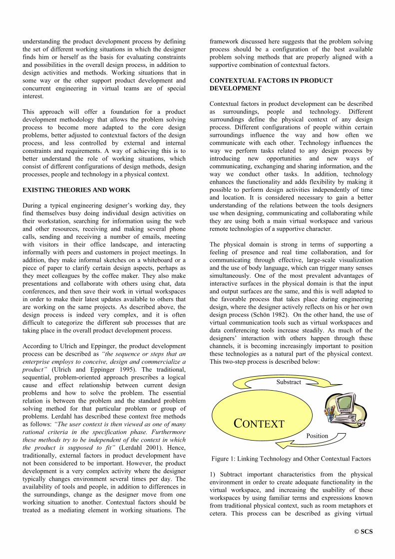
© SCS
understanding the product development process by defining the set of different working situations in which the designer finds him or herself as the basis for evaluating constraints and possibilities in the overall design process, in addition to design activities and methods. Working situations that in some way or the other support product development and concurrent engineering in virtual teams are of special interest. This approach will offer a foundation for a product development methodology that allows the problem solving process to become more adapted to the core design problems, better adjusted to contextual factors of the design process, and less controlled by external and internal constraints and requirements. A way of achieving this is to better understand the role of working situations, which consist of different configurations of design methods, design processes, people and technology in a physical context. EXISTING THEORIES AND WORK During a typical engineering designer’s working day, they find themselves busy doing individual design activities on their workstation, searching for information using the web and other resources, receiving and making several phone calls, sending and receiving a number of emails, meeting with visitors in their office landscape, and interacting informally with peers and customers in project meetings. In addition, they make informal sketches on a whiteboard or a piece of paper to clarify certain design aspects, perhaps as they meet colleagues by the coffee maker. They also make presentations and collaborate with others using chat, data conferences, and then save their work in virtual workspaces in order to make their latest updates available to others that are working on the same projects. As described above, the design process is indeed very complex, and it is often difficult to categorize the different sub processes that are taking place in the overall product development process. According to Ulrich and Eppinger, the product development process can be described as “the sequence or steps that an enterprise employs to conceive, design and commercialize a product” (Ulrich and Eppinger 1995). The traditional, sequential, problem-oriented approach prescribes a logical cause and effect relationship between current design problems and how to solve the problem. The essential relation is between the problem and the standard problem solving method for that particular problem or group of problems. Lerdahl has described these context free methods as follows: “The user context is then viewed as one of many rational criteria in the specification phase. Furthermore these methods try to be independent of the context in which the product is supposed to fit” (Lerdahl 2001). Hence, traditionally, external factors in product development have not been considered to be important. However, the product development is a very complex activity where the designer typically changes environment several times per day. The availability of tools and people, in addition to differences in the surroundings, change as the designer move from one working situation to another. Contextual factors should be treated as a mediating element in working situations. The
framework discussed here suggests that the problem solving process should be a configuration of the best available problem solving methods that are properly aligned with a supportive combination of contextual factors. CONTEXTUAL FACTORS IN PRODUCT DEVELOPMENT Contextual factors in product development can be described as surroundings, people and technology. Different surroundings define the physical context of any design process. Different configurations of people within certain surroundings influence the way and how often we communicate with each other. Technology influences the way we perform tasks related to any design process by introducing new opportunities and new ways of communicating, exchanging and sharing information, and the way we conduct other tasks. In addition, technology enhances the functionality and adds flexibility by making it possible to perform design activities independently of time and location. It is considered necessary to gain a better understanding of the relations between the tools designers use when designing, communicating and collaborating while they are using both a main virtual workspace and various remote technologies of a supportive character. The physical domain is strong in terms of supporting a feeling of presence and real time collaboration, and for communicating through effective, large-scale visualization and the use of body language, which can trigger many senses simultaneously. One of the most prevalent advantages of interactive surfaces in the physical domain is that the input and output surfaces are the same, and this is well adapted to the favorable process that takes place during engineering design, where the designer actively reflects on his or her own design process (Schön 1982). On the other hand, the use of virtual communication tools such as virtual workspaces and data conferencing tools increase steadily. As much of the designers’ interaction with others happen through these channels, it is becoming increasingly important to position these technologies as a natural part of the physical context. This two-step process is described below:
Figure 1: Linking Technology and Other Contextual Factors
1) Subtract important characteristics from the physical environment in order to create adequate functionality in the virtual workspace, and increasing the usability of these workspaces by using familiar terms and expressions known from traditional physical context, such as room metaphors et cetera. This process can be described as giving virtual
CONTEXT
Substract
Position

© SCS
workspaces physical characteristics, and this process has been in progress for quite some time, as recent virtual workspaces usually come bundled with a wide variety of different tools. 2) Effectively position the virtual workspaces in the right context, and understanding the relations between the virtual workspaces and the environment they are operating in, or the designer interaction space. In particular, this can be accomplished by making use of technologies with combined characteristics, such as digital whiteboards that combine excellent visualization characteristics with virtual characteristics, such as the ability to share information effectively over distance, et cetera. The physical domain is defined by the surroundings and other aspects of the physical context that encompass engineering designers. These are placed in the physical domain because of their distinct physical characteristics, by representing physical artifacts. Interactive surfaces in the physical interaction space, such as drawing surfaces (blackboards, whiteboards, paper, etc.) are of special interest, since these represent the points where engineering designers interact with their surroundings using pre-described, accepted methods. Acknowledging the importance of understanding the designer interaction space is a key factor enabling the transition from physically co-located design work to effective design as performed by teams organized virtually. Improved design effectiveness and efficiency is the outcome of understanding and learning to master the opportunities prevalent in the interaction space of the designer, and understanding the role of virtual, collaborative workspaces in the context of the interaction space. The designer interaction space thus describes the system of physical context and virtual communication and collaboration components the designer interacts with, either by interaction through physical presence or through various virtual means of communication and collaboration. WORKING SITUATIONS Working situations describes the configuration of design methods and activities, design process, and contextual factors. These are all interrelated. Working situations occur within the framework of the designer’s interaction space. Different working processes typically have different key configuration characteristics, based on external constraints and requirements and individual problem solving preferences, in addition to those introduced by the contextual factors people, technology and surroundings, which define the context of any given task-oriented working process. The Complexity of Working Situations Working situations are very complex of nature. The complexity of working situations is indicated in Table 1. In this table a small excerpt of the configuration variables surroundings, people, technology, process, and activities, is shown. Any configuration of these that is internally
consistent defines a unique working situation. Hence, any changes in any of the configuration variables will inherently lead to a new working situation.
Table 1: The Complexity of Working Situations Design Context: Surroundings
Office Design studio
Meeting room
Informal zones
Travel Home
Design Context: People
Team of One
Co-located (small to medium)
Co-located (medium to large)
Co-located with remote member
Mix of co-located & distributed
Fully distributed team
Design Context: Technology
CAD, CAE
Digital whiteboard
Telephone (mobile)
Virtual workspace
Data conferencing
Mail & messaging
Design Process
Detailed modeling
Concept generation
Analysis and evaluation
Information sharing
Decision making
Transfer of experience
Design Methods / Activities
QFD TRIZ Synectics Brainstorming Morphological Box
Value Analysis
Efficient Use of Working Situations A new approach is proposed that is based on the use of working situations as the main perspective where surroundings, people, technology and design tasks are considered a part of the same, holistic framework, and where the significance of contextual factors are acknowledged and emphasized. Important aspects of this approach include gaining an understanding of how to make effective use of the visualization potential in active and passive spaces, how to act in accordance with people and their presence, and how to create atmospheres that support creativity and decision-making through motivation. This leads to a new perspective proposing a situation-based design where the designer actively reflects upon the different design situations he or she is exposed to. Identifying and Configuring Working Situations A working situation is here described as an outcome of a configuration process, where the goal is the input and the configuration process a means to achieve a favorable working situation. This is adapted to the goals, by providing appropriate design methods and a suitable design process, backed up by a supportive context consisting of a well balanced configuration of people, surroundings and technology. When configuring working situations, the point of entry for the designer should be the goal, or what he or she wants to accomplish. This provides guidance to the design methods, the overall design process, and contextual factors. The type of process the designer is facing, whether this is concept generation, evaluation, structural analysis, decision making or any other kind, is related to both contextual factors, the overall goal, and the specific activities he or she engages in. The designer should then move on to identify possible configurations of surroundings, people and technology he or she could choose from that would provide adequate support for the process he or she is about to engage in, and then

© SCS
select the most appropriate configuration. The configuration variables of working situations are shown in Figure 2.
Figure 2: Working Situations, Conceptual Framework
CASE STUDY A series of case studies in graduate course SIO2043 Machine Design and Mechatronics at Department of Machine Design and Materials Technology at NTNU (Fyhn et. al. 2001, Hildre et. al. 2000), showed that there were differences in how product development activities were carried out, depending on the working situation. Special attention was paid to contextual factors in concurrent engineering. In one of the case studies, half of the student groups were physically co-located, and the others were organized virtually, communicating through the use of data conferencing (using MS NetMeeting) and email. All the different stages in the overall product development process were observed, but special attention was paid to the creative processes, concept generation in particular. Concept generation is a very creative activity that depends on the concept of flow (Fyhn et. al. 2001). This process requires a working situation that supports this kind of activity. Co-located Groups In the co-located groups, the students developed concepts using PAD-techniques (Ottoson 1998), while using body language to explain and discuss ideas. The contextual configuration supported a strong feeling of presence and close collaboration. Furthermore, being co-located created an atmosphere, which supported flow. In addition, the tools in use were perceived as being transparent for the students, there were few obstacles, using them did not obstruct the flow in the creative processes. Finally, the paper-based sketches were perceived as being personal, with a strong ownership. The students in general neither drew nor wrote on each other’s sketches. Instead, they made new sketches incorporating combined ideas from the group. All work had to be scanned in order to make it available to anyone, anytime. Virtual Groups In the virtual groups, the lack of body language, lower feel of presence and other aspects of altered contextual configuration changed the design methods in use as well as the design process. The design methods changed as the
distributed team configuration required use of different tools to contribute to the product development process by communicating, or by making sketches or comments. The case study indicated that the virtual team configuration to some extent was inferior to the co-located team setting in terms of creating an atmosphere for close collaboration. In addition, the technology used by the students was not perceived as being transparent due to many technical problems. The students could often feel that the tools in use obstructed the flow in the creative processes. However, other interesting aspects were observed as well. The virtual medium used for collaboration over distance was to a much greater extent than the paper-based media perceived as being a shared medium where the students could build on each other’s drawings and ideas. There was a tendency that the working situations were adapted to fit the goals over time. At first, the teams were confused by the new, imposed working situation where they had to collaborate over distance, but they gradually learned how to master this situation. Although slow at first, the ability to make necessary adjustments in the working situations eventually improved the efficiency of the design process, as the students discovered ways to make these adjustments. FINDINGS In these case studies, there were strong indications that contextual factors and the way these were configured had a significant impact on both the overall design process, the design methods, and the activities the student were engaged in. The team configuration influenced the tools in use, which in turn affected both the overall design process and the different design activities. Among the criteria that were observed, achieving a feeling of presence and close collaboration were important for the students. A team of designers needs a framework in which they can express opinions and excitement. Hence, the use of body language is important. For this process, adapting the working situation so that the contextual configuration supports the various activities taking place in the process is very important. To ensure a smooth process, it is important to make the technology as transparent as possible so that the creative process is not hampered. The surroundings, or physical environment, should be equipped with technology with required functionality. To some extent one can say that the virtual groups lacked contextual support. Hence there is a need to establish strong links between the technology in use and the context in which the technology is in use, as described earlier, in Figure 1. It seems like the most common basis for choosing setting is habitual practice, one chooses between a set of “standard solutions” where one feels experienced. These standard solutions often represent only a fraction of the available contextual configurations. Hence, designers often get “stuck” in the wrong working situation, or there is often a lag between the change of process and the necessary adjustments in the working situation. However, over time the standard
Design Methods
Contextual Factors
Design Process
Goal
Working Situation

© SCS
solutions are slowly adapted to fit the problems better, in particular in terms of providing better contextual support for the design process. CONCLUSIONS Describing the design process through a set of working situations describes an approach for designing based on an notion that designers are present in a physical context, and that different configurations of surroundings, people and technologies can be adapted to different design methods and activities, besides providing contextual support for different design processes. These configurations each define a distinct working situation that is unique and has its own characteristics in terms of modes of communication and collaboration. The great selection of possible configurations should be used as a means to ensure better contextual support for design processes, methods and activities, which will allow the problem solving process to be better aligned with the problem setting, by taking contextual factors into consideration. A series of case studies has shown that there are clear indications that an increased awareness of the role of working situations in product development will improve the utilization of the principles of concurrent engineering. This is particularly important for working situations dominated by real time collaboration. In order to make use of configuration of working situation as a design tool, there is a need to make contextual factors tangible and for reaching a deeper understanding of how contextual factors relate to the design process and the design problem itself. Once this is established, the reflective designer can become capable of monitoring his or her own design activities in such a way that a feed forward approach is made feasible. This can be described as “The best working situation is always the next”, where the designer actively navigates through different working situations instead of drifting between them, which is the logical outcome of not taking contextual factors into consideration. FURTHER RESEARCH Suggestions for further research include defining a framework where the contextual factors are made tangible. There is also a need to establish a set of criteria, which can serve as guidelines for configuring working situations. Combined, it is then possible to make tools and methods for configuring suitable working situations as a function of goals and available activities, processes, and contextual configurations. Furthermore the dynamics of working situations should be explored, in order to understand the transition mechanisms between different working situations and how to avoid the lag or delay between the point where the working situation does not provide sufficient contextual support, and the point
where the designer discovers this, and decides to make the necessary adjustments by configuring a new working situation. It would also be useful to explore tools, methods and technologies that can assist the transitions between different working situations, making it easier to move a product development process from one working situation to another, without losing momentum. REFERENCES
Ferguson, E. 1992. “Engineering and the Mind’s Eye.” The MIT Press, Cambridge, MA.
Fyhn, H.; Kristensen, K.; Hildre, H. P.; et al. 2001. “Produktutvikling i det virtuelle rom.” Research Report, Department of Machine Design and Materials Technology, NTNU, Trondheim, Norway.
Groth, L. 1999. “Future Organizational Design, The Scope for the IT-based Enterprise.” Wiley Series in Information Systems, John Wiley & Sons, Ltd., Chichester, UK.
Hildre, H. P.; Feilberg, J.; Fyhn, H.; et al. 2000. “IKT i læring.” Research Report, Department of Machine Design and Materials Technology, NTNU, Trondheim, Norway.
Hildre, H. P. 1998. “Corporate universities and new opportunities for academic institutions,” Workshop on Learning, Stanford University, Stanford, CA.
Hildre, H. P. 1998. “Challenges and new roles for engineering universities,” Workshop on Learning, Stanford University, Stanford, CA.
Kristensen, K. 2001. “Developing Methods for Developing New Methods of Improving Design Productivity by Focusing on Transitions Between Working Situations.” In Proceedings of the 2001 ASME IMEC&E, Vol. 2. ASME, New York, NY
Lerdahl, E. 2001. “Staging for Creative Collaboration in Design Teams.” Doctoral Thesis, NTNU, Trondheim, Norway.
Levin, M. 1997. “Technology transfer is organizational development: an Investigation into the relationship between technology transfer and organizational change.” International Journal of Technology Management, Vol.14, 297-308.
Maher, M. l. 1999. “Designing the Virtual Campus as a Virtual World.” In Proceedings of the CSCL 99 Conference. Stanford University, Stanford, CA.
Ottoson, S. 1998. “Qualified Product Concept Design Needs a Proper Combination of Pencil-aided Design and Model-aided Design Before Product Data Management.” Journal of Engineering Design. Vol.9, No.2, 107-119.
Schön, D. 1982. “The Reflective Practitioner.” Basic Books, New York, NY.
BIOGRAPHY KJETIL KRISTENSEN was born in Bærum, Norway. He received his graduate degree (sivilingeniør) from the Faculty of Mechanical Engineering at the Norwegian University of Science and Technology in March 2000, specializing in product development and distributed collaboration. He is currently pursuing a dr.ing. degree at the Department of Machine Design and Materials Technology at NTNU. He is also a co-founder of Boost Communications, a company offering SMS-based marketing tools and communication solutions for businesses and organizations.

TUTORING ACTIVITIES SUPPORTED BY ARTIFICIAL TUTORS
Filipe Martins Hélder Ribeiro Orlando Belo
Departamento de Informática Escola de Engenharia
Universidade do Minho Largo do Paço, 4700-320 Braga
PORTUGAL
KEYWORDS Agent-Based Computing, Artificial Tutors, Distributed Systems, Knowledge Engineering, Concurrent Engineering, Java Technology, Jini, and Jess. ABSTRACT Siesta is a distributed multi-agent system specially conceived to support e-learning activities in a conventional university environment. The system operates in a private intranet domain, providing on-line facilities for student evaluation and tutoring in multi-disciplinary domains, through conventional web browsers. Tutoring activities are supported by a specialized group of expert agents, the system tutors. These artificial tutors have the ability to follow students as they progress in the execution of a particular set of tasks, monitoring them or generating explanations about terms, concepts or other kind of requests necessary to the correct execution of an exam, a homework, or a laboratory test. This paper presents the design and implementation of the Siesta system, focusing on its functional architecture, agents, and interface platforms functionalities. INTRODUCTION Nowadays, it is not an unusual situation to find in a typical university environment teachers being solicited all the time to provide students with complementary information related to the scientific and technical areas that they usually study and learn inside classes. Additionally, they use also to require to teachers past exams, new or more advanced exercises, or simply some minutes more to discuss a particular case study. Some of them also expect to find teachers every time they need help in the execution of a particular task. Usually, teachers do not have the time they wish to satisfy all students' requests. They are frequently involved with management tasks, invited talks, or special tutoring activities, which systematically consume all the available time they have. Trying to attenuate this lack of attendance, teachers use to define special attendance periods exclusively dedicated to receive students and provide some additional tutorial support. But, in specific disciplines, with a large number of students,
these periods are clearly insufficient to surpass such kind of problems. Cases like these, specially the ones concerning with the availability of teachers to attend students and in the definition of additional studying plans and tutoring proposals, demand and justify the existence of special tools and structures to help teachers on such activities. The main goal of this work was to define and build a specific subject-oriented tutoring system with the ability to support students in scientific and technologic fields where they develop study activities and projects. The Intelligent Tutoring Systems (ITS) field (Murray 1999) (Chappell and Mitchell 1997) provides us the abilities to develop sophisticated software systems oriented to support and giving help in specific knowledge domain learning processes. Usually, an ITS presents means that students could use in the development of their own studying and knowledge acquisition models. Furthermore, an ITS also has the ability to follow students as they progress in the execution of a particular set of tasks, monitoring and correct them when necessary, or generate explanations about terms, concepts or other kind of requests during the study sessions. We believe that the integration of an ITS inside an university environment, accessed and used through an intranet infra-structure, will allows the improvement of student assistance, and attenuates in fact the effect of teachers' unavailability. An ITS can act as a private (artificial) tutor, with a high level of availability to attend students. Potentially, with the right operational conditions, students can use it 24 hours a day. Many are the examples of ITS projects and applications that we could easily found in scientific repositories, in the Internet, or in specialized literature (Pamela et al. 2001) (Viryou and Moundridou 2000) (Angehrn et al. 2001). Artificial tutors will be very important and useful tools, acting as complementary means to teachers' expertise and knowledge, since they have the ability to follow the evolution of the students in tutoring sessions, providing exams, quiz sessions, or simple exercise texts. In this paper we present a general overview of the implementation of an agent-based computer-aided tutoring system - the Siesta system -, approaching essentially all the aspects concerning its functional architecture, agents' classes and interaction models, user-system facilities, and system's data repositories.

THE SIESTA SYSTEM General Overview SIESTA is a distributed multi-agent system specially conceived to support e-learning activities in a conventional university environment. The system operates in a private intranet domain, providing on-line facilities for student evaluation and tutoring in multi-disciplinary domains through conventional web browsers. It provides specialized means to access and use remotely distinct repositories of evaluation and tutoring packages through conventional Internet browsers. System's tutoring activities are supported by a specialized group of expert agents, the system tutors. Searching, comparing, learning, and collaborating are typical tasks that agents can do on behalf of students, teachers and system's administrators. Spontaneously, they promote the division of tasks, according to their own expertise and knowledge, taking advantage of their abilities to cooperate and, consequently, conciliate all their independent efforts (Jennings and Wooldridge 2001) (Kinny and Georgeff 1997). The system does not intend to substitute a teacher or a human tutor, but it is a good complementary mean to follow and support students in specific areas of knowledge. It is a first attempt to reduce the effort of evaluation and teaching of large communities of students. Additionally, in case of an evaluation process the system is impartial and the results are more accurate that the ones obtained in a traditional way. In order to allow teachers and question makers to adjust future evaluation or studying sessions' parameters, the system stores all the data concerning topics, answers, questions, and explanations posed or required by students in specific decision support structures.
Figure 1: Siesta's Functional Architecture System's Architecture The system's main functional architecture (Figure 1) is organized into four distinct layers, namely: - Web Platforms, which represents the computational
platforms that support conventional browsers, providing access and granting services to system's users inside an intranet environment.
- Web Server, which is responsible to ensure and support the communication channels between the system's users and agents. It is built upon three main components:
Communication, that ensures the dialogue between the web browsers and the system; Web Services, a set of plugins integrated into the web server in order to make it parameterised and extensible - the extensions are typically Java Servlets; and the Data access, which is in charge to manage the connections between the Web Services component and the system's data repositories.
- Distributed Agent Platform, which provides the means and structures to receive and support the system's expert agents, whose main responsability is to decide what kind of questions and tutoring strategies should be selected.
- Data and Knowledge Repositories, which is responsible to provide data and decision support structures to tutoring and evaluation activities.
The distributed agent platform is the main system's component, due to its primer positioning in tutoring and evaluation activities. However, the servlet server, which attends requests and delivers them to the corresponding servlets, assume as well a major role in the global system functioning, since it maintains all the interaction processes between the system and the users. There are many advantages in using a component like this. It facilitates significantly the process of adding a new component or service to the system, or even to personalize any of the system's interface platforms. The servlets communicate with the system’s expert agents through a private communication medium - the distributed agent platform - using interface agents as communication service gateways. The communication medium is supported by Jini (Sun Microsystems 2001). System's agents use this medium to exchange messages among them and share data structures. The Agents Basically, the system integrates two classes of agents: interface and tutors. The former class is responsible to ensure a subject oriented communication platform between the web server and the tutors, providing facilities to present and evaluate the answers of the students during an exam, or during a presentation of a specific lesson. They also have the possibility to show the entire interaction history between users and the system, explain a particular inference path, or giving some help in the initial selection of an artificial tutor. They act as specialized gateways, granting the connection between the system's web services layer and the community of expert agents located in the distributed agent platform. The expert agents community constitutes the second class of agents - the tutors. As intelligent agents, with expertise and knowledge in specific domains, they have abilities to follow the students as they progress in the execution of a particular set of tasks, monitoring them or generating explanations about terms, concepts or other kind of requests necessary to the correct execution of the task - an exam, a homework, a laboratory test, or a simple studying session. An expert agent has the ability to supervise the students' working sessions accordingly to their system profiles and select the evaluation packages, deciding what kind of tutoring strategy it will apply in order to follow or evaluate the student's knowledge acquisition process. The expert agents are capable of interacting with each other, delivering control messages, status messages or data.
Intranet Environment
Jini Services
Data RepositoriesAccess Services
WebPlatforms
WP(1) WP(2) WP(n)
. . .
Web Server
DistributedAgentPlatform
Data Data Data. . .
Data Repositories
During the system sessions, tutors supervise the activities performed by students accordingly to their profile and the

selected evaluation or studying package, deciding, in real time, the "best" plan to apply the studying strategies improving student's knowledge and expertise. The content details of a question or a teaching action are determined by the strategies stored in the tutor’s knowledge base, which also stores a particular set of decision structures that allows the tutor to determine the appropriate teaching strategy. If a student select a session involving more than one tutor - a multidisciplinary session integrating several knowledge domains -, the tutors are able to promote cooperation among them, evaluating together the student session, exchanging data or results accordingly to the evaluation process requirements. Lessons and evaluation tests are presented in a conventional web browser using hypertext structures. Globally, two independent data repositories are responsible to provide data and decision support structures to maintain tutoring and evaluation activities performed by system's agents. They are: the online transaction processing unit, which is responsible to manage and store the necessary information to support all the evaluation and tutoring processes - questions and inter-related data (images, texts and others), and tutoring sessions information; and a tutoring and evaluation subject-oriented data warehouse, which keeps basically the information related to past processes, maintaining historical data that will be used later in the (re)definition of the student's profile. The Users The system allows the definition of three different user profiles: system administrators, knowledge domain administrators, and students. The former profile is exclusively used by system’s administrators to perform conventional maintenance tasks. The second one is the teachers’ profile, which provides them access to the system and supports all the services used to configure and set up the evaluation and tutoring activities. Finally, the student’s profile provides the means that students can use to access the system, in order to apply for a tutoring or evaluation session. Implementation Issues All system's components were developed in JAVA. The distributed agent environment was implemented in Jini and the expert agents' reasoning mechanisms in Jess. CONCLUSIONS AND FUTURE WORK The many applications that we find today in ITS fields show clearly the benefits that we can reach when using them in the support of tutoring and evaluation tasks. The integration of agent-based technology in this kind of systems it is not a new approach, having been used in several research and application efforts in the last years (Rickel and Johnson 2000) (Roda 2000). We believe that Siesta opens new perspectives in the support of tutoring and evaluation activities, namely in areas where it is required expertise and knowledge to deal with multidisciplinary problems. Additionally, it provides very flexible interface platforms, allowing system expansion to new student operational requirements without being necessary to develop special user interfaces or adapt the structures and functionalities of the system’s agents. The current version of the system must be
improved, in order to increase its efficiency and performance towards a more robust and efficient system. The coordination and cooperation models implemented must be refined and extended to receive new forms of inter-agent communication and information sharing. We also intend to create new forms of system interfacing based on mobile devices, such as PDAs or Web-PADs, providing to students the means to take with them a set of tutoring sessions, that will be latter appreciated by the corresponding expert agents. REFERENCES Angehrn, A., Nabeth, T., Razmerita, L., Roda, C., "K-InCA:
Using Artificial Agents for Helping People to Learn New Behaviours" Proc. IEEE International Conference on Advanced Learning Technologies (ICALT 2001), August, Madison USA, pp. 225-226, 2001.
Chappell, A., Mitchell, C., Intelligent Tutoring Systems for
'Trained Novices': Building Expertise in Mode Management, in Proceedings of the 1997 International Symposium on Aviation Psychology, Columbus. OH, 1997.
Kinny, D., Georgeff, M., Modelling and design of multi-
agent systems. In J. P. Muller, M. Wooldridge, and N. R. Jennings, editors, Intelligent Agents III (LNAI Volume 1193), pages 1-20. Springer-Verlag: Berlin, Germany, 1997.
Jennings, N., Wooldridge, M., Agent-Oriented Software
Engineering" in Handbook of Agent Technology (ed. J. Bradshaw) AAAI/MIT Press, 2001.
Murray, T., Authoring Intelligent Tutoring Systems: An
analysis of the state of the art, International Journal of Artificial Intelligence in Education, Vol. 10, pp. 98-129, 1999.
Pamela, J., Carolyn, R., VanLehn, K., Tools for Authoring
Tutorial Dialogue Knowledge, In Proceedings of AI in Education 2001 Conference, 2001.
Rickel, J., Johnson, L., Task-Oriented Collaboration with
Embodied Agents in Virtual Worlds. In J. Cassell, J. Sullivan, S. Prevost, and E. Churchill (Eds.), Embodied Conversational Agents. Boston: MIT Press, 2000.
Roda, C.., A multi-agent system for advising and monitoring
students navigating instructional Web sites" in Proc. 4th World Multiconference on Systemic, Cybernetics and Informatics (SCI 2000) and 6th International Conference of Information Systems Analysis and Synthesis (ISAS 2000) - Special session on Cooperative and Distant learning. July, Orlando Florida Vol.1 pp. 505-509, 2000.
Sun Microsystems, Jini Network Technology – An
Executive Overview, Sun Microsystems, Inc., 2001. Virvou, M., Moundridou, M. A Web-Based Authoring Tool
for Algebra-Related Intelligent Tutoring Systems, Educational Technology & Society, 3(2), 2000.

ENGINEERING A DMU-RESULTMANAGEMENT SYSTEM
Niko Kleiner Joachim HerbstUniversity of Ulm, Faculty for CS DaimlerChrysler, Research and Technology
89069 Ulm, Germany P.O. Box 2360, 89013 Ulm, [email protected] [email protected]
KEYWORDSSystem Development Process, Specification Languages,Workflow Management in CE, Practical Solutions, CaseStudies, Pilot Projects and Experiments
ABSTRACTRapid technological progress is responsible for continouslychanging IT-infrastuctures. This makes the introduction ofnew long term IT-solutions a difficult task. To handle soft-ware requirements for a new IT-tool we chose use cases,a software engineering technique for requirements docu-mentation, and adopted it to our specific needs. Use caseshave a number of well known weaknesses like feature in-teractions and early focus on human-machine interaction.We varied this technique by extracting commonalities andgiving additional context information. Further, we kept re-quirements descriptions abstract with respect to the con-crete software environments used by different developmentprojects. Our experiences were positive. The only disad-vantage of our approach was the effort needed to createstructured lists of requirements for management reports.
INTRODUCTIONOne of the main goals of the ECoS (Engineering of Co-operative Information Systems) group of DaimlerChryslercorporate research is the development of software engi-neering methods for cooperative information systems (DeMichelis et al., 1997). In a close cooperation with variousbusiness units of DaimlerChrysler these methods are ap-plied in a practical context, evaluated and improved. In thispaper we describe the application and evaluation of a usecase based requirements analysis and system evaluation fora DMU-resultmanagement system together with our part-ner from the Mercedes-Benz passenger car division.As the automotive industry is muving from a manual DMU(digital mock-up) process for collision and distance viola-tion checks to an automatic process, new IT-tools are re-quired. Automatic collision and distance violation checksproduce a huge number of results on a regular timely ba-sis. These results need to be inspected, evaluated, clas-sified and if necessary communicated to the engineers of
the conflicting parts. As there is usually only a small per-centage of changing results from one such check to the nextsucceeding check, not all of the produced results need tobe inspected. Hence, there is a need for an intelligent man-agement of those computation results to avoid unnecessaryre-inspection, -evaluation or -description.To optimize costs a unique strategic solution for result-management that satisfies the needs of all car developmentprojects should be developed to replace the local systems.What made this effort difficult is the rapid technologicalprogress. As a consequence, different car projects, whichof course have completely different target dates for the startof production, use slightly different IT-infrastructures notonly within the DMU-process. Hence, a software develop-ment method for such a long term solution must deal withthis continous change appropriately. This article describesexperiences of applying our software engineering methodto find, document and negotiate the requirements for sucha resultmanagement system and to identify a strategic so-lution for the DMU-process.
HANDLING SOFTWARE REQUIRE-MENTS
packing engineer result manager
«»
«»
import results
«»
«»
rate result
«»
«»
check solution
Figure 1: Use case diagram
To handle software requirements we chose use cases(Cockburn, 2001; Jacobson et al., 1994; Larman, 1997;RUP Development Team, 1999). Use Cases are a software

engineering technique to elicit, document and validate soft-ware requirements. They describe the tasks to be supportedby the software from a user’s point of view. In general, twotypes of documents are supported: a use case diagram, de-scribing the set of tasks under consideration, and use casedescriptions, a text document, that provides the detailed in-formation how each task will be executed with the supportof the future software system. A use case description isstructured into a short description, a precondition, a flowof events and a postcondition.Figure 1 shows an example: A use case diagram, heregiven in UML notation (OMG, 2001), consists of actors(‘packaging engineer’, ‘result manager’), use cases (‘im-port results’, ‘rate results’ and ‘check solution’) and rela-tions indicating what actor initiates what use case. An ac-tor represents a role that interacts with the software systemunder consideration. There are several extensions to thissimple notation. We refer the interested reader for furtherinformation to the literature given at the beginning of thissection.A use case description for ‘rate result’ may look like givenin Figure 2.
Use Case ‘rate result:’A specific result that has to be rated manually is searchedand rated.
Precondition:Most recent results imported.
Flow of events:– Result manager logs on.– The system provides the current list of results
to be rated manually.– Result manager chooses one of those.– He gets all attributes displayed.– He sets the rate based on this information.– The system stores this rate permanently.
Postcondition:The desired result has been rated.
Figure 2: Use case description
The flow of events is a detailed documentation of the in-teractions between the actor and the system they will gothrough in order to solve the task.Known ProblemsUse cases have experienced wide acceptance in the soft-ware engineering community. They are easy to understandby the future system’s user and provide good context in-formation where the requirements come from since therequirements are usually directly embedded into the flowof events, that is, in the user’s work sequence (Kulak and
Guiney, 2000). But also a number of difficulties with theirapplications have been reported.It is up to the software engineer to choose a level of ab-straction appropriate for such a description. Writing gooduse cases and including the right information without de-scribing too much detail is mainly based on personal ex-perience (Cockburn, 2001) and dependent on the applica-tion context. So, this technique can misguide the softwareengineer by drawing his attention too early on human-machnine interaction before understanding requirements.But, in the software development process, interaction de-sign is considered to be a step after requirements under-standing (Jackson, 1998; Kovitz, 1998).The above mentioned advantage that a use case descriptiongives a context for a requirement has also a downside. Thedrawback of this documentation technique is, that a sin-gle requirement, for instance ‘the resultmanagement sys-tem provides a standard query for all results to be ratedmanually’, can appear in many use cases. Changing this re-quirement at one place makes a complete review of all theother use case descriptions necessary in order to keep thedocumentation consistent. This phenomena is also knownas feature interaction (Jackson, 1998; Kovitz, 1998).The resultmanagement system has to be integrated into anexisting DMU process and an existing IT-infrastructure. Ause case is a single user single task view. Hence, there’sno possibility to express this embedding of the resultman-agement system. A common way of (partially) solvingthis problem is modeling surrounding components by ac-tors. But we also need descriptions of such componentsthemselves. For instance, there is the need to describe theexpected input format from the clash computing system.Based on this information, requirements for the import ofthis data into the resultmanagement software can be de-£ned. Further, the problem of describing the integrationinto the process remains.
Our ApproachTo address these problems, we varied use cases to betterfulfill our specific needs.We kept requirements descriptions abstract by chosing adescription level that is unspecific to the concrete softwareenvironment used by the different development projects.For instance, instead of talking about a specific clash com-puting software and describing technical file formats ofone or several such systems, that usually needs to be in-cluded in a requirements specification, we were only talk-ing about general aspects like necessary attributes of resultlists.Commonalites among different use cases were extractedand documented in seperate sections. The flow of eventsonly contained references. Many use cases needed stan-dard filters like ‘results sorted by part’ or ‘all parts that are

involved in a conflict’ etc. Such filters were documented ina seperate section and use case flow of events descriptionsused references to the filters needed. The same techniquewere applied for more detailed documentation of objectslike ‘result’ and their attributes.Finally, we gave an additional overview diagram to out-line the resultmanagement systems integration into the cur-rent infrastructure and process. Infrastructure descriptionscontain information about the IT components that feed theresultmanagement system with data (like the clash com-puting) and components that use the output for futher pro-cessing (like further handling of conflicting parts). This isan equivalent idea to the well known Structured Analysiscontext diagram (Yourdon, 1991). In addition, the DMUprocess steps that are supported by the resultmanagementsoftware are directly attached to this context diagram. Anexample is given in Figure 3.
clash computing
result management
problem tracking
«»
«»
check DMU
«»
«»
rate results
«»
«»
check solution
«»
«»
track problem/ solution
«»
«»
import results
Figure 3: IT-infrastructure and DMU-process context
The resultmanagement imports data (a result list) from theclash computing software and exports a subset of those re-sults to the problem tracking where a result is routed to theresponsible engineers. Beside the use cases of the diagramgiven in Figure 1 we list the DMU-process steps before andafter the resultmanagement and attach them to the softwarecomponents that support their execution.
APPLICATION RESULTSOur experiences with the selected software engineeringmethod were positive. The level of abstraction chosenfor the description of requirements enabled us to achievean agreement about the requirements very quickly. Com-parable projects required considerably more time for thistask. It turned out that one of the main challenges ofeffective requirements documentation and negotiation isfinding a level of abstraction that provides enough detailto talk about requirements in a concrete way but leavingout enough in order to avoid an early commitment to aspecific software solution. Those desicions should be post-poned until software implementation assignment. Further-more, the use case based requirements description made
the evaluation of requirements with the domain experts andthe evaluation of the software alternatives with the soft-ware providers very easy. The only disadvantage of theuse case based approach was the effort needed to create astructured list of requirements or an overview of the evalu-ation results of different software alternatives. Further im-provement can be done in the modeling and descriptionof IT-infrastructure and DMU process context information.This becomes more important when taking more than justresultmanagement into account. Possible extensions maybe based on Jackson’s work on problem frames (Jackson,2001).
ReferencesA. Cockburn. Writing Effective Use Cases. Addison-
Wesley Publishing, 2001.
G. De Michelis, E. Dubois, M. Jarke, F. Matthes, J. My-lopoulos, M. Papazoglou, K. Pohl, J. Schmidt, C. Woo,and E. Yu. Cooperative information systems: A mani-festo. Cooperative Information System: Trends and Di-rections, 1997.
M. Jackson. Software Requirements & Speci£cations:A Lexicon of Practice, Principles and Prejudices.Addison-Wesley Publishing, 1998.
M. Jackson. Problem Frames: Analysing and StructuringSoftware Development Problems. Addison-Wesley Pub-lishing, 2001.
I. Jacobson, M. Christerson, and P. Jonsson. Object-Oriented Software Engineering — A Use Case DrivenApproach. Addison-Wesley Publishing, 1994.
B.L. Kovitz. Practical Software Requirements: A Manualof Content and Style. Manning Publications, 1998.
D. Kulak and E. Guiney. Use Cases - Requirements inContext. Addision-Wesley Publishing, 2000.
C. Larman. Applying UML and Patterns. Prentice Hall,1997.
OMG. The uni£ed modeling language 1.4. Object Man-agement Group, 2001. www.omg.org/uml.
RUP Development Team. The rational uni£ed pro-cess 5.5. Rational Software Corporation, 1999.www.rational.com.
E. Yourdon. Modern Structured Analysis. Yourdon PressComputing Series, 1991.

EXTENDING CIM.OSA MODELLING FRAMEWORK TO e-ENTERPRISES
A.M.Stanescu1 , P. Antoniac2, P.Pulli2,M.Pallot3, P.Pascu1, I. Vasile1
1Politehnica University Bucharest, Human Resource Training Center, 132 Calea Grivitei., ,78122, Bucharest, Romania; e-mail: {ams,paul.pascu, vion}@utis.cpru.pub.ro
; 2University of Oulu, Department of Information Processing Sciences, Finland e-mail : [email protected] ;
3MP Consultants, Paris, France, e-mail : [email protected] ABSTRACT, The paper is an attempt to introduce a modelling framework for e-Enterprise new concept. Taking into account the high-level research to rafinate the CIM.OSA standard for enterprise integration, an extended 7x7x7 cube is proposed.Finally, the universitary pilot within University POLITEHNICA of Bucharest is in progress as a validation test. The common research work developed by the Concurrent Enterprising Network of Excellence (IST project no. 1999 – 29107) was a usefull informational groupware experience used for the present research. Keywords: Virtual Enterprise, Fabricator, eEnterprise, CIM.OSA 1. INTRODUCTION The various sintagmas used for different views of the new manufacturing paradigm are describing the global research effort focusing on the digital era challenge. The NGMS (Next Generation Manufacturing Systems) (Kosanke 1998), the ADMS (Advance Manufacturing Systems), (Fabian 1998), the DEE- Dynamic Extended Enterprise, (Browne 1998), the IMS -Intelligent Manufacturing Systems, (Brussel 1999) or the CE- Concurrent Enterprise, (Pallot 2000) are based on the new key-words: agile (Kidd 1994), holonic (Arai 1999), fractal (Bischoff 1998), bionic (Hatono 1999), virtual (Camarinha-Matos 2000). The new type of enterprises will have some new characteristic proprieties: autonomy, co-operation, virtual multidisciplinary team work, integrated approach for product-process-system design, re-thinking of humans position and role, they
will be agile as organisation and virtual as geographic distribution and alliance. An important requirement for all post-CIM manufacturing systems is the ability to capture knowledge from multiple disciplines and store it in a form that facilitates re-use, sharing, and extensibility. The manufacturing environment is typically seen as a large, complex, man-made system of heterogeneous, interrelated activities. Designers, planners, operators, schedulers are organisationally integrated within the collaborative ICT-based system. The convergence of disciplines involves real time control, embedded control, networking control (Metakides 2001), mobile communication (Antoniac 2001), multi-modelling and simulation driven design for complex socio technical systems. The important contribution brought into scientifically community attention by University Nova de Lisbon is concerned with an ICT support platform for Virtual Enterprise (VE). Considering a VE as a temporary and dynamic (i.e. with variable ”geometry”) organisation that appears in response to a business opportunity and disbanded on the completion of this business process (Camarinha 2000) a number of both base and auxiliary facilities&service can be identified. Potential partners' selection and negotiations agreements could be supported by the contract-net approach of the Distributed Information Management System. One of the important issues here is the identification of “who will perform this function” in this “democratic” value chain ( Katzy 2000). During operation of a VE, by Web interconnection among partners from e-commerce to points of sales and crossing all intermediate nodes: manufacturers and
1

distribution centres, there are some important goals to be achieved: the efficiency of orders flow, follow-up of orders evolution, management and exchange of order information among partners, distributed and dynamic scheduling, quality information even distance learning. It is the aim of the present paper to look beyond the virtual enterprise modelling framework. An attempt was planned for the debate during conference: “e-Enterprise is a powerful enough concept in comparison with VE?”. The author’s answer involves a general modelling framework : extended CIM.OSA cube. 2. FROM VIRTUAL ENTERPRISE TOWARDS e-ENTERPRISE Now-a days the "Virtual Enterprise" is for sure a hot research domain within Information Society horizon of hope. The closest "rival" term to VE is Extended Enterprise (EE) applied to "an organisation in which a dominant enterprise extends “boundaries” to all or some of its suppliers, where the VE can be seen as a more general concept including other types of organisations, namely a more democratic structure in which cooperation is peer to peer." [Camarinha,1999] One could stress on the idea that geographically distributed networked enterprises have a limited life cycle due to specific business duration. Each node has to perform a dedicated set of tasks, based on their core competence (Katzy 2000). This new type of organisation, VE, is faster reactive for facing the business process finite horizon opportunity better than well-known traditional organisations. The Virtual Enterprise involves: A business integrator, allowing both the
vertical and horizontally integration of SMEs, large companies (Santoro 1997);
A web community (concerning user friendly e- business approach for developing activity on electronic market place);
A multi-agent based internal co-ordinator, implementing Production Planning and Control (PP&C) within
wide-area-network of heterogeneous platforms;
An extended concurrent engineering oriented designer for product/ process / production system facilities .
There is no unique definition of VE, but a mosaik of definitions will permit us to underline some basic features, as follows Definition 1: The Virtual Enterprise is a temporary alliance of enterprises that came together to share skills and resources in order to attend a business opportunity and whose co-operation is supported by computer networks and adequate IT (Information Technology) tools and protocols . Definition 2: A Virtual Enterprise (VE) is a co-operative alliance often between entities with individually distinct legal identities which come together to exploit a particular business opportunity. Harnessing the power of working group technologies, the VE provides participants with a framework through which they can share the risks and returns, involved in bringing new products and services to market. [The Alive Project/ http://www.vive-ig.net/projects/alive.html] Advanced Legal Issues in Virtual Enterprise. Definition 3: The Virtual Enterprise is an open meta-system in a business universe where acts a set of Fabricators utilising multi-model representations of products/processes and co-operating in the framework of temporary alliances for achieving a set of goals (Curaj 1998):
VE = (U, F, Mv, G), where: U is an universe of discrete business
processes Note: The CIM-OSA methodology was the first to formalize business as a specific type of processes triggered by market requirements. F is the set of Fabricators (Stanescu
1997) The Fabricator is an autonomous agent
having a set of core competence (i.e. a set of functions that it is able to accomplish). A Fabricator could co-operate with other Fabricators with similar/ different core competencies by communicating goals and
2

data. By modifying its own performance evaluation measures according to a global goal and optimality criterion, a Fabricator defines itself as a fast-reactive component of a meta-system. Mv is the set of representations of
products/ processes/facilities depending on the type of Fabricators utilising them i.e. the set of multi-model representations (Stanescu 1997)
G is a structure of goal-type that is decomposable into a tree of objectives for every Fabricator implied in the VE meta-structure
As definitions underline, the main features of a VE are: the capacity of innovation; the capacity of co-operation; the capacity of internal reconfiguration; fast-reactivity; open system architecture compliant with
well - known standards (STEP, COBRA, EDI-FACT)
Despite this high-quality research work, a lot of traditional businessmen and industrial managers are facing circumspectiously the new “type” of enterprise. Keeping in author’s mind the various discussions about this concept, an attempt could be made to broaden the power of circulation by introducing a new concept: e-Enterprise. We are basically trying to “re-couple” the concepts of Virtual Enterprise and Real Enterprise. e-Enterprise is a socio-technical metasystem consisting of: • A set of product and/or services provider
along of business life cycle (product life cycle ) namely real Fabricators (rF)
• A set of functional entities involved in a role distributions to accomplish a business scenario (vE)
• An intelligent communication systems including enterprise collaboration system & others e-transport global platforms
• An e-business based web community created according legal issues negotiation among autonomous partners/organisational units.
Note: This e-E metasystem is fast reactive dispersed geographically organization acting on global market (aiming to be socked within
an e-marketplace). The main category of disturbances is due to turbulence of higher dynamic global market.
The web community of an eE uses a mosaic of the ICT to support multidisciplinary virtual teams activities like:
• Face to face meetings (team building tools, electronic decision tools, electronic copy boards)
• Cross distance meetings (audio video conference, screen sharing )
• On going coordination ( electronic mail, voice over IP, group editing, virtual project management/ scheduling)
The e-Transport platform is based on a well-balanced solution Intranet/Extranet //Internet, which must support collaboration software, knows as “GROUPWARE”. The recommended modelling framework extended CIMOSA cube, where the meta – language is XML/XSP.
The formal definition is the following quintuple:
e-E :{rF, (rP, rS), vE, webdt,C,G}. In 1985, the ESPRIT Consortium AMICE started to work on the definition and specification of a Computer Integrated Manufacturing (CIM) architecture for enterprise integration. - As a result the CIM.OSA is an ESPRIT
supported pre-normative development which provides a framework based on the system life cycle concept together with a modelling language and definitions of a methodology and supporting technology
Taking into account this richness of expertise for enterprise modeling the authors do believe that the most appropriate virtual enterprise modeling framework has to be the extended CIM.OSA cube.
However, some specific modification must be operated.
The CIM.OSA three orthogonal dimension could be preserved but they will receive different purposes.
(X) Instantiation of Building Blocks
(Y) Generation of Views (structural approach)
3
(Z) Derivation of Layers (architectural approach)

In comparison with the CIM.OSA modeling framework , the e-CIM.OSA 7x7x7 hypercube involves the following significance: Z
7) e-business e-commerce 6) e-services mobile communications 5) e-knowledge e-learning 4) e-management suply chain / customer relationship 3) e-design 2) e-logistic 1) e-manufacturing
Transport layer ( CSCW /ICS) Y
7) metasystem V.E. / E.E. / e-E 6) Systems 5) IT-based CAx DFx platform 4) Functional Applications (APIs) 3) Requirements modelling 2) Design specificiation model 1)Description of Implementation
Transport layer X
7) Goals / / benefic (busplan) 6) Activities (IDEF 1,2,5) Tasks (project management) 4) Resources(human, financial,capital, SW, H3) Knowledge knowledge base 2) Information(structuredata Data bases (relational, O1) Data (objects, entitie
Transport layer
As a first validation has been developedwithin the UniversBucharest
Based on Communication System which is described in [Cristea, Florea, Stanescu, 2000]; our universitary pilot consist of the following organizational actors: 3 Flexible Manufacturing Cells, 3km dispersed within the PUB campus, one of them Internet enabled cell (QNX – operating system) – providers ; 6 design laboratories (CATIA V4/V5 net) ;1 outsourcing DFMA ; 2 outsourcing Service Providers for modeling and optimization of manufacturing system (SIMAN-Arena and Enterprise Dynamics Taylor) ; 1 FMEA – (Failure Made and Effect Analyses) ; 1 ERP System laboratory (SAP-R/3) ; PDM system laboratory (Enovia) ; BPMS system (business process management ADONIS – BOC Gmbh) ;
e-management Supply Chain Management Customer Relationship Management Production Planning & Control Platform
Transaction Processing System Enterprise Collaboration System Process Control System Management Information System Decision Support System
Executive Information System
• Workflow Management System
• Product Data Management
• Process Planning System
Platform
iness
3,..)
W)
d
O) s)
test , a metasystem eE during last three years ity “POLITEHNICA”of
Executive Information System (SAS) ; Quality Function Deployment (SAS-QC) laboratory ; Process Planning System Laboratory
- A platform joining WfM. System & PDM system is planned to be supplemented this summer.
3 .CONCLUSIONS The paper has an attempt to introduce an extended modelling framework e-CIM.OSA for promoting the e-Enterprise concept. Some recent results for Virtual Enterprise conceptual design are also proposed for debate during conference. Finally, the collaborative e-Enterprise pilot within University POLITEHNICA of
Platform
4

Bucharest is described briefly. A special focus is developed to cluster research projects FABRICATOR & CoLaborator. This cluster is based on the idea that human resources, knowledge and creativity are the driving forces of the new generation of networked organisations (enterprises, laboratories, universities). REFERENCES
CAMARINHA-MATOS, L.L., AFSARMANESH 1999 “Tendencies and general requirements for Virtual Enterprse”In IFIP Conference “ Infrastructures for virtual Enterprises”, pp. 15-29, Kluwer Academic Publ,, Porto METAKIDES G. 2001 - Invited Conference in the 9th IFAC/IFORS/IMACS/IFIP Symposium on Large Scale Theory and Applications. Bucharest, Romania, July 18-20. ANTONIAC P., PULLI P. 2001– “MARISIL – Mobile user Interface Framework for Virtual Enterprise”. In : Proceedings of the 7th International Conference on Concurrent Engineering. Bremen, Germany, 27-29 June, pp. 171-180. ISBN 0-85358-098-7. PALLOT M., MAIGRET J-P, BOSWELL J., DE JONG E. 2000 – “ EPICE : Realising the Virtual Project Office”. In : Proceedings of the 6th International Conference on Concurrent Engineering. Toulouse, France 28-30 June, pp. 57-70. ISBN 0-9519759-9-4 CAMARINHA-MATOS L.M., AFSARMANESH H. 2000 – “The Virtual Enterprise Concept” . In : Infrastructures for Virtual Enterprises. Networking Industrial Enterprises”. Edited by : Luis M. Camarinha-Matos and Hamideh Afsarmanesh. Kluwer Academic Press, pp. 3-14. ISBN 0-7923-8639-6 KATZY B. R. 2000 – „The Value System Designer – An Infrastructure for Building the Virtual Enterprise”. In : Infrastructures for Virtual Enterprises. Networking Industrial Enterprises”. Edited by : Luis M. Camarinha-Matos
and Hamideh Afsarmanesh. Kluwer Academic Press, pp. 409-420. ISBN 0- STANESCU A.M, CRISTEA V, FLOREA A, CURAJ A. 2000, “Cluster Projects to Promote Concurrent Enterprising Paradigm”, Proceedings of the 6th International Conference on Concurrent Enterprising, Toulouse, France, 28-30 June, ISBN 0-9519759-9-4 CURAJ A. 1998, Ph.D. Thesis “Control of Manufacturing Systems integrated in Virtual Enterprise Framework” Politehnica University of Bucharest KOSANKE K., NEIL J.C., VERDANAT F., ZELM M. 1998- „Enterprise Integration – International Consensus (EI-IC) EP 21859“. In : Proceeding of the Conference on Integration in Manufacturing, Göteborg, Sweden, 6-8 October, pp.233-243. ISBN 0926-9622 FABIAN M., LENNARTSON B., GULLANDER P., ANDRÉASSON S-A, ADLEMO A. 1998– “Chalmers Architecture and Methodology for Flexible Production – CHAMP” . In Proceeding of the Conference on Integration in Manufacturing, Göteborg, Sweden, 6-8 October, pp. 720-731. ISBN 0926-9622 BISCHOFF J. 1998 – “The Fractal Company – Success factors of a High-Performane Organisation”. In : Proceeding of the Conference on Integration in Manufacturing, Göteborg, Sweden, 6-8 October 1998, pp. 257-265. ISBN 0926-9622. SANTORO R. 1997 The Virtual Vertical Enterprise approach for SMEs. Proc.of the 4th International Conference on Concurrent Enterprising, Nottingham UK, pag.361-363. ISBN 0-951-9759-6X. STANESCU A.M., DUMITRACHE I., CURAJ A. 1997– “Multi-Mode based System Design within Virtual Factory synergetic Framework”. In : Proceedings of the 4th International Conference on Concurrent Engineering. Nottingham, UK, 8-10 October, pp. 173-183. ISBN 0-951-9759-6X. KIDD P.T. 1994 “ Agile manufacturing” Addison-Wesley Publishing Company
5

DESIGN OF AN INTEGRATED PRODUCT DEVELOPMENT – AN ACTIVITY AND INFORMATION-BASED APPROACH –
W. Eversheim, G. Schuh, D. Assmus, L. Paulukuhn, J. Schröder
Laboratory for Machine Tools and Production Engineering (WZL) Aachen University of Technology
Steinbachstrasse 53, 52074 Aachen, Germany Phone: +49.241.80-27404
Fax: +49.241.80-22293 Email: [email protected]
KEYWORDS Integrated Product Development, Product and Process Model, Methods Database ABSTRACT Within this article an integrated approach to organize development processes on basis of activities and information flows will be presented. To support integrated product and process development several aspects have to be taken into account simultaneously: data and information management, process structuring and supporting methods. Within the Collaborative Research Centre 361 “Models and Methods for an Integrated Design of Products and Processes” an integrated approach has been developed to handle these aspects. For the management of data and information a generic integrated product and process model (IPPM) has been developed. Using this generic process model enterprise specific reference processes can be instantiated. Supporting methods and tools are associated in a methods database and linked with corresponding process steps. Within a case study of industrial applications the potential of the presented approach will be demonstrated. INTRODUCTION The development of innovative products which are in line with customer requirements and technological changes is one precondition for sustainable competitiveness. In this context, an efficient product and process development is one of the most important key factors. Therefore the Laboratory for Machine Tools and Production Engineering (WZL) developed an integrated approach to organize development processes on basis of activities and information flow. The approach is one result of the Collaborative Research Centre 361 “Models and Methods for an Integrated Design of Products and Processes” (sponsored by Deutsche Forschungsgemeinschaft) at the RWTH Aachen (SFB 361). This Collaborative Research Centre is an interdisciplinary research project of 13 institutes and chairs from the engineering as well as business administration faculty. The objective of this collaboration is the development of models, methods and tools which allow a market and customer focused parallel and integrated design of products, processes and services. The development process has to be supported
methodologically from the first product idea till the layout of necessary production means. To support these complex overall tasks both, a continuous process and product data model as well as supporting methods are necessary. MODELS FOR THE INTEGRATED PRODUCT AND PROCESS DESIGN An integrated product and process model (IPPM) has been developed to ensure the representation, integration and distribution of data and information for an integrated design of products and processes. The IPPM is an object oriented generic model. To ensure extensibility and transparency the IPPM is build modularly. It consists of 34 schemata. The formal representation has been realized in the data modelling language EXPRESS and its graphical subset EXPRESS-G. The IPPM encompasses data and information of all product life cycle phases, whereas the provision of data and information focuses on product and process development. With its contents and functionality the IPPM is the basis of conceptual and IT integration inside the Collaborative Research Centre 361 (Collaborative Research Centre 361 2002). Core of the IPPM is the product model and the process model. They are connected by the meta information model. Further components are the resource model, the life cycle model and the assessment model. The resource model represents data about resources like staff, organization, materials and production facilities. Information about life cycle, i.e. life cycle phase, is stored in the life cycle schema. Information that is necessary for assessment of activities, status of activities and components are stored in the assessment model. Project example of the Collaborative Research Centre 361 is the development of a wind turbine. The generic schemata of the IPPM are instantiated i.e. with the project structure elements, processes, resources and methods of this specific project. The general structure of the IPPM is displayed in Figure 1. In the following the instantiation will be demonstrated by the example of the process scheme. The process scheme supports modelling process structures and process networks (Eversheim, Westekemper 2001). It allows also the representation of uncertain processes. Core of the process scheme is the activity element (Figure 2). An activity is an activity group, a generic activity, a specific activity or an individual activity, where an activity group consists of one

or more generic activities. Activities reference on resources, time, objectives, organization, components, and characteristics. The data is stored in referenced schemes. Activities might have preceding and following activities.
Figure 1: Structure of the IPPM
Figure 2: Process scheme In Figure 3 two views on the instantiated process model are displayed. The project plan shows the activity group technology planning as well as the activities brainstorming for alternative product concepts and checking the technical feasibility. The activities are related to components of the product structure. The concrete product structure is shown in the upper part of Figure 3. The user interface is realised as an Engineering Data Management System.
product structure (excerpt)
project plan (excerpt)
reference model
inst
ance
s
life cycle model
integrated product- and process model
assessment model
metainformation
model
productmodel
resource model
processmodel
productstructureelementsprocessesresourcesmethods
project example
models methods
prototypesexample
reference model
inst
ance
s
life cycle model
integrated product- and process model
assessment model
metainformation
model
productmodel
resource model
processmodel
productstructureelementsprocessesresourcesmethods
project example
models methods
prototypesexample
Figure 3: IPPM instances
METHODS FOR THE INTEGRATED PRODUCT AND PROCESS DESIGN Within the Collaborative Research Centre (SFB) 361 more than 80 methods and tools to support integrated design of products and processes have been developed. These methods cover the whole product development process from systematic monitoring of customer and market demands, internal and external project management, and technology management to production planning. To manage and integrate the multitude of methods - internally as well as externally - in an efficient way, a method data base has been implemented. The methods database needs to meet the requirements of two different user groups. For the researcher of the Collaborative Research Centre 361 it is most important to place and find all relevant information concerning the method development. Otherwise, potential industrial users are mostly interested being supported in method application. Taken into account these requirements a WWW-based methods database has been developed and implemented. All methods developed in the SFB 361 are stored in the methods data base. The data base contains a short and an extended description for every method. Further information is provided through hyperlinks on decentral Internet-pages (Figure 4).

identifyingkey words
generatedinformati
Figure 4: Methods Database - layout and functionalities
To visualize the interdependency of the methods the black-box-principle has been used (Figure 5). The methods are considered as information processing black-boxes with needed input and generated output information. Within the database every input and output information is linked via hyperlink to the generating (prior) respectively using (successive) methods. Thus, the integration and networking of the methods can be visualized by navigating through the methods landscape.
input-output per task per method linkage of methods
method 1
method 3
method 5
method 2
method 4
method n
method 1input output
Methode 2Input Output
Methode nInput Output
task A ...
Methode 1Input Output
Methode 2Input Output
Methode nInput Output
task A2
method 1input output
method 2input output
method ninput output
task A1
methoddatabase
n
Figure 5: Black-box-approach
To identify problem specific methods to support a certain process step or task different search functionalities have been implemented: full string search, key word list and input-output-search. The input-output-information search supports identifying methods which use certain information as input or generate certain information as output. The input and output interfaces to place and present the methods are predefined to a certain level. This ensures a consistent appearance and therefore a higher level of user acceptance. Leaving the methods database by hyperlinks to detailed method descriptions on decentral servers every author (= user who has placed a method into the database) is free in the style of presenting these comprehensive information. The methods database is realized on a SQL-Server, connected via ColdFusion Middleware with a WWW-Interface (Figure 6). Therefore, potential users can work with database with standard WWW-Browser nearly independently of the used data operating system. All functionalities of the methods database are protected with a firewall and user-individual passwords.
Currently, the methods data base is extended by existing standard product development methods. Additionally, the application of multimedia techniques for the targeted, user friendly support of method application will be realized.
title ofmethod
organisationaldata
short
Methods database
Cold Fusion
WWW-Interface
SQL-Server
plattform-independent
access
problem specificsearch algorithms
consistentappearance
linkage ofmethods
decentraldetailed
information
neutralmethod
description
central shortand extended
description
descriptionextended
description
link toedp-tool require
informationon
Figure 6: Methods Database – structure and characteristics
ENTERPRISE-SPECIFIC SOLUTIONS ON BASIS OF ACTIVITIES AND INFORMATION FLOWS To transfer the presented research results to industrial application several steps have to be passed through: First of all, using the generic process model branch or enterprise specific reference processes have to be instantiated. Activities of development processes are analyzed concerning their input and output information as well as the information flow. Additionally, weak points are identified and removed by reorganizing the process. Afterwards, every single process step has to be associated with supporting methods and tools. Therefore, in the IPPM predefined process – method links can be used. Additionally, a trade or enterprise specific product model has to be instantiated (Eversheim 2001a, Eversheim 2001b). In the following the intranet based software tool “e-FESTOS”, connecting both, the reference process model with the methods database, will be presented. CASE STUDY: SOFTWARE TOOL “e-FESTOS” Combining standard internet technologies e-FESTOS offers the opportunity to provide product developers with all the enterprise-specific information needed for an efficient and successful design process. Build as a server application e-FESTOS can be accessed with every standard WWW-Browser so that no special client software is necessary. Four different perspectives on the design process are implemented in e-FESTOS. On the one hand the user needs to be informed about all mandatory tasks that have to be passed through during the design process, where it is of vital importance to provide a view on all preceding, parallel and following process steps. Thus interfaces to parallel task can be identified and an opportunity to optimize the collaboration between different resorts is provided. For that reason e-FESTOS displays a browseable and graphical depiction of all process steps, always showing all preceding and following process steps. Secondly, e-FESTOS also offers an organization chart, where all employees are

hierarchically stored. Responsibilities and participations are assigned to every process step via hyperlink so that a list of all tasks for a certain employee can be generated. This general assignment creates clarity and also helps optimizing a necessary collaboration. Furthermore, methods and tools can be assigned to every process step. By that way it is ensured that always a concrete selection of applicable methods is delivered. Finally, templates needed in a specific process step can be deposited. Passing a process step the developer can download all necessary templates, e.g. for reports, documentations etc. On the basis of a corporate project of Nordex and the WZL the principal approach for the implementation of e-FESTOS is demonstrated. The Nordex Group is one of the world’s leading suppliers of wind turbines, with a focus on units with a high capacity. With the N80/2500 kW Nordex offers the largest serial produced wind turbine in the world (N.N. 2002). The core competencies of Nordex are the overall technical design, the development of rotor blades with a length of up to 45 meters and in the integrated electrical and control technology for wind turbines. The Nordex Group with its three 100 per cent subsidiaries Nordex Energy GmbH, Südwind Energy GmbH and NPV Planung & Vertrieb GmbH employs a workforce of about 750 - continuously growing - achieving revenues of about 350 million euros a year. Starting with an analysis of existing processes a process re-engineering is carried out. Based on the experiences gathered in the Collaborative Research Centre (SFB) 361 the reference process is instantiated and optimized concerning a high degree of parallelization and a general information flow. Clear responsibilities and participating departments are identified and assigned to the process steps. All methods from the methods database are filtered so that a maximum of suitable methods can be provided for every single process step. Finally, the documentation templates are prepared. Due to the fact that the e-FESTOS tool is equipped with a so called “content-management-system” the knowledge of HTML-programming or similar for the administrator of the tool is obsolete. User-friendly all information can be stored via a graphical user interface. Even the graphical depiction of the process is generated in this way. Later changes to the contents are also implemented as described, so all information can be easily kept up to date. After storing all information the system is immediately ready for use. ACKNOWLEDGEMENTS The presented results have been developed within the Collaborative Research Centre SFB 361 “Models and Methods for an Integrated Design of Products and Processes” funded by the Deutsche Forschungsgemeinschaft (DFG).
CONCLUSION The results of the Collaborative Research Centre 361 represent the platform for a reengineering of development organizations. The approach on basis of activities and information flows ensures an efficient design of development processes as well as IT-tools and method application. Transparency of processes is guarantied by implementation of processes and documents in the intranet-based tool e-FESTOS. REFERENCES Collaborative Research Center 361. 2002. “Models and Methods
for an Integrated Design of Products and Processes”, University of Technology Aachen, Internet: http://www.sfb361.rwth-aachen.de
Eversheim, W.; M. Westekemper. 2001. ”Integriertes Produkt- und Prozessmodell des Sonderforschungsbereichs 361.” ProduktDaten Journal. No. 2. November 2001.
Eversheim, W.; T. Bauernhansl; and J. Schröder. 2001a. „Intranet-based Management of Product Development Processes“. Proceedings of the International CIRP Design Seminar – Design in the new Economy. Stockholm, Sweden, June 6th-8th 2001.
Eversheim, W.; C. Voigtländer; T. Bauernhansl; and J. Schröder. 2001b. ”Intranet-basiertes Entwicklungsmanagement – der schnelle Weg zu neuen Produkten.” Konstruktion – Zeitschrift für Produktentwicklung. No. 5. May 2001.
N.N. 2002. Homepage Nordex AG, Internet: http://www.nordex-online.com/
BIOGRAPHY PROF. DR.-ING. DIPL.-WIRT. ING. DR. H.C. MULT. W. EVERSHEIM is Director of the Laboratory for Machine Tools and Production Engineering (WZL) and holder of the Chair for Production Engineering, Aachen University of Technology since 1973. Since 1980 he is Director of the Fraunhofer Institute for Production Technology (IPT), Aachen. He is also Director of the Institute for Technology Management (ITM), University of St. Gallen (HSG), Switzerland, and Director of the Research Institute for Rationalization, Aachen University of Technology.
PROF. DR.-ING. DIPL.-WIRT. ING. G. SCHUH is Director of the Institute for Technology Management, University of St. Gallen (HSG), and Founder and President of the GPS Complexity Management Inc., Software and Consulting Company in St. Gallen, Aachen and Atlanta. Since October 2001 he is Professor at the Foundation Chair for “Production Engineering” at the Laboratory for Machine Tools and Production Engineering, Aachen University of Technology, and elected to follow Prof. Dr. Walter Eversheim as successor on the Chair of Production Engineering in September 2002. DIPL.-ING. D. ASSMUS, DIPL.-ING. L. PAULUKUHN and DIPL.-ING. J. SCHRÖDER are research assistants at the Chair for Production Engineering at the Laboratory for Machine Tools and Production Engineering, Aachen University of Technology.

NETWORKING AND
DISTRIBUTION IN CE


USING MPEG-4 IN THE ENGINEERING DOMAIN
Falk Dobermann and Uwe von Lukas Computer Graphics Center (ZGDV)
Joachim-Jungius-Str. 11 18059 Rostock, Germany
E-mail: [email protected]
KEYWORDS MPEG-4, CAD, Streaming, ASP, CSCW, Internet
ABSTRACT This article describes the current status of the m4CAD project. The project deals with application areas of the MPEG-4 standard in the engineering domain. Following a brief overview of the standard, different scenarios are presented, including CAD conferencing, Application Service Providing and multimedia product catalogues.
1 INTRODUCTION TO MPEG-4 Virtual Engineering scenarios frequently rely on internet technology, such as transmitting visual representations of 3D models over the network [Sen01]. Importing remote assemblies into a local DMU or discussing changes of a part in a virtual design conference are two examples in this context that can make use of MPEG-4 [BCL99] as a standard and technology for coding audio-visual objects. The MPEG-4 standard is specified by ISO/IEC 14496 [ISO00] and builds on three application areas: digital television, interactive graphics applications and interactive multimedia. Its aim is to establish a universal, efficient coding of different forms of audio-visual objects, within which objects can be natural - as in MPEG-1 and MPEG-2 - or synthetic. The standard itself is divided into six different Parts: - Part 1 Systems
This part defines the MPEG-4 terminal architecture. The decoder, synchronization, and buffer model is specified here. Additionally the BIFS scene and object description syntax and semantic is also defined in this part of the standard.
- Part 2 Visual In this part of the standard the decoding of visual object is defined. Various tools and profiles for different applications are specified.
- Part 3 Audio Audio decoding is defined in this part of the standard. As in the visual part various tools and profiles for different application scenarios are specified.
- Part 4 Conformance Testing In the fourth part of the standard sample bitstreams are provided to test MPEG-4 terminals.
- Part 5 Reference Software
In this part a sample implementation of the standard is provided including source code.
- Part 6 DMIF – Delivery Multimedia Information Framework This part defines the interface to use MPEG-4 with application specific transport mechanisms. It specifies an Interface for application programmers to implement storage or transport protocols for MPEG-4 delivery.
The important description of the MPEG-4 scene is defined by the BIFS (Binary Format for Scenes) language, which is based on the VRML graphics description language. BIFS differs from VRML in two major aspects. 1. The scene is described in binary1. 2. MPEG-4 Multimedia and Interaction functionality is
added in special graph nodes. Two interaction mechanisms are built into BIFS. Firstly, there is the VRML event system, which enables client-side interaction. Event sources are connected to event targets via a “ROUTE”. A possible application of this is the pushing of the button that sends an event. The event is then routed to a switch node, which changes the subgraph it displays accordingly. Another interaction scenario is introduced with amendment 1 to the systems part of standard 2. Here, an event is passed to the server by means of server-side interaction, and the server then has to react to the event with, for example, a change of scene. A BIFS scene is not static. It may be added, deleted or modified. It is also possibile to add Java script to enable more advanced dynamic behaviour. The most attractive features of MPEG-4 include: - Scene-based and object-oriented representation - New powerful Codec support and existing contents
integration - Script and language support for high interaction. - Transparent network interface - Streaming file format
1 A textual format based on XML is defined in Amendment 1 to the Systems Part of the Standard. This can be used for exchange with the X3D Web format, for example. 2 ISO/IEC 14496 Part 1 Amd. 1

MPEG-4 thus provides a sophisticated approach for streaming multimedia content in a very efficient manner. In covering 3D data, still images and video/audio, the standard supports all essential media in the development of diverse Internet solutions in the mechanical engineering domain. The following chapters present initial concepts of how to use this new standard in the field of Computer Supported Cooperative Work, Application Service Providing and multimedia product catalogues.
2 COOPERATIVE CAD WITH MPEG-4 Cooperative CAD uses methods of computer supported cooperative work (CSCW) to enable a group of users to work jointly on a constructive model. The problem with existing conference systems is the use of heterogeneous protocols for communication [Luk01]. Systems made by different manufacturers cannot work together, which means that users have to rely on the developer of the CSCW CAD system used. MPEG-4 could be applied to overcome this obstacle. The goal is to create an MPEG-4 based collaboration system for CAD. Such a system would enable any MPEG-4 Terminal to be used as a front-end to a CSCW CAD system. Users could utilise a wide variety of devices to access a CAD conference, i.e. 3G cell phones as well as MPEG-4 SetTop boxes, etc. As published in [Dob01], a rudimentary MPEG-4 collaborative CAD system was implemented based on the MPEG-4 reference software implementation. An MPEG-4 based collaboration system can be implemented by using an existing proprietary collaborative CAD system with open interfaces. This system can be extended so as to also enable it to bind with MPEG-4 terminals. This binding is achieved by a software component (MPEG-4 Transfer), which translates events and data of the CSCW CAD system to MPEG-4 and, in turn, translates events and data from the MPEG-4 terminals to events understood by the CSCW CAD system. For the CSCW CAD system, this software component is another front-end like any proprietary front-end. For the MPEG-4 terminals, the component is an ordinary MPEG-4 server, which communicates with the terminal via MPEG-4. The advantage of this approach is that MPEG-4 terminals and proprietary front-ends of the CSCW CAD system can be used synchronously in a conference. This makes it possible to combine the advantages of both solutions. To make CAD functionality available to the MPEG-4 user, a BIFS scene is modelled to realise the user interface of a CAD application in an MPEG-4 terminal. This comprises the following items: - The geometric model can be converted to MPEG-4
using 3D BIFS nodes or 3DMesh objects. - The user interface, including interaction elements and
status displays, can be realised using 2D BIFS nodes. A visual feedback can be provided to the user of the terminal by using ClientSide interaction.
- Interaction with the CSCW CAD application can be realised through ServerSide interaction.
Apart from CAD functionality, CSCW tools can be provided to support the joint work of the conference participants. This includes the following items: - With the telepointer tool, a conference participant can
watch the mouse pointer movements of other members of the working group. The mouse pointers of remote users can be displayed in the MPEG-4 terminal by modelling the pointer with 2D BIFS. The position of the telepointer on the terminal window is updated continuously.
- The history tool records communication during a CAD conference. When a new user logs into the conference, the recorded information is played by the history tool to bring the newly connected front-end up to date.
- With the WYSIWIS (What You See Is What I See) tool, all users observe the geometric model in the same way. Apart from the viewing transformation, this also includes the rendering attributes.
- This tool uses the abilities of MPEG-4 to code audio and video data to create an audiovisual conference. This conference can support the CAD conference by enhancing communication between the conference members.
- Digital Rights Management enables the different participants of a CAD conference to ensure that their rights on parts of the geometric model are adhered to. This makes inter-company collaboration possible.
3 APPLICATION SERVICE PROVIDING Application Service Providing (ASP) is a novel and promising approach to the distribution of software [LSW00, Luk02]. By changing the philosophy from software as a material good (e.g. CD-ROM) to software as a service, a number of benefits can result for the software vendor (reducing time to customer, development of new markets, etc.) and the end-user (concentrating on usage rather than installation and maintenance, pay per use, reducing total cost of ownership, etc.). In the engineering domain, on the other hand, we find several ancillary conditions that inhibit an ASP boom, as found in other areas such as customer relationship management. The tight integration of various applications (CAD, CAE, PDM) in the design process as well as the importance of high-end graphical presentation and interaction are just two of the important requirements that must be taken into account in this regard. Most of today’s solutions use display redirection to transfer the user interface from the host computer to the desktop (ref. fig. 1). However, this approach is not suitable for applications with advanced graphical interaction. The use of display redirection includes the necessity to transfer huge amounts of data over the network, which requires a broadband Internet connection. This is why interaction is especially slow, in graphical applications.

Input
Output
LocalComputer
RemoteServer
Applicationmodel
Presentationmodel
Pixel image
Backend
File
Frontend
Pixel imageInternet
Figure 1 - Display redirection for ASP
MPEG-4 can improve this situation. One possible solution for ASP via MPEG-4 utilises the tools defined in the MPEG-4 standard for delivering the application to the user, to protect intellectual property rights (proprietary extended by accounting and billing) and to represent 3D or 2D models. Compared with the technique of display redirection, the advantage of this approach is that representations of the model are locally available on the ASP customer side (ref. fig. 2). Interactions like changing the viewing parameters can therefore be executed locally without the ASP server. This together with the ability to code the representation of the model in MPEG-4 means that only a small bandwidth is needed in this scenario. While MPEG-4 is an official ISO standard aimed at multiple display devices, all MPEG-4 compatible terminals can be used by the ASP customer, e.g. ASP software could be used on MPEG-4 set-top boxes connected to a television screen or on 3G mobile devices.
Input
Output
LocalComputer
RemoteServer
Applicationmodel
Presentationmodel
Backend
File
Frontend
Pixel image
Internet Presentationmodel
Figure 2 - MPEG-4 based application delivery
The MPEG-4 data stream is generated by an MPEG-4 server at the ASP, where 2D or 3D models are encoded in MPEG-4 BIFS and streamed to the terminal. Interaction is possible solely on the terminal side or with the involvement of the server. In this case, these interaction events are received and processed by the server. The application of MPEG-4 for ASP is not very different to collaboration with MPEG-4, which means that solutions acquired with collaboration can be applied to ASP. It is even conceivable for the ASP costumer to be enabled to collaborate with other costumers.
4 MULTIMEDIA PRODUCT CATALOGUES Another attractive scenario for MPEG-4 in the engineering domain is the publication of multimedia product catalogues. A 2D or 3D representation of a model is encoded in MPEG-4 and enriched with metadata, which describe the properties of the model and gives purchasing information. The MPEG-4 representation of the model can be generated by a software module using the output of the CAD system (online or offline) as the data source. The metadata can be edited by a user derived from the CAD data or extracted from the CAD system. MPEG-4 enables interaction techniques products in the to be linked to an e-shopping system. The catalogue can use a rich set of tools to enhance the layout of the representation. The improvements to the presentation layout can be carried out in a post-processing step. Additional media can be embedded in addition to the design of the presentation. This includes the use of natural audio and video clips and synthetic MPEG-4 media. As a result, a file is generated in the MP4 file format, which can be given to potential customers on portable storage media (CD-ROM, DVD, etc.) or streamed over the Internet. Costumers can view the catalogue on any MPEG-4 compliant terminal device. In contrast to the many proprietary approaches available on the market, a standardised format, such as MPEG-4, offers various advantages: - Models of different sources can be merged without
additional conversion. - The user only needs an MPEG-4 terminal - no
additional software (plugin etc.) is necessary. - The rich support for multimedia allows for additional
audio and video in the product presentation. - A variety of MPEG-4 authoring tools and converters are
expected to come onto the market in 2002.
5 PROTOTYPE Our prototype demonstrates two of the scenarios refrerred to above: remote access to a CAD system as required within the context of ASP and a CAD conference where two or more users share a common model. The current implementation is based on the Reference Implementation available from ISO. The so-called Terminal Player3D has been extended to meet basic requirements for use in an MPEG-4 based CSCW-CAD scenario. This includes the implementation of missing node semantics as well as the implementation of the Amendment 1 syntax. A back-channel has been added to enable ServerSide interaction.

MPEG-4 Player Terminal
Composition & Rendering
Compression Layer
Sync Layer
DMIF Player Extension
MPEG-4 Transfer
CSCW CAD System
MP4Connect
MP4Compile
MP4Send
MPEG-4
Figure 3 - Architecture of the collaboration scenario
The Terminal has also been extended with a DMIF module to enable streaming of MPEG-4 data. The implementation uses the well-known HTTP to send MPEG-4 elementary streams. The implementation of the server is therefore realised in the form of an extension of the Microsoft WebServer IIS. The Internet Service API (ISAPI) is used to implement the MPEG-4 server DMIF. A different software component is used to encode the MPEG-4 data. The encoding process uses parts of the reference software to create an MPEG-4 representation. This component is used by another component, which translates MPEG-4 and proprietary events as well as data representations. The implementation uses the CORBA-based TOBACO CSCW CAD system [Luk97], which provides basic CAD and CSCW functionality. By changing the actual CORBA interface to the standardised CAD Services API of the Object Management Group, any CAD system that implements this interface could be used as a back-end system in the context of ASP. The CSCW features integrated in TOBACO are unique and are not part of today’s commercial CAD systems. The biggest problem regarding implementation is the terminal. The Player3D does not represent a complete implementation of the standard. Not all CSCW tools can be demonstrated (e.g. DRM and AV-Teleconference) and the interaction possibilities are limited. Furthermore, the stability of the software is not very satisfactory.
Figure 4 shows the MPEG-4 user interface displayed by the reference software terminal during a conference. The left area of the scene is occupied by a 2D elemt, where the buttons for creation and modification of solids can be triggered. The lower area is also 2D and is used for collaboration functionality (floor control, list of users etc.). The rest of the scene is 3D and presents the model from three different viewpoints. A telepointer is implemented as an 2D overlay that represents the local pointer of the remote partner.
6 FUTURE WORK Due to the problems with the terminal implementation, the most urgent future development will be to shift to a different
terminal. An optimum solution would include an MPEG-4 server with real-time BIFS-encoding capabilities. This solution would enable the developer of an MPEG-4 based CSCW CAD system to focus on the coupling of the CSCW CAD system. Other future issues concern the enhancement of interaction and the possibility of an orthogonal viewing transformation. Both can be achieved by extending BIFS with new nodes. The audiovisual teleconference can be implemented. The possibilities of MPEG-J in the context of collaborative CAD must be evaluated. Other issues include the use of Digital Rights Management and the effect of Quality of Service attributes of the communication to the conference. In the long-term, the research conducted in this project may also contribute to an MPEG-4 based solution for application service providing (ASP).
7 REFERENCES
[BCL99] Battista, S.; Casalino, F. and Lande, C.: “MPEG-4: A Multimedia Standard for the Third Millenium”, Part 1, IEEE Multimedia, pp. 74-93, Oct-Dec 1999.
[Dob01] Dobermann, F.; "Synchrone Telekooperation im CAD-Umfeld auf der Basis von MPEG-4", Diploma Thesis, University of Rostock, Rostock, Germany, 2001.
[ISO00] ISO/IEC JTC1/SC29/WG11: “Overview of the MPEG-4, International Standard N3747”, October 2000.
[LSW00] v. Lukas, U.; Schwabe, U. Wojcik, L.: “Synchronous Software on Demand over the Internet – Opportunities for End Users, Software Manufacturers and Online Providers”, in Concurrent Engineering: In the Framework of IT Convergence, SCS Publications, 2000.
[Luk01] v. Lukas, U.: “Cross-Enterprise Collaboration with iViP“, in U. F. Baake, J. Herbst und S. Schwarz (Ed.) "Concurrent Engineering: The Path to Electronic Business", SCS Publication, 2001.
[Luk02] v. Lukas, U.: “ASP for Engineers – Requirements and concepts”, Accepted for the CAD 2002 Conference: Corporate Engineering Research, Dresden, March 2002.
[Luk97] v. Lukas, U.: “Collaborative Geometric Modelling using CORBA Services”, in Advance Proceedings of OOGP’97, ISBN 90-75176-13-9, 1997.
[Sen01] Sendler, U.: “Webtime im Emgineering”, Springer Xpert.press, 2001.

Figure 4 - MPEG-4 terminal during conference
BIOGRAPHIES Falk Dobermann graduated in computer science from the University of Rostock in 2001. During his studies he worked as a student researcher for the Computer Graphics Center Rostock. He conducted his diploma thesis at this institute about synchronous collaboration in the field of CAD using MPEG-4. From November 2001 until January 2002 he worked for the Computer Graphics Center as a research assistant. Uwe von Lukas graduated in computer science from Darmstadt University of Technology. He became a research assistant at Fraunhofer Institute for Computer Graphics in 1994 and, subsequently, a member of the scientific staff of the Computer Graphics Center Rostock. Since April 1999, he has been the head of the research department CAD & Teleservices. His current research interests are in the area of distributed applications, Computer Supported Co-operative Work, and infrastructures for virtual product creation.

© SCS
MANUFACTURING NETWORK MANAGEMENT:
ONLY 20 DAYS TO “GO LIVE”!
Massimo Garuti Luca AzzaniDemocenter Democenter
Viale Virgilio 55, 41100 Modena, Italy Viale Virgilio 55, 41100 Modena, ItalyTel +39 059 899611 - Fax +39 059 848630 Tel +39 059 899611 - Fax +39 059 848630
Email: [email protected] Email: [email protected]
KEYWORDS
E-Business Applications, Supply Chain Management,Workflow Management in CE, Information & ApplicationSharing, Practical Solutions.
ABSTRACT
The IPRODOC project concerns the deployment, testing andvalidation of a methodology able to support therationalization of SMEs supply processes in the mechanicalsector. In order to achieve an high integration of process andknowledge within the supply chain, a new business modelwill be developed. In the first project phase the Italian supplychain network is already “go live” adopting an ASP toolnamed “MANEM” and the ROI sounds very interesting.
INTRODUCTION
The IPRODOC project (IPS-2000-0029 Integration of designand PROduction activities in mechanical supply chainsthrough e-procurement and web based DOCumentmanagement applications) concerns the deployment, testingand validation of a methodology able to support therationalization of SMEs supply processes in the mechanicalsector. In order to achieve an high integration of process andknowledge within inter-companies relationship, a new ultraflexible business model will be developed. Paralleltechnology scouting will be carried out and proper ICT toolswill be identified. The soundness of the methodology attechnological and organizational level will be provedthrough its implementation within 2 industrial pilot clusters(the Italian one and the Spanish one).
The European exploitation and dissemination of projectoutcomes will be addressed to SMEs, entrepreneurialassociations and technology transfer organizations. Theproject is carried out by a consortium of 15 partners spreadin 4 EU countries, involving 10 manufacturing companies (9of which are SMEs) and 5 technology transfer and researchorganizations.
IPRODOC PROJECT
Non technical issues addressedThe IPRODOC project is addressed to supply-chainreengineering through the development and application ofinnovative methodologies and advanced ICT based tools. Itimpacts not only the economic competitiveness and
technological improvements of the company interested, but italso introduces relevant implications from a social point ofview, especially in terms of organization management, newworking methods, relation models and individual workingconditions strictly related to co-operation and inter-operationopportunities and constraints introduced by the new systemstructure.Enabling factor of the Supply Chain Reengineering is theflexibility and adaptability of human staff and the capabilityof creating collaborative working teams composed byindividuals belonging to different companies.The IPRODOC project will take into great considerationemerging new professional roles for the optimization of thewhole Supply Chain performances.On the other hand the introduction of advanced ICTs inmanufacturing SMEs requires specific knowledge and skillsin order to fully exploit its potential, therefore the projectwill investigate the necessity of adequate training, having inmind the new employment opportunities that should beopened in a soon future in this area.
Short term objectivesThe Iprodoc short term objectives are:- the development of a comprehensive methodologytargeted to achieve a high integration within inter-companyrelationships across the supply chain of the mechanicalsector;- the contribution to competitiveness, through the definitionof indicators and guidelines enabling to measure theefficiency in the data interchange processes within thesupply chain;- a technological state of art assessment related to the usersrequirements concerning supply chain integration;- a real experiment of high integration within differentenvironments from both social and operational point of view,- a better comprehension of organizational and societalrequirements for an effective supply chain re-engineering;- the identification of requested employee skills and new jobprofiles for a proper management of new tasks andrelationships in ultra flexible supply chains.
Long term objectivesThe overall and long term objectives of the Iprodoc projectare to support and to accelerate the modernization and therationalization of the SMEs supply process through theadoption of innovative ICT methodologies and tools in thesupply-chain relationship by:1. the creation of a suitable context where innovation cangrowth and SMEs creativity can be stimulated, thanks to a

© SCS
better and easier collaboration among individuals fromdifferent firms;2. the diffusion of new technologies with particular referenceto web-based applications, using common standard andcodified knowledge enabling faster and safe exchange ofinformation;3. the intensification of networking activities and co-operation between SMEs and large firms, through theadoption of new business models fostering their mutualeconomic development.
Community benefit
IPRODOC project is compliant with the guidelines of theCouncil of the European Union concerning 'Competitivenessand entrepreneurial policy of the European Union' (Brussels,9th November 1999), as it is aimed mainly to support andaccelerate the 'adaptability and rapid structural changes thatare essential for the competitiveness of European industry, inparticular for SMEs'.IPRODOC project goal is to turn the fragmentation of theEuropean mechanical engineering supply chains from a weakpoint to a strength one, empowering flexibility in spite ofcomplexity. Actually the pressure of globalization onIPRODOC users-like company is becoming every dayhigher, forcing heavy reengineering of manufacturing andorganizational processes. Usually traditional design andproduction processes management tools fail when therequested degree of integration is extremely high, when thedistributed knowledge management becomes a must andfinally when the involved companies are of medium, smallor even micro size and they are distributed over the regionalor even national boundaries.The IPRODOC users represent a wide number of companiesclusters, and the IPRODOC results will be completelybusiness driven, therefore it is expected a successful andwide exploitation of project results involving a large numberof potential users.The IPRODOC project is targeted to increase the penetrationof new methods and tools of purchasing and outsourcing inthe enterprises belonging to the mechanical engineeringsector. IPRODOC innovation content and objective is tomake available a 'technology-independent', replicablemethodology aimed to identify and assess the best processand knowledge integration in clusters mostly composed ofSMEs, in order to foster and speed up the transformationfrom the traditional purchasing and outsourcing methods tothe new ultra flexible systems.
BASIC ASSUMPTIONS
Mechanical engineering SMEs and main contractor /supplier relationshipsNew flexible schemes are based on a networked productionorganized in virtual enterprise. The basic idea is that theproduction of a certain product is organized in networks andfacilities and these facilities form temporary and timelylimited collaborative entities: Virtual enterprises.Mechanical engineering sector in EU consisted of some142.000 firms of which about 85% percent had less than 20employees. Twenty employees is considered the lower limitfor conducting industrial manufacturing of complexengineering products. Only 0,5% of the companies had more
than 800 employees. This is due to the fact that feweconomics of scale are present in machine manufacturing.The networked production organized in virtual enterprise andthe adoption of flexible schemes should be viewed as anattained goal for the mechanical manufacturing companies.A realistic and effective methodological approach shouldtake into consideration the actual organizational andoperational SMEs’ state of the art and the evolution path andtry to find key factors that can support and accelerate theprocess.
Operational and organizational requirements of the newflexible paradigmIn the specific context the project focuses on someoperational and organizational requirements of the maincontractor – supplier relationships:Operational requirements:- Information exchange between customer and supplier- Product characteristics- Quality (quality requirements and transmission of the
check outputs)- Volumes forecast- Manufacturing lead timeOrganizational requirements:- Formalization degree of selection and evaluation tools
for the supplier- Knowledge of suppliers- Formalized procedures for the selection and evaluation
through new supply model definition and thedevelopment of appropriate organizational interfaceunits.
Namely, team based operations is the enabling factor for thebalancing between organizational decentralization andmanufacturing integration needs (i.e. team buying created byresponsible for supply, design, manufacturing planning,process and quality engineering, accountancy and finance).
METHODOLOGICAL APPROACH
Project management approachThe IPRODOC project is based mainly on the identificationof users requirements and on the realization of anorganizational model of interaction between the end users,that is to say the business partners within the supply chain.A bottom-up approach insures the best correspondencebetween results and user requirements and expectations. Thatmeans that the methodology will be context-based. In otherwords it will be designed and deployed not merely inreference to theoretical models but being able to start fromcarefully considering different specific situations.
Assessment approachTwo complementary and closely related aspects would haveto be assessed: economical and organizational. The basiccriteria will be the measurement and comparison of thesupply chain performances at the beginning and at the end ofthe project. Wherever possible a quantitative comparisonwill be performed while qualitative assessment will be madein the other cases.

© SCS
Economical assessment:1. the purchase price of the application and the necessaryexpense for its installation and start up (personnel training,integration, final testing)2. the economic results obtained through the application use.In terms of immediate measurableness, they mainly comefrom the time and resources saving.On the other hand, the positive effects coming from theprocess integration use will be considered. They are ofdifferent types:- people time saving;- elapsed time reduction, that is a shorter time between
the beginning and the end of the process;- better information quality: greater completeness,
reliability and consistency.In order to assess the economic impact, the pay back periodwill be considered. The actual economic benefit begins whenthe sum of annual revenues equals total costs of the systemstart up and software maintenance costs. The knowledgetransfer and increase in the customer and supplyrelationships will be enabled selecting suitable evolutionmethodologies. In other words, pay back answers to thequestion “How long is the expected period in which theeconomic benefit of the investment will start arising?”
Organizational assessment:1. process simplification: it refers both to the number and thecontent of the tasks performed in order to accomplish theprocess. This aspect is relevant both from the quality controland assurance point of view (i.e. process reliability andcontrollability) and the work load of the involved personnel.2. time compression: it is a strategic goal in the currentmarket situation more and more requiring short time tomarket. From the production point of view, this meansprompt reaction to the customer demand and reduced leadtime in compliance with the “Just in time” methodologystrongly based on compressed and reliable manufacturingtime. This factor depends on:- process organization;- process simplification (see point 1 above);- tasks closely connected to the data transfer: data
transmission, checking information and data input inthe information system.
3. People saving: to free human resources increases orcreates some strategically relevant opportunities forimproving the competitiveness:- increasing Research and Development activity for both
processes and products in a perspective of Total QualityManagement;
- monitoring the market trend aimed to productsinnovation;
- professional training.4. Professional skill improvement: this is an extremelyimportant aspect not only to keep the service quality level ashigh as possible, but also to fight against unemployment. Infact, in each case, a worker having a competitiveprofessional profile will be able to find job alternatives moreeasily.5. Knowledge creation, integration, transfer andmanagement: technology infrastructure is apparentlynecessary but not sufficient. Creating an organizationalinfrastructure (roles and skills for managing knowledge)seems essential and harder to do in today’s organization. A
modicum of process orientation, structure and results isdesirable. A benchmark of assessment methodologiesconcerning particular indicators of intellectual capitaldevelopment and value creation will be carried out, takinginto consideration already performed studies (see APQCInternational benchmarking Clearinghouse)
ITALIAN SUPPLY CHAIN
ConsortiumThe IPRODOC proposal is presented by a consortiumcomposed of 15 partners, spread in 4 European countries,namely Italy, Spain, France and Sweden. In particular theItalian Supply chain is composed by 4 partners:
Table 1 – Italian ClusterName Employees Activity
ROSSI M. 450 Motorgears manufacturerOMV 21 Mechanical operationVL 22 Assembly of mechanical
systemsZVL 30 Distribution of mechanical
components
ROSSI MOTORIDUTTORI is a manufacturing companythat produces high customer oriented gearmotors,gearreducers and motor variators for various industries.Established in 1953, it counts about 450 employees.Rossi has a world-class ERP system, including MRP. Due tothe frequent planning changes (small lot size, high numberof urgent requests) the supplier management is a very timeconsuming activities. It is currently done manual, with anintensive use of phone, fax and meetings.Rossi is currently extremely under competitors pressure,especially from prices point of view.. The answer to thatpressure foresees several aspects, and one of the mostimportant one is supply chain integration with the highnumber of heterogeneous suppliers (almost all of the SMEs).
The Company OMV of Zaccarini Erio & C. Snc wasfounded in 1988 by merging two companies: Sarmec andMptz. Presently it has 5 partners and 21 employees.The activity on behalf of a third party consists of a precisionmechanical working process in final and in half products.The workshop deals with processes as turning, milling,drilling, adjustment, (fitting), welding and grinding. TheCompany makes use of highly qualified freelance specialistsfor carrying out thermal treatment, superficial treatment andpainting.
VL IDRODINAMICA SRL was founded in 1983, and thecompany activities foresee hydraulic, mechanical andelectrical assembly and testing. They are specialists inparticular for motorgears, electrical motors end electricalpumps.Presently it has 3 shareholders and 22 employees.
ZVL ITALIA, a private company which deals with importand distribution of bearings of the ZVL-ZKL trademark. Theinternal structure is composted of commercials andaccounting unites besides of Center of Data Processing andwarehouse. ZVL ITALIA Spa employs 30 people; it is

© SCS
equipped with updated information tools and it pays aparticular attention on the necessity of the development ofthis division in order to elevate the quality standards.
MaNeMMaNeM (Manufacturing Network Manager) is a software forthe supply chain management developed by Joinet andavailable in ASP modality. MaNeM is available on server ofJoinet propriety and the users can access to the functionsusing a browser, like Internet Explorer or NetscapeNavigator.A prime contractor, in our case Rossi Motoriduttori, canmanage the whole life cycle of the order through the Web.With this software, Rossi is able to submit the order, tonegotiate possible modification after the emission and finallyto confirm it. Moreover MaNeM allows manage themonitoring of the order (production phases, delivery,acceptance, closure).
RRoossssii MMoottoorriidduuttttoorrii
AAccqquuiissttii
RRiicceezziioonnee
QQuuaalliittàà
VVeennddiittee
SSppeedd iizziioonnii
AASSPPmmooddaalliittyy PPrroodduuzziioonn
VVeennddiittaa
OOMM
ZZVVLL
AAsssseemmbbllaaggggiioo
VVeennddiittaa
VVLL
Figure 1 – MaNeM schema
Order state diagramTo illustrate the procedural flow and the information flowengaged in the supply of materials, we introduce the ordersdiagram.
The first state diagram (see Figure 2) represents a purchaseorder concerning a third party working (like OMVmanufacturing process).
Inizio(INITIAL)
ROSSI<<UPLOAD>> Emess
o
ROSSI (C'è unordine)<<ORD>> Prim
aCorrezione
ROSSI ( Modificaordine)
ROSSI ( Ordine ri-emesso)<<CHNG>>
PresaVisone
FORN ( Ordinevisto)<<ACKN>>
Mod.ROSSIpre-
conferma
Mod.FORNpre-
conferma
Accettato
ROSSI (Rich.modifica)
FORN (Sugg.modifica)
ROSSI(Controproposta)
FORN(Controproposta)
ROSSI (Confermasugg.) <<CHNG>>Acettato
DOPOnegoziazione
RifiutoROSSI
RifiutoFORN
FORN(Ordinerifiu t
ROSSI ( Ordineritirato)
Cancellato(ERASED)
ROSSI (Ordinecancellato)
Mod.FORNpost-
conferma
Mod.ROSSIpost-
conferma
ROSSI (Rich.modifica)
FORN ( Sugg.modifica)
ROSSI(Controproposta)
Spedizione(SHIPMENT)
Ricevuto ROSSI ( Merce
ricevuta)
Anomalia
Finale(FINAL)
ROSSI(Anomalia
ROSSI (temp ngg.)<<TIMER>>
FORN(Controproposta)
FORN (Ordinerifiutato)
ROSSI(tempn
<<TIMER>
FOR
(Accetta)
FORN ( Confermarichiesta)<<CHNG>>
InizioLavorazion
e
FORN(IMercespedita)
TestCollaudo
ROSSI (Intest)
ROSSI (Alcollaudo)
ROSSI (temp n<<TIMER>>
Evadibile
FORN (In
ROSSI (Ordineevadibile)
ROSSI ( Ordineevadibile)
ROSSI (Non
ROSSI (Test nonsuperato)
FORN(Ordinerifiu t
R2
R3
R1
R3
R2
R1
R3
R3
Figure 2 – Order type LE
The second state diagram (see Figure 3) represents apurchase order concerning a standard good (like ZVL’sbearings).
Inizio (INITIAL)ROSSI <<UPLOAD>>
EmessoROSSI (C'è un ordine)
<<ORD>>
Presa Visione
FORN (Ordine visto)<<ACKN>>
Mod. ROSSIpre-conferma
Mod. FORNpre-conferma
Accettato
ROSSI (Rich. modifica)FORN (Sugg. modifica)
ROSSI (Controproposta)
FORN ( Controproposta)
ROSSI(Confermasugg.)
<<CHNG>>
Acettato DOPOnegoziazione
Rifiuto ROSSI
Rifiuto FORN
FORN(Ordinerifiutato)
ROSSI (Ordine ritirato)
Cancellato(ERASED)
ROSSI ( Ordine cancellato)
ROSSI (Rich. modifica)
ROSSI ( Controproposta)
Spedizione(SHIPMENT)
FORN (Merce spedita)
Ricevuto
ROSSI ( Merce ricevuta)
Anomalia
Finale (FINAL)
ROSSI(Anomalia Riscontrata)
ROSSI (temp n gg.)<<TIMER>>
ROSSI (temp n gg.)<<TIMER>>
FORN (Controproposta)
FORN(Ordinerifiutato)
ROSSI(tem pngg.)
<<TIMER >>
F ORN
(Accetta)
FORN (Conferma richiesta)<<CHNG>>>
FORN(Ordinerifiutato)
SpecificheIncomplete
FORN
ROSSI
ROSSI
ROSSI ( Ordine ritirato)
ROSSI (Ordine cancellato)
ROSSI (Ordine ritirato)
ROSSI ( Ordine ritirato)
Specialità inapprovazione
FORN
Mod. PREZZOFORN
Mod. Q.TA'FORN
Mod. DATAFORN
Mod. PREZZOROSSI
Mod. Q.TA'ROSSI
Mod. DATAROSSI
FORN(Sugg.modifica)
FORN(Ac
cetta)
F ORN
FORN
ROSSI
Autoanello previsto in ogni Modifica
Figure 3 – Order type OA
The third diagram (see Figure 4) represents a purchase orderconcerning an assembly activity (like VL’s activities).
Inizio (INITIAL)ROSSI <<UPLOAD>>
Emesso
ROSSI (C'è un ordine)<<ORD>>
P r i m aCorrezione
ROSSI (Modifica ordine)
ROSSI (Ordine ri-emesso)<<CHNG>>
Presa Visone
FORN (Ordine visto)<<ACKN>>
Mod. ROSSIpre-conferma
Mod. FORNpre-conferma
Accettato
ROSSI (Rich. modifica)FORN (Sugg. modifica)
ROSSI (Controproposta)
FORN (Controproposta)
ROSSI (Conferma sugg.)<<CHNG>>Acettato DOPO
negoziazione
Rifiuto ROSSI
Rifiuto FORN
FOR
N (O
rdine rifiutato)
ROSSI (Ordine ritirato)
Cancellato(ERASED)
ROSSI (Ordine cancellato)
Mod. FORNpost-conferma
Mod. ROSSIpost-conferma
ROSSI (Rich. modifica)
FORN (Sugg. modifica)
ROSSI (Controproposta)
Spedizione(SHIPMENT)
RicevutoROSSI (Merce ricevuta)
Anomalia
Finale (FINAL)
ROSSI(Anomalia Riscontrata)
ROSSI (temp n gg.)<<TIMER>>
FORN (Controproposta)
FORN (Ordine rifiutato)
RO
SS
I (te
mp
n gg
.)<<
TIM
ER>>
FOR
N(A
ccetta)
FORN (Conferma richiesta)<<CHNG>>>
InizioLavorazione
FORN(IMerce spedita)
TestCollaudoROSSI (In test)
ROSSI (Al collaudo)
ROSSI (temp n gg.)<<TIMER>>
Evadibile
FORN (In lavorazione)
ROSSI (Ordine evadibile)ROSSI (Ordine evadibile)
ROSSI (Non collaudata)
ROSSI (Test non superato)
FOR
N (O
rdine rifiutato)
R2
R3
R1
R3
R2
R1
R3R3
Figure 4 – Order type ME
ROSSI MOTORIDUTTORI “RETURN OFINVESTMENT”
Cost ReductionSimplifying and organizing orders management inside thesupply chain improves the information sharing and reducethe costs. As an example, the following table shows an

© SCS
analysis carried out by the Rossi Motoriduttori managementboard.
Table 2 – Costs reduction
Num
ber
of o
pera
tion
ina
year
wit
hout
MaN
eM
Min
utes
for
ope
rati
ons
wit
hout
MaN
eMM
inut
es o
f co
nnec
tion
for
oper
atio
n w
itho
utM
aNeM
Num
ber
of o
pera
tion
in o
ne y
ear
wit
hM
aNeM
Min
utes
for
ope
rati
onw
ith
MaN
eMM
inut
es o
f co
nnec
tion
for
oper
atio
n w
ith
MaN
eM
Men
hou
r sa
ved
in o
neye
ar
Con
nect
ion
hour
sav
edin
one
yea
r
To sendorders 10000 3 2 10000 0,1 0,1 483 317Reminder
2000 15 5 400 15 5 400 133To preparetechnicaldocumentation to adduce 3000 15 0 3000 5 3 500 -150To managethemodificationof ordersrows afteremission 2500 20 2 2500 5 0,1 625 79To introducebill in themanagingsystem 10000 10 0 2500 1 0,1 1500 -17Mistaken billto manage 250 30 10 25 30 0,1 113 -0,04
Total 3621 362
Market opportunitiesAt the same time the Rossi Motoriduttori management boardhas also put in evidence the growth of market opportunitiesthanks to the adoption of the MaNeM tool inside the supplychain.
Table 3 – New market opportunitiesResults HOW Possible measure
Transferring to themarket an imagine ofpunctual, reliable,flexible and carefulCompany to theSERVICE to thecustomer
Hypothesis of %increase of thevolumes of sale
Reducing the times ofdelivery offers
Offering notbecome orderscause too muchlong times ofdelivery
Improving thepunctuality of delivery
Orders cancelledfrom the customercause delay in thedelivery
Pro
ceed
s in
crea
sing
Increasing the list of sale Possibility to apply% increases ofprice for fastdeliveries
Results HOW Possible measureReducing the times ofcrossing is obtained by abetter use of theemployed resources(vital, immovable, menand means)
Hypothesis of %reduction of theimmobilizationcosts
Improving planning andreliability of the supplychain techniques of just-in-Time supplying canbe applied
Hypothesis ofreduction of theimmobilized stockslike supply ofemergency
Reducing hitch, times ofwait, cost for correctiveactions to forehead ofunreliable data
It is necessary tocontrolC
ost r
educ
tion
Reducing inefficienciesand it wastes had NOTto the Quality
RNC caused by theuse of designs,detailed lists, notmodernized normsof assembly
CONCLUSIONS
In this paper we tried to communicate that for an highintegration of process and knowledge within the supplychain is not necessary a long time to “go live”.
Moreover the use of ICT tools able to create a channel forthe exchange of information along the supply chain permitsto speed up the management of the orders and to reduce thecosts, the times of wait, the inefficiencies, the times ofmanaging of the modification of the orders and so on.
REFERENCES
Bonfatti F., G. Bonini and P.D. Monari. 2000. In 7th EuropeanConcurrent Engineering Conference "Experiences In VirtualEnterprise Constitution And Operation”. (University ofGhent, Coupure Links 653, B-9000 Ghent, Belgium, April17-19).
UCANet Consortium 2001 . Products, Tools and Organisationalmodels benchmarking. Deliverable D4 IST-1999-14095.
AUTHOR BIOGRAPHY
MASSIMO GARUTI graduated in Informatic Engineeringat the University of Modena, '97. Master in ERP and courseon CRM tool (1999). Industrial experience in designing ITCtools to support network of SMEs. Teacher in trainingcourses regarding production and logistics systems forSMEs, Business-to-business, ITC systems to support VirtualEnterprises.
E-mail: [email protected]://www.democenter.it

PRACTICAL APPLICATIONS
AND EXPERIENCES


USER-CENTRED DESIGN OF TELECOMMUNICATION PRODUCTS
Konrad Baumann Bruce Thomas FH Joanneum, Information Design Philips Design Vienna
Alte Poststrasse 149 Triester Strasse 64 A-8020 Graz, Austria A-1100 Vienna, Austria
[email protected] [email protected]
KEYWORDS Usability Engineering, Human Factors, User Interface Design, User-Centred Design Process, Mobile Phones, Fax Machines ABSTRACT This paper illustrates by means of two case studies how user interface design can be integrated into the development process. The case studies are both drawn from the authors' experience in the development of telecommunications products at Philips. The principles of user interface design as practiced at Philips are also described. INTRODUCTION George W. Bush, president of the United States, has stated the ambition, "By the time I leave office, I want every single American to be able to set the clock on his VCR." His father had similar troubles with VCRs when he was president, complaining, "I can't operate my goddam VCR". It is not only in the Bush family that the VCR is vilified as unusable, and while being the butt of many jokes, the VCR is far from being the only unusable product. As our technology develops, there is a great danger that the users will be left behind. However, this need not be the case. The power and sophistication of today's technology should enable sufficient flexibility to be truly "user friendly". However, this can only be achieved if attention is paid to the user during the development process. Paying attention to the user during development is the cornerstone of "user-centred design". It is sometimes argued that designing for users is simply common sense. However, if this were the case, there would not be so many poorly designed products. Numerous examples of poor design are given by Donald Norman (1998) in his book "The Psychology of Everyday Things." An illustration of this point is provided by the Herald of Free Enterprise tragedy. The Herald of Free Enterprise, a cross channel ferry, sank just after leaving Zeebrugge harbour at about 18:00 on 6 March 1987. 189 of the 459 people on board were killed. The ferry had sailed with her bow doors open and as she increased speed, water entered the lower car deck, which destabilised her and caused her to capsize. She sank in two minutes, coming to rest on a sandbank.
The accident was blamed on "human error". Indeed, the Sheen Report (1987) shows that significant human errors were made. However, the Sheen report also points out a fundamental design flaw, which would have made all of these errors irrelevant. There was no information display - not even a single warning light - to tell the captain if the bow doors were open. This omission had previously been pointed out to the owners who had dismissed the idea of adding such an indicator. One must wonder at the 'common sense' of this decision. One must also wonder at the 'common sense' of the original designers of the vessel, who could readily have taken into account this basic requirement of the ship's bridge officers to know whether or not the bow doors were open. This could have been done for a minute fraction of the cost of the ship. The sad truth is that common sense is not as common as many of us would like to believe, and in this case lack of common sense led to multiple loss of life. Of course, not all design flaws have the life and death consequences illustrated by the Herald of Free Enterprise tragedy. Nevertheless, an organisation which ignores such flaws can be harmed in other ways, not least of which, financially. A significant cost for a large manufacturing organisation such as Philips is when customers return faulty products. For this reason the causes for product returns are monitored, and steps are taken to eliminate them. A major reason for product returns is the so called "no fault found", that is, there is no technical failure and the product operates "the way it should". The reason why customers return products without faults is that in their perception they really do not work; in other words, the method of operating the product is alien to them. Taking the users into account during product development can significantly reduce the incidence of such product returns. In the Philips Fax call center in Vienna every customer-triggered event leading to an activity of a call center agent is recorded in a database. On a typical working day there are up to 30 agents on duty dealing with customers from nearly all European countries in their native languages. A typical call center agent handles between about 50 and 100 events daily. The database's problem classification system assigns every customer problem to a problem classification code. It derives from the standard repair code system which had to be

modified, however, because it originally did not contain any usability-related problem causes. It is defined like a tree structure starting at the top level with "customer problem call" as opposed to "call-back", "customer fax" and other types of events. At the next level of the tree the branch "customer problem call" is split into "usability problem call" and "technical problem call", "marketing call" and "shipment-related call". The definition of a usability problem is that it can be solved by giving advice, while technical problems can only be solved by hardware exchange, repair, software reset, or software update. In this case the product has always performed according to specification. At the following tree levels the issues are specified in more and more detail. Based on these data, reports are generated stating the rate of usability-related calls for each problem area. The usability call rate is a figure indicating the number of customer calls divided by the average number of sold products (appliances or service packages) in the same time frame. Because of the sales pipeline time it only becomes valid six months after market introduction of a new product. With the help of these reports usability people give feedback to the rest of the company and help improving specific parts of the product which have shown to be responsible for a major number of customer calls. Thereby customer satisfaction and call center costs are influenced positively. The influence of poor design on a company's performance is not restricted to whether or not products are returned. It can also damage a company's reputation, with the result that sales will drop. This is shown by the triangle of values (Figure 1). If a company has a good image, the prospective customer might consider the offer that company makes. If the offer is attractive, the prospective customer might consider making a purchase. If the purchased item is satisfactory, the customer will reinforce the positive image of the company. On the other hand, if the product is not satisfactory, the image of the company will be damaged in the eyes of that customer, as well as of anyone else he or she tells about the negative experience, and that person is then less likely to consider future offers the company makes, and is therefore unlikely to make a repeat purchase.
Figure 1: The Triangle of Values A major factor influencing the perception of product quality is whether the customer is able to operate it with ease. User-centred design can therefore make a major contribution to a company's reputation and therefore sales, even if the product
attributes addressed are not necessarily those which attract the customer's attention at the point of sale. The following section describes some principles of user-centred design. They highlight the need to integrate user-centred design fully in the development process. These are illustrated in the subsequent sections with two case studies of the development of telecommunications products. USER-CENTRED DESIGN Type in capitals, beginning flush with left-hand margin. Use a bold font. Skip half a line space, then begin. User-Centred Design is not a new concept. There are a number of text books available which give detailed advice concerning how to involve the users' point of view in the design process, for example Nielsen (1993), Schneiderman (1987), Salvendy (1987), and Baumann & Thomas (2001), as well as numerous web sites, for example Bruce Tognazzini's 'Ask Tog' site (http://www.asktog.com/). At Philips Design, the user is the focus of the High Design Process. This is described by Marzano (1998) as "an integrated process incorporating all the skills on which design has historically based itself plus all the new design-related skills we need to be able to respond to the complexity and challenges of the present and anticipate those of the future". The purpose of High Design is to create solutions that humanise technology. In order to achieve its purpose, High Design combines expertise in human sciences, technology, aesthetic disciplines and communication sciences in the creative process. High design is a philosophy, but also a design process which is fully integrated in the Business Creation Process of Philips Design's clients. More information about Philips Design and the High Design Process can be found on the Philips Design web site: http://www.design.philips.com/. The overriding principle of user-centred design is to focus on user benefits and user goals. It is better to concentrate on what users wants and need and to develop technologies to support that, rather to focus on what technology can provide and to try to convince sceptical users of its value. In the user interface design community, the concept of usability has been introduced as a tool to support the development process. An introduction to usability has been written by Jordan (1998). Usability is defined by ISO 9241 part 11 as, "The extent to which a product can be used by specified users to achieve specified goals with effectiveness, efficiency and satisfaction in a specified context of use." A particular benefit of this definition is that it expresses usability in terms which can be measured (see Thomas, 2001). This means that levels of usability can be specified, and the usability of products can be compared. This provides a means whereby the quality of a product can be evaluated from the user's point of view during the development process. An organisation does not have to wait for customer complaints before finding out if something is wrong.

According to Rakers (2001), the key element of successful user-centred design is a truly multi-disciplinary approach. This means that it is important to involve many disciplines in the design and development process from the beginning. Conversely, it is also important that user-interface design is integrated into the engineering process. Only in this way can it be ensured that usability issues are addressed when they arise, and can be resolved in a manner which is beneficial to the user. FAX MACHINES When specifying and developing the 2001 Philips Fax product line the following user interface improvements were implemented based on customer feedback from the call center. The fax switch (the part decides whether a call is a phone call or a fax) was redesigned. The previous two setting methods for novice and expert users were replaced by a single one. It follows a very simple setting style by asking for input of the ring count. Several terms used in the interface and in the user manual were simplified or modified, e.g. "toll-free rings" (indicating the number of ringing signals that occur before the fax machine takes the line) was replaced by the term "fax rings". The ring count combinations named "normal", "quick" etc. were eliminated from the user interface because they were not easy to explain. These relatively small changes approached the user interface of the fax switch to the mental model generated by the users when they are facing a fax switch for the first time. Another important change was to switch off in the default factory setting a few features that were not used by the majority of customers, for example the feature "silent fax reception" and the "timer" feature switching automatically between two fax reception settings for day and night mode. Features like this are valuable for sales reasons and for winning comparative tests in a magazine. However, in a true "plug-and-play" product they should stay in the background until the customer actively looks for them and switches them on. Furthermore the operation panel was enhanced by a button that switches the answering machine on or off. The fact that this function needed to be done by several key-presses in a menu before was also a major reason for customer calls. In the 2001 product line the feature "email and internet access" was introduced. It made it necessary to have an alphabetic keyboard on the fax machine. Unlike other manufacturers who show the keyboard on the device front, Philips decided to hide the keyboard under a flap that carried a few other keys operating the answering machine. This reduced the visible number of keys by around 50%. The keys of the alphabetic keyboard, however, are only as big as the keys of a mobile phone. This is often perceived as too small for the relatively big appliance but it was a compromise with both financial and technical requirements.
At the same time all keys of the operation panel were grouped to functional blocks. There are key blocks for the answering machine, for the fax functions, for the telephone, and for the display and menu selection related keys. This improved the perceived expliciteness of the product and gave it a well-balanced simple appearance. Finally the acoustic signals were redesigned. New signals were introduced, like a "switch on" and a "switch off" sound (raising respectively falling tone sequence). They give appropriate feedback when a key is pressed that switches something on and off. For the new "detachable scanner" feature some acoustic signals had to be created, indicating the start and the end of a page, normal operation, memory warning and overflow condition. As a positive side-effect ten new ringer tones ranging from conservative to video-game style were composed and implemented by a musician working with Philips Design.
Figure 2: Operation Panel of the Philips i-jet vox Fax Machine
Figure 2 shows a picture of the improved fax machine. In the center there is a flap which covers the alphabetic keyboard used for the input of email and internet addresses. On top of this flap there are the keys operating the answering machine. This appliance is for sale only in European countries. Figure 3 shows the financial improvement potential of single improvement actions. The highest positive values correspond to around 30 cents.

Figure 3: Estimated Financial Impact
on a Single Product. (The values anproposals are not shown for confid
For cost reasons it is desirable not to hthe country versions of fax mmanufacturers of cars, Philips tries specific products. The aim is to creatcan be sold in all over Europe in thenot easy because of the technical divsystems and the user diversity. The remaining country-specific parts oand connectors, the ROM carrying manual and other printed informatproduct. Many of the changes mentisimplify the user manual. In total shortened by 50% which is an importa The help pages that the fax machintransformed to a two-column layouchallenge having an impact on thspecification, and the implementation two pages there are now seven pagetext permanently stored in memory. Also we invested a lot of time in a cmenu options and the feedback tesoftware program. This was done inlanguage versions in which the applian We are convinced that it is best to haproduct version which offers easy-to-ua lot of well-structured but non-features and a good description in manuals and help functions. The basproduct should take into account all and thereby avoid most problems. Thto generate many country versions compromises in time, cost and - most i MOBILE PHONES The Fizz™ GSM telephone (Fig. 4) market in 1996, and has been praispress because of its "unprecedentedTelecommunicatie, 1996). The Sintroduced in the same year and r
acclaim, winning the Media Totaal Mobile Phone of the Year award primarily on the basis of the interface design. The Genie™ (Fig. 6) and the Diga™ (Fig. 7) followed in 1997, both incorporating the design features developed for the Fizz and the Spark. The full integration of user interface
positive financial imp
usability propos-als with positiveimpact
of Usability Proposals d the names of the entiality reasons.)
ave big differences in achines. Like the
to eliminate country-e a fax machine which same version. This is ersity of the telephone
f a product are: cables the software, the user ion packed with the oned made it easier to the user manual was nt cost factor in itself.
e can print out were t. This was a major e translation, the UI in software. Instead of s of help information
areful redesign of the xts displayed by the every one of the 10 ce is available.
ve a single well-tested se basic functionality, prominent additional country-specific user
ic functionality of this country-specific issues is is much better than and thereby making
mportant - quality.
was introduced on the ed in the independent usability" (Mobilele
park™ (Fig. 5) was eceived even greater
design with other disciplines was a key to the success, as well as a continued focus on the potential users through repeated usability testing. usability propos-
als with negative impact
act of proposal
Figure 4: Fizz Figure 5: Spark
Figure 6: Genie Figure 7: Diga In the development of these products, product management, hardware developers, software developers, interaction designers, human factors specialists and product

management worked closely together with a user focus. These projects illustrate the process and the co-operation between different disciplines in the product creation process. The techniques used during the development of these interfaces are an extension of those already described for the development of business phones (Thomas & de Vries, 1995) and communications control terminals (Thomas & McClelland, 1996). The development of these products has been described in detail elsewhere (van Leeuwen & Thomas, 1997; Thomas & van Leeuwen, 1999). A summary of the main points relating to user centred design is presented here. The Fizz GSM phone was the first hand-held GSM phone completely developed by Philips. Because it was a completely new product the whole development team needed to build up competence in the area of hand-held GSM phones. The design of the user interface took place over a two year period. The first ideas to launch the first hand-held Philips GSM phone for the consumer market were expressed in April 1994. The low cost product was originally meant for consumers concerned with safety and convenience. Philips Design was involved from the start of the project with several disciplines. At the time the Fizz was developed, cellular phones were used only by a small fraction of the population, primarily in a professional context. The Fizz was to be developed for a newly emerging consumer market. Unfamiliarity with cellular telephones was identified as a potential problem which a successful user interface would have to overcome. It was therefore decided to focus on achieving simplicity for the primary functions of making and receiving calls, as well as giving easy access to other functions, particularly the directory. A constraint placed on the design was that in order to achieve low costs, both the display size and the number of keys should be kept as low as possible. Based on the preliminary product descriptions from product management and the cost constraints mentioned above, two alternative interaction design concepts were developed with quick iterations. During this process, paper, pen and flow charts were used to explain the interaction concepts to the team members. Some initial simulations were made on a PC to get a feel for the proposed interfaces. The simulations were used for internal discussions and resulted in further iterations. Two interaction concepts emerged from this highly intense process. The first was a single line concept making use of a dedicated OK key for selection and activation. The second was a two line concept using soft keys. Usability tests of the two concepts were carried out in the Netherlands and France. There were no clear preferences for either alternative, and the soft key concept was developed further because of its overall flexibility. The test results indicated that in general users would learn how to operate the interface. After intense discussions with development and product management a number of changes were made. A further prototype was made and another usability test was carried out in the Netherlands. The results showed that the design had been improved and successfully simplified. The
test participants felt confident using the interface and their comments were generally positive, although some improvements relating to particular details were still required. At this stage in the development a more global approach was adopted. The management team focussed on another target group and changed the constraints. The most obvious change was drastically to increase the display size and further to reduce the key count. In order to develop a user interface based on these constraints within a very limited time frame it was decided to use the existing design as much as possible. The product started to look like the final version. Hereafter the complete interface details were specified on paper and a simulation was made in parallel by the development team. The simulation was used for further testing in the Netherlands, Germany and the UK. The test participants found the interface easy to use and were able quickly to learn how to operate it. There were still some outstanding issues, but in the time available it was not possible to implement all the recommendations from the test. Nevertheless they were carried forward into the development of the Spark. The design of the Spark took place over a much shorter period than the Fizz. The decision to develop the product was taken in October 1995, that is before the Fizz was on the market, and the product was launched in August 1996. As with the Fizz, user interface design was involved from the very beginning of the project, and was considered by product management to be one of the central issues for the development. The intended users of the Spark were to be mobile professional people. A familiarity with mobile phones was anticipated. On this basis, the main design objectives were to highlight quality, reliability and leading technology. The user interface was to build on the experience from developing the Fizz, and should demonstrate innovation in a manner which supported the navigation structure already established. The Spark introduced a large full graphic display capable of showing up to five lines of text as well as icons. Further, the full graphic display enabled the use of animation which was used to support navigation through the interface structure. Animations were introduced both for aesthetic and functional reasons. Gimmicks were avoided, so there were few cartoon like animations. Animations were primarily used to explain the structure of the menu. The idea of using animations created several types of response within the development team. Some reacted very enthusiastically while others questioned immediately the feasibility of the proposals and together with that questioned the usefulness of it. Fortunately, the key decision makers believed in the concept and made it all possible. Nevertheless, many experiments and discussions were needed to find the appropriate animations. Together with the screen graphic designer a large number of experiments were conducted to find the right balance between too much and too little information.

The menu structure and use of soft keys built on the global interface and required improvements noted in the final Fizz test. A second version of the Spark introduced speech recognition for name dialling. This module was developed together with Philips Research Laboratories in Aachen. The user interface for the Spark was simulated by the engineers and a usability test was carried out in the UK. The test participants were drawn from a population of mobile executives, both with and without experience of using mobile phones. This test again showed that the concept was readily understood and that most of the remaining issues from the last Fizz test had been satisfactorily resolved. The Fizz and the Spark established a generally applicable user interface structure for Philips mobile phones. This meant that for the development of the Genie, the user interface design of the Spark could be re-used entirely, with only minor modifications for new functions. This possibility for re-use of a proven concept enabled rapid development. The Genie was the smallest and lightest mobile phone when it was launched in 1997. The two line concept for the Fizz was re-used for the Diga, which was intended for the low cost segment of the market. Again, re-use of an existing concept greatly facilitated the cost and time of development. Of course, the global concept could not be used indefinitely. New developments and the greater familiarity of users with mobile telephony have meant that newer and more exciting interface paradigms, as implemented in the Philips Xenium™ have replaced the original concepts. But that is a different development story. CONCLUSIONS To ensure that a development process is user-centred, a usability specialist should be involved at all stages. This person needs enough power and time to test solutions, and to question or re-think solutions which may not be usable. User centred design achieved substantial benefits in the profile of telecommunications products within Philips, resulting in the achievement of the Media Totaal Mobile Phone of the Year award for the Spark. Equally important, a concept was developed which could be re-used over several generations, so the initial investment in understanding the user requirements paid off in shorter development times for the later products. The case studies presented provide a glimpse of usability engineering in action. They demonstrate: •
•
• •
•
•
the use of several methods in parallel in order to gather user requirements, user requirements as one of the starting points for the design and development of a solution the selection of relevant requirements the convergence into a sensible specification document, co-developed and agreed by the engineering team
continuous feedback from the user on the solutions created iterative usability improvement of the solutions.
In particular, the case studies demonstrate rapid responses to changing requirements are sometimes required. This can only be achieved without compromising usability if the necessary engineering changes are made in full consultation with or under the direction of the user interface designer. On the other hand, the development of a scalable and re-usable user-interface concept can only be achieved in consultation with the development engineers. Both requirements are best fulfilled if the user interface designer is fully integrated into the development team. The case studies also showed that where innovative solutions were implemented, especially with regard to the animations on the Spark user interface, there was a need for extensive experimentation and discussion between the designers and the developers. Without close cooperation, it would not have been possible to work rapidly towards a technically feasible solution which was also aesthetically pleasing and communicative to the users. Continuous iterative usability testing and development can be time-consuming. It can also be frustrating for engineers to modify solutions as new test results become available. However, these activities are necessary to achieve a satisfactory result for the user. The case studies presented here show that the negative impacts of user involvement can be greatly reduced by developing a re-usable design. Thus, while the original development may be highly iterative and extended, subsequent developments based on the same design can be greatly accelerated, even where different markets and targets are addressed. The full integration of the development team necessitates close working. This was achieved in the two case studies with the physical presence of the user interface designers at the development location. This was readily achieved for Fax with the designers and developers being co-located at the same site in Austria. In the case of the mobile phones the designers were based in the Netherlands, while the engineers were based in France. For the duration of the development of the Fizz and the Spark, the designers travelled frequently and for long periods to France to work with the development team. On the basis of this successful co-operation, a full time placement was created for a user-interface designer at the French development site. Thus, the development of the Genie, Diga and subsequent products was further facilitated. It is easy to dismiss usability issues by highlighting the flexibility of users and their ability to cope with poorly designed products. If users are sufficiently motivated, they will indeed learn to use even the worst of systems. However, this approach is hardly likely to engender satisfaction with the products or systems operated, and users confronted with such systems are likely to make mistakes. Such mistakes in safety critical systems are often termed 'Human Error'. As can be seen from tragedies such as the Herald of Free Enterprise, 'Human Error' should more correctly be termed 'Design Error'. Only by adopting such

an attitude is it possible to identify and correct the design faults which lead to tragedy. Although consumer products such as fax machines and mobile phones may be far removed from such circumstances, the same attitudes towards the user's role during development will eliminate much of the frustration associated with using modern products. We have attempted to show that this positive attitude can be fostered within an organisation through the full integration of user-interface and usability expertise in the development process, with beneficial results for the development team, the company and, not least, for the users. REFERENCES Baumann K. & Thomas B. (eds.) (2001) User Interface Design for
Electronic Appliances, London: Taylor & Francis. Baumann K. & Lanz H. (1998) Mensch Maschine-Schnittstellen
elektronischer Geräte (Human-machine interfaces of electronic devices), Heidelberg: Springer.
Baumann, K. (1999) Matrix method for the evaluation of usability-related customer feedback gathered in a call center, paper presented at HCII 99 Conference in Munich, DE, in: Bullinger, Ziegler (Eds.) Usability - Ergonomics and User Interfaces, Mahwah: Lawrence Erlbaum
Baumann, K. (2001) Usability Engineering for Different European Countries, paper presented at HCII 2001 Conference in New Orleans, LA, in: Stephanidis (Ed.) Universal Access in HCI - Towards an Information Society for All, Mahwah: Lawrence Erlbaum
ISO DIS 9241-11: Ergonomic requirements for office work with visual display terminals (VDTs): Part 11: Guidance on usability.
Jordan P.W. (1998) An introduction to usability, London: Taylor & Francis.
Leeuwen M. van & Thomas B. (1997) The integration of interaction design and human factors in the product creation process: a case study. 16th International Symposium on Human Factors in Telecommunications, Oslo, Norway. pp. 355-362.
Marzano S. (1998) Creating Value by Design: Thoughts, London: Lund Humphries.
Mobiele Telecommunicatie (1996) Philips Fizzt naar succes. Mobiele Telecommunicatie, 4/1996, p.48.
Nielsen J. (1993) Usability Engineering, New York: Academic Press.
Norman D. (1998) The Psychology of everyday things, Basic Books.
Rakers G. (2001) Interaction design process, in K. Baumann K. & B. Thomas (eds.) User Interface Design for Electronic Appliances, London: Taylor & Francis.
Salvendy G. (ed.) (1987) Handbook of Human Factors, New York: Wiley.
Schneiderman B. (1987) Designing the User Interface: Strategies for Effective Human-Computer Interaction, Reading MA: Addison-Wesley.
Sheen, Mr Justice (1987) MV Herald of Free Enterprise. Report of Court No. 8074 Formal Investigation. Department of Transport, London.
Thomas B. (2001) Usability Evaluation, in K. Baumann & B. Thomas (eds.) User Interface Design for Electronic Appliances, London: Taylor & Francis.
Thomas B. & Leeuwen M. van (1999) The user interface design of the Fizz and Spark GSM telephones, W.S. Green & P.W. Jordan (eds.) Human factors in product design, London: Taylor & Francis, pp. 103-112.
Thomas B. & McClelland I. (1996) The development of a touch screen based communications terminal. International Journal of Industrial Ergonomics 18, 1-13.
Thomas B. & Vries G. de (1995) A user centred approach to the design of business telephones. In: 15th International Symposium on Human Factors in Telecommunications. Melbourne: Telecom Australia.
http://www.asktog.com/ http://www.design.philips.com/ AUTHOR BIOGRAPHY KONRAD BAUMANN is a Telematics Engineer and a lecturer in User Interface Design and Usability Engineering at the graduate school FH Joanneum in Graz, Austria. Before that he was Product Manager with Philips Consumer Communications in Vienna, Austria, and with Philips Semiconductors. He is co-author of Baumann & Thomas "User Interface Design for Electronic Appliances, Taylor & Francis 2001 and of Baumann & Lanz "Mensch Maschine-Schnittstellen elektronischer Geräte" (Human-machine interfaces of electronic devices), Springer 1998. He provides a course in Human-Machine Interaction at Donau University Krems. BRUCE THOMAS is a Human Factors Specialist working as User Interface Coordinator for Philips Design in Vienna. He has worked in the UK in a Human Factors consultancy, in Germany in a research department at TÜV Rheinland and for Philips Design in the Netherlands and Austria. He is directly involved with the user interface design of a variety of Philips products. He is a co-author of Baumann & Thomas "User Interface Design for Electronic Appliances, Taylor & Francis 2001, Luczak et. al. "Ergonomische Gestaltung von Schiffsarbeitsplätzen" (Ergonomic design of workplaces on ships), BMFT 1986 and is co-editor of Jordan, Thomas, Weerdmeester & McClelland "Usability evaluation in industry", Taylor & Francis, 1996.

COLLABORATIVE WORKING WITHIN THE AERONAUTICAL SUPPLY CHAIN
Jean-Claude HOCHON, PhD IXI – GFI Consulting
76, rue de la Colombette F-31000 Toulouse,
France E-mail: [email protected]
KEYWORDS
Concurrent Engineering, Collaborative Working, Pilot projets, Small and Medium Enterprises. ABSTRACT
This paper presents the CASH project and its first results. CASH is a Growth project co-funded by European Commission which deals with collaborative working as a vector of promoting and spread Concurrent Engineering processes within the European aeronautical supply chain. The project has the objective to identify and package collaborative working means suited for aeronautical small and medium enterprises (SMEs) according to three axes: processes, methods and tools. This project is presented and its first results are described. INDUSTRIAL AND ECONOMICAL CONTEXT
A global competition between large consortia and enterprises from Europe and USA mainly characterises the aeronautical industry in the last decade. In this context, European Aeronautics Industry has won these last years some strategic contracts due to the efficiency of their products in term of technical and commercial aspects but competitiveness is still at stake and improvements are still needed (Hertrich, R. and al., 01). In order to accurate this high level of manufacturing, the major players from every aeronautical sectors have set up ENHANCE, a large, single and fully consistent R&D project co-funded with the European Community - AS n°565.0425/98 - (Braudel an al., 01). This project aims at improving the aeronautical industry competitiveness by developing Concurrent Engineering (CE) standards. Concurrent Engineering is characterised by the definition of a new common way of working in Europe : this should be achieved by the definition and standardisation of methods and tools, mostly computer and new information technology oriented. The main expected impacts in aeronautics are 30% reduction of aircraft development costs and development lifecycle. Each segment, from product specification to final industrialisation, is to be considered, hence every contractor and sub-contractor – from major aircraft companies, through airlines, to small and medium enterprises (SMEs) –are concerned. Structure, propulsion, systems, maintenance,
certification, communications, management etc… every technical issue is at stake. The purpose of CE is to achieve a huge horizontal, inter-connected, European “Extended Enterprise” gathering together every industrialist, contractor or sub-contractor, each one becoming from now onwards a complete part of a “virtual” company (Pardessus, 01). Following automotive industry example and boosted by competition, Airbus partners have decided to design and implement efficient Information Technology. Based on equity of the shareholders, the Airbus Concurrent Engineering initiative (ACE) has been launched in 1995 by Aerospatiale, DASA, British Aerospace and CASA and is going on (Pardessus, 01). ENHANCE extends the Airbus designed target up to 49 companies with 38.2 millions of euro budget, and a three-year duration. This European project, started in the first quarter of 1999, considers main companies involved into Airbus construction, and takes their needs into account. Because of the fact that half of the workload is sub-contracted in a multi-level chain, main companies need to spread this action through the whole supply chain. The 30% costs reduction will be achieved only if CE methods and tools are spread all over the aeronautical supply chain. The need for additional dedicated SMEs research to the one undertaken by large industrialists is an outcome of the Scratch, DGXII Aeronautics, accompanying measure awareness and needs expression campaign undertaken visiting and auditing SMEs involved in the aeronautical supply chain. The situation, as seen by SMEs, is characterised by a lack of coherence between the multileveled inspection of software tools and a certain gap between the earth reality and the existing potentialities of the information system. The experts agree with the idea that aeronautical SMEs competitiveness will be mainly related to the capacity of each company to manage the information by the effect of different ways: re-using the know-how, reducing innovation delay, reducing production cycle, mastering the complexity, increasing training performance... The situation is also characterised, particularly in Aeronautics, by the necessity to improve the efficiency of collaborative work between major and small companies by jumping over the difficulties in the interconnection and the specific working habits of each. The Supply chain needs to learn how to manage collaborative working in order to be able to participate efficiently to the future aeronautical products with some chances to reach the large industrialists cost reduction goals.

The best training with the aim of learning is at the level of adapting, designing, implementing and experimenting the Concurrent Engineering standards set up by large industrialists. The supply chain will contribute strongly to the European aeronautical community attempt in cost reduction. Most of the cost reduction effort goal is to be accomplished by the today subcontractors (SMEs in the supply chain) which expect to become tomorrow risk sharing partners in the future industrial projects. On the other hand, Computer Supported Collaborative Working (CSCW) is the subject of numerous scientific and technical works and efforts inside enterprises, SMEs included. These efforts have common goals, now part of the state of the art :
• a reduced time delay in driving project : turn to product, turn to market, ...
• a better competition in logistics, manufacturing, and marketing.
• a better communication between team members, teams and organisations (taking account the issues related to individuals, organisations and markets in the emerging digital economy).
Common goals suppose to solve with SMEs the following different points:
• Corporate knowledge management taking into account distributed product data management services;
• The organised access to the external sources related to technical, economical and commercial data (access to remote databases);
• Integration infrastructure that enables heterogeneous tools and databases to inter-operate transparently across platforms, creating a shared project environment (data flow management);
• The global integration of the tools used for solving the different problems in dynamic forms including the probable evolution in time (road mapping) of each data.
PROJECT DESCRIPTION
CASH Project main goal is to bring SMEs into the world of Concurrent Engineering standards which results from European Commission funded Projects in Aeronautics. This goal is to situate downstream from EC projects dissemination and to complement the Concurrent Engineering effort by undertaking research to adapt and package fully compatible methods, means, best practices to the intention of SMEs with the aim of SMEs implementation and validation. CASH has placed its ambition at the level of working together according to the principles of the extended enterprise. The target is to assemble a maximum of pertinent methods and tools for getting at the SME level the best decision taken in a collaborative manner in compliance with ENHANCE standards. The project objectives are :
• to extend the CE research effort in aeronautics to the specificity of SMEs operating in the supply chain in a
full compatibility with the ENHANCE methodology and standards;
• to validate in real size and real time CE, new technologies, inside the supply chain;
• to contribute to, within SMEs, the accessibility of the general CE economical goals in aeronautics (30% reduction in time to product);
• to disseminate, to transfer CE technologies from SME to SME in aeronautics.
In the following sections, we present the adopted approach for achieving these goals, then we describe the CSCW means used before introducing their validation through test bench cases. The forseen industrial validation is finally introduced. ADOPTED APPROACH
In order to achieve the different goals of the CASH project, the work breakdown proposed has started by studying the CSCW state of art, analysing the status of the appropriation of the common collaborative processes, methods and tools in aeronautical SMEs and studying the needs of the SMEs in compliance with the results of ENHANCE. These needs have then allowed to specify SME-oriented processes adapt collaborative processes, methods to the context of aeronautical SMEs and studying the integration and adaptation of market tools or those provided by ENHANCE. This SME-oriented customisation is under experimentation through test bench cases in different phases of the aircraft life cycle. Transversal phases like remote access to data and network reliability are designed and/or experimented first and other specific phases are tested taking account the requirements and specific means of aeronautic SMEs. A great effort will be done regarding to the packaging of the different solutions resulting from the CASH project. These results will be disseminated through European countries using European Community dissemination platforms (AECMA for example) and some European Projects in the area of collaborative working and Concurrent Engineering (Cepra, 99). Within the context of CASH project, a SME user group status and program will be defined in order to accurate the project results experimentation and dissemination. Time has come to go deeply into an integration with and within SMEs of the different tools available and/or standardised by ENHANCE for collaborative working in these different areas (requirements management, product design, project management, product data management, enterprise resources management, document management. Beyond the integration objective, innovative contributions will be sought in :
• sharing understanding data/information; • accessing to data through Internet network (remote
databases); • communication and collaboration (real time
conferencing, application sharing over the Internet, …). The final challenge of CASH is to validate the package on real situations fixed by the end user participating in the project. Validation is restricted to an illustration of

implementing best practices with a first rough estimate of operational efficiency. The first results of the project are the identification of the SMEs needs and requirements in term of collaborative working. In response to these requirements, we have defined a CASH model composed of four levels:
• Domain functions • Collaborative sessions • Data exchange and sharing • Information and Communication Technology
Infrastructures. The domain functions level is characterised by the collaborative functions dedicated to a given domain (project management, design, calculations, …). This level is under experimentation through different test bench cases. The three other levels constitute what we call “collaborative working means” and are described in the following sections. COLLABORATIVE WORKING MEANS
The ENHANCE collaborative work usable solutions are limited to the Engineering tasks and the lack of the aeronautical supply chain is oriented to data exchange from engineering to manufacturing that must be improved significantly in order to reduce time and costs (due to translation and/or regeneration of transmitted data). The data flow from aeronautical large companies to theirs subcontractors (i.e. SMEs) have been analysed in order to study shared applications (CSCW tools). These applications are the basis of realising physical Extended Enterprise. Emerging solutions based on Web technologies are already in use or experimentation in other sectors like car industry. Aeronautical sector has to gain from these technologies that might need adaptation. We have defined generic resources that are necessary for experimenting collaborative working processes. These resources are needed for setting an “Extended Enterprise” environment which includes aeronautical SMEs. Three levels have been identified and are described below. Collaborative sessions
This level aims at designing infrastructures for SMEs access to distributed and remote information systems. The state of art realised early in the project has allowed to identify different kinds of tools used for communication (for communicating inside and outside a project team). Two types of communication have been considered:
• Vertical communication: One of the main problems encountered by users is information availability. Information exists but it is either too disperse in many different applications, thus becoming untraceable, or it simply isn’t made available for users. The vertical aspect of communication within the CASH system allow to make each company’s stored information more easily available for users. This type of communication can be seen as an inside, machine made, automatic communication. It is implemented by making use of data warehousing technology.
• Horizontal communication: Between each production team, there is the need to interchange information in order to improve production processes and to share critical information, i.e., improve and implement group work. Information must flow from team to team and from each team member to another team member. Each team member has access to the company information which is made available by the vertical aspect of CASH communication. GroupWare technology that includes e-mail, electronic meeting systems, desktop video conferencing, internet or intranet technologies and other more classic means such as telephone are used to implement horizontal communication.
In solving their information technology problems, many organisations find that now, their infrastructure consists of a puzzling collection of packaged applications, so they face a growing problem of connecting these different environments for a consistent view. Enterprise application integration is seen as a solution for integrating supply chain systems through common internet portals. Data exchange and sharing
This level aims at designing processes and tools for accessing to remote information systems for collaborative working activities in the aeronautical supply chain. Most of the CSCW tools need remote access infrastructures and functionality and sharing application means also sharing data stored in a distributed environment. We have analysed and proposed solutions for SMEs that want to integrate into an Extended Enterprise (because of dispersion of their team and quarters or because of access to their clients’ information systems). Different kinds of data (technical data, resource planning data, supply chain management data, after-sales services, …) can be accessed through an internet network, allowing different teams to work together without being in a same geographic area. This functionality need support and some tools are useful to SMEs but also the large aeronautical companies working with SMEs. Information Technology infrastructures
Communication is not only the heart of Collaborative Working but the heart of business and the Internet has become the star of communication as the new medium for communicating with customers as well as business partners. The public nature of the Internet exacerbates the security concerns that exist to some extent on any Wide Area Network. The risks associated with user authentication and unauthorised “eavesdropping” on sensitive data have been recognised for years. Collaborative Working business requires a mobile workforce and virtual teams which members scattered throughout partners need to exchange at any time, to co-ordinate their work, to quickly attack a particular problem before being disbanded. By moving to the Internet, the extended enterprise network is not only reachable all over the globe but the logistical issues of adding new connections are eased. A Virtual Private Network (VPN) typically uses the Internet as the transport backbone to establish secure links with business partners, extend communications to regional and isolated offices, and significantly decrease the cost of communications for an

increasingly mobile workforce. Prior to the advent of VPNs, the only other options for creating this type of communication were expensive leased lines or frame relay circuits. Internet access is generally local and much less expensive than dedicated Remote Access Server connections. Creating secure, private corporate networks using the shared infrastructure of the Internet is the new promising technology called Internet-based virtual private networking. By offering not only typical data services but even real-time voice and video applications, Internet has entered the typical target market of ATM at service level. Furthermore, the Internet Society is keeping their policy of shared resources and “free” usage with the Diffserv suite while one thought they drastically loosed this policy introducing resource reservation and charging support in the Internet to provide better support for multimedia applications and service providers. Significant benefits can be gained by organisations deploying a network capable of supporting policy networking. Business objectives can be met in a reliable and predictable manner thanks to a centralised end-to-end policy management. The larger the network, the greater the benefit of policy networking. The extended enterprise policy networking provides scalability. With a global and unified directory service, users obtain the same configuration, regardless of whether they connect to the network locally or remotely. TEST BENCHES AREAS
This part of the project aims at defining different specific stages oriented test benches covering different stages of the aircraft life cycle. For each test bench, selected methods and/or software tools are experimented. The experimentation through such test benches allows to evaluate the common methods developed in the context of CASH. The approach used in these experimentation is characterised by analyzing the current situation and the desired evolution, performing the experimentation and analyzing the experimentation results with respect to the current baseline and to measure improvements. The different test bench cases are the following:
• Interactive simulation (CAD design): The design of prototype is an essential stage of any development of project in lot of industrial activities, such as aeronautics, space, automobile or architecture. The scientists and the engineers ask for prototyping to confirm and validate visually their ideas. The use of numerical prototypes is not a new idea since the applications of CAD are widespread. The results in 3D interaction and real time 3D visualisation lead to collaborative and really interactive system development for virtual prototyping. The decisions taken during the phase of design are often most sensitive, because of their effect on the results and the costs. The use of mocks-ups is usual but virtual prototyping makes it possible to the designers to examine and improve their design as by using the physical models, but better, earlier and with distant collaborations. The possibilities of the current tools of CAD are too much limited to make possible the interactive inspection and the
handling of models. Moreover, the lack of support for co-operative work makes difficult the sharing of information between the geographically distant people. This is why great projects were often accompanied by the development of virtual tools for prototyping, which shows the need for generic solutions of collaborative virtual prototyping. The demonstrator used by Rolls-Royce to evaluate the facility of assembling and maintaining an engine or the visualisation system used by Boeing during the conception of 777 are good examples of this tendency. Some recent additions to the CAD products of PTC, IBM and Dassault Systèmes, Matra Datavision, Prosolvia Clarus, Unigraphics go in the same direction: to provide new possibilities of real time visualisation for the design. The products of Division, EAI, or Centrics Software are among the few products making it possible to originators to work on a shared prototype, taking advantage of concepts from CAD, distributed simulation, virtual reality, collaborative engineering. However, their model of 3D interaction does not allow fast and precise operations and their co-operative devices are often limited to the review session managed in network, which illustrates the lack in 3D interaction or in the possibilities of collaboration. There are a lot of tools and technologies used for concurrent engineering responding to the different needs from the extended enterprise (several sites, projects, suppliers, countries, …) all over the supply chain. The expected services are: CAD/CAM data exchange, remote access to digital mock-up, remote access to project management database, remote access to product/process data management database, virtual conferencing, quality analysis of CAD/CAM models, advanced mail and workflow for data management, synchronous data sharing.
• Collaborative project management: This test bench case is conceived to experiment with advanced tools (including the underlying methodologies and techniques) and to adapt them to the specific requirements for collaborative working of European aeronautic SMEs. Part of the experimentation will be also be dedicated at defining a preferred advanced planning system architecture w.r.t. collaborative working of European aeronautic SMEs. The remainder of the task will then be dedicated to implement the experimental advanced planning system based on the resulting selected architecture, and then to test its suitability against specific theoretical case planning needs.To achieve on e of the main goals of collaborative engineering, i.e. reducing overall aircraft development life cycle time by approximately 30%, a sophisticated planning system is needed. As a whole aircraft life cycle comprises not only the product definition, product design, manufacturing, product exploitation, but also the interdependency of different sub-product and sub-system taken on by different distributed entities at different times, all performed in a collaborative approach, it will be essential to identify, analyse, select and experiment with the appropriate tools. Prime features of these kind of tools are real time updating taking account random events (such as failures, human resources, etc.) but also the implicit

repercussions on suppliers' planning. In the context of new methods of work, new tools are available on the market and customising them for the aeronautical area is a challenge that this task will undertake. Planning is the translation process from requirements (here associated with collaborative engineering based aeronautics system development by European aeronautical SMEs) into a schedule of aircraft development life cycle related activities. Planning will ensure the end-to-end coherency of activities/operations with respect to constraints: logical conditions, temporal constraints and resource conditions (e.g. power limitations). This is converted into detailed timelines of actions and instructions for e.g. controlling sub-system production, etc, commonly referred to as (activities) scheduling. Scheduling will ensure the time-lining of these activities/operations in a sequential way.
• Collaborative integrated logistics support: « ILS » is a global approach which consists of putting together different means, engineering activities and relevant services in order to guarantee the availability of the system by optimising its life cycle costing. This approach is applied in the USA to aeronautical systems and aircraft using a structured analysis method based on the MIL STD 1388 standards. The different means, engineering tasks and services necessary for ILS approach found a set of logistics support elements which are mainly: Transportation, Handling, Storage, Packing, Technical documentation, Training, Spare parts, Maintenance plan, Staff and technical assistance, Test equipment and supporting services, Infrastructure, Computer systems and network, etc…
INDUSTRIAL VALIDATION
This task will allow also the CASH consortium to broadcast through this SMEs network SMEs-oriented collaborative working processes, methods and tools from the project by setting up dissemination materials by web and by electronic means. Besides, CASH project will have his own web site that will allow to reach the previously described objectives. It will constitute an important way of dissemination, information and electronic data exchanges. For large dissemination, participation to events like conferences, workshops congresses, papers, … will be initiated during the CASH project. Early in the project, a dissemination strategy will be defined by CASH consortium in close connection with ENHANCE dissemination management board. CONCLUSION
The technical innovations of this project lie in: • The link between Concurrent Engineering and
Collaborative Working; • The improvement of SME information system by
integrating to it collaborative working means;
• The data exchange between aeronautical major enterprises and/or SMEs using collaborative working means (sharing information through collaborative working tools).
The CASH project originality is situated in the ambition to bind aeronautical major enterprises information systems and SMEs ones using Internet as network support. This is the current scientific and technical stake of the industrial areas due to the exchange world-wide and CASH aims at turning this stake in reality in aeronautical area. Due to information and communication new technologies expansion, new needs are coming out in the integration of different enterprise information systems, like Product Data Management, Enterprise Resource Planning, Configuration Management, Supply Chain Management and Customer Relationship Management systems. These information systems will be integrated for extended enterprise needs. Some solutions are pointing out on the market but a real customised solution for the aeronautical does not exist. ENHANCE project has defined the whole context for the realisation of such system and CASH proposes to put in reality this kind of solution which is a technological jump that could be used in other areas like space. REFERENCES
Hertrich, R.; Rabault J.-P. and Aguado V. 2001. “Preparing for Global Challenges” Fourth Community Aeronautical Days, No.3/4 , vol. 3 (May-August), ISSN 1290-0958, 19-26.
Pardessus T., 2001. “The Multi-site Extended Enterprise Concept in the Aeronautical Industry” Fourth Community Aeronautical Days, No.3/4 , vol. 3 (May-August), ISSN 1290-0958, 46-48.
CEPRA, 1999. “Concurrent Engineering in practice” Public Annual Report, December 1999.
Braudel, H.; Nicot M. and Dunyach J.-C. 2001. “Overall Presentation of the ENHANCE Project” Fourth Community Aeronautical Days, No.3/4 , vol. 3 (May-August), ISSN 1290-0958, 49-52.
BIOGRAPHY JEAN-CLAUDE HOCHON is a senior consultant in Information Systems and Collaborative Engineering, responsible of the R&D activities at IXI-GFI Consulting. After an engineer degree in Applied Mathematics and Computer Science at ENSEEIHT (National College of Electronics, Electrical Engineering, Computer Science, Hydraulics & Telecomminucations in Toulouse), he obtained a PhD in Artificial Intelligence. He has been involved in the specification, design and realisation of several technical information systems in the aerospace area (product data management systems, configuration management systems, system engineering, …). He has also managed several european projects (essi, craft, esprit and growth programmes) and at this time, is managing a project dealing with Collaborative working within the aeronautical supply chain (16 european partners; budget: 3.4 millions of euros) in compliance with ENHANCE (European Project managed by EADS).

THE AUTOMOTIVE DESIGN PROCESS - ADVANCED CONCURRENT ENGINEERING
Arnar H. Kristjansson Detlef Blankenburg Hans Petter Hildre
Terje Rølvåg The ‘Automotive Design Factory’ - NUTS
NTNU - Dept. of Machine Design and Materials Technology Richard Birkelandsvei 2B, Gløshaugen
N - 7491 Trondheim KEYWORDS
Multi-Disciplined Team-Working, Global Product Development, Automotive Bauweise, Cooperative Problem Solving, Information & Application Sharing ABSTRACT
The trend is to modularize and outsource manufacturing and design - in some extreme cases the OEM (Original Equipment Manufacturer) is undertaking only the core tasks of designing, engineering and marketing vehicles – becoming in essence a VBO (Vehicle Brand Owner). Concurrent engineering (CE) is improving the design process – making it possible for product development members to virtually design and test parts and subsystems. Global manufacturing rouses the need for global collaboration and collaborative CE tools are making the development process quicker and more efficient. Due to these CE tools the possibility arises to not only improve the development process, but also to change the very way cars are constructed. The Mercedes Benz CL is an example of a multi-material car – an engineering achievement unimaginable without advanced CE tools. THE CHANGING AUTOMOTIVE INDUSTRY
A complex product development situation
The traditional way of developing an automobile was done in a series of functional steps; each step being initiated only after the previous one was fully completed. Needless to say, product development time was slow. Mercedes-Benz, e.g., followed a 12 year model cycle. Times have changed and OEMs are now using concurrent engineered methods, carrying out development steps parallel by diverse teams, shortening development time down to 2-4 year. OEMs have in the last decades’ outsourced parts and part-systems to suppliers, which manufacture to order and just in time (JIT). Some of the main drivers have been cost reduction, concentration on core-competency, risk-sharing and general complexity reduction.
Modularization is when automobile systems, e.g. the cockpit or ‘inner door’, are sub-assembled and brought as a whole into the final assembly. It was much hyped a few years ago as the next transformative innovation for the auto industry, as the same module could theoretically be used for different types of cars and so saving on engineering and design time as well as gaining economies of scale. Results up until now have been marked by
difficulties in leaving the dominant integral product architecture and lack of standardization – auto parts present little cross-product / cross –firm
Case study: the multi-material car
Let us look at three automobiles: the Lotus Elise, Audi A2 and Mercedes-Benz CL. All of these cars took approximately two years to develop from concept study until start of production. The Lotus was launched in 1996, the Audi in 1999 and the Mercedes-Benz in 2001.
Figure 1: The chassis of the Lotus Elise
All of the teams used virtual design tools and were organized in a cross-function manner. There was however a significant difference in the way they were built – the timing of decision making regarding choice of material, material process (cast, sheet, profile, etc.) and on the choice of joining method, varied. In the case of the Lotus Elise (figure 1), all these decisions were decided at the very beginning of the design process. For the Audi A2, the (continued on next page)

standardization (MacDuffie and Moavenzadeh 2001). In recent years suppliers have increasingly started overtaking specific design functions. Mainly the automotive parts involved are non-visible to the customer, e.g. suspension systems and engine cradles. Outsourcing design in these cases has proven to be very favorable. The suppliers, eager to be chosen, are highly motivated and better suited to innovative as they often sell to multiple OEMs, thus having economies of scale to justify intensive research and development Design and manufacturing strategies
In the traditional markets, mass customization has replaced mass production. The niche market has become mainstream. An OEM now has modularized platforms to base a number of different cars upon. The Volkswagen group (VW, Seat, Audi and Skoda) gives a good example of this, where they use the same chassis platform for 8 types of automobiles within 4 different brands. OEMs are now building smaller, more flexible factories which can swiftly change production model and so be able to mass-customize more efficiently. In emerging markets OEMs are setting up factories, thus being closer to market, tapping in on local expertise, utilizing lower labor costs and profiting from more favorable customs and tax laws. Suppliers set up manufacturing facilities close to the OEM assembly plant, providing outsourced modules and parts which are transported in sequence and just in time to the main assembly. In extreme cases the traditional OEMs have limited themselves to core design work, quality control and project management, giving the suppliers full responsibility for logistics, assembly and specific design. Theoretically traditional OEMs might disappear and in their place will come vehicle brand owners (VBOs), undertaking only the core tasks of designing, engineering and marketing vehicles. Some OEMs have experimented on “World-Car” concepts where the same basic car is customized for local conditions and the preferences of customers living in countries characterized by diverse structural and social conditions (Camuffo 2001). An interesting trend has also started within the low volume / high price segment, where we see contractors overtaking complete manufacturing, logistics and quality control responsibilities. As an example the Porsche Boxter is assembled by Valmet, an engineering firm in Finland and as of 1998 the Audi Cabriolet has been completely contracted out to Karmann. Light weight automobiles
Governments are setting tougher regulations regarding exhaust emission levels. Non-compatible
international standards add yet to the number of varying models. In addition to optimization of combustion engines and research of alternative energy sources, OEMs are looking at weight reduction as a potential way to bring down fuel usage. For every 100 kilograms saved on the vehicle's weight, we can save roughly 0.2 to 0.4 liters of fuel per 100 kilometers-depending on the type of engine. By the year 2010, it is conceivable that we'll save up to 1.6 liters of fuel through a roughly 30 percent reduction in vehicle weight (Pollmann 2000). Here the focus is on materials selection (light metals, ceramics and carbon-reinforced plastics), construction method (e.g. profiles, plates, cast, rivets, glue) and design.
DpphC
M
Icts
(continued from previous page)
decision of material was taken in the start of the development process, while joining methods were taken later. Finally in the case of the Mercedes-Benz CL, material usage and joining methods were taken during the whole process.
Figure 2: The Audi A2 spaceframe
Obviously the Lotus engineers had an advantage, as they knew from the beginning of the development process what material and joining methods to use – saving time and cost (not to mention frustration!). They did not have to wait for information from parallel running design activities (or develop numerous alternative solutions to fit whatever choice). Engineers of the Mercedes-Benz CL had a (continued on next page)
esigning multiple material cars introduces a new roblem as engineers have to account for different hysical characteristics, e.g. strength, toughness, eat resistance and flexibility. The Mercedes-Benz L (figure 3) is an example of a multi-material car.
oving further
t is clear that with market forces demanding mass-ustomized vehicles, increased design-outsourcing o suppliers, collaborative “world-car” projects, horter development time, and tougher emission

regulations, the necessity for advanced concurrent engineering tools is enormous.
A
Cs
‘kati
successfully launched vehicle before the hype is over. The technology trends in the past decades have shifted from being focused on individual design assistance, to replicating the drafting board, and finally to replicating the whole product life cycle (Figure 4). Today engineers are able to develop a product in some cases without physical prototypes. As this happens issues began to shift from performance to interactive ability – i.e. being able to collaborate with the rest of the world. In this paper, we categorize two different types of CE tools, the first kind enable users to virtually construct and test components and the second type of tools facilitate design-focused communication with a network of product development members. Virtual design tools
The traditional automotive development process
(continued from previous page) much tougher job, having to undertake asignificantly more advanced concurrentengineering process – as material choice, material process technique and joining methoddecisions were not fixed from the start. The effort paid off: the new CL weighs 340kilograms less than the predecessor model. We can hypothesize that one of the moreimportant factors contributing to Mercedes-Benz’s decision to use a multi-materialbauweise, while Lotus and Audi chose not to,was due to technological advances in therelatively short period between thedevelopments of the three cars – the advancesin concurrent engineering tools was theenabling factor.
DVANCED CONCURRENT ENGINEERING
oncurrent Engineering (CE), alias integrated- and imultaneous engineering with added attention to
soft’ organizational factors, is one of the OEMs ey success factors. With the high variety of utomotive models entering the market it is difficult o place bets on all. It is therefore vital that an OEM s able to quickly catch up with a competitors
required costly and time consuming physical prototype iterations. Traditional CAD/CAM/CAE software focused on design, development and manufacturing of parts. CAD (Computer Aided Design) allowed for rapid part design and visualization of form. CAE
(Computer Aided Engineering) tools automated the once tedious (and often nearly impossible) finite element calculations, thus make it feasible to do complex meshing and analysis of structural-, thermal- and vibration effects, i.e. test functionality. Finally CAM (Computer Aided Manufacturing)
Front fender:Reinforced plastic
SteelAluminumMagnesiumReinforced plastic
Trunk lid:Reinforced plastic
Spare wheel tray:Reinforced plastic
Inner door:Magnesium die-casting Outer door:Aluminum
Side panel:Aluminum extrusionAluminum sheet metalSteel sheet metal
Inner B-pillar and C-pillar:Aluminum die-casting
Rear fender: Aluminum
Engine hood:Aluminum
Roof:Aluminum
Rear panel:Aluminum
Roof beam:Aluminumextrusion
Front module:Steel sheet metalAluminum sheet metal
Front structure:Steel
Rear centerpiece: Aluminum Rear structure:
Steel
Figure 3: Hybrid Bauweise – Aluminum, Magnesium, reinforced plastics and steel in combination

tools assisted with the actual manufacturing process, providing better control of e.g. machine
•Collaboration/ Integration• Interoperability•PerformanceIssue
•Distributed•Extended Enterprise
•Open•Enterprise
•Propriatary•Homogeneous Workgroups
Network
•Virtual Models•Product Development
•3D Solid•Design
•2D/Wireframe•Drafting
CAD
•Collaboration/ Integration• Interoperability•PerformanceIssue
•Distributed•Extended Enterprise
•Open•Enterprise
•Propriatary•Homogeneous Workgroups
Network
•Virtual Models•Product Development
•3D Solid•Design
•2D/Wireframe•Drafting
CAD
<1990 90’s >2001
Figure 4: Technology Trends. (Source: Ray, C., Microsoft) tools, robots, mold-, stamping- and forging procedures. These tools improved greatly the quality of parts (Ryan 1999). Many powerful CAD/CAE/CAM software packages exist on the market today, e.g. CATIA, Pro/Engineer, Unigraphics and I-DEAS(r). DaimlerChrysler is increasingly working with their suppliers via e-business – making change management much quicker and the supply chain faster. According to Hans-Joachim Schöpf (Senior Vice-President, Mercedes-Benz Passenger Car Development, and a member of the executive committee, Mercedes-Benz and smart) it is all about more speed and less change. One of the prerequisites is the CATIA pipeline – nearly all their designers and engineers use it. It brings down development time and costs and brings up quality at a very early stage (Automotive Engineering 2002). As computing power has grown more economical, systems have emerged offering a combination of CAD, CAM and CAE. More importantly it is now possible to put together a system of parts and so explore the interrelated effects of motion on the complete product or subsystem – not just the individual parts. A user models parts and connects them with joints and constraints to produce a fully functional computer model of the full-system assembly. The user then applies forces and motions and runs the model through a series of physically realistic 3D motion tests. ADAMS and FEDEM are examples of virtual prototyping software. Today virtual prototyping software can refine and prove out the designs of suspensions, tires, shift linkages, window mechanisms, door latches, windshield-wiper systems – anything with moving parts. The car companies "test-drive" entire vehicles in the computer, running them through a full range of maneuvers, under various driving conditions. They even use the computer to realistically simulate human driver response.
Collaboration Tools
To a greater extent companies are looking at the soft side of concurrent engineering – collaboration. What product development teams are aiming at is being able to improve manufacturability and product quality, lower the cost of designs, shorten time to market, generate a greater buy-in (avoid the not-invented-here dilemma) and reduce late costly change orders, by sharing technical information in an advanced way with all relevant members in real time. It helps incorporating ideas into design early on in the process and so gets the product right the first time and on time to market. Collaboration tools have to be flexible, easy to deploy, secure and manage data (CAD as well as non-CAD data). They should facilitate communication, store and manage project data, manage workflows, procedures and tasks, manage project plans, dates and milestones and support CAD visualizations and annotations. Companies have to employ technologies which enable collaborative creation, which:
1) brings people easily into the process (not only design engineers but also all people who are or should be engaged in the product design process)
2) motivates (once people are in this environment, they have to be motivated to innovate, explore ideas, bring new ideas in, decide quickly at the end and move on – they need a “sandbox” where they can all bring in their ideas and modify) and
3) preserves intellectual capital (today we only capture how we design a product and how we manufacture it, we don’t capture the way we chose a certain design and which other alternatives we looked at and why we discarded those. These factors become clear when people try to explain which alternative they want to pick. This clear reasoning behind the design is really a key intellectual asset for a company.
Further development of such systems must address how to make a virtual environment more realistic and natural – so that users feel as if they were in the same room. In addition they have to become more user-friendly and convenient. This is important as the best innovations and the best creations come from small teams working together.
A CHANGING AUTOMOTIVE BAUWEISE
The term ‘bauweise’ is used as it refers both to the process of constructing an automobile, as well as an automobiles basic architecture. Concurrent engineering is not only improving the product development process but assisting to explore new ways of constructing automobiles – multi material vehicles, modular structures, space frame technology, etc.

Changing the product – not just the process
We have seen how advances in concurrent engineering tools can change the way automobiles are constructed. DaimlerChrysler offers a good example of this – demonstrating how a new breed of automobiles can be designed with the help of CE tools. They are convinced that there will not be a 100% aluminum-bodied car from Mercedes built in "high numbers," mainly because of costs and manufacturing complexity (Automotive Engineering Online 2002). Instead they are betting on utilizing each of the many available materials wherever it offers the greatest benefits, and where it best suits the component's functions. This approach has given rise to a new type of hybrid design bauweise in which individual parts of the same component (e.g. of the body) consist of different materials. Here DaimlerChrysler takes advantage of CE tools, taking into account safety, comfort, quality-at an affordable price, and environment. For its ecological balance sheet e.g., DaimlerChrysler considers, among other things, the energy consumed in manufacture, the vehicle's service life, recyclability and resource consumption. An auto body of pure aluminum, for example, must be driven as far as 500,000 kilometers before the energy used in producing this metal is offset Pollmann 2001). The side-effects of multi-material bauweise should not be underestimated, e.g. using the right material at the right place might enable a fundamental change in design, change the structure of the supply base and trigger increased research in alternative materials. Along the horizon we can foresee a scenario where provocative questions regarding the fundamental way we design and build cars come into view. Bauweise changes will not only appear due to advances in design tools, but rather as an interaction of advances within the fields of material science, design tools, information technology, and others. FURTHER RESEARCH
Looking at automotive design we see that there is a heavy focus on the optimization of current methods. Most often OEMs and suppliers are not ready for fundamental changes. Factors such as know-how, infrastructure, patents, current products, current usage of materials and production processes, and general resistance to change make it difficult for most companies to explore alternative ideas. In other words companies are very good at doing things right but not very good at asking whether they are doing the right things.
This opens for intriguing questions regarding how the design process can be organized to encourage ‘thinking out of the box’. The NUTS Automotive Design Factory is the name of a recently established project at NTNU/SINTEF. This centre will integrate research, education and learning together with an international network of partners. The aim is to become an internationally leading competence centre for light metal-based automotive product and process development – focusing on lean high volume manufacturing of light metal products. We believe the way to do this is to holistically research all factors regarding the creation process – from the forging of the material to the design of the component and development for mass production friendly manufacturing and assembly. Our key research areas are Transportation Design, Product Modeling and Manufacturing. REFERENCES
Automotive Engineering Online. 2002. “Global viewpoints: Europe embraces the AT-factor” interview with Hans-Joachim Schöpf, Senior Vice-President, Mercedes-Benz Passenger Car Development (Feb)
Camuffo, A. 2001. “Rolling Out a “World Car”: Globalization, Outsourcing and Modularity in the Auto Industry”. Department of Business Economics and Management, Ca’ Foscari University of Venice, Italy
Collaboration World. 2002. “OneSpace 2002 Solution Suite”. CoCreate. (Jan)
Economist, The. 2002. “Car Manufacturing: Incredible shrinking plants”. Special report Feb 23-Mar 1. 75-58.
Heppelmann, J. 2000. “Collaborative Commerce in the Design Chain”. In proceedings of the Implementation Road Map 2000, held in conjunmction with the IMET 2000 Expo hosted by Penton, Inc. (Dec).
MacDuffie, J.P. and Moavenzadeh, F. 2001. “How Is the Auto Industry Responding to Technological Change?” Sloan Foundation Industry Centers Meeting, Cambridge (Apr).
Mechanical Dynamics. 1999. “ADAMS, Automotive Solutions” brochure, Mechanical Dynamics, Inc, 1999
Pollmann, W. 2000. “Material Variety in the Age of LightweightConstruction” at the DaimlerChrysler Innovation Symposium, Sindelfingen (Nov)
Ray, C. and Kohler, W. 2001. “Be a more Productive Engineer”, Web cast hosted by DesignNews. (Dec)
Ryan, R. 1999. “Digital Testing in the Context and Digital Engineering: Functional virtual Prototyping”. Mechanical Dynamics.

ASPECTS OF KNOWLEDGE SHARING IN DISTRIBUTED DESIGN BUILD TEAMS
Roland.E.Haas Gopika Kannan
DaimlerChrysler Research Center India, Bangalore 137 Infantry Road Bangalore-560001
[email protected] [email protected]
KEYWORDS DISTRIBUTED ENGINEERING AT AIRBUS Distributed Teams, Knowledge Management, Barriers, Culture, Communities of Practice, E-Bok, E-engineering. ABSTRACT Global competition, short innovation cycles and mergers drive companies in the high-technology areas towards efficient information management and optimal usage of modern information technologies. The development processes of an airplane in all phases are supported by information technology: ranging from the initial market studies and conceptions through the rough (high-level) and detailed (low-level) designing, computation and analysis, maintenance of modifications till the visualization and production-oriented processing of data. This paper gives an overview of E-engineering at Airbus and its distributed design build team environment. Information Technology is used widely for knowledge sharing and transfer in this culturally diverse and geographically distributed organization, to enhance productivity and innovation. The knowledge management practices and techniques used are briefly described, issues and constraints faced are discussed and solutions presented.
EADS Airbus is the civil aircraft division of EADS (European Aeronautic Defense and Space Company, a multi-national merger of DaimlerChrysler Aerospace (Germany), Aerospatiale Matra (France) and CASA (Spain). BEA Systems holds a 20% share of Airbus. The current Airbus products range from short range (A318) to long range (A340). A318, 319, 320 and 321 are single aisle aircraft; the A300 and A340 both are twin aisle aircraft. The development of the A3xx, known as Megaliner, an aircraft with a capacity of up to 600 seats will be a big challenge for the future. The development process at Airbus Integrated Company (AIC) is distributed integrating the work of teams in Germany, France, UK and Spain; however, final assembly takes place in Hamburg and Toulouse (Fig. 1). Due to the physical distance and distribution of the development teams the quality, availability and accessibility of information needs to be high.
Fig 1: Distribution of tasks to the partners and main suppliers of AIC

KNOWLEDGE MANAGEMENT AND KNOWLEDGE BASED ENGINEERING Increasing specialization, product complexity and increasing pressure of competition are handled by high-tech companies, like those in the areas of aviation and astronautics with the aid of consistent application of methods of Knowledge management and integration of this process in the business processes. The term Knowledge Management includes a number of methods, processes and tools, which range from information technology to aspects of social science. Basically two types of knowledge are distinguished here: explicit knowledge and implicit knowledge. Explicit knowledge includes knowledge that is already commonly accessible in the form of reports, protocols, specifications etc. Implicit knowledge, on the other hand, describes the knowledge that is in the brains of employees, their experiences, and their “Intuition”. In the airplane development, Knowledge management is applicable primarily in the process of product development and in the interface between development and production. Important aspects, which are to be covered here, are:
• Competence management, • The recording and (re-) use of implicit and
explicit knowledge in the form of Lessons Learned and Best Practices, Reports, Documents, Design Rationale etc.,
• Knowledge-based Developing. Competence management records and documents the knowledge profiles of employees. In this way, the experts of a firm can establish contacts more easily and specifically among each other. Lessons Learned are experiences that have been gained while solving problems and can be applied to other use cases; Best Practices describe generally accepted, optimal solutions for an engineering problem. Design Rationales record the argumentation chains, which have led to a design decision. Knowledge-based developing finally aims at automatic knowledge processing for supporting repetitive job requirements. Designing activities are often iterative to a great degree and can often be defined mathematically also. They can be recorded by means of Expert systems and methods of Artificial Intelligence (AI). This enables a partial automation of workflows which brings with it savings in time and costs. Design Rationales reflect the decision-steps in designing and
illustrate the Argumentation chains, on which a decision is based. They throw light on advantages and disadvantages, boundary conditions and alternatives and thus allow the reuse and adaptation of already existing designs. The use of these techniques was considerably restricted in the past to designing and configuration activities. However in future, there will be interesting opportunities for using them in the areas of modeling, computation and simulation. An example is the numeric flow simulation. The simulation process is very complex and requires the consideration of several physical, mathematical and numeric boundary conditions and initial conditions and other influencing factors. With the help of design rationale, the implicit knowledge of the computation engineer can be recorded. Thus the first conceptual approach to a problem, which forms the basis for a detailed working, can be simplified. The mathematical-physical definition of the problem and the application of the assumptions/results to similar cases are enabled or accelerated. ISSUES FACED BY DISTRIBUTED TEAMS Concurrent and distributed engineering may be viewed as the integration and management of engineering processes and the information they create across an engineering enterprise, its customers and suppliers. Processes for implicit knowledge exchange, transfer and capture become vitally important to organizational performance and growth. In addition, distributed teams have to overcome certain inherent barriers, which may be described as follows: Individual level/Group level barriers include acceptance of need to share, Individual self-responsibility towards learning and sharing, acceptance of need for collaboration, low trust relationships and fear that sharing would lead to loss of power. This is especially true of distributed teams as there is little or no ‘face to face ‘ contact. Structural Barriers include lack of incentive for sharing knowledge with other departments as the focus is on ones own section. If a company structure values unique ideas rather than sharing information, employees will not want to use others ideas as their culture does not encourage it. This can be overcome by incentivising knowledge re-use. For example, the organization may give away an award for the person

who reuses ideas to save most costs and time. The lack of a common language between departments may be a hindrance to sharing or re-using best practices. Excessive focus on explicit knowledge may cause the organization to loose out on really valuable tacit knowledge. Informal discussion forums are a means of capturing such information and technological tools may be used for storage and retrieval. Boundary Barriers could include Perceived and real boundaries between departments, teams, etc., and their information systems. Perceptions of the importance given to position and hierarchy may also restrict knowledge sharing; some cultures advocate top-down communication and the lack of clearly demarcated roles and boundaries in distributed teams can hinder knowledge sharing. Management Support Barriers include perceptions of absence of top management support towards the effort, and the perceptions of the importance of knowledge sharing and management to the ROI. In distributed teams, this is further emphasized as each individual works on a very specific task and seldom comprehends the whole. Technology Barriers include absence of a facilitative technology, training and awareness of its uses and benefits to organizational goals, lack of alignment between technology and strategy, which can result in stand alone solutions that do little to enhance performance. Cultural Barriers an organizations culture must support knowledge sharing and provide an incentive to use the process. Culture is a barrier, which may be turned into an enabler. A good starting point is to access the current culture in terms of how well the company supports sharing. A diagnostic test may be developed and used for this purpose (such as in Table 1).
On the basis of the checklist systems and process can be designed to facilitate knowledge sharing. Distributed teams also face challenges of different national cultures and need to integrate the cultures into one common work culture. This would mean developing common stories, heroes and processes. Cross boundary communities of practice can help achieve this end.
Does Your Current Culture Support Sharing
Yes If: • People learn by sharing
and through teaching. • Past lessons and story
telling are used by everyone to facilitate community understanding.
• Ideas are constantly shared as new experiences create new knowledge.
• The firm has groups of people with common interest who collaborate with each other.
• The firm is willing to share issues and problems to learn as a group from them.
• Relationships exist between and across section boundaries.
No If: • Incentive system
does not encourage sharing or creates a barrier to sharing.
• No time is provided or no mechanism is in place to capture lessons learned.
• "Assumptions about projects or activities are not challenged".
• Promotions and hiring of new employees is "based on technical expertise".
• Past failures are buried because no one wants to talk about them.
• Each department has their own vision and culture that creates a barrier to sharing with other sections.
Table 1: Checklist for understanding Cultural
Barriers within the organization

SOCIAL AND PSYCHOLOGICAL ISSUES FACED BY DISTRIBUTED TEAMS The distributed nature of the teams leads to certain socio-psychological problems, which need to be considered while designing knowledge sharing practices. Virtuality can lead to de-indeviduation and cause negative behaviors. Lack of direct personal contact creates a sense of anonymity and often results in low trust, responsibility, sharing and commitment. Tacit knowledge is often shared within a team through informal mentoring or co-working. It would become important to build these factors into the working of distributed teams. Developing a knowledge sharing culture is one means to overcome this issue. Information technology tools such as E-Bok have clearly defined recognition mechanisms, which help overcome the problem of ‘social loafing’ among team members. Social loafing is a phenomenon exhibited in teams, where in the work of few members is measured for team success and the others do not make any contribution. This results in perceptions of inequity and lower knowledge sharing. Recognition and rewards act as positive reinforces to knowledge sharing. The most important motivator is “the opportunities to learn”. Organizations can ensure knowledge sharing and value adding behaviors by providing forums for knowledge exchange and learning. Another Challenge faced by distributed teams is in the area of communication. Body language, eye contact, intonation, etc, make for more effective and culture specific communication. In the case of distributed teams there is the disadvantage of relying
only on verbal or electronic communication, which might cause ‘noise’. Thus hampering collaboration. In the next section we present examples of Knowledge Management practices in the Airbus Consortium. THE COMPOSITE MATERIALS EXPERT CLUB – AN EXAMPLE OF KNOWLEDGE SHARING The barriers presented above may be overcome through creating awareness of the importance of knowledge sharing, developing and encouraging communities of practice, improving knowledge access, benchmarking best practices, developing stronger intra organizational relationships encouraging and recognizing learning and sharing behaviors and finally measuring the return on knowledge. The Composite Materials Community of Practice (short: Composite CoP) at Airbus faces the following business challenge: the quality of the material must be improved and errors in handling composite materials must be reduced. In particular, this requires close communication and efficient information exchange between Manufacturing, Engineering, Quality and Services. Manufacturing, Engineering and Services are located in different cities (e.g., Stade, Bremen and Hamburg), which further complicates communication. In addition, competencies have to be managed, for example, in the form of „Yellow Pages“ that list experts, their respective area of expertise and contact information.
C o P s / T e c h C lu b s
C o P c o m p o s i t e s
E n g in e e r in g , M a n u f a c t u r in g , . . .
A 3 8 0 , m a n u f a c t u r igp r o c e s s e s , . . .B o o k s
C h a p t e r s , S u b c h a p t e r s
u t i l i z e k n o w le d g e
W r i t e r s
B o o k O w n e r s
C o o r d in a t o r / E x e c u t i v e S p o n s o r
R e a d e r s
d o c u m e n t k n o w le d g e
A c c o u n t a b le f o r t h e c o n t e n t k n o w le d g e
P r o v id em a n a g e m e n ts u p p o r t
Fig 2: Knowledge-sharing and functional roles within a CoP

The Composite Community of Practice eventually will link all people within Airbus who work on composite materials driven by a strong management support. The Electronic Books of Knowledge (EBOKs) of this knowledge sharing community mirror its communication needs: one each for Manufacturing, Engineering and Service. The different chapters of these books typically discuss different technologies, aircraft programs, standardization practices and so forth. The Learned and Best Practices are entered by means of a web-enabled application that is easily accessible throughout the plants and engineering offices. Any member of the CoP (Reader status) can freely access all the documents, however, no changes can be made. Writers take a more active role as they write down Best Practices and Lessons Learned. The Book Owners (i.e. Composite Manufacturing, Engineering, Services) are responsible for the Book's overall validity, the specific focus and the approval of content. For the latter they rely on a peer review process, i.e. members of the CoP crosscheck all information and approve it. Lets look at a simple example how this works. Sometime ago Quality, Services and Engineering noticed some problems with tightness of composite materials that had been produced. For small components there is a simple, non-destructive solution to quickly check the tightness. This was written down as a Best Practice in the following form: Tightness of sandwich parts shall be checked after manufacturing by dipping parts in warm water. Increased porosity of CFRP sandwich parts may cause water ingression in service. Sandwich parts may suffer defects after manufacturing. Before delivery water tightness shall be checked. This test can be done by dipping this parts in warm water; air bubbles will show possible defects. This test can easily be combined with NDT (Non destructive testing) done in final inspection. If water soak is not possible, x-ray is an option to detect water after NDT. The message quickly spread. Soon after publishing the Best Practice in the Engineering Book the method was routinely applied within Manufacturing. CONCLUSION Distributed teams present special challenges for Knowledge Management. Organizations need to design processes and technologies in the context of distributed teams. E-engineering and Knowledge Management can prove effective, when they are built into organizational strategy and designed with a view to overcome structural, cultural and boundary barriers. The point of focus should
be the common organizational goals, thus overcoming the barriers of culture, time and self. REFERENCES APQC (1997), Organizational Change Managing The Human Side, An APQC White Paper Based On Findings From APQC’s 1997 Organizational Change Consortium Benchmark Study. Bach.V, Vogler.P, Oesterreich.H (Eds.),1999, "Business Knowledge Management“, Springer. Drucker. P.F. et al., 1998, "Knowledge Management“. Harvard Business Review. Harvard Business School Press. Cambridge, MA. Haas.R, 2000, Corporate Intranets – technologies and applications, Proceedings ICE2000, Toulouse. Haas.R, 2000,Engineering Knowledge Management - Current status and future challenges, Proceedings ICE2000, Toulouse. Haas.R, Aulbur.W und Thakar.S, 2002, Enabling Communities of Practice at EADS Airbus, in Beyond Knowledge Mangement: Sharing Expertise. V. Wulf, M. Ackermann (Ed.), MIT Press. Haas.R, Aulbur.W, Dhulappanavar.A, et al, 2001, Design and deployment of a web-based knowledge management system, IONA-World conference, Orlando, Florida. Haas.R, Durstewitz.M, and Rothe.A , 2000, Knowledge Applets – a Means for Interactive Knowledge Management in Engineering, Proceedings ESS2000, Hamburg. Kannan.G, Akhilesh K.B (2002) Human Capital Value Added – A Case Study in InfoTech, Journal Of Intellectual Capital, Vol 3, #1, February 2002, MCB Press. Moran.T.P and Carroll.J.M, Eds, 1996, Lawrence Erlbaum Associates Inc. Thomas P. Moran and John M. Carroll, "Overview of Design Rationale. in Design Rationale, Concepts, Techniques and Use“, Wenger. E.C, Snyder. W.M, 2000,"Communities of Practice: The Organizational Frontier“, Harvard Business Review, January-February 2000, p. 139-145. AUTHOR BIOGRAPHY Roland Erik Haas is currently the Managing Director DaimlerChrysler Research Centre India. He has been the head of Knowledge Management (EIW), Airbus, Germany and part of the DaimlerChrysler Knowledge

Transfer Group (ATG). Areas of work included KM processes, IT for engineering and knowledge based engineering. He holds a doctoral degree from the Technical University of Clausthal, Germany (summa cum laude, Computer Science/Engineering). Gopika Kannan completed her PhD (Knowledge Management Processes) from the Indian Institute of Science, Bangalore in 2001. She is currently with DaimlerChrysler Research Centre India doing Knowledge Management systems and processes.


LATE PAPERS


MANAGING CE PROCESSES FOR ONE-OF-A-KIND PROJECTS THROUGH WEB BASED APPLICATION
Vittorio Cesarotti Vito Introna
Dipartimento di Ingegneria Meccanica Dip.to di Progettazione e Gestione Industriale Università di Roma “Tor Vergata” Università di Napoli “Federico II”
Via di Tor Vergata, 110 Piazzale Tecchio 00133 Roma (Italy)
E-mail:[email protected] 80125 Napoli (Italy)
E-mail:[email protected]
KEYWORDS
CE processess managing, Virtual Enterprise, One-of-a-kind projects, Concurrent Enterprising
ABSTRACT
European Industry is called to increase its competitiveness by successfully answering to the requirements of the evolving global market and business (Pallot 1998): • managing multinational customers, suppliers and
corporate sites, through multi-company and company-wide integration of design and manufacturing processes;
• establishing profitable consortia to cope with requirements and features of global market.
That is important in particular for the industrial sector of large one-of-a-kind industry projects (e.g. industrial plant engineering), characterised by huge investments and by several problems like complexity of scope (in terms of time and resources employed, and variety of activities needed), distributed organisation (spanning several companies), one-of-a-kind design, geographic distribution of project activities, strict time constraints, contingency risks and revenue-loss risks. Rarely such projects are carried out within the scope of a single organisation. More often the prime contractor, typically a large company with adequate know-how, references and financial resources to sustain the project, outsources specific components and services to smaller firms through several forms of sub-contracting. CE approach has demonstrated its capability to improve industrial competitiveness, based on reduction of project cost and duration, and on increase of product quality, enhancing cooperation among departments of a company which are geographically distributed (Cleetus 1992). Therefore the new challenge is to implement CE processes in the one-of-a-kind product deployment realized by actors belonging to distributed, temporary alliance of independent, co-operating companies. In order to support these companies to achieve this objective integrating the distributing companies in a Virtual Enterprise, the European research project IST 12538 named “Web-linking Heterogeneous Applications for Large-scale Engineering and Services” (WHALES), in which the authors are involved, proposes a very innovative tool. The research project objective is to buid a web-based application allowing the design of a distributed architecture,
that provides an integrated data and process infrastructure for different companies and actors participating in large projects planning and execution, at the same time safeguarding each node’s autonomy as regards local operations management and information system. This work shows an approach to manage through a web-based application the CE processes integrated into a Virtual Enterprise for designing, manufacturing and erectioning of one-of-a-kind products.
MANUFACTURINGSUBCONTRACTOR
MANUF. PLANT
ENGINEERINGSUBSIDIARY
MATERIALS SUPPLIEREQUIPMENT PROVIDER
CONTRACTOR CUSTOMER
PROJECTSITE 1
PROJECTSITE 2
PROJECTSITE 2
Figure 1: Virtual Enterprise for large scale one-of-a-kind project
THE VIRTUAL ENTERPRISE STRUCTURE
The structure of the virtual enterprise based on web network considered for this work is inspirited to structure proposed in the WHALES project. It is composed of three different levels (Paganelli et al. 2001): • The Work Network Structure (WNS) is the bottom layer of
the infrastructure, crossing horizontally function at companies co-operating on large scale projects. At this level physical nodes are identified corresponding to autonomous organisation units, and links are defined allowing integration of data and co-operation between nodes. The WNS gives visibility on the project network as a portfolio of assets that can be uniquely configured for each project;
• The Work Accountability Structure (WAS) is the intermediate layer of the infrastructure, representing the temporary, multi-site and multi-company organisation created to carry out one or more projects. The WAS groups and links nodes and individuals accessible through the WNS, to create a project-oriented structure specifically designed for the work to be carried out;
• The Work Breakdown Structure (WBS) corresponds to the topmo st layer of the infrastructure, and represents a network-wise enhancement of WBS implementations supported by traditional Project Planning tools.

To support the outlined organisation model it is necessary a web-based application which can: • Allow easy access by local users at network nodes
(intranet access) and by remote users operating at decentralised project sites (internet or extranet access);
• Provide uniform access to data and functionalities from heterogeneous applications, both network system components and local management and planning tools at any network node;
• Allow data distribution and decentralised management, providing a unique entry point to information owned and maintained by different nodes in the real-world network structure;
• Allow process-based interaction between the responsible actors at the involved nodes, according to roles, responsibilities and workflow model specified in WAS;
• Notifies relevant events and exceptions to the appropriate actors in the project network, depending on the event type and the action required.
Moreover, the organisation model requires a common data infrastructure provided by the Network Data Model (NDM), a distributed and decentralised database which: • maintains an updated and consistent representation of the
project network from each node point of view, i.e., including all the other nodes visible to and interacting with the current one;
• aggregates and normalises information from nodes’ local applications to realise the WNS model, allowing for both detail and synthesis views on physical nodes, their resources and activities status;
• allows consistent manipulation of WNS data into higher level WAS and WBS models, supporting both centralised and decentralised data management schemes;
• provides a common data model to unify the product definition in multiple perspectives.
Alignment between web application and internal node activities will be provided by Local Applications Interfaces. The ability to carry out the transactions mentioned above between remote actors, their engineering tools and the common data base represents a progress toward a truly integrated CE environment. But it is not only the fact that such transactions can be performed, but the ease with which a virtual network organisation can develop the inter-operation between engineering tools and web-based application, and the simplicity with which engineering user can employ them, that is a measure of the integration.
WBS Work Breakdown Structure WAS Work Accountability Structure WNS Work Network Structure
Functional silos
Companies Human Resources
Manufacturing
Engineering
Partner 1
Partner 2
Partner ..
….
� Physical nodes & links
� Manpower, employees
� Materials & Equipment
� Project units � Roles, positions � Visibility rules � Workflow
� Project activities & artifacts
� Requirements � Resources
allocation � Execution status
Figure 2: Virtual enterprise structure based on web network
MANAGING CE PROCESSES FOR LARGE ONE-OF-A-KIND INDUSTRY PROJECTS
For large scale one-of-a-kind-projects Concurrent Engineering (CE) is a systematic approach to the integrated, concurrent design of product items and their related processes, including manufacturing and erectioning, in terms of technical specifications, cost and schedule. Concurrent engineering processes involve, during all the project life cycle from conception through disposal, different organisations of the virtual enterprise which are connected by the web network. For an effective use of CE transactions and then to reach a shared view of the goal for each virtual organization node involved in project engineering as a team, project manager must provide a global coordination among different actors. First of all he must define their role into project engineering and setup the network. Moreover he must carry out entire suites of coordinated processes among multiple perspectives, from the subdivision of the work to the implementation of needed corrective actions, through negotiation between the involved actors. Without the benefit of face-to-face meetings and often without previous collaboration experiences a formal description of these processes is needed to assure that there are shared and correctly implemented. Then it is necessary to deploy a network process model which describes the project management processes which involve interactions, workflow or information visibility among different project units. Moreover, because these processes happen through web-based network, their results and related data must be identified and standardised to be enclosed in the Network Data Model. Project management processes needed to describe and to organise a large one-of-a-kind industry projects can be organised (PMI, 1996) into four main groups: • Initiating processes (recognising of the project start); • Planning processes • Executing and controlling processes • Closing processes (formalising acceptance of the project
and bringing it to an orderly end). Process groups are linked by the result they produce, and for large-scale project often the links can be iterated. In addition, project management process groups are not discrete, one-time events. They are overlapping activities which occur at varying levels of intensity throughout the project life. Following we will show what are the management processeses which allow to follow the CE approach in large scale engineering project and how these processes can be supported to the web application mentioned above.
INITIATINGINITIATING PLANNINGPLANNING EXECUTING &CONTROLLINGEXECUTING &CONTROLLING CLOSINGCLOSING
Figure 3: Links among process groups

MANAGEMENT PROCESSES AND CE PROCESSES
Among all planning processes (PMI 1996), we select the following as the most important from the CE approach point of view: • Organisational Planning – identifying, documenting and
assigning project roles, responsibilities and reporting relationships;
• Communications Planning – determining the information and communications needs of the stakeholders;
• Task Planning – subdividing the major project deliverables into smaller, more manageable components and then identifying the specific tasks that must be performed to produce the various project deliverables;
• Cost Estimating – developing an approximation (estimate) of the costs of the resources needed to complete project tasks and allocating the overall cost estimate to individual work items;
• Schedule Development – identifying and analysing task sequences and task durations to create project schedule.
First two planning processes are needed to define the concurrent engineering network. The objective of these processes is to create the structure for implementing virtual team and managing needed information exchange. Remaining planning processes represent CE process planning because the objective of these processes is the definition of the tasks which are needed for one-of-a-kind product deployment from the design to the erection and then the conjunction definition of project cost and duration. Among all executing and controlling processes, we select the following as the most important from the CE approach point of view: • Performance Reporting – collecting and disseminating
performance information. This include status reporting, progress measurement and local forecasting;
• Performance Control – analysing local performance information, comparing them with planned performance and individuating corrective action and project change if necessary;
• Overall Change Control – evaluating how a project change can affect planning result (Project Schedule, Cost Baseline, Resource Assignment, Requirement) in order to approve the change and provide the input for a project plan update.
As we will better show after, these executing and controlling processes represent CE processes implementing because the objective of these processes is to support the planned designing, manufacturing and erectioning tasks performed by different actors of the network realising the basic CE process. Figure 4 shows the relationships among the processes which are included in each group and also the iterative link between planning and implementing processes realised through Overall Change Control process, which can require a modify to previous planning result. All these processes may be subjet to frequent iterations during the project life.
COST ESTIMATING
SCHEDULE DEVELOP-
MENT
TASKPLANNING
CE CE processes processes PlanningPlanning
PERFORMANCE REPORTING
PERFORMANCE CONTROL
OVERALL CHANGE
CONTROL
CE CE processesprocessesImplementingImplementing
CONTINUOUSITERATION
ORGANISA-TIONAL
PLANNING
COMMUNICA-TIONS
PLANNING
CE networkCE networkSettingSetting--up up
Figure 4: Relationship among project planning processes
CE Network Setting-up
In the Organisational and Communications Planning, analysing project needs (by first draft WBS and product description) and various stakeholders needs Project Manager assigns roles and responsibilities and then identifies reporting relationships. The results of these processes are the Organisation Structure that configures the network Work Accountability Structure, the Communications Structure that configures the Network Structure and a Communications Management Plan including a project filing structure, documentation standards, production schedules showing when each type of document will be produced, methods for accessing information.
CE processes Planning
The first objective of these processes is to activate the work of the virtual team on the network, assigning specific tasks to perform for each actor. To subdivide engineering work to be executed by the networked participants is a very critical process because it has influence on the possibility to assure effective workflow inside virtual team. Prime contractor subdivides the project scope into smaller and more manageable components, which are referred to contract items and milestones. Some of these items can be directly subcontracted to a company with adequate know-how, references and financial resources to sustain items project. Rarely prime contractor accomplishes remaining items, rather he defines low detailed technical specifications and then he outsources detailed item description and his design to a designing provider. If item requires one-of-a-kind components, prime contractor could outsource their production to a manufacturing provider. Moreover, the erectioning phases usually is outsourced to a company which resides near project site. Sometimes prime contractor branch can deploy one of more of the outlined roles (usually designing) becoming a node of the concurrent engineering network. Project manager, which usually represents prime contractor, must coordinate and manage concurrent engineering processes which happen on the network through a web-based application. Managing subcontractors’ CE local networks is not a task assigned to project manager, he can only verify that defined project milestones are reached on time to assure coordination with the other network nodes. So the set of CE services offered by the web application must provide the team-working glue for their tools (CAD/CAE/CAM, Design-for-X Tools, but also decision

support tools single-perspective-centered like design assessment tools, quality function deployment, ecc.). Mainly they serve to elevate solo designers employing single user tools in a private workspace, to the level of team designers using remotely communicating tools on a network and sharing information in a common data base accessible to the entire team, like figure 5 shows.
ITEMDESIGNER
ITEMERECTOR
SUBCONTRACTOR
PROJECTMANAGER
ITEMMANUFACTURER
CUSTOMER
ITEMDESIGNER ITEMERECTORITEMMANUFACTURERITEMDESIGNER ITEMERECTORITEMMANUFACTURERITEMDESIGNER ITEMERECTORITEMMANUFACTURER
LOCAL CE NETWORK
UNIFIEDPRODUCT VISION
NETWORK DATA MODEL
INFORMATION EXCHANGE
COORDINATION
Figure 5: Concurrent Engineering Network
The planning processes are iterated with an increasing level of detail during the planning phases. Generally, first iteration can be useful in order to provide a low detailed Project Plan to the bidding process, while second iteration is necessary after the negotiation in order to complete the planning process. Further iteration can be useful if Project Plan change are necessary. Here it is showed how we have standardised these processes to implement them in the web application.
Task Planning In the Task Planning process: • Project Manager uses product description, project
deliverables, quantifiable project objectives, Constraints and Historical Information to subdivide the major project deliverables into smaller, more manageable components until the deliverables are defined in sufficient detail to assign each component to a Project Job Responsible. The result of this activity is a low detailed Work Breakdown Structure (WBS) and an updated Organization Structure for the network Work Accountability Structure;
• Project Job Responsible details the WBS until the deliverables are defined in sufficient detail to support future project activities (scheduling, budgeting, etc.);
• Project Job Responsible identifies which activities are needed to perform the various project deliverables and then describes each activity to ensure that the project team will understand how the work is to be done. The result of this activity is a Task List.
• Project Manager receives WBS Update Data through Network Data Model, which are verified, approved and arranged in a global WBS.
• Project Manager receives, verifies and approves the Task List.
Schedule Development In the Schedule Development process: • Project Job Responsible identifies interactivity sequences
and estimates the number of work periods likely to be needed to complete each identified activity.
• Project Job Responsible analyses this data, resource requirements, contract constraints, calendars, leads and lags to plan start and expected finis h dates for each detail activity and then to create a Job Schedule by local project management tools;
• Project Manager receives Job Schedule Data through the WHALES Data Model, which are verified, approved and then arranged in a Project Schedule.
The result of this process is a Project Schedule created by Local Project Management Tools and recorded in the Network Data Model.
Cost Estimating In the Cost Estimating process: • Project Manager uses WBS, Task List, Task duration
estimates, Resource Assignment, Project Schedule, Bill of materials and Historical Information to estimate the costs of the resources required to complete each project job which are included in the WBS. The result of this activity is an overall cost estimate;
• Project Job Responsible allocates the overall cost estimate to individual activities (by the Project Schedule is possible to associate costs to the time period when the cost will be incurred). The result of this activity is a local time-phased expenses budget;
• Project Manager receives local time-phased budgets data through Network Data Model, which are verified, approved and arranged in a project Cost Baseline.
The result of this process is a Cost Baseline recorded in the Network Data Model.
CE Processes Implementing
As soon as a first iteration of planning processes has completed the product development process starts. It is based on CE approach, so it differs from the classical sequential process chiefly in the replacement of fewer long find-and-fix cycles, from the beginning of the process, by more frequent but shorter cycles between synchronization points. The product development process progresses in stages. Each stage comprises the activities shown schematically in figure 6. On the left it is shown the basic CE process (Cleetus 1992). The steps indicated in the clear blocks are product oriented processes, so they depend on the industry sector of the virtual enterprise. For a large scale engineering projects normally these processes are designing, manufacturing and erectioning tasks. They start and end at the same time but their relative importance moving during project life from the design tasks to the erectioning tasks. These processes are performed by network actors by own local tools (CAD/CAE/CAM, Design-for-X Tools, ecc.) without using the CE services. The steps indicated in the shaded blocks are project management processes, in fact they are used from Project Manager to force the team to render consistency to their decisions from time to time, and thus achieve consensus so that parallel working does not result in a permanent and irreconcilable divergence of viewpoints. Because these processes do not depend on the industry sector of the virtual enterprise, they have been standardised to perform them directly on the network using web application services.

The result of the Performance Reporting process is a Performance report for update the Products, Resources and Jobs Status on Network Data Model or a Change request to notify problems and/or to require project change. Communications Network Structure allows a rapid propagation of Performance report, Change request and decisions across team members electronically on the base of visibility accorded by Organization Structure. Project manager and direct stakeholders can remotely analyse Performance Reports and Change requests from different project task and then they can decide if and what corrective action are needed. If a corrective action is needed the Overall Change Control process starts. Project Manager evaluates how a project change can affect planning result in order to approve the change and to update the project plan. He can quickly constitute or reconstitute a virtual team to implement the corrective action. This team can involve all the needed function independently their geographical collocation, included the Responsible of the job which requires corrective action that can be involved directly from job site. In order to implement the corrective action virtual team will repeat all the needed planning and executing processes mentioned above.
VISIBLE STATE OFITEM/PRODUCTENGINEERING
DESIGNTASK
PUBLISH
MANUFACTURINGTASK
ERECTIONINGTASK
CHECKCONSISTENCY
NEGOTIATE
NEXT STATE OFITEM/PRODUCTENGINEERING
PERFORMANCE REPORTING
PERFORMANCE CONTROL
OVERALL CHANGE CONTROL
BASIC CE PROCESS
PROJECTMANAGEMENTPROCESSES
PRODUCT ORIENTED
PROCESSES
Figure 6: Basic Concurrent Engineering Process
CONCLUSIONS
This paper shows how through a web-based application, implementing visibility, workflows and shared decision making, it is possible to use Concurrent Engineering approach for an effective one-of-a-kind product deployment by network of distributed enterprises which cooperate temporarily to realise a large scale engineering project. This integration, also called Concurrent Enterprising, allows not only to add concurrent engineering advantages to the enhanced competitiveness guaranteed by consortium of company geographically distributed, moreover it allows a reciprocal enhancement of the advantages of these solutions when they are adopted one at time. In fact, Concurrent Engineering provides a systematical approach to effectively manage the deployment of a complex one-of-a-kind product by a team very qualified but extremely heterogenous like a virtual enterprise team. On the other hand a web network managed by an efficient web-based application is an ideal infrastructure to an effective deployment of concurrent engineering approach.
The proposed solution has been deployed in the WHALES research project and actually it is testing from four different kind of enterprises which realise large scale engineering projects (industrial plants engineering, fire-fighting vehicles manufacturing, ships repair and conversion, information technology). Some main potential advantages which are expected are the following: • Great flexibility (no limitation in location or composition) in
constituting and reconstituting the team as the needs of the project change over time;
• Great efficienty thanks to role clarity across disciplines assured by the network accountability structure and to rapid but also controlled propagation of information and decisions across all team members electronically;
• Few changes late in the development cycle through global visibility of the evolving design and rapid and efficient negotiation with the rest of the group;
• Ability to respond quickly to customers’ requests for proposals and requests for changes by means of a communication infrastructure that circulates decisions and events between appropriate actors, crossing companies and organisational units;
• Planning and budgeting improvement by means of a coordinate identification of price and deadlines of the project and technical specifications of the product.
Through these potential advantages virtual organizations can obtain cost reduction, time reduction, and quality improvement of products created which are needed to increase its competitiveness and to successfully answer to requirements of the evolving global market and business.
REFERENCES
Cleetus K.J., Concurrent Engineering Vision, Concurrent Engineering Research Center, Research Note, 1992.
Gazzotti D., Palmirani M., Paganelli P. “WHALES: a Project Life-cycle Management Application for Extended Organisations”, ICE 2001 Proceedings, 451-460.
Pallot M., Sandoval V. 1998. Concurrent Enterprising. Toward the Concurrent Enterprise in the Era of the Internet and Electronic Commerce. Kluwer Academic Publishers, Boston.
Project Management Institute (PMI), “A Guide to the Project Management Body of Knowledge”, ©Project Management Institute, 1996.
Thoben K.D., Weber F. “How to design Information and Communcation Structures for Concurrent Engineering - Findings from the Application of a Formal Method”. Proceedings of 4th. International Conference Design to Manufacture in Modern Industry (DMMI'99), Podcetrtek, Slovenia, September 20-21, 1999, p. 331 – 339.
Thoben, K.D., Weber, F. “Supporting Decision Making and Communication in a Concurrent Engineering Environment: Information Technology and Social Aspects”. Preprints of the first International Symposium on Concurrent Enterprising (ISoCE’98), Sinaia, Romania, 1998.

MODELLING CE PROCESSES FOR ONE OF A KIND PROJECTS THROUGH UML
Vittorio Cesarotti Vito Introna
Dipartimento di Ingegneria Meccanica Dip.to di Progettazione e Gestione Industriale Università di Roma “Tor Vergata” Università di Napoli “Federico II”
Via di Tor Vergata, 110 Piazzale Tecchio 00133 Roma (Italy)
E-mail:[email protected] 80125 Napoli (Italy)
E-mail:[email protected]
KEYWORDS
UML, CE process modelling, Unified Process, Workflow, Virtual Enterprise
ABSTRACT
Process of product development is continuously changing. In these last ten years, there has been an increasing need to design and produce more complex products at lower costs and in less time for the evolving global market. An effective solution in order to increase competitiveness is to establish profitable consortia to cope with requirements and features of global market (Pallot and Sandoval 1998). This is specially important for the industrial sector of large one-of-a-kind industry projects, characterised by huge investments and by concurrent but disparate activities. In order to answer to the always increasing competition, industrial organisation must be able to manage efficiently multinational customers, suppliers and corporate sites, through the multi-company and company-wide integration of design, manufacturing and erectioning processes. A solution for this problem is the Concurrent Engineering (CE) approach. So the challenge is to implement CE processes in the one-of-a-kind product deployment realized by actors belonging to distributed, temporary alliance of independent, co-operating companies. In order to support these companies to achieve this objective integrating the distributing companies in a virtual enterprise, the European research project IST 12538 named “Web-linking Heterogeneous Applications for Large-scale Engineering and Services” (WHALES), in which the authors are involved, proposes a very innovative tool. Research project objective is to build a web-based application allowing the design of a distributed architecture, that provides an integrated data and process infrastructure for different companies and actors participating in large projects, at the same time safeguarding each node’s autonomy as regards local operations and information system. To realise a software application of this kind is necessary to identify all its elements and then to model them in precise and unambiguous way, which can be understood from future users that take part in the application design. Among elements which must be described Concurrent engineering processes assume special importance. They are the ones that most of all involve interactions, workflow or
information visibility among different project units allowed on the network through web-based application. So these processes represent focal point for an effective description of the virtual organisation behaviour and then of system requirement. The paper suggests a methodology to model CE processes in a way that is both precise and user-friendly using Unified Modelling Language (UML), the generally accepted notational standard in the software community. Moreover, the paper shows how the proposed methodology has been used to model Concurrent Engineering processes for a virtual enterprise supported by web based application. The purpose of the paper is to show how UML can be used on a general level, which is intuitive for the users of workflow systems, in order to enhance communication between domain experts, workflow specialists, software designers and other professionals with different backgrounds.
INTRODUCTION TO CASE STUDY
The case study focuses on modelling of Concurrent engineering processes which involve, during all the one-of-a-kind project life cycle from conception through disposal, actors belonging to different organisations connected in a network by a web based application. Generally, prime contractor subdivides the one-of-a-kind project scope into smaller and more manageable components, which are referred to contract items and milestones. Some of these items can be directly subcontracted to a company with adequate know-how, references and financial resources to sustain items project. Rarely prime contractor accomplishes remaining items, rather he defines low detailed technical specifications and then he outsources detailed item description and his design to a designing provider. If item requires one-of-a-kind components, prime contractor could outsource their production to a manufacturing provider. Moreover, the erectioning phases usually is outsourced to a company which resides near project site. Sometimes prime contractor branch can deploy one of more of the outlined roles (usually designing) becoming a node of the concurrent engineering network. Project manager, which usually represents prime contractor, must coordinate and manage concurrent engineering

processes which happen on the network through a web-based application. This application, which is the objective of the WHALES research project is able to allow: • easy definition of network structure in terms of role and
access rules; • easy access by local and remote users at network nodes; • data distribution and decentralised management; • process-based interaction between the responsible actors
at the involved nodes; • notifies relevant events and exceptions to the appropriate
actors in the project network. The web-application is based on a common data infrastructure provided by a Network Data Model (NDM), a distributed and decentralised database which aggregates and normalises information from nodes’ local applications, allowing for both detail and synthesis views on physical nodes, their resources and activities status. Alignment between web application and internal node activities will be provided by a set of Local Applications Interfaces. So the set of CE services offered by the web application must provide the team-working glue for their tools (CAD/CAE/CAM, Design-for-X Tools, but also decision support tools single-perspective-centered like design assessment tools, quality function deployment, etc.). Mainly they serve to elevate solo designers employing single user tools in a private workspace, to the level of team designers using remotely communicating tools on a network and sharing information in a common data base accessible to the entire team, like figure 1 shows.
ITEMDESIGNER
ITEMERECTOR
SUBCONTRACTOR
PROJECTMANAGER
ITEMMANUFACTURER
CUSTOMER
ITEMDESIGNER ITEMERECTORITEMMANUFACTURERITEMDESIGNER ITEMERECTORITEMMANUFACTURERITEMDESIGNER ITEMERECTORITEMMANUFACTURER
LOCAL CE NETWORK
UNIFIEDPRODUCT VISION
NETWORK DATA MODEL
INFORMATION EXCHANGE
COORDINATION
Figure 1: Concurrent Engineering Network
WHY UNIFIED MODELLING LANGUAGE?
The challenge is to model CE processes in a way that is both precise and user-friendly. Each symbol describing a CE process should be intuitive for the user and have defined semantics, so that the developers can use the description as a general, but precise specification of the software system. In particular to allow the designing of the application which is the object of this paper, CE processes description must be able to define different automation level, from a mainly operative or decision-making deployment by people belonging to different organisation to a totally automatic deployment.
An effective means to solve the outlined problem is the Unified Modelling Language (UML). It is a consistent language for specifying, visualizing, constructing, and documenting the artifacts (model, model elements, or documents) of software systems, as well as for business modelling. A business system comprises several different, but related, models. The models are characterized by being exterior or interior to the business system they represent. UML approach to business modelling establishes that exterior models are use case models and interior models are object models. A Use Case Model is a model that describes the business processes of a business and their interactions with external parties such as customers and partners. An Object Model is a model in which the top-level package is an object system. These models describe the things interior to the business system itself. An Object System is the top-level subsystem in an object model. An object system contains organization units, classes (workers, work units, and entities), and relationships. UML identifies and describes stereotypes that can be used to tailor the use of UML for business modelling. It can be used to model different kinds of systems (software systems, hardware systems, and real-world organizations). Moreover, UML has another fundamental advantage which make it suitable for representing workflow management systems to be implemented in a software application, it is the generally accepted notational standard in the software community. Unfortunately the UML notation is perhaps too rich to be intuitive and user-friendly, so we have deployed a methodology to use it on a general level, where implementation details are suppressed. The suggested methodology is inspired to Unified Process, deployed from Rational in 1998, which is the Software Engineering iterative Process. This process is the tools chosen in the WHALES research project to realise a software application based on UML design. In fact, this process ensures the production of high-quality software that meets the needs of its end users, within a predictable schedule and budget. The main features of the Unified Processes are: • supports object-oriented techniques. Several of the
models are object-oriented models, based on the concepts of objects, classes, and associations between them.
• supports component-based software development. Components are nontrivial modules, subsystems that fulfill a clear function, and that can be assembled in a well-defined architecture, either ad hoc, or some component infrastructure such as the Internet, CORBA, COM/DCOM, for which an industry of reusable components is emerging.
• is a configurable process which is founded on a simple and clear process architecture that provides commonality across a family of processes, and yet can be varied to accommodate different situations.
Development activities of the Rational Unified Process are driven by use cases. The notion of use cases, and scenarios drive the process flow from business modelling and requirements through testing, and provides coherent and

traceable threads through both the development and the delivered system. Starting from Unified Process the methodology described in the paper focuses only on the Business Modelling. The step by step methodology description is followed to result obtained from its application to case study mentioned above. METHODOLOGY DESCRIPTION
The paper provides general guidelines on how CE processes workflow can be mapped through UML, the details are easy to derive from UML semantic and notation rules (OMG, 1999). The methodology can be divided into six main steps. For each of this step here are shown goals and descriptions of how implement them effectively. Moreover, for each step we have shown how the methodology has been applied for the outlined case study focusing on CE processes management. Step 1: find Business Actors An Actor is someone (individual, group, organisation, etc.) or something that must interact with the system. He can be a worker involved in the business processes or a stakeholder who uses the System directly. Each Actor is characterised by a name which denotes his role in the system and a brief description that includes his responsability and why he interacts with the System. For the large scale engineering project, focusing on CE processes we have found the following main Actors: • Project Manager: subdivides project work among the team,
monitors and coordinates the team to render consistency to their decisions from time to time, and thus achieve consensus so that parallel working does not result in a permanent and irreconcilable divergence of viewpoints;
• Designing Provider: designing task responsible for one or more component;
• Manufacturing Provider: manufacturing task responsible for one or more component;
• Erectioning Provider: erectioning task responsible for one or more component.
Step 2: find Business Use Cases A Use Case is a pattern of behavior the System exhibits. It is composed by a sequence of related transaction performed by the Actors and the System in a dialogue which produces a valuable result to a particular business Actor. A Use Case is characterised by a name which should express what happens when an istance of the Use Case is performed and a brief description that includes the result provided to the Actors. Actors are the real key to find appropriate Use Cases to describe the business system, each relevant observable value provided by the System to Actors should come from a Use Case execution. Moreover, Use Cases should be neither too small nor too big. Remembering that each Use Case should give a result of observable value, that is, both perceived and measurable, help to find a complete flow, and avoid Use Cases that are too small.
However, often it is useful to introduce more than a single level of Use cases decomponing Use Cases of each level in more detailed Use Cases. In the Case study we have identified three main Use Cases (Cesarotti, Introna, 2002) which has been decomposed in further Use Case of second level. The final structure is the following, between the parenthesis we have written the use case observable result: • CE network setting-up (network); Organisational planning (organisation structure
initialisation); Communications planning (communication structure
initialisation); • CE processes planning (project plan); Task planning (task initialisation and assignment); Cost Estimating (task cost estimating); Schedule Development (task time assignment);
• CE processes implementing (monitoring and updating); Performance Reporting (performance report); Performance Control (corrective action identification); Overall Change Control (replanning process activation).
Step 3: show relationship among Actors and Use Cases UML provides Use Case diagrams to visualise the relationships among Actors and Use cases, and among Use Cases. The use case diagram presents an outside view of the system, it may contain any of the following: • A business actor and all the business use cases with
which he interacts. • Business use cases that interact with the same business
actors. • Business use cases that are usually performed in a
sequence. There are no strict rules about what to illustrate in use-case diagrams. Relationship has showed with arrows which may be labelled to show the type of interactions represented. All the relationships which are considered important must be showed in the model. It is recommended to include each Actor, Use case and Relationship in at least one of the diagrams. If it makes the use-case model clearer, they can be part of several diagrams and you can show them several times in the same diagram. To fully understand the role of a Actor, you must know in which processes the actor is involved. This is showed with the Communicates relationship. Every Use Case should have a Communicates relationship to or from a business Actor. If there is a substantial part of the behavior that is conditional or optional it is better to describe it a separate Use Case connected to the main Use Case by an Extends relationship like UML establishes. If there is a substantial part of the behavior that is common to one or more Use Cases it is better to describe it a separate Use Case connected to all the related Use Cases by an Uses relationship like UML establishes. The Use Case Diagram cannot easily represent the order of Use Cases instances. When it is needed to clear the sequence in which the Use Cases are employed it is possible to use a textual description.

In the case study, first of all we have described the most important business Use Cases which is shown in figure 2. This diagram can function as a summary of the complete business Use-Case model for CE processes. It shows that all the Actors mentioned above are involved in all the Use Cases of first level playing different roles. Morevover, it shows a sequence between Setting-Up CE Network and CE Processes Planning Use Cases. Instead, between CE Process Planning e CE Process Implementing may be one or more iterations when the Overall Change Control Use Case produces a corrective action which requires CE Process replanning. Then we have described all the Use Cases of first level which compare in the general Use Case Diagram. I.e. figure 3 shows the Use Case diagram for CE Processes Implementing Use Case.
Figure 2: General Use Case Diagram
Figure 3: CE Process Implementing Use Case Diagram Step 4: find Businness Entity Business entities represent object handled or used by the business workers as they execute a business Use Case. A business entity often represents something of value to several Use Cases or Use-Case instances, so the business entity object is rather long-lived. In general, it is good if the business entity holds no information about how and by whom it is used.
Typically, a business entity represents a document or an essential part of a product. UML allows to describe Business Entity in term of its attributes and its operations. An attribute of a class represents a piece of information about an object of the class that is kept with the object. An operation defines the tool with which a business entity is manipulated. We use to model as business entities only those phenomena that other classes (Actors in our example) in the business model must refer to. Other "things" may be modeled as attributes of the relevant classes, or just described textually in these classes In the Case Studied one of the most important objects identified for CE processes modelling is the Task. It comes from project decomposition and it is assigned from the Project Manager to a responsible belonging to contractor or subcontractor. A Task is characterised from many attributes (i.e. planned start and end date, estimating cost, final start and end date, etc.) which are defined and updated by a set of operations (initialise, plan, start, etc.). Step 5: show interactions between Business Entities and Actors A Sequence Diagram describes what the partecipating business workers do, and how the Business Entities are manipulated, in terms of activations, and how they communicate sending messages one another. An object is shown as a vertical dashed line called the "lifeline". The lifeline represents the existence of the object at a particular time. Normally an actor instance is represented by the first (left-most) lifeline in the sequence diagram, as the invoker of the interaction. A message is a communication between objects that conveys information with the expectation that activity will ensue. It is shown as a horizontal solid arrow from the lifeline of one object to the lifeline of another object. In the case of a message from an object to itself, the arrow may start and finish on the same lifeline. The arrow is labeled with the name of the message. The arrow may also be labeled with a sequence number to show the sequence of the message in the overall interaction. We use one or more Sequence Diagrams for each Use Case of second level. A typical organisation is to have one Sequence Diagram for the main flow of events and one Sequence Diagram for each independent sub-flow of the use-case. Figure 4 e 5 show Sequence Diagrams for Performance Reporting and Performance Control Use Cases. The first shows how the Actors perform their engineering tasks at the same time but locally. The CE basic process (Cleetus 1992) is implemented by high frequency performance reporting which activates negotiation between Actors from different point of view concluded with a decision of the Project Manager as the Sequence Diagram in Figure 5 shows. This sequence is iterated step by step until all the concurrent tasks are completed.

Figure 4: Performance Reporting Sequence Diagram
Figure 5: Performance Control Sequence Diagram Step 6: show Business Entity states during its life A state diagram shows the sequences of states than an object goes through during its life in response to events, togheter with its responses and actions. The states are represented by rectangles with rounded corners and the transitions are represented by arrows connecting the state symbols. Figure 6 shows State Diagram for Task Object. A Task is initialised decomposing one-of-a-kind object, then it is planned negotiating start date, end date and cost between Project Manager and Task Responsible. Subsequently it is started and it is performed step by step, as it is shown in figure 4, until it is completed. While it is in progress it may be suspended if an unforeseen event occurs and then it may be restarted with or without a replanning phase. Moreover, a task may be cancelled by the Project Manager for a project replanning.
Figure 6: Task State Diagram
CONCLUSIONS
The paper proposes a methodology to use UML as a powerful tool to depict CE processes in a business system. This work in particular shows how depict CE processes implemented by a planning and management infrastructure for complex distributed organisations working as network on large scale engineering projects. Through Use Case Diagram CE processes implemented by virtual organization are described both from an external viewpoint that focuses on what value is delivered to the Contractor, and from an internal viewpoint that focuses on roles, deliverables, and their relations in the business. Moreover, Sequence diagrams depict the details of the interaction among subcontractors which are involved in the project, and how the objects of the web application are accessed, during the performance of a Use Case. Finally State diagrams allow to explain the evolution of these objects during the project lifecycle. Using the outlined methodology for the WHALES research project, the Consortium has described CE processes required to the web application in a way that is very similar to those that domain experts are already using intuitively. This has allowed to enhance communication between domain experts, workflow specialists, software designers and other professionals with different backgrounds. Moreover, UML symbols also have defined semantics, which means that has been possible to use the visual workflow description as a software specification. The same diagrams adorned with implementation details has been used for software design purposes. REFERENCES
Cesarotti V., Introna V. “Managing CE processes for one-of-a-kind projects through web-based applic ation”, ECEC 2002 Proceedings.
Cleetus K.J., Concurrent Engineering Vision, Concurrent Engineering Research Center (CERC), Research Note, 1992.
Gazzotti D., Palmirani M., Paganelli P.“WHALES: a Project Life-cycle Management Application for Extended Organis ations”, ICE 2001 Proceedings, 451-460.
Hruby P., Structuring Specification of Business Systems with UML, available at http://www.navision.com/com/me diafiles/newdoc/PDF/6/OOPSLA98_BusinessOb jectsIV.pdf
Object Management Group, OMG Unified Modelling Language Specification, 1999.
Pallot M., Sandoval V. 1998. Concurrent Enterprising. Toward the Concurrent Enterprise in the Era of the Internet and Electronic Commerce. Kluwer Academic Publishers, Boston.
Rational, Rational Unified Process 5.1, 1998. Thoben K.D., Weber F. “How to design Information and
Communcation Structures for Concurrent Engineering - Findings from the Application of a Formal Method”. Proceedings of 4th. International Conference Design to Manufacture in Modern Industry (DMMI'99), Podcetrtek, Slovenia, September 20-21, 1999, p. 331 – 339.

AUTHOR LISTING


AUTHOR LISTING
Aasland K. .......................21 Aigner W. ........................62 Anagnostopoulos D. ........103 Anderl R. .........................32 Antoniac P. ......................172 Assmus D. ........................177 Azzani L. ..........................188 Baake U.F. .......................116 Baumann K. .....................195 Belo O...............................166 Benes M. ...........................108 Bergareche Cañabate E.....5 Blankenburg D. ................207 Bonfatti F. ........................35 Bopoungo A.P. ................32 Bramall D. .......................59/136 Brück R.............................80 Castellani S. .....................153 Cesarotti V. ......................221/226 Chapman P. ......................59/136 de Sousa Belatto C. ..........116 Dobermann F. ..................183 Dobson J. ..........................111 Drira K..............................148 Dustar S. ...........................40 Esteve Domingo M...........75 Eversheim W. ..................177 Fyhn H. ............................161 Garuti M. .........................188 Graessler I. .......................83/87 Grasso A. ..........................153 Haas R.E. .........................212 Hahn K. ............................80 Herbst J. ............................169 Hignett W. .......................67/143 Hildre H.P. .......................161/207 Hochon J.-C. .....................202 Hoelzl G............................62 Inderst R. .........................62 Introna V...........................221/226 Jäkel F.-W.........................96 Junginger S. .....................47
Jungkunz R. .................... 123 Kampker A. .................... 177 Kannan G. ........................ 212 Karcher A. ...................... 123 Kerry Jr. H.T. .................. 90 Kitrinakis M..................... 103 Kleiner N. ....................... 169 Koskinen T. .................... 62 Kristensen K. .................. 161 Kristjansson A.H. ........... 207 Kruzel M. ........................ 108 Kühn H. ........................... 47 Langridge A. .................... 90 Lindemann M. ................ 47 MacKay K. ...................... 59/136 Malatesta S. .................... 35 Maropoulos P. ................. 59/136 Martins F. ........................ 166 Mattioli M. ...................... 10 Minamino N..................... 128 Mizoguchi-Shimogori Y. 128 Molina Espinosa J.M. ..... 148 Monari P.D. ..................... 35 Murayama H. .................. 128 Nagler W ......................... 62 Nikolaidou M. ................. 103 Pallot M. ......................... 172 Pascu P. ........................... 172 Paulukuhn L. ................... 177 Periorellis P. .................... 111 Pfeiffer Silberbach U. ...... 32 Pignedoli G. .................... 35 Plekhanova V................... 26 Popp J. ............................ 80 Pulli P. ............................ 172 Querichelli M.A............... 116 Rabe M. .......................... 96 Rapolder T. ..................... 62 Rausch T. ........................ 47 Reichhart J. ..................... 62 Ribeiro H. ....................... 166 Rogers B. ........................ 59/136 Rolvág T. ......................... 207

AUTHOR LISTING
Salmon M. ........................10 Schnitzler A. .....................123 Schröder J. ........................177 Schuh G. ..........................177 Schwarz S.B. ....................83/87 Sighinolfi S. .....................10 Sivertsen O.I. ...................161 Snasel V............................52 Stanescu A.M. .................172 Storler K. ..........................161 Stormo S. ..........................21 Strecker K. .......................15 Stroezel M. .......................15 Szturc R. ..........................108
Thomas B......................... 195 Tsalgatidou A. ................ 103 Van Landeghem H. ......... 5 Vasile I............................. 172 von Lukas U..................... 183 Vondrak I. ....................... 52/108 Wagener A. ..................... 80 Willi B. ............................ 32 Zaera Sanz M. ................. 75 Zobel R. ........................... 67/143