Embed Size (px)
Citation preview

1 Copyright © 2015 by ASME
Proceedings of the ASME 2015 Power and Energy Conversion Conference PowerEnergy2015
June 28-July 2, 2015, San Diego, CA, USA
PowerEnergy2015-49226
ELECTRICITY GENERATION FROM LARGE MARINE VESSEL ENGINE JACKET WATER HEAT
Errol L. Yuksek Calnetix Technologies, LLC
Cerritos, CA, USA
Parsa Mirmobin Calnetix Technologies, LLC
Cerritos, CA, USA
ABSTRACT As world trade grows, fuel prices increase, and
International Maritime Organization (IMO) emissions requirements tighten, there is more demand for the marine industry to employ innovative means of reducing the fuel consumption and emissions of shipping vessels.
The main engines of large shipping vessels produce a large
quantity of low temperature heat, but this valuable heat energy is transferred to cooling systems and rejected to the oceans as waste. At the same time, the electrical needs of shipping vessels are sustained by burning diesel fuel to run generators.
Calnetix Technologies, in partnership with Mitsubishi
Heavy Industries, has developed the HydrocurrentTM 125EJW Organic Rankine Cycle (ORC), a modularized system capable of absorbing the waste heat of main engine jacket water and converting it into grid-quality electric power. By combining this renewable source with the existing non-renewable source (engine gensets) a unique renewable-non-renewable hybrid power system is realized with minimal changes to overall ship power train. This novel hybrid system can be applied to all new and existing ships and allow for further integration into ship systems with available waste heat.
Shipping vessels such as tankers, bulk carriers, and
container vessels are typically equipped with a category 3 marine diesel engine for main propulsion. A 30 MW engine, a most common engine size, utilizes 200-300 m3/hr of jacket water regulated to a heated temperature of 80-95 C. When integrated into the jacket water and sea water loops, the ORC can produce up to 125 kW of gross grid-quality electric power. This adds an immense benefit to the ship. To produce the same amount of power, a diesel generator consumes as much as 250 metric tons of diesel fuel per year, generates emissions, and requires significant maintenance.
Calnetix Technologies has leveraged its core technologies to develop the ORC into a reliable, high efficiency, compact and modular design. The turbo-generator or Integrated Power Module (IPM) is a hermetically sealed, high speed radial turbine coupled to a permanent magnet generator supported by magnetic bearings. Power from the IPM is converted by a high efficiency power converter supplying the ship with reliable power. The integrated design of the ORC along with the sophistication of its controls systems ensures essential ship functions are undisturbed under all conditions. The ORC is designed to comply with Nippon Kaiji Kyokai and Lloyd’s Register marine regulations and sea trials are anticipated to take place in 2015.
INTRODUCTION Shipboard Power
A typical general cargo ship requires approximately 1 MW of electrical power whereas a modern LNG carrier may require power in excess of 12 MW. Ship electrical power is typically provided by a combination of main engine driven generator(s) and auxiliary engine(s) driven generators. International maritime regulations require at least two generators as part of the ship’s main electrical system. Additionally, at least one generator needs to be independent of the speed and rotation of the main propellers and decoupled from the associated shaft.
The number of auxiliary engines and utilization of them
versus the main engine is a subject of trade studies at vessel design and thereafter managed by Marine Fuel Management (MFM). MFM has the primary goal of reducing fuel usage. This is achieved by various means including route planning, throttle management etc. As well as reducing fuel consumption, considerations need to be given to other aspects of fuel usage at sea, such as compliance with MARPOL 73/78 as well as national and local regulations for engine operation while at or approaching ports.
2 Copyright © 2015 by ASME
By augmenting existing electrical power generating capability of ships, a more flexible and ultimately better optimized fuel management case can be constructed were primary goal of fuel consumption as well as electrical power availability and pollution reduction goals can be attained. Need for Alternate Approach
Additional power generation capability can always be achieved by adding more generators via main or auxiliary engine generators. However, this adds significant operating cost as well as adding to existing engine pollution. A better solution is to utilize the waste heat, generated by the engines, to power a heat recovery cycle. Already, heat from engine exhaust is used on many ships for steam generation. To date, lower grade heat such as engine coolant (jacket water) has been difficult to utilize. The following approach aims to remove this barrier and tap into the low grade jacket water heat to generate additional electrical power without incurring any additional fuel usage.
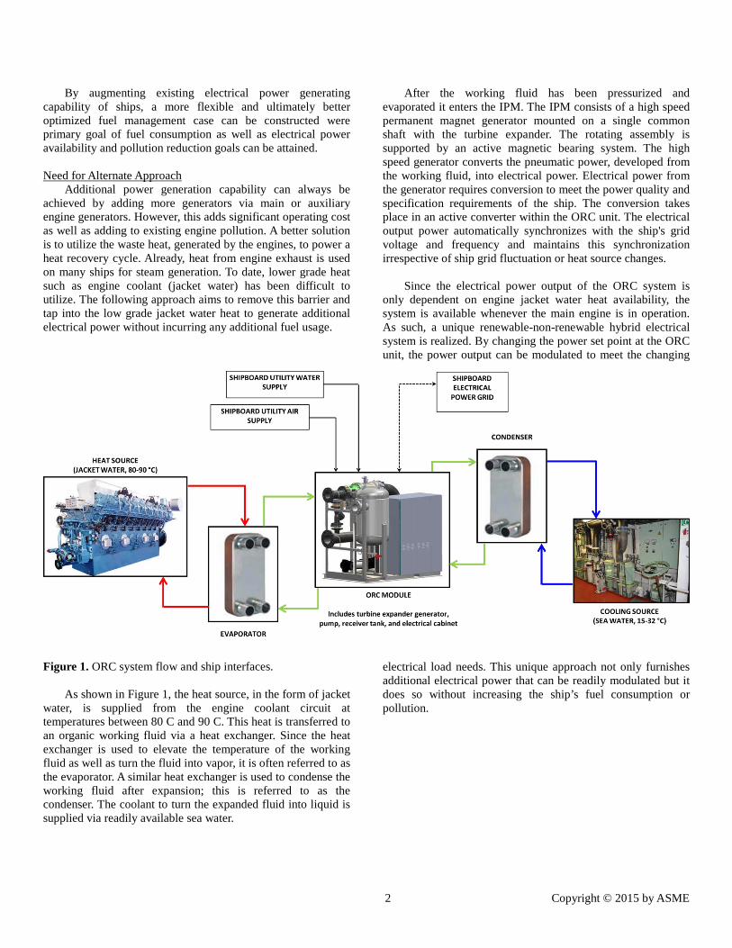
Figure 1. ORC system flow and ship interfaces.
As shown in Figure 1, the heat source, in the form of jacket water, is supplied from the engine coolant circuit at temperatures between 80 C and 90 C. This heat is transferred to an organic working fluid via a heat exchanger. Since the heat exchanger is used to elevate the temperature of the working fluid as well as turn the fluid into vapor, it is often referred to as the evaporator. A similar heat exchanger is used to condense the working fluid after expansion; this is referred to as the condenser. The coolant to turn the expanded fluid into liquid is supplied via readily available sea water.
After the working fluid has been pressurized and evaporated it enters the IPM. The IPM consists of a high speed permanent magnet generator mounted on a single common shaft with the turbine expander. The rotating assembly is supported by an active magnetic bearing system. The high speed generator converts the pneumatic power, developed from the working fluid, into electrical power. Electrical power from the generator requires conversion to meet the power quality and specification requirements of the ship. The conversion takes place in an active converter within the ORC unit. The electrical output power automatically synchronizes with the ship's grid voltage and frequency and maintains this synchronization irrespective of ship grid fluctuation or heat source changes.
Since the electrical power output of the ORC system is
only dependent on engine jacket water heat availability, the system is available whenever the main engine is in operation. As such, a unique renewable-non-renewable hybrid electrical system is realized. By changing the power set point at the ORC unit, the power output can be modulated to meet the changing
electrical load needs. This unique approach not only furnishes additional electrical power that can be readily modulated but it does so without increasing the ship’s fuel consumption or pollution.
3 Copyright © 2015 by ASME
MARINE ORC The Marine ORC system as a whole utilizes the ship's main
engine jacket water and sea water to facilitate evaporation and condensation of the organic working fluid to produce electric power. The low boiling point of the organic working fluid is fundamentally important to operating a Rankine cycle at a temperature below the boiling point of water.
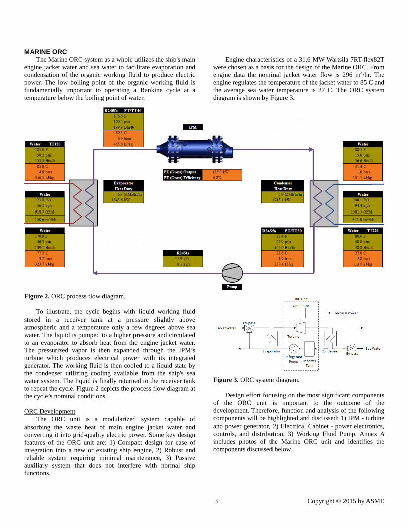
Figure 2. ORC process flow diagram.
To illustrate, the cycle begins with liquid working fluid stored in a receiver tank at a pressure slightly above atmospheric and a temperature only a few degrees above sea water. The liquid is pumped to a higher pressure and circulated to an evaporator to absorb heat from the engine jacket water. The pressurized vapor is then expanded through the IPM’s turbine which produces electrical power with its integrated generator. The working fluid is then cooled to a liquid state by the condenser utilizing cooling available from the ship's sea water system. The liquid is finally returned to the receiver tank to repeat the cycle. Figure 2 depicts the process flow diagram at the cycle’s nominal conditions.
ORC Development
The ORC unit is a modularized system capable of absorbing the waste heat of main engine jacket water and converting it into grid-quality electric power. Some key design features of the ORC unit are: 1) Compact design for ease of integration into a new or existing ship engine, 2) Robust and reliable system requiring minimal maintenance, 3) Passive auxiliary system that does not interfere with normal ship functions.
Engine characteristics of a 31.6 MW Wartsila 7RT-flex82T
were chosen as a basis for the design of the Marine ORC. From engine data the nominal jacket water flow is 296 m3/hr. The engine regulates the temperature of the jacket water to 85 C and the average sea water temperature is 27 C. The ORC system diagram is shown by Figure 3.
Figure 3. ORC system diagram.
Design effort focusing on the most significant components
of the ORC unit is important to the outcome of the development. Therefore, function and analysis of the following components will be highlighted and discussed: 1) IPM - turbine and power generator, 2) Electrical Cabinet - power electronics, controls, and distribution, 3) Working Fluid Pump. Annex A includes photos of the Marine ORC unit and identifies the components discussed below.
4 Copyright © 2015 by ASME
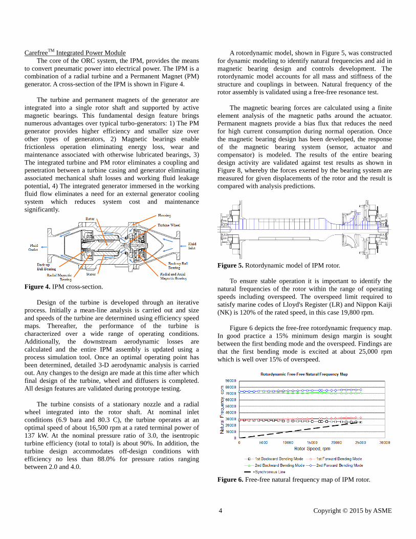
CarefreeTM Integrated Power Module The core of the ORC system, the IPM, provides the means
to convert pneumatic power into electrical power. The IPM is a combination of a radial turbine and a Permanent Magnet (PM) generator. A cross-section of the IPM is shown in Figure 4.
The turbine and permanent magnets of the generator are
integrated into a single rotor shaft and supported by active magnetic bearings. This fundamental design feature brings numerous advantages over typical turbo-generators: 1) The PM generator provides higher efficiency and smaller size over other types of generators, 2) Magnetic bearings enable frictionless operation eliminating energy loss, wear and maintenance associated with otherwise lubricated bearings, 3) The integrated turbine and PM rotor eliminates a coupling and penetration between a turbine casing and generator eliminating associated mechanical shaft losses and working fluid leakage potential, 4) The integrated generator immersed in the working fluid flow eliminates a need for an external generator cooling system which reduces system cost and maintenance significantly.
Figure 4. IPM cross-section.
Design of the turbine is developed through an iterative process. Initially a mean-line analysis is carried out and size and speeds of the turbine are determined using efficiency speed maps. Thereafter, the performance of the turbine is characterized over a wide range of operating conditions. Additionally, the downstream aerodynamic losses are calculated and the entire IPM assembly is updated using a process simulation tool. Once an optimal operating point has been determined, detailed 3-D aerodynamic analysis is carried out. Any changes to the design are made at this time after which final design of the turbine, wheel and diffusers is completed. All design features are validated during prototype testing.
The turbine consists of a stationary nozzle and a radial
wheel integrated into the rotor shaft. At nominal inlet conditions (6.9 bara and 80.3 C), the turbine operates at an optimal speed of about 16,500 rpm at a rated terminal power of 137 kW. At the nominal pressure ratio of 3.0, the isentropic turbine efficiency (total to total) is about 90%. In addition, the turbine design accommodates off-design conditions with efficiency no less than 88.0% for pressure ratios ranging between 2.0 and 4.0.
A rotordynamic model, shown in Figure 5, was constructed for dynamic modeling to identify natural frequencies and aid in magnetic bearing design and controls development. The rotordynamic model accounts for all mass and stiffness of the structure and couplings in between. Natural frequency of the rotor assembly is validated using a free-free resonance test.
The magnetic bearing forces are calculated using a finite
element analysis of the magnetic paths around the actuator. Permanent magnets provide a bias flux that reduces the need for high current consumption during normal operation. Once the magnetic bearing design has been developed, the response of the magnetic bearing system (sensor, actuator and compensator) is modeled. The results of the entire bearing design activity are validated against test results as shown in Figure 8, whereby the forces exerted by the bearing system are measured for given displacements of the rotor and the result is compared with analysis predictions.
Figure 5. Rotordynamic model of IPM rotor.
To ensure stable operation it is important to identify the natural frequencies of the rotor within the range of operating speeds including overspeed. The overspeed limit required to satisfy marine codes of Lloyd's Register (LR) and Nippon Kaiji (NK) is 120% of the rated speed, in this case 19,800 rpm.
Figure 6 depicts the free-free rotordynamic frequency map.
In good practice a 15% minimum design margin is sought between the first bending mode and the overspeed. Findings are that the first bending mode is excited at about 25,000 rpm which is well over 15% of overspeed.
Figure 6. Free-free natural frequency map of IPM rotor.

5 Copyright © 2015 by ASME
The rotor is supported by five active magnetic bearings.
The magnetic bearing design provides sufficient load capacity and load margin to ensure stable and robust operation under a variety of load sets. Sources of loading include the shaft weight, shaft unbalance, static offset (due to manufacturing variation), aerodynamic thrust, and external vibration. Electrical Cabinet
The ORC unit is fitted with a multi-functional electrical cabinet with three primary sections: 1) Power Electronics, 2) Programmable Logic and Magnetic Bearing Controls, 3) Power Distribution.
The Power Electronics (PE) is a fully digitized motor
controller with an active rectifier front end. It takes the variable, high-frequency power from the IPM generator and converts it to a regulated power that is synchronized to the ship’s grid. Using Insulated Gate Bipolar Transistors (IGBT), the power of the IPM generator is converted from AC to DC. DC is then converted back to AC to match the grid voltage and frequency. The digital controls of the PE control the speed of the IPM as well as monitor the temperatures of the IGBTs and inductors. Speed and temperature limits are programmed within the firmware. Requiring minimal cooling water (less than 30 L/min), the PE delivers up to 125 kW of grid quality power at 440 VAC / 60 Hz or 380 VAC / 50 Hz with a conversion efficiency greater than 93% and a power factor 0.99 or greater. Total harmonic distortion (THD) of output power to the grid is no greater than 5% at 125 kW.
The Programmable Logic Controller (PLC) allows the ORC unit to operate autonomously. It monitors the temperatures and pressures necessary for proper operation as well as controls the automated engine jacket water and sea water source valves. Using temperature monitoring and the source valves the PLC ensures ship functions are unaffected when the ORC is offline. During operation, it also actively prevents the ORC from cooling the engine jacket water below 75 C or heating the sea water above 32 C in order to safeguard the operation of the ship's fresh water maker.
The Magnetic Bearing Controller (MBC) provides 5-axis
control of the IPM’s active magnetic bearings. The MBC continuously monitors the rotor orbits and currents. Under adverse conditions such as high levels of unbalance or vibration the MBC sends a message to the PLC and the ORC system is shutdown in a controlled and safe manner.
The Power Distribution Unit (PDU) is the point of
interface to the ship’s electrical power supply. This section contains the necessary circuit breakers, contactors, filters and fuses to distribute power to the ship’s grid and ancillary ORC components.
Working Fluid Pump The working fluid pump is of centrifugal multistage design
and is mounted horizontally to aid in achieving compactness of the skid. A special feature of the pump is its low suction head which accommodates particularly cold condensing conditions encountered in colder oceans. The pump's motor is 3-phase, 2-pole and is rated for 7.5 kW. Driven by a variable frequency drive, the pump is capable of varying the cycle flow and pressure to compensate for varying heat source conditions and desired power generation settings. Reliability and Maintainability
The ORC comprises a number of Commercial Off-The-Shelf components (COTS), particularly in the electrical cabinet and power converter. The reliability of such components is governed by industry standards.
Since the IPM's generator uses the expanded working fluid
as coolant and the magnetic bearing system does not require any additional cooling, the entire IPM assembly is hermetically sealed. There are no rotating seals that require periodic maintenance. A hermetically sealed module together with non-wearing seals or bearings provides an inherently reliable, long lasting power module.
ORC TESTING Testing and validation of the ORC unit is primarily done in
two phases - factory testing and sea trials. The following discussion addresses factory testing, sea trails are a subset of such tests conducted at sea for further validation of the design in actual operating environment.
Several aspects of the ORC system are tested as individual
components before the system assembly is completed. Further testing is done at the system level to ensure conformance to system level requirements. The IPM is comprised of the high speed turbine expander together with the high speed PM generator. The rotating assembly is supported on an active magnetic bearing system. Due to the complexity of this module and significance in determining the overall ORC system performance, a number of component level tests are conducted and validated against requirements.
Figure 7. IPM under magnetic bearing load testing.
Vertical Force Applied to Rotor
6 Copyright © 2015 by ASME
The turbine expander magnetic bearing system is tested by
levitating and spinning the IPM rotor independent of the overall ORC system. Using the MBC, the performance of the bearing system can be monitored and recorded. Furthermore, any changes to the compensator can be made at this time. Load capacity of the magnetic bearings is validated using a load cell, see Figure 7. The plot in Figure 8 shows the measured axial force aside the theoretical axial force of the magnetic bearing.
Figure 8. Axial force vs. current – measured vs. theory.
The PE is also tested independent of the ORC system whereby the active rectifier and inverter are tested to maximum load capacity and temperatures at the heat sink are monitored and recorded. Once these subassemblies have been tested and validated, the ORC system assembly takes place.
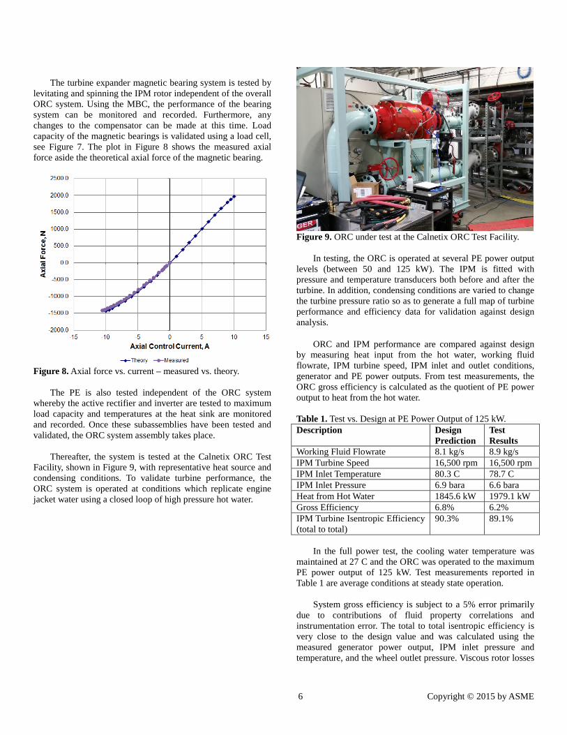
Thereafter, the system is tested at the Calnetix ORC Test
Facility, shown in Figure 9, with representative heat source and condensing conditions. To validate turbine performance, the ORC system is operated at conditions which replicate engine jacket water using a closed loop of high pressure hot water.
Figure 9. ORC under test at the Calnetix ORC Test Facility.
In testing, the ORC is operated at several PE power output
levels (between 50 and 125 kW). The IPM is fitted with pressure and temperature transducers both before and after the turbine. In addition, condensing conditions are varied to change the turbine pressure ratio so as to generate a full map of turbine performance and efficiency data for validation against design analysis.
ORC and IPM performance are compared against design by measuring heat input from the hot water, working fluid flowrate, IPM turbine speed, IPM inlet and outlet conditions, generator and PE power outputs. From test measurements, the ORC gross efficiency is calculated as the quotient of PE power output to heat from the hot water.
Table 1. Test vs. Design at PE Power Output of 125 kW. Description Design
Prediction Test Results
Working Fluid Flowrate 8.1 kg/s 8.9 kg/s IPM Turbine Speed 16,500 rpm 16,500 rpm IPM Inlet Temperature 80.3 C 78.7 C IPM Inlet Pressure 6.9 bara 6.6 bara Heat from Hot Water 1845.6 kW 1979.1 kW Gross Efficiency 6.8% 6.2% IPM Turbine Isentropic Efficiency (total to total)
90.3% 89.1%
In the full power test, the cooling water temperature was
maintained at 27 C and the ORC was operated to the maximum PE power output of 125 kW. Test measurements reported in Table 1 are average conditions at steady state operation.
System gross efficiency is subject to a 5% error primarily
due to contributions of fluid property correlations and instrumentation error. The total to total isentropic efficiency is very close to the design value and was calculated using the measured generator power output, IPM inlet pressure and temperature, and the wheel outlet pressure. Viscous rotor losses
7 Copyright © 2015 by ASME
and generator efficiency correlations were necessary to arrive at the isentropic efficiency given the inability to measure these quantities directly.
CONCLUSIONS In this paper a need to develop a heat recovery system
utilizing low grade heat from ship engine jacket water has been outlined. Such a need arises to address the ever increasing electrical power demands of modern ships whilst reducing overall pollution emanating from power generating sources.
To achieve this goal, development of a novel low grade
heat source ORC system had been outlined. Such a system not only achieves the primary goal of electric power generation without additional fuel consumption, it also adds to overall electrical power availability and adds a dimension to overall electrical system flexibility. The latter is the cornerstone of the renewable-non-renewable hybrid architecture.
Performance test results have been provided and analyses
of key performance metrics have been discussed. Much of the discussion in this paper has been focused at marine application
of such architecture. It should be noted, with the abundance of low grade heat sources, such as low-temperature geothermal, the same architecture, using the same ORC system, can be achieved in many other low grade heat recovery applications.
REFERENCES [1] Hawkins, L., Zhu, L., Blumber, E., Mirmobin, P., and
Erdlac Jr., R., Oct. 2012, “Heat-To-Electricity with High-Speed Magnetic Bearing/Generator System”, 2012 GRC Annual Meeting.
[2] Hawkins, L., Zhu, L., and Blumber, E., Jul. 2011,
"Development of a 125 kW AMB Expander/Generator for Waste Heat Recovery," Journal of Engineering for Gas Turbines and Power, Vol. 133.
[3] McMullen, P., Huynh, C., and Hayes, R., 2000,
"Combination Radial-Axial Magnetic Bearing," Proceedings of the Seventh International Symposium on Magnetic Bearings, Zurich, Switzerland.

8 Copyright © 2015 by ASME
ANNEX A
PHOTOS OF THE MARINE ORC
Power Distribution Unit Power Electronics Programmable Logic and Magnetic Bearing Controller
Integrated Power Module
Working Fluid Pump
Interface Piping to Evaporator and Condenser
Receiver Tank