Embed Size (px)
Citation preview
PROCEEDINGS OF ASME 2011 5TH INTERNATIONAL CONFERENCE ON ENERGY SUSTAINABILITY & 9TH FUEL CELL SCIENCE, ENGINEERING AND TECHNOLOGY CONFERENCE
ESFUELCELL2011 AUGUST 7-10, 2011, WASHINGTON, DC, USA
ESFUELCELL2011-54369
MAXIMIZING THE USE OF PLATINUM CATALYST BY ULTRASONIC SPRAY APPLICATION
Robb Engle Technical Services Director, Sono-Tek Corporation
Milton, NY, USA
ABSTRACT The following discusses the method and advantages of
ultrasonic deposition of carbon-based platinum ink solution onto catalytic membranes in the manufacture of platinum-based fuel cells, doubling industry standard performances.
Using patented ultrasonic atomization technology[1], conductive properties are compared to those of films created with hydraulic deposition and paste printing methods, using comprehensive analysis of morphology characteristics, deposition density, and distribution of platinum particles throughout the thickness and surface area of the coating.
Results indicate significant increase in uniform distribution of platinum particles using the ultrasonic deposition method. Measured electrochemically active Pt surface area using ultrasonic atomization was recorded as high as 71% of the total Pt particle surface area.
BACKGROUND
Basic Theory
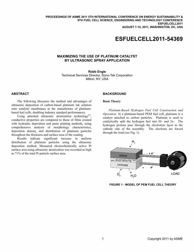
Platinum-Based Hydrogen Fuel Cell Construction and
Operation: In a platinum-based PEM fuel cell, platinum is a catalyst attached to carbon particles. Platinum is used to catalytically split the hydrogen fuel into H+ and 2e-. The hydrogen protons pass through the electrolyte layer to the cathode side of the assembly. The electrons are forced through the load (see Fig. 1).
FIGURE 1 - MODEL OF PEM FUEL CELL THEORY
1 Copyright 2011 by ASME

The Process Objectives of Platinum Black-Based Hydrogen Fuel Cell Construction and Operation
1. Maximum Surface Area Exposure of Platinum to Gas Flow
Platinum is an oxidizer in the reaction and its efficacy is related directly to the surface area of platinum being exposed to the gas. If the platinum were in large particles, much of its benefit would be lost as its mass inside is not exposed to the gas; therefore, particles of very small sizes are used. A common method to characterize this is to examine the Sauter Mean Diameter. Equation (1)[2] is frequently used in combustion related applications as those reactions also relate the surface area to total potential in correspondence to the efficiency of the burn:
d32≡∑inidi3/∑inidi
2 (1) (1)
In order to have the most efficient use of the costly platinum (see Fig. 2), it must be of the smallest size the cost will allow and it must be uniformly dispersed in a “web” of carbon. None of the many methods of obtaining this web, such as pressing, knife edge or printing of the “paste” of carbon and platinum ensure satisfactory dispersion. In fact, the platinum can quite easily be clumped in agglomerations. Creating the catalyst layer in a manner that ensures dispersion and uniform exposure of the platinum walls is paramount.
FIGURE 2 - PLATINUM PRICING 5 YEAR
(USD PER TROYOZ)[3]
2. Maximum Uniformity of Film Thickness
The process of creating the web of platinum and carbon should ensure that the thickness of the coating is uniformly maintained, as the thickness of a properly dispersed platinum quantity maximizes the amount of platinum available to the flow of gas. In locations of low thickness relative to the mean, lower electron separation will occur and cells will be less efficient in this area. Often, to counter such occurrences, the platinum loading will be increased such that the minimum thickness will ensure 100% chemical conversion. But this results in wasted platinum at all the mean and heavier than mean thicknesses. Conversely, high relative availability may result in hot spots, the enemy of PEM-Hydrogen fuel cells.
Paste printing processes have often been measured at 25 microns thick +/- 6 microns, which means these thicknesses may vary by as much as 53%. It is most desirable to have a uniformly thick layer of the catalyst such that all surfaces of the electrolyte can be used (see fig. 3).
FIGURE 3 - EXAMPLES OF KNIFE COATING UNIFORMITY COMPARED WITH ULTRASONIC SPRAY
(THEORETICAL MODEL)[4]
2 Copyright 2011 by ASME
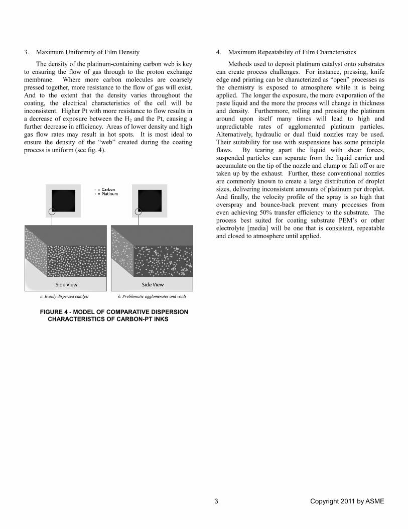
3. Maximum Uniformity of Film Density
The density of the platinum-containing carbon web is key to ensuring the flow of gas through to the proton exchange membrane. Where more carbon molecules are coarsely pressed together, more resistance to the flow of gas will exist. And to the extent that the density varies throughout the coating, the electrical characteristics of the cell will be inconsistent. Higher Pt with more resistance to flow results in a decrease of exposure between the H2 and the Pt, causing a further decrease in efficiency. Areas of lower density and high gas flow rates may result in hot spots. It is most ideal to ensure the density of the “web” created during the coating process is uniform (see fig. 4).
FIGURE 4 - MODEL OF COMPARATIVE DISPERSION CHARACTERISTICS OF CARBON-PT INKS
4. Maximum Repeatability of Film Characteristics
Methods used to deposit platinum catalyst onto substrates can create process challenges. For instance, pressing, knife edge and printing can be characterized as “open” processes as the chemistry is exposed to atmosphere while it is being applied. The longer the exposure, the more evaporation of the paste liquid and the more the process will change in thickness and density. Furthermore, rolling and pressing the platinum around upon itself many times will lead to high and unpredictable rates of agglomerated platinum particles. Alternatively, hydraulic or dual fluid nozzles may be used. Their suitability for use with suspensions has some principle flaws. By tearing apart the liquid with shear forces, suspended particles can separate from the liquid carrier and accumulate on the tip of the nozzle and clump or fall off or are taken up by the exhaust. Further, these conventional nozzles are commonly known to create a large distribution of droplet sizes, delivering inconsistent amounts of platinum per droplet. And finally, the velocity profile of the spray is so high that overspray and bounce-back prevent many processes from even achieving 50% transfer efficiency to the substrate. The process best suited for coating substrate PEM’s or other electrolyte [media] will be one that is consistent, repeatable and closed to atmosphere until applied.
3 Copyright 2011 by ASME
TECHNOLOGY OVERVIEW
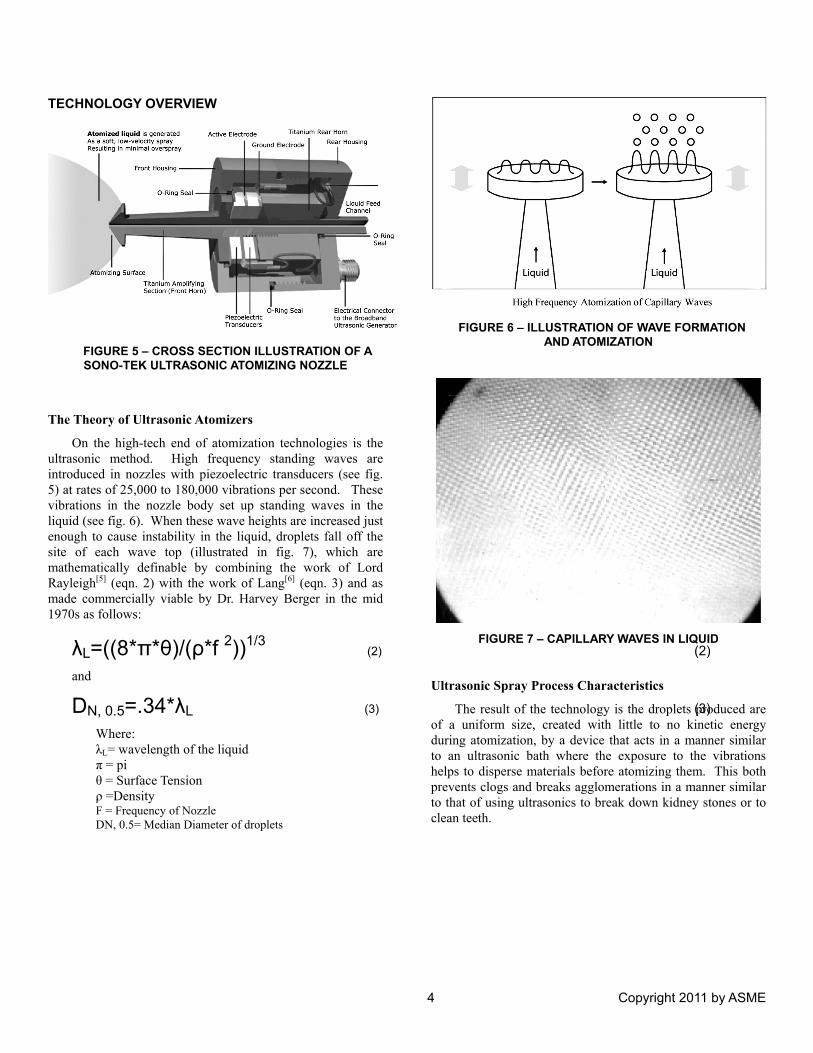
FIGURE 5 – CROSS SECTION ILLUSTRATION OF A SONO-TEK ULTRASONIC ATOMIZING NOZZLE
The Theory of Ultrasonic Atomizers
On the high-tech end of atomization technologies is the ultrasonic method. High frequency standing waves are introduced in nozzles with piezoelectric transducers (see fig. 5) at rates of 25,000 to 180,000 vibrations per second. These vibrations in the nozzle body set up standing waves in the liquid (see fig. 6). When these wave heights are increased just enough to cause instability in the liquid, droplets fall off the site of each wave top (illustrated in fig. 7), which are mathematically definable by combining the work of Lord Rayleigh[5] (eqn. 2) with the work of Lang[6] (eqn. 3) and as made commercially viable by Dr. Harvey Berger in the mid 1970s as follows:
λL=((8*π*θ)/(ρ*f 2))1/3 (2)
(2)
and
DN, 0.5=.34*λL (3) (3)
Where: λL= wavelength of the liquid π = pi θ = Surface Tension ρ =Density F = Frequency of Nozzle DN, 0.5= Median Diameter of droplets
FIGURE 6 – ILLUSTRATION OF WAVE FORMATION
AND ATOMIZATION
FIGURE 7 – CAPILLARY WAVES IN LIQUID
Ultrasonic Spray Process Characteristics
The result of the technology is the droplets produced are of a uniform size, created with little to no kinetic energy during atomization, by a device that acts in a manner similar to an ultrasonic bath where the exposure to the vibrations helps to disperse materials before atomizing them. This both prevents clogs and breaks agglomerations in a manner similar to that of using ultrasonics to break down kidney stones or to clean teeth.
4 Copyright 2011 by ASME
Technology Advantages of Ultrasonic Atomizers : Ultrasonic nozzles produce a soft, low velocity spray resulting in a minimum of overspray. When low velocity gas is used to shape the spray plumes of ultrasonic atomizers, the highest transfer efficiencies of expensive materials are possible. Specifically, the following are inherent conditions:
1. The technology allows for a large turn down ratio of
flow rates, maximizing the flexibility of an atomizing platform.
2. The large orifice and ultrasonics make it possible to atomize high-solid materials without any concern for clogging.
3. The nozzle’s titanium construction makes it highly inert to many solvents resulting in high reliability and long life.
THE PROCESS
The Application of Ultrasonic Atomizers to Catalyst Dispersions
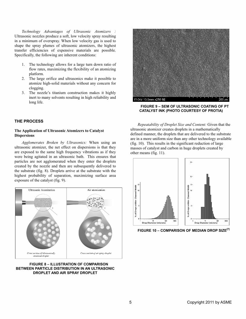
Agglomerates Broken by Ultrasonics: When using an ultrasonic atomizer, the net effect on dispersions is that they are exposed to the same high frequency vibrations as if they were being agitated in an ultrasonic bath. This ensures that particles are not agglomerated when they enter the droplets created by the nozzle and then are subsequently delivered to the substrate (fig. 8). Droplets arrive at the substrate with the highest probability of separation, maximizing surface area exposure of the catalyst (fig. 9).
FIGURE 8 – ILLUSTRATION OF COMPARISON
BETWEEN PARTICLE DISTRIBUTION IN AN ULTRASONIC DROPLET AND AIR SPRAY DROPLET
FIGURE 9 – SEM OF ULTRASONIC COATING OF PT
CATALYST INK (PHOTO COURTESY OF PROTIA) Repeatability of Droplet Size and Content: Given that the
ultrasonic atomizer creates droplets in a mathematically defined manner, the droplets that are delivered to the substrate are in a more uniform size than any other technology available (fig. 10). This results in the significant reduction of large masses of catalyst and carbon in huge droplets created by other means (fig. 11).
FIGURE 10 – COMPARISON OF MEDIAN DROP SIZE[7]
5 Copyright 2011 by ASME
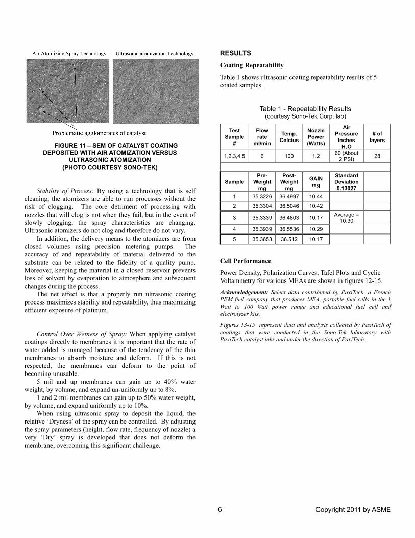
FIGURE 11 – SEM OF CATALYST COATING
DEPOSITED WITH AIR ATOMIZATION VERSUS ULTRASONIC ATOMIZATION
(PHOTO COURTESY SONO-TEK) Stability of Process: By using a technology that is self
cleaning, the atomizers are able to run processes without the risk of clogging. The core detriment of processing with nozzles that will clog is not when they fail, but in the event of slowly clogging, the spray characteristics are changing. Ultrasonic atomizers do not clog and therefore do not vary.
In addition, the delivery means to the atomizers are from closed volumes using precision metering pumps. The accuracy of and repeatability of material delivered to the substrate can be related to the fidelity of a quality pump. Moreover, keeping the material in a closed reservoir prevents loss of solvent by evaporation to atmosphere and subsequent changes during the process.
The net effect is that a properly run ultrasonic coating process maximizes stability and repeatability, thus maximizing efficient exposure of platinum.
Control Over Wetness of Spray: When applying catalyst
coatings directly to membranes it is important that the rate of water added is managed because of the tendency of the thin membranes to absorb moisture and deform. If this is not respected, the membranes can deform to the point of becoming unusable.
5 mil and up membranes can gain up to 40% water weight, by volume, and expand un-uniformly up to 8%.
1 and 2 mil membranes can gain up to 50% water weight, by volume, and expand uniformly up to 10%.
When using ultrasonic spray to deposit the liquid, the relative ‘Dryness’ of the spray can be controlled. By adjusting the spray parameters (height, flow rate, frequency of nozzle) a very ‘Dry’ spray is developed that does not deform the membrane, overcoming this significant challenge.
RESULTS
Coating Repeatability
Table 1 shows ultrasonic coating repeatability results of 5 coated samples.
Table 1 - Repeatability Results (courtesy Sono-Tek Corp. lab)
Test Sample
#
Flow rate
ml/min
Temp. Celcius
Nozzle Power (Watts)
Air Pressure Inches
H2O
# of layers
1,2,3,4,5 6 100 1.2 60 (About 2 PSI) 28
Sample Pre-
Weightmg
Post-Weight
mg
GAIN mg
Standard Deviation 0.13027
1 35.3226 36.4997 10.44
2 35.3304 36.5046 10.42
3 35.3339 36.4803 10.17 Average = 10.30
4 35.3939 36.5536 10.29
5 35.3653 36.512 10.17
Cell Performance
Power Density, Polarization Curves, Tafel Plots and Cyclic Voltammetry for various MEAs are shown in figures 12-15.
Acknowledgement: Select data contributed by PaxiTech, a French PEM fuel company that produces MEA, portable fuel cells in the 1 Watt to 100 Watt power range and educational fuel cell and electrolyzer kits.
Figures 13-15 represent data and analysis collected by PaxiTech of coatings that were conducted in the Sono-Tek laboratory with PaxiTech catalyst inks and under the direction of PaxiTech.
6 Copyright 2011 by ASME
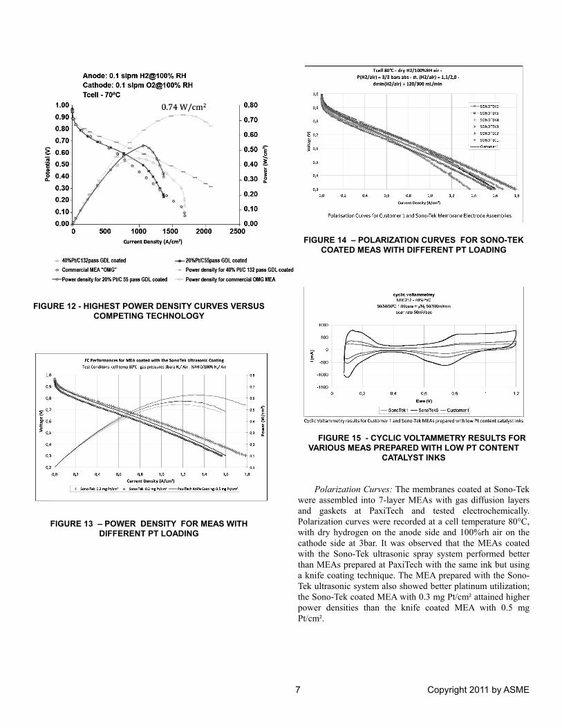
FIGURE 12 - HIGHEST POWER DENSITY CURVES VERSUS COMPETING TECHNOLOGY
FIGURE 13 – POWER DENSITY FOR MEAS WITH DIFFERENT PT LOADING
FIGURE 14 – POLARIZATION CURVES FOR SONO-TEK COATED MEAS WITH DIFFERENT PT LOADING
FIGURE 15 - CYCLIC VOLTAMMETRY RESULTS FOR
VARIOUS MEAS PREPARED WITH LOW PT CONTENT CATALYST INKS
Polarization Curves: The membranes coated at Sono-Tek
were assembled into 7-layer MEAs with gas diffusion layers and gaskets at PaxiTech and tested electrochemically. Polarization curves were recorded at a cell temperature 80°C, with dry hydrogen on the anode side and 100%rh air on the cathode side at 3bar. It was observed that the MEAs coated with the Sono-Tek ultrasonic spray system performed better than MEAs prepared at PaxiTech with the same ink but using a knife coating technique. The MEA prepared with the Sono-Tek ultrasonic system also showed better platinum utilization; the Sono-Tek coated MEA with 0.3 mg Pt/cm² attained higher power densities than the knife coated MEA with 0.5 mg Pt/cm².
7 Copyright 2011 by ASME
8 Copyright 2011 by ASME
Cyclic Voltammetry: The potential of the working electrode was scanned linearly from 0.08V to 1.2V where the direction of the scan was reversed. The current response as a result of this polarization was then plotted as a function of the applied potential. The cyclic voltammogram gives information about the reactions occurring on the working electrode surface. The peak due to the adsorption/desorption of the hydrogen layer can be analyzed to give information concerning the total surface area of the platinum catalyst available for the electrochemical reactions.
The percentage of the electrochemically measured Pt surface area compared to the total Pt particle surface area (calculated using the catalyst loading and particle size data) was in the range of 62% for the Sono-Tek 0.2mg/cm² MEA and 71% for the Sono-Tek 0.5mg/cm² MEA. These values are extremely high and show that a very large percentage of the platinum catalyst surface is electrochemically active.
Conclusion
The use of ultrasonic atomization equipment has been demonstrated to produce a significant increase in the uniformity, distribution and repeatability of the expensive platinum catalyst used in the manufacturing of PEM fuel cells. These advantages combine to increase the power output of the cell relative to the platinum loading or reduce the amount of platinum consumed in the process or both, as the process engineer requires.
ACKNOWLEDGMENTS Select data contributed by PaxiTech, France 32 rue de
Comboire, Bâtimentt B1, 38130 Echirolles, France 33-(0)4 76 09 14 48 Paxitech is a PEM fuel company that produces MEA, portable fuel cells in the 1 Watt to 100 Watt power range and educational fuel cell and electrolyzer kits.
Figures 13, 14, and 15 represent data and analysis collected by PaxiTech of coatings that were conducted in the Sono-Tek laboratory with PaxiTech catalyst inks and under the direction of PaxiTech.
Coatings were conducted in Sono-Tek lab under the direction of PaxiTech. Analysis and data collection of coating results was conducted at PaxiTech.
The following equipment was provided by Sono-Tek
Corporation to conduct testing: AccuMist ultrasonic nozzle Impact ultrasonic nozzle SonicSyringe ultrasonic dispersion syringe pump ExactaCoat XYZ coating system FlexiCoat XYZ coating system
REFERENCES
[1] Ultrasonic atomization technology provided by Sono-Tek [2] Berger, H., 1998, Ultrasonic Liquid Atomization, pp.2 [3] Figure 2 - Chart from
http://www.platinum.matthey.com/pgm-prices/price-charts/
[4] Figure 3a -
http://getcheminfo.wikispaces.com/file/view/LipidBilayer1.jpg/95877804/LipidBilayer1.jpg
[5] Rayleigh, 1898, “Theory of Sound” [6] Lang, 1962, “Journal of the Acoustic Society of
America” vol. 34,6 [7] Berger, H., 1998, Sono-Tek Corporation


![Ultrasonic flowmeter for use with transmitter type FUS060 · for use with transmitter type FUS060 [] ... SITRANS F US ultrasonic flowmeter sensor type SONO 3300 2-track with transmitter](https://img.pdfslide.net/doc/110x75/5ae2ce877f8b9ae74a8cec2e/ultrasonic-flowmeter-for-use-with-transmitter-type-use-with-transmitter-type-fus060.jpg)