Embed Size (px)
Citation preview

INFORMATION CIRCULAR/1992
Proceedings of the Workshop on Coal Pillar Mechanics and Design
Compiled by Anthony T. lannacchione, Christopher Mark, Richard C. Repsher, Robert J. Tuchman, and Caddie C. Jones
United States Department of the Interior
Bureau of Mines

158
A METHOD REVISITED: COAL PILLAR STRENGTH FORMULA BASED ON FIELD INVESTIGATIONS
By Z. T. Bieniawski1
INTRODUCTION
The design of mine pillars involves the determination of proper sizes of pillars compatible with the expected load and the in situ strength of the coal strata. Thus, in deciding the most suitable dimensions for mine pillars, one needs to consider such factors as the pillar load (the stress on pillars), the pillar strength, and the factors of safety.
There are two approaches to coal pillar design. The ultimate strength approach contends that pillars will fail when the applied load reaches the compressive strength of the pillars. This approach presumes that the loadbearing capacity of a pillar reduces to zero the moment its ultimate strength is exceeded. The progressive failure approach emphasizes the nonuniform stress distribution in the pillar; failure initiates at the most crucial point and propagates gradually to ultimate failure. In the United States, the Federal Coal Mine Health and Safety Act of 1%9 prescribes the safety concept of failure initiation as the criterion rather than ultimate failure. This results in an additional margin of safety. This paper summarizes a method developed by the author for determination of coal pillar strength that has been used successfully for more than 20 years. The recommended procedure is supported by a survey of approximately 200 coal mines, uicluding 174 in the United States, in which typical mining conditions and pillar configurations were analyzed.
PILLAR LOAD
The simplest approach to determine the pillar load, or
where Sp = pillar load (average pillar stress) in psi,
H depth below surface, ft,
B width of opening (room or entry), ft,
w pillar width, ft,
and L = pillar length, ft.
For longwall mining applications, where abutment loading is of prime importance, the Analysis of Longwall Pillar Stability (ALPS) method proposed by Mark and Bieniawski (1986) (11)2 can be used to estimate the pillar stresses for headgate and tailgate loading conditions.
PILLAR STRENGTH
The strength of coal pillars, i.e., the ultimate load per unit area, is dependent upon three elements: (1) the size or volume effect (strength reduction from a smalllaboratory specimen of coal to a full-size coal pillar), (2) the effect of pillar geometry (shape effect), and (3) the properties of the coal material. Although for years many pillar strength formulas have been proposed, some dating back to 1911, two types of expressions are predominant:
O"p = O"cube [A + B (w/h)], (2)
more correctly the average pillar stress, is by the tributary and area method. This approach is generally only applicable (3) to room-and-pillar mining and to sizing pillars for the de-velopment entries in longwall mining. If a number of well- where 0" P = pillar strength, known simplifying assumptions are made (e.g., uniform stress distributions, large extent of mining), the average pillar load for such cases can be calculated from
Sp = [1.1 H (w + B)(L + B)] / (w xL), (1)
lProfessor of Mineral Engineering, The Pennsylvania State University, University Park, PA.
0" cube = in situ coal strength incorporating size effect,
A, B, a, b = constants expressing the shape effect,
2ltalic numbers in parentheses refer to items in the list of references at the end of this paper.

159
K = constant characteristic of a coal seam, In the previous equations, the constant k must be deter-mined for each coal seam; k is obtained as shown by
w = pillar width, Gaddy (1956) (7): .
and h = pillar height (usually same as seam height).
SIZE EFFECT
The size effect is best characterized by the concept of the "critical size" (Bieniawski, 1968) (1), which is very important in practical strata control engineering. It means that for cubical specimens of coal (no shape effect involved), the strength decreases with increasing specimen size until the strength becomes nearly constant from a certain "critical specimen size" onward. This phenomenon is depicted in figure 1, and its significance is that the strength values at the critical size, about 3 ft (1.0 m) for coal, are directly applicable to full-size pillars.
The size effect characterizes the difference in the strength between the small-size specimens tested in the laboratory and the large-size coal pillars mined in situ. Research in the United States has shown [Hustrulid, 1976 (10)] that the scaling of coal properties from laboratorymeasured data to field values can be satisfactorily achieved by the following equations:
(4)
applicable to cubical pillars if the height h is more than 36 in (0.9 m), or
- k / hl/2 O'cube - (5)
applicable to cubical pillars if the height h is less than 36 in (0.9 m).
5,000 r---.-----.----r--.----.--~----,
'iii KEY Q. 0 Dota from Bureau of Mines £ 4,000 c Data from Gaddy .... I> Data from Greenwald t!)
<:J Data from Daniels and Moore Z ...JW 3,000 - - - O'c: 65940-1/2 (based on strength «0:: of 4" cubes) - ....
- O'c: 5;(,180-1/2(based on strength Xen « of 2 cubes) -W Z> 2,000 =>-en en
W 0:: 1,000 <:J ---a.. rf' ----~ ----
0 U (Sample disturbed)o
0 10 20 30 40 50 60 70
CUBE EDGE LENGTH, in
Figure 1.-Compresslve strength as a function of cube size for Pittsburgh coal (Hustrulld, 1976 (10)].
(6)
where 0' C = uniaxial compressive strength of coal specimens tested in laboratory, psi,
and D = diameter or cube side dimension, in.
While there is a difference in laboratory results depending on whether cylindrical or cubical specimens are used, for practical engineering purposes this difference is not significant within the range of D between 2 and 4 in (50 and 100 mm) [Hustrulid, 1976 (10)].
Although the strength of coal at the critical size is most conveniently determined by the Hustrulid equations, a number of other approaches can also be used. These are as follows: in situ large-scale tests, "petite sismique" geophysical tests, the Protodyakonov method, and the Hoek-Brown criterion for rock mass strength [Bieniawski, 1984 (5)].
SHAPE EFFECT
From all the available pillar strength formulas, the following five expressions are most commonly used in coal mining:
Obert-Duvall, 1967 (13):
O'p = O'cube (0.778 + 0.222 w/h)
Holland-Gaddy, 1964 (8):
O'p = k [w/hl/2]
Holland, 1973 (9):
Salamon-Munro, 1967 (14):
0' = 1 320 wo.46/ho.66 p ,
Bieniawski, 1968 (2-4):
Up = O'cube (0.64 + 0.36 w/h).
(7)
(8)
(9)
(10)
(11)

160
PILLAR STRENGTH FORMULA
The origin and the use of equation 11 are the prime topics of this paper. This pillar strength formula was proposed [Bieniawski, 1968 (2)] on the basis of extensive in situ tests performed on coal during 1966-73 in South Africa. The program of tests was initiated as a result of a coal mine disaster at Coalbrook Mine where 427 miners lost their lives in 1960 because of pillar collapse.
Conducted under the author's direction at Witbank Mine, the first series of tests (1966-68) involved 35 largescale in situ tests on square coal specimens measuring from 24 in to 6 ft (0.6 to 2 m) in side length and of various heights. The influence of the width-to-height ratios of up to 3.1 was studied by testing specimens of different heights and with the same cross-sectional area. The second series of tests involved 12 specimens tested by Wagner in 1972 at Usutu Mine (15). These tests included rectangular and square specimens up to 6 ft (2 m) in size and with width-to-height ratios of up to 2.2.
The third and last series of tests, also conducted under the author's direction, was performed in 1973 at New Largo Mine and involved 10 in situ coal specimens, 4.5 by 4.5 ft (1.4 by 1.4 m) in cross section and of various heights, with width-to-height ratios of up to 3.4. Full details of all the specimen preparation and testing techniques are given by Bieniawski and van Heerden (1975) (3).
The Witbank coal formation was the weakest of the three tested, while the New Largo coal was the strongest. To make the in situ test results generally applicable (i.e., not only to the locality where the tests were carried out), a pillar strength formula is best expressed in a normalized form. For example, the original strength formula for the Witbank Coalfield [Bieniawski, 1968 (2)] was of the form
Up (psi) = 400 + 220 w Ih,
but this can be expressed dimensionlessly as
Up = 620 (0.64 + 0.36 w/h),
where U cube = 620 psi (4.3 MPa) is the "critical size" strength for the Witbank coal.
Thus, the general (normalized) form of this pillar strength formula is
Up = ucube (0.64 + 0.36 w/h),
which is equation 11 given earlier. In figure 2, all the in situ test results from the three coal mines are plotted, demonstrating the close fit of the experimental data with equation 11.
In essence, this pillar strength formula-confirmed by 57 large-scale in situ tests on coal performed in three mines-is applicable to any coal seam, provided the value of U cube is known from equation 4 or by other means. The formula can be used not only in room-and-pillar mining but also in longwall mining, provided the appropriate stability factors are established, as discussed in the next section. Note that although the original in situ test data in figure 2 were based on pillar width-to-height ratios of up to 3.4, when applied to full size coal pillars-as shown later in figure 7-the pillar strength formula given by equation 11 was found applicable even for pillar widthto-height ratios of up to 12.
b c ., e c:; ., ~ II) ... 0
.s;;
0-c ~ Ui
.. 0 ~ ct 0::
b ~ 3r-----~------r_----.-----~r_----,
" .s;; "-
" == i c CD § u ., ~ Il) ... 0
== '" c ., ~
2
I
0
<TIU1 = 0.64 + 0.36 w/h
KEY o New Largo colliery C Usutu colliery x Witbank colliery
2 3
w/h ratio
4 5
Figure 2.-Strength data from larg.acale In aHu tea .. on coal [Blenlawakl and van Hearden, 1975 (11»).

161
CHOICE OF A STABILITY FACTOR
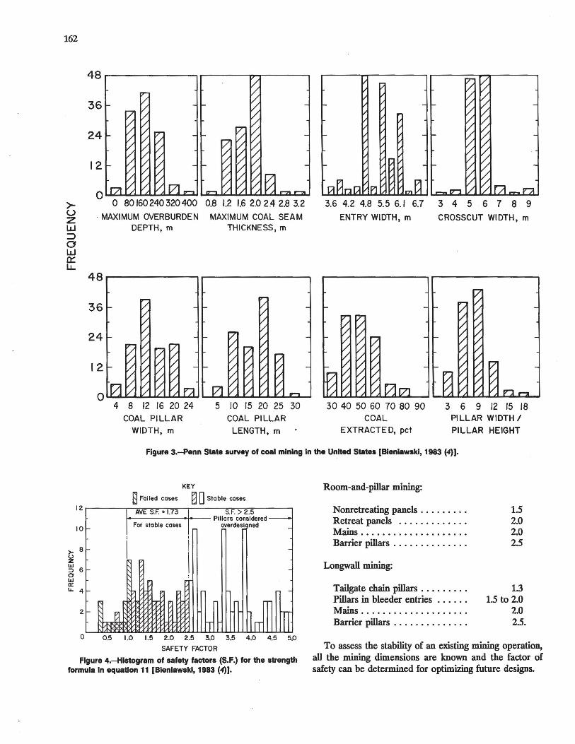
To use any pillar strength formula with confidence, the appropriate "safety factor" or "stability factor" must be used.3 For the Bieniawski formula (equation 11), this was accomplished in a 1982 national survey of design practices and mining dimensions in the United States [Bieniawski, 1983 (4)]. This survey included a comprehensive study of such parameters as the depth below surface, seam thickness, roof span, pillar height, pillar width, pillar length, width-to-height ratios, percentage extraction, and method of design. A total of 174 cases were available for stability analyses of coal pillars (see table 1) plus 58 cases of roof falls for analyzing roof spans. The pillar cases included only three instances of pillar failure from the United States. However, 20 pillar failure cases in other countries were also collected by the author. Nevertheless, pillar failure cases were not essential for establishing the validity of a selected pillar strength formula for U.S. mining, contrary to an objective of a study by Salamon and Munro (1967) (13) in South Africa. There, no pillar strength formula was available at the time, while in the United States a number of formulas have been used since 1911. It was the aim of the 1982 national survey to select a formula that would be the most economical yet safe for coal pillar design in the United States.
Table 1.-Range of room-and-plllar parameters surveyed In U.S. coal mlnest
Parameter
Depth below surface ft .. Seam or pillar height ..... ft .. Entry width ...... . ..... ft .. Pillar width .. . ......... , ft . . Pillar length ........... . ft .. Width-to-height ratio . . . . .. ft .. Length-to-width ratio .... . ft .. Extraction ..........•. pct ..
Rangel
75-1,500 3-15
16-20 15-75 20-90
2-16 1-3
25-85
Ipennsylvania State University survey of 174 cases. lTo convert feet to meters, multiply by 0.30.
Typical value2
500 6
18 48 60 8.0
1.25 50
The results obtained are depicted in figure 3. The survey involved the coal seams commonly found in the United States. However, 38 pct of the data involved the Pittsburgh Seam. The average depth of room-and-pillar mines in the United States is 500 ft (150 m), with the range varying between 75 and 1,500 ft (25 and 480 m). The typical seam thickness, which is synonymous with pillar height,
3 A better term would be "a factor of ignorance" because of the uncertainties inherent in any empirical approach.
is 6 ft (2 m) varying between 3 and 15 ft (1.0 and 4.5 m). Roof spans (i.e., entry widths) in the United States are typically 16 to 20 ft (4-6 m) wide. The typical pillar width is 48 ft (15 m) varying from 15 to 75 ft (5 to 23 m) while the typical pillar length is 60 ft (20 m). The average percentage extraction is 50 pct varying between 25 to 85 pct. An important observation from figure 3 is that the typical pillar width-to-height ratio is 8.0 varying from 2 to 16. Based on this survey, the appropriate safety factors for the Bieniawski formula (equation 11) were established.
A factor of safety F is defined as the ratio of the strength of a pillar to the load acting on it. Thus,
(12)
A factor of safety (stability factor) is necessary because in order to derive the pillar load as well as the strength formulas presented in the previous section, certain assumptions had to be made.
A structure is generally defined as stable when F is more than 1. In engineering practice, the factor of safety used is smaller when the conditions are well explored and understood. If the factor of safety is unity, the probability of failure is 50 pct. The factor of safety should be greater than unity to achieve a low probability of failure. What probability of failure is acceptable in coal mining?
Using a computer storage and retrieval system, the room-and-pillar dimensions from the Pennsylvania State survey were used together with the various pillar strength . formulas. A histogram of safety factors for the strength formula in equation 11 is given in figure 4 for 171 case histories featuring stable pillars from the United States, 20 case histories involving failed pillars in other countries, and 3 cases of failed pillars in the United States.
It is concluded from figure 4 that factors of safety ranging from 1.5 to 2.0 are appropriate for room-and-pillar coal mining when using equation 11. For longwall mining, using the ALPS method developed at The Pennsylvania State University by Mark and Bieniawski (1986) (11), the recommended factor of safety is 1.3. It must be emphasized, however, that these figures should be used as a guide only and the local mining experience should be taken into consideration.
More specifically, the guidelines for the stability factors using the Bieniawski formula are as follows:
162
>u z w :::::> o w a::: LL.
48 ~-------, .-------..------,
36
24
12
o 80 160240 320400 0.8 1.2 1.6 2,0 2.4 2.8 3.2 MAXIMUM OVERBURDEN MAXIMUM COAL SEAM
DEPTH, m THICKNESS, m
48..-------......, r--------.....,
4 8 12 /6 20 24 COAL PILLAR
WIDTH, m
5 /0 15 20 25 30 COAL PILLAR
LENGTH, m
3.6 4.2 4.8 5.5 6.1 6.7 3 4 5 6 7 8 9 ENTRY WIDTH, m CROSSCUT WIDTH, m
30 40 50 60 70 80 90 COAL
EXTRACTED, pet
3 6 9 12 15 /8 PILLAR WIDTH /
PILLAR HEIGHT
Figure 3.-Penn State survey of coal mining In the United States (Blenlawskl, 1983 (4)].
12
10
>- 8 !i w :::> 6 o W 0:: U. 4
2
l-
I-
I-~
KEY
8 Failed cases ~ 0 Stable cases
1 AVE S.F. = 1.73 .1 S.F. > 2.5
1 For stable cases ·1 Pillars considered-
overdesl ned
I I
I I
-
IT ~rT rrr o 0.5 1.0 1.5 2.0 2.5 3.0 3.5 4.0 4.5 5.0
SAFETY FACTOR
Figure 4.-Hlstogram of safety factors (S.F.) for the strength formula In equation 11 (Blenlawskl, 1983 (4»).
Room-and-pillar mining:
Nonretreating panels ........ . Retreat panels ............ . Mains ................... . Barrier pillars . . . . . . . . . . . . . .
Longwall mining:
Tailgate chain pillars . . . . . . . . . Pillars in bleeder entries ..... . Mains .. . ................ . Barrier pillars . . . . . . . . . . . . . .
1.5 2.0 2.0 2.5
1.3 1.5 to 2.0
2.0 2.5.
To assess the stability of an existing mining operation, all the mining dimensions are known and the factor of safety can be determined for optimizing future designs.

163
COMPARISON OF PILLAR STRENGTH FORMULAS
The five pillar strength formulas listed earlier have been applied extensively in coal mining. Using the Pittsburgh Coal Seam as an example, these formulas may be compared. From the research by Gaddy (7), Hustrulid (10), and Bieniawski (4), the Pittsburgh coal has a typical value of k = 5,580, which can be used in equation 4. Thus, the in situ coal strength of the Pittsburgh Seam is estimated as
Ucube = k j (36)°5 = 930 psi (6.4 MPa). (13)
The above value may now be used for equations 7, 9, and 11. For equation 10, the constant 1,320 represents the uniaxial compressive strength, in psi, of a I-ft cube specimen of South African coal (equivalent to the strength of 7.2 MPa for I-m cube of South African coal). For U.S. conditions, the appropriate constant may be determined by the Hustrulid equation (equation 5). Thus, for Pittsburgh coal, the appropriate constant for the Salamon-Munro formula is
K = kj(12)05 = 1,610 psi (11.1 MPa). (14)
Consequently, the five pillar strength formulas may now be rewritten as follows for the Pittsburgh Seam:
Obert and Duvall formula:
Up = 930 [0.778 + 0.222 (wjh)] (15)
Holland and Gaddy formula:
Holland formula:
Salamon and Munro formula:
U = 1 610 wO.46jho.66 p ,
Bieniawski formula:
(16)
(17)
(18)
Up = 930 [0.64 + 0.36 (wjh)]. (19)
In figure 5, the above five formulas are plotted as the strength versus the width-to-height ratio. It is apparent that for higher width-to-height ratios equation 16 predicts the lowest strength while equation 19 predicts the highest strength. At the same time, the form of equations 17 and 18 is such that they will become very conservative at high
KEY - Bleniawski Formula "'p = 930 (0.64+ 0.36w/h) --- Salamon- Munro up =1610 wO.46/ho.66 _.- Holland Formula up = 930 VVi7tI ..... Obert- Duvall Formula up = 930 (0.778 + 0.222 w/h) _ ... - Holland- Gaddy Formula up = 5580-..rYi7h
3,000,.--,.--,---,.--,---,---,.,....--.,-----.
'" Q.
~ ~ 2,000 :J: l; Z IIJ 0: I(J)
0: 1,000 « ~ ~
ii:
Pittsburgh Seam (Pillar height· 10 ftl
-~.~ -..-:~ ...
..,-~~ ... -~~ ..... .
~. ~ ~----<: •• ' ,.-"~ ...
....-: ... ,. .... ""'- ...
,.~ .... .-;;: ...... .
"'-" .. -............. _ ... .--... _e. ...... ---.". ...
".",. ... '
_ ... -... ----
O~_~ __ ~ __ ~ __ L_ __ L_ __ L_ __ ~~
10 20 30 40 50 60 70 80 90
PILLAR WIDTH (w), fl
Flgur. 5.-Plttaburgh Seam: strength versus pillar width for h • 10 ft.
width-to-height ratios. The higher strength values predicted by equation 19 are consistent with the fact that for high width-to-height ratios there is a very rapid strength increase as shown by the experimental data plotted in figures 6 and 7. In fact, pillars were thought to be almost indestructible for width-to-height ratios greater than 10 [Cook and Hood, 1978 (6)]. This is further substantiated by figure 4 from which it is apparent that pillars are generally overdesigned in the United States. This is particularly so when the width-to-height ratios of coal pillars are eight or more. It is also evident from figure 7 that equation 11 is valid even for width-to-height ratios of up to 12, after which it will provide conservative values.
In fact, a detailed study of this aspect conducted at Pennsylvania State by Bauer in 1980 (4) has revealed that the theoretical strength of coal pillars is considerably higher than that predicted by equation 11. Bauer calculated the pillar strength based on rock mass properties such as: the cohesion and the angle of internal friction of coal; the cohesion and the angle of friction at the pillarroof interface; and the pillar dimensions of width, length, and height.
The results of underground tests on coal pillars performed by Wagner (1974) (15) have shown that pillars of rectangular cross section are about 40 pct stronger than square pillars of the same width and height. He measured the stress distribution across pillars at various stages of deformation and found that the perimeter of a pillar is capable of carrying relatively little stress, but this

164
::I:
t; z W 0:: 200
tn w > (i5 (/) W 0:: 0.. ~ o u
100
o
Bieniawski and von Heerden. 1975
"--,I sheoreY),"d SI"i
h• 1974 X'
1 / /
I 0 /
Vol II TJrif'ol 0' 0 I .J:L.l. 0 0 TI
o /1 Cruise. 1969 ...... !/
1"................ ~ H--I~ Bieniawski. 1968
123456789
WIDTH-TO- HEIGHT RATIO (w/h)
Figure 6.-The relationship between the strength and the wldth-to-helght ratio of square sandstone speclmens-publlshed laboratory data (3).
portion of the pillar provides lateral confinement, which enhances the strength at the center of the pillar.
2 3 4 5 6 7 8 9 10 II 12
PILLAR WIDTH-TO-HEIGHT RATIO (w/h)
Figure 7.-In situ data: the effect of the wldth-to-helght ratio on the strength of eight longwall coal pillars: observed data and predictions by three empirical formulaslMark et al. 1988 (12)].
He also concluded that long rectangular pillars having a width greater than 10 times their height are unlikely to fail except for punching into the roof or the floor. However, recent studies (as yet unpublished) suggest that wide pillars~ven with width-to-height ratios of 15 and overmay have failed, depending on the definition of "failure." It is not clear whether the pillar has failed throughout including the pillar core.
EXAMPLE
This simple example demonstrates the differences in pillar size estimates by the five pillar strength formulas. Consider an existing room-and-pillar coal mine in the Pittsburgh Seam, with an aim of improving its coal extraction:
Depth below surface (H) Entry width (B) .......... . Pillar width (w) . ......... . Pillar length (L) . . . . . . . . . . . Seam height (h) .......... . Pittsburgh Seam in situ
coal strength (0' cube) •••..••
500 ft (152 m) 18 ft (5.5 m)
60 ft (18.3 m) 80 ft (24.4 m)
7 ft (2.1 m)
930 psi (6.4 MPa)
The first step is to establish the current factor of safety F used by the mine and the percentage of the coal extracted.
F = 930 [0.64 + 0.36 x (60/7)] = 3.95. -:-1.-:"'"1-X-=500=--X--:(=78::-;/6O~) X~(9:-;:-8/~80~)
Clearly, this is not an efficient operation as evident by the uneconomical factor of safety and a low percentage of coal extraction e:
e = 1 - 60/78 x 80/78 = 0.372 = 37.2 pct.
To improve the coal extraction, the minimum pillar sizes may be determined using the five pillar strength formulas and retaining the pillar length-to-width ratio of 1.33 as practiced by the mine. The calculations must be performed for the appropriate factor of safety recommended by each formula, as shown in table 2.
Based on table 2, the author would recommend pillar dimensions of 29 by 39 ft (8.8 by 11.9 m) resulting in a

much improved coal extraction of 58 pct with a factor of safety of 1.52.
Table 2.-Estlmates of maximum pillar sizes using the five pillar strength formulas and pillar
length-to-w1dth ratio of 1.33
Formula Factor of Pillar Pillar Coal extrac-safety width, ftl length, ftl tion, pct
Obert-Duvall ..... 2.0 44.1 58.6 45.6 Holland-Gaddy ... 1.8 52.7 70.1 40.6 Holland ... .. ... 2.0 38.5 51.2 49.5 Salamon-Munro .. 1.6 28.9 38.4 57.9 Bieniawski . . .... 1.5 28.7 38.2 58.1
iTo convert feet to meters, multiply by 0.30.
It is interesting to observe that if the mine would extend its operations to the lower seam, located at a depth of 1,000 ft (300 m) below the surface, the differences between the estimates for the pillar sizes by the five pillar strength formulas would be more pronounced, as shown in table 3.
165
Table 3.-Estlmates of pillar sizes using the five pillar strength formulas at a depth of 1,000 It (300 m)
Formula Factor of Pillar Pillar Coal extrac-safety width, ftl length, ftl tion, pct
Obert-Duvall .. . .. 2.0 81.6 108.0 29.7 Holland-Gaddy ... 1.8 120.0 160.0 21.7 Holland ........ 2.0 80.2 106.0 30.1 Salamon-Munro .. 1.6 57.0 75.9 38.5 Bieniawskl . . .... 1.5 48.2 64.1 43.1
iTo convert feet to meters, multiply by 0.30.
The above differences are due to the fact that some of the formulas are very conservative at greater depths for which they were not intended. The formulas by Holland-Gaddy and by Holland should not be used for depths of more than 500 ft (150 m). It is also clear that the economics of relatively low percentage of coal extraction from room-and-pillar mining at depths of more than 1,000 ft (300 m) may be questionable when compared to longwall coal mining.
CONCLUSION
A pillar strength formula for coal mining has been reviewed and shown to be both economical and safe. Although valid for use in other countries, the proposed design procedure is particularly relevant to the United States, where 174 coal mines have been surveyed using
this formula. It has also been shown that, subject to an appropriate factor of safety, the formula has been used effectively in both room-and-pillar mining (4) and in longwall mining (11).
REFERENCES
1. Bieniawski, Z. T. The Effect of Specimen Size on the Strength of Coal. Int. J. Rock Mech. and Min. Sci., v. 5, 1968, pp. 325-335.
2. __ . In Situ Strength and Deformation Characteristics of Coal. Eng. Geol., v. 2, 1968, pp. 325-340.
3. Bieniawski, Z. T., and W. L. van Heerden. The Significance of In Situ Tests on Large Rock Specimens. Int. J. Rock Mech. and Min. Sci., v. 12, 1975, pp. 101-113.
4. Bieniawski, Z T. New Design Approach for Room-and-Pillar Coal Mines in the USA. Paper in Proceedings of the 5th ISRM Congress on Rock Mechanics. Balkema, Rotterdam, 1983, pp. E27-E36.
5. __ Rock Mechanics Design in Mining and Tunneling. Balkema, Rotterdam, 1984, pp. 55-92.
6. Cook, N. G. W., and M. Hood. The Stability of Underground Coal Mine Workings. Paper in Proceedings of the International Symposium on Stability in Coal Mining. Miller Freeman Publications, San Francisco, 1978, pp. 135-147.
7. Gaddy, F. L. A Study of the Ultimate Compressive Strength of Coal. Bulletin of the Virginia Polytechnic Institute Engineering Experiment Station, No. 112, August 1956, pp. 1-27.
8. Holland, C. T. The Strength of Coal in Mine Pillars. Paper in Proceedings of the 6th U.S. Symposium on Rock Mechanics. Univ. MO, Rolla, MO, 1964, pp. 450-466.
9. Holland, C. T. Pillar Design for Support of the Over Burden in Coal Mines. Paper in Proceedings of the 9th Canadian Symposium on Rock Mechanics. McGill Univ., Montreal, 1973, pp. 114-139.
10. Hustrulid, W. A. A Review of Coal Pillar Strength Formulas. Rock Mechanics, v. 8, 1976, pp. 115-145.
11. Mark, C., and Bieniawski, Z. T. An Empirical Method for the Design of Chain Pillars in Longwall Mining. Paper in Proceedings of the 27th U.S. Symposium on Rock Mechanics. AIME, New York, 1986, pp.415-422.
12. Mark, C., J. Listak, and Z. T. Bieniawski. Yielding Coal Pillars -Field Measurements and Analysis of Design Methods. Paper in Proceedings of the 29th U.S. Symp. on Rock Mechanics. AlME, New York, 1988, pp. 261-270.
13. Obert, L., and W. I. Duvall. Rock Mechanics and the Design of Structures in Rock. Wiley, New York, 1967, pp. 542-545.
14. Salamon, M. D. G., and A. H. Munro. A Study of the Strength of Coal Pillars. J. S. Afr. Inst. Min. Metall., v. 68, 1967, pp. 55-67.
15. Wagner, H. Determination of the Complete Load Deformation Characteristics of Coal Pillars. Paper in Proceedings of the 3rd ISRM Congress on Rock Mechanics, Denver, 1974, v. DB, pp. 1076-81.