Embed Size (px)
Citation preview

The University of AkronIdeaExchange@UAkron
Honors Research Projects The Dr. Gary B. and Pamela S. Williams HonorsCollege
Spring 2017
Process Control Laboratory Skid RefurbishmentDanny CrowderThe University of Akron, [email protected]
Please take a moment to share how this work helps you through this survey. Your feedback will beimportant as we plan further development of our repository.Follow this and additional works at: http://ideaexchange.uakron.edu/honors_research_projects
Part of the Controls and Control Theory Commons, and the Process Control and SystemsCommons
This Honors Research Project is brought to you for free and open access by The Dr. Gary B. and Pamela S. WilliamsHonors College at IdeaExchange@UAkron, the institutional repository of The University of Akron in Akron, Ohio,USA. It has been accepted for inclusion in Honors Research Projects by an authorized administrator ofIdeaExchange@UAkron. For more information, please contact [email protected], [email protected].
Recommended CitationCrowder, Danny, "Process Control Laboratory Skid Refurbishment" (2017). Honors Research Projects. 471.http://ideaexchange.uakron.edu/honors_research_projects/471

Process Control Laboratory Skid
Refurbishment
Daniel C. Crowder
4200:497 – Honors Project
April 11, 2017

Crowder 2
Table of Contents Executive Summary ........................................................................................................................ 3 Background ..................................................................................................................................... 5
Testing Procedures .......................................................................................................................... 8 Data & Discussion ........................................................................................................................ 10
Utilities ...................................................................................................................................... 10
Process Equipment .................................................................................................................... 11 Process Skid .............................................................................................................................. 15 Process Safety ........................................................................................................................... 15 Electrical Safety ........................................................................................................................ 16
Safety Equipment .......................................................................................................................... 17 Potential Control Loops ................................................................................................................ 18
Budgeting Considerations ............................................................................................................. 20 Summary of Recommendations .................................................................................................... 22
Process Equipment .................................................................................................................... 22 Control System .......................................................................................................................... 22 Process Safety ........................................................................................................................... 22
Electrical Safety ........................................................................................................................ 22 Laboratory Equipment ............................................................................................................... 22
Conclusions ................................................................................................................................... 23
Appendix A: P&ID of Current System ......................................................................................... 24 Appendix B: P&ID of Proposed System ...................................................................................... 25
Appendix C: Equipment Tables .................................................................................................... 26 Appendix D: Process Tank Design ............................................................................................... 27
Appendix E: Control System Bill-Of-Material ............................................................................. 28 Appendix F: Miscellaneous Calculations ..................................................................................... 29
Appendix G: Process and Control System References ................................................................. 30 Appendix H: Project Work Logs .................................................................................................. 31

Crowder 3
Executive Summary
Purpose This report summarizes a pre-evaluation of the requirements needed to refurbish a
process skid for the Chemical and Biomolecular Engineering Department at The University of
Akron for usage as a process control demonstration. The process skid is a salvaged laboratory-
scale model of a continuous blending process of two process fluids of varying temperatures into
a single tank. Flow, level, and temperature are among the process variables that are able to be
measured and controlled on the process. The work presented here is intended to evaluate the
feasibility of refurbishment for usage as a teaching aid.
Results & Conclusions Laboratory work tested all of the process devices. Devices were tested for both operating
status and general wear-and-tear through years of usage and corrosion. Procedures were
documented in the Testing Procedures section of this report, and a summary of data can be
found in the Data & Discussion section of this report. The process and electrical safety of the
process skid was also evaluated. An additional critical section regarding the safety of the
refurbished skid is found in the Safety Equipment section of this report.
Conclusions It is concluded that salvageable equipment includes three control valves, temperature
elements and transmitters, the centrifugal pump, two holding tanks, and the heat exchanger.
Some auxiliary equipment, including gate valves and process piping where practical, is
recommended for re-use. Replacement equipment should include the process tank (for
corrosion), pressure transmitter (questionable operability and corrosion), the flow meters
(physical damage and operability), and the control system (too antiquated to consider
refurbishment). Reasons for replacement are included in the Data & Discussion section of this
report, and process modifications are listed in the Summary of Recommendations.
It is also concluded that minor hardware should be added to enhance the process safety of
the skid, including an additional I/P signal converter and pressure relief valve on the main
pneumatic feed. Major changes to the control system, including isolation of all major
components and enclosing of electrical wiring in conduit, is strongly recommended. Additional
attention to safety, such as training of laboratory participants in unusual electrical and process
safety requirements, is encouraged.
As a part of this pre-evaluation, both the control system and process layout have been
redesigned. A proposed P&ID of the system may be found in Appendix B, with precise
modifications outlined in the Summary of Recommendations section of this report and costs
outlined in the Budgeting Considerations. A full detailed control system design and electrical
drawings for the proposed control system enclosure is an accompanying document to this report.
Broad Implications This project has been instrumental in demonstrating many skills found in industrial,
chemical, process, and electrical engineering. The skills include fundamentals of process design,
CAD drawings, P&ID creation and review processes, process safety analysis, electrical safety
analysis, electrical drawings, and general control system design.
The project has contributed the following growths for an engineer:

Crowder 4
Capability to create an original design of a control system
Improved confidence to troubleshoot analog and digital circuits
Improved understanding of the mechanical design and operation of pumps, valves, flow
meters, and temperature elements
Improved understanding of the electrical design and implementation of instrumentation
and sensors in process applications
Improved critical evaluation and engineering thought
When completed, this project will serve as a bridge between materials taught in an academic
classroom and skills required for obtaining jobs in industry. The design is the first step towards
creating a hands-on lab which will ultimately result in more capable chemical engineers
graduating from The University of Akron. This effort has also strengthened relationships further
between industrial representatives and The University of Akron, which should only server to
improve the overall quality of engineers regionally.
Recommendations Although extensive repairs and remediation is necessary, it is recommended that
refurbishment of the process skid proceed following the guidelines in this executive summary
and throughout the report. A continuation of this project should involve salvaging appropriate
equipment, acquiring replacement parts, fabricating a new controls enclosure and skid,
programming a new controls system, and developing laboratory exercises for students.

Crowder 5
Background
Classical process control theory attempts to model real-world process conditions and
derive appropriate tuning variables for a PID control loop in the control system. Classical theory
dictates that, in a simple control loop, the value of a controlled variable is derived and modeled
as the function of a primary manipulated variable and various disturbance variables. For
example, take the case of a continuously stirred tank reactor with two inlet streams and one
outlet stream. The control variable in this scenario might be defined as the level in the reactor,
the temperature, the concentration of a species, or any combination. The primary manipulated
variable will most likely be a control valve on an infeed or outfeed section of piping, which is
raised and lowered to maintain the desired value of the control variable. The disturbance
variables might be any random minute, oscillatory, or drifting value, such as an unquantifiable
and unexpected change in the other infeed stream over time.
In closed-loop feedback control, the value of the controlled variable is measured against a
set-point value, and the output of the manipulated variable is varied to ultimately move the
controlled variable towards the desired set-point. In closed-loop feedforward control, the
disturbance variables of the system are measured to proactively change the manipulated variable
and keep the controlled variable at or near its set-point.
The process is often modeled as a differential equation of various orders, in which the
controlled process variable is defined as a function of various manipulated or deviation variables.
These variables represent physical realities. The classical depiction of the level of liquid in a tank
with one inlet stream and one outlet stream is one example. The input stream possesses a
variable flow, while the outlet stream has a (usually) fixed flow. By varying the infeed stream’s
flow into the tank, the level of a fluid inside the tank may be varied with time and controlled.
Here, the level inside the tank is considered to be the controlled variable in the process, and the
flow of the inlet stream to be the manipulated variable. Disturbance variables may come from a
variety of physical sources, but in this example, the most common disturbance variable is the
actual flow of the outlet stream, which might vary with time, level inside the tank, or other
factors.
In mathematical terms, the scenario above may be modeled as follows:
�̇�𝑖𝑛 = �̇�𝑜𝑢𝑡 − �̇�𝑎𝑐𝑐𝑢𝑚𝑢𝑙𝑎𝑡𝑖𝑜𝑛
𝜌𝑔 (𝑑ℎ
𝑑𝑡) = 𝜌�̇�(𝑡)𝑜𝑢𝑡 − 𝜌�̇�(𝑡)𝑖𝑛
From the fundamental mass balance equation, a simple model may be derived. In
classical control theory, the model is transformed into Laplacian space. If density is assumed
constant with respect to time, the following relation and transfer functions result from the
transformation:
𝑔𝑠𝐻(𝑠) = �̇�(𝑠)𝑜𝑢𝑡 − �̇�(𝑠)𝑖𝑛
𝐻(𝑠)
�̇�(𝑠)𝑜𝑢𝑡
=1
𝑔𝑠

Crowder 6
𝐻(𝑠)
�̇�(𝑠)𝑖𝑛
= −1
𝑔𝑠
Here, the values for 𝐻(𝑠) and �̇�(𝑠) are defined as the deviation variables in the overall
model.
Using classical techniques such as direct synthesis in conjunction with the model, the
appropriate tuning constants for a PID (or P/PI) controller can be approximated.
In theory, a process, even a complex one, can be modeled and the tuning constants found.
However, due to the large number of physical abnormalities in real-life process conditions, the
model can often be a gross oversimplification of reality. Various factors, such as corrosion,
changing weather or utility conditions, vibrations, or other natural oscillations will cause
disturbances on a process which has otherwise been modeled as closed to these circumstances.
Hence, while classical control theory can derive the tuning parameters and controller choice for a
modeled process, the mathematical process is still a simplified mathematical relation which bears
only similar resemblance at best to the process reality in question.
In addition to the stated limitations, others remain. Physical location, electrical latency, or
other delays in the measurement for the controlled variable can only increase the time delay in
measurement from an ideal value of zero. Errors in measurement by poorly calibrated equipment
will create disturbance in the process. Poor choice of manipulated control equipment, such as
oversized control valves, will inhibit the ability of the control system to tighten natural
oscillatory windows on the process. Many of these concepts can be discussed in theory, but for
some, understanding of the consequences from poor control system choices can only be truly
discussed using kinesthetic techniques.
A natural step from classical control theory is to observe and manipulate a lab-scale
process which can model the effect of aforementioned variables on a process. A large part of the
classical control theory focuses on stability analysis of the system response. Stability analysis is,
at least in part, related to choice of tuning parameters, choice of process equipment, dead-time,
and other unexpected disturbances, such as leaks. An ideal demonstration of theory as applied to
reality will demonstrate the effect of all of these on process control and provide a method to
empirically analyze the various strengths and weaknesses of design choice. In addition, a flexible
laboratory will successfully demonstrate different control strategies, including feedback, feed-
forward, and cascade control.
The Department of Chemical and Biomolecular Engineering (CBE) department at The
University of Akron has salvaged a process skid. The skid was originally constructed by the
Mechanical Engineering department for usage as a PID control demonstration. The original
process skid was designed to allow students to measure level and temperature of a process tank
by controlling flow of two liquid streams of different temperatures. The skid is being evaluated
for potential integration into the standard curriculum as a laboratory component of the Process
Control and Analysis course offered by the CBE department for senior undergraduate
engineering students.
The original process skid is observed to have measured and control flow and level of a
process fluid through copper piping and a small “tank” mounted on the skid. The skid, as
originally built, included the following equipment, as seen in Appendix A of this report:
Pressure sensor mounted to the bottom of the process tank, used for level measurements,
LT-1

Crowder 7
Three temperature elements and transmitters, TE-1, TT-1, TE-2, TT-2, TE-3, TT-3
Three Foxboro modulating control valves, V-1, V-2, V-3
Two magnetic flow meters and transmitters, FE-1, FE-2
Four immersion electrical heaters acting as a heat exchanger, HX-1
A process holding tank, T-1
Two small storage vessels mounted in series with the process flow, T-2, T-3
Various auxiliary pieces of equipment required for skid operation, including current-to-
pneumatic converters, gate valves, copper piping, and fittings.
Control board and equipment, including switches, relays, a linear power supply, and
sources for analog input/output signals
Auxiliary signal recorder for graphing PID control of skid
In this project, the skid is to be evaluated for potential salvage and future usage. The
evaluation work is being completed as part of the standard Honors Project requirement for the
Honors College at The University of Akron, commencing in the summer 2016 semester and
concluding in the spring 2017 semester.
The following objectives and deliverables have been defined for completion in this
Honors Project, as follows:
A. Test existing process equipment on skid for operability
B. Evaluate process equipment for both condition and general wear and tear
C. Inspect process skid for both safety and electrical hazards
D. Draft existing as-built P&ID of process skid
E. Design proposed P&ID of process skid to maximize future learning flexibility
F. Design electrical drawings for new control system
G. Design panel layout for new control system
H. Leverage mutual interest from industry contacts to minimize refurbishment costs by The
University of Akron while bringing state-of-the-art control equipment into the hands of
chemical engineering students
This report represents the penultimate stage of design for the physical construction of the
control skid. Results of the bench-testing of process equipment, evaluation and observation of
control equipment, and documentation of the existing skid are provided. Where possible, design
choices as related to learning outcomes from potential laboratories have been noted, and an
entire section has been devoted to potential control system loops within the new control system.

Crowder 8
Testing Procedures
Test Preparation In order to test the skid, certain utilities were restored to operation, including water flow
and air pressure. The total pneumatic pressure was recorded from the pressure regulator mounted
at the feed, and measured approximately 70 PSI. The compressed air line was rerouted in the
ceiling to a closer drop-point by the process skid. This reduced tension on the line and allowed
the skid to have greater mobility near the drain. Other lab equipment pertaining to the heat
exchanger lab was cleared from the area. The flow rate from the infeed water was measured. The
feed was connected using a pair of 25-foot hoses with standard NPT connections. A bucket test
on the infeed resulted in a flow rate of approximately 6 gallons per minute.
Control Valves The control valve position is determined by air pressure that is set by current signals from
the controller to the current/pressure (I/P) converters.
The I/P converters associated with valves V-1 and V-2 have adjustable regulators at their
feed to distribute pressure evenly, while the I/P converter associated with valve V-3 was exposed
directly to the air pressure feed. These air pressure regulators were changed from their initial
values of 20 PSI to 23-24 PSI, using the pressure gauges mounted above the regulators as a
guide. This change was made to evenly distribute the line infeed air pressure of approximately 70
PSI to each I/P converter. I/P converters often have maximum infeed pressures (in this case, 30
PSI), so relatively minor fluctuations in the infeed air pressure might damage the third converter.
The analog signals to the I/P converters were wired back to the old control board
mounted on the front of the process skid. It was at the terminal blocks on this control board that
the signal was wired for testing. No specific wire type was needed to feed signal, but the wire
used for signal is Belden 9463, a shielded three-conductor cable historically used for obsolete
network communications. The analog output signal (the signal from the controller) was provided
by an Allen-Bradley ControlLogix analog output card, model 1756-OF4. Two conductors on the
cable were used to connect with the control board wires, which in-turn were electrically-wired to
the I/P converters. The jumper wiring physically located on the back of the skid for the I/P
associated with valve V-2 was loose and later found to be reversed from the other I/P converters.
The signal was sent to each of the I/P converters through the 1756-OF4 from a
ControlLogix processor, model number 1756-L63. The signal was calibrated off-site using a
Fluke 787 Process Meter, with a meter precision of 0.05%. The signal from the process loop with
each of the I/P converters was recorded at different output levels (0-100% in increments of 25%).
The quality of the trim was inspected for each of the control valves. The infeed to the
valves were pressurized with water, and the valves were completely closed. The valve outlets
were inspected for water leaks.
Flow Meters The magnetic flow meters were powered by rewiring the circuit board to power the linear
power supply on the back of the process skid. The linear power supply in turn powered the flow
meter signal decoders. The flow meter signals from the decoders are standard 4mA to 20 mA DC
current. The magnetic flow meters use two-wire transmittance.
Using a Fluke 787 Process Meter, the analog input signal from the magnetic flow meter
was measured using the following procedure:

Crowder 9
1. The 787 Process Meter was set to measure DC voltage at the mV setting. The red signal
cable from the Process Meter was plugged into the Voltage/Resistance/Diode port on the
right side of the meter.
2. The flow meter was wired with a temporary resistor of known resistance and tolerance
(120 ohms with a 5% tolerance) interrupting the transmitted signal.
3. Water was sent through the meter. The voltage differential across the resistor was
measured.
4. Using Ohm’s Law (V=IR), the current was calculated.
5. The flow of water through the process piping was varied and the resistance across the
resistor measured each time.
Process Tanks Using cold water from the spigot feeding the tank inlet piping (two lines, each 1/2"
copper piping), the process tank T-1 was filled from empty to full. At the high-high release point
(a 3/4" copper pipe), water was observed to release through the pipe and onto the plywood
below. The tank was examined for leaks. The inside of the tank, a 12” diameter carbon-steel
painted pipe, was examined for corrosion damage.
Process tanks T-2 and T-3 were also examined for leaks by closing the lines and filling to
capacity. Both tanks were observed to have no leaks. The pressure relief valves at the bottom of
both tanks were confirmed to be in good working order.
Centrifugal Pump The process tank was filled with water until the level of the tank was above the infeed
height of the centrifugal pump, mounted vertically. The circuit board was rewired to isolate
pump operation. The circuit board was powered, and the flow of water through the pump and
back into the process tank via the recirculation piping was observed. Qualitative observations
regarding the noise and appearance of the pump were noted.
Crowder 10
Data & Discussion
Utilities
Compressed Air
Compressed air was recorded to have a total pneumatic pressure of 72 PSI. With a three-
way split downstream of the main disconnect, the compressed air system provides an average of
24 PSI infeed to each of the I/P converters. The compressed air utility supplied in ASEC 81 is
sufficiently pressurized to provide itself as an adequate utility for the system.
It is recommended that a quick connect coupling be installed on the process system. This
will allow for the air line for the process skid to transport with the skid, improving overall
mobility of the lab. It is also recommended that a compressed air hose reel be added to the skid
for storage. Refer to the Budgeting Considerations section of this report for replacement costs.
Cold Water Cold water is supplied by a cold water spigot near the distillation column in ASEC 81. A
10 foot hose is adequate length to supply the skid with water, but better flexibility on the location
of the skid can be achieved if the hose is lengthened. It is also recommended that a hose reel be
added to the skid for storage.
Hot Water
Hot water is supplied by a spigot located near the sink in ASEC 81. The valve on the
spigot is leaking. A 10 foot hose is adequate in length to supply the skid with water, but better
flexibility on the location of the skid can be achieved if the hose is lengthened. It is also
recommended that a hose reel be added to the skid for storage.
Electrical
The electrical panel for the process skid will require 60-amp electrical service. The
immersion heaters will require about 12.5 amps each, while the control system components will
be specified to pull a maximum of 10 amps.
Several outlets in the laboratory are rated for 50 amps, but no existing installation in the
laboratory will support the required load of the system. Any outlet wiring should be checked to
ensure that the existing conductors are consistent with the National Electric Code. For example,
from Article 310.15 of the NEC, copper conductors rated for temperatures of 75 degrees Celsius
should be no less than 8 Gauge for 50-amp service, and copper-clad aluminum wires should be
no less than 6-gauge. Wires not meeting this minimum specification pose a fire risk to the
building.
The terminals on the existing control system are completely exposed to the air and
surrounding environment, and are less than one linear foot from the high-level outlet of the
process tank. An electrical shock hazard currently exists, but with the recommended replacement
of the board, this specific hazard will be alleviated. The linear power supply mounted on the
back of the skid has both a similar concern and recommendation.
An additional shock and fire hazard exists with the immersion heaters. The exposed
wiring should be properly isolated to alleviate this hazard.

Crowder 11
Process Equipment
Control Valves
The control valves are adequate for re-use in the new process system. Data for the wiring
of the test analog output card to the individual I/P converters is shown below in Table 1:
Table 1: The wiring pathway for the analog signals for each of the I/P converters. The current itself is provided by the
ControlLogix backplane through the 1756-OF4 module.
I/P
Converter
1756-OF4
Terminal #
Belden
9463 Wire
Color
Control
Board
Wire
Color
I/P Wire
Color
I/P at V-1 5 White Black Black
9 Blue White Red
I/P at V-2 13 Blue Black Red
15 White White Black
I/P at V-3 15 Blue Black Black
19 White White Red
Table 2: Results of current testing and observations levels of the stems. Current was recorded with a Fluke 787 ProcessMeter,
and rising stem levels were judged by eye. The true current is a measure of the output at 0% and 100%, as measured by the
Analog Output module from the controller.
Analog
Output
(%)
True
Current
(mA)
I/P at
V-1
(mA)
V-1
Stem
I/P at
V-2
(mA)
V-2
Stem
I/P at
V-3
(mA)
V-3
Stem
0 3.999 3.709 0 3.705 0 3.716 0
25 -- 7.419 0.19 7.412 0.25 7.434 0.25
50 -- 11.128 0.44 11.114 0.5 11.155 0.44
75 -- 14.832 0.69 14.818 0.75 14.86 0.63
100 19.998 18.551 0.94 18.523 1 18.585 0.88
As can be observed from Table 1, there are inconsistencies in the wiring with each of the
I/P converters. When the system is commissioned, the I/P associated with V-2 should be rewired
to allow for electrical uniformity. This wire change is noted on the I/O schematics for the control
system.
No significant leaks were detected when the valves were completely shut. Response to
analog signals is good. As can be seen from Table 2, there are variations in the actual response
from the control valve stems. The appropriate response in this circumstance is to re-calibrate the
I/P converters. A signal of 4.000 mA should result in a just-completely closed stem, while a
response of 20.000 mA should result in a just-completely opened stem. A well-calibrated control
valve might allow a lab in which a student attempts to model the real-time valve dynamics.
Gate Valves
All gate valves are adequate for re-use in the new process system. The P&ID in Appendix
B has assigned equipment names to the gate valves, and it is recommended that the valves be
labeled to reflect this documentation. Proper labeling of valves should aid students in regards to
locating process equipment and operating the skid.

Crowder 12
To allow for better control of the series tanks, adding a gate valve upstream of T-2 should
be considered. In this case, “better” control might be realized as the result of completely
removing potential disturbance from tank T-2 from the control loop. This valve should be
downstream of the three-way split.
Centrifugal Pump
The pump operates well and it will be recommended that the pump be re-used. In the
existing system, the pump runs at all times when the control skid is powered.
Due to the location of the pump on the side of the tank, the pump frequently will be adequately
primed. That stated, there is an existing process flaw in the original skid in which the pump
might be deadheaded at start-up or shut-down. Long-term operation at this condition will
invariably cause damage to the pump.
To avoid potential damage to the pump, the revised P&ID has made provisions for
moving the pump upstream. This movement will help marginalize the amount of time in which
the pump is deadheaded. It is also recommended that the control system revise pump operation.
From an educational lab standpoint, this will allow an interlock to be introduced into the control
system, potentially by using the level indicator of the process tank.
Process Tank
The existing process tank is a cut section of 12” diameter carbon-steel pipe. A custom
flange sealed to the bottom holds a pressure transmitter, and the top is open to the atmosphere..
The tank has four openings on the sidewall. Two of these openings are ½” copper tube exits near
the bottom of the tank, one of which leads to a drain control valve and the other to the
recirculation pump. An additional opening near the top of the tank is the return of the ½” copper
tube recirculation path, and the final opening is a ¾” high-high level drain out of the top of the
tank. The tank has water currently supplied by two copper tubes through the top. A custom
Plexiglas fitting was retrofitted to the top of the tank to minimize the potential of splashing out of
the tank, either by the feed lines or the recirculation loop return. The recirculation loop serves as
an agitator of sorts for the process tank.
The overall condition of the process tank is poor. Due to the exposed material of
construction, the tank has corroded over time. The inside of the tank is in particularly poor shape,
with material flaking off from the inside walls as the result of corrosion. There is additional
concern that the Pressure transmitter inside of the process tank has been damaged, and it is
unlikely that the diaphragm can be replaced without completely replacing the sealed bottom of
the tank.
The opinion of this report is that the process tank needs immediate attention for
appropriate refurbishment of the system. Due to the extensive effort required for remediation, it
is likely better to replace the tank altogether. A proposed replacement process tank, constructed
of translucent polypropylene, has been recommended in this report. General dimensions and
other criterion for the process tank are included in the Recommendations section of this report.
Detailed information for the proposed tank is given in the attached control and process drawings.
The choice of polypropylene as the replacement tank serves many process and educational
purposes. The translucent polypropylene choice allows students to visually observe the level of
fluid in the process tank and compare it to values recorded by the level transmitter on a human
machine interface. The relatively high melting point of polypropylene (130 – 171°C) should
adequately withstand the temperature range of the process skid and resist deformation. Refer to
the Budgeting Considerations section of this report for replacement costs.

Crowder 13
Holding Tanks
The holding tanks in the existing system are 2, 3-gallon capacity, rectangular carbon-steel
tanks. The tanks have two ½” openings each, both of which are horizontally aligned on the same
side of the tank. It is believed the tanks have a baffle located in the approximate middle point of
the tank. The baffle’s purpose is to help with the flow of water through the tank. Each tank also
has a small drain valve on the side opposite the openings.
The tanks are connected to the process skid via a series of gate valves which allow the
tanks to be operated in series with the rest of the water feed. One can choose to bypass the tanks,
opt to use a single tank, or use both in the process. In this sense, the tanks are particularly useful
in this process for demonstrating dead-time in a laboratory environment.
Like the process tank, the holding tanks have withstood some corrosion over time, but
both their purpose and placement in the process skid make their replacement unnecessary.
Neither blockage in the valves or lines was observed during testing of the skid, indicating that
the tanks are in generally good condition. That stated, refurbishment of the tanks, particularly on
the interior where corrosion has occurred, should be considered. Rust might stain the new
process tank, causing a decrease in visual effectiveness. One possible solution to consider
removing the rust on the interior intakes might be found by flushing with appropriate amounts of
phosphoric acid. The acid will convert rust into a water-soluble compound which can be
removed from the basin’s interior.
Heat Exchanger
The heat exchanger is a rectangular, carbon-steel unit consisting of four individual
immersion heaters, each commanding an electrical load of 1500 watts of 120 volt power
(approximately 12.5 amps each). The heat exchanger has two openings at opposite ends on its
length. The openings are also vertically separated.
All four immersion heaters were observed to work during initial testing of the process
skid. From a process standpoint, the heat exchanger appears to be in good working condition and
no further process refurbishment is recommended at this time. There are significant safety
concerns about the existing electrical wiring, which are addressed in detail in the Electrical
Safety section of this report.
By keeping the heat exchanger, a laboratory exercise will be able to demonstrate a greater
range of temperature set-points in the process tank. By adding a proposed temperature
transmitter directly downstream of the heat exchanger (see the Temperature Transmitter section
for further detail), an additional interlock can be added to the control system to shut down the
heat exchanger if temperature exceeds a certain limit (this might be implemented to ensure that
the proposed polypropylene tank does not degrade, for example).
Temperature Transmitters
On the existing process skid there are three temperature transmitters. The transmitters are
antique Bailey EQ10 temperature transmitters with accompanying RTD temperature elements.
One element (TE1) is mounted directly downstream of the intake to the “hot” water tap. A
second element is mounted as a thermo-well (TE3) in the existing process tank, and the third
(TE2) is located just upstream of the hot water supply into the process tank. It has been
confirmed that these devices are functioning properly. Due to age, replacement of these sensors
would be ideal, but replacement of these devices is an otherwise low priority.
It is recommended that temperature element TE1 be moved to the cold water intake. In
the existing skid, the cold water intake has control valves on both feeds, but it is possible that

Crowder 14
under certain labs (such as ones which demonstrate temperature control), that one control valve
is at a fixed set-point, emulating a block valve. In this circumstance, TE1 can act as a
temperature transmitter for feed-forward control on the cold tap-water stream, which, in this
case, is acting as the disturbance variable for the system.
Pressure Transmitter
The pressure transmitter on the existing process skid is used to determine level of fluid in
the process tank. It is mounted on the bottom of the existing process tank using a custom sealed
plate. The height of the tank can be determined using a simplified version of Bernoulli’s
equation, in which the density is a function of the temperature of the tank.
It was not confirmed that the pressure transmitter on the tank is still in operable
condition. Although a signal was received, there was both significant variance in the signal as
well as marginal changes in the signal over a range of different liquid heights. This indicates that
the diaphragm sensor is likely damaged and should be replaced.
It is recommended on the new process skid that a new pressure transmitter is mounted on
the sidewall. The location of the sensor has been placed strategically in the tank design so that a
signal just above 0% (or 4 mA as configured) will correspond to a precise level and volume of
fluid in the tank. For details, see the tank design attached in the process drawings of this report as
well as sample calculations listed in Appendix F. The sidewall mounting of the pressure
transmitter will also help prevent damage to the diaphragm from actions such as dropping a
heavy object into the tank. Refer to the Budgeting Considerations section of this report for
replacement costs.
Flow Meters The existing flow meters are obsolete Altometer-brand Altoflux x1000 magnetic flow
meters. The flow meters exist of two components: the grounded element mounted directly onto
the piping, and the signal decoder/transmitter mounted on the back of the process skid.
The flow meters need immediate attention and remediation, due to age, safety, and
condition. One meter is physically damaged at the copper piping solder and is unlikely to be
salvageable. Testing on this meter was incomplete, as no signal could be obtained from the
transmitter. The other meter transmitted a successful analog signal that seemingly varied with
flow; that stated, the age of the meters make them unlikely candidates for future usage. The
transmitters, for example, will likely remain outside of the enclosure, exposing wires to the
environment and creating an electrical hazard. Additionally, the ability to further maintain these
flow meters will predictably deteriorate with time. A final consideration is the technology itself,
as magnetic flow meters are not relatively reliable when compared to more modern flow meters.
It is recommended that both flow meters are replaced, preferably with Coriolis flow
meters. These meters will have the advantage of zero calibration post-fabrication, low
maintenance (as there are zero moving parts), and high reliability. It is also recommended that
these meters are mounted vertically on the process skid (with the upstream feeding the bottom of
the meter) so that unusual conditions such as start-up or shut-down of the skid do not create
noise in the signal.
Another recommendation with the meters is to move the devices upstream of the control
valves. In a scenario in which the meters are upstream, the meters will presumably fill with water
prior to operating the skid, allowing both a zero point in the meter as well as a reduction in noise.
The opposite configuration—with the meters downstream of the control valves—will adversely
affect both of these qualities, and make a procedure to zero the meters non-intuitive. In the

Crowder 15
proposed design, these meters are directly upstream (as opposed to some relative distance farther
away) of the control valves.
Piping
The existing process piping is largely 1/2” copper pipe. The piping is in good shape and
should be salvaged where possible. That stated, the proposed process design has both significant
equipment changes, in both type and layout. It is entirely possible that most of the existing
copper pipe will need to be replaced. It is estimated in this report that the entire process skid will
need approximately 20 feet of 1/2" copper pipe to be fully refabricated.
Process Skid
Fabrication
The process recommendations above will require a large amount of retro-fits to the
existing skid. Because it has been recommended that the flow meters be replaced and re-oriented,
other process equipment and piping must move accordingly. It has also been recommended to
add a fourth temperature transmitter and replace the tank.
Due to these recommendations, fabrication of the skid will likely require stripping the
existing skid to the metal frame and rebuilding the internal support structures (plywood, metal
bracing, etc.). It should be expected that the copper piping will likely be entirely replaced.
Enclosure Location
The existing skid has a high center of gravity. It could be beneficial for students to retain
eye-level exposure to the process equipment when re-commissioned. This interest will compete
with the mounting of the control system enclosure. Ideally, the horizontal center-line of the HMI
will be mounted at approximately 60” from the floor of the skid—a location in which most
students can comfortably interact with operator interface terminal.
Mounting the skid on the enclosure while simultaneously retaining the high center of
gravity will ultimately create a potential tip-over hazard, particularly if the skid is kept in ASEC
81 where the floor is uneven towards low-point drains. For that reason, it is recommended that
the enclosure is mounted separate from the skid. There is also an additional electrical safety
hazard discussed later in this report that might additionally warrant permanent location of the
enclosure.
Process Safety
Compressed Air Hazard
Select process equipment operates pneumatically. Compressed air is fed from an in-lab
source to the process skid. The pneumatic feed is responsible for operating each control valve on
the skid through individual I/P converters upstream of the valve infeed. V-1 and V-2 have
pressure regulators mounted upstream of the I/P converters. V-3 has no such pressure regulator,
and the I/P converter is rated for a maximum infeed of 30 PSI. Damage to equipment is possible.
It is recommended that an additional I/P converter is added.
Water Temperature Hazard
The temperature of the hot water tap leaving the heat exchanger can, under certain flow
conditions, reach temperatures capable of causing burns. Where practical, one should consider
enclosing the outlet piping from the heat exchanger in insulation to minimize contact exposure.

Crowder 16
Fabricators should also endeavor to route piping away from common areas of contact between
students and the process skid.
Water Pressure Hazard
Qualitatively, the heat exchanger appears to transfer enough energy to vaporize water at
low flows. A pressure relief valve with an accompanying pipe to the floor is part of the heat
exchanger construction. The operability of this pressure relief valve should be tested routinely as
part of normal laboratory practice to ensure that any steam produced by the heat exchanger can
be safely vented out of the process skid and away from critical contact areas with students.
Splash and Coating Hazard
Exposure of the process skid to laboratory conditions including dust and water presents a
threat to all electronics, including industrial control equipment. A NEMA type 12 enclosure will
help prevent foreign objects such as dust from entering the enclosure and will provide moderate
protection from splash protection. An enclosure of this type will not, however, protect against
submersion-type of actions (i.e. continuously spraying an enclosure with a hose for a period of
several minutes). All electrical wiring on both the skid and to/from the panel should be routed
through conduit.
Electrical Safety The entire skid and enclosure will need an estimated 60 Amps of 120 VAC. The bulk of
this load is attributable to the four immersion heaters (see below). The control skid will need a
significant amount of protection to safeguard students from the risk of significant electrical
shock, electrocution, or burns caused by contact with electric current. Standard laboratory
safety videos provided to students are unlikely to be sufficient in conveying the hazards of
electrical enclosures to students.
It is recommended that, due to the amount of energy in this cabinet, the enclosure is to be
permanently mounted and permanently wired to the source electrical cabinet. All wiring—
particularly the immersion heaters and panel wiring—should be enclosed in electrical conduit to
avoid exposure to the elements. Exposure to other elements, including the control equipment,
runs the risk of short-circuiting analog signals, which might damage either the equipment or the
control equipment.
Students should take heed to the risk of electrical current in or around the process skid.
Any standing water in contact with wiring or exposed conduit runs the risk of an active electrical
current.
An introductory document relating maintenance and operation around electrical hazards
is included in Appendix G of this report.

Crowder 17
Safety Equipment To protect from the process hazards outlined in the previous section, students should be
required to wear the following laboratory gear at a minimum to protect from process hazards:
Closed-toed shoes with rubber soles.
Long-sleeve slacks or other clothing providing coverage of exposed legs and lower
extremities
Long-sleeved shirts, loose-fitting
Safety glasses with side-shields
Students and instructors should take heed to make sure their contact with ground surfaces
does not provide a pathway for current to reach ground. The rubber soles on shoes will help
prevent a pathway to ground.
If any pressure relief valves on the skid are to be manually operated, students should wear
a face shield to further prevent a splash or spray hazard from over-pressurized or hot fluids.
Students should be aware of the process and electrical hazards prior to operating the
process skid. Documentation regarding the risk of electrical shock and process hazards beyond
that which is normally provided to students in laboratory settings is recommended. A standard
laboratory safety video such as that historically provided to students may not be sufficient in
conveying appropriate electrical standards to students.
In addition to the proper personal protective equipment mentioned above, students should
be made aware of electrical and process hazards, preferably in the form of written documentation
as part of laboratory exercises. Students should be proficient and comfortable in identifying
potential hazards involving the skid.

Crowder 18
Potential Control Loops In this section, a rough layout of potential control loops for the new process skid has been
proposed. The control loops take advantage of the strategic placement of control equipment on
the P&ID to measure time delay, lag, disturbance, and manipulated variables. Because of the
flexibility of design, many types of control loops can be observed and tested.
Note: For this section, refer to Appendix B for a proposed P&ID of the process skid.
Recommendations made in this section are dependent upon proper placement of equipment on
the skid.
Control Lab #1: Temperature Feedback Control Equipment Involved: TT-3, V-1, [V-2, V-3, TT-2]
Control Variable: Temperature (TT-3)
Manipulated Variable: Flow of hot water (V-1)
Disturbance Variable: Many possibilities, but for simple case, assume none exist.
Proposed Control Loop: Feedback closed-loop control. Inlet flows from both cold water and
hot water are sent to Tank T-1. Flow of cold water loop is fixed. Temperature of Tank T-1 is
measured and sent to controller. Set-point change in temperature causes deviation in measured
variable from control variable. Controller outputs analog signal to control valve V-1 to respond
to change in temperature set-point.
Notes: Many possible variables, examples as follows:
Change in heat transfer from heat exchanger HX-1 to liquid. Decreased heat transfer will
result in cooler liquid, having the effect of decreased gain on the process.
Usage of T-2 and T-3. Tanks may be set in series, used one-at-a-time, or both at once.
Close V-RHW-2, and open V-RHW-3,V-RHW-5, and V-RHW-4 to allow flow through
T-2. Effect of pathway will result in process time delay. This process time delay can be
measured by TT-2.
Dampen flow through the hot water stream with V-RHW-1.
Control Lab #2: Temperature Feedforward Control Equipment Involved: TT-3, V-2, [V-1, V-3, TT-2]
Control Variable: Temperature (TT-3)
Manipulated Variable: Flow of hot water (V-1)
Disturbance Variable: Flow of cold water (V-2)
Proposed Control Loop: Assume temperature is at steady-state and does not significantly
deviate from set-point. Temperature of cold water through infeed is also assumed to be relatively
constant. Change flow of cold water, either by dampening V-RCW-3 or by modulating control
valve V-2. Measure flow through FE-2 to measure disturbance variable. Use change in
disturbance variable to modify change in manipulated variable to keep control variable constant.

Crowder 19
Control Lab #3: Level Feedback Control Equipment Involved: LT-1, V-3, FE-1
Control Variable: Level of Tank T-1 [LT-1]
Manipulated Variable: Out flow of via V-3
Disturbance Variable: In flow of either hot or cold stream
Proposed Control Loop: Use level of tank. Make set-point change to level. Use level controller
to increase/decrease flow into tank by manipulating the modulating position of V-3
Control Lab #4: Level Cascade Control Equipment Involved: LT-1, V-1, FE-1
Primary Control Variable: Level of Tank T-1 [LT-1]
Secondary Control Variable: Flow of hot water [FE-1]
Primary Manipulated Variable: Flow set point
Secondary Manipulated Variable: Valve V-2
Disturbance Variable: Flow of cold water
Other Notes: Many of the proposed control loops can be mirrored to other streams. For example, the
temperature feedback control can manipulate the flow of the inlet cold stream instead of the inlet
hot stream. Because the inlet cold stream has significant restrictions on precise control (such as
variability in temperature), one potential exercise can measure system response to a set-point
change close to the temperature of the cold-water stream. One question that might be posed
could be as follows:
“Analyze the time constant for a set-point change in temperature of Tank T-1 from 40
degrees Celsius to 30 degrees Celsius using feedback control on the hot water stream. Tune a
controller which minimizes settling time with an overshoot of no more than 25% of the set-point
change. When completed, analyze a similar process for a set-point change in temperature of
Tank T-1 from 40 degrees Celsius to 30 degrees Celsius using feedback control on the cold water
stream. How do the time constants compare?”
Potential control labs allow students to measure the effect of damping responses
physically (by opening and closing gate valves), observing the effects of time delay and lag on
the system responsiveness and stability, measure disturbance variables, and tune controllers
using a variety of widely-used strategies.

Crowder 20
Budgeting Considerations
Process Tank Due to the unique requirements of the process skid, the proposed process tank is a
custom-mold polypropylene skid with both a dish and an optional dome. General design
requirements for the process tank are detailed in Appendix D. The designed polypropylene tank
has a capacity of approximately 10 gallons, with fittings detailed in precise locations for accurate
calibration of control equipment (for example, the pressure transmitter as a level device). The
plastic has been chosen for both its wide availability and resilience to high water temperatures.
Polypropylene has a melting point of approximately 160 degrees Celsius.
Many vendors will make custom-mold tanks by request and design. Preliminary quotes
for a tank of this specification range from approximately $150 to $300.
For cost-saving purposes, any tank of similar dimensions may be substituted and
retrofitted for this project. That stated, it is recommended that the tank has at least a dish to allow
drainage of fluid out of the process tank. The cost of this process tank should be assumed to fall
upon The University of Akron.
Pressure Transmitter A wide variety of pressure transmitters and differential plates are available for use in this
lab. Secondary-market transmitters may be found as low as $50, but the operating status of this
equipment is unknown. A realistic range for a working and suitable transmitter should be
assumed to be in the $150 to $250 range. The burden of the pressure transmitter should be
assumed to be on The University of Akron.
Control System Equipment Totally specified control system equipment has a total market value of approximately
$30,000. Through a verbal commitment, an industrial contact has generously agreed to supply
the control equipment. The likelihood of project success will depend upon the fulfillment of this
commitment.
Panel Enclosure & Fabrication The panel enclosure for the control system (fabrication labor included, control system
hardware excluded) is expected to cost approximately $40,000, with a margin of approximately
30%. For now, an industrial contact and friend of The University of Akron will assume these
costs. This cost does not include labor costs for installation, and it is assumed that The University
of Akron will make internal budgetary considerations for installation.
Mass Flow Meters The Coriolis mass flow meters are the largest hardware burden yet to be resolved. The
expected cost of a pair of Endress+Hauser ProMass meters in reasonable condition is expected to
be $5000. ProMass meters can be found for as low as $500 on the secondary market, but their
applicability and suitability for this process is currently unknown and should be evaluated as part
of a separate effort. If meters are not provided through industry, non-industrial meters may be
substituted.

Crowder 21
Auxiliary Equipment Other control equipment as detailed in the summary of recommendations will be needed
for complete refurbishment. Piping, conduit, pressure relief valves, and an additional I/P
converter are all items on this list. For the purpose of establishing a cost benchmark, these costs
should be expected to total $300-400. These costs do not include general equipment (plywood,
mounting brackets, screws, paint, etc) or the labor associated for refurbishment.

Crowder 22
Summary of Recommendations
Process Equipment Move FE-1 upstream of CV-1
Move FE-2 upstream of CV-2
Move TE-1 to cold water stream, downstream of the pressure indicator but upstream of
the control valve
Replace FE-1 and FE-2 with Coriolis Mass Flow Meters. Mount Coriolis meters
vertically in process piping.
Replace Process Tank. Reference Page L3 of layout for construction or Appendix D of
this report.
o Rounded on bottom for drainage
o Capacity: 10 gallons, with approximate dimensions of 12” diameter and 25”
cylindrical height. Capsule height: 1”
o Material of Construction: Polypropylene, translucent white
o Fittings:
4, 1/2” MPT plastic fittings mounted on top.
1, 1/2" MPT plastic fitting mounted on bottom.
2, 1/2" MPT plastic fittings mounted on sides.
2, 3/4” MPT plastic fittings mounted on sides
Replace Pressure Transmitter
Re-route and replace all copper piping
Add one gate valve upstream of T-2 but downstream of the pipe split after the heat
exchanger
Control System Remove the existing control board, including wooden panel from front of skid.
Remove all wiring from skid with the exception of pigtail conductors from transmitters.
Remove linear power supply from back of skid.
Remove flow transmitters for magnetic flow meters from skid.
Process Safety Add a drain valve to the air compressor system.
Add a third air pressure regulator to the system, upstream of the I/P converter for CV-3.
Electrical Safety Wall-mount enclosure. Run building power directly into conduit in enclosure
Use NEMA L5-60 receptacle with mechanical lock
Cover control wiring to control valves, flow meters/transmitters, and temperature
meters/transmitters in proper conduit.
Remove electrical shock exposure hazard presented by the immersion heaters.
Laboratory Equipment Replace hot water spigot adjacent to sink in ASEC 81.
Provide non-standard personal protective equipment.

Crowder 23
Conclusions This report summarized the condition of a salvaged process control skid situated in
Auburn Science and Engineering Building, room 81. Originally built by others, it is hopeful that
the skid will be salvaged in the near future to service the curriculum for chemical engineering
students at The University of Akron.
Certain components on the skid are in good working order. These components include the
following:
All control valves, V-1, V-2, V-3
All temperature transmitters and elements
Gate valves
Holding tanks, T-2 and T-3
Heat exchanger, HX-1
Centrifugal pump, P-1
Other equipment has not been deemed as operable, in good working condition, or
otherwise suitable to be salvaged as part of the refurbishment process. Provisions have been
made throughout this report to recommend pathways for replacement. This equipment includes
the following devices:
Magnetic flow meters, including transmitters, FE-1 and FE-3
Pressure transmitter used for level determination, LT-1
Process “tank” T-1
All control system wiring and components
In addition to both satisfactory and unsatisfactory equipment listed above, small additions
to the list of hardware have been recommended as summarized in the preceding section to
enhance the overall process safety of the system.
The need for detailed process and electrical safety of the skid should not be
underestimated. Whereas the previous design of the skid might have skirted good safety
protocols, current practices and expectations now require a higher standard of adherence to both
personal and student safety. The safety recommendations in this report should not be considered
an end-all, and part of future development of these labs should build off these recommendations
to construct a comprehensive set of operating procedures.
As much of the process equipment will be replaced, it is likely wise to completely
refurbish the unit, including the process pipe routing and P&ID. The revised P&ID shown in
Appendix B should give more flexibility for new labs pertinent to the chemical engineering
curriculum. As the skid will undergo extensive remodeling to restore to an operating state, it is
highly recommended that process recommendations made in the previous section are followed
where practical.
Although the amount of equipment recommended for replacement is seemingly high, this
report still recommends moving forward with the refurbishment. The salvageable control
equipment is among the most valuable components on the skid, and prior commitments by
various industry contacts to replace some of the components will significantly lower the cost
burden by The University of Akron. Future work should require more communication with
industry vendors to obtain pricing conducive to advancing the needs of both industry and the
University.

Crowder 24
Appendix A: P&ID of Current System
Figure 1: As-built piping and instrumentation diagram of existing control skid in ASEC 81.

Crowder 25
Appendix B: P&ID of Proposed System
Figure 2: Proposed piping and instrumentation diagram of existing control skid in ASEC 81.
Crowder 26
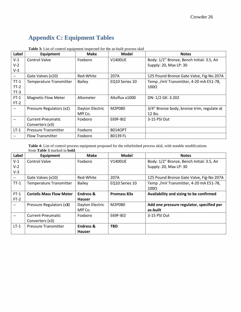
Appendix C: Equipment Tables Table 3: List of control equipment inspected for the as-built process skid
Label Equipment Make Model Notes
V-1 V-2 V-3
Control Valve Foxboro V1400UE Body: 1/2" Bronze, Bench Initial: 3.5, Air Supply: 20, Max LP: 30
-- Gate Valves (x10) Red-White 207A 125 Pound Bronze Gate Valve, Fig-No 207A
TT-1 TT-2 TT-3
Temperature Transmitter Bailey EQ10 Series 10 Temp ./mV Transmitter, 4-20 mA E51-78, 100Ω
FT-1 FT-2
Magnetic Flow Meter Altometer Altoflux x1000 DN: 1/2 GK: 3.202
-- Pressure Regulators (x2) Dayton Electric Mff Co.
M2P080 3/4" Bronze body, bronze trim, regulate at 12 lbs.
-- Current-Pneumatic Converters (x3)
Foxboro E69F-BI2 3-15 PSI Out
LT-1 Pressure Transmitter Foxboro B014OPT
-- Flow Transmitter Foxboro B0139 FL
Table 4: List of control process equipment proposed for the refurbished process skid, with notable modifications
from Table 3 marked in bold.
Label Equipment Make Model Notes
V-1 V-2 V-3
Control Valve Foxboro V1400UE Body: 1/2" Bronze, Bench Initial: 3.5, Air Supply: 20, Max LP: 30
-- Gate Valves (x10) Red-White 207A 125 Pound Bronze Gate Valve, Fig-No 207A
TT-1 Temperature Transmitter Bailey EQ10 Series 10 Temp ./mV Transmitter, 4-20 mA E51-78, 100Ω
FT-1 FT-2
Coriolis Mass Flow Meter Endress & Hauser
Promass 83x Availability and sizing to be confirmed
-- Pressure Regulators (x3) Dayton Electric Mff Co.
M2P080 Add one pressure regulator, specified per as-built
-- Current-Pneumatic Converters (x3)
Foxboro E69F-BI2 3-15 PSI Out
LT-1 Pressure Transmitter Endress & Hauser
TBD

Crowder 27
Appendix D: Process Tank Design
Figure 3: Design of proposed replacement process tank for the refurbished process skid.

Crowder 28
Appendix E: Control System Bill-Of-Material

Crowder 29
Appendix F: Miscellaneous Calculations
Process Tank Reference Sheet L3 for process tank layout and fitting placements
Specifications:
Inside Diameter: 12 inches
Outside Diameter: 12.5 inches (Thickness: 0.25 inches)
Capacity: 10 gallons
Cylindrical Height: 22 inches
Total Height: 26 inches, rounded top and bottom
Pressure Fitting: 1/2” fitting center-mounted 1.25” above bottom of cylindrical section
High-High-High Fitting: 1/2” fitting center-mounted 0.75” below top of cylindrical section
Total Volume in Tank
𝑉𝑇𝑜𝑡 = 𝑉𝐶𝑦𝑙 + 2𝑉𝐶𝑎𝑝
𝑉𝐶𝑦𝑙 = 𝜋𝑟2ℎ = 𝜋 ∗ 62 𝑖𝑛2 ∗ (22 𝑖𝑛) = 2488.14 𝑖𝑛3 = 10.77 𝑔𝑎𝑙
𝑉𝐶𝑎𝑝 =𝜋
3∗ ℎ𝑐𝑎𝑝(3𝑟𝑐𝑎𝑝
2 + ℎ𝑐𝑎𝑝2 ) =
𝜋
6∗ 1𝑖𝑛 ∗ (3 ∗ (36𝑖𝑛2) + 1𝑖𝑛2) = 0.508 𝑔𝑎𝑙
𝑉𝑇𝑜𝑡 = 10.73 𝑔𝑎𝑙 + 2 ∗ (0.507 𝑔𝑎𝑙) = 11.78 𝑔𝑎𝑙
Volume above High-High-High Drain
Fitting: 1” below cylindrical top
𝑉𝐴𝑏𝑜𝑣𝑒 = 𝑉𝐻𝐻𝐻 + 𝑉𝐶𝑎𝑝
𝑉𝐻𝐻𝐻 = 𝜋𝑟2ℎ𝐻𝐻𝐻 = 𝜋 ∗ 36𝑖𝑛2 ∗ 1𝑖𝑛 = 133.1𝑖𝑛3 = 0.498 𝑔𝑎𝑙 𝑉𝐴𝑏𝑜𝑣𝑒 = 0.498𝑔𝑎𝑙 + 0.508𝑔𝑎𝑙 = 1.00 𝑔𝑎𝑙
Volume below Pressure Fitting
Fitting: 1” above cylindrical bottom
𝑉𝐵𝑒𝑙𝑜𝑤 = 𝑉𝐿𝐿𝐿 + 𝑉𝐶𝑎𝑝
𝑉𝐿𝐿𝐿 = 𝜋𝑟2ℎ𝐻𝐻𝐻 = 𝜋 ∗ 36𝑖𝑛2 ∗ 1𝑖𝑛 = 133.1𝑖𝑛3 = 0.498 𝑔𝑎𝑙 𝑉𝐵𝑒𝑙𝑜𝑤 = 0.498𝑔𝑎𝑙 + 0.508𝑔𝑎𝑙 = 1.00 𝑔𝑎𝑙
Total Capacity
𝑉𝑂𝑣𝑒𝑟𝑎𝑙𝑙 = 𝑉𝑇𝑜𝑡 − 𝑉𝐻𝐻𝐻
𝑉𝑂𝑣𝑒𝑟𝑎𝑙𝑙 = 11.78𝑔𝑎𝑙 − 1.00 𝑔𝑎𝑙 = 10.78𝑔𝑎𝑙

Crowder 30
Appendix G: Process and Control System References
Common P&ID Symbols: https://www.edrawsoft.com/pid-legend.php
Constructing Wiring Diagrams: http://www.industrialcontrolsonline.com/training/online/how-
construct-wiring-diagrams
Reading Electrical Circuits: http://www.electricalengineeringschools.org/2014/a-beginners-
guide-to-circuit-diagrams/
ISA Electrical Symbols: http://avanceon.com/wp-content/uploads/2017/01/ISA_5.5.pdf
OSHA Electrical Safety: https://www.osha.gov/dte/grant_materials/fy07/sh-16615-07/train-the-
trainer_manual2.pdf

Crowder 31
Appendix H: Project Work Logs
Date Work Description Start Time
End Time Break Hours
Hours Total Hours
Location
5/23/2016 Mobilization of project. Purchase and gathering of lab materials. Review of project statement. Analysis of safety risks and requirements
6:30 PM 9:30 PM 0 3.00 3.00 Remote
5/24/2016 In-lab work. Tracing of existing process and process equipment. Gathering information, part numbers, etc.
6:30 PM 9:30 PM 0 3.00 6.00 On-site
5/26/2016 Initialization of AutoCAD environment. Documentation and summarization of work performed
6:30 PM 8:30 PM 0 2.00 8.00 Home
5/28/2016 P&ID design of current process. List of process equipment 8:00 AM 12:00 PM 0 4.00 12.00 Home
5/31/2016 P&ID design of current process 6:30 PM 9:30 PM 0 3.00 15.00 Home
6/2/2016 Meeting with Ed Evans 4:00 PM 4:30 PM 0 0.50 15.50 Whitby
6/7/2016 P&ID design of current process 6:30 PM 9:30 PM 0 3.00 18.50 Home
6/8/2016 P&ID design of current process 6:30 PM 9:30 PM 0 3.00 21.50 Home
6/21/2016 In-lab testing of analog output objects (I/P converters for the control valves)
5:00 PM 9:00 PM 0 4.00 25.50 On-site
6/22/2016 In-lab testing of analog output objects (I/P converters for the control valves). Offsite summarization of data. Research of process equipment for proposed system.
6:00 PM 10:00 PM 4.00 29.50 Whitby
6/23/2016 Summary sheet for 6/23 12:00 PM 1:00 PM 0 1.00 30.50 Remote
6/27/2016 In-lab comparison of P&ID to existing system. Revisions to AutoCAD as result. Evaluation of electrical safety
6:30 PM 9:30 PM 0 3.00 33.50 On-site
6/28/2016 Evaluation of pump, power supply, flow meters 6:00 PM 9:30 PM 0 3.50 37.00 On-site
6/29/2016 Purchase of tools, garden hose, adapter 4:00 PM 5:00 PM 0 1.00 38.00 Remote
6/29/2016 Testing of field input devices 5:00 PM 9:00 PM 0 4.00 42.00 On-site
6/29/2016 Summary sheet for 6/30 9:00 PM 9:30 PM 0 0.50 42.50 Home
6/30/2016 In-lab testing of select analog input devices 3:00 PM 4:00 PM 0 1.00 43.50 Home
6/30/2016 Meeting with Ed Evans 4:00 PM 4:30 PM 0 0.50 44.00 Home
7/3/2016 Revised P&ID Creation 9:00 AM 1:00 PM 0.5 3.50 47.50 Home
7/5/2016 Revised P&ID Creation 4:00 PM 8:00 PM 0 4.00 51.50 Office
7/6/2016 Draft Bill of Material for Control System 4:00 PM 6:00 PM 0 2.00 53.50 Office
7/7/2016 Evaluation of existing control system design 5:00 PM 9:00 PM 0 4.00 57.50 On-site
7/8/2016 Evaluation of existing control system design 5:00 PM 9:00 PM 0 4.00 61.50 On-site
7/9/2016 Research for potential tank replacement 1:00 PM 2:00 PM 0 1.00 62.50 Home
7/9/2016 Report Writing 2:00 PM 4:00 PM 0 2.00 64.50 Home
11/9/2016 Report Writing 1:00 PM 4:00 PM 0 3.00 67.50 Home
12/20/2016 Report Writing 4:00 PM 8:00 PM 0 4.00 71.50 Remote
12/21/2016 Report Writing 6:00 PM 10:00 PM 0 4.00 75.50 Home
12/22/2016 Report Writing 4:00 PM 8:00 PM 0 4.00 79.50 Home
1/4/2017 Report Writing 4:00 PM 8:00 PM 0 4.00 83.50 Home

Crowder 32
Date Work Description Start
Time End Time Break
Hours Hours Total
Hours Location
1/5/2017 Report Writing 4:00 PM 8:00 PM 0 4.00 87.50 Remote
1/6/2017 Report Writing 4:00 PM 8:00 PM 0 4.00 91.50 Home
1/23/2017 Report Writing 6:00 PM 10:00 PM 0 4.00 95.50 Remote
1/24/2017 Evaluation of process safety 6:00 PM 8:00 PM 0 2.00 97.50 Remote
1/25/2017 Evaluate existing control system design from documentation 6:00 PM 9:00 PM 0 3.00 100.50 Home
1/26/2017 AutoCAD Schematics for New Control System 6:00 PM 10:00 PM 0 4.00 104.50 Home
1/27/2017 AutoCAD I/O for New Control System 6:00 PM 10:00 PM 0 4.00 108.50 Home
1/30/2017 AutoCAD I/O for New Control System 6:00 PM 10:00 PM 0 4.00 112.50 Home
1/31/2017 AutoCAD I/O for New Control System 6:00 PM 10:00 PM 0 4.00 116.50 Home
2/1/2017 Changes to Proposed P&ID 6:00 PM 8:00 PM 0 2.00 118.50 Home
2/2/2017 Review of Progress with DCTech engineer 12:00 PM 2:00 PM 0 2.00 120.50 Office
2/3/2017 AutoCAD Panel Layout 6:00 PM 9:30 PM 0 3.50 124.00 Home
2/5/2017 Safety Analysis 12:30 PM 2:30 PM 0 2.00 126.00 Office
2/6/2017 Report Writing 1:30 PM 7:30 PM 0 6.00 132.00 Office
2/7/2017 Correspondance for Report Transmittal 1:30 PM 2:30 PM 0 1.00 133.00 Home
2/8/2017 AutoCAD Panel layout 6:00 PM 10:00 PM 0 4.00 137.00 Home
2/13/2017 AutoCAD Panel layout 6:00 PM 9:30 PM 0 3.50 140.50 Home
2/14/2017 AutoCAD Panel layout 6:00 PM 9:30 PM 0 3.50 144.00 Home
2/20/2017 AutoCAD 120 VAC wiring 6:00 PM 10:00 PM 0 4.00 148.00 Home
2/21/2017 AutoCAD 120 VAC wiring 6:00 PM 10:00 PM 0 4.00 152.00 Home
2/27/2017 Design review 12:00 PM 2:30 PM 0 2.50 154.50 Office
2/27/2017 Revisions to design based off meeeting 6:00 PM 9:30 PM 0 3.50 158.00 Home
2/28/2017 AutoCAD 24 VDC wiring 8:00 AM 2:30 PM 0.5 6.00 164.00 Office
2/28/2017 Design review 2:30 PM 3:00 PM 0 0.50 164.50 Office
2/28/2017 AutoCAD Terminal Strip diagrams 6:00 PM 9:30 PM 0 3.50 168.00 Home
3/1/2017 AutoCAD Terminal Strip diagrams 6:00 PM 9:30 PM 0 3.50 171.50 Home
3/3/2017 AutoCAD I/O Schematics 10:00 AM 4:00 PM 1 5.00 176.50 Home
3/6/2017 AutoCAD I/O Schematics 8:00 AM 2:30 PM 1 5.50 182.00 Office
3/4/2017 Design review 8:00 AM 9:00 AM 0 1.00 183.00 Home
3/6/2017 Revisions to design 8:00 AM 12:00 PM 0 4.00 187.00 Office
3/8/2017 Meeting with Ed Evans 2:30 PM 3:00 PM 0 0.50 187.50 Remote
3/28/2017 Revisions to design 1:00 PM 7:00 PM 0 6.00 193.50 Home
3/29/2017 Revisions to report 1:00 PM 8:00 PM 0 7.00 200.50 Home
3/30/2017 Revisions to report 1:00 PM 5:00 PM 0 4.00 204.50 Home
4/6/2017 Revisions to report 8:00 AM 11:00 AM 0 3.00 207.50 Office
4/11/2017 Finalization of materials 2:00 PM 5:00 PM 1 2.00 209.50 Office